Page 1
Huang, Kuo and Li, Bo and Yan, Yuying and Li, Yong and Twaha, Ssennoga and Zhu, Jie (2017) A comprehensive study on a novel concentric cylindrical thermoelectric power generation system. Applied Thermal Engineering, 117 . pp. 501-510. ISSN 1873-5606
Access from the University of Nottingham repository: http://eprints.nottingham.ac.uk/40903/1/ISHT9-revised%20final.pdf
Copyright and reuse:
The Nottingham ePrints service makes this work by researchers of the University of Nottingham available open access under the following conditions.
This article is made available under the Creative Commons Attribution Non-commercial No Derivatives licence and may be reused according to the conditions of the licence. For more details see: http://creativecommons.org/licenses/by-nc-nd/2.5/
A note on versions:
The version presented here may differ from the published version or from the version of record. If you wish to cite this item you are advised to consult the publisher’s version. Please see the repository url above for details on accessing the published version and note that access may require a subscription.
For more information, please contact [email protected]
Page 2
A Comprehensive Study on a Novel Concentric Cylindrical Thermoelectric
Power Generation System Kuo Huang1, Bo Li1, Yuying Yan1,2**, Yong Li3, Ssennoga Twaha1, Jie Zhu1
1 Fluids & Thermal Engineering Research Group, Faculty of Engineering, University of Nottingham, UK 2 Fluids & Thermal Engineering Research Centre, University of Nottingham Ningbo, China
3School of Automotive and Mechanical Engineering, South China University of Technology, China
Abstract: This paper presents the novel designs of a concentric cylindrical thermoelectric
generator (CCTEG) and an annular thermoelectric module (ATEM). The simulations are
carried out to compare the performance of ATEM and the conventional square-shaped
thermoelectric module (STEM). The heat pipe technology is introduced into the heat sink
system in order to enhance the heat transfer in the radial direction of exhaust gas flow. A new
index termed as the heat transfer filling factor 𝑓 has been introduced which quantities the level
of space utilisation for thermoelectric modules (TEMs). The correlation between the coolant
flow rate and TEM performance is also carried out. Experimental work is also carried out to
demonstrate the viability of using the heat pipes for heat transfer enhancement as well proving
the viability of the design. The simulations indicate that the open circuit electric potential of
the ATEM is 17% more than that of the STEM. The experimental results show that the CCTEG
system performs well under various conditions. This results also demonstrate that the concept
of adding heat pipes to the heat sink system is a practical solution to achieve higher
thermoelectric generator (TEG) performance while maintaining the compactness of the TEG
system. A heat transfer filling factor of 0.655 is achieved for the CCTEG system which is
higher compared to the existing TEG systems. Moreover, a higher coolant flow rate contributes
to obtaining a better performance of the TEG system. It is important to note that the introduced
index can give guidance for further optimisation design of TEG systems.
Keywords: Thermoelectric power generation, Heat enhancement, Exhaust heat, Temperature-
dependent material properties, Heat pipes, Heat exchanger
1 Introduction
Previous decades have seen enormous developments in the renewable technologies by
utilizing the alternative ways to obtain the usable energy. Thermoelectric heat recovery, as one
of the most promising clean technologies, has attracted a greater attention due to its unique
merits of energy conversion [1]. Unlike the traditional fossil fuel energy systems, TEG system
converts waste heat directly into electricity through the Seebeck effect of the semiconductor
materials whereby a temperature difference is maintained between the hot and cold side of the
TEG module. TEG systems have the advantages of silent operation, high reliability, and they
have no moving or mechanically complex components rendering them lasting for a very long
time. They also operate at wider operational temperature range than most existing energy
Corresponding author.
E-mail address: [email protected]
Page 3
recovery systems [2, 3]. However, the major challenge of the TEG system is the relatively low
heat to electricity conversion efficiency[4]. Therefore, many research groups have made
significant efforts on the improvement of the figure of merit for thermoelectric materials, such
as BiTe, ZnBe, SiGe, TiO and even new nanocrystal or nanowire thermoelectric materials.
Therefore, due to such booming research, TEG systems will be possibly applied in automotive
waste heat industry in the near future [5-7].
In addition to material research developments, thermal scientists and system engineers focus
mainly on the optimisation of geometric parameter of TEMs and heat exchanger. Liu et al. have
performed CFD simulation and experimental study on the structural design of the heat
exchanger to improve the efficiency of TEG system [8]. Furthermore, the performance of the
TEG system under real working conditions is examined and a maximum power output of 944
W is obtained [9]. Lee has studied the optimal design of thermoelectric devices with
dimensional analysis [10]. The optimum designs including the power output and the efficiency
on the external load resistance as well as the geometry of thermoelectric units. Liu et al. and
Liang et al. have investigated the performance of two-stage thermoelectric generator systems
[11, 12]. The results show that the power output and conversion efficiency of the two-stage
TEG increase significantly by changing the heat transfer coefficient of the two stages and are
noted to be higher than those of the single-stage TEG.
The influence of the engine working condition and the boundary condition on TEG system
performance in the vehicle are also being researched. Yu et al. found out that multiple vehicular
driving conditions might lead to the significant variation of TEG performance [13]. The results
indicate that the engine speed is a major factor affecting the TEG performance. The results
deduce that the higher the vehicle speed, the better the TEG performance. A higher road grade
is also spotted to increase the power output of TEG significantly. He et al. have studied the
influence of different cooling methods on the performance of TEG system [14]. The results
reveals that the power output is higher with liquid cooling than air cooling whereas the counter-
flow arrangement leads to higher power output though a much larger area is needed compared
to the parallel-flow method. Other factor which needs consideration are the space and weight
of the vehicle. It is noted that, in practice, there is limited space in the vehicle exhaust system;
so the light weight and the size of the TEG are also vital factors in applying the TEG for fuel
economy [15]. Wang et al. presented a TEG design with heat pipes-assisted heat exchanger
structure to overcome the common conflicts between the needs for high heat flux into TEG and
the limitation of overall heat exchanger dimensions and weights. Therefore, the need of light
weighted thermoelectric generator system is very necessary for the development of vehicular
TEG systems. The existing TEG systems are often too bulky to be applied in the exhaust system.
In this paper, a novel design of concentric cylindrical thermoelectric generator (CCTEG)
system is presented for use in the exhaust system in the passenger car. The new design is
capable of adapting to the shape of the exhaust pipe besides accommodating more TEMs unlike
other TEG system designs of the same installation length. Given the form of the CCTEG
system, a new annular thermoelectric module (ATEM), which is different from the previous
square thermoelectric module (STEM), is also designed for the use of CCTEG system.
Therefore, a relatively compact heat exchanger is necessary for the TEG system. In addition,
Page 4
heat pipes are applied to enhance the radial heat transfer of the whole system by means of
conducting the heat directly into the annular TEM modules [16, 17]. Mathematical analysis for
the design are presented and experiments are carried out to verify the feasibility of CCTEG.
Simulations have been done to investigate the difference in performance between the annular
TEM and square TEM. Moreover, different performance indicators of evaluation are used to
compare these two different shapes of TEMs and analyse the geometric influence on the TEM.
Additionally, a model-scale experimental prototype and test rig for CCTEG are also
constructed to examine the feasibility of using of heat pipes in this TEG system.
2 The Design of Concentric Cylindrical Thermoelectric Generator
The described concentric cylindrical TEG design is as shown in Fig. 1. The main components
of this TEG are the hot plates, cooling plates, heat pipes, concentric thermoelectric modules,
and water jacket. The arrows indicated that the waste heat of the exhaust gas is conducted by
heat pipes towards the hot side of the thermoelectric generator. On the cold side of TEM, the
cooling plate also discharges heat to the water jacket via heat pipes. The purpose of using heat
pipes is to divert the waste heat in the radial direction from engine exhaust pipe and discharge
the heat to the water jacket. In addition, the heat transfer in the radial direction is enhanced due
to the characteristic of super heat conductivity of the heat pipes.
The competitive advantage of CCTEG is the less installation space and weight required than
conventional bulky TEG system. Since the installation space in vehicle exhaust system is
limited in most scenarios, a relatively compact heat exchanger is imperative for the
implementation of TEG systems. Moreover, the weight of the overall auxiliary devices is also
a key factor for the fuel consumption of vehicles. The application of heat pipes makes it
possible to reduce the weight of heat exchanger, rendering the CCTEG lighter than any other
TEG systems.
Fig. 1. Schematic of the concentric cylindrical thermoelectric generator
Page 5
a b
Fig. 2. 3D schematic of the concentric cylindrical thermoelectric generator
(a) Exhaust gas flow through inner pipe (b) Exhaust gas flow through outer pipe
As depicted in Fig. 2, the two sections represent the minimum repeat units of the overall
system which can be segregated by the need of power rating. The minimum repeat unit is
comprised of 4 ATEMs, 3 hot plates and 2 cooling plates including 12 heat pipes in each plate
marked in blue and red colour in the Fig. 2 (a) and 2(b) respectively. The exhaust gas flows
throw the inner pipe of the system in Fig. 2 (a) while the coolant flows in a constrained space
shaped by the heat pipes, the surface of the cooling plate and the shell of the heat exchanger.
Considering the various applications and the performance needs, this configuration can be
interchanged by switching the channels of the gas and the coolant flows. As described in Fig 2
(b), the coolant flow can be arranged in an axial flow by replacing the gas flow in Fig.2 (a)
baring mind the heat convection in the coolant. The gas flow, therefore, can be allocated at the
outer side where the extra heat sinks on the heat pipes can be installed. In this way, a higher
power generation performance can be achieved due to the heat transfer enhancement between
the heat pipes and gas flow.
3 The Modelling of Concentric Cylindrical Thermoelectric Generator
The three-dimensional models of STEM and ATEM are analysed in CAD software. Both
thermal analysis and thermoelectric performance of these two models are simulated in the CFD
software.
3.1 Material properties of TEM for simulation and experiment
The previous studies of the thermoelectric generator mainly focused on the heat exchanger
and the improvement of thermoelectric materials, but the influence of the topological shape of
thermoelectric modules has not attracted much attention by the researchers. A different design
Page 6
for the thermoelectric module – ATEM is described in this paper. The aim of this module is to
fit the novel design of CCTEG system.
The two different shapes of thermoelectric modules that are described in this study are shown
in the Fig. 3. Both modules share the same number of thermoelectric units and the same
material properties. The geometric details of the TEMs are listed in Table 1.
Table 1 Geometric details of TEMs
Parameters Thermoelectric Leg Copper Ceramic Plate
Square TEM Annular TEM
Length (mm) 2.55 5.8 65.7 -
Width (mm) 2.55 2.55 65.7 -
Height (mm) 2.55 0.3 0.7 0.7
Inner Diameter (mm) - - - 50.8
External Diameter (mm) - - - 101.6
Each TEM in this study contains 210 units. These units are electrically connected in series
implying that the electrical currents through them are the same. On the other hand, the heat
passes through these units simultaneously, meaning that they are thermally connected in
parallel. A single TEM unit includes a P-type and an N-type leg, connected together with
copper strips. The electrical insulation of the TEM units is achieved by placing AlN ceramic
plate on the top and bottom sides of modules.
(a) (b)
Fig. 3. Structure of (a) square TEM and (b) annular TEM
During the simulation, the temperature-dependent Seebeck coefficient, thermal conductivity,
and the electrical resistivity for both N-type and P-type thermoelectric legs are given by the
polynomials whose coefficients are summarized in Table 2 [18-20]. The coefficients of
polynomials represent the material properties from which the TEG modules are made.
Page 7
Table 2 Material parameters of a single TEM unit
Parameters Semiconductors Copper ALN
Ceramic
Seebeck
coefficient
(V/K)
α0(100) α 1(10-7) α 2(10-9) α 3 (10-
12)
α 4 (10-
16)
- - P-type 0.0002 7 -3 4 -5
N-type -0.0002 -3 1 -1 1
Thermal
conductivity
(W/m∙K)
κ0(100) κ 1(10-5) κ 2(10-7) κ 3 (10-
10) κ 4 (10-12)
350 285 P-type 0.016 -4 2 -6 3
N-type 0.0122 -3 6 3 -8
Electrical
conductivity
(S/m)
ρ0(100) ρ 1(10-6) ρ 2(10-9)
5.90 - P-type 0.0007 7 -1
N-type 0.0009 6 -9
3.2 Simulation boundary conditions
The thermoelectric material used in the simulation is bismuth telluride (Bi2Te3). The
numerical simulation is performed at a steady state for both of the two modules. The governing
equations for the electric and conjugate heat transfer are modified according to the conditions
set out to perform the analysis of the designs.
The heat flux and heat flow equations are
𝑞 = 𝛼𝑇𝐽 − 𝜅𝛻𝑇 (5)
�̇� = 𝑞 ∙ 𝐴 (6)
Thermoelectric effects are caused by coupling between charge transport and heat transfer.
Under isotropic conditions, the linear relations are presented as
𝐸 = 𝐽𝜌 + 𝛼𝛻𝑇 (7)
𝐽 = 𝜎 (𝐸 − 𝛼𝛻𝑇) (8)
where σ = 1/ρ is the electric conductivity; E is the electric field; ∇T is the temperature gradient.
The electric field of the thermoelectric material is affected by the current density and the
temperature gradient. The coefficients are known according to the Ohm’s law and the Seebeck
effect. These two equations are based on Onsager-Callen theory on irreversible
thermodynamics [21].
As for the steady-state conditions, the governing equations for constant current and heat
transfer of inhomogeneous thermoelectric material can be described by
𝛻 ∙ 𝐽 = 0 (9)
𝛻 ∙ (𝜅𝛻𝑇) + 𝐽2𝜌 − 𝑇𝐽[(𝑑𝛼
𝑑𝑇) ∙ 𝛻𝑇 + 𝛻𝛼|𝑇] = 0 (10)
where 𝛻𝛼|𝑇 is the gradient at a given temperature.
Considering one of the thermoelectric units to represent the whole CCTEG module, assuming
a uniform material and dimensions for each of the units, Eq. (8) for one-dimensional analysis
at steady state gives the non-linear differential governing equation as;
Page 8
𝑑2𝑇
𝑑𝑥2 − 𝐼
𝑑𝛼
𝑑𝑇
𝐴𝜅𝑇
𝑑𝑇
𝑑𝑥+
𝐼2𝜌
𝐴2𝜅= 0, (𝑇(0) = 𝑇𝑐 , 𝑇(𝐿) = 𝑇ℎ) (11)
where A is the cross-sectional area of the thermoelectric units [22].
In practice, the TEG system absorbs the heat from the engine exhaust gas and uses a coolant
to obtain a higher temperature gradient between the cold and hot side. Therefore, the heat
transfer coefficient is the key factor which influences the heat transfer in the TEM. The heat
transfer coefficient for the forced air convection and forced water convection, in the present
study, are set at 40 W/m2∙K and 6000 W/m2∙K respectively.
The capacity of the TEG system is highly related to the mass flow rate and the temperature
of exhaust gas, which is closely associated with the engine speed and the vehicle load. The
boundary conditions used in the simulation are shown in Fig. 4 [15]. During the simulation, the
hot side boundary condition of a single TEM is the inward heat flux or hot side temperature
which is calculated by the exhaust gas temperature and mass flow rate. This is intended to
ensure that the temperature maintained at the same value under the same engine speed.
Moreover, the heat transfer coefficients on the hot and cold side of both TEM remain
unchanged.
3.3 Description of the experimental setup
A scaled-up experimental prototype of CCETG was configured and measurements of its
overall performance were carried out under various boundary conditions. The schematic of the
test rig is shown in Fig. 5 and Fig. 6. The TEG block was composed of 16 thermoelectric
modules in four layers, with cooling plates and hot plates. The TEMs were made of a
semiconductor material Bi2Te3 and had dimensions of 40 mm x 40 mm x 3.8 mm composed of
210 thermoelectric units. Thermal interface materials were placed at the interface of solid
surfaces to enhance the heat transfer.
Fig. 4. Boundary conditions for the performance simulation
Page 9
Two controllable cartridge heaters rated at 100 W were used to supply heat on the hot side.
The heat supply to the TEG system could be adjusted by changing the voltage input. This
system was cooled by water through the water jacket. The temperature at the heat source and
heat sink was measured by K-type thermocouples and the flow rate of cooling water was
measured by a flowmeter. The thermocouples were located in slots drilled on the surface of the
hot plate. The temperature, flow rate and voltage were recorded by a DT500 series III Data
taker. A rheostat resistance ranging from 0 Ω to 40 Ω was connected to the TEG system to
provide the adjustable external load.
However, the result of the experimental test shows some discrepancy with the expected
results, which is caused by the instrumental errors. The difference between the expected and
actual maximum power obtained is dependent on the errors in both voltage and current
measurements. The error in the heat flux temperature set-point was based on the thermocouple
accuracy and the errors in the temperature controller. The errors in the temperature controller
were a combination of the indication error of the thermocouple temperature and the overshoot
deviation from the set-point temperature.
Fig. 5. Schematic of the test rig
Fig. 6. Image of the constructed test-rig utilised throughout the experiment
Rheostat
TEG Block Valve
Flow rate Meter
Ammeter
Voltmeter
Page 10
4 Results and Discussion
4.1 Performance comparisons of single TEM
Assuming that the inward heat flux of each TEM remains constant, the total inward heat flow
is proportional to the heat transfer area according to Eq. (5) and (6). Based on the geometric
comparisons in Table 1, the main difference between these two TEMs is the heat transfer area.
The available heat transfer areas for the STEM and ATEM are found to be 4316.49 mm2 and
6077.41 mm2 respectively through calculations.
According to energy conservation, the power output generated by a single thermoelectric unit
is expressed as:
𝑃𝑜𝑢𝑡 = 𝑄ℎ − 𝑄𝑐 = 𝛼𝐼(𝑇ℎ − 𝑇𝑐) − 𝐼2𝑅 (13)
The power generated at the load is expressed as:
𝑊 = 𝐼2𝑅𝐿 (14)
where RL is the load resistance.
Given the open circuit electric potential V=α∙∇T, the current in circuit is expressed as [23]:
𝐼 =𝛼(𝑇1−𝑇2)
(𝑅𝐿+𝑅) (15)
The maximum power efficiency is the specific conversion efficiency where the power
reaches the maximum. From Eq. (14) and (15), the maximum power can be computed as:
�̇� = (𝛼∆𝑇
𝑅𝐿
𝑅+1
)
2
𝑅𝐿
𝑅 (16)
The maximum power is obtained at RL=R and by inserting this relation into Eq. (16), this
gives:
�̇�𝑚𝑎𝑥 =𝛼2∆𝑇2
4𝑅 (17)
The conversion efficiency of the TEG is in the form of [24]
𝜂𝑡 = 𝑊
𝑄ℎ (18)
Fig. 7 (a) and (b) show the different performances of each TEM, under the same inward heat
flux at 5 W/cm2. From the results, the heat transfer area has a considerable level of influence
on the temperature distribution on the hot side of the TEM. Since the heat exchange area of
ATEM is larger than that of STEM, ATEM can conduct more heat with the same inward heat
flux. In this case a higher temperature gradient between the hot and cold side of TEM for the
ATEM resulting into a higher open circuit electric potential. Fig. 7 (a) and (b) indicate that the
average hot side temperature of ATEM is 602 K which is higher than the average hot side
temperature of the STEM which is 500 K. The temperature gradient between both sides of
ATEM and STEM is 213 K and 150 K respectively. As a result, the ATEM generates a 14.5 V
of open circuit electric potential which is 2.1 V higher than that of STEM under the same heat
flux condition.
Page 11
(a) (b)
(c) (d)
Fig. 7. Performance comparison for ATEM (a & c) and STEM (b & d)
1. (a & b) under inward heat flux q = 50000 W/m2 (Neumann boundary condition), heat transfer coefficient hc= 6000 W/m2 K,
Tcoolant= 288 K (Cauchy boundary condition on the cold side)
2. (c & d) at hot side temperature Th = 643 K (Dirichlet boundary condition), heat transfer coefficient hc= 6000 W/m2 K, Tcoolant=
288 K (Cauchy boundary condition on the cold side)
Fig. 7 (c) and (d) show the simulation result of both TEMs operating at the same hot side
temperature of 643 K. The figures indicate that the ATEM module performs better than STEM
at the same hot side temperature. As long as the hot side temperature is kept the same for the
two TEMs, a lower average cold side temperature for ATEM is achieved due to the larger heat
transfer area enabling it to acquire a higher heat dissipation rate. Consequently, the respective
average cold side temperatures for ATEM and STEM are 352 K and 417 K, representing a
difference of 65 K in the two TEMs. This difference obviously affects the open circuit electric
potential generated by TEM because the Seebeck effect responsible for generating this
potential is actuated by the temperature difference on the two sides of the TEM. Therefore, the
open circuit electric potential for ATEM is higher at 19.6 V than the one for STEM at18.9 V.
As mentioned above, two kinds of boundary conditions are adopted. The first one is
Neumann boundary condition on the hot side and Cauchy boundary condition on the cold side.
The second one is Dirichlet boundary condition on the hot side and Cauchy boundary condition
on the cold side. The reason for specifying these two different sets of boundary conditions is
that the various measurements hot side temperature in practical and simulation are taken. In
some situation, the exact value of hot side temperature is difficult to be obtained, so the
temperature is often calculated by the heat flux on the hot side which is the Neumann boundary
Page 12
condition. During simulation, the hot side temperature is often specified for a more accurate
simulation. As a result, Dirichlet boundary condition is also applied in the second part of the
simulation.
4.2 Influence of heat transfer area
Under the same inward heat flux, the primary difference of these two TEMs is the heat
transfer area which leads to hotter surface temperature distribution at ATEM than at STEM hot
side surfaces. As a result, the different temperature distributions of the two TEMs influence
their power generation capabilities represented by their open circuit electric potential values.
In this part of the study, the influence of engine speed is taken into consideration, as the
variation of engine speed affects the total inward heat flux of TEM. In this way, the influence
of automotive driving cycle to the performance of TEM is investigated.
Fig. 8 shows the average temperature of both TEMs on the hot side under different inward
heat flux which is calculated at various engine speeds. The curves indicate that the hot side
average temperature of ATEM is higher than that of STEM due to the 28.9% larger heat transfer
area of ATEM. Furthermore, the hot side average temperature is in direct proportion to inward
heat flux. Under the same inward heat flux, the hot side average temperature of ATEM is 20
~ 25 K higher than that of STEM. This difference results in a considerable variation in the
temperature gradient so that the open circuit electric potential of ATEM is again greater than
that of STEM.
Fig. 8. Hot side average temperature of both TEM under different inward heat flux
Fig. 9 shows the open circuit electric potential of the two TEMs under different engine
working conditions. Since the temperature gradient of ATEM is higher than that of STEM, the
open circuit electric potential generated by ATEM is also higher in general. Under various
inward heat fluxes caused by different engine speed, the open circuit voltage generated by
ATEM is 2.5 V ~ 2 V higher than STEM. This difference becomes larger when the inward heat
flux is lower because the two curves show a parabolic shape. This is due to the characteristic
of semiconductor material which is considered as temperature-dependent in this case, which is
different from previous investigations with constant material parameters [25].
Page 13
The study also demonstrates that each TEM has an optimal performance point which is a
function of inward heat flux as observed in Fig. 9. Therefore, the automotive driving condition
should be taken into account when the TEG system is being designed for a specific vehicle
exhaust system. In order to obtain a better output voltage and power, the position of TEG
system in the entire exhaust system also needs to be considered carefully.
4.3 Experimental results
In addition to the simulation studies, proof-of- concept test is also carried out in a model-scale
test rig and results are compared with those of the simulations. In addition, to verify the
accuracy of these results, Hi-Z performance calculator is utilised during the comparative
analysis of the experimental and simulation results.
Fig.10 shows the comparison of the variation in power output versus varying load resistance
(RL) under different hot side temperature. As shown in Fig. 10, three load curves exhibit the
same trends though they have a marginal difference under different load resistance conditions.
The curves of simulation and Hi-Z calculator in Fig. 10 (a), 10 (b) and 10 (c) have a similar at
a lower load resistance but slightly deviate from each other at a higher load resistance. These
differences could be caused by the difference in accuracies and errors during calculations of
the internal electric resistance and the heat flux. In Hi-Z performance calculator, there is an egg
crate area which has a lower heat transfer coefficient than other areas. Besides, the internal
electric resistance in the simulation is calculated by continuous integration method which is
different from Hi-Z performance calculator. In addition, the application of different input
heating power may also cause the difference between these curves.
Fig. 9. Open circuit electric potential of both TEM under different inward heat flux
Page 14
(a)
(b)
(c)
Fig. 10. Comparison of model performance predicted by the simulation, Hi-Z calculator, and experiment
result
(a) under 353 K of the hot side temperature; (b) under 393 K of the hot side temperature;
Page 15
(c) under 423 K of the hot side temperature;
The trend of these three power output curves is practically the same although different hot
side temperature is applied. The peak point of each curve occurs when the inner resistance of
the TEM matches the external load resistance. The power output increases sharply at lower
load resistance and declines slowly at a higher load resistance which seem to be relatively
levelling off afterwards. In Hi-Z Model, the increment and reduction of the power output are
more noticeable due to the differences in the calculation method. The agreement between the
simulation results and the experimental data is better than that of Hi-Z Model.
Fig.10 (a) is the comparison of the simulation, Hi-Z calculator and experiment results at 353
K for the hot side temperature, using the same thermal conductivity obtained in the previous
part. The hot side temperature is as a result of different inward heat flux which is used in
simulation and varies from 353 K to 384 K representing an increment of 31 K. The comparisons
of the different hot side temperatures are shown in Fig. 10 (b) and (c). These results show good
agreement with the result at 353 K hot side temperature in Fig.10 (a). When the hot side
temperature and temperature difference become larger, the results predicted by the Hi-Z and
simulation deviate from each other where the deviation increases with the increment of hot side
temperature and temperature difference. Such discrepancies could be caused by using the
different temperature-dependent material properties and the difference of the temperature
variation within the thermoelectric unit.
Fig. 10 also shows the variation for power output with the load resistance in the experimental
test under different conditions of hot side temperature. In these three figures, the experimental
curve is in good agreement with the other two curves. However, actual results of the experiment
have a minor difference with simulation and Hi-Z calculator, particularly at the higher hot side
temperature. There are two main reasons which lead to such a discrepancy. Firstly, instrument
errors and reading errors are inevitable in the test. Moreover, due to the thermal loss in the test,
the actual heat transfer to the test prototype is not as much as the cartridge heaters supplied.
When the temperature increase, the temperature difference between test rig and ambient
becomes larger, thus the heat loss was exacerbated. In the Fig. 10 (c), the experiment data
shows the obvious difference with the other two curves.
4.4 Heat transfer filling factor
In practice, the installation space for TEG system is highly restricted, which means delicate
considerations of location and configuration should be taken into account. Especially, there is
little room for such an auxiliary system in the existing passenger car platform. On the other
hand, the whole TEG system needs to take in more heat from the exhaust gas in the same area
or length for higher recuperation performance. As the various designs of heat recovery system,
the area of the heat exchanger in each TEG system are significantly different. In this present
study, different topological design TEG systems from Purdue University is introduced here as
a comparison [26, 27]. Provided that TEG systems can be easily scalable, we consider only the
ratio of TEM and heat exchanger areas, rather than their absolute values. In this study, a new
measurable indicator is described. The ratio of TEM to heat exchanger areas is named as the
Page 16
heat transfer filling factor: 𝑓 = 𝐴𝑇𝐸𝑀 𝐴𝐸𝑥𝑐ℎ𝑎𝑛𝑔𝑒𝑟⁄ . The heat transfer filling factor of different
topological designed TEG systems and the CCTEG system are shown in Table 3.
Table 3 Heat transfer filling factor of different topological TEG
Topological Shape Longitudinal Transverse Hexagonal Cylindrical Concentric
Cylindrical
Filling Factor 0.458 0.43 0.521 0.575 0.655
The heat transfer filling factor is a measurable indicator of the level of space utilisation in
installed place. As seen in Table 3, the CCTEG system has the highest heat transfer filling
factor which means, in the same space, more ATEM in the CCTEG system can be installed.
Practically, the problem of narrow installation space can be solved for TEG system in existing
vehicles without deep modifications. This factor can give guidance for further optimal design
of TEG systems.
In most situations, the increment of back pressure in the whole exhaust system has an adverse
effect on the fuel economy of the vehicle. By introducing the heat pipes, the CCTEG system
has a higher heat transfer filling factor which means it can transport more heat in the same area.
This will also help to reduce the complexity of the exhaust system and result in the decrease of
back pressure increment. Furthermore, due to the high heat transfer filling factor, the same
amount of coolant can obtain a better cooling effect. This benefit results in reducing the amount
of power supply to the water pump, subsequently improving the fuel economy. Another
advantage of applying heat pipes is that they may contribute to the obsolete of mufflers as the
noise and vibrations in the exhaust can be absorbed in the heat pipe as protruded pin fins. This
will be investigated as the integration of heat recovery and noise reduction technologies in the
future.
4.5 Influence of coolant parameter
In addition to the effects of hot-side boundary condition and heat exchanger, the coolant flow
rate also affects the maximum power output of the TEG system. Varying the coolant flow rate,
the external resistances (RL) also change which leads to the different maximum power output
of the whole system. At lower coolant flow rates, the overall internal temperature of the
prototype is higher than that at higher flow rates because the temperature of the cold surfaces
is greater at low flow rates. Therefore, given the fact that internal resistance increases with
temperature, the matched load resistance for maximum power will increase.
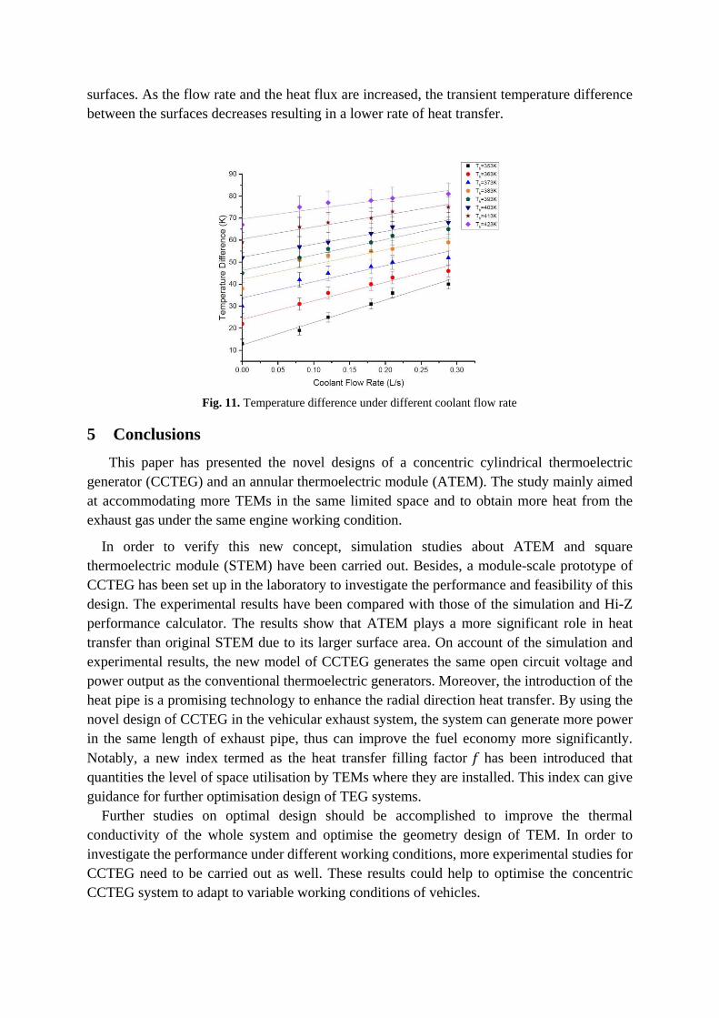
In Fig. 11, the specific temperature differences of TEG modules at each specific coolant flow
rate are illustrated with various hot side temperature conditions. From the figure, the
temperature difference increases as the cooling flow rate increases can be observed.
Additionally, the slopes of each plot that the highest rate of temperature difference increase
occurred at the lower flow rates. As the flow rate increases, the slope ratio of temperature
difference decreases accordingly. Moreover, the overall rate of temperature difference increase
is larger at lower hot-side temperatures than that observed at higher temperatures. This increase
can be attributed to the larger initial temperature difference applied between the hot and cold
Page 17
surfaces. As the flow rate and the heat flux are increased, the transient temperature difference
between the surfaces decreases resulting in a lower rate of heat transfer.
Fig. 11. Temperature difference under different coolant flow rate
5 Conclusions
This paper has presented the novel designs of a concentric cylindrical thermoelectric
generator (CCTEG) and an annular thermoelectric module (ATEM). The study mainly aimed
at accommodating more TEMs in the same limited space and to obtain more heat from the
exhaust gas under the same engine working condition.
In order to verify this new concept, simulation studies about ATEM and square
thermoelectric module (STEM) have been carried out. Besides, a module-scale prototype of
CCTEG has been set up in the laboratory to investigate the performance and feasibility of this
design. The experimental results have been compared with those of the simulation and Hi-Z
performance calculator. The results show that ATEM plays a more significant role in heat
transfer than original STEM due to its larger surface area. On account of the simulation and
experimental results, the new model of CCTEG generates the same open circuit voltage and
power output as the conventional thermoelectric generators. Moreover, the introduction of the
heat pipe is a promising technology to enhance the radial direction heat transfer. By using the
novel design of CCTEG in the vehicular exhaust system, the system can generate more power
in the same length of exhaust pipe, thus can improve the fuel economy more significantly.
Notably, a new index termed as the heat transfer filling factor 𝑓 has been introduced that
quantities the level of space utilisation by TEMs where they are installed. This index can give
guidance for further optimisation design of TEG systems.
Further studies on optimal design should be accomplished to improve the thermal
conductivity of the whole system and optimise the geometry design of TEM. In order to
investigate the performance under different working conditions, more experimental studies for
CCTEG need to be carried out as well. These results could help to optimise the concentric
CCTEG system to adapt to variable working conditions of vehicles.
Page 18
Acknowledgements
The work was supported by FAW R&D Centre China and also partially by Ningbo Science
and Technology Bureau’s Technology Innovation Team Project under Grant No. 2016B10010.
The authors would further acknowledge the support from China Scholarship Council (CSC)
for the first author’s scholarship.
References
[1] Ssennoga Twaha, Jie Zhu, Yuying Yan, Bo Li, A comprehensive review of thermoelectric technology:
Materials, applicatio6ns, modelling and performance improvement, Renewable and Sustainable Energy Reviews,
65 (2016) 698–726.
[2] M. Karvonen, R. Kapoor, A. Uusitalo, V. Ojanen, Technology competition in the internal combustion engine
waste heat recovery: a patent landscape analysis, Journal of Cleaner Production, 112 (2016) 3735-3743.
[3] D.V. Singh, E. Pedersen, A review of waste heat recovery technologies for maritime applications, Energy
Conversion and Management, 111 (2016) 315-328.
[4] B.D. In, K.H. Lee, A study of a thermoelectric generator applied to a diesel engine, Proceedings of the
Institution of Mechanical Engineers Part D-Journal of Automobile Engineering, 230 (2016) 133-143.
[5] D.K. Aswal, R. Basu, A. Singh, Key issues in development of thermoelectric power generators: High figure-
of-merit materials and their highly conducting interfaces with metallic interconnects, Energy Conversion and
Management, 114 (2016) 50-67.
[6] T.J. Hendricks, S. Yee, S. Leblanc, Cost Scaling of a Real-World Exhaust Waste Heat Recovery
Thermoelectric Generator: A Deeper Dive, Journal of Electronic Materials, 45 (2016) 1751-1761.
[7] H.P. Martin, A. Ponicke, M. Kluge, I. Sichert, A. Rost, S. Conze, K. Watzig, J. Schilm, A. Michaelis, TiOx-
Based Thermoelectric Modules: Manufacturing, Properties, and Operational Behavior, Journal of Electronic
Materials, 45 (2016) 1570-1575.
[8] X. Liu, Y.D. Deng, K. Zhang, M. Xu, Y. Xu, C.Q. Su, Experiments and simulations on heat exchangers in
thermoelectric generator for automotive application, Applied Thermal Engineering, 71 (2014) 364-370.
[9] C. Tao, G. Chen, Y. Mu, L.S. Liu, P.C. Zhai, Simulation and Design of Vehicle Exhaust Power Generation
Systems: The Interaction Between the Heat Exchanger and the Thermoelectric Modules, Journal of Electronic
Materials, 44 (2015) 1822-1833.
[10] H. Lee, Optimal design of thermoelectric devices with dimensional analysis, Applied Energy, 106 (2013) 79-
88.
[11] C.X. Liu, X.X. Pan, X.F. Zheng, Y.Y. Yan, W.Z. Li, An experimental study of a novel prototype for two-
stage thermoelectric generator from vehicle exhaust, Journal of the Energy Institute, 89 (2016) 271-281.
[12] X.Y. Liang, X.X. Sun, H. Tian, G.Q. Shu, Y.S. Wang, X. Wang, Comparison and parameter optimization of
a two-stage thermoelectric generator using high temperature exhaust of internal combustion engine, Applied
Energy, 130 (2014) 190-199.
[13] S.H. Yu, Q. Du, H. Diao, G.Q. Shu, K. Jiao, Effect of vehicle driving conditions on the performance of
thermoelectric generator, Energy Conversion and Management, 96 (2015) 363-376.
[14] W. He, S.X. Wang, C. Lu, X. Zhang, Y.Z. Li, Influence of different cooling methods on thermoelectric
performance of an engine exhaust gas waste heat recovery system, Applied Energy, 162 (2016) 1251-1258.
[15] X.Z. Wang, B. Li, Y.Y. Yan, S. Liu, J. Li, A study on heat transfer enhancement in the radial direction of gas
flow for thermoelectric power generation, Applied Thermal Engineering, 102 (2016) 176-183.
[16] Y. Li, J.B. He, H.F. He, Y.Y. Yan, Z.X. Zeng, B. Li, Investigation of ultra-thin flattened heat pipes with
sintered wick structure, Applied Thermal Engineering, 86 (2015) 106-118.
[17] Y. Li, Z.X. Li, C.Y. Chen, Y.Y. Yan, Z.X. Zeng, B. Li, Thermal responses of heat pipes with different wick
structures under variable centrifugal accelerations, Applied Thermal Engineering, 96 (2016) 352-363.
[18] T. Zhang, Effects of Temperature-Dependent Material Properties on Temperature Variation in a
Thermoelement, Journal of Electronic Materials, 44 (2015) 3612-3620.
[19] T. Zhang, Design and optimization considerations for thermoelectric devices, Energy Conversion and
Management, 112 (2016) 404-412.
[20] Z.Q. Niu, H. Diao, S.H. Yu, K. Jiao, Q. Du, G.Q. Shu, Investigation and design optimization of exhaust-
based thermoelectric generator system for internal combustion engine, Energy Conversion and Management, 85
(2014) 85-101.
[21] H.S. Lee, Thermal design: heat sinks, thermoelectrics, heat pipes, compact heat exchangers, and solar cells,
John Wiley & Sons, 2010.
[22] H. Scherrer, S. Scherrer, D. Rowe, Thermoelectric Handbook–Macro to Nano, ed. Rowe, DM, Taylor &
Francis, (2006).
Page 19
[23] L.L. Baranowski, G.J. Snyder, E.S. Toberer, Effective thermal conductivity in thermoelectric materials,
Journal of Applied Physics, 113 (2013).
[24] S.Y. Zhou, B.G. Sammakia, B. White, P. Borgesen, Multiscale modeling of thermoelectric generators for the
optimized conversion performance, International Journal of Heat and Mass Transfer, 62 (2013) 435-444.
[25] J.L. Gao, Q.G. Du, M. Chen, B. Li, D.W. Zhang, Assessing the accuracy of mathematical models used in
thermoelectric simulation: Thermal influence of insulated air zone and radiation heat, Applied Thermal
Engineering, 82 (2015) 162-169.
[26] S. Kumar, S.D. Heister, X.F. Xu, J.R. Salvador, G.P. Meisner, Thermoelectric Generators for Automotive
Waste Heat Recovery Systems Part I: Numerical Modeling and Baseline Model Analysis, Journal of Electronic
Materials, 42 (2013) 665-674.
[27] S. Kumar, S.D. Heister, X.F. Xu, J.R. Salvador, G.P. Meisner, Thermoelectric Generators for Automotive
Waste Heat Recovery Systems Part II: Parametric Evaluation and Topological Studies, Journal of Electronic
Materials, 42 (2013) 944-955.aa


![arXiv:1807.05688v3 [cs.CV] 20 Jul 2018SCAN: Self-and-Collaborative Attention Network for Video Person Re-identification Ruimao Zhang1, Hongbin Sun 2, Jingyu Li , Yuying Ge , Liang](https://static.documents.pub/doc/80x56/5fb6e86f7f0cbd518c1abb94/arxiv180705688v3-cscv-20-jul-2018-scan-self-and-collaborative-attention-network.jpg)


