77
Huawei AR G3 Series Enterprise Routers V200R002C01 Voice Feature White Paper Issue 01 Date 2012-06-10 HUAWEI TECHNOLOGIES CO., LTD.
| Date post: | 16-Jul-2018 |
| Category: |
Documents |
| Upload: | truonglien |
| View: | 219 times |
| Download: | 0 times |

Huawei AR G3 Series Enterprise Routers
V200R002C01
Voice Feature White Paper
Issue 01
Date 2012-06-10
HUAWEI TECHNOLOGIES CO., LTD.
Issue 01 (2012-06-10) Huawei Proprietary and Confidential
Copyright © Huawei Technologies Co., Ltd.
i
Copyright © Huawei Technologies Co., Ltd. 2012. All rights reserved.
No part of this document may be reproduced or transmitted in any form or by any means without
prior written consent of Huawei Technologies Co., Ltd.
Trademarks and Permissions
and other Huawei trademarks are trademarks of Huawei Technologies Co., Ltd.
All other trademarks and trade names mentioned in this document are the property of their respective
holders.
Notice
The purchased products, services and features are stipulated by the contract made between Huawei and
the customer. All or part of the products, services and features described in this document may not
be within the purchase scope or the usage scope. Unless otherwise specified in the contract, all
statements, information, and recommendations in this document are provided "AS IS" without warranties,
guarantees or representations of any kind, either express or implied.
The information in this document is subject to change without notice. Every effort has been made in the
preparation of this document to ensure accuracy of the contents, but all statements, information, and
recommendations in this document do not constitute a warranty of any kind, express or implied.
Huawei Technologies Co., Ltd.
Address: Huawei Industrial Base
Bantian, Longgang
Shenzhen 518129
People's Republic of China
Website: http://www.huawei.com
Email: [email protected]

Huawei AR G3 Series Enterprise Routers
Voice Feature White Paper
Issue 01 (2012-06-10) Huawei Proprietary and Confidential
Copyright © Huawei Technologies Co., Ltd.
ii
AR Voice Feature White Paper
Keywords
IP PBX, VoIP, SIP
Abstract
This document describes voice features supported by the AR G3 series enterprise routers.
Acronyms
Acronym Full Name
AR Access Router
IMS IP Multimedia Subsystem
VoIP Voice over Internet Protocol
SIP Session Initiation Protocol
IP PBX IP Private Branch eXchange
AG access gateway
FXO Foreign Exchange Office
FXS Foreign Exchange Station
SIPUE Sip user agent
POTS Plain Old Telephone Service
CDR Call Detail Record
Huawei AR G3 Series Enterprise Routers
Voice Feature White Paper Contents
Issue 01 (2012-06-10) Huawei Proprietary and Confidential
Copyright © Huawei Technologies Co., Ltd.
iii
Contents
1 SIP AG Overview .......................................................................................................................... 1
2 IP PBX Overview ........................................................................................................................... 3
3 SIP .................................................................................................................................................... 6
3.1 SIP Structure..................................................................................................................................................... 8
3.2 SIP Messages .................................................................................................................................................. 10
3.3 User Registration Process ............................................................................................................................... 10
3.4 VoIP (SIP) MO Process .................................................................................................................................. 12
3.5 VoIP (SIP) MT Process ................................................................................................................................... 13
3.6 Call Release Process....................................................................................................................................... 14
3.7 FoIP (FAX over IP) ........................................................................................................................................ 15
3.7.1 FoIP Overview ...................................................................................................................................... 15
3.7.2 FoIP Transmission Mode ...................................................................................................................... 15
3.7.3 Low-Speed Fax and High-Speed Fax ................................................................................................... 17
3.8 MoIP (Modem over Internet Protocol) ........................................................................................................... 17
3.8.1 MoIP Connection Type ......................................................................................................................... 18
4 Basic IP PBX Services ................................................................................................................. 19
4.1 FXS Access .................................................................................................................................................... 19
4.2 FXO Access .................................................................................................................................................... 21
4.2.1 FXO as the Calling Party ...................................................................................................................... 21
4.2.2 FXO as the Called Party ........................................................................................................................ 22
4.3 E1/PRI Access ................................................................................................................................................ 23
4.3.1 ISDN Signaling ..................................................................................................................................... 23
4.3.2 Q.931 Call Instances ............................................................................................................................. 25
4.3.3 IP PBX Access to the PSTN .................................................................................................................. 27
4.4 SIP UE Access ................................................................................................................................................ 28
4.4.1 SIP UE Registration .............................................................................................................................. 29
4.4.2 Process of a Call Between SIP UEs ...................................................................................................... 30
4.5 Access to the IMS Through SIP ..................................................................................................................... 31
4.5.1 Access to the IMS Through SIP with Registration ................................................................................ 32
4.5.2 Calling and Called Parties Access to the IMS Through SIP.................................................................. 33
4.6 PBX Communication Through SIP ................................................................................................................ 34
4.7 Fax/Modem .................................................................................................................................................... 35
Huawei AR G3 Series Enterprise Routers
Voice Feature White Paper Contents
Issue 01 (2012-06-10) Huawei Proprietary and Confidential
Copyright © Huawei Technologies Co., Ltd.
iv
4.8 Number Change ............................................................................................................................................. 35
4.9 Intelligent Routing ......................................................................................................................................... 36
4.10 CDR ............................................................................................................................................................. 38
5 IVR Service ................................................................................................................................... 39
5.1 Dialing an Extension Number ........................................................................................................................ 39
5.2 Triggering a Simultaneous Ringing Service ................................................................................................... 41
5.3 Triggering a Sequential Ringing Service ........................................................................................................ 43
5.4 Triggering the Line Selection Service ............................................................................................................ 45
5.5 Triggering Call Queuing................................................................................................................................. 47
6 BEST Function Description ....................................................................................................... 50
6.1 Overview ........................................................................................................................................................ 50
6.2 Description ..................................................................................................................................................... 50
7 Power Outage Survival .............................................................................................................. 52
8 Call Manager System.................................................................................................................. 53
8.1 Advantages ..................................................................................................................................................... 53
8.2 Deployment .................................................................................................................................................... 54
9 Other Services Supported by AR G3 Series Routers ........................................................... 55
10 SIP NAT Traversal .................................................................................................................... 59
10.1 Overview ...................................................................................................................................................... 59
10.2 SIP NAT Traversal Principles ....................................................................................................................... 60
10.3 AR SIP NAT Traversal Solution (SBC Solution) ......................................................................................... 61
11 AR Voice Solution .................................................................................................................... 63
11.1 AR Inter-Branch Voice Communication Solution ........................................................................................ 65
11.1.1 Centralized Call Control Model .......................................................................................................... 65
11.1.2 Distributed Call Control Model ........................................................................................................... 68
11.1.3 Hybrid Call Control Model ................................................................................................................. 71
11.2 AR Connecting to an IMS/NGN Network as AG ......................................................................................... 71
11.2.1 Market Positioning and Intended Customers ...................................................................................... 71
11.2.2 Network Topology and Solution ......................................................................................................... 72

Huawei AR G3 Series Enterprise Routers
Voice Feature White Paper 1 SIP AG Overview
Issue 01 (2012-06-10) Huawei Proprietary and Confidential
Copyright © Huawei Technologies Co., Ltd.
1
1 SIP AG Overview
Definition
SIP AG is a voice access gateway (AG) device based on the Session Initiation Protocol (SIP).
It is configured between the public switched telephone network (PSTN) and IP multimedia
subsystem (IMS), and is mainly used to convert signals between analog and digital forms.
Purpose
The emergence of the packet-switched network leads to revolutionary changes to the
telephony system. Many new technologies are also developed for this new bearer network.
The Voice over IP (VoIP) service enables IP networks to carry voice services (such as
traditional telephone services). In addition, the new IMS provides powerful support for VoIP
application. An IMS network is a standard next-generation carrier network that provides
mobile or fixed-line multimedia services. It supports traditional packet switched and circuit
switched telephony systems. Compared with the traditional PSTN, the IP bearer network
features higher resource utilization and shared lines for calls. Currently, the VoIP technology
has been put into commercial use.
Traditional circuit switched telephone networks have been developing for years and a large
number of devices are still in service now. Replacement of existing telephone networks with
IP bearer networks can cost too much. SIP AGs can be used to connect the voice network and
data network cost-effectively. Huawei AR G3 series routers can function as SIP AGs to
connect the PSTN network and IP data network.
As shown in Figure 1-1, ARs serve as SIP AGs to integrate the voice network and the IP data
network based on the SIP protocol.

Huawei AR G3 Series Enterprise Routers
Voice Feature White Paper 1 SIP AG Overview
Issue 01 (2012-06-10) Huawei Proprietary and Confidential
Copyright © Huawei Technologies Co., Ltd.
2
Figure 1-1 Typical networking where the SIP AG functions as the voice gateway
SIPAG
POTS Modem FAX
IP
Network
POTS
IMS
SIPSIP
SIPAG
Benefits
Although the VoIP service shares bandwidth with other services on the Ethernet, proper
network planning and quality of service (QoS) configuration ensure high quality of enterprise
voice services.
The use of AR G3 series routers as the SIP AGs to provide VoIP services brings the following
benefits to enterprises:
Low costs: Traditional calls and fax services use circuit switched mode and occupy
communications lines exclusively. Long distance call and fax services are expensive. The
VoIP service with SIP AGs serving as voice gateways can reduce the communication
costs for enterprises.
High call quality: SIP AGs ensure call completion rate, voice quality, and service types
by configuring QoS.
Smooth upgrade/capacity expansion: A VoIP system is compatible with the existing
telephony systems and office platforms, and the service capacity can be increased when
the enterprise scale expands.

Huawei AR G3 Series Enterprise Routers
Voice Feature White Paper 2 IP PBX Overview
Issue 01 (2012-06-10) Huawei Proprietary and Confidential
Copyright © Huawei Technologies Co., Ltd.
3
2 IP PBX Overview
Definition
A private branch exchange (PBX) is a telephone exchange that serves a particular business or
office. An IP-based PBX (IP PBX) is the server used on the internal IP telephone network of
an enterprise for call control and configuration management.
Purpose
VoIP technology converts analog voice signals to digital signals, encapsulates digital signals
in IP data packets, and transmits IP data packets on the IP data network in real time. By using
the Internet, VoIP provides more and better services than the traditional PBX. For example,
VoIP can transmit voice, fax, video, and data services on the IP network with low costs. VoIP
provides unified messaging, virtual phone, virtual voice/fax email, number query, Internet call
center, Internet call management, video conference, ecommerce, fax S/F, and store and
forward of other information.
Traditional PBXs exchange calls inside an enterprise and between the enterprise network and
the PSTN. One PBX integrates the telephone, fax, and modem functions. PBXs are widely
used in enterprise offices and greatly enhance enterprise efficiency. However, traditional
PBXs cannot meet the requirements for computer telephony integration (CTI) and VoIP. In
addition, these PBXs are expensive and do not use standard and open platforms, making the
interconnection between PBXs of different vendors difficult. IP PBXs provide local exchange
and IP user access functions. AR G3 series routers can function as IP PBXs to integrate voice
communications into enterprise data networks so that an integrated voice and data network is
established to connect offices and employees around the world. AR G3 series routers can also
connect to traditional POTS phones through voice gateways, making voice networks scalable.
Benefits
Compared with traditional PBXs, AR G3 series routers provide the following benefits to
enterprises when functioning as IP PBXs:
Low construction costs: IP PBXs can be deployed on the existing IP network of an
enterprise, saving the costs on constructing and maintaining multiple networks.
Low management costs: IP PBXs simplify the process to add, replace, or remove a
terminal. For example, an IP phone can be moved by simply connecting the phone to
another network interface. Unlike a traditional PBX, an IP PBX does not require
additional configuration for the moved IP phone.
Huawei AR G3 Series Enterprise Routers
Voice Feature White Paper 2 IP PBX Overview
Issue 01 (2012-06-10) Huawei Proprietary and Confidential
Copyright © Huawei Technologies Co., Ltd.
4
High work efficiency: IP PBXs can rapidly integrate multiple related systems so that
enterprises do not need to deploy single-function systems.
Highly reliable communication: IP PBXs ensure normal provisioning of internal
services when egress transmission channels of an enterprise fail.
Flexible solution: IP PBXs can be deployed in distributed networking to meet
requirements of IP-based voice and data communication. This distributed networking
allows enterprises to construct enterprise networks cross the cities, provinces, and even
countries.
Self-service maintenance: IP PBXs provide an individual service management system for
enterprises and helps reduce carriers' maintenance costs. For example, an IP PBX
provides extension number selection, short number self-planning, toll call right
modification, number portability, and internal line addition.
Customized development: To improve work and communication efficiency, IP PBXs can
integrate the enterprise OA process, enterprise address book, and the click-to-dial
function based on enterprises' needs.
Featured solution: IP PBXs provide featured application solutions such as hotel
telephone service and voice record.
Abundant ICT applications: IP PBXs can be integrated with the UC system to enrich the
ICT applications of enterprises.
High resource utilization efficiency: An IP PBX on a local area network (LAN) manages
the computer network and telephone network effectively based on actual conditions and
implements resource sharing.

Huawei AR G3 Series Enterprise Routers
Voice Feature White Paper 2 IP PBX Overview
Issue 01 (2012-06-10) Huawei Proprietary and Confidential
Copyright © Huawei Technologies Co., Ltd.
5
Figure 2-1 shows a typical IP PBX networking.
Figure 2-1 Typical IP PBX networking
SIPPOTSFAX
FAX
POTS
IAD
SIP AG
FAX
POTS
POTS
FAX
POTS
POTS
SIP
SIP
SIP
IAD
IAD
FAXPOTSPOTS
TDM PBX
IP PBX
E1 Ethernet
SIP AG
SIP
SIP
SIP
VOICE
SIPPOTSFAX
FAX
POTS
IAD
IP PBX
VOICE
VOICE
VOICE
HeadquartersNewly built area
New built&migrated area
Migrated area
Access
switch
Aggregation
switch
FXS (RJ11 telephone line)
Branch(Centralized
call control)
Branch
(Distributed call
control)

Huawei AR G3 Series Enterprise Routers
Voice Feature White Paper 3 SIP
Issue 01 (2012-06-10) Huawei Proprietary and Confidential
Copyright © Huawei Technologies Co., Ltd.
6
3 SIP
The Session Initiation Protocol (SIP) is an application-layer protocol used to create, modify,
and terminate multimedia sessions. Multimedia sessions are used for applications such as
multimedia conferences, remote education, and Internet calls. SIP can be used to initiate a
session and to invite members to the session established in other ways (for example,
multi-party conference). SIP transparently supports name mapping and redirection services to
implement ISDN, intelligent network (IN), and personal mobility services.
Once a session is set up, media streams are directly transmitted at the bearer layer using the
Real-Time Transport Protocol (RTP). SIP, proposed by the Internet Engineering Task Force
(IETF) in 1999, is a signaling protocol implementing real-time communication on an IP
network.
SIP supports the following functions for establishing and terminating multimedia
communications:
1. User location: determines the end system used for communication.
2. User availability: determines the media and media parameters to be used in
communication.
3. User availability: determines the willingness of the called party to engage in
communication.
4. Session setup: establishes session parameters for the called and calling parties.
5. Session management: includes transfer and termination of sessions.
Huawei AR G3 Series Enterprise Routers
Voice Feature White Paper 3 SIP
Issue 01 (2012-06-10) Huawei Proprietary and Confidential
Copyright © Huawei Technologies Co., Ltd.
7
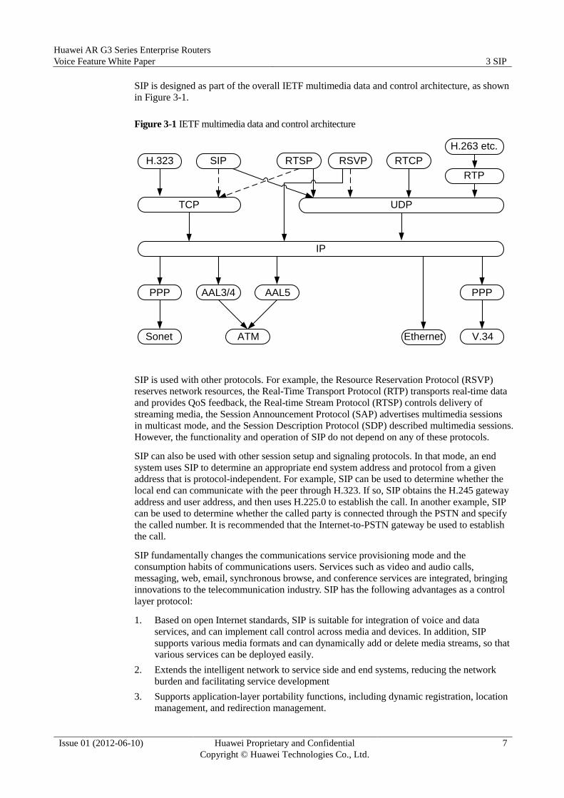
SIP is designed as part of the overall IETF multimedia data and control architecture, as shown
in Figure 3-1.
Figure 3-1 IETF multimedia data and control architecture
H.323 SIP RTSP RSVP RTCP
H.263 etc.
RTP
TCP UDP
IP
PPP PPPAAL3/4 AAL5
Sonet ATM Ethernet V.34
SIP is used with other protocols. For example, the Resource Reservation Protocol (RSVP)
reserves network resources, the Real-Time Transport Protocol (RTP) transports real-time data
and provides QoS feedback, the Real-time Stream Protocol (RTSP) controls delivery of
streaming media, the Session Announcement Protocol (SAP) advertises multimedia sessions
in multicast mode, and the Session Description Protocol (SDP) described multimedia sessions.
However, the functionality and operation of SIP do not depend on any of these protocols.
SIP can also be used with other session setup and signaling protocols. In that mode, an end
system uses SIP to determine an appropriate end system address and protocol from a given
address that is protocol-independent. For example, SIP can be used to determine whether the
local end can communicate with the peer through H.323. If so, SIP obtains the H.245 gateway
address and user address, and then uses H.225.0 to establish the call. In another example, SIP
can be used to determine whether the called party is connected through the PSTN and specify
the called number. It is recommended that the Internet-to-PSTN gateway be used to establish
the call.
SIP fundamentally changes the communications service provisioning mode and the
consumption habits of communications users. Services such as video and audio calls,
messaging, web, email, synchronous browse, and conference services are integrated, bringing
innovations to the telecommunication industry. SIP has the following advantages as a control
layer protocol:
1. Based on open Internet standards, SIP is suitable for integration of voice and data
services, and can implement call control across media and devices. In addition, SIP
supports various media formats and can dynamically add or delete media streams, so that
various services can be deployed easily.
2. Extends the intelligent network to service side and end systems, reducing the network
burden and facilitating service development
3. Supports application-layer portability functions, including dynamic registration, location
management, and redirection management.

Huawei AR G3 Series Enterprise Routers
Voice Feature White Paper 3 SIP
Issue 01 (2012-06-10) Huawei Proprietary and Confidential
Copyright © Huawei Technologies Co., Ltd.
8
4. Provides presence/Fork/Subscription features, which facilitate new service development
5. It is simple and scalable.
3.1 SIP Structure
The SIP protocol logically consists of the following elements:
User agent: also called the SIP terminal. It is the end user of the SIP system and is
defined as an application in RFC3261. Based on roles in a session, user agents can be
classified into the user agent client (UAC) and user agent server (UAS). The UAC
initiates a call request, and the UAS responds to the call request.
SIP proxy server: an intermediate device. It can function as a server to parse user names
and function as a client agent to initiate a call request to the next-hop server, which then
determines the next hop address.
SIP register server: an important part in the SIP system. It receives user registration
information and maintains the information into the address database.
Location server: stores and returns user address information. It obtains address
information from the register server or other databases, and then uploads the address
registration information to the location server.
Redirect server: determines paths of call. After obtaining the next hop address, this
server requests the previous-hop user to initiate a request directly to the next hop. At the
same time, this server stops controlling the call. For example, if Bob wants to call Lara
and this request is sent to the redirect server. The redirect server obtains the address of
Lara and returns the address to Bob. Then, Bob can resend the session invitation to the
address.
Actually, functions of the preceding SIP servers are provided by one server. They are only
identified logically. The following figures show interactions between the SIP components.
Interaction between the UA, register server, and location server: registration
Register Server
This is 010-8888.
I am at
010-8888 is at
Location ServerI have made a record.OK. The registration completes.
1 2
34UA
Huawei AR G3 Series Enterprise Routers
Voice Feature White Paper 3 SIP
Issue 01 (2012-06-10) Huawei Proprietary and Confidential
Copyright © Huawei Technologies Co., Ltd.
9
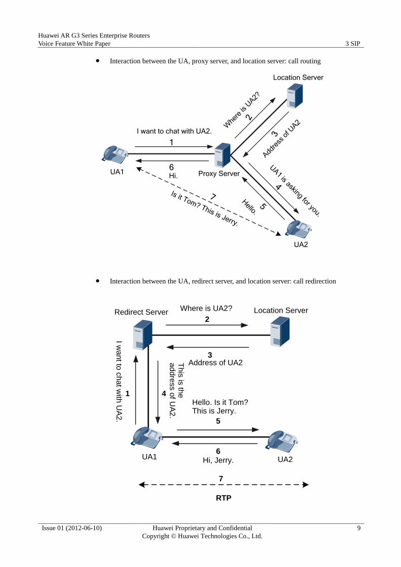
Interaction between the UA, proxy server, and location server: call routing
Proxy Server
I want to chat with UA2.
Location Server
1
UA1
Add
ress
of U
A2
2
Whe
re is
UA2?
3
UA1 is asking for you.
4
5Hello.
6Hi.
Is it Tom? This is Jerry.
7
UA2
Interaction between the UA, redirect server, and location server: call redirection I w
an
t to c
ha
t with
UA
2.
Location Server
1
UA1
Where is UA2?
2
Address of UA23
Th
is is
the
a
dd
ress o
f UA
2.
4
5
Hello. Is it Tom? This is Jerry.
6Hi, Jerry.
7
RTP
Redirect Server
UA2

Huawei AR G3 Series Enterprise Routers
Voice Feature White Paper 3 SIP
Issue 01 (2012-06-10) Huawei Proprietary and Confidential
Copyright © Huawei Technologies Co., Ltd.
10
3.2 SIP Messages
SIP messages are encoded in text format. There are two types of SIP messages: request and
response.
RFC 3261 defines the following SIP request messages:
INVITE: invites a user to a call.
ACK: acknowledges a response message.
OPTIONS: negotiates communication capabilities with the peer.
BYE: terminates a session.
CANCEL: cancels a session establishment.
REGISTER: registers user location information with a registrar server.
SIP response messages are sent in response to request messages, informing calling parties of
call or registration results. Status codes identify the types of response messages. A status code
is a 3-digit integer. The leftmost digit indicates the response message type, and the other two
digits provide additional information, such as how a received request message is processed.
RFC 3261 defines the following status codes:
100 to 199: provisional. A request has been received and is being processed.
200 to 299: success. A request has been successfully processed.
300 to 399: redirection. Further action needs to be taken to complete the request.
400 to 499: client error. A request contains incorrect syntax or cannot be processed by the
server.
500 to 599: server error. The server failed to process a valid request.
600 to 699: global failure. A request cannot be processed by any servers.
3.3 User Registration Process
Before a SIP user initiates a call, the user must register user information (for example,
mapping between the domain name and the IP address) on the home network. The registration
process can be implemented in non-authentication mode or authentication mode. After the
system is powered on or a user is added, the user registration process starts.

Huawei AR G3 Series Enterprise Routers
Voice Feature White Paper 3 SIP
Issue 01 (2012-06-10) Huawei Proprietary and Confidential
Copyright © Huawei Technologies Co., Ltd.
11
Registration Process in Non-authentication Mode
Figure 3-2 Registration process in non-authentication mode
SIP AG IMS Core
Register
Response 200
As shown in Figure 3-2, the SIP AG sends a Register message to the IMS Core for each user.
The Register message contains information such as the user identity. When receiving the
Register message, the IMS Core checks whether the user is configured in the IMS. If the user
is configured, the IMS Core returns a Response-200 message to the SIP AG. If the user is not
configured, the IMS Core returns a Response-403 message to reject the registration.
The AR supports individual registration and group registration. In individual registration
mode, users register on the IMS core individually through SIP AT0 trunks. In group
registration mode, multiple users can register on the IMS core together, which reduces the
number of register messages and avoids registration storms.
Registration Process in Authentication Mode
Figure 3-3 Registration process in authentication mode
SIP AG IMS Core
Register
Response 401/407
Register
Response 200
Huawei AR G3 Series Enterprise Routers
Voice Feature White Paper 3 SIP
Issue 01 (2012-06-10) Huawei Proprietary and Confidential
Copyright © Huawei Technologies Co., Ltd.
12
As shown in Figure 3-3, the SIP AG sends a Register message to the IMS Core for each user.
The Register message contains information such as the user identity.
When receiving the Register message, the IMS Core queries and learns that this SIP AG
registration requires authentication. Then, the IMS Core returns Response-401/407, which
contains information such as the key and encryption method. The SIP AG encrypts the user
name and password with the key, and sends them in a Register message to the IMS Core. The
IMS Core decrypts the Register message and checks whether the user name and password are
correct. If they are correct, the IMS Core returns Response-200.
The AR supports the DIGEST MD5, DIGEST MD5-SESS, and AkAv1-MD5 algorithms for
authentication and encryption.
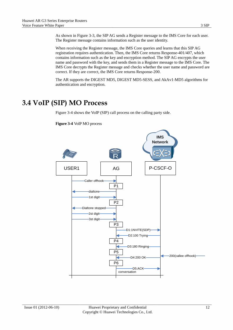
3.4 VoIP (SIP) MO Process
Figure 3-4 shows the VoIP (SIP) call process on the calling party side.
Figure 3-4 VoIP MO process
200(callee offhook)
Caller offhook
dialtone
P1
1st digit
P2
P4
P5
P6
P3
Dialtone stopped
2st digit
3st digit
D1:1NVITE(SDP)
D2:100 Trying
D3:180 Ringing
D4:200 OK
D5:ACKconversation
USER1 AG P-CSCF-O
IMS
Network

Huawei AR G3 Series Enterprise Routers
Voice Feature White Paper 3 SIP
Issue 01 (2012-06-10) Huawei Proprietary and Confidential
Copyright © Huawei Technologies Co., Ltd.
13
P1: The AG receives the pick-up message from the calling party and plays the dial tone
for the calling party.
P2: When receiving the first dial number, the AG stops the dial tone and matches the
number with the digitmaps.
P3: After receiving N numbers, the AG detects that the numbers match a digitmap. Then
the AG constructs an Invite message and sends it to the P-CSCF.
P4: When receiving 100 Trying, the AG learns that the peer has received the Invite
message. Then the AG stops the process of retransmitting the Invite message.
P5: The AG receives 180 Ringing, indicating that the phone of the called party rings. The
AG plays the RBT for the calling party.
P6: The AG receives 200 OK message, indicating that the called party has picked up the
phone. Then the AG stops playing the RBT and changes the flow mode to bidirectional.
The AG constructs an ACK message to the P-CSCF.
Besides normal calls, there are other scenarios. When the calling party initiates a call, the
P-CSCF performs either of the following operations:
If the data about the calling party exists but is not registered, the P-CSCF rejects the call
from the calling party and returns message 403.
If there is no data about the calling party, the P-CSCF rejects the call from the calling
party and returns message 404.
3.5 VoIP (SIP) MT Process
Figure 3-5 shows the VoIP (SIP) call process on the called party side.
Figure 3-5 VoIP (SIP) MT process
ring
P1
P2
P3
Callee offhook
D2:100 Trying
D5:ACK
conversation
D1:INVITE(SDP)
D3:180 Ringing
D4:200 OK
IMS
Network
USER1 AG P-CSCF-T
Huawei AR G3 Series Enterprise Routers
Voice Feature White Paper 3 SIP
Issue 01 (2012-06-10) Huawei Proprietary and Confidential
Copyright © Huawei Technologies Co., Ltd.
14
P1: After receiving an INVITE message from the P-CSCF, the AG constructs a 100
Trying message and sends it to the P-CSCF. The AG locates the called party according to
the P-Called-Party-ID header field, RequestURI, and TO header field carried in the
INVITE message. If the TEL-URI field is used, the header fields can be not used. The
AG can locate the called party according to the phone number in the TEL-URI field.
Then the AG plays the ring tone to the called party. The AG constructs a 180 Ringing
message and sends it to the P-CSCF, notifying that the phone of the called party is
ringing.
P2: After receiving the off-hook message from the called party, the AG stops ringing. In
addition, the AG constructs a 200 OK message and sends it to the P-CSCF, notifying the
called party has picked up the phone.
P3: The AG receives an ACK message and the calling party and the called party talk with
each other.
Besides normal calls, there are other scenarios. When receiving the Invite message, the AG
performs either of the following operations:
If the data about the called party exists but is not registered, the AG rejects the call from
the calling party and returns message 403 to P-CSCF.
If there is no data about the called party, the AG rejects the call from the calling party
and returns message 404 to P-CSCF.
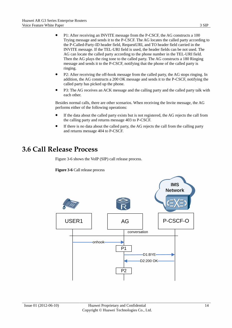
3.6 Call Release Process
Figure 3-6 shows the VoIP (SIP) call release process.
Figure 3-6 Call release process
IMS
Network
USER1 AG P-CSCF-O
P1
P2
onhook
conversation
D2:200 OK
D1:BYE

Huawei AR G3 Series Enterprise Routers
Voice Feature White Paper 3 SIP
Issue 01 (2012-06-10) Huawei Proprietary and Confidential
Copyright © Huawei Technologies Co., Ltd.
15
P1: After receiving the onhook message of the user, the AG constructs a BYE message
and sends it to the P-CSCF to release the DSP resource allocated to the user.
P2: After receiving 200 OK from the P-CSCF, the AG releases the call.
3.7 FoIP (FAX over IP)
Traditional fax is sent and received through the PSTN. Fax services are widely used because
various types of information can be easily transmitted at a high speed.
The International Telegraph and Telephone Consultative Committee (CCITT) defines four fax
machine standards, namely, G1, G2, G3, and G4 fax machines.
G1: low-speed analog fax machines using analog frequency shift keying signals, and in
black and white
G2: medium-speed analog fax machines using analog phase shift keying signals in black
and white; compressed frequency band at a transmission speed double that of G1
G3: high-speed digital fax machines using modulating signals in black and white at a
transmission speed four times that of G1
G4: high-speed digital fax machines for the ISDN network at a speed of 64 kbit/s, using
hybrid fax and telegraph terminals
Due to the limitation of speeds or cables, G1, G2, and G4 fax machines are not widely used.
Only G3 fax machines are commonly used for fax communication. G3 fax machines use a
digital signal processing technology. Image signals are digitalized and compressed in a fax
machine, converted to analog signals by a modem, and finally transmitted to a PSTN switch
through common subscriber lines.
3.7.1 FoIP Overview
Fax over IP (FoIP) sends and receives fax over the Internet. Compared with traditional fax,
FoIP has the following benefits:
Low fee: FoIP fully use the worldwide deployment and low communication fees of the
Internet, and significantly reduces fax fees for enterprises.
High security and QoS: FoIP uses advanced transmission and encryption technologies to
improve the content definition and confidentiality, which are better than those of the
traditional fax and IP telephone fax.
High intelligence: FoIP automatically resends fax in a specified period and returns
success or failure information to the user's email box.
3.7.2 FoIP Transmission Mode
FoIP supports two transmission modes (pass-through and T.38) and two switching modes
(auto-switch and initiated negotiation switch). That is, four fax modes are available:
auto-switch pass-through, auto-switch T.38, negotiation pass-through, and negotiation T.38.
Auto-switch: The AG detects fax signals and selects the transparent or T.38 mode based on
the configuration. In this case, the AG does not need to send any signal to the peer end.
Initiated negotiation: The AG detects fax signals, and then sends a REINVITE message
carrying negotiation parameters to negotiate the codec mode with the peer based on the
configuration.
Huawei AR G3 Series Enterprise Routers
Voice Feature White Paper 3 SIP
Issue 01 (2012-06-10) Huawei Proprietary and Confidential
Copyright © Huawei Technologies Co., Ltd.
16
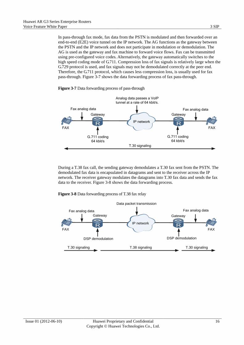
In pass-through fax mode, fax data from the PSTN is modulated and then forwarded over an
end-to-end (E2E) voice tunnel on the IP network. The AG functions as the gateway between
the PSTN and the IP network and does not participate in modulation or demodulation. The
AG is used as the gateway and fax machine to forward voice flows. Fax can be transmitted
using pre-configured voice codes. Alternatively, the gateway automatically switches to the
high speed coding mode of G.711. Compression loss of fax signals is relatively large when the
G.729 protocol is used, and fax signals may not be demodulated correctly at the peer end.
Therefore, the G.711 protocol, which causes less compression loss, is usually used for fax
pass-through. Figure 3-7 shows the data forwarding process of fax pass-through.
Figure 3-7 Data forwarding process of pass-through
FAX FAX
Gateway
T.30 signaling
Gateway
Fax analog data Fax analog data
Analog data passes a VoIP
tunnel at a rate of 64 kbit/s.
IP network
G.711 coding
64 kbit/s
G.711 coding
64 kbit/s
During a T.38 fax call, the sending gateway demodulates a T.30 fax sent from the PSTN. The
demodulated fax data is encapsulated in datagrams and sent to the receiver across the IP
network. The receiver gateway modulates the datagrams into T.30 fax data and sends the fax
data to the receiver. Figure 3-8 shows the data forwarding process.
Figure 3-8 Data forwarding process of T.38 fax relay
FAX FAX
Gateway Gateway
Fax analog data Fax analog data
Data packet transmission
IP network
DSP demodulation DSP demodulation
T.38 signalingT.30 signaling T.30 signaling
Huawei AR G3 Series Enterprise Routers
Voice Feature White Paper 3 SIP
Issue 01 (2012-06-10) Huawei Proprietary and Confidential
Copyright © Huawei Technologies Co., Ltd.
17
3.7.3 Low-Speed Fax and High-Speed Fax
Differences between low-speed fax and high-speed fax are as follows:
Standard: High-speed fax uses the V.8 data transmission process. Low-speed fax uses the
fax process defined by T.30. In addition, some low-speed fax terminals may use earlier
standards.
Rate range: Rate supported by high-speed fax ranges from 2.4 kbit/s to 33.6 kbit/s and
that supported by low-speed fax ranges from 2.4 kbit/s to 14.4 kbit/s.
Uplink transmission mode: High-speed fax uses only the pass-through mode. That is, fax
is transmitted at a high rate from a modem to a gateway. Low-speed fax uses
pass-through or T.38 mode. (T.38 mode does not support the rate of high-speed fax.)
Error correction mode (ECM) requirement: High speed-fax must use the ECM
mode, which is optional for low-speed fax.
DSP EC requirement: High-speed fax requires DSP EC to be disabled (because it has an
echo processing mechanism). Low-speed fax requires EC to be enabled (because it has
no echo processing mechanism).
3.8 MoIP (Modem over Internet Protocol)
A modulator demodulator (modem) is a device that is installed between a personal computer
(PC) and a telephone to convert signals exchanged between them. A PC transmits digital
signals to the modem port. The modem receives the signals and coverts (modulates) them into
analog signals. Then, the signals are processed as normal voice signals in the telephony
system. Signals sent from a telephone to a PC are processed reversely: Analog signals are
transmitted over telephone lines to a modem, which converts the analog signals to digital
signals, and sends the digital signals to a PC through the modem port.
Modems are used for signal format conversion, including analog to digital conversion and
digital to analog conversion. Other functions of a modem are as follows:
Coverts signal frequency domain, such as the conversion from low-frequency signals to
high-frequency signals and the modulation from digital baseband transmission to analog
channel transmission.
Extracts low-frequency signals from high-frequency signals.
Demodulates digital baseband signals.
Compresses network transmission data.
Controls coding and error correction.
MoIP provides modem services on the IP network or between the IP network and traditional
PSTN network.

Huawei AR G3 Series Enterprise Routers
Voice Feature White Paper 3 SIP
Issue 01 (2012-06-10) Huawei Proprietary and Confidential
Copyright © Huawei Technologies Co., Ltd.
18
3.8.1 MoIP Connection Type
Same as VoIP, MoIP supports the gateway-based PSTN-IP-PSTN network structure and
PSTN-IP network structure.
Modem communication includes modulation at the physical layer, error correction at the link
layer, and data compression at upper layers. Based on the ways gateways process data of
different layers, the following MoIP connection types are available:
0: Gateways do not process signals. Modulated signals are transparently transmitted on
the IP network through VoIP channels.
1: Gateways modulate modem signals but do not perform error correction or
compression, which are performed end to end by terminals.
2: Gateways modulate modem signals and correct errors, but do not compress data.
3: Gateways on both sides modulate signals, correct errors, and compress data. That is, a
gateway decompresses and recompresses modem signals, and then sends signals to the IP
network. The other gateway performs conversely.
4: Gateways modulate modem signals, correct errors, and compress data. Each gateway
is responsible for the compression and error correction at a certain direction.
The SIP-based modem can also adopt the auto-switch and initiated negotiation modes.
Transparent transmission modems working in initiated negotiation mode can be indicated by
one of the following types:
a=Modem: This transparent transmission modem mode using G.711 is proposed by
China Telecom.
a=silenceSupp:off: This transparent transmission modem mode using G.711 is proposed
in draft-ietf-sipping-realtimefax-01.txt.
a=gpmd:99 vbd=yes: The support of voice band data (VBD) is defined in V.152.

Huawei AR G3 Series Enterprise Routers
Voice Feature White Paper 4 Basic IP PBX Services
Issue 01 (2012-06-10) Huawei Proprietary and Confidential
Copyright © Huawei Technologies Co., Ltd.
19
4 Basic IP PBX Services
IP PBX uses an integrated communication system. Through the telecommunications network
and Internet, only voice, fax, data, and video services can be provided by a single device. A
middle- or small-scale call center can be established, with low costs. By using the network
software and hardware, IP PBX improves the working efficiency and saves communication
costs.
4.1 FXS Access
Foreign exchange station (FXS) access is analog access. FXS implements connection between
a PSTN network and an IP network under the IP PBX architecture and provides PSTN
services.
Figure 4-1 shows the FXS implementation.
Huawei AR G3 Series Enterprise Routers
Voice Feature White Paper 4 Basic IP PBX Services
Issue 01 (2012-06-10) Huawei Proprietary and Confidential
Copyright © Huawei Technologies Co., Ltd.
20
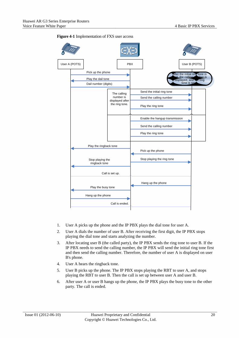
Figure 4-1 Implementation of FXS user access
User A (POTS) PBX User B (POTS)
Pick up the phone
Play the dail tone
After the initial ring tone is sent, the calling number is
displayed, and the ring tone is sent.
The calling
number is
displayed after
the ring tone.
Send the initial ring tone
Send the calling number
Play the ring tone
Enable the hangup transmission
Send the calling number
Play the ring tone
Play the ringback tone
Dail number (digits)
Pick up the phone
Stop playing the ring toneStop playing the
ringback tone
Call is set up.
Hang up the phone
Play the busy tone
Hang up the phone
Call is ended.
1. User A picks up the phone and the IP PBX plays the dial tone for user A.
2. User A dials the number of user B. After receiving the first digit, the IP PBX stops
playing the dial tone and starts analyzing the number.
3. After locating user B (the called party), the IP PBX sends the ring tone to user B. If the
IP PBX needs to send the calling number, the IP PBX will send the initial ring tone first
and then send the calling number. Therefore, the number of user A is displayed on user
B's phone.
4. User A hears the ringback tone.
5. User B picks up the phone. The IP PBX stops playing the RBT to user A, and stops
playing the RBT to user B. Then the call is set up between user A and user B.
6. After user A or user B hangs up the phone, the IP PBX plays the busy tone to the other
party. The call is ended.

Huawei AR G3 Series Enterprise Routers
Voice Feature White Paper 4 Basic IP PBX Services
Issue 01 (2012-06-10) Huawei Proprietary and Confidential
Copyright © Huawei Technologies Co., Ltd.
21
4.2 FXO Access
A foreign exchange office (FXO) accesses a PSTN network through a narrowband port and
common twisted pairs.
4.2.1 FXO as the Calling Party
Figure 4-2 shows the implementation of a call in which the user on the FXO port functions as
the calling party.
Figure 4-2 Implementation of a call in which the user on the FXO port functions as the calling
party
(POTS) User A PBX (AT0) AN
OffHook
Play DialTone
Dial Num
Number analysis
succeeds
OffHook
Play DialTone
Dial Num
Play Ringback Tone
Play Ringback Tone
Session is
set up
Called user picks
up the phone
1. The calling POTS user picks up the phone, hears the dial tone, and dials the called
number.
2. The IP PBX analyzes the number and finds that the outgoing call is made through the
FXO port. Then the IP PBX simulates offhook.
3. The IP PBX plays a dial tone to the FXO port, and determines whether to add a call
prefix to the called number according to the configuration.
Huawei AR G3 Series Enterprise Routers
Voice Feature White Paper 4 Basic IP PBX Services
Issue 01 (2012-06-10) Huawei Proprietary and Confidential
Copyright © Huawei Technologies Co., Ltd.
22
4. If a prefix needs to be added, the IP PBX sends the configured prefix to the switch, and
several seconds later sends the called number to the AN and performs step 6.
5. If no call prefix needs to be added, the PBX sends the called number to the AN.
6. The AN analyzes the received number to locate the called POTS user, and plays the
ringback tone to the FXO port.
7. If the called POTS user picks up the phone, the AN sends a polarity reversal signal to the
FXO port. The calling and called POTS users start the conversation.
8. The calling or called party hangs up to end the call.
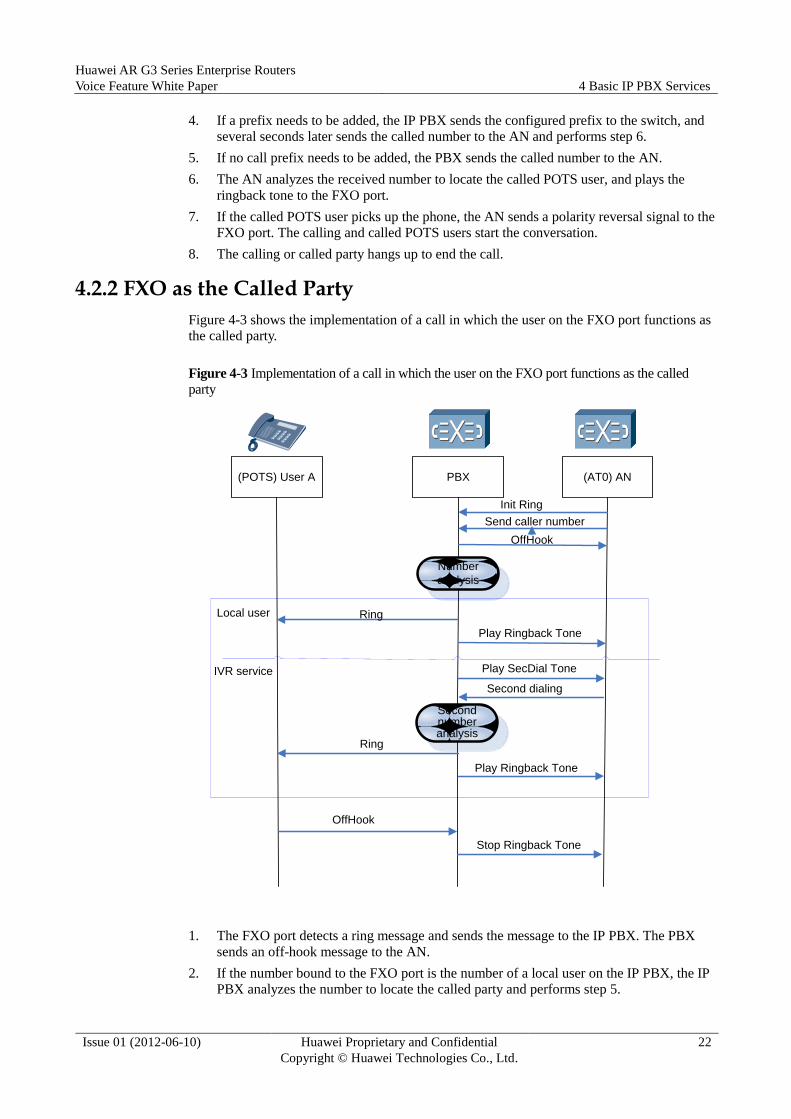
4.2.2 FXO as the Called Party
Figure 4-3 shows the implementation of a call in which the user on the FXO port functions as
the called party.
Figure 4-3 Implementation of a call in which the user on the FXO port functions as the called
party
(POTS) User A PBX (AT0) AN
Init Ring
Send caller number
Number
analysis
Local user Ring
Play Ringback Tone
IVR service Play SecDial Tone
Second dialing
Second number analysis
Ring
Play Ringback Tone
OffHook
Stop Ringback Tone
OffHook
1. The FXO port detects a ring message and sends the message to the IP PBX. The PBX
sends an off-hook message to the AN.
2. If the number bound to the FXO port is the number of a local user on the IP PBX, the IP
PBX analyzes the number to locate the called party and performs step 5.

Huawei AR G3 Series Enterprise Routers
Voice Feature White Paper 4 Basic IP PBX Services
Issue 01 (2012-06-10) Huawei Proprietary and Confidential
Copyright © Huawei Technologies Co., Ltd.
23
3. If the number bound to the FXO port is an IVR number of the IP PBX, the IP PBX plays
the two-stage dial tone to the calling party through the FXO port and waits for the calling
party to dial the extension number.
4. The calling party dials the extension number. The PBX analyzes the called number to
locate the called party and performs step 6.
5. The IP PBX sends a ring message to the called party and plays the RBT to the calling
party through the FXO port.
6. After the called party picks up the phone, the PBX stops the ringback tone. The calling
and called parties start the conversation.
7. The calling or called party hangs up to end the call.
4.3 E1/PRI Access
4.3.1 ISDN Signaling
The Integrated Services Digital Network (ISDN) is a set of international communications
standards for digital telephone networks, and a typical circuit-switched telephone network
system.
ISDN supports various services including calls, video phones, data communication, and video
conferences by transmitting and processing voices, faxes, data, and images on a unified digital
network. Before the emergence of broadband access, ISDN is widely used for high speed
network access because of its faster speed than dial-up access. A relatively comprehensive
ISDN network is deployed in many areas.
ISDN can be classified into narrowband ISDN and broadband ISDN. Narrowband ISDN uses
the basic rate interface (BRI, 2B+D, 144 kbit/s) and primary rate interface (PRI, 30B+D, 2
Mbit/s). The BRI includes two 64 kbit/s bearer channels (B channels) and one 16 kbit/s
signaling channel (D channel or delta channel). The B channels are used for the transmission
of voice, data, and image, and the D channel is used for the transmission of signaling and
packet information.
With the emergence and wide application of VoIP, VoIP gateways are required to process
ISDN signaling messages. These messages and their functions are defined in ITU-T
Recommendation Q.931. Q.931, the network layer protocol of the telecommunication system,
mainly sets up and maintains calls on the ISDN, and terminates the logical network
connection between two devices.
ISDN Q.931 messages manage the connection on ISDN B channels. These messages can also
be modified and used in the Frame Relay and ATM UNIs to set up calls, or be used on NNIs
to provide services between networks. These messages are listed in Table 4-1 and brief
introductions to certain major messages are provided.
Table 4-1 ISDN layer 3 messages
ISDN Layer 3 Messages
NOTE
Message application varies with vendors and countries.
Call establishment messages HOLD
NOTIFY HOLD ACKNOWLEDGE

Huawei AR G3 Series Enterprise Routers
Voice Feature White Paper 4 Basic IP PBX Services
Issue 01 (2012-06-10) Huawei Proprietary and Confidential
Copyright © Huawei Technologies Co., Ltd.
24
CALL PROCEEDING HOLD REJECT
CONNECT USER INFORMATION
CONNECT ACKNOWLEDGE Miscellaneous messages
PROGRESS CANCEL
SETUP CANCEL ACKNOWLEDGE
SETUP ACKNOWLEDGE CANCEL REJECT
DETACH CONGESTION CONTROL
DISCONNECT FACILITY
RELEASE FACILITY ACKNOWLEDGE
RELEASE COMPLETE FACILITY REJECT
RESTART INFORMATION
RESTART ACK REGISTER
Call information phase messages REGISTER ACKNOWLEDGE
RETRIEVE REGISTER REJECT
RETRIEVE ACKNOWLEDGE STATUS
RETRIEVE REJECT STATUS INQUIRY
NOTIFY: indicates that the called party is notified and the call is in process. This is the
response message to a SET UP message. After the called exchange sends ALERTING to
the called party, this message is sent from the called party to the calling party.
CALL PROCEEDING: sent to the call initiator, indicating that the call establishment has
started. This message also indicates that all mandatory messages for call establishment
are received and no more call establishment messages are accepted. During ISDN
implementation, this message is sent only on the setup initiator side.
CONGESTION CONTROL: used only in a USER INFORMATION message. This
message is used to manage the USER INFORMATION message stream. This message is
seldom used.
CONNECT: invoked faster when the called party picks up the phone. This message is
sent from the called party to the calling party, indicating that the call is received by the
called party.
CONNECT ACK: a response message to CONNECT. This message indicates that the
calling party and called party are authorized to participate in a call.
DISCONNECT: sent when the calling party or called party hangs up the phone. When
this message is sent, the E2E connection on the network is disconnected. Resources
reserved for the connection can be used by other calls.
INFORMATION: sent for more connection-related information by the user or network.
For example, an exchange can invoke this message to provide another exchange with
additional information about the connection.
BULLETIN: used only when a user or network provides connection-related information.
Huawei AR G3 Series Enterprise Routers
Voice Feature White Paper 4 Basic IP PBX Services
Issue 01 (2012-06-10) Huawei Proprietary and Confidential
Copyright © Huawei Technologies Co., Ltd.
25
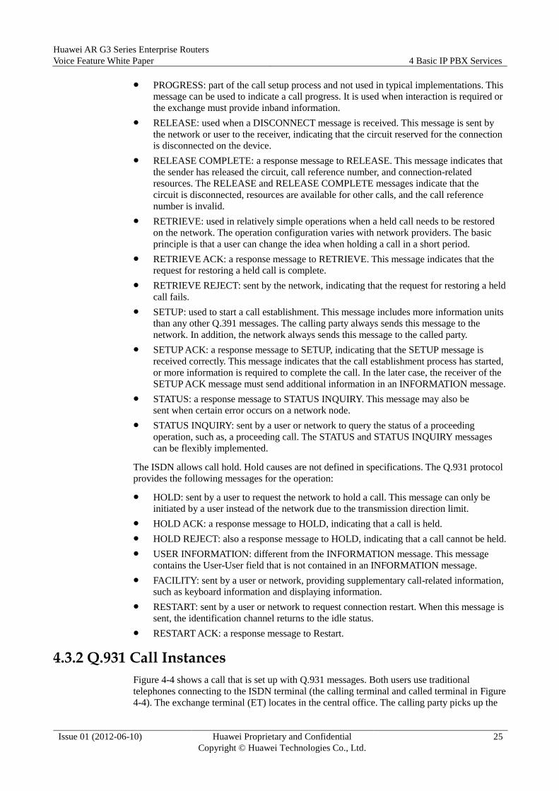
PROGRESS: part of the call setup process and not used in typical implementations. This
message can be used to indicate a call progress. It is used when interaction is required or
the exchange must provide inband information.
RELEASE: used when a DISCONNECT message is received. This message is sent by
the network or user to the receiver, indicating that the circuit reserved for the connection
is disconnected on the device.
RELEASE COMPLETE: a response message to RELEASE. This message indicates that
the sender has released the circuit, call reference number, and connection-related
resources. The RELEASE and RELEASE COMPLETE messages indicate that the
circuit is disconnected, resources are available for other calls, and the call reference
number is invalid.
RETRIEVE: used in relatively simple operations when a held call needs to be restored
on the network. The operation configuration varies with network providers. The basic
principle is that a user can change the idea when holding a call in a short period.
RETRIEVE ACK: a response message to RETRIEVE. This message indicates that the
request for restoring a held call is complete.
RETRIEVE REJECT: sent by the network, indicating that the request for restoring a held
call fails.
SETUP: used to start a call establishment. This message includes more information units
than any other Q.391 messages. The calling party always sends this message to the
network. In addition, the network always sends this message to the called party.
SETUP ACK: a response message to SETUP, indicating that the SETUP message is
received correctly. This message indicates that the call establishment process has started,
or more information is required to complete the call. In the later case, the receiver of the
SETUP ACK message must send additional information in an INFORMATION message.
STATUS: a response message to STATUS INQUIRY. This message may also be
sent when certain error occurs on a network node.
STATUS INQUIRY: sent by a user or network to query the status of a proceeding
operation, such as, a proceeding call. The STATUS and STATUS INQUIRY messages
can be flexibly implemented.
The ISDN allows call hold. Hold causes are not defined in specifications. The Q.931 protocol
provides the following messages for the operation:
HOLD: sent by a user to request the network to hold a call. This message can only be
initiated by a user instead of the network due to the transmission direction limit.
HOLD ACK: a response message to HOLD, indicating that a call is held.
HOLD REJECT: also a response message to HOLD, indicating that a call cannot be held.
USER INFORMATION: different from the INFORMATION message. This message
contains the User-User field that is not contained in an INFORMATION message.
FACILITY: sent by a user or network, providing supplementary call-related information,
such as keyboard information and displaying information.
RESTART: sent by a user or network to request connection restart. When this message is
sent, the identification channel returns to the idle status.
RESTART ACK: a response message to Restart.
4.3.2 Q.931 Call Instances
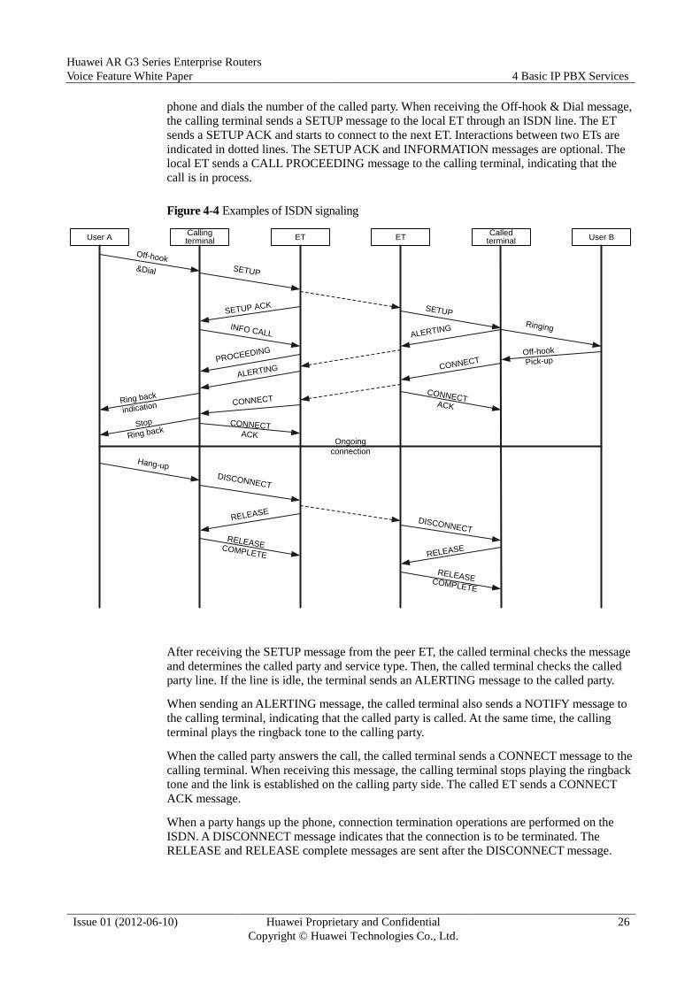
Figure 4-4 shows a call that is set up with Q.931 messages. Both users use traditional
telephones connecting to the ISDN terminal (the calling terminal and called terminal in Figure
4-4). The exchange terminal (ET) locates in the central office. The calling party picks up the
Huawei AR G3 Series Enterprise Routers
Voice Feature White Paper 4 Basic IP PBX Services
Issue 01 (2012-06-10) Huawei Proprietary and Confidential
Copyright © Huawei Technologies Co., Ltd.
26
phone and dials the number of the called party. When receiving the Off-hook & Dial message,
the calling terminal sends a SETUP message to the local ET through an ISDN line. The ET
sends a SETUP ACK and starts to connect to the next ET. Interactions between two ETs are
indicated in dotted lines. The SETUP ACK and INFORMATION messages are optional. The
local ET sends a CALL PROCEEDING message to the calling terminal, indicating that the
call is in process.
Figure 4-4 Examples of ISDN signaling
User ACalling terminal User B
Called terminalET ET
CONNECT
SETUP
SETUP
Ringing
SETUP ACK
INFO CALL
PROCEEDING
ALERTING
ALERTING
Ring back
indication
Stop
Ring backCONNECT
ACK
CONNECT
CONNECTACK
Ongoing
connection
Hang-up
DISCONNECT
DISCONNECT
Off-hook
Pick-up
RELEASE
RELEASECOMPLETE
RELEASE
RELEASECOMPLETE
Off-hook&Dial
After receiving the SETUP message from the peer ET, the called terminal checks the message
and determines the called party and service type. Then, the called terminal checks the called
party line. If the line is idle, the terminal sends an ALERTING message to the called party.
When sending an ALERTING message, the called terminal also sends a NOTIFY message to
the calling terminal, indicating that the called party is called. At the same time, the calling
terminal plays the ringback tone to the calling party.
When the called party answers the call, the called terminal sends a CONNECT message to the
calling terminal. When receiving this message, the calling terminal stops playing the ringback
tone and the link is established on the calling party side. The called ET sends a CONNECT
ACK message.
When a party hangs up the phone, connection termination operations are performed on the
ISDN. A DISCONNECT message indicates that the connection is to be terminated. The
RELEASE and RELEASE complete messages are sent after the DISCONNECT message.

Huawei AR G3 Series Enterprise Routers
Voice Feature White Paper 4 Basic IP PBX Services
Issue 01 (2012-06-10) Huawei Proprietary and Confidential
Copyright © Huawei Technologies Co., Ltd.
27
4.3.3 IP PBX Access to the PSTN
A PBX can interoperate with a PSTN network or another PBX through an E1 port or a PRI
according to the Q.931 protocol to interconnect an intranet with a public network.
Figure 4-5 shows the implementation.
Figure 4-5 Implementation of E1/PRI relay features
PBX IPPBX PSTN
SETUP
SETUP
ACKNOWLEDGE
Number analysis
succeeds.
CONNECT
CALL PROCEEDING
ALERTING
CALL PROCEEDING
Session is
set up.
CONNECT ACKNOWLEDGE
SETUP
ALERTING
CONNECT
CONNECT ACKNOWLEDGE
1. User A (a downstream PBX user) picks up the phone and dials the number of user B (a
PSTN user). Through the E1/PRI port, the IP PBX receives a SETUP message that
contains the number of user B.
2. The IP PBX analyzes the number of user B, and selects the E1/PRI port as the port for
sending a SETUP message (containing the number of user B) to the PSTN.
Huawei AR G3 Series Enterprise Routers
Voice Feature White Paper 4 Basic IP PBX Services
Issue 01 (2012-06-10) Huawei Proprietary and Confidential
Copyright © Huawei Technologies Co., Ltd.
28
3. After successfully analyzing the number, the PSTN sends a CALL PROCEEDING
message to the IP PBX, indicating that the number of user B is successfully analyzed.
Then, a call is set up between the PSTN and the IP PBX.
4. The IP PBX sends a CALL PROCEEDING message to the downstream PBX, indicating
that a call is being set up.
5. The PSTN sends an ALERTING message to the IP PBX, indicating that the phone of
user B starts to ring.
6. The IP PBX sends an ALERTING message to the downstream PBX. Then, user A hears
the RBT.
7. User B picks up the phone. Then, the PSTN sends a CONNECT message to the IP PBX,
indicating that user B (the called party) has accepted the call.
8. The IP PBX sends a CONNECT message to the downstream PBX. Then, user A stops
hearing the RBT.
9. The downstream PBX sends a CONNECT ACKNOWLEDGE message to the IP PBX,
indicating that user A (the calling party) answers the call.
10. The IP PBX sends a CONNECT ACKNOWLEDGE message to the PSTN, indicating
that user A and user B are engaged in the call.
4.4 SIP UE Access
In SIP UE access, a software terminal (SIP UE) using SIP accesses the IP PBX and
registers with the IP PBX through the IP network, and uses the services provided by the IP
PBX.
A SIP UE must register with the SIP proxy server when initiating the first call. A SIP
registration process consists of three stages: SIP UE registration, re-registration, and
deregistration. The SIP UE can be registered with or without authentication. Chapter 3 "SIP"
describes the VoIP registration process. This section describes only the registration
process with authentication.

Huawei AR G3 Series Enterprise Routers
Voice Feature White Paper 4 Basic IP PBX Services
Issue 01 (2012-06-10) Huawei Proprietary and Confidential
Copyright © Huawei Technologies Co., Ltd.
29
4.4.1 SIP UE Registration
Figure 4-6 shows the implementation of SIP UE registration.
Figure 4-6 Implementation of SIP UE registration
SIPUE IPPBX
Register(PrivateId)
Register-401(WWW-Authenticate)
Registration
succeeds
Register(PrivateId, Authorization)
Register-200(PublicId)
1. The SIP UE sends a Register message (containing the registration account) to the IP
PBX to initiate registration.
2. The IP PBX finds that the Register message does not contain the authentication
information, so the IP PBX sends a Register-401 message. The Register-401 message
contains the WWW-Authenticate header.
3. The SIP UE sends a Register message containing the registration account and the
Authorization header to the IP PBX again to initiate registration.
4. The IP PBX checks the authentication information of the SIP UE and sends a
Register-200 message after authentication is successful. The Register-200 message
contains the PublicId to be used by the SIP UE.

Huawei AR G3 Series Enterprise Routers
Voice Feature White Paper 4 Basic IP PBX Services
Issue 01 (2012-06-10) Huawei Proprietary and Confidential
Copyright © Huawei Technologies Co., Ltd.
30
4.4.2 Process of a Call Between SIP UEs
Figure 4-7 shows the process of a call between two SIP UEs.
Figure 4-7 Process of a call between two SIP UEs
SIP UE (calling party) PBX
INVITE
INVITE-180
SIP UE (called party)
INVITE
INVITE-180
The called party hears
the ring tone.
The calling party hears the ringback tone.
The called party picks up
the phone.
INVITE-200
INVITE-200
INVITE-ACK
INVITE-ACK
Session is set up.
The calling party hangs
up the phone.
BYE
BYE
The called party hears
the busy tone.
BYE-200
BYE-200
The called party hangs
up the phone.

Huawei AR G3 Series Enterprise Routers
Voice Feature White Paper 4 Basic IP PBX Services
Issue 01 (2012-06-10) Huawei Proprietary and Confidential
Copyright © Huawei Technologies Co., Ltd.
31
1. The calling SIP UE sends an INVITE message containing the called number to the IP
PBX.
2. The IP PBX locates the called SIP UE and sends an INVITE message to this SIP UE.
3. The called SIP UE rings and sends an INVITE-180 response message to the IP PBX.
4. The IP PBX forwards the INVITE-180 response message of the called SIP UE to the
calling SIP UE. Then, the calling party hears the RBT.
5. The called party picks up the phone, and the called SIP UE sends an INVITE-200
response message to the IP PBX.
6. The IP PBX forwards the INVITE-200 response message of the called SIP UE to the
calling SIP UE.
7. The calling SIP UE sends an INVITE-ACK message to the IP PBX.
8. The IP PBX forwards the INVITE-ACK message to the called SIP UE.
9. The calling and called parties start the conversation.
10. The calling party hangs up the phone, and the calling SIP UE sends a BYE message to
the IP PBX.
11. The IP PBX forwards the BYE message to the called SIP UE, and the called party hears
the busy tone.
12. The called SIP UE sends a BYE-200 message to the IP PBX.
13. The IP PBX forwards the BYE-200 message to the calling SIP UE.
14. The called party hangs up the phone and the call is ended.
4.5 Access to the IMS Through SIP
A user can access the IMS through SIP with registration or without registration.
Access without registration is easy and commonly used. This section describes only access to
the IMS through SIP with registration.

Huawei AR G3 Series Enterprise Routers
Voice Feature White Paper 4 Basic IP PBX Services
Issue 01 (2012-06-10) Huawei Proprietary and Confidential
Copyright © Huawei Technologies Co., Ltd.
32
4.5.1 Access to the IMS Through SIP with Registration
Figure 4-8 shows the process of registration with the IMS through SIP.
Figure 4-8 Registration with the IMS through SIP
IPPBX IMS
Register(PrivateId)
Register-401(WWW-Authenticate)
Registration
succeeds
Register(PrivateId, Authorization)
Register-200(PublicId)
1. The IP PBX sends a registration message containing the registration account to the IMS
to initiate registration.
2. The IMS finds that the Register message does not contain the authentication information,
so the IMS sends a Register-401 message containing the WWW-Authenticate header.
3. The IP PBX sends a Register message containing the registration account and the
Authorization header to the IMS again to initiate registration.
4. The IMS checks the authentication information of the IP PBX and sends a Register-200
message after authentication is successful. The Register-200 message contains the
PublicId to be used by the IP PBX.

Huawei AR G3 Series Enterprise Routers
Voice Feature White Paper 4 Basic IP PBX Services
Issue 01 (2012-06-10) Huawei Proprietary and Confidential
Copyright © Huawei Technologies Co., Ltd.
33
4.5.2 Calling and Called Parties Access to the IMS Through SIP
Figure 4-9 shows the call process in the IMS where SIP is used.
Figure 4-9 Call process in the IMS where SIP is used
IPPBX IMS
INVITE
INVITE-180
Called party (SIP
UE)
INVITE
INVITE-180
The called party hears the
ring tone.
The called party picks up
the phone.
INVITE-200
INVITE-200
INVITE-ACK
INVITE-ACK
Session is set up.
Calling party
(POTS)
Pick up the phone
Play the dial tone
Dial number (digits)
Play the ringback tone
Stop playing the ringback tone
1. The calling party picks up the phone and hears the dial tone played by the IP PBX.
2. The calling party dials the called number. The IP PBX collects all the digits and analyzes
the digits. According to the configuration, the IP PBX identifies the call to be destined
for the IMS network. Then, the IP PBX sends an INVITE message containing the called
number to the IMS.
3. The IMS locates the called party (a SIP UE) and sends an INVITE message to the called
party.
4. The called SIP UE rings and sends an INVITE-180 message to the IMS.
5. The IMS forwards the INVITE-180 message of the called SIP UE to the IP PBX. Then,
the IP PBX plays the RBT to the calling party.
6. The called party picks up the phone, and the called SIP UE sends an INVITE-200
message to the IMS.
7. The IMS forwards the INVITE-200 message of the called SIP UE to the IP PBX.
8. The IP PBX sends an INVITE-ACK message to the IMS.
Huawei AR G3 Series Enterprise Routers
Voice Feature White Paper 4 Basic IP PBX Services
Issue 01 (2012-06-10) Huawei Proprietary and Confidential
Copyright © Huawei Technologies Co., Ltd.
34
9. The IP PMS forwards the INVITE-ACK message to the called SIP UE.
10. The calling and called parties start the conversation.
4.6 PBX Communication Through SIP
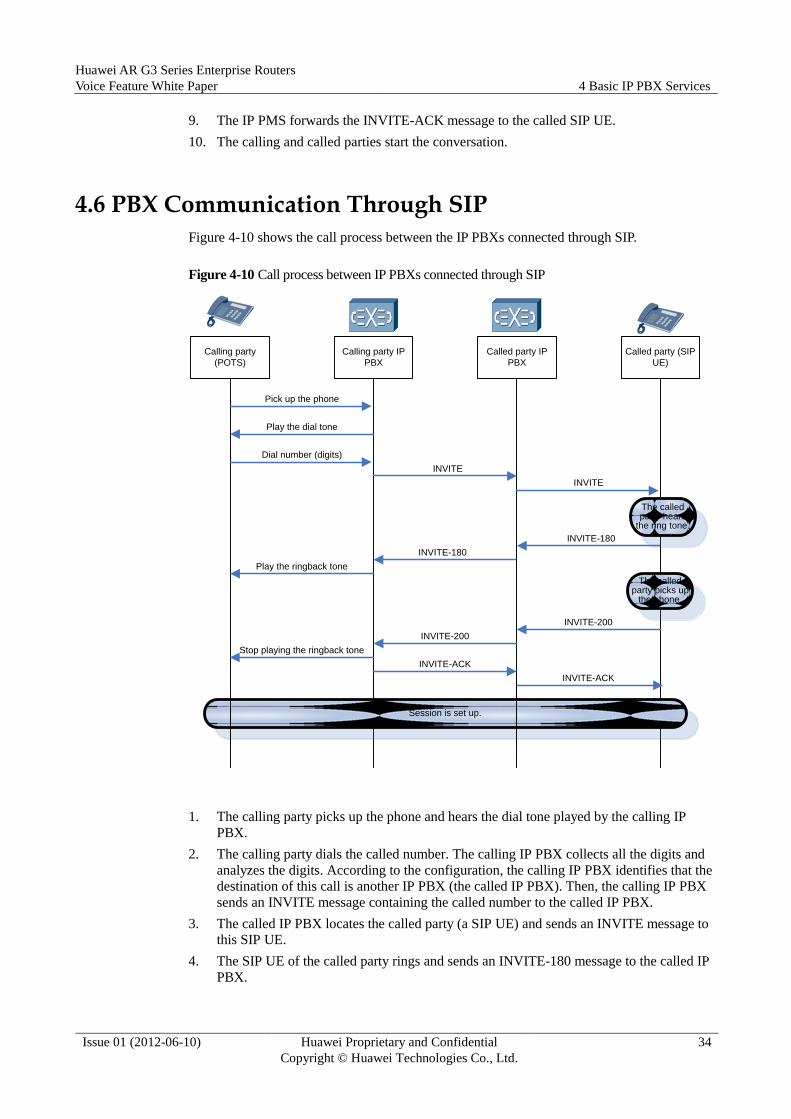
Figure 4-10 shows the call process between the IP PBXs connected through SIP.
Figure 4-10 Call process between IP PBXs connected through SIP
Calling party IP
PBX
Called party IP
PBX
INVITE
INVITE-180
Called party (SIP
UE)
INVITE
INVITE-180
The called party hears
the ring tone.
INVITE-200
INVITE-200
INVITE-ACK
INVITE-ACK
Session is set up.
Calling party
(POTS)
Pick up the phone
Play the dial tone
Dial number (digits)
Play the ringback tone
Stop playing the ringback tone
The called party picks up
the phone.
1. The calling party picks up the phone and hears the dial tone played by the calling IP
PBX.
2. The calling party dials the called number. The calling IP PBX collects all the digits and
analyzes the digits. According to the configuration, the calling IP PBX identifies that the
destination of this call is another IP PBX (the called IP PBX). Then, the calling IP PBX
sends an INVITE message containing the called number to the called IP PBX.
3. The called IP PBX locates the called party (a SIP UE) and sends an INVITE message to
this SIP UE.
4. The SIP UE of the called party rings and sends an INVITE-180 message to the called IP
PBX.
Huawei AR G3 Series Enterprise Routers
Voice Feature White Paper 4 Basic IP PBX Services
Issue 01 (2012-06-10) Huawei Proprietary and Confidential
Copyright © Huawei Technologies Co., Ltd.
35
5. The called IP PBX forwards the INVITE-180 message of the called party to the calling
IP PBX, and then the calling IP PBX plays the RBT to the calling party.
6. The called party picks up the phone, and the SIP UE of the called party sends an
INVITE-200 message to the called IP PBX.
7. The called IP PBX forwards the INVITE-200 message of the called party to the calling
IP PBX.
8. The calling IP PBX sends an INVITE-ACK message to the called IP PBX.
9. The called IP PBX forwards the INVITE-ACK message to the called party.
10. The calling and called parties start the conversation.
4.7 Fax/Modem
With the fax service, the IP PBX carries data transmitted from fax machines on both sides of a
network and manages services. SIP UE and POTS terminals are supported. Data can be
transmitted through the SIP relay or between local users.
Auto-Switch
User A is a POTS user, and user B is a SIP UE user. A call is set up between user A and user B.
The process is similar to that of a telephone call. Then, the fax machine transmits a called
terminal identification (CED) and calling tone (CNG). When an operator presses the Start
button on the fax machine on the receiver side, the CED is transmitted to the peer end,
indicating that the receiver is ready for receiving. After CNG is transmitted on the sender side,
indicating that the sender is ready for transmitting, the voice channel is blocked, and voice
communication cannot proceed. After CED and CNG are detected, A and B automatically
switch to the corresponding codec (T.38, G.711, or CLEARMODE) based on the
configuration, and automatically switch to voice mode when the fax completes.
Locally Initiated Negotiation
User A is a POTS user, and user B is a SIP UE user. User A and user B set up a call
connection. Then they detect CED and CNG and disable the voice channel. User A sends a
Reinvite message to the SIP UE for codec negotiation based on the configuration. When
detecting the fax completion, user A sends an Offer message for negotiation. After the
negotiation, user A switches to voice mode.
Remotely Initiated Negotiation
User A is a POTS user, and user B is a SIP UE user. User A and user B set up a call
connection. The SIP UE detects a fax signal and initiates a negotiation. User A receives the
negotiation message and negotiates codec based on the configuration. When detecting the fax
completion, user A sends an Offer message for negotiation. After the negotiation, user A
switches to voice mode.
4.8 Number Change
By customizing rules, you can change numbers and call prefixes to implement the number
change service. Second number analysis is performed and the second dial tone is played after
a number changes.
Huawei AR G3 Series Enterprise Routers
Voice Feature White Paper 4 Basic IP PBX Services
Issue 01 (2012-06-10) Huawei Proprietary and Confidential
Copyright © Huawei Technologies Co., Ltd.
36
Number Change Type
Numbers can be changed in following modes:
Calling number screening: The calling number is changed when a user initiates a call.
Pre-routing number change: The calling/called number is changed after number analysis
and before route selection. Second number analysis is performed and the second dial
tone is played after a number changes.
Post-routing number change: The calling/called number is changed after route selection.
Calling Number Change
It can be configured in calling number discrimination, number change before route selection,
and number change after route selection. For example, calling number discrimination can be
configured for a voice customer service center as follows: Change the numbers of all outgoing
calls with DN set 0 to 95555. Then, the numbers of all outgoing calls will be changed to
95555.
Called Number Change
It can be configured in number change before route selection and number change after route
selection. For example, the following rule of number change before route selection is
configured for a company: Change the prefix of the called number from 029 to 17909+029.
When a calling party dials 029+called number, the called number will be changed to
17909+toll call number.
DN Set Change
A dial number (DN) set defines a group of numbers that are processed in the same way. A DN
set, a country code, and an area code identify the home area of a user. A DN set and a call
prefix determine the dial plan for a user. DN sets divide a physical network or a device into
multiple logical networks.
It can be configured in calling number discrimination, number change before route selection,
and number change after route selection. The IP PBX can change the DN set during a call to
implement fast reusing of the dialing scheme.
Second Dial Tone Playing
It can be configured in number analysis before route selection. Then, the IP PBX will play the
second dial tone to the user if the user dials an outgoing call prefix.
4.9 Intelligent Routing
Routes are selected based on the user-defined rules. AR routers can select routes based on
5-tuple information (DN set, Centrex group ID, calling number, call prefix, and time range).
Selecting Routes Based on Time Ranges
For example, when the IP PBX is configured with dual upstream routes (route A is SIP IP
trunk and route B is PRA trunk), outgoing calls are directed to route A from 8:00 a.m. to 6:00
p.m. and are directed to route B during other time ranges.
Huawei AR G3 Series Enterprise Routers
Voice Feature White Paper 4 Basic IP PBX Services
Issue 01 (2012-06-10) Huawei Proprietary and Confidential
Copyright © Huawei Technologies Co., Ltd.
37
Selecting Routes Based on User Types
For example, when the IP PBX is configured with dual upstream routes (route A is SIP IP
trunk, and route B is PRA trunk where the voice quality is better), the IP PBX can select route
B for customer groups with a higher priority.

Huawei AR G3 Series Enterprise Routers
Voice Feature White Paper 4 Basic IP PBX Services
Issue 01 (2012-06-10) Huawei Proprietary and Confidential
Copyright © Huawei Technologies Co., Ltd.
38
4.10 CDR
The call detail record (CDR) of users can be queried in real time, and the CDR data can be
analyzed by using a third-party tool. In this way, users can quickly learn the fee of a call in
process and the total fee of the entire call.
Figure 4-11 shows the principle.
Figure 4-11 CDR principle
(SIPUE)
User AIPPBX
(SIPUE)
User B
Invite
180
Invite
180
200 OK
200 OK
ACKACK
Record
CDR startBye Bye
200 OK200 OK
Record
CDR end
1. Set the FTP server address by using a command.
2. User A dials the number of user B. User B picks up the phone and a call is set up.
3. The IP PBX records the CDR start information, including the call start time, calling party
information, and called party information.
4. If either user hangs up the phone to terminate the call, the IP PBX records the CDR end
information and sends the CDR data to the specified FTP server.

Huawei AR G3 Series Enterprise Routers
Voice Feature White Paper 5 IVR Service
Issue 01 (2012-06-10) Huawei Proprietary and Confidential
Copyright © Huawei Technologies Co., Ltd.
39
5 IVR Service
The Interactive Voice Response (IVR) service allows enterprises to customize their IVR menu
and prompt tone, improving user experiences.
When there is an incoming call to the access code of an IVR service, the user is prompted to
dial the extension number or the exchange number. The user can dial the extension number to
enter the start conversation with the called party or dial the exchange number to trigger the
simultaneous ringing service, sequential ringing service, line selection service (selecting a
user based on certain rules). When multiple users call the IVR service, subsequent users wait
in the call queue and hear the call queuing announcement.
5.1 Dialing an Extension Number
An IP PBX can trigger IVR automatic connection. When there is an incoming call to the
access code of an IVR service, the IP PBX connects the call, and the user is prompted to dial
the extension number or the exchange number. This section describes the basic calling process
in which the user dials the extension number.
Assume that user A calls user B by dialing the access code of an IVR service, and users A and
B use SIP UEs. The process is shown in Figure 5-1.
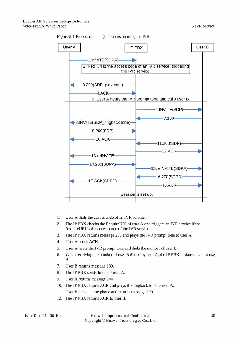
Huawei AR G3 Series Enterprise Routers
Voice Feature White Paper 5 IVR Service
Issue 01 (2012-06-10) Huawei Proprietary and Confidential
Copyright © Huawei Technologies Co., Ltd.
40
Figure 5-1 Process of dialing an extension using the IVR
16.200(SDPD)
1.INVITE(SDPA)
2. Req_uri is the access code of an IVR service, triggering
the IVR service.
4.ACK
8.INVITE(SDP_ringback tone)
9.200(SDP)
14.200(SDPA)
6.INVITE(SDP)
7.180
10.ACK11.200(SDP)
18.ACK
Session is set up.
User A User BIP PBX
3.200(SDP_play tone)
5. User A hears the IVR prompt tone and calls user B.
12.ACK13.reINVITE
15.reINVITE(SDPA)
17.ACK(SDPD)
1. User A dials the access code of an IVR service.
2. The IP PBX checks the RequireURI of user A and triggers an IVR service if the
RequireURI is the access code of the IVR service.
3. The IP PBX returns message 200 and plays the IVR prompt tone to user A.
4. User A sends ACK.
5. User A hears the IVR prompt tone and dials the number of user B.
6. When receiving the number of user B dialed by user A, the IP PBX initiates a call to user
B.
7. User B returns message 180.
8. The IP PBX sends Invite to user A.
9. User A returns message 200.
10. The IP PBX returns ACK and plays the ringback tone to user A.
11. User B picks up the phone and returns message 200.
12. The IP PBX returns ACK to user B.

Huawei AR G3 Series Enterprise Routers
Voice Feature White Paper 5 IVR Service
Issue 01 (2012-06-10) Huawei Proprietary and Confidential
Copyright © Huawei Technologies Co., Ltd.
41
13. The IP PBX sends Reinvite to user A without SDP.
14. User A returns message 200 with SDP.
15. The IP PBX sends Reinvite to user B with the SDP of user A.
16. User B returns message 200 with SDP.
17. The IP PBX returns ACK to user A with the SDP of user B.
18. The IP PBX returns ACK to user B. The session is set up.
5.2 Triggering a Simultaneous Ringing Service
An IP PBX can trigger IVR automatic connection. When there is an incoming call to the
access code of an IVR service, the user is prompted to dial the extension number or the
exchange number. This section describes the process of triggering the simultaneous ringing
service. When a user dials the exchange number, the simultaneous ringing service is triggered,
and all idle phones ring in the group. When a phone is picked up to answer the call, other
phones stop ringing.
Assume that an exchange group consists of users B, C, and D. When user A calls the access
code of an IVR service, the process is shown in Figure 5-2.
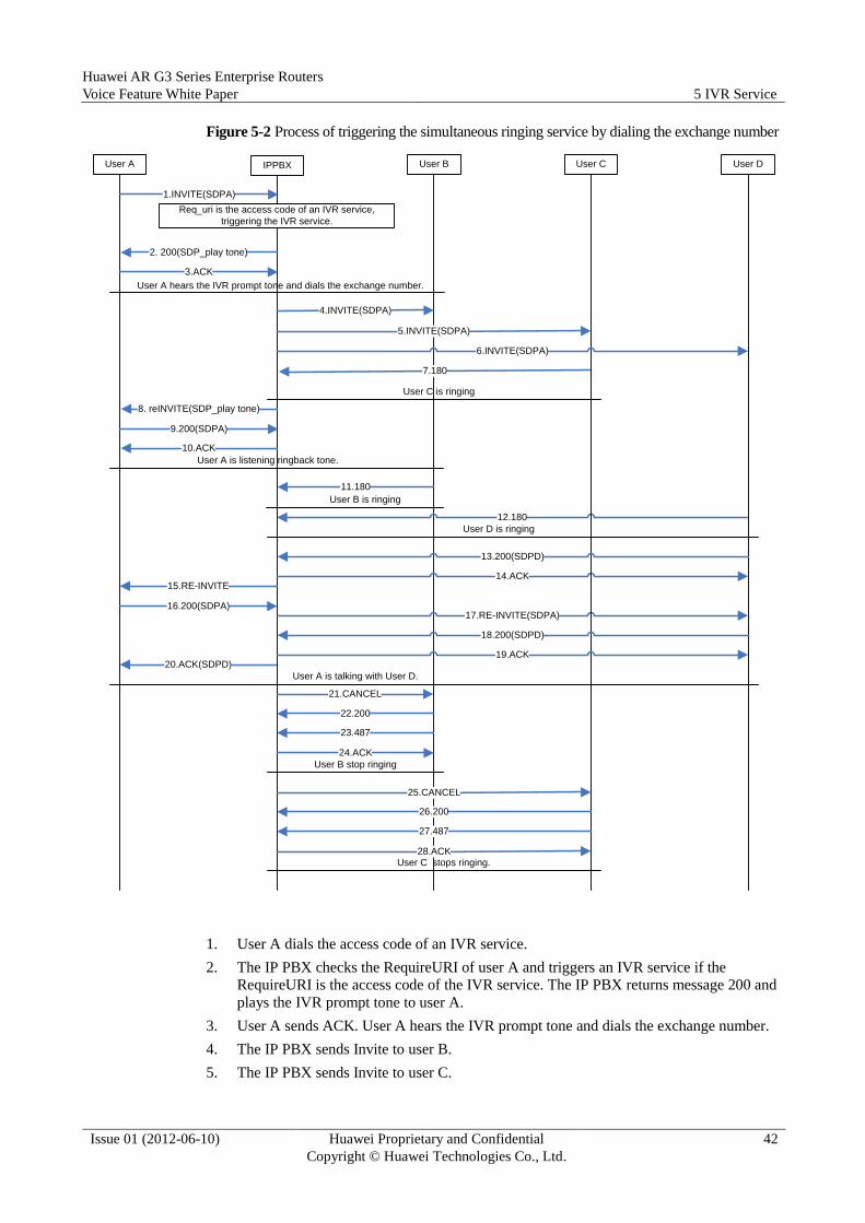
Huawei AR G3 Series Enterprise Routers
Voice Feature White Paper 5 IVR Service
Issue 01 (2012-06-10) Huawei Proprietary and Confidential
Copyright © Huawei Technologies Co., Ltd.
42
Figure 5-2 Process of triggering the simultaneous ringing service by dialing the exchange number
20.ACK(SDPD)
1.INVITE(SDPA)
Req_uri is the access code of an IVR service,
triggering the IVR service.
3.ACK
8. reINVITE(SDP_play tone)
9.200(SDPA)
16.200(SDPA)
4.INVITE(SDPA)
7.180
10.ACK
11.180
21.CANCEL
User B is ringing
User A User BIPPBX
2. 200(SDP_play tone)
User A hears the IVR prompt tone and dials the exchange number.
14.ACK
12.180
17.RE-INVITE(SDPA)
15.RE-INVITE
User C User D
5.INVITE(SDPA)
6.INVITE(SDPA)
User C is ringing
User A is listening ringback tone.
User D is ringing
13.200(SDPD)
18.200(SDPD)
19.ACK
User A is talking with User D.
22.200
23.487
24.ACK
User B stop ringing
25.CANCEL
26.200
27.487
28.ACKUser C stops ringing.
1. User A dials the access code of an IVR service.
2. The IP PBX checks the RequireURI of user A and triggers an IVR service if the
RequireURI is the access code of the IVR service. The IP PBX returns message 200 and
plays the IVR prompt tone to user A.
3. User A sends ACK. User A hears the IVR prompt tone and dials the exchange number.
4. The IP PBX sends Invite to user B.
5. The IP PBX sends Invite to user C.

Huawei AR G3 Series Enterprise Routers
Voice Feature White Paper 5 IVR Service
Issue 01 (2012-06-10) Huawei Proprietary and Confidential
Copyright © Huawei Technologies Co., Ltd.
43
6. The IP PBX sends Invite to user D.
7. User C rings and returns message 180.
8. The IP PBX sends Reinvite to user A.
9. User A returns message 200.
10. The IP PBX returns ACK and plays the ringback tone to user A.
11. User B rings and returns message180.
12. User D rings and returns message 180.
13. User D picks up the phone and returns message 200.
14. The IP PBX returns ACK to user D.
15. The IP PBX sends Reinvite to user A without SDP.
16. User A returns message 200 with SDP.
17. The IP PBX sends Reinvite to user D with the SDP of user A.
18. User D returns message 200 with the SDP of itself.
19. The IP PBX returns ACK to user D.
20. The IP PBX returns ACK to user A with the SDP of user D. The session is set up
between users A and D.
21. The IP PBX sends Cancel to user B to cancel the invite request. When receiving the
message, user B stops ringing.
22. User B returns Cancel-200.
23. User B returns Invite-487.
24. The IP PBX returns an ACK response message to user B.
25. The IP PBX sends Cancel to user C to cancel the invite request. When receiving the
message, user C stops ringing.
26. User C returns Cancel-200.
27. User C returns Invite-487.
28. The IP PBX returns an ACK response message to user C.
5.3 Triggering a Sequential Ringing Service
An IP PBX can trigger IVR automatic connection. When there is an incoming call to the
access code of an IVR service, the user is prompted to dial the extension number or the
exchange number. This section describes the process of triggering the sequential ringing
service. After the sequential ringing service is triggered, all idle phones in the group ring in
sequence. When ringing timeout occurs on the previous phone, the next phone rings. When a
phone is picked up and the call is set up, subsequent phones do not ring.
Assume that the exchange group consists of users B, C, D, and E. Users B and D use SIP UEs
and users C and E use POTS phones. When user A dials the access code of an IVR service,
the process is shown in Figure 5-3.
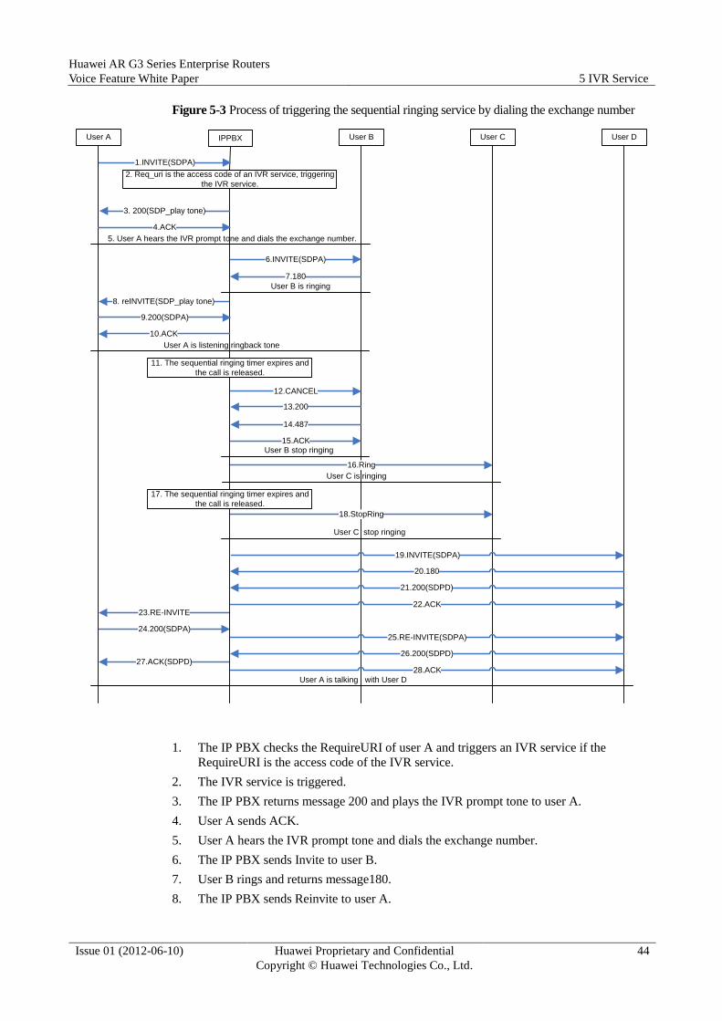
Huawei AR G3 Series Enterprise Routers
Voice Feature White Paper 5 IVR Service
Issue 01 (2012-06-10) Huawei Proprietary and Confidential
Copyright © Huawei Technologies Co., Ltd.
44
Figure 5-3 Process of triggering the sequential ringing service by dialing the exchange number
27.ACK(SDPD)
1.INVITE(SDPA)
2. Req_uri is the access code of an IVR service, triggering
the IVR service.
4.ACK
8. reINVITE(SDP_play tone)
9.200(SDPA)
6.INVITE(SDPA)
10.ACK
13.200
12.CANCEL
User B stop ringing
User A User BIPPBX
3. 200(SDP_play tone)
5. User A hears the IVR prompt tone and dials the exchange number.
16.Ring
18.StopRing
23.RE-INVITE
User C User D
22.ACK
User A is listening ringback tone
20.180
21.200(SDPD)
19.INVITE(SDPA)
24.200(SDPA)25.RE-INVITE(SDPA)
26.200(SDPD)
28.ACK
User A is talking with User D
7.180
User B is ringing
11. The sequential ringing timer expires and
the call is released.
14.487
15.ACK
User C is ringing
17. The sequential ringing timer expires and
the call is released.
User C stop ringing
1. The IP PBX checks the RequireURI of user A and triggers an IVR service if the
RequireURI is the access code of the IVR service.
2. The IVR service is triggered.
3. The IP PBX returns message 200 and plays the IVR prompt tone to user A.
4. User A sends ACK.
5. User A hears the IVR prompt tone and dials the exchange number.
6. The IP PBX sends Invite to user B.
7. User B rings and returns message180.
8. The IP PBX sends Reinvite to user A.
Huawei AR G3 Series Enterprise Routers
Voice Feature White Paper 5 IVR Service
Issue 01 (2012-06-10) Huawei Proprietary and Confidential
Copyright © Huawei Technologies Co., Ltd.
45
9. User A returns message 200.
10. The IP PBX returns ACK and plays the ringback tone to user A.
11. When the sequential ringing timer expires, the call to user B is released.
12. The IP PBX sends Cancel to user B. User B stops ringing.
13. User B returns Cancel-200.
14. User B returns Invite-487.
15. The IP PBX returns ACK.
16. The IP PBX sends Ring to user C. User C rings.
17. When the sequential ringing timer expires, the call to user C is released.
18. The IP PBX sends StopRing to user C. When receiving the message, user C stops
ringing.
19. The IP PBX sends Invite to user D.
20. User D rings and returns message 180.
21. User D picks up the phone and returns message 200.
22. The IP PBX returns ACK to user D.
23. The IP PBX sends Reinvite to user A without SDP.
24. User A returns message 200 with the SDP of itself.
25. The IP PBX sends Reinvite to user D with the SDP of user A.
26. User D returns message 200 with the SDP of itself.
27. The IP PBX returns ACK to user A with the SDP of user D.
28. The IP PBX returns ACK to user D. The session is set up between users A and D.
5.4 Triggering the Line Selection Service
An IP PBX can trigger IVR automatic connection. When there is an incoming call to the
access code of an IVR service, the user is prompted to dial the extension number or the
exchange number. This section describes the process of triggering the line selection service.
When the line selection service is triggered, the IP PBX selects a user from all idle users and
plays the ring tone based on configured line selection rules (ascending, descending, or polling
order of user index numbers). If a user picks up the phone and answers the call, the call is set
up. If the ringing times out, the call is stopped and subsequent users do not ring.
Assume that the exchange group consists of users B, C, D, and E. User B uses SIP UE.
According to the IVR line selection rule, user B is called. When user A dials the access code
of an IVR service, the process is shown in Figure 5-4.
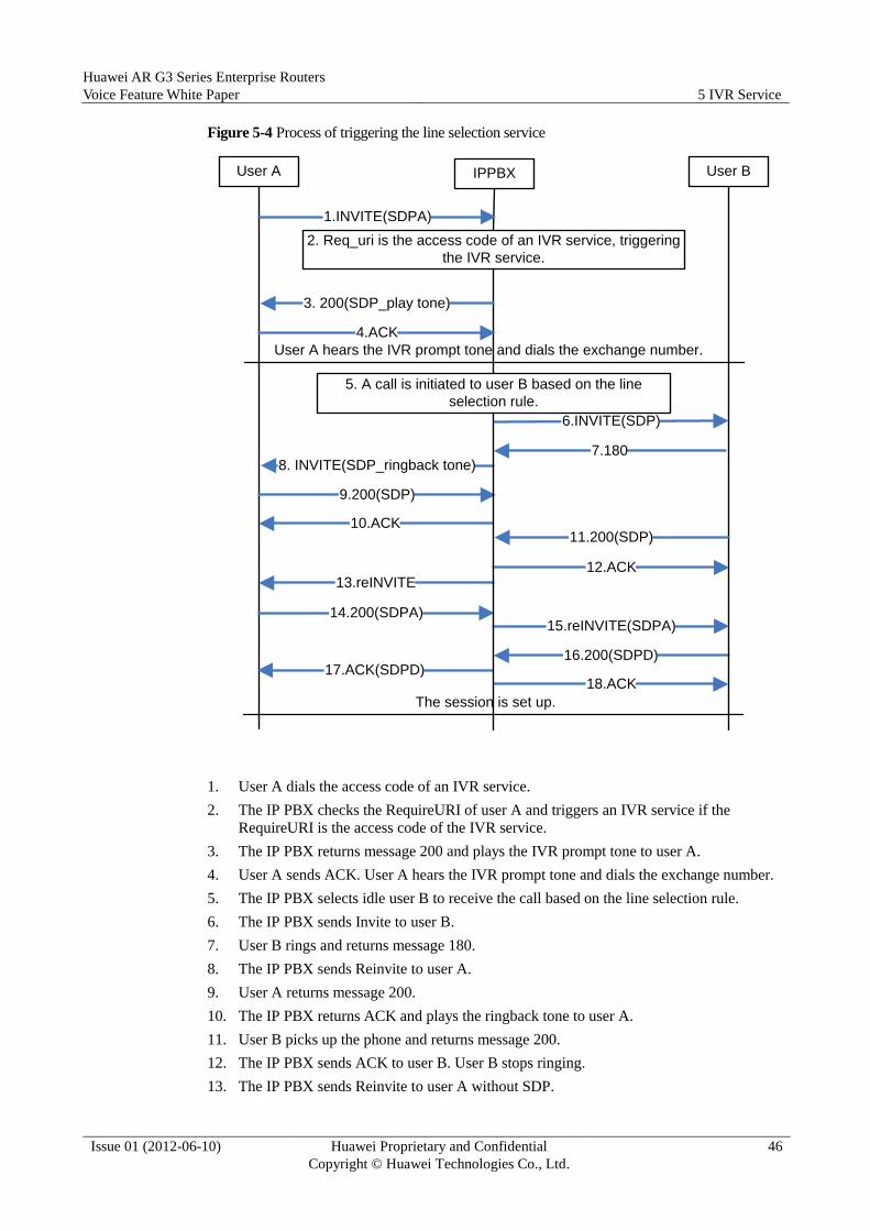
Huawei AR G3 Series Enterprise Routers
Voice Feature White Paper 5 IVR Service
Issue 01 (2012-06-10) Huawei Proprietary and Confidential
Copyright © Huawei Technologies Co., Ltd.
46
Figure 5-4 Process of triggering the line selection service
16.200(SDPD)
1.INVITE(SDPA)
2. Req_uri is the access code of an IVR service, triggering
the IVR service.
4.ACK
8. INVITE(SDP_ringback tone)
9.200(SDP)
14.200(SDPA)
6.INVITE(SDP)
7.180
10.ACK11.200(SDP)
18.ACK
The session is set up.
User A User BIPPBX
3. 200(SDP_play tone)
User A hears the IVR prompt tone and dials the exchange number.
12.ACK13.reINVITE
15.reINVITE(SDPA)
17.ACK(SDPD)
5. A call is initiated to user B based on the line
selection rule.
1. User A dials the access code of an IVR service.
2. The IP PBX checks the RequireURI of user A and triggers an IVR service if the
RequireURI is the access code of the IVR service.
3. The IP PBX returns message 200 and plays the IVR prompt tone to user A.
4. User A sends ACK. User A hears the IVR prompt tone and dials the exchange number.
5. The IP PBX selects idle user B to receive the call based on the line selection rule.
6. The IP PBX sends Invite to user B.
7. User B rings and returns message 180.
8. The IP PBX sends Reinvite to user A.
9. User A returns message 200.
10. The IP PBX returns ACK and plays the ringback tone to user A.
11. User B picks up the phone and returns message 200.
12. The IP PBX sends ACK to user B. User B stops ringing.
13. The IP PBX sends Reinvite to user A without SDP.

Huawei AR G3 Series Enterprise Routers
Voice Feature White Paper 5 IVR Service
Issue 01 (2012-06-10) Huawei Proprietary and Confidential
Copyright © Huawei Technologies Co., Ltd.
47
14. User A returns message 200 with the SDP of itself.
15. The IP PBX sends Reinvite to user B with the SDP of user A.
16. User B returns message 200 with the SDP of itself.
17. The IP PBX returns ACK to user A with the SDP of user B.
18. The IP PBX returns ACK to user B. The session is set up between users A and B.
5.5 Triggering Call Queuing
An IP PBX can trigger IVR automatic connection. When there is an incoming call to the
access code of an IVR service, the user is prompted to dial the extension number or the
exchange number. If a user calls when all exchange users are busy, call queuing is triggered.
While waiting, the calling party hears the IVR queuing prompt tone. When an exchange user
is idle, the call is set up.
Assume that an exchange group consists of users D, E, and F. Users A, B, and C are
talking with D, E, and F respectively. When user G calls the IVR exchange, call queuing is
triggered. The process is shown in Figure 5-5.

Huawei AR G3 Series Enterprise Routers
Voice Feature White Paper 5 IVR Service
Issue 01 (2012-06-10) Huawei Proprietary and Confidential
Copyright © Huawei Technologies Co., Ltd.
48
Figure 5-5 Process of triggering the call queuing
19.ACK
1.INVITE(SDPA)
6. RE-INVITE(SDP_play tone)
7.200(SDPA)
14.200
4.ACK
8.ACK
11.BYE
23.200(SDPA)
User G User BUser A
User A is talking with User D
13.200
16.180
User C IPPBX
5. User G hears the IVR prompt tone and dials the exchange number.
12.BYE
17. INVITE(SDP_ringback tone)
18.200(SDP)
20.200(SDPD)
22.RE-INVITE21.ACK
The session is set up between users D and G.
User D User E User F
User B is talking with User E
User C is talking with User F
2. Req_uri is the access code of an IVR service, triggering the IVR
service.
3. 200(SDP_play tone)
9. User G is listening the IVR queuing prompt tone.
10. User D hangs up the phone and the session between users
A and D is released.
15.INVITE(SDPA)
24.RE-INVITE(SDPA)
25.200(SDPA)
26.ACK(SDPD)
27.ACK
1. User G dials the access code of an IVR service.
2. The IP PBX checks the RequireURI of user G and triggers an IVR service if the
RequireURI is the access code of the IVR service.
3. The IP PBX returns message 200 and plays the IVR prompt tone to user G.
4. User G sends ACK.
5. User G hears the IVR prompt tone and dials the exchange number.
6. The IP PBX determines that all exchange users are busy, makes user G to wait in a queue,
and sends Reinvite to user G.
7. User G returns message 200.
8. The IP PBX returns ACK.
9. User G hears the IVR queuing prompt tone.
10. User D hangs up the phone and releases the call with user A.
Huawei AR G3 Series Enterprise Routers
Voice Feature White Paper 5 IVR Service
Issue 01 (2012-06-10) Huawei Proprietary and Confidential
Copyright © Huawei Technologies Co., Ltd.
49
11. User D sends Bye to the IP PBX.
12. The IP PBX sends Bye to user A.
13. User A returns message 200.
14. The IP PBX returns message 200 to user D.
15. The IP PBX sends Invite to user D.
16. User D returns message 180.
17. The IP PBX sends Reinvite to user G.
18. User G returns message 200.
19. The IP PBX returns ACK and plays the ringback tone to user G.
20. User D picks up the phone and returns message 200.
21. The IP PBX returns ACK to user D.
22. The IP PBX sends Reinvite to user G without SDP.
23. User G returns message 200 with the SDP of itself.
24. The IP PBX sends Reinvite to user D with the SDP of user G.
25. User D returns message 200 with the SDP of itself.
26. The IP PBX returns ACK to user G with the SDP of user D.
27. The IP PBX returns ACK to user D.
User G is talking with exchange member D.
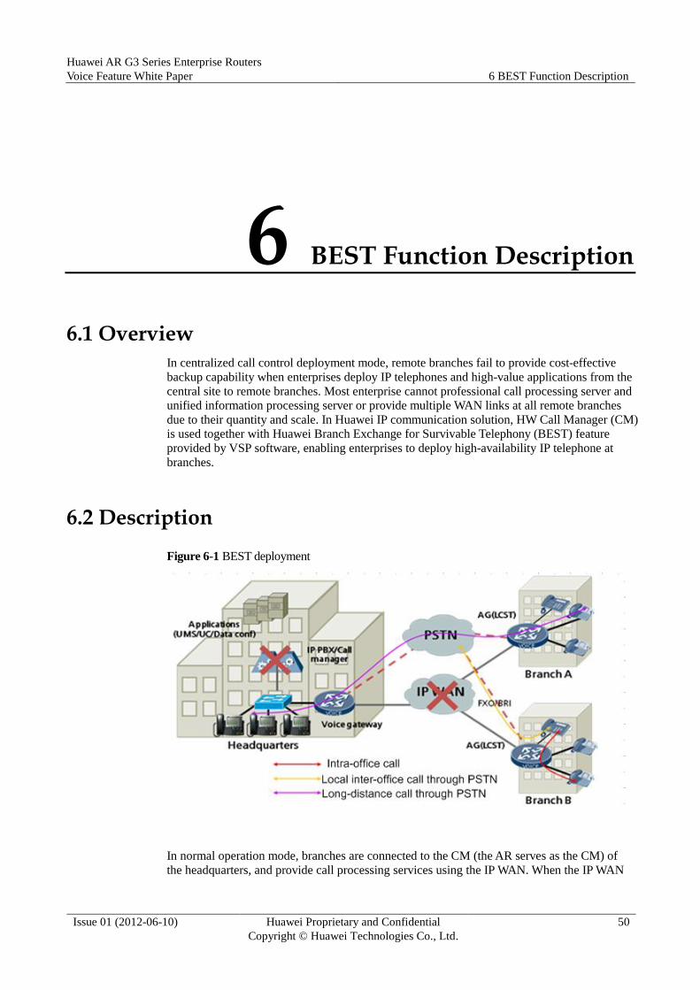
Huawei AR G3 Series Enterprise Routers
Voice Feature White Paper 6 BEST Function Description
Issue 01 (2012-06-10) Huawei Proprietary and Confidential
Copyright © Huawei Technologies Co., Ltd.
50
6 BEST Function Description
6.1 Overview
In centralized call control deployment mode, remote branches fail to provide cost-effective
backup capability when enterprises deploy IP telephones and high-value applications from the
central site to remote branches. Most enterprise cannot professional call processing server and
unified information processing server or provide multiple WAN links at all remote branches
due to their quantity and scale. In Huawei IP communication solution, HW Call Manager (CM)
is used together with Huawei Branch Exchange for Survivable Telephony (BEST) feature
provided by VSP software, enabling enterprises to deploy high-availability IP telephone at
branches.
6.2 Description
Figure 6-1 BEST deployment
In normal operation mode, branches are connected to the CM (the AR serves as the CM) of
the headquarters, and provide call processing services using the IP WAN. When the IP WAN

Huawei AR G3 Series Enterprise Routers
Voice Feature White Paper 6 BEST Function Description
Issue 01 (2012-06-10) Huawei Proprietary and Confidential
Copyright © Huawei Technologies Co., Ltd.
51
link of the CM is disconnected or both the active and standby CMs break down, the remote
BEST voice regeneration function of the local voice gateway on the branch must be enabled
to maintain local voice communication, including the registration and call management of
local POTS telephone and IP telephone. In addition, branches provide call route backup to the
PSTN using the backup AT0/BRI trunk. The BRI trunk is supported in AR V200R002C02.
When the IP WAN link resumes or the CMs recover, the VoIP services are automatically
switched back to the CM in the headquarters, and the POTS calls on the CMs in the
headquarters are resumed using the SIP AG.
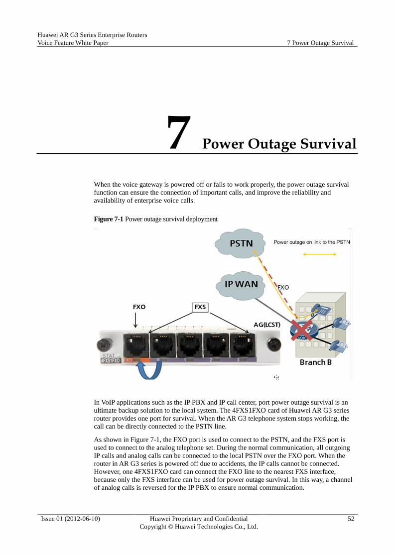
Huawei AR G3 Series Enterprise Routers
Voice Feature White Paper 7 Power Outage Survival
Issue 01 (2012-06-10) Huawei Proprietary and Confidential
Copyright © Huawei Technologies Co., Ltd.
52
7 Power Outage Survival
When the voice gateway is powered off or fails to work properly, the power outage survival
function can ensure the connection of important calls, and improve the reliability and
availability of enterprise voice calls.
Figure 7-1 Power outage survival deployment
In VoIP applications such as the IP PBX and IP call center, port power outage survival is an
ultimate backup solution to the local system. The 4FXS1FXO card of Huawei AR G3 series
router provides one port for survival. When the AR G3 telephone system stops working, the
call can be directly connected to the PSTN line.
As shown in Figure 7-1, the FXO port is used to connect to the PSTN, and the FXS port is
used to connect to the analog telephone set. During the normal communication, all outgoing
IP calls and analog calls can be connected to the local PSTN over the FXO port. When the
router in AR G3 series is powered off due to accidents, the IP calls cannot be connected.
However, one 4FXS1FXO card can connect the FXO line to the nearest FXS interface,
because only the FXS interface can be used for power outage survival. In this way, a channel
of analog calls is reversed for the IP PBX to ensure normal communication.

Huawei AR G3 Series Enterprise Routers
Voice Feature White Paper 8 Call Manager System
Issue 01 (2012-06-10) Huawei Proprietary and Confidential
Copyright © Huawei Technologies Co., Ltd.
53
8 Call Manager System
The CM system provides enhanced functions for AR G3 series routers, and the PBX or hybrid
PBX functions for enterprises. With the CM system, enterprises can deploy data connections
and call solution on their existing networks. The CM system provides advanced functions that
cannot be implemented in multiple call solutions. It combines IP call and data routing service
in a single solution, meeting customers' service requirements at lower O&M costs.
8.1 Advantages
The VoIP technology develops rapidly and its cost advantage has been recognized by
enterprises as it integrates the voice, video, and data services on a single network. Because the
CM system is integrated on a router, the system features the following specific advantages:
Single integrated voice and data platform providing cost-effective operation for all
enterprise branches: The AR G3 series routers provide functions such as the QoS,
network security, encryption, and firewall for enterprise offices. The routers provide
integrated functions, such as IP call, voice message, and automatic answer. One device
can meet all the service requirements, simplifying management, operation, and
maintenance, and reducing the total cost of ownership.
Unified key system and IP PBX function: Specific functions must be provided for
different enterprises. The CM system provides powerful value-added voice features to
improve the production efficiency of end users and enterprises.
Scalability: The AR G3 series routers provide the CM system with flexible interfaces
such as the PSTN interfaces and widely-used WAN interfaces. These interfaces improve
the flexibility of the CM system, and facilitate the integration of voice services and data
services.
Items supported by the CM system are as follows:
User management and call management of the POTS and ISDN telephones, and the SIP
UE
All PBX services
Various trunks such as the AT0, E1, and SIP

Huawei AR G3 Series Enterprise Routers
Voice Feature White Paper 8 Call Manager System
Issue 01 (2012-06-10) Huawei Proprietary and Confidential
Copyright © Huawei Technologies Co., Ltd.
54
8.2 Deployment
Figure 8-1 CM deployment
VOICE
VOICE
SIP AG
IP PBX
Call Manager
POTS user FAX PC userSIP user
VOICE
IP NetwortPSTN
POTS user
FAX
PC userSIP user
SIP AG
Headquarters
Branch
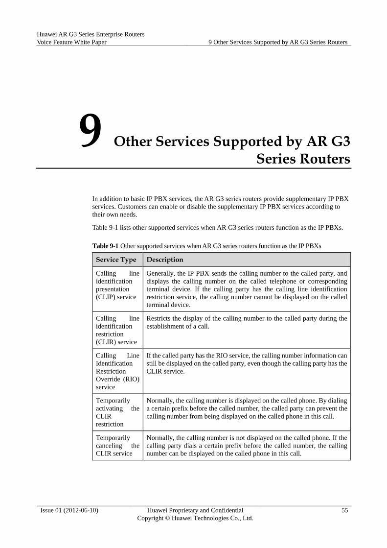
Huawei AR G3 Series Enterprise Routers
Voice Feature White Paper 9 Other Services Supported by AR G3 Series Routers
Issue 01 (2012-06-10) Huawei Proprietary and Confidential
Copyright © Huawei Technologies Co., Ltd.
55
9 Other Services Supported by AR G3 Series Routers
In addition to basic IP PBX services, the AR G3 series routers provide supplementary IP PBX
services. Customers can enable or disable the supplementary IP PBX services according to
their own needs.
Table 9-1 lists other supported services when AR G3 series routers function as the IP PBXs.
Table 9-1 Other supported services when AR G3 series routers function as the IP PBXs
Service Type Description
Calling line
identification
presentation
(CLIP) service
Generally, the IP PBX sends the calling number to the called party, and
displays the calling number on the called telephone or corresponding
terminal device. If the calling party has the calling line identification
restriction service, the calling number cannot be displayed on the called
terminal device.
Calling line
identification
restriction
(CLIR) service
Restricts the display of the calling number to the called party during the
establishment of a call.
Calling Line
Identification
Restriction
Override (RIO)
service
If the called party has the RIO service, the calling number information can
still be displayed on the called party, even though the calling party has the
CLIR service.
Temporarily
activating the
CLIR
restriction
Normally, the calling number is displayed on the called phone. By dialing
a certain prefix before the called number, the called party can prevent the
calling number from being displayed on the called phone in this call.
Temporarily
canceling the
CLIR service
Normally, the calling number is not displayed on the called phone. If the
calling party dials a certain prefix before the called number, the calling
number can be displayed on the called phone in this call.

Huawei AR G3 Series Enterprise Routers
Voice Feature White Paper 9 Other Services Supported by AR G3 Series Routers
Issue 01 (2012-06-10) Huawei Proprietary and Confidential
Copyright © Huawei Technologies Co., Ltd.
56
Service Type Description
Call hold During the conversation between user A (service user) and user B, user A
can press hookflash to suspend the call, and handle a temporary
emergency. In this case, user A can hear a special dial tone, and user B can
hear a hold tone (for example, a piece of music). User A can press
hookflash again to restore the call. The call hold service is the basis of
other hooking services.
Double
communication
(DC)
When the call between user A and user B enters the call hold status, user A
can place a call to user C, and switch between the two conversations.
Call waiting When user C places a call to user A who is in conversation, user A can
allow user C to wait. Meanwhile, the system displays a number or plays a
prompt tone to tell user A that a subscriber is waiting. User A can release
the ongoing call or hold the call and then connect to user C.
Call transfer
service
User B (transferor) who is in conversation with user A (transferee) can
transfer the call to user C (transfer target). User B releases the call, and the
call between user A and user B is set up. With the call transfer service, the
service user can transfer the ongoing call to a third-party user by
performing corresponding operating.
Three-party
service
After the call between user A (service user) and user B is set up, user A
places a call to user C, and then allows user B and user C to join the
conversation. Then, a three-party voice conversation is set up.
Call forwarding When a user is called, the call is forwarded to a preset party if the user
registers the call forwarding service and the call flow satisfies forwarding
conditions.
Call forwarding-unconditional (CFU): All calls of a service user are
forwarded to a preset party unconditionally. The AR supports remote
registration of the CFU service.
Call forwarding-busy (CFB): When a user places a call to a service
user who is in conversation, the call is forwarded to a preset party. The AR
supports remote registration of the CFB service.
Call forwarding-no reply (CFNR): When a call placed to a service user is
not answered, the call is forwarded to a preset party. The AR supports
remote registration of the CFNR service.
Call forwarding-offline (CFO): When the called user is offline, the
incoming call is forwarded to the preset party. (Offline: The IP PBX
changes the user status to the offline status if new subscription of the user
is not refreshed after subscription timeout.) The AR supports remote
registration of the CFO service.
Completion of
Calls to Busy
Subscriber
(CCBS)
The IP PBX monitors the called party status when the called party is busy.
When the called party is idle, the IP PBX notifies the calling party so that
the calling party can determine whether to make a call to the called party
again.
Completion of
Communicatio
n on no Reply
(CCNR)
When the called number is busy, the IP PBX monitors the called party
status. When the called party is idle, the IP PBX notifies the calling party,
and determines whether to make a call according to the status of the
calling and called parties.

Huawei AR G3 Series Enterprise Routers
Voice Feature White Paper 9 Other Services Supported by AR G3 Series Routers
Issue 01 (2012-06-10) Huawei Proprietary and Confidential
Copyright © Huawei Technologies Co., Ltd.
57
Service Type Description
Callback A service user can dial the number of the last incoming call using the
service code.
Missed call A service user can hear the voice prompt of the last missed call, and dial
the number of the last missed incoming call.
Redial A service user can redial the number of the last outgoing call.
Password call
service
A service user can use or limit the international toll of the telephone by
setting the password. The password call priority level is higher than other
call-out rights. Even if a user has no call-out right, the user can place a call
using the password call service.
Password call
barring
A service user can use or limit the inter-office calls of the telephone by
setting the password.
Number barring Call initiation is limited. When a user registering this service calls by
dialing the preset barred number, the call is barred.
Direct dialing
to access the
system
An external user can call an internal by dialing the PSTN long number of
the internal user. The call does not need to be transferred to this user using
the automatic switchboard.
Do-not-disturb A user who does not expect to be called can use this service. After the
do-not-disturb service is registered, all incoming calls to the user are
answered by the IP PBX. Outgoing calls of the user are not affected. The
special dial tone is played after the calling user picks up the phone.
Reject
anonymous call
The service allows a service user to reject an anonymous call (with no
calling number displayed) and allows the system to play an announcement
to the calling number after call rejection.
Selective call
acceptance
If an incoming call meets the requirements preset by the service user, the
call is connected. If not, the call is barred.
Selective call
rejection
If an incoming call meets the requirements preset by the service user, the
call is barred. If not, the call is connected.
Simultaneous
ringing
When a calling party dials the access number of a simultaneous ringing
group, all member phones in the group ring simultaneously, and the called
party can answer the call using any ringing phone.
Sequential
ringing
When a calling party dials the access number of a sequential ringing
group, member phones in the group ring in the configured sequence.
Co-group
pickup
Users A and B belong to the same pickup group. When user B's phone
rings, user A (service user) answers a call addressed to user B by dialing
the pickup access code.
Designated
pickup
When the phone of user A rings, user B in the same group can dial the
service access code plus user A's phone number to answer the call.
One number
link you
(ONLY)
Multiple terminals of the service user share one number, and the
sequential ringing and simultaneous ringing are supported.
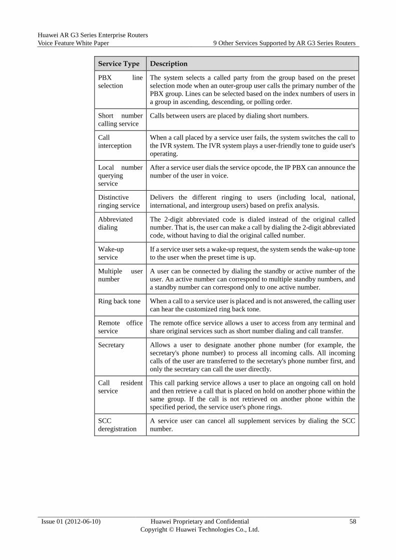
Huawei AR G3 Series Enterprise Routers
Voice Feature White Paper 9 Other Services Supported by AR G3 Series Routers
Issue 01 (2012-06-10) Huawei Proprietary and Confidential
Copyright © Huawei Technologies Co., Ltd.
58
Service Type Description
PBX line
selection
The system selects a called party from the group based on the preset
selection mode when an outer-group user calls the primary number of the
PBX group. Lines can be selected based on the index numbers of users in
a group in ascending, descending, or polling order.
Short number
calling service
Calls between users are placed by dialing short numbers.
Call
interception
When a call placed by a service user fails, the system switches the call to
the IVR system. The IVR system plays a user-friendly tone to guide user's
operating.
Local number
querying
service
After a service user dials the service opcode, the IP PBX can announce the
number of the user in voice.
Distinctive
ringing service
Delivers the different ringing to users (including local, national,
international, and intergroup users) based on prefix analysis.
Abbreviated
dialing
The 2-digit abbreviated code is dialed instead of the original called
number. That is, the user can make a call by dialing the 2-digit abbreviated
code, without having to dial the original called number.
Wake-up
service
If a service user sets a wake-up request, the system sends the wake-up tone
to the user when the preset time is up.
Multiple user
number
A user can be connected by dialing the standby or active number of the
user. An active number can correspond to multiple standby numbers, and
a standby number can correspond only to one active number.
Ring back tone When a call to a service user is placed and is not answered, the calling user
can hear the customized ring back tone.
Remote office
service
The remote office service allows a user to access from any terminal and
share original services such as short number dialing and call transfer.
Secretary Allows a user to designate another phone number (for example, the
secretary's phone number) to process all incoming calls. All incoming
calls of the user are transferred to the secretary's phone number first, and
only the secretary can call the user directly.
Call resident
service
This call parking service allows a user to place an ongoing call on hold
and then retrieve a call that is placed on hold on another phone within the
same group. If the call is not retrieved on another phone within the
specified period, the service user's phone rings.
SCC
deregistration
A service user can cancel all supplement services by dialing the SCC
number.
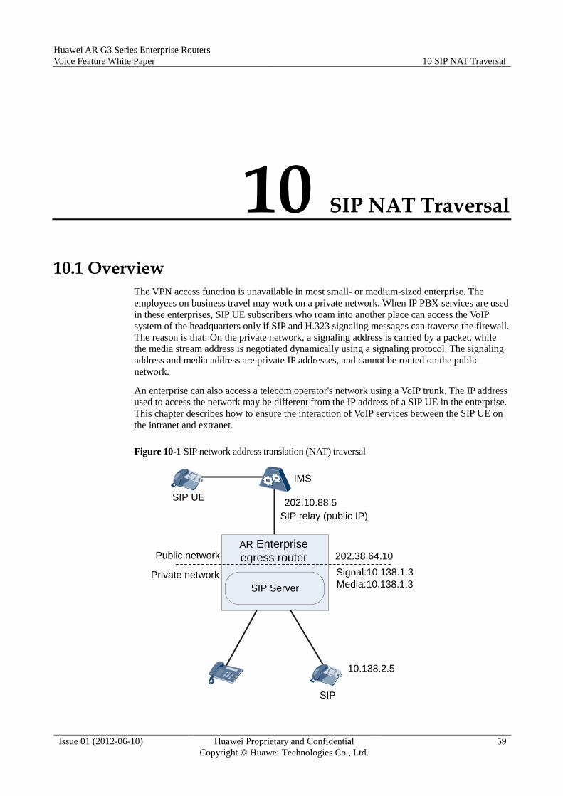
Huawei AR G3 Series Enterprise Routers
Voice Feature White Paper 10 SIP NAT Traversal
Issue 01 (2012-06-10) Huawei Proprietary and Confidential
Copyright © Huawei Technologies Co., Ltd.
59
10 SIP NAT Traversal
10.1 Overview
The VPN access function is unavailable in most small- or medium-sized enterprise. The
employees on business travel may work on a private network. When IP PBX services are used
in these enterprises, SIP UE subscribers who roam into another place can access the VoIP
system of the headquarters only if SIP and H.323 signaling messages can traverse the firewall.
The reason is that: On the private network, a signaling address is carried by a packet, while
the media stream address is negotiated dynamically using a signaling protocol. The signaling
address and media address are private IP addresses, and cannot be routed on the public
network.
An enterprise can also access a telecom operator's network using a VoIP trunk. The IP address
used to access the network may be different from the IP address of a SIP UE in the enterprise.
This chapter describes how to ensure the interaction of VoIP services between the SIP UE on
the intranet and extranet.
Figure 10-1 SIP network address translation (NAT) traversal
SIP Server
AR Enterprise
egress routerPublic network
Private network Signal:10.138.1.3
Media:10.138.1.3
202.38.64.10
SIP UE
IMS
SIP relay (public IP)
202.10.88.5
10.138.2.5
SIP

Huawei AR G3 Series Enterprise Routers
Voice Feature White Paper 10 SIP NAT Traversal
Issue 01 (2012-06-10) Huawei Proprietary and Confidential
Copyright © Huawei Technologies Co., Ltd.
60
10.2 SIP NAT Traversal Principles
The payload of a SIP message carries address information. For example, the Contract field
describes the signaling contact address, and the SDP field describes the media address.
However, the NAT function translates only the addresses in the UDP/TCP packet header and
IP packet header, and does not translate the address in payload. As a result, the IP addresses in
the IP packet header and UDP/TCP packet header are translated into public IP addresses, but
the IP address in payload is still a private IP address. Therefore, signaling and media
connections that require the address in the payload cannot be set up.
The following technologies can be used to implement NAT traversal for SIP signaling and
media streams:
1. NAT ALG: The NAT application level gateway (ALG) can identify application layer
protocols on the NAT device, and translate the addresses in protocol packets to a public
address. However, the deployment mode is difficult to implement because all NAT
devices must be upgraded, and these devices must be upgraded again when a new
application protocol is added. For SIP ALG call processes, see section 3.5 "VoIP (SIP)
MT Process" of RFC3665.
2. Middlebox communication (MIDCOM) for RFC3303: In the MIDCOM architecture,
Middlebox (NAT/FW) is controlled by using the trustable MIDCOM Agent. VoIP
protocols are identified by the MIDCOM Agent instead of the Middlebox. The
MIDCOM Agent is integrated on a call control server, such as SIP server. Therefore,
VoIP protocols are transparent to the Middlebox.
3. Proxy technologies: In the IMS solution, a session boarder controller (SBC) is used to
solve the SIP traversal problem in the following way: The SBC reassigns the address and
port for receiving signaling and RTP streams from the intranet or extranet. In this case,
the NAT between different network areas, such as between the public network and
private network, is implemented to support NAT traversal for signaling/media streams.
Signaling and media streams can be transmitted directionally by using proxy
technologies without special requirements for universal NAT networking devices.
Therefore, existing NAT devices do not need to be upgraded and telecom operators can
carry out services smoothly.
4. Tunnel mechanism: The tunnel-based traversal is to encapsulate data flows that need to
traverse the NAT device into tunnels so that the data flows do not need to be processed
by NAT device or firewall. Logically, the tunnel mechanism is composed of the tunnel
client and tunnel server. The tunnel client and tunnel server establish a tunnel using a
tunneling protocol, allowing signaling and media stream to transparently traverse the
NAT device. The tunnel client does not need to identify call signaling protocols, such as
H.323, SIP, MGCP or H.248. The tunnel server identifies signaling protocols and
forwards signaling messages to a server on the public network. Usually, the tunnel client
is on a private network, and the tunnel server is on a public network. With the tunnel
mechanism, NAT traversal can be implemented without upgrading existing NAT devices.
Only several known ports on the NAT devices need to be enabled by configuring
relevant policies. In addition, the tunnel traversal mechanism can easily implement
multi-level NAT traversal.
5. Simple traversal of UDP through NAT (STUN), first defined in RFC3489 and then
replaced by the RFC5389: The functions on the STUN client are integrated into the SIP
entities on a private network. Before a call is originated to the extranet, a SIP entity
sends a STUN to the STUN server to obtain the external addresses configured on the
NAT device, including signaling and media addresses. In subsequent SIP call signaling,
the SIP entity fills in the external addresses in the local address field. STUN is not
applicable to symmetric NAT and TCP NAT traversal. In addition, because RTP and
RTCP use the external ports obtained from the NAT device, the rule (RTCP port = RTP

Huawei AR G3 Series Enterprise Routers
Voice Feature White Paper 10 SIP NAT Traversal
Issue 01 (2012-06-10) Huawei Proprietary and Confidential
Copyright © Huawei Technologies Co., Ltd.
61
port + 1) is disobeyed. As a result, the end-to-end RTCP packet transmission fails. To
solve this problem, use a=rtcp or a=rtcp-mux in the SDP describe RTCP ports. For
details, see RFC3605 or RFC5761.
6. Traversal using relay NAT (TURN) defined in RFC5766: The mode is similar to STUN.
The functions on the TURN client are integrated into the SIP entities on a private
network. Before initiating communication with an extranet, an SIP entity requests an
address and a port from the TURN server. Subsequent signaling and media packets are
forwarded using the TURN server in relay mode. The TURN mode is applicable to
symmetric NAT and TCP NAT traversal. The TURN server ensure that RTCP port =
RTP port + 1.
7. Interactive connectivity establishment (ICE) defined in RFC5245: It is not a new
protocol, but combines the STUN, TURN, and RSIP. ICE uses these protocols in
suitable cases to overcome shortcomings brought by only one protocol.
8. Adding response-port (rport) in the Via header field: The request receiver uses the
response-port (rport) parameter to record the source port when receiving a request
message, and uses the received parameter to record the source IP address. The receiver
uses the received&rport parameter to send subsequent response messages, ensuring
NAT traversal of response messages. For details, see RFC3581. The method can be used
to only implement traversal of SIP signaling response messages.
10.3 AR SIP NAT Traversal Solution (SBC Solution) Signaling proxy
The AR can serve as the IP PBX and process all registration and call messages of users.
When receiving signaling messages from external users, the AR processes signaling
messages and forwards them to the IMS (SBC). The AR is a user for the IMS (SBC). The
IMS sends a call request to the AR. The AR processes the request, and then forwards it to
the real called party.
Media proxy
All media streams that are exchanged between users in on the internal network and
external networks are processed and forwarded using the RTP/RTCP over the AR. The
AR checks packet validity, and determines media stream forwarding policies including
packet filter policy, QoS policy, and address translation policy based on the signaling
process results. Then the AR specifies the address and port for receiving RTP streams of
intranet and extranet users. In this way, media streams are forwarded properly and
guaranteed good QoS and security in any networking.

Huawei AR G3 Series Enterprise Routers
Voice Feature White Paper 10 SIP NAT Traversal
Issue 01 (2012-06-10) Huawei Proprietary and Confidential
Copyright © Huawei Technologies Co., Ltd.
62
Figure 10-2 Processes in the SBC solution
CPE SBC
192.168.0.1 192.168.0.2 65.65.65.1 65.65.65.98
Media Proxy functon
enabled(SBC embeded)
192.168.0.1:10248
65.65.65.1:61448
INVITE
Destination Addr:65.65.65.1 5060
SDP:65.65.65.98 42812
INVITE
Destination Addr:192.168.0.1 5060
SDP:192.168.0.2 61440
200 OK
Source Addr:192.168.0.1 5060
SDP:192.168.0.1 10248
200 OK
Source Addr:65.65.65.1 5060
SDP:65.65.65.1 61448
RTP
Source Addr:192.168.0.1 10248
Destination Addr:192.168.0.2 61440
RTP
Source Addr:65.65.65.1 61448
Destination Addr:65.65.65.98 42812
RTP
Source Addr:65.65.65.98 42812
Destin Addr:65.65.65.1 61448
RTP
Source Addr:192.168.0.2 61440
Destin Addr:192.168.0.1 10248
65.65.65.98:42812
192.168.0.2:61440
1. The SBC sends an Invite message to the CPE. Assume that SDP carries the local media
address 65.65.65.98, and the UDP port number is 42812. After receiving the SIP
message, the SIP server/proxy on the CPE changes the SDP media address to a private
network address 192.168.0.2, and changes the UDP port number to 61440. The SIP
server/proxy then sends the Invite message to a SIP phone and records proxy mapping
entries.
2. The SIP phone receives the Invite message, records the media address and port number
192.168.0.2:61440 of the peer end, and responds with a 200 OK message. In this case,
the SDP carries the local media address 192.168.0.1, and the UDP port number is
changed to 10248.
3. The CPE receives the 200 OK message from the SIP phone, changes the media address
to the public network address 65.65.65.1, and changes the UDP port number to 61448. In
addition, the CPE records the mapping the original media address and the new media
address.
4. The message is sent from the SIP phone to the destination media address
192.168.0.2:61440. The CPE changes the destination media address to 65.65.65.98
42812 and sends the message to the SBC.
5. The SBC sends the message to the destination media address 65.65.65.1:61448. The CPE
changes the phone destination media address to 192.168.0.1:10248 and sends the
message to the SIP phone.
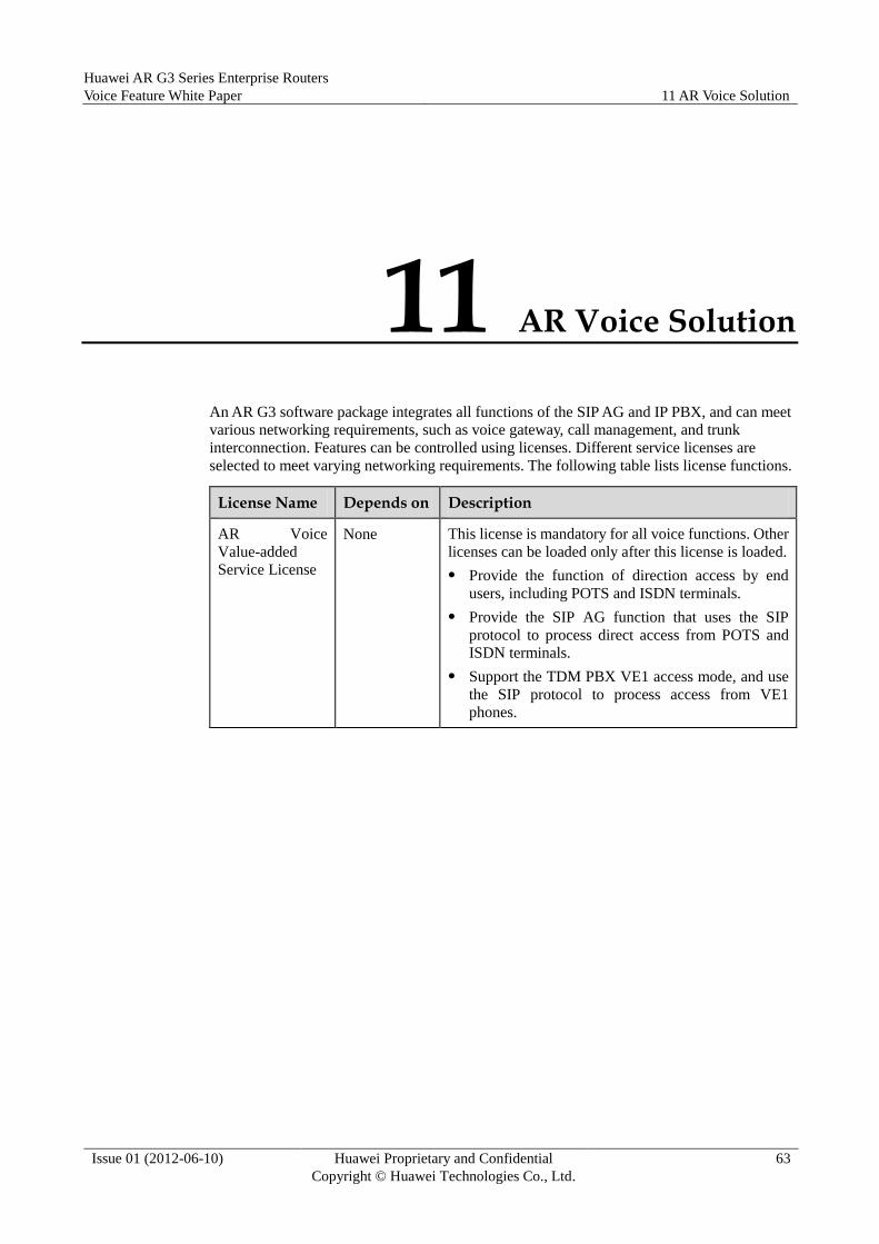
Huawei AR G3 Series Enterprise Routers
Voice Feature White Paper 11 AR Voice Solution
Issue 01 (2012-06-10) Huawei Proprietary and Confidential
Copyright © Huawei Technologies Co., Ltd.
63
11 AR Voice Solution
An AR G3 software package integrates all functions of the SIP AG and IP PBX, and can meet
various networking requirements, such as voice gateway, call management, and trunk
interconnection. Features can be controlled using licenses. Different service licenses are
selected to meet varying networking requirements. The following table lists license functions.
License Name Depends on Description
AR Voice
Value-added
Service License
None This license is mandatory for all voice functions. Other
licenses can be loaded only after this license is loaded.
Provide the function of direction access by end
users, including POTS and ISDN terminals.
Provide the SIP AG function that uses the SIP
protocol to process direct access from POTS and
ISDN terminals.
Support the TDM PBX VE1 access mode, and use
the SIP protocol to process access from VE1
phones.
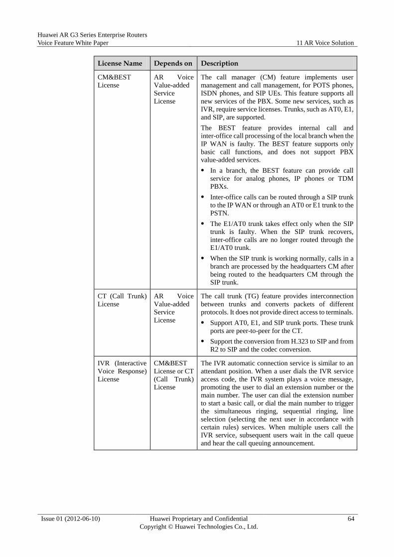
Huawei AR G3 Series Enterprise Routers
Voice Feature White Paper 11 AR Voice Solution
Issue 01 (2012-06-10) Huawei Proprietary and Confidential
Copyright © Huawei Technologies Co., Ltd.
64
License Name Depends on Description
CM&BEST
License
AR Voice
Value-added
Service
License
The call manager (CM) feature implements user
management and call management, for POTS phones,
ISDN phones, and SIP UEs. This feature supports all
new services of the PBX. Some new services, such as
IVR, require service licenses. Trunks, such as AT0, E1,
and SIP, are supported.
The BEST feature provides internal call and
inter-office call processing of the local branch when the
IP WAN is faulty. The BEST feature supports only
basic call functions, and does not support PBX
value-added services.
In a branch, the BEST feature can provide call
service for analog phones, IP phones or TDM
PBXs.
Inter-office calls can be routed through a SIP trunk
to the IP WAN or through an AT0 or E1 trunk to the
PSTN.
The E1/AT0 trunk takes effect only when the SIP
trunk is faulty. When the SIP trunk recovers,
inter-office calls are no longer routed through the
E1/AT0 trunk.
When the SIP trunk is working normally, calls in a
branch are processed by the headquarters CM after
being routed to the headquarters CM through the
SIP trunk.
CT (Call Trunk)
License
AR Voice
Value-added
Service
License
The call trunk (TG) feature provides interconnection
between trunks and converts packets of different
protocols. It does not provide direct access to terminals.
Support AT0, E1, and SIP trunk ports. These trunk
ports are peer-to-peer for the CT.
Support the conversion from H.323 to SIP and from
R2 to SIP and the codec conversion.
IVR (Interactive
Voice Response)
License
CM&BEST
License or CT
(Call Trunk)
License
The IVR automatic connection service is similar to an
attendant position. When a user dials the IVR service
access code, the IVR system plays a voice message,
promoting the user to dial an extension number or the
main number. The user can dial the extension number
to start a basic call, or dial the main number to trigger
the simultaneous ringing, sequential ringing, line
selection (selecting the next user in accordance with
certain rules) services. When multiple users call the
IVR service, subsequent users wait in the call queue
and hear the call queuing announcement.

Huawei AR G3 Series Enterprise Routers
Voice Feature White Paper 11 AR Voice Solution
Issue 01 (2012-06-10) Huawei Proprietary and Confidential
Copyright © Huawei Technologies Co., Ltd.
65
11.1 AR Inter-Branch Voice Communication Solution
Huawei's voice communications system has three deployment models: centralized call control
model, distributed call control model, and mixed call control model.
Select the deployment model according to the enterprise scale, branch distribution, and
expansion plan based on the following factors:
1. Locations of the headquarters and branches. If the headquarters and branches are in the
same administrative region (they have the same PSTN area code), the centralized call
control model is recommended. In the model, all voice users in the enterprise
register with the headquarters, implement voice interconnection over the headquarters,
and initiate inter-office calls over the headquarters. If the headquarters and branches are
located in different PSTN areas, branches are connected to the headquarters through the
enterprise's intranet. The distributed call control model is recommended. In this model,
each branch processes internal calls and local inter-office calls.
2. Staff distribution and traffic volume between the headquarters and branches. If each
branch has a few employees and low voice traffic volume, it is recommended that the
centralized call control model be used to reduce workload on data configuration and
network maintenance in branches. If the number of employees in branches approximates
to that in the headquarters, it is recommended that the distributed call control model be
used to reduce bandwidth consumption between the headquarters and branches.
3. Voice service deployment. If value-added voice services are controlled by the
headquarters, the centralized call control model is recommended so that fewer devices
need to be deployed in branches. If branches need to control value-added voice services,
the distributed call control model is recommended.
4. Bandwidth and QoS guarantee. If links between the headquarters and branches can
provide sufficient bandwidth and QoS guarantee for voice services, the centralized call
control model is recommended. If links between the headquarters and branches cannot
provide sufficient bandwidth or QoS guarantee, the distributed call control model is
recommended because it reduces bandwidth consumption between the headquarters and
branches.
The call control models are described in the following sections.
11.1.1 Centralized Call Control Model
If the headquarters and branches of an enterprise are in the same area, the headquarters
connects to branches over a metropolitan area network (MAN). The CM and CT features are
deployed in the headquarters, and the AG feature is deployed in the branches. That is, the AR
router in the headquarters is used as an IP PBX, and the AR routers in the branches as SIP
AGs.
All voice users in the headquarters and branches register with the AR in the headquarters. The
AR in the headquarters provides call control services (CM) for all users, and connects
enterprise users to the local telecom operators (CT). Egress routers of medium-sized branches
provide the survivable remote site telephony (SRST) and power outage survival functions to
enhance communication reliability.

Huawei AR G3 Series Enterprise Routers
Voice Feature White Paper 11 AR Voice Solution
Issue 01 (2012-06-10) Huawei Proprietary and Confidential
Copyright © Huawei Technologies Co., Ltd.
66
Figure 11-1 Centralized call control deployment
The AR on the headquarters is used as the VoIP CM in the enterprise. All internal short
numbers and users are registered and managed in the AR. In the headquarters deployed with
narrowband voice services, the existing TDM PBXs can still be used to provide call services
for analog users, and connect to the AR through E1/FXO ports. In this case, the AR router
needs to load the CT license to implement trunk interconnection.
The AR in a branch is used as a voice gateway to provide the AG function, and implement the
conversion from analog signaling to SIP signaling. For a branch with high reliability
requirement, the BEST feature can be loaded to provide basic call services for local
phones when the IP MAN is faulty.
The IP PBX in the headquarters is configured as follows:
interface Ethernet2/0/0 //Configure an IP address for an IP PBX upstream port.
ip address 192.168.1.1 255.255.255.0
#
voice
voip-address signalling interface Ethernet2/0/0 192.168.1.1 //Configure the
signaling address pool.
voip-address media interface Ethernet2/0/0 192.168.1.1 //Configure the media
address pool.
#
enterprise hw //Create the enterprise hw
dn-set local //Create the local DN set.
#
sipserver //Configure a SIP server.
Huawei AR G3 Series Enterprise Routers
Voice Feature White Paper 11 AR Voice Solution
Issue 01 (2012-06-10) Huawei Proprietary and Confidential
Copyright © Huawei Technologies Co., Ltd.
67
signalling-address ip 192.168.1.1 port 5060 //Set the SIP server signaling address
to 192.168.1.1, and set the signaling port number to 5060
media-ip 192.168.1.1 //Set the SIP server media address to 192.168.1.1
register-uri huawei.com //Set the SIP server URI to huawei.com
home-domain huawei.com //Set the home domain URI of the SIP server to huawei.com
#
callprefix 2 //Create call prefix 2.
prefix 2
enterprise hw dn-set local //Bind the enterprise hw and DN set local to the call
prefix.
call-type category basic-service attribute 0 //Set the call attribute to local
call.
digit-length 4 4 //Set the maximum number length to 4, and the minimum number length
to 4.
#
callprefix 3
prefix 3
enterprise hw dn-set local
call-type category basic-service attribute 0
digit-length 4 4
#
pbxuser 2222 sipue enterprise hw //Configure a PBX user 2222, and set its user type
to SIPUE and enterprise to hw.
sipue 2222 //Configure the SIPUE ID.
telno country-code 86 area-code 25 2222 //Configure a phone number for the PBX
user.
dn-set local //Specify the DN set for the PBX user.
call-right in international-toll out international-toll //Configure the call-in
and call-out rights for the PBX user.
#
pbxuser 2223 sipue enterprise hw
sipue 2223
telno country-code 86 area-code 25 2223
dn-set local
call-right in international-toll out international-toll
#
pbxuser 3000 pots enterprise hw //Configure a PBX user 3000, and set its type to
SIPUE and enterprise to hw.
port 1/0/0 //Specify the physical port to which the PBX user is bound.
telno country-code 86 area-code 25 3000
dn-set local
call-right in international-toll out international-toll
#
pbxuser 3001 pots enterprise hw
port 1/0/1
telno country-code 86 area-code 25 3001
dn-set local
call-right in international-toll out international-toll
#
pbxuser 3002 sipue enterprise hw
sipue 3002
telno country-code 86 area-code 25 3002
dn-set local
call-right in international-toll out international-toll
#

Huawei AR G3 Series Enterprise Routers
Voice Feature White Paper 11 AR Voice Solution
Issue 01 (2012-06-10) Huawei Proprietary and Confidential
Copyright © Huawei Technologies Co., Ltd.
68
return
The SIP AG in a branch is configured as follows:
interface Ethernet2/0/0 //Set the IP address for a SIP AG upstream port.
ip address 192.168.1.2 255.255.255.0
#
voice
voip-address signalling interface Ethernet 2/0/0 192.168.1.2
voip-address media interface Ethernet 2/0/0 192.168.1.2
#
sipag 1 //Create the SIP AG interface 1.
signalling-addr 192.168.1.2 5060 //Set the signaling IP address of the SIP AG
interface to 192.168.1.2, and set the signaling port number to 5060.
media-addr 192.168.1.2 //Set the media IP address of the SIP AG interface to
192.168.1.2.
primary-proxy-addr static 192.168.1.1 5060 //Set the address of the active proxy
server to 192.168.1.1, and set the signaling port number to 5060.
home-domain huawei.com //Set the home domain name to huawei.com.
#
sipaguser 1 port 1/0/0 //Create a SIP AG user and set its interface number.
base-telno 2222 //Configure the telephone number of the SIP AG user.
agid 1 //Set the SIP AG interface associated with the SIP AG user to 1.
#
sipaguser 2 port 1/0/1
base-telno 2223
agid 1
#
return
11.1.2 Distributed Call Control Model
If the headquarters and branches of an enterprise are in different areas and the branches
connect to the headquarters over a private IP network, the distributed call control model can
be used for the enterprise. The CM and CT features are deployed on ARs in the headquarters,
and the CM feature is deployed on ARs in the branches.
Voices users in the headquarters are registered on the AR (CM) in the headquarters, and voice
users in each branch are registered on the AR (CM) in the branch. Voice traffic is transmitted
between the headquarters and branches through voice routes. The AR of the headquarters
provides voice routes (CT) so that users in different branches can call each other.

Huawei AR G3 Series Enterprise Routers
Voice Feature White Paper 11 AR Voice Solution
Issue 01 (2012-06-10) Huawei Proprietary and Confidential
Copyright © Huawei Technologies Co., Ltd.
69
Figure 11-2 Distributed call control deployment
The IP PBX in the headquarters is configured as follows:
interface Serial2/0/0
link-protocol ppp
ip address 192.168.1.1 255.255.255.0
#
voice
voip-address signalling interface Serial 2/0/0 192.168.1.1
voip-address media interface Serial 2/0/0 192.168.1.1
pbx default-country-code 86
pbx default-area-code 25
#
enterprise hw
dn-set local
#
sipserver
signalling-address ip 192.168.1.1 port 5060
media-ip 192.168.1.1
register-uri huawei.com
home-domain huawei.com
#
trunk-group at0 fxo //Configure an AT0 trunk group.
enterprise hw dn-set local
call-right in international-toll //Configure the call-in right for the trunk group.

Huawei AR G3 Series Enterprise Routers
Voice Feature White Paper 11 AR Voice Solution
Issue 01 (2012-06-10) Huawei Proprietary and Confidential
Copyright © Huawei Technologies Co., Ltd.
70
call-right out international-toll //Configure the call-out right for the trunk
group.
trunk-at0 1/0/4 default-called-telno 22223000 reversepole-detect disable //Add
a trunk to the trunk group.
#
trunk-group sipip sip no-register //Configure a SIP trunk group.
enterprise hw dn-set local
call-right in international-toll
call-right out international-toll
signalling-address ip 192.168.1.1 port 5070 //Set a signaling address and signaling
port number.
media-ip 192.168.1.1 //Set a media address.
home-domain huawei.com //Set the home domain name of the trunk group to huawei.com.
register-uri huawei.com //Set the register URL of the trunk group to huawei.com.
peer-address static 192.168.2.1 5070 //Set the remote IP address of the trunk
group to 192.168.2.1, and set the port number to 5070.
#
callprefix 9
prefix 9
enterprise hw dn-set local
call-type category basic-service attribute 0
digit-length 1 15
destination-location inter-office
callroute trunkgroup1 at0
#
callprefix 2222
prefix 2222
enterprise hw dn-set local
call-type category basic-service attribute 0
digit-length 8 8
#
callprefix 20000
prefix 20000
enterprise hw dn-set local
call-type category basic-service attribute 0
digit-length 5 20
destination-location inter-office
callroute trunkgroup1 sipip //Configure a call route.
#
pbxuser 22223000 pots enterprise hw
port 1/0/0
telno country-code 86 area-code 25 22223000
dn-set local
call-right in international-toll out international-toll
service-right call-transfer enable
#
pbxuser 22223001 pots enterprise hw
port 1/0/1
telno country-code 86 area-code 25 22223001
dn-set local
call-right in international-toll out international-toll
#
afterroute-change 9 //Configure post-routing number change.
callprefix 9
trunk-group at0 //Bind the AT0 trunk group to the call route.

Huawei AR G3 Series Enterprise Routers
Voice Feature White Paper 11 AR Voice Solution
Issue 01 (2012-06-10) Huawei Proprietary and Confidential
Copyright © Huawei Technologies Co., Ltd.
71
calling party no-change //Set the calling number change rule: not to change the
calling number.
called del 7 1 //Configure the called number change rule: to delete the seventh
digit from the called number.
#
afterroute-change 20000
callprefix 20000
trunk-group sipip
calling party no-change
called del 7 5
#
Return
For IP PBX configurations in a branch, refer to the IP PBX configurations in the
headquarters.
11.1.3 Hybrid Call Control Model
An enterprise may have many branches. Some branches are in the same area and
communicate through an IP MAN; some branches are in different areas and communicate
through an IP leased line. The hybrid call control model is recommended for this enterprise. If
the enterprise has multiple branches in the same area, the enterprise can deploy the CM
feature in a large branch and deploy egress routers in other branches as AGs. Voice users in
this area are registered on the AR (CM) of the large branch. The egress routers of branches in
other areas load the CM feature. Voice users in these branches are registered on the ARs in
respective branches.
In the hybrid call control model, the communication mechanism used between branches in the
same area is the same as that used in the centralized call control model, and the
communication mechanism used between branches in different areas is the same as that used
in the distributed call control model.
11.2 AR Connecting to an IMS/NGN Network as AG
11.2.1 Market Positioning and Intended Customers
AR series routers are the mid-range-and-low-end enterprise routers that provide VoIP services.
Integrative VoIP module is an important feature of AR series routers. This solution aims at
enterprise users. Due to the performance limits, this solution is targeted at the resale VoIP
market.
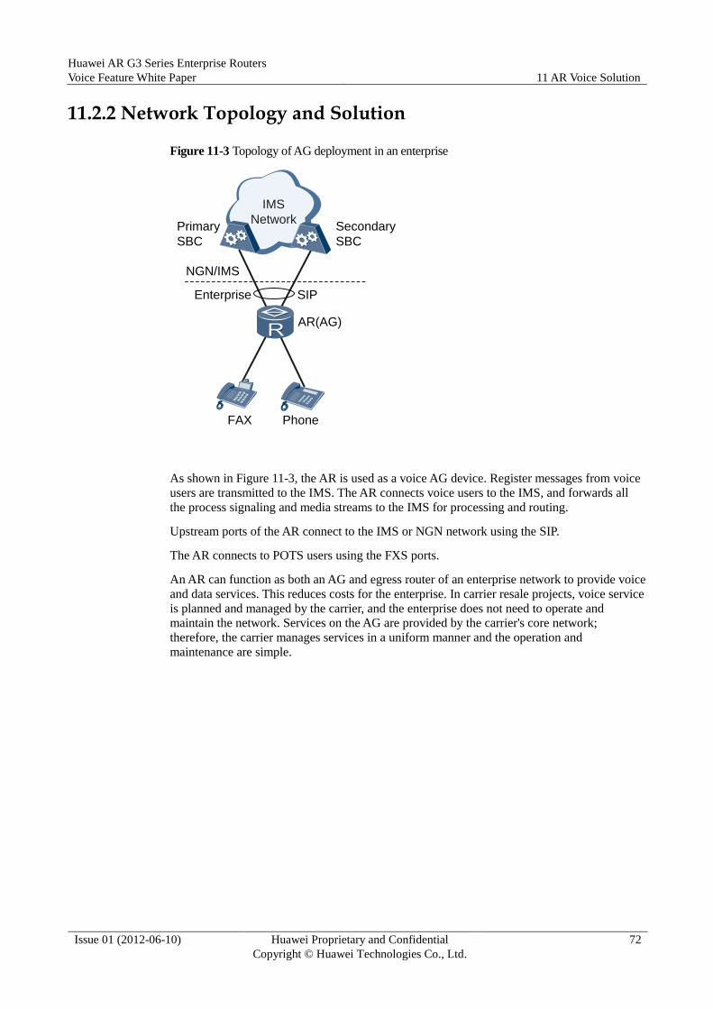
Huawei AR G3 Series Enterprise Routers
Voice Feature White Paper 11 AR Voice Solution
Issue 01 (2012-06-10) Huawei Proprietary and Confidential
Copyright © Huawei Technologies Co., Ltd.
72
11.2.2 Network Topology and Solution
Figure 11-3 Topology of AG deployment in an enterprise
IMS
Network
FAX Phone
Enterprise
NGN/IMS
Primary
SBC
Secondary
SBC
SIP
AR(AG)
As shown in Figure 11-3, the AR is used as a voice AG device. Register messages from voice
users are transmitted to the IMS. The AR connects voice users to the IMS, and forwards all
the process signaling and media streams to the IMS for processing and routing.
Upstream ports of the AR connect to the IMS or NGN network using the SIP.
The AR connects to POTS users using the FXS ports.
An AR can function as both an AG and egress router of an enterprise network to provide voice
and data services. This reduces costs for the enterprise. In carrier resale projects, voice service
is planned and managed by the carrier, and the enterprise does not need to operate and
maintain the network. Services on the AG are provided by the carrier's core network;
therefore, the carrier manages services in a uniform manner and the operation and
maintenance are simple.


