29
HUAWEI Huawei GTM900 GSM/GPRS Wireless Module Product Description V100R001 Huawei Technologies Proprietary
HUAWEI
Huawei GTM900 GSM/GPRS Wireless Module Product Description
V100R001
Huawei Technologies Proprietary

Huawei GTM900 GSM/GPRS Wireless Module
Product Description
Manual Version T2-032598-20050320-C-1.10
Product Version V100R001
BOM 31250298
Huawei Technologies Co., Ltd. provides customers with comprehensive technical support and service. Please feel free to contact our local office or company headquarters.
Huawei Technologies Co., Ltd.
Address: Huawei Industrial Base, Bantian, Longgang, Shenzhen 518129, P.R.China
Tel: +86-755-28780808
Global Hotline: +86-755-28560808
Website: www.huawei.com
E-mail:[email protected]
Huawei Technologies Proprietary

Copyright © 2005 Huawei Technologies Co., Ltd.
All Rights Reserved
No part of this manual may be reproduced or transmitted in any form or by any means without prior written consent of Huawei Technologies Co., Ltd.
Trademarks
, HUAWEI, C&C08, EAST8000, HONET, , ViewPoint, INtess, ETS, DMC,
TELLIN, InfoLink, Netkey, Quidway, SYNLOCK, Radium, M900/M1800, TELESIGHT, Quidview, Musa, Airbridge, Tellwin, Inmedia, VRP, DOPRA, iTELLIN, HUAWEI OptiX, C&C08 iNET, NETENGINE, OptiX, iSite, U-SYS, iMUSE, OpenEye, Lansway, SmartAX, infoX, TopEng are trademarks of Huawei Technologies Co., Ltd.
All other trademarks mentioned in this manual are the property of their respective holders.
Notice
The information in this manual is subject to change without notice. Every effort has been made in the preparation of this manual to ensure accuracy of the contents, but all statements, information, and recommendations in this manual do not constitute the warranty of any kind, express or implied.
Huawei Technologies Proprietary

Summary of Updates
This section provides the update history of this manual and introduces the contents of subsequent updates.
Update History
This manual is updated for a major product version to maintain consistency with system hardware or software versions and to incorporate customer suggestions.
Manual Version Notes
T2-032598-20050320-C-1.10 Initial field trial release
Relevant Documents
The manuals related to Huawei GTM900 GSM/GPRS Wireless Module are introduced in the table below:
Manual name Description
Huawei GTM900 GSM/GPRS Wireless Module Product Description
Introduces Huawei GTM900 GSM/GPRS Wireless Module in terms of specifications and interface signals
Huawei GTM900 GSM/GPRS Wireless Module AT Command Set
Describes the AT commands related to Huawei GTM900 GSM/GPRS Wireless Module
Updates of Contents
None
Huawei Technologies Proprietary
About This Manual
Release Notes
The product version that corresponds to the manual is GTM900 V100R001.
Organization
The manual consists of six chapters.
Chapter 1 Overview of GTM900 presents physical specifications, functional architecture and application of GTM900.
Chapter 2 Interface Signals describes the interface signals of GTM900.
Chapter 3 Electrical Characteristics of Interfaces presents the electrical characteristics of the interfaces, including absolute maximum ratings, recommended operating conditions and power supply characteristics.
Chapter 4 Interface Application presents the application of the interfaces, including UART interface, SIM interface, audio interface, ringer interface and power supply interface.
Chapter 5 Operating Process presents the operating process of GTM900, including powering on/off, software upgrade and data services.
Chapter 6 Acronyms and Abbreviations
Intended Audience
The manual is intended for the following readers:
Anyone who are interested in Huawei GTM900 GSM/GPRS Wireless Module, regarding its features, applications, structure and specifications.
Conventions
The manual uses the following conventions:
Huawei Technologies Proprietary
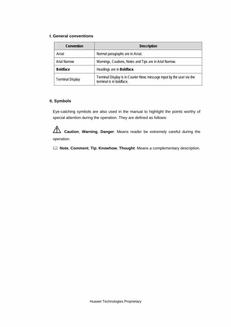
I. General conventions
Convention Description
Arial Normal paragraphs are in Arial.
Arial Narrow Warnings, Cautions, Notes and Tips are in Arial Narrow.
Boldface Headings are in Boldface.
Terminal Display Terminal Display is in Courier New; message input by the user via the terminal is in boldface.
II. Symbols
Eye-catching symbols are also used in the manual to highlight the points worthy of special attention during the operation. They are defined as follows:
Caution, Warning, Danger: Means reader be extremely careful during the
operation.
Note, Comment, Tip, Knowhow, Thought: Means a complementary description.
Huawei Technologies Proprietary
Product Description Huawei GTM900 GSM/GPRS Wireless Module Table of Contents
Huawei Technologies Proprietary
Table of Contents
Chapter 1 Overview of GTM900 ................................................................................................... 1-1 1.1 About This Chapter ............................................................................................................ 1-1 1.2 Intended Use of GTM900 .................................................................................................. 1-1 1.3 Physical specifications of GTM900.................................................................................... 1-1 1.4 Functions and Services Supported by GTM900................................................................ 1-2
1.4.1 Functional Characteristics of GTM900.................................................................... 1-2 1.4.2 Services Supported by GTM900............................................................................. 1-2
1.5 Functional Architecture of GTM900................................................................................... 1-3 1.6 Application of GTM900 ...................................................................................................... 1-3
1.6.1 Application to Terminal-Type Fixed Stations .......................................................... 1-3 1.6.2 Application to Phone-Type Fixed Stations .............................................................. 1-4 1.6.3 Application to Vehicle-Mounted Stations and Public Telephones........................... 1-5
Chapter 2 Interface Signals .......................................................................................................... 2-1 2.1 About This Chapter ............................................................................................................ 2-1 2.2 Interfaces of Signal Connector on GTM900 ...................................................................... 2-1
2.2.1 Interface Signals...................................................................................................... 2-1 2.2.2 Design of Signal Connector .................................................................................... 2-3
2.3 Antenna Interface............................................................................................................... 2-3
Chapter 3 Electrical Characteristics of Interfaces ..................................................................... 3-1 3.1 About This Chapter ............................................................................................................ 3-1 3.2 Absolute Maximum Ratings ............................................................................................... 3-1 3.3 Recommended Operating Conditions ............................................................................... 3-1 3.4 Power Supply Characteristics............................................................................................ 3-2
3.4.1 Input Power ............................................................................................................. 3-2 3.4.2 Operating Current.................................................................................................... 3-2
Chapter 4 Interface Application ................................................................................................... 4-1 4.1 About This Chapter ............................................................................................................ 4-1 4.2 UART Interface .................................................................................................................. 4-1 4.3 SIM Interface...................................................................................................................... 4-2 4.4 Audio Interface.................................................................................................................. 4-2 4.5 Ringer Interface................................................................................................................. 4-4 4.6 Power Supply Interface...................................................................................................... 4-5
Chapter 5 Operating Process....................................................................................................... 5-1 5.1 About This Chapter ............................................................................................................ 5-1 5.2 Powering on/off GTM900................................................................................................... 5-1
5.2.1 Powering UP GTM900 ............................................................................................ 5-1
i
Product Description Huawei GTM900 GSM/GPRS Wireless Module Table of Contents
Huawei Technologies Proprietary
5.2.2 Powering Down GTM900 ........................................................................................ 5-1 5.3 Software Upgrade of GTM900........................................................................................... 5-2 5.4 Data Services of GTM900 ................................................................................................. 5-2 5.5 Services Presentation Diagram of GTM900 ...................................................................... 5-2
Chapter 6 Acronyms and Abbreviations..................................................................................... 6-1
ii
Product Description Huawei GTM900 GSM/GPRS Wireless Module Chapter 1 Overview of GTM900
Huawei Technologies Proprietary
Chapter 1 Overview of GTM900
1.1 About This Chapter
This chapter presents the GTM900 GSM/GPRS wireless module from the following aspects:
Intended Use of GTM900 Physical specifications of GTM900 Functions and Services Supported by GTM900 Functional Architecture of GTM900 Application of GTM900
1.2 Intended Use of GTM900
Huawei GTM900 is a type of tri-band wireless module supporting both GSM and GPRS. The module supports both standard AT commands and enhanced AT commands, and provides a variety of voice services and data services. It is an ideal solution to high-speed data transmission.
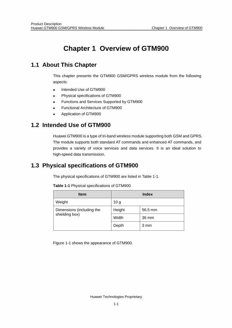
1.3 Physical specifications of GTM900
The physical specifications of GTM900 are listed in Table 1-1.
Table 1-1 Physical specifications of GTM900
Item Index
Weight 10 g
Height 56.5 mm
Width 36 mm
Dimensions (including the shielding box)
Depth 3 mm
Figure 1-1 shows the appearance of GTM900.
1-1

Product Description Huawei GTM900 GSM/GPRS Wireless Module Chapter 1 Overview of GTM900
Huawei Technologies Proprietary
Figure 1-1 Appearance of GTM900
1.4 Functions and Services Supported by GTM900
1.4.1 Functional Characteristics of GTM900
GTM900 has the following functional characteristics:
Supporting the single band operation at 800 MHz Supporting the dual band operation at 900 MHz and 1800 MHz Supporting the tri-band operation at 800 MHz, 900 MHz, and 1800 MHz Easy switchover between the above three bands through software Supporting 850MHz and 1900 MHz through hardware replacement Providing the UART interface Supporting the maximum rate of the serial interfaces at 115.2 kbps Supporting the packet data services of GPRS CLASS 10 Supporting speech encoding in the modes of FR, HR, EFR, and AMR Supporting both standard AT command sets and enhanced AT command sets Providing interfaces, including UART, Audio, SIM, Power, Control and ADC
1.4.2 Services Supported by GTM900
GTM900 supports the following services:
High quality voice services and speech encoding in the modes of FR, HR, EFR, and AMR
Wireless data services, including CS data services and PS data services Packet data services of GPRS CLASS 10 SMS with MT and MO supported Supplementary Services, including call display, call transfer, call forward, call hold,
call wait, and three-party conversation
1-2
Product Description Huawei GTM900 GSM/GPRS Wireless Module Chapter 1 Overview of GTM900
Huawei Technologies Proprietary
Trunking services, including voice group call, point-to-point communications, and private call.
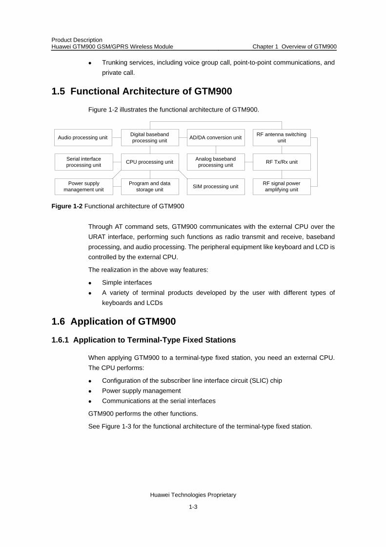
1.5 Functional Architecture of GTM900
Figure 1-2 illustrates the functional architecture of GTM900.
Digital basebandprocessing unit AD/DA conversion unit RF antenna switching
unit
Serial interfaceprocessing unit CPU processing unit Analog baseband
processing unit RF Tx/Rx unit
Power supplymanagement unit
Program and datastorage unit SIM processing unit RF signal power
amplifying unit
Audio processing unit
Figure 1-2 Functional architecture of GTM900
Through AT command sets, GTM900 communicates with the external CPU over the URAT interface, performing such functions as radio transmit and receive, baseband processing, and audio processing. The peripheral equipment like keyboard and LCD is controlled by the external CPU.
The realization in the above way features:
Simple interfaces A variety of terminal products developed by the user with different types of
keyboards and LCDs
1.6 Application of GTM900
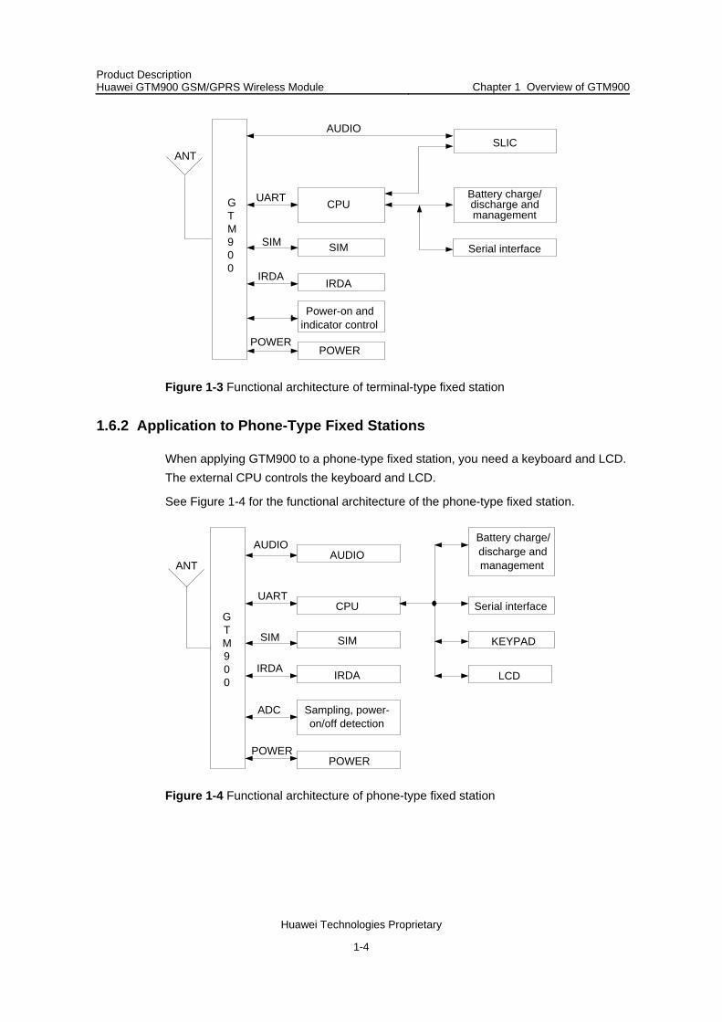
1.6.1 Application to Terminal-Type Fixed Stations
When applying GTM900 to a terminal-type fixed station, you need an external CPU. The CPU performs:
Configuration of the subscriber line interface circuit (SLIC) chip Power supply management Communications at the serial interfaces
GTM900 performs the other functions.
See Figure 1-3 for the functional architecture of the terminal-type fixed station.
1-3
Product Description Huawei GTM900 GSM/GPRS Wireless Module Chapter 1 Overview of GTM900
Huawei Technologies Proprietary
SIM SIM
IRDAIRDA
Power-on andindicator control
POWERPOWER
CPUUART Battery charge/discharge andmanagement
Serial interface
AUDIOSLIC
GTM900
ANT
Figure 1-3 Functional architecture of terminal-type fixed station
1.6.2 Application to Phone-Type Fixed Stations
When applying GTM900 to a phone-type fixed station, you need a keyboard and LCD. The external CPU controls the keyboard and LCD.
See Figure 1-4 for the functional architecture of the phone-type fixed station.
Battery charge/discharge andmanagement
KEYPAD
LCD
Serial interface
Sampling, power-on/off detection
ADC
CPUUART
AUDIO
SIMSIM
IRDA IRDA
POWERPOWER
GTM900
ANT
AUDIO
Figure 1-4 Functional architecture of phone-type fixed station
1-4
Product Description Huawei GTM900 GSM/GPRS Wireless Module Chapter 1 Overview of GTM900
Huawei Technologies Proprietary
1.6.3 Application to Vehicle-Mounted Stations and Public Telephones
The application of GTM900 to a vehicle-mounted station or a public telephone is the same to the above two applications. You may develop the wanted keyboards, LCDs, and other devices.
1-5

Product Description Huawei GTM900 GSM/GPRS Wireless Module Chapter 2 Interface Signals
Huawei Technologies Proprietary
Chapter 2 Interface Signals
2.1 About This Chapter
This chapter presents the interface signals of GTM900 from the following aspects:
Interfaces of Signal Connector on GTM900 Antenna Interface
2.2 Interfaces of Signal Connector on GTM900
2.2.1 Interface Signals
Table 2-1 lists the detailed description of the interface signals of GTM900.
Table 2-1 Interface signals
No. Signal I/O Interface level
Function Note
1 Batt+ I 4.0 V Supplying power --
2 Batt+ I 4.0 V Supplying power --
3 Batt+ I 4.0 V Supplying power --
4 Batt+ I 4.0 V Supplying power --
5 Batt+ I 4.0 V Supplying power --
6 GND O/I -- Providing working ground --
7 GND O/I -- Providing working ground --
8 GND O/I -- Providing working ground --
9 GND O/I -- Providing working ground --
10 GND O/I -- Providing working ground --
11 RXD2 at the infrared serial interface
O 3.0 V Serial interface for traffic control, supporting adaptive rate
--
12 TXD2 at the infrared serial interface
I 3.0 V Serial interface for traffic control, supporting adaptive rate
--
13 VDD O -- Signal indication of normally started GTM900
--
14 ADC I -- A/D conversion 10bits 0-3V
2-1

Product Description Huawei GTM900 GSM/GPRS Wireless Module Chapter 2 Interface Signals
Huawei Technologies Proprietary
No. Signal I/O Interface level
Function Note
15 PWON I 3.0 V Power-on control signals triggered only at low level
--
16 UART_DSR O 3.0 V Indicating whether the serial interface is ready
--
17 UART_RI O 3.0 V Ringer indication of the serial interface for use as call display and hang-up indication
--
18 UART_RXD O 3.0 V Receive signals at PC serial interfaces
--
19 UART_TXD I 3.0 V Transmit signals at PC serial interfaces
--
20 UART_CTS O 3.0 V Receive Request message delivered over the PC serial interface for traffic control
--
21 UART_RTS I 3.0 V Transmit Ready message delivered over the PC serial interface for traffic control
--
22 UART_DTR I 3.0 V Signal indication that the PC serial interface is ready
--
23 UART_DCD O 3.0 V Carrier detection --
24 SIM_CD I 3.0V Input signals indicating whether the SIM card is configured
--
25 SIM_RST O 3.0 V Output signals to reset the SIM card
--
26 SIM_DATA I/O 3.0 V Input interface and output interface of the SIM card
--
27 SIM_CLK O 3.0 V Clock signals of the SIM card provided by the baseband chip
--
28 SIM_VCC O 3.0 V Output signals supplying power to the SIM card
--
29 SIM_GND O/I -- Earth signal of SIM card --
30 Vbackup O/I 3.0 V Standby battery of GTM900 --
31 RST I -- Reset signal --
32 LPG O -- Mainly controls the status of the indicator.
--
33 AUXO+ O -- Hands-free audio output signals+
--
34 AUXO- O -- Hands-free audio output signals–
--
2-2
Product Description Huawei GTM900 GSM/GPRS Wireless Module Chapter 2 Interface Signals
Huawei Technologies Proprietary
No. Signal I/O Interface level
Function Note
35 EAR+ O -- Receiver audio output signals+ --
36 EAR- O -- Receiver audio output signals– --
37 MIC+ I -- Receiver audio input signals+ --
38 MIC- I -- Receiver audio input signals– --
39 AUXI+ I -- Hands-free audio input signals+ --
40 AUXI- I -- Hands-free audio input signals– --
Note:
The signals at the serial interfaces are named with PC as the DCE(Data Communications Equipment).
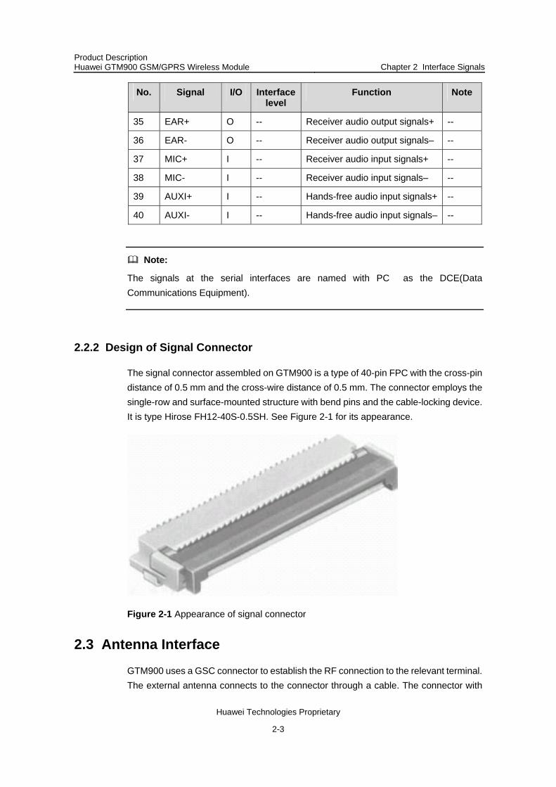
2.2.2 Design of Signal Connector
The signal connector assembled on GTM900 is a type of 40-pin FPC with the cross-pin distance of 0.5 mm and the cross-wire distance of 0.5 mm. The connector employs the single-row and surface-mounted structure with bend pins and the cable-locking device. It is type Hirose FH12-40S-0.5SH. See Figure 2-1 for its appearance.
Figure 2-1 Appearance of signal connector
2.3 Antenna Interface
GTM900 uses a GSC connector to establish the RF connection to the relevant terminal. The external antenna connects to the connector through a cable. The connector with
2-3

Product Description Huawei GTM900 GSM/GPRS Wireless Module Chapter 2 Interface Signals
Huawei Technologies Proprietary
the part number of MM9329-2700 is provided by Murata. See the dimensions illustrated in Figure 2-2.
Figure 2-2 Dimensions of antenna connector (unit: mm)
2-4
Product Description Huawei GTM900 GSM/GPRS Wireless Module Chapter 3 Electrical Characteristics of Interfaces
Huawei Technologies Proprietary
Chapter 3 Electrical Characteristics of Interfaces
3.1 About This Chapter
This chapter presents the electrical characteristics of the interfaces of GTM900 from the following aspects:
Absolute Maximum Ratings Recommended Operating Conditions Power Supply Characteristics
Note:
This chapter focuses on the electrical characteristics of the interfaces on GTM900 for external services, not including the power supply part.
3.2 Absolute Maximum Ratings
See Table 3-1 for the absolute maximum ratings of GTM900.
Table 3-1 Absolute maximum ratings of GTM900
Parameter Description Min. Max. Unit
Ts Storage temperature –40 +70 °C
Vi Input or output signal voltage on any of the pins.
–0.5 3.5 V
IIN Input current -- 100 mA
VESD Electrostatic voltage -- ±2000 V
Note:
“Vi” in Table 3-1 refers to common I/O pins, not including the power supply pins. The maximum input voltage of a power supply pin is 4.8 V.
3.3 Recommended Operating Conditions
See Table 3-2 for the recommended operating conditions of GTM900.
3-1

Product Description Huawei GTM900 GSM/GPRS Wireless Module Chapter 3 Electrical Characteristics of Interfaces
Huawei Technologies Proprietary
Table 3-2 Recommended operating conditions of GTM900
Parameter Description Min. Max. Unit
VIH High level input voltage 1.85 3.14 V
VIH Low level input voltage –0.3 0.9 V
IIH Leakage current of high level input voltage
-- 2 uA
IIL Leakage current of low level input voltage
–2 -- uA
VOH High level output voltage 2.39 3.00 V
VOL Low level output voltage 0 0.45 V
CIN Input capacitance -- 15 pF
3.4 Power Supply Characteristics
3.4.1 Input Power
Table 3-3 lists the values for the input power of GTM900.
Table 3-3 Values for input power of GTM900
Parameter Min. Typical Max. Unit
VBatt+ 3.3 4 4.8 V
3.4.2 Operating Current
Table 3-4 lists the values for the operating current of GTM900.
Table 3-4 Values for operating current of GTM900
Operating mode
Parameter Min. Max. Unit
Idle Ireg -- 4.0 mA
Conversation Ireg -- 250 mA
3-2
Product Description Huawei GTM900 GSM/GPRS Wireless Module Chapter 4 Interface Application
Huawei Technologies Proprietary
Chapter 4 Interface Application
4.1 About This Chapter
This chapter presents the application of the interfaces from the following aspects:
UART Interface SIM Interface Audio Interface Ringer Interface Power Supply Interface
4.2 UART Interface
The UART interface realizes serial communications with external devices, supporting level input and level output at 3.00 V (VDD_MSM_P).
All the signals over the UART interface are triggered at low level except RXD and TXD. The latter two are triggered at high level.
The UART interface supports both transmit FIFO (First In First Out) and receive FIFO at 512 byte, programmable data width, programmable data stop bit, and programmable parity check or non check. The maximum rate the UART interface supports is 115.2 kbps. The default rate is 9600 bps.
See Table 4-1 for detailed description of the UART interface signals.
Table 4-1 Signals over UART interface
No. Signal name Description Characteristic Direction
23 UART_DCD Carrier detection Data links already connected
DCE-DTE
17 UART_RI Ringer indication Notifying DTE of remote call-in
DCE-DTE
20 UART_RTS Request transmit DTE sends Request transmit message to DCE
DTE-DCE
18 UART_TXD Transmit data DTE transmits data DTE-DCE
16 UART_DSR Data services ready
DCE is ready for data services
DCE-DTE
22 UART_DTR Data terminal ready
DTE is ready DTE-DCE
21 UART_CTS Clear transmit DCE is switched to the Rx mode
DCE-DTE
4-1

Product Description Huawei GTM900 GSM/GPRS Wireless Module Chapter 4 Interface Application
Huawei Technologies Proprietary
No. Signal name Description Characteristic Direction
19 UART_RXD Receive data DTE receives serial data
DCE-DTE
6 GND GND -- --
For the output signals, GTM900 can be directly connected to an external drive device operating at 3.3 V. If the input signals exceed the value range of GTM900, they must undergo level alignment.
4.3 SIM Interface
GTM900 can be connected to an external SIM card operating at 3.0 V. See Table 4-2 for the signals over the SIM interface.
Table 4-2 Signals over SIM interface
No. Signal name Description
27 SIM_CLK Clock signals over the SIM interface
25 SIM_RST Reset signals over the SIM interface
26 SIM_DATA Data lines of the SIM card
28 SIM_VCC Power supply to the SIM card
24 SIM_CD SIM card configured
29 SIM_GND SIM card grounded
4.4 Audio Interface
GTM900 supports two channels of audio input signals and audio output signals. The two types of signals are both differential ones. In practice, you may use one channel or both. See Figure 4-1 and Table 4-2 for the two channels of input signals and output signals.
4-2

Product Description Huawei GTM900 GSM/GPRS Wireless Module Chapter 4 Interface Application
Huawei Technologies Proprietary
Figure 4-1 Connection between audio input signals and output signals on first channel
Figure 4-2 Connection between audio input signals and output signals on seconchannel
d
Note:
The maximum power of the audio signals output to the 32 Ω loudspeaker on the first channel is 33 mW, and that of the audio signals output to the 1 kΩ loudspeaker on the second channel is 4 mW.
4-3

Product Description Huawei GTM900 GSM/GPRS Wireless Module Chapter 4 Interface Application
Huawei Technologies Proprietary
See Table 4-3 for the signals over the Audio interface.
Table 4-3 Signals over Audio interface
No. Signal name Description
33 AUXO+ Handsfree audio output signal+
34 AUXO- Handsfree audio output signal–
39 AUXI+ Handsfree audio input signal+
40 AUXI- Handsfree audio input signal–
35 EAR+ Handheld audio output signal+
36 EAR- Handheld audio output signal–
37 MIC+ Handheld audio input signal+
38 MIC- Handheld audio input signal–
4.5 Ringer Interface
If you drive an external ringer with the Ringer signals, you shall need an external drive circuit. See Figure 4-3 for the drive circuit of the Ringer signals.
Figure 4-3 Drive circuit of Ringer signals
4-4
Product Description Huawei GTM900 GSM/GPRS Wireless Module Chapter 4 Interface Application
Huawei Technologies Proprietary
4.6 Power Supply Interface
The external power supply to GTM900 is 4.0 V. In practice, the voltage range can be from 3.3 V to 4.8 V.
4-5

Product Description Huawei GTM900 GSM/GPRS Wireless Module Chapter 5 Operating Process
Huawei Technologies Proprietary
Chapter 5 Operating Process
5.1 About This Chapter
This chapter presents the operating process of GTM900 from the following aspects:
Powering on/off GTM900 Software Upgrade of GTM900 Data Services Services Presentation Diagram of GTM900
5.2 Powering on/off GTM900
5.2.1 Powering UP GTM900
When the power supply to GTM900 is higher than 3.3 V and the PWON signal is low level, GTM900 operates as illustrated in Figure 5-1.
4.0 V
2.8 V
3.3 V
PWON
VBATT+
VDD
Figure 5-1 Relationship between VDD and PWON signal
5.2.2 Powering Down GTM900
GTM900 might be powered down in the two cases below:
I. Powering down GTM900 normally
During normal powering down of GTM900, the external CPU lowers the level of PWON signal level for 2 to 3 seconds to put GTM900 into normal powering down procedure. In this case, GTM900 can save relevant information and completes network deregistration.
5-1
Product Description Huawei GTM900 GSM/GPRS Wireless Module Chapter 5 Operating Process
Huawei Technologies Proprietary
II. Powering down GTM900 in emergencies
Through AT commands, the external CPU powers off GTM900 directly.
5.3 Software Upgrade of GTM900
GTM900 supports software upgrade. You may upgrade the software of GTM900 over the serial interface. For detailed operations, see the operation manual.
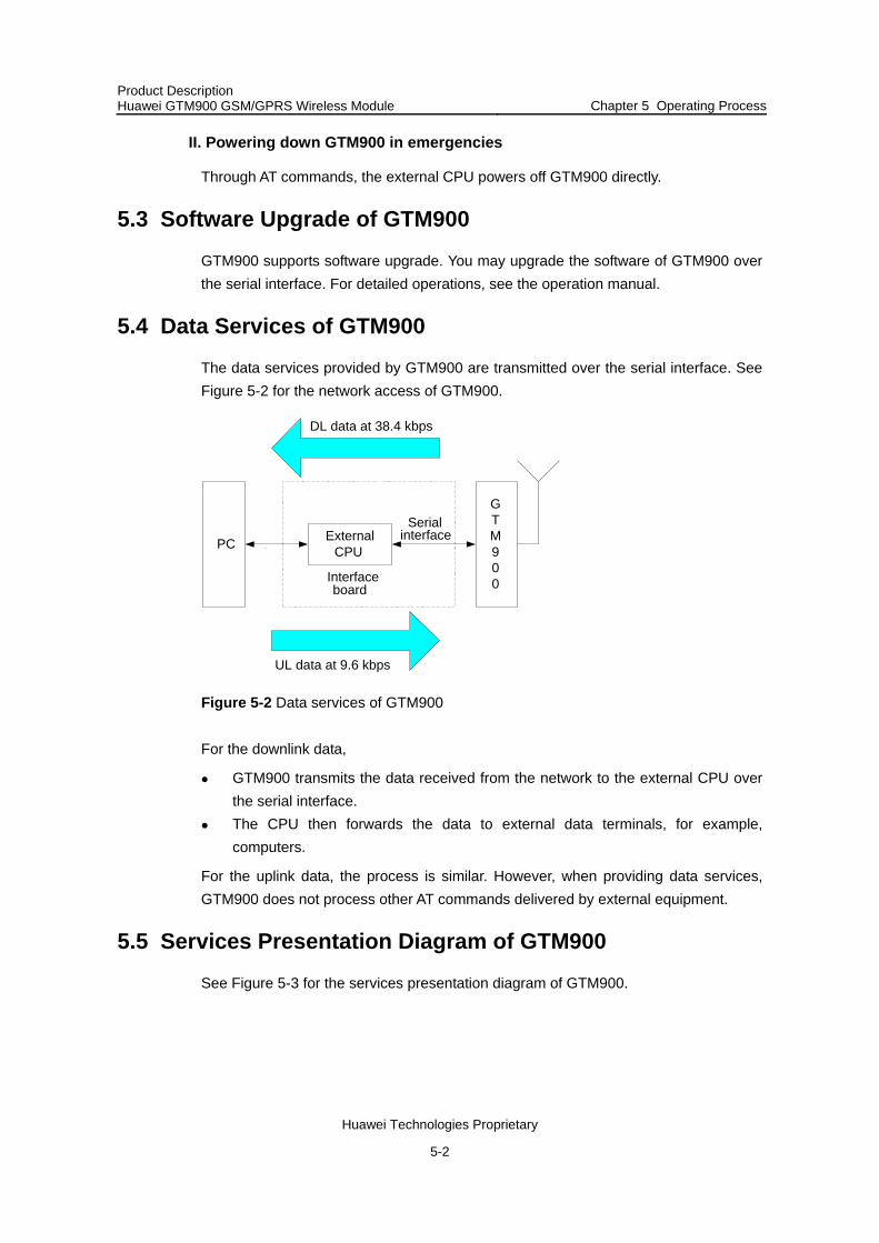
5.4 Data Services of GTM900
The data services provided by GTM900 are transmitted over the serial interface. See Figure 5-2 for the network access of GTM900.
UL data at 9.6 kbps
PCSerial
interfaceExternalCPU
Interfaceboard
DL data at 38.4 kbps
GTM900
Figure 5-2 Data services of GTM900
For the downlink data,
GTM900 transmits the data received from the network to the external CPU over the serial interface.
The CPU then forwards the data to external data terminals, for example, computers.
For the uplink data, the process is similar. However, when providing data services, GTM900 does not process other AT commands delivered by external equipment.
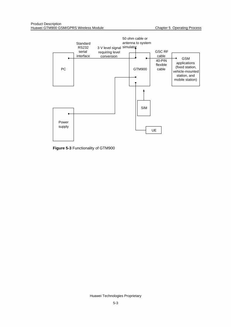
5.5 Services Presentation Diagram of GTM900
See Figure 5-3 for the services presentation diagram of GTM900.
5-2
Product Description Huawei GTM900 GSM/GPRS Wireless Module Chapter 5 Operating Process
Huawei Technologies Proprietary
3 V level signalrequiring level
conversion
StandardRS232serial
interface
PC GTM900
Powersupply
GSMapplications(fixed station,
vehicle-mountedstation, and
mobile station)
50 ohm cable orantenna to systemsimulator
40-PINflexiblecable
GSC RFcable
SIM
UE
Figure 5-3 Functionality of GTM900
5-3

Product Description Huawei GTM900 GSM/GPRS Wireless Module Chapter 6 Acronyms and Abbreviations
Huawei Technologies Proprietary
Chapter 6 Acronyms and Abbreviations
ADC Analog-to-Digital Converter
AFC Automatic Frequency Control
AGC Automatic Gain Control
ARFCN Absolute Radio Frequency Channel Number
ARP Antenna Reference Point
BER Bit Error Rate
BTS Base Transceiver Station
CS Coding Scheme
CSD Circuit Switched Data
CE Conformité Européene (European Conformity)
DSP Digital Signal Processor
DTR Data Terminal Ready
DTX Discontinuous Transmission
EFR Enhanced Full Rate
EMC Electromagnetic Compatibility
ESD Electrostatic Discharge
GMSK Gaussian Minimum Shift Keying
GPRS General Packet Radio Service
HiZ High Impedance
HR Half Rate
IMEI International Mobile Equipment Identity
FDMA Frequency Division Multiple Access
ISO International Standards Organization
ITU International Telecommunications Union
LED Light Emitting Diode
MO Mobile Originated
MMI Man Machine Interface
MT Mobile Terminated
NTC Negative Temperature Coefficient
PDU Protocol Data Unit
6-1

Product Description Huawei GTM900 GSM/GPRS Wireless Module Chapter 6 Acronyms and Abbreviations
Huawei Technologies Proprietary
PPP Point-to-point protocol
RAM Random Access Memory
SAR Specific Absorption Rate
SELV Safety Extra Low Voltage
UART Universal asynchronous receiver-transmitter
ZIF Zero Insertion Force
VSWR Voltage Standing Wave Ratio
6-2


