Author: If the sum of the calculation (usedFreqRelThresh2fRscp + usedFreqThresh2dRscp) exceeds the maximum 3GPP value -25dBm, the value sent to the UE will be -25dBm.
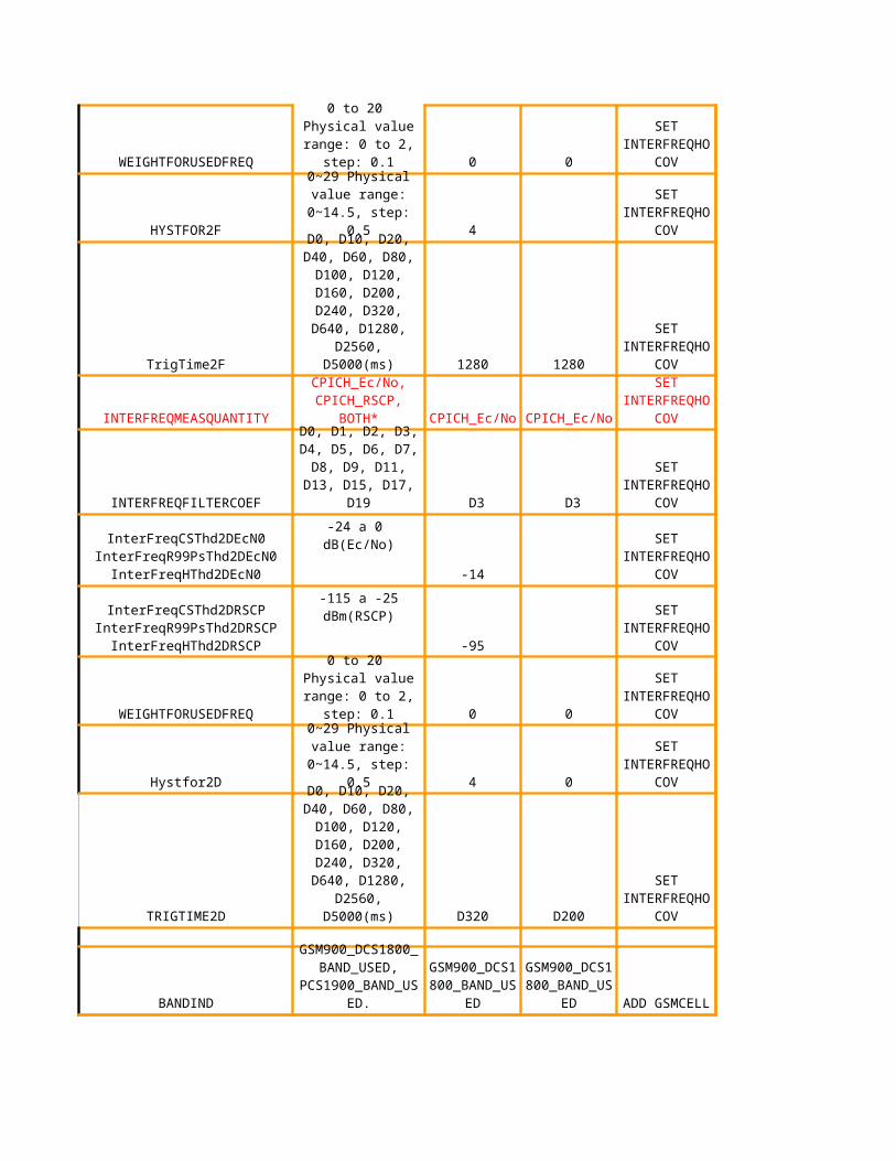
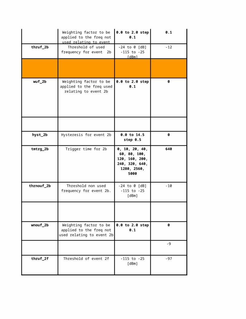
usedFreqW2f 0
hysteresis2f 0
1280
measQuant4_2b 2
filterCoeff4_2b 2
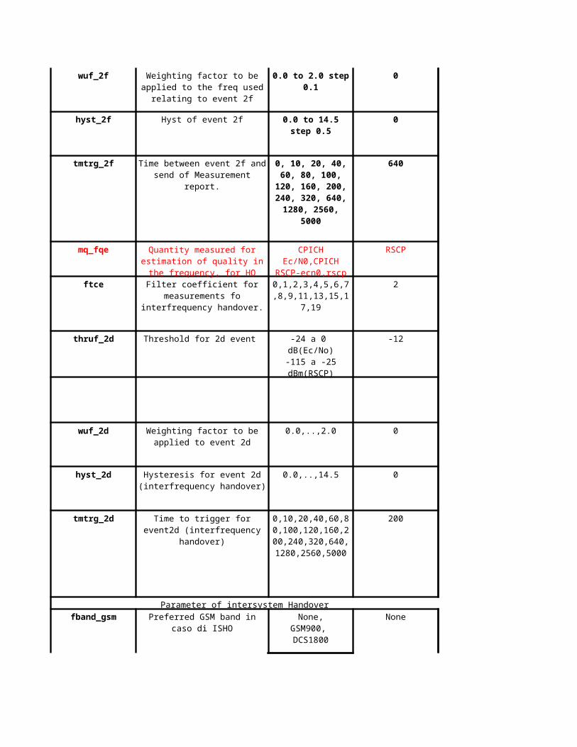
usedFreqThresh2dEcno -12
usedFreqThresh2dRscp -104
usedFreqW2d 0
hysteresis2d 0
200
#N/A #N/A
bandIndicator DCS1800 = 0
timeToTrigger2fEcnotimeToTrigger2fRscp
timeToTrigger2dEcnotimeToTrigger2dRscp
#N/A #N/A
usedFreqThresh2dRscp -95
usedFreqW2d #N/A
hysteresis2d 0
#N/A #N/A
200
measQuantity2 Ec/No
#N/A #N/A
usedFreqThresh2dEcno -12
usedFreqThresh2dRscp -104
hysteresis2f 0
timeToTrigger2dEcnotimeToTrigger2dRscp
1280
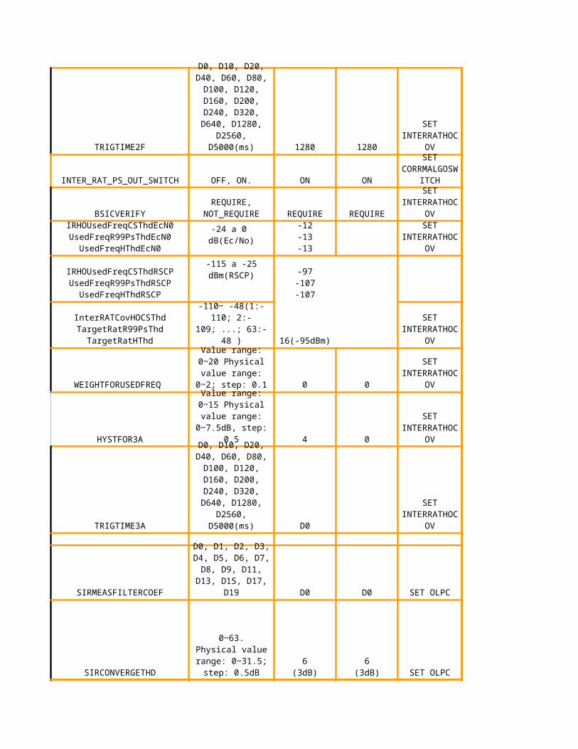
fddGsmHOSupp On
#N/A #N/A
utranRelThresh3aEcno 2
utranRelThresh3aRscp 3
gsmThresh3a -95
utranW3a 0
hysteresis3a 0
timeToTrigger3a 6
#N/A #N/A
#N/A #N/A
#N/A #N/A
timeToTrigger2fEcnotimeToTrigger2fRscp
M60
Author: 100ms
#N/A #N/A
#N/A #N/A
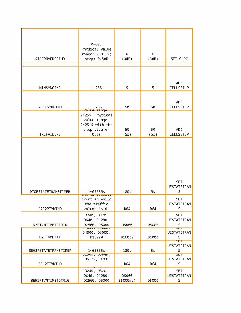
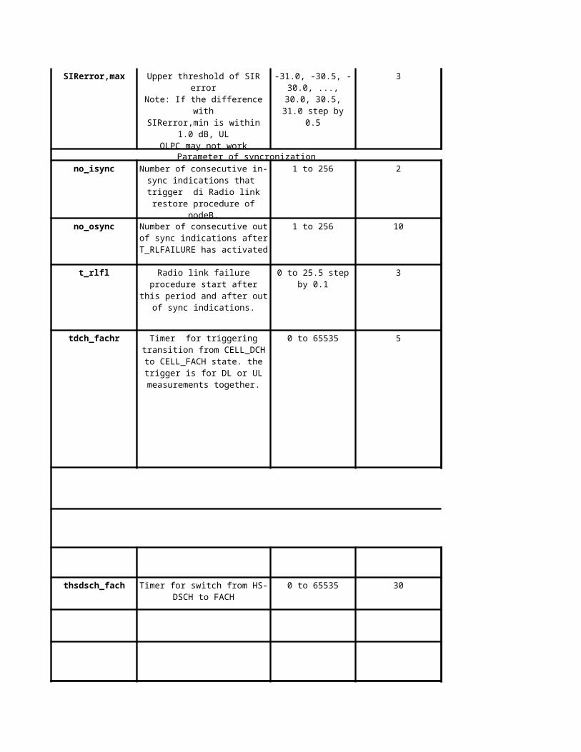
nInSyncInd 3
nOutSyncInd 10
rlFailureT 10
downswitchTimer 10
#N/A #N/A
Time during which throughput has to be low in order to
trigger a downswitch (dedicated to common
substate) for a UE in state DCH/DCH. If
downswitchTimer is set to 0, no downswitches will be
issued, irrespective of user throughput.
#N/AhsdschInactivityTimer
Time during which throughput has to be low in order to
trigger a downswitch (dedicated to common
#N/A2s
J69
Author: triggered when downswitchThreshold=3kbps below threshold AND doesn’t increase above downswitchTimerThreshold=3kbps
M69
Author: 1s
J73
Author: triggered when downswitchThreshold below threshold AND doesn’t increase above downswitchTimerThreshold
#N/A
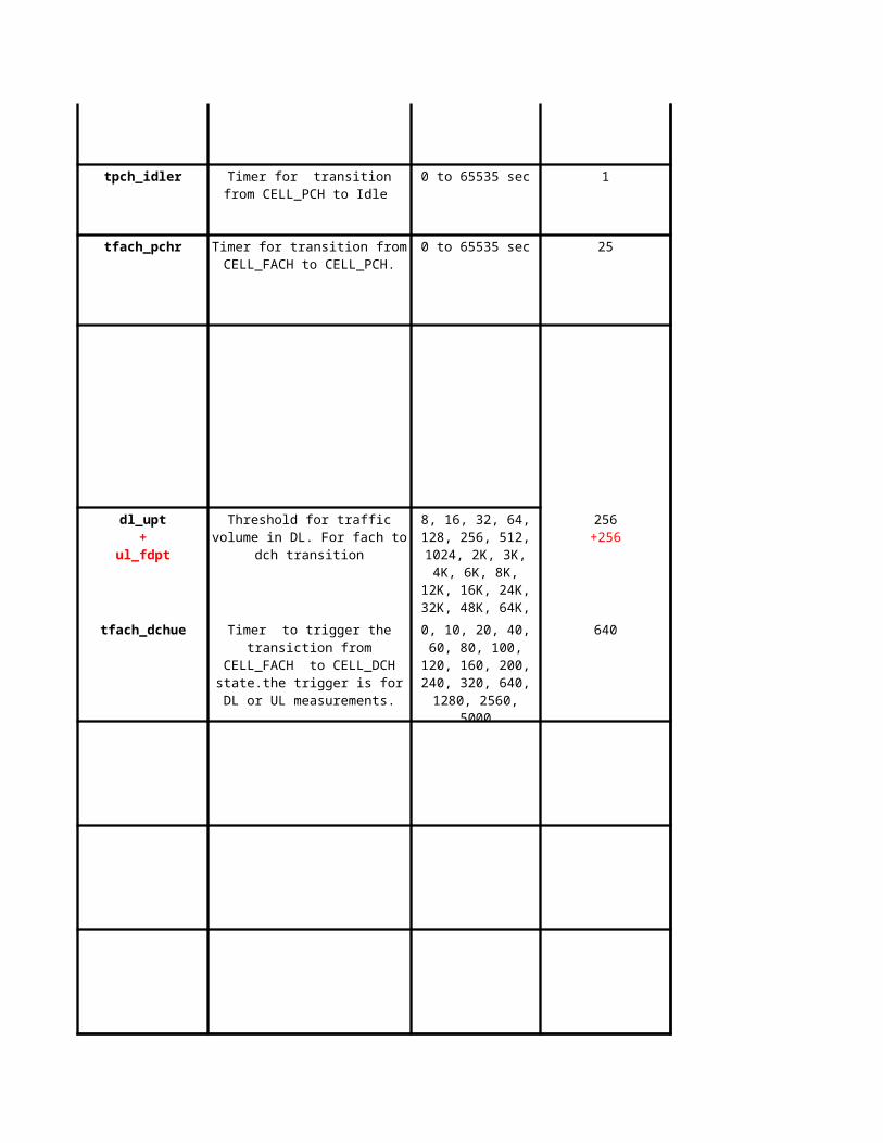
#N/AinactivityTimerPch
Timer for sending of IU RELEASE REQUEST
message to CN for UE in state URA_PCH
#N/A30s
#N/AinactivityTimer
Time, without data transmission, after which a UE
in state CELL_FACH is switched down to state
URA_PCH. If URA_PCH state is not available the UE is
#N/A30min
dlRlcBufUpswitch+
ulRlcBufUpswitch
100bytes500bytes (DL)+256bytes(UL)
#N/A
Fach to Dch timer not exist, use only rlc buffer
line#82
J81
Author: Red added by Maxis
M81
Author: red added by Maxis 100bytes mapped wrongly
#N/A #N/A
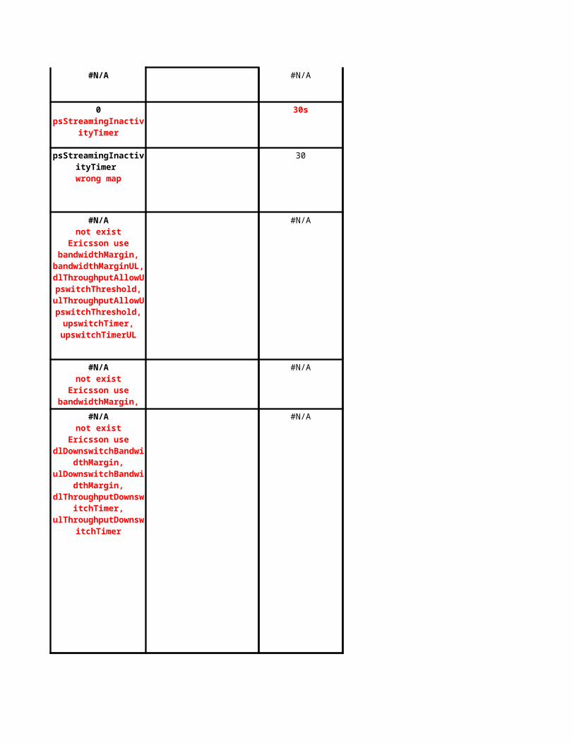
30s
30
#N/A
#N/A
#N/A
0psStreamingInactivityTi
mer
psStreamingInactivityTimer
wrong map
#N/Anot exist
Ericsson use bandwidthMargin,
bandwidthMarginUL,dlThroughputAllowUpswitc
hThreshold, ulThroughputAllowUps
witchThreshold, upswitchTimer,
upswitchTimerUL
#N/Anot exist
Ericsson use bandwidthMargin,
bandwidthMarginUL,dlThroughputAllowUpswitc#N/A
not existEricsson use
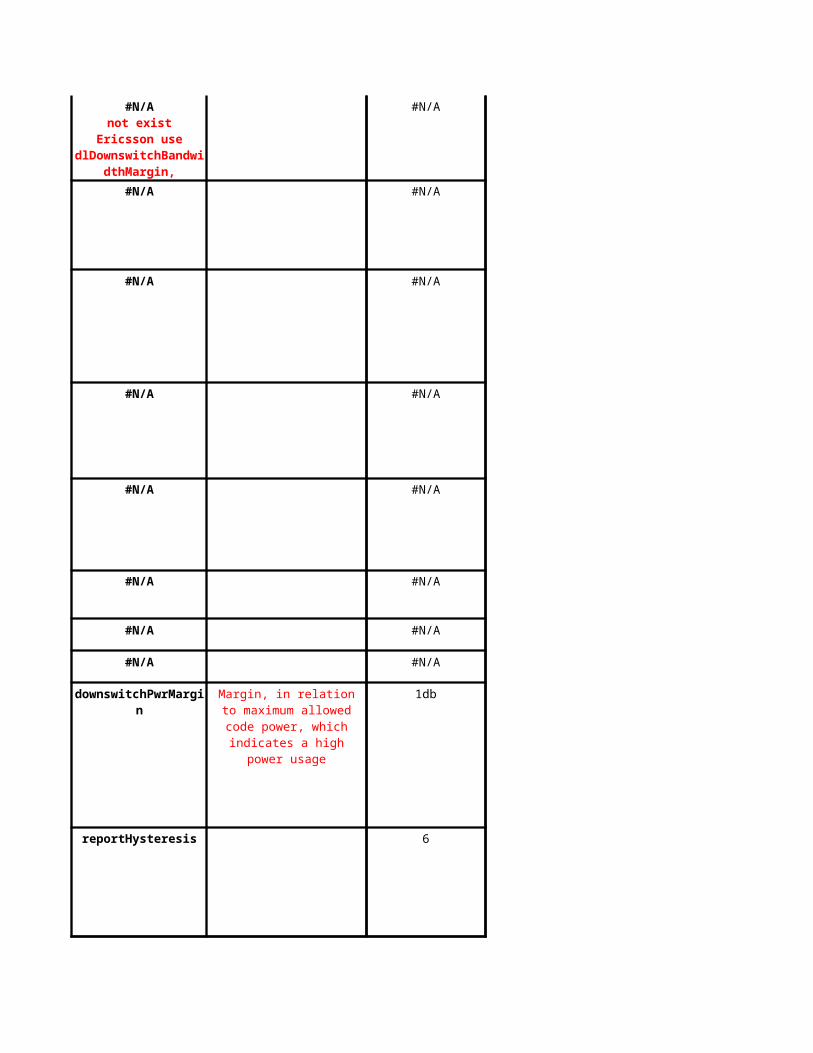
dlDownswitchBandwidthMargin,
ulDownswitchBandwidthMargin,
dlThroughputDownswitchTimer,
ulThroughputDownswitchTimer
#N/A
#N/A #N/A
#N/A #N/A
#N/A #N/A
#N/A #N/A
#N/A #N/A
#N/A #N/A
#N/A #N/A
downswitchPwrMargin 1db
reportHysteresis 6
#N/Anot exist
Ericsson use dlDownswitchBandwidt
hMargin, ulDownswitchBandwidt
Margin, in relation to maximum allowed code power, which
indicates a high power usage
J100
Author: together with coverageTimer (line 103) to trigger coverage limited downswitch
M100
Author: 1 dB lower than max code pwr
#N/A #N/A
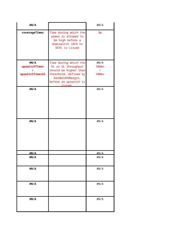
coverageTimer 1s
#N/A #N/A
#N/A #N/A
#N/A #N/A
#N/A #N/A
#N/A #N/A
#N/A #N/A
#N/A #N/A
Time during which the power is allowed to be high before a downswitch (DCH to DCH) is
issued
#N/AupswitchTimer
+upswitchTimerUl
Time during which the DL or UL throughput should be
higher than threshold, defined by bandwidthMargin, before
an upswitch is issued.
#N/A500ms
+500ms
J104
Author: refer to line 121 for threshold
#N/A #N/A
#N/A #N/A
#N/A #N/A
#N/A #N/A
#N/A #N/A
#N/A #N/A
#N/A #N/A
#N/A #N/A
#N/A #N/A
upswitchPwrMargin 3db
#N/A #N/A
#N/A #N/A
#N/A #N/A
#N/A #N/A
#N/A #N/A
filterCoefficient1 2
Upswitch (DCH to DCH) power margin. Upswitch power threshold is = Max Code Pwr -
downswitchPwrMargin - relative power increase -
upswitchPwrMargin
Coefficient for layer 3 filtering before intra-frequency reporting evaluation
J121
Author: timer for coverage test before upwitch
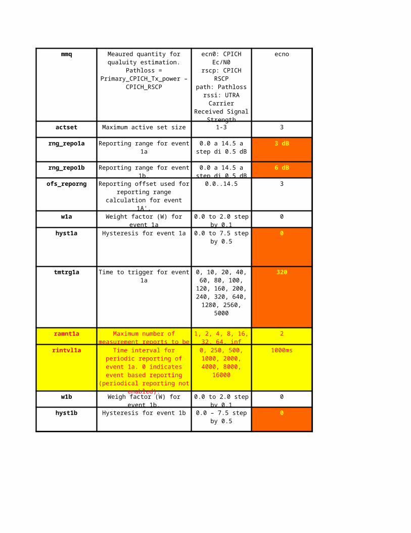
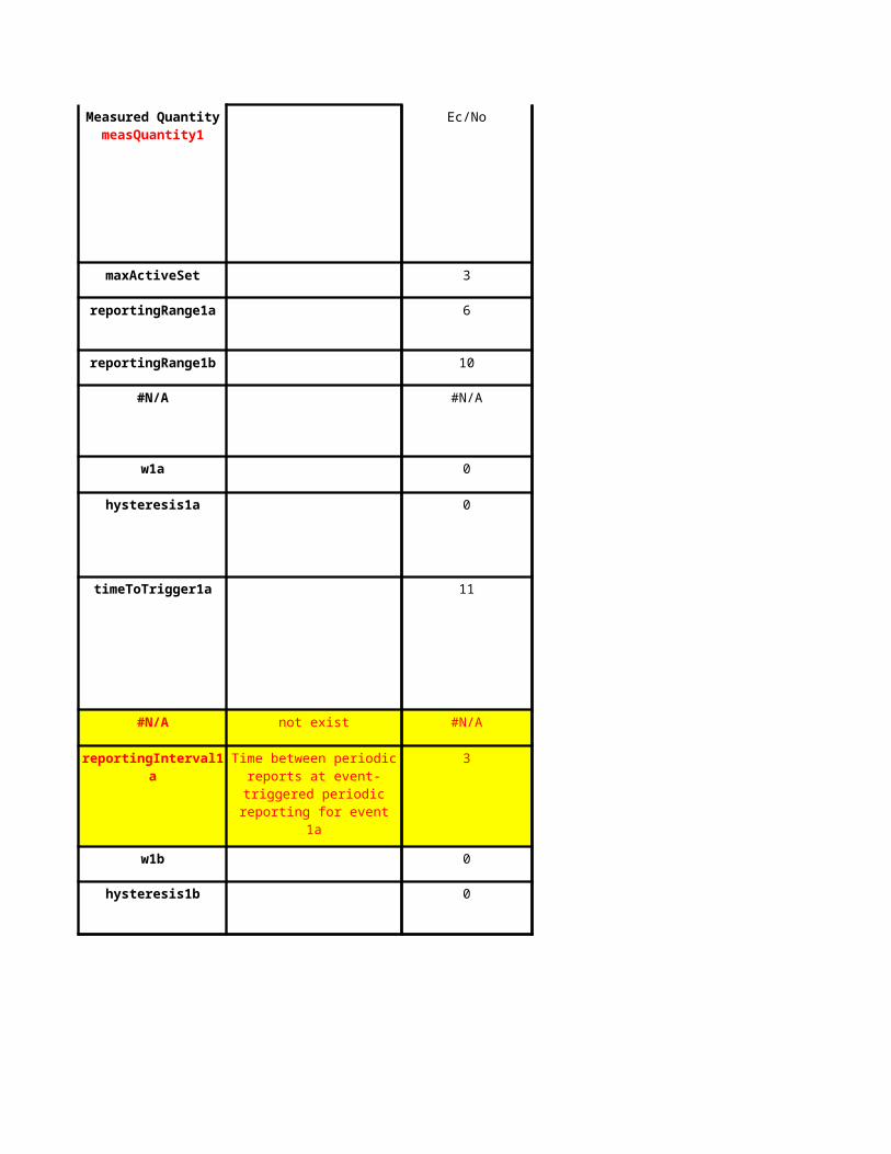
Ec/No
maxActiveSet 3
reportingRange1a 6
reportingRange1b 10
#N/A #N/A
w1a 0
hysteresis1a 0
timeToTrigger1a 11
#N/A not exist #N/A
reportingInterval1a 3
w1b 0
hysteresis1b 0
Measured QuantitymeasQuantity1
Time between periodic reports at event-triggered periodic
reporting for event 1a
M130
Author: 6 = 3dB
M133
Author: 10 = 5dB
M139
Author: 320ms
M142
Author: 1s
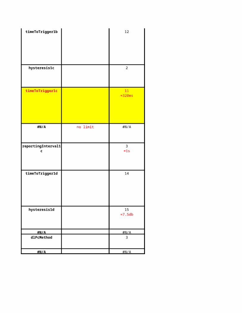
timeToTrigger1b 12
hysteresis1c 2
timeToTrigger1c
#N/A no limit #N/A
reportingInterval1c
timeToTrigger1d 14
hysteresis1d
#N/A #N/A
dlPcMethod 3
#N/A #N/A
11=320ms
3=1s
15=7.5db
M148
Author: 640ms
M153
tanbk: 2560ms
M156
Author: balancing
#N/A #N/A
#N/A #N/A
#N/A #N/A
#N/A #N/A
#N/A #N/A
#N/A #N/A
#N/A #N/A
#N/A #N/A
#N/A #N/A
#N/A #N/A
#N/A #N/A
#N/A #N/A
Maxis
Maxis Optimized Value
For huawei this parameter is per neighbour basis
Not exists in HW
Not exists in HW
Not exists in HW
Not exists in HW
Not exists in HW
Not exists in HW
Not exists in HW
Different algorithm
only for 4b event
N66
Author: follow ericsson for swap
Suggest to keep it disable
Suggest to keep it disable
Suggest to keep it disable
Suggest to keep it disable, this is for Cell_pch to URA_Pch
Not using PS Streaming RAB - to keep default
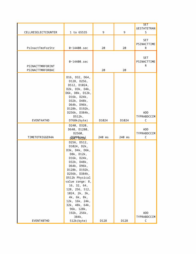
Huawei = 9 times within 180s (CellReSelectTimer) Siemens = 20 times no timer involvedEricsson = no cell_pch
what is the difference btw this and DTOFSTATETRANSTIMER - differentdaniel to check this parameter
follow Huawei, no need to map
follow Huawei, no need to map
follow Huawei, no need to map
64/64
no need to map
follow Huawei, no need to map
follow Huawei, no need to map
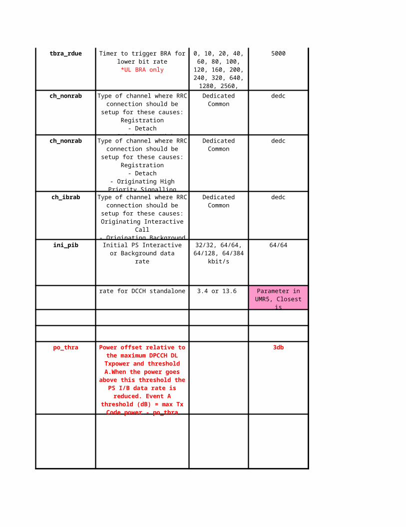
For PS only to trigger downswitch/upswitch. Per dpcch basis
Event E = TCP above threshold,can trigger downswitch if Event A satisfiesEvent A = BLER above threshold, both Event E & F will consider event AEvent F = TCP below threshold, upswitch allowed
For F event.
Same as po_thra, this is for IuR (Siemens specific)
Not used, propose no need to map
Repeat from line 100, propose to delete
Same as thrh_f, this is for IuR (Siemens specific)
??? What does this means?
Repeat from line 104, propose to delete
Repeat from line 103, propose to delete
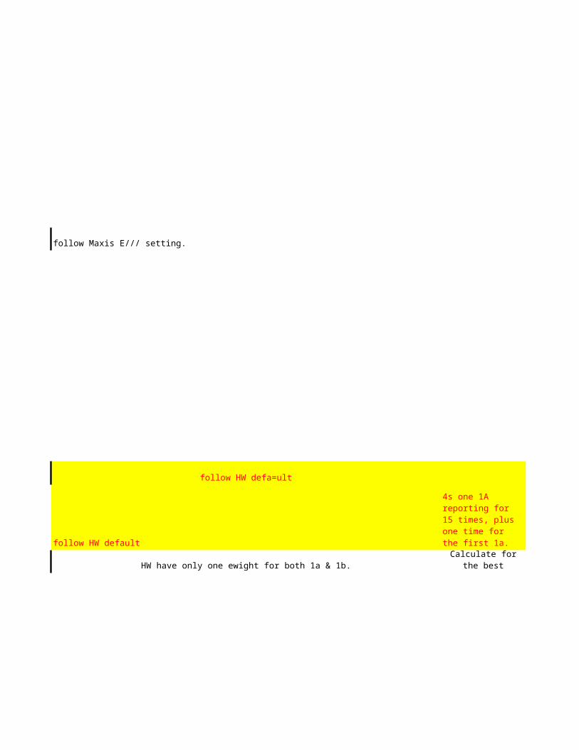
follow Maxis E/// setting.
follow HW defa=ult
follow HW default
HW have only one ewight for both 1a & 1b.
HW default
change to 4 times in every 4s
HW default
follow HW default
follow HW default. Will perform power balancing for multiple radio link.HW default ( every 2 frames)
follow HW default. If best cell detected for 1d, it will be change to be the serving cell for HSDPA, that's y the timer is 640ms.
HW default
HW default
HW default
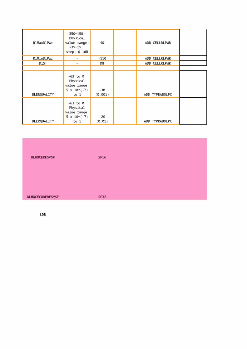
turn on all 3 if want to enable the LDR switch.
UU means radio interface between UE to RNC- could means load ( UL -RTWP, DL- power).
to be used on 2nd carrier cells.
to be used on 3nd carrier cells.
Maxis
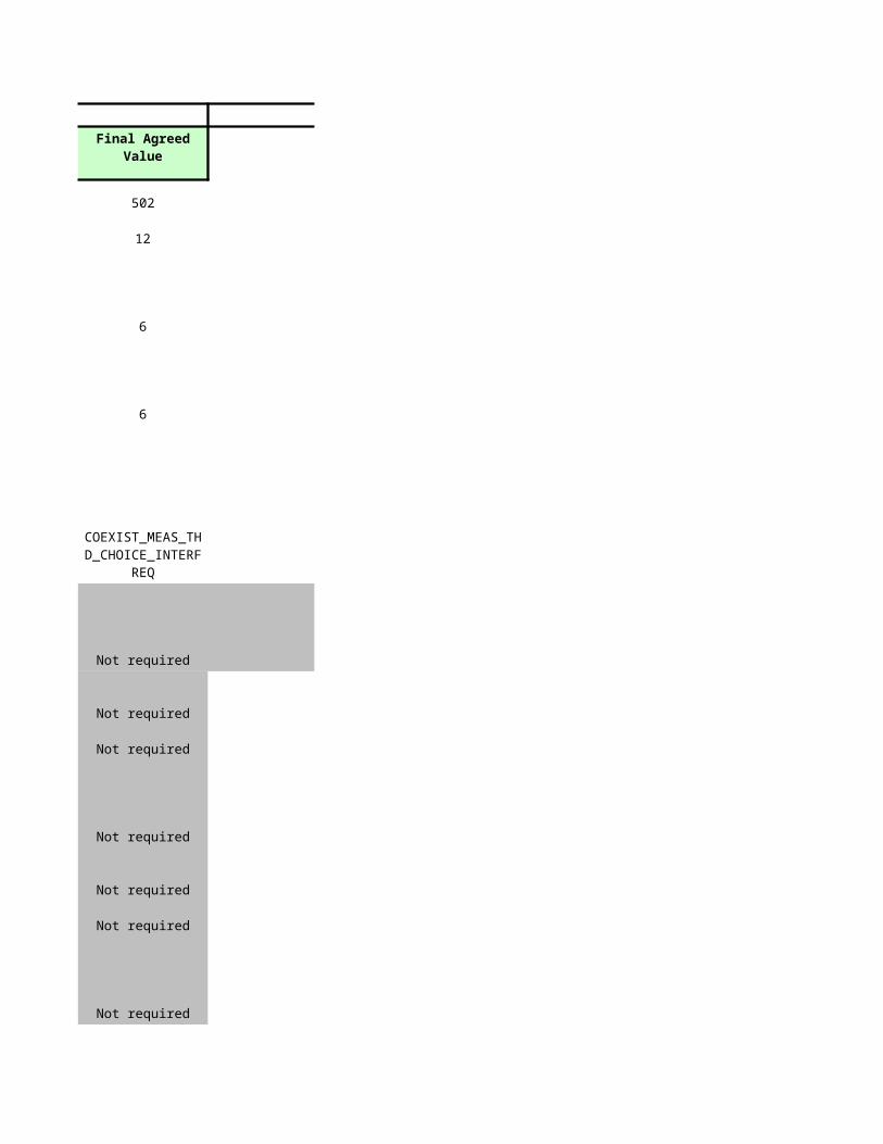
Discuss Final Agreed Value
502
12
6
6
Not required
Not required
Not required
Not required
Not required
Not required
Not required
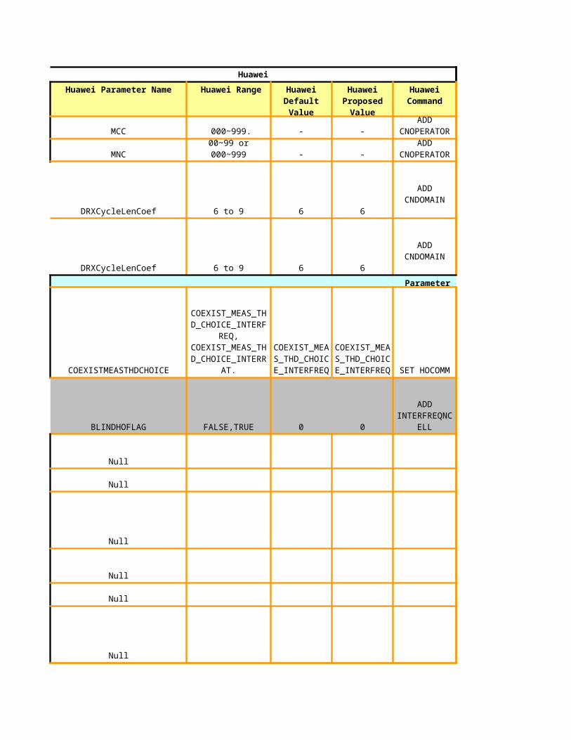
COEXIST_MEAS_THD_CHOICE_INTERFR
EQ
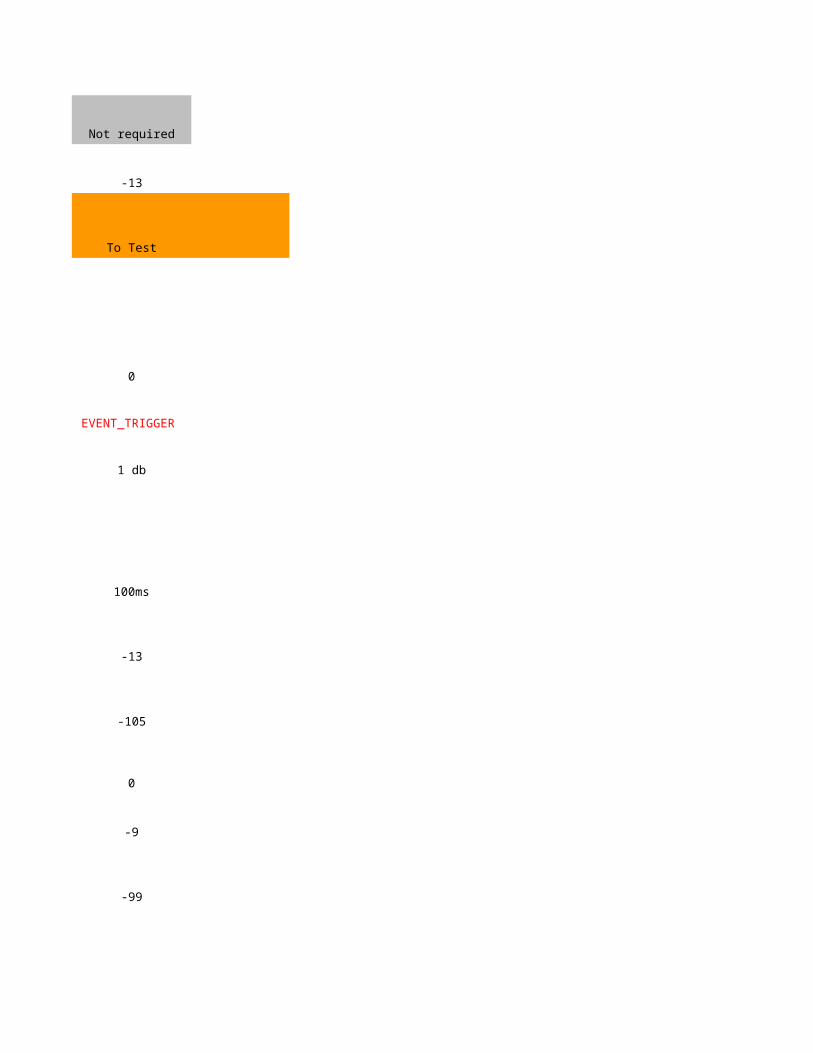
Not required
-13
To Test
0
EVENT_TRIGGER
1 db
100ms
-13
-105
0
-9
-99
0
0
1280
CPICH_Ec/No
D3
-12
-102
0
0
200ms
GSM900_DCS1800_BAND_USED
-12
-102
0
0
D3
200ms
CPICH_RSCP
EVENT_TRIGGER
-9
-97
2(1db)
to provide hw with gsm cell dump, gprs or
edge
1280ms
ON
REQUIRE
-10
-100
-95
0
0
60ms
D0
3db
3
10
1s
180s
5s
64byte
D640ms
D1000ms
D1024
240ms
D1024
240ms
Huawei to check whether Pch is enable
or disable
Huawei to check whether Pch is enable
or disable
Huawei to check whether Pch is enable
or disable
Huawei to check whether Pch is enable
or disable
P81
tanbk: HW to check whether can trigger F to D by UL RLC buffer Huawei Confirm: 4/06:- trigger is by UL or DL
Suggest to keep it di 9
20s
Zero user data throug 20s
follow huawei, per rab basis
follow huawei, per rab basis
follow huawei, per rab basis
P88
tanbk: follow huawei default
FACH
64/64
3_RATES
3_RATES
1 (0.5 dB)
1 (0.5 dB)
follow huawei, per rab basis
DCH_13.6K_SIGNALLING
DCH_13.6K_SIGNALLING
As long as Ea & A fullfills, the PS rate will be reducted.
D64
D64
NA
NA
NA
NA
20(2dB)
64(640ms)
64(640ms)
NA
NA
NA
NA
NA
NA
NA
NA
NA
NA
D1
2
Relates to event E & F. The D1 is a coeff in the formuula.
CPICH_EC/NO
3
6 (3 dB)
10 ( 5 dB)
0
0
D320 (320 ms)
D16 to ask PCL
4000 to ask PCL
0
0
4s one 1A reporting for 15 times, plus one time for the first 1a.
Calculate for the best
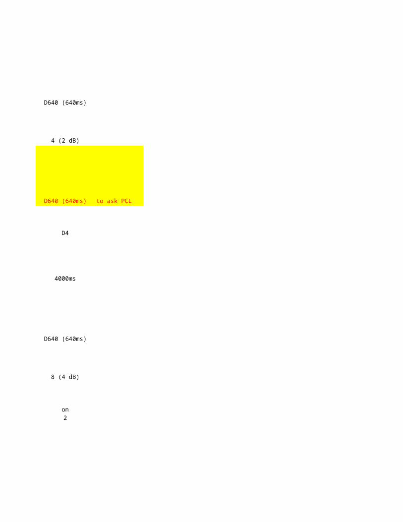
D640 (640ms)
4 (2 dB)
D640 (640ms) to ask PCL
D4
4000ms
D640 (640ms)
8 (4 dB)
on
2
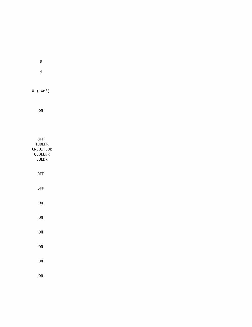
0
4
8 ( 4dB)
ON
OFF
OFF
OFF
ON
ON
ON
ON
ON
ON
IUBLDR CREDITLDR CODELDR
UULDR
Huawei Siemens
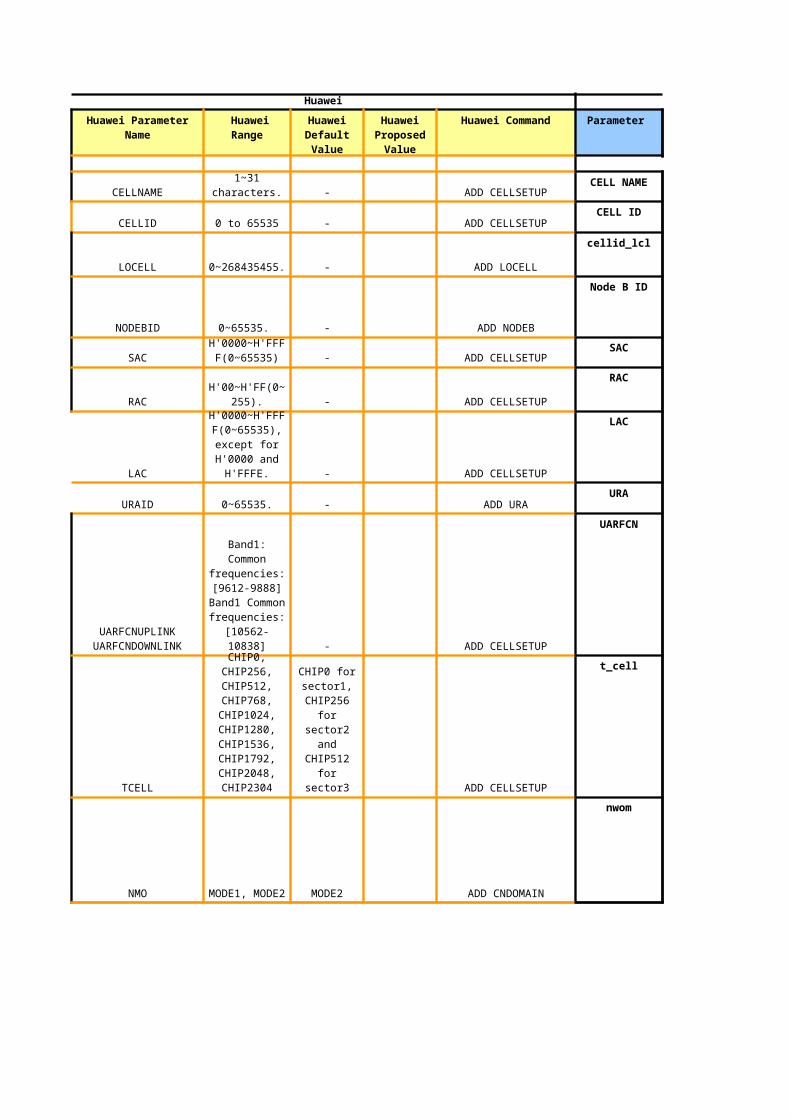
Huawei Parameter Name Huawei Range Huawei Command Parameter
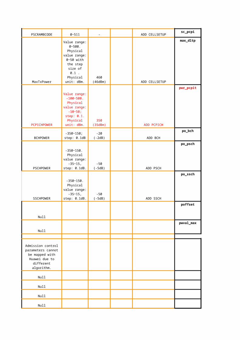
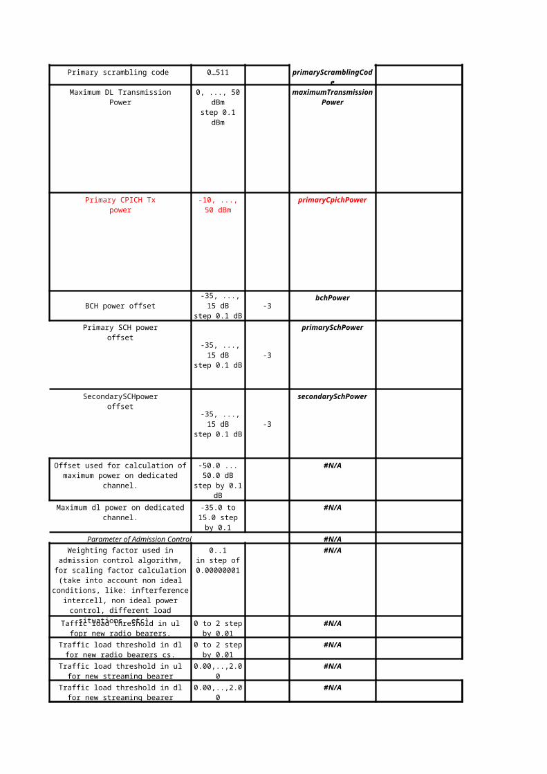
Offset used for calculation of maximum power on dedicated channel.
-50.0 ... 50.0 dB step by 0.1 dB
-35.0 to 15.0 step by 0.1
Weighting factor used in admission control algorithm, for scaling factor calculation (take
into account non ideal conditions, like: infterference intercell, non ideal power control, different load situations, etc).
0..1in step of
0.00000001
Taffic load threshold in ul fopr new radio bearers.
0 to 2 step by 0.01
Traffic load threshold in dl for new radio bearers cs.
0 to 2 step by 0.01
Traffic load threshold in ul for new streaming bearer
Traffic load threshold in dl for new streaming bearer
#N/A
#N/A
#N/A
#N/A
#N/A
#N/A
#N/A
#N/A
0 to 2 step 0.01 #N/A
0 to 2 step 0.01 #N/A
0 to 1 step 0.05 #N/A
0 to 1 step 0.05 #N/A
8, 16, 32 #N/A
Initial value for scaling factorin uL #N/A
Initial value for scaling factor in DL. #N/A
Initial value for thermal noise #N/A
#N/A
#N/A
#N/A
0 to 256 #N/A
8, 16, 32 #N/A
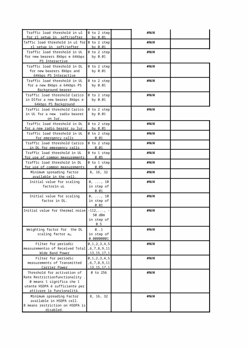
Traffic load threshold in ul for rl setup in soft/softer handover.
0 to 2 step by 0.01
Taffic load threshold in ul for rl setup in soft/softer handover.
0 to 2 step by 0.01
Traffic load threshold in UL for new bearers 8kbps e 64kbps PS Interactive
0 to 2 step by 0.01
Traffic load threshold in DL for new bearers 8kbps and 64kbps PS Interactive
0 to 2 step by 0.01
Traffic load threshold in UL for a new 8kbps e 64kbps PS Background bearer
0 to 2 step by 0.01
Traffic load threshold Carico in Dlfor a new bearer 8kbps e 64kbps PS Background
0 to 2 step by 0.01
Traffic load threshold Carico in UL for a new radio bearer on Iur.
0 to 2 step by 0.01
Traffic load threshold in DL for a new radio bearer su Iur.
0 to 2 step by 0.01
Traffic load threshold in UL for emergency calls
Traffic load threshold Carico in DL for emergency calls
Traffic load threshold in UL for use of common measurements
Traffic load threshold in DL for use of common measurements
Minimum spreading factor available in the cell.
0, ..., 10in step of 0.01
0, ..., 10in step of 0.01
-112,..., -50 dBm
in step of 0.5
Weighting factor for the DL scaling factor aDL 0..1in step of
0.00000001
Filter for periodic measurementso of Received Total Wide Band Power
0,1,2,3,4,5,6,7,8,9,11,13,15,17,1
9
Filter for periodic measurements of Transmitted Carrier Power
0,1,2,3,4,5,6,7,8,9,11,13,15,17,1
9
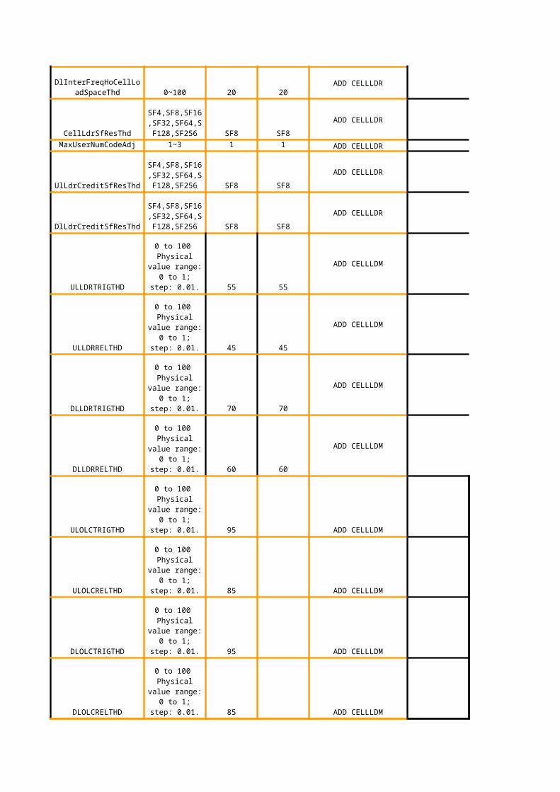
Threshold for activation of Rate Restrictionfunctionality .
0 means 1 significa che 1 utente HSDPA è sufficiente per attivare la funzionalità.
Minimum spreading Factor available in HSDPA cell.
8 means restriction on HSDPA is disabled.
0.00,..,1.00 #N/A
#N/A
#N/A
#N/A
#N/A
#N/A
pwrAdm
#N/A - same as line 83
Threshold of adjourning for the scaling factors.
Cell parameter that defines the absolute admission limit for downlink power utilization. Applicable to
(guaranteed, non-handover) and (non-
guaranteed, handover) admission requests. It is
relative to the min(maximumTransmissio
nPower, maxDlPowerCapability), it
is expressed as a percentage and that is a
precentage of min(maximumTransmissio
nPower, maxDlPowerCapability).
beMarginDlPwr
#N/A
#N/A
#N/A
#N/A
#N/A
#N/A
pwrAdmOffsetor
pwrAdm
pwrAdmOffset for G-HOpwrAdm for NG-HO
#N/ApwrAdmOffset
#N/AmaxTxPowerUl
#N/AmaxTxPowerUl
#N/AmaxTxPowerUl
#N/AmaxTxPowerUl
K87
Author: admission requests can be granted when the resource usage exceeds the pwrAdm - beMarginDlPwr level if it is possible to free resources by downswitching a non-guaranteed user with a lower spreading factor than the spreading factor being requested in the admission request (Enhanced soft congestion control), otherwise they are blocked when the resource usage exceeds the pwrAdm - beMarginDlPwr level.
K89
Author: NG-HO: (Non-guaranteed, handover) admission requests can be granted when the resource usage exceeds the pwrAdm level if it is possible to free resources by downswitching a non-guaranteed user with a lower spreading factor than the spreading factor being requested in the admission request (Enhanced soft congestion control), otherwise they are blocked when the resource usage exceeds the pwrAdm level. G-HO: admission requests can be granted when the resource usage exceeds the pwrAdm + pwrAdmOffset level if it is possible to free resources by downswitching a non-guaranteed user (Enhanced soft congestion control), otherwise they are blocked when the resource usage exceeds the pwrAdm+ pwrAdmOffset level.
#N/A
hsdpaUsersAdm
#N/A
#N/A
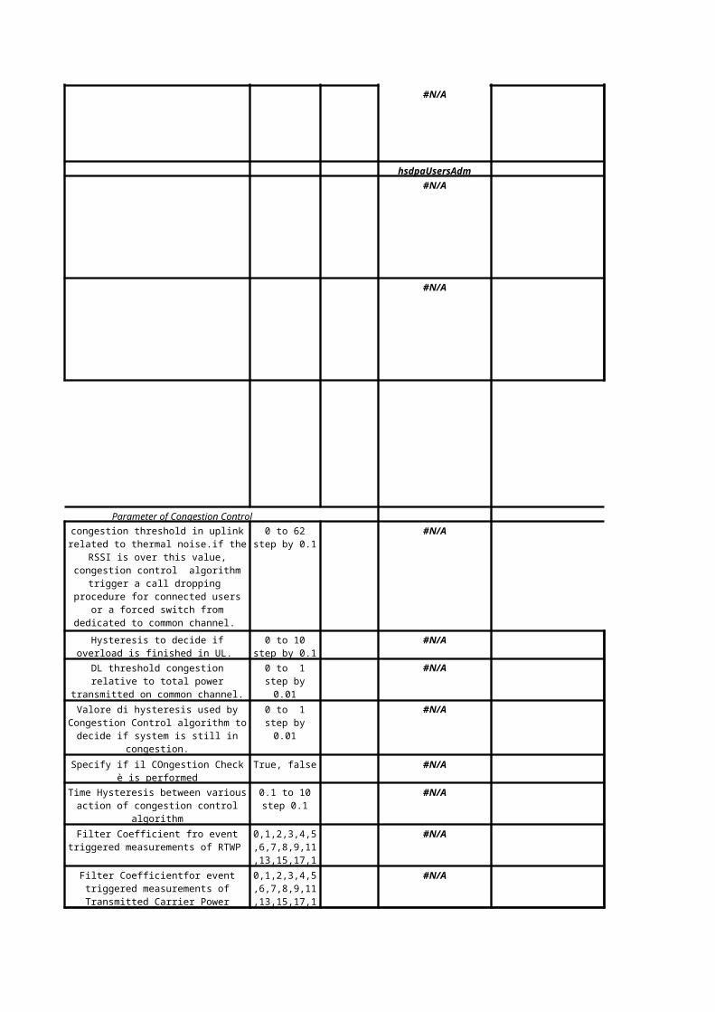
Parameter of Congestion Control
#N/A
#N/A
#N/A
#N/A
True, false #N/A
#N/A
#N/A
#N/A
congestion threshold in uplink related to thermal noise.if the RSSI is over this value, congestion control algorithm trigger a call
dropping procedure for connected users or a forced switch from dedicated to common
channel.
0 to 62 step by 0.1
Hysteresis to decide if overload is finished in UL.
0 to 10 step by 0.1
DL threshold congestion relative to total power transmitted on common channel.
0 to 1 step by 0.01
Valore di hysteresis used by Congestion Control algorithm to decide if system is still in
congestion.
0 to 1 step by 0.01
Specify if il COngestion Check è is performed
Time Hysteresis between various action of congestion control algorithm
0.1 to 10 step 0.1
Filter Coefficient fro event triggered measurements of RTWP
0,1,2,3,4,5,6,7,8,9,11,13,15,17,1
9
Filter Coefficientfor event triggered measurements of Transmitted Carrier Power
0,1,2,3,4,5,6,7,8,9,11,13,15,17,1
9
#N/A
#N/A
0 to 10 #N/A
#N/A
#N/A
#N/A
During this time Congestion Control algorithm verify if congestion state is solved
or not, checking uplink ionterference.
0.01 to 3600 (0.01 to 60 by step 0.01 sec).
During this time Congestion Control algorithm verify if congestion state is solved or not, checking total transmitted power on
common channels in DL.
0.01 to 3600 (0.01 to 60 by step 0.01 sec).
Number of bearers switched to common channel (or released) for each report.
Decide if enabling possibility of release connections in case of overload.
ena: enabledis: disable
Enable the Transport/Physical Channel Reconfiguration procedure.
ena: enabledis: disable
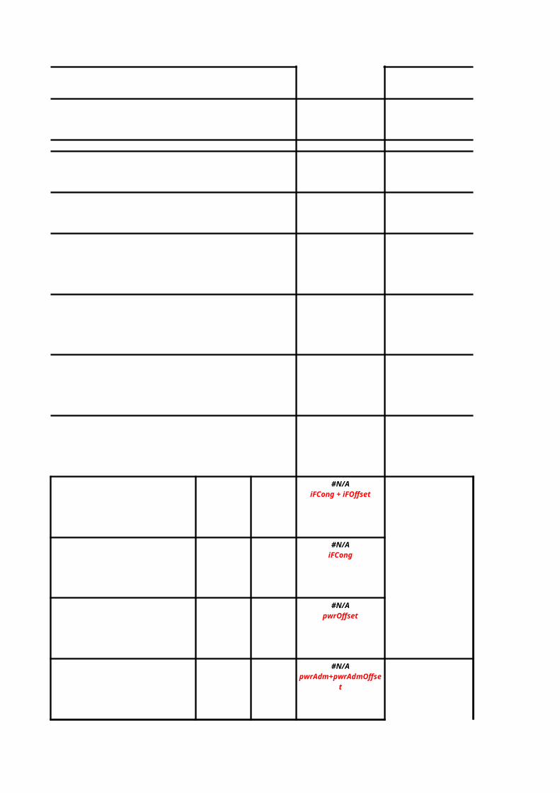
#N/AiFCong + iFOffset
#N/AiFCong
#N/ApwrOffset
#N/ApwrAdm+pwrAdmOffset
#N/A
#N/A
#N/A
#N/A
#N/A
#N/A
#N/A
#N/A
#N/A
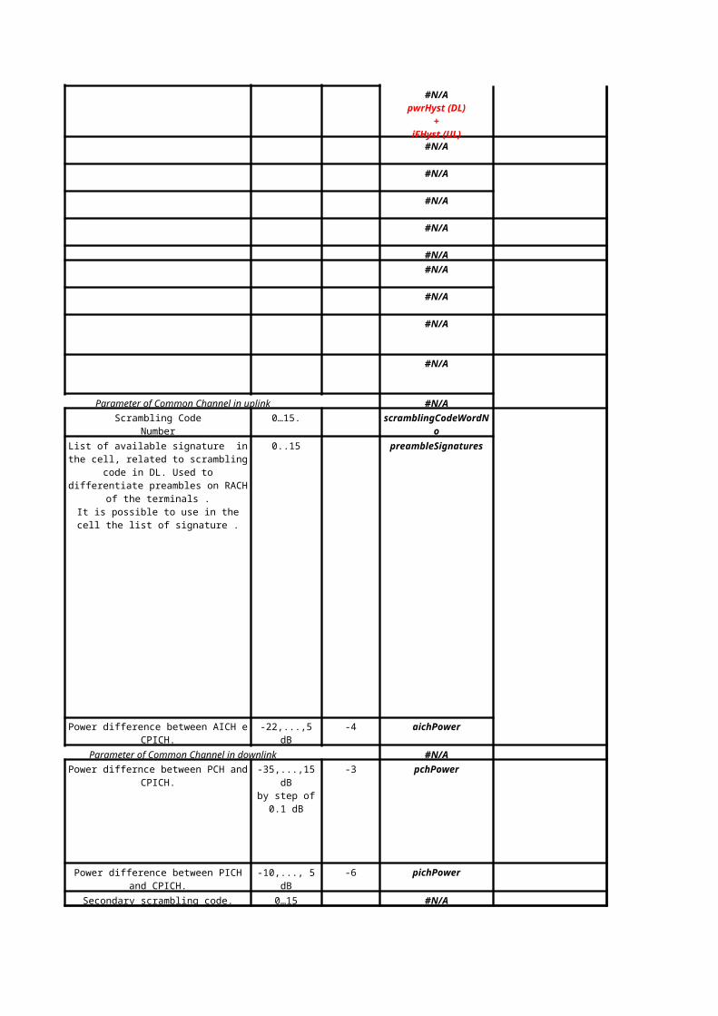
Parameter of Common Channel in uplink #N/A
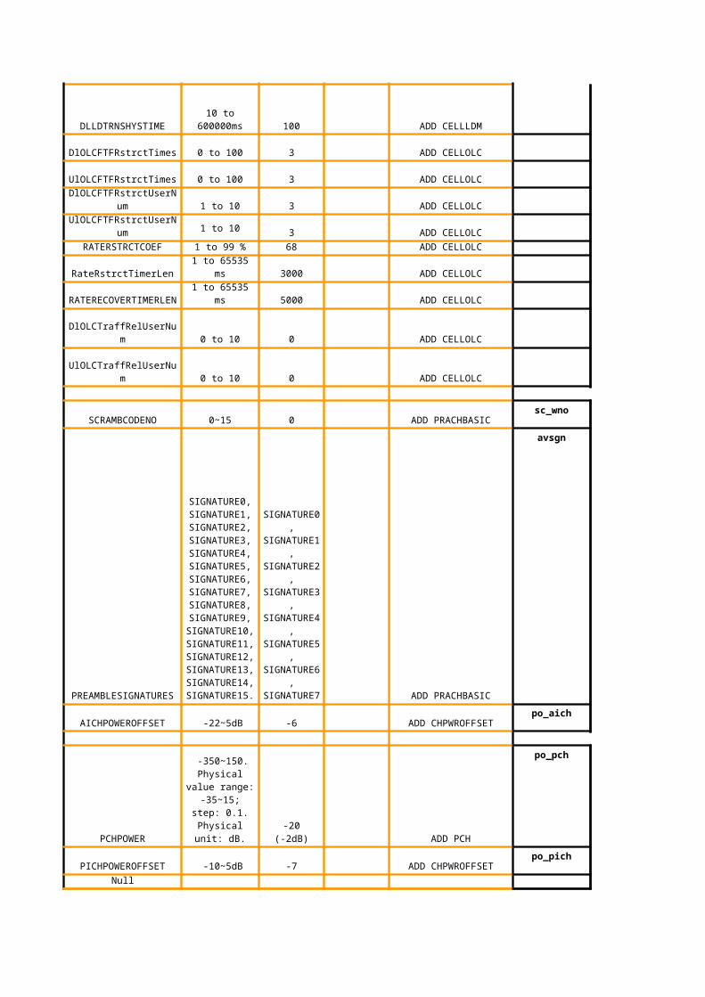
0…15. scramblingCodeWordNo
0..15 preambleSignatures
Power difference between AICH e CPICH. -22,...,5 dB -4 aichPower
Parameter of Common Channel in downlink #N/A
Power differnce between PCH and CPICH. -3 pchPower
Power difference between PICH and CPICH. -10,..., 5 dB -6 pichPower
Secondary scrambling code. 0…15 #N/A
#N/ApwrHyst (DL)
+iFHyst (UL)
Scrambling CodeNumber
List of available signature in the cell, related to scrambling code in DL. Used to
differentiate preambles on RACH of the terminals .
It is possible to use in the cell the list of signature .
-35,...,15 dBby step of 0.1
dB
J138
Author: 1. AC - Block all new request for DL cong, Block non-HO for UL cong 2. DL cong - release DL ASE by reduce PS rate or release bearer (to common ch)
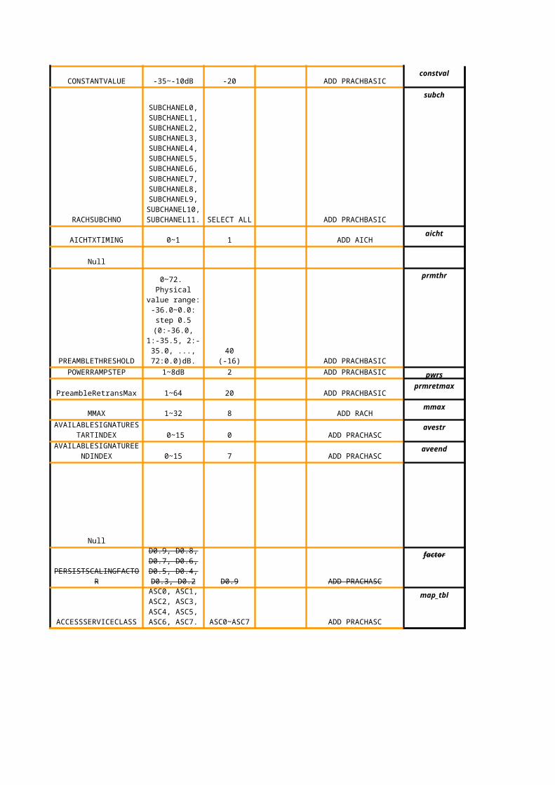
Constant for calculation of PRACH. -35 to -10 [dB] constantValueCprach
Number of sub channel available on RACH 0 to 11 subChannelNo
AICH transmission Timing 0 to 1 aichTransmissionTiming
Number of codes of channalization for AICH 0 to 255 #N/A
Threshold for preamble definition #N/A
Step for raising of power 1 to 8 powerOffsetP0
Max number of preambols. 1 to 64 preambleRetransMax
Max number of cycles . 1 to 32 maxPreambleCycle
Starting index for Available Signature 0 to 15 #N/A
End index for Available Signature 0 to 15 #N/A
Parameter for UE to decide access slot #N/A
scaling factor persistence. #N/A
Ac to ASC mapping table 0 to 7 #N/A
-36.0 to 0.0 step 0.5
D1: b30 to 1D2: b20 to 1D3: b10 to 1D4: b00 to 1
0.2 to 0.9 step 0.1
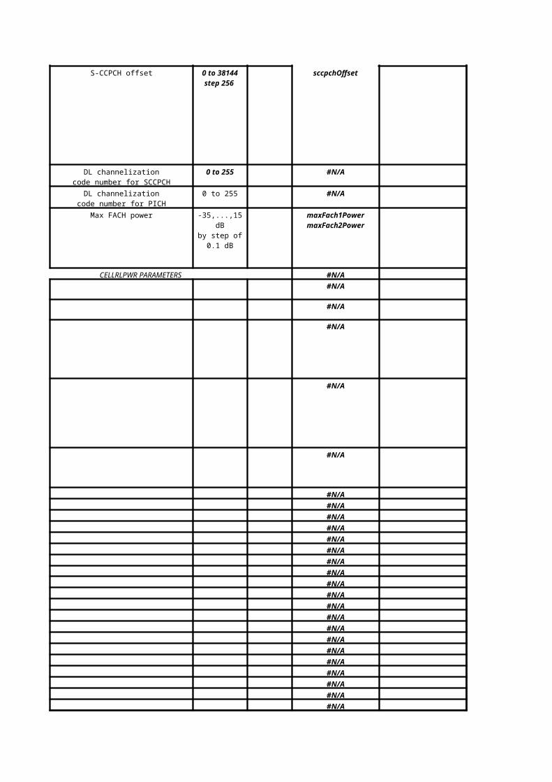
S-CCPCH offset sccpchOffset
0 to 255 #N/A
0 to 255 #N/A
Max FACH power
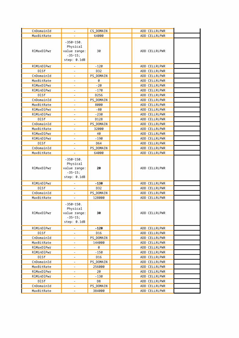
CELLRLPWR PARAMETERS #N/A
#N/A
#N/A
#N/A
#N/A
#N/A
#N/A
#N/A
#N/A
#N/A
#N/A
#N/A
#N/A
#N/A
#N/A
#N/A
#N/A
#N/A
#N/A
#N/A
#N/A
#N/A
#N/A
#N/A
#N/A
#N/A
0 to 38144 step 256
DL channelizationcode number for SCCPCH
DL channelizationcode number for PICH
-35,...,15 dBby step of 0.1
dB
maxFach1PowermaxFach2Power
#N/A
#N/A
#N/A
#N/A
#N/A
#N/A
#N/A
#N/A
#N/A
#N/A
#N/A
#N/A
#N/A
#N/A
#N/A
#N/A
#N/A
#N/A
#N/A
#N/A
#N/A
#N/A
#N/A
#N/A
#N/A
#N/A
#N/A
#N/A
#N/A
#N/A
#N/A
#N/A
#N/A
#N/A
#N/A
#N/A
#N/A
#N/A
#N/A
#N/A
#N/A
#N/A
#N/A
#N/A
#N/A
Add Typical RAB OLPC Parameters #N/A
#N/A
#N/A
Ericsson Maxis
Range E/// Live Network Value Maxis Optimized Value
#N/A
#N/A
#N/A
#N/A
#N/A
Gs interface between SGSN & MSC
From Radio Network Design
From Radio Network Design
From Radio Network Design
From Radio Network Design
From Radio Network Design
From Radio Network Design
From Radio Network Design
1
Maxis Optimized Value
#N/A
#N/A
#N/A
#N/A
#N/A
#N/A
#N/A
#N/A
no relation with T315!!!relation with T313
#N/A
#N/A
#N/A
#N/A
cell updates for CS ( diff rb timer)
49=294min
M16
Author: optimised value
#N/A
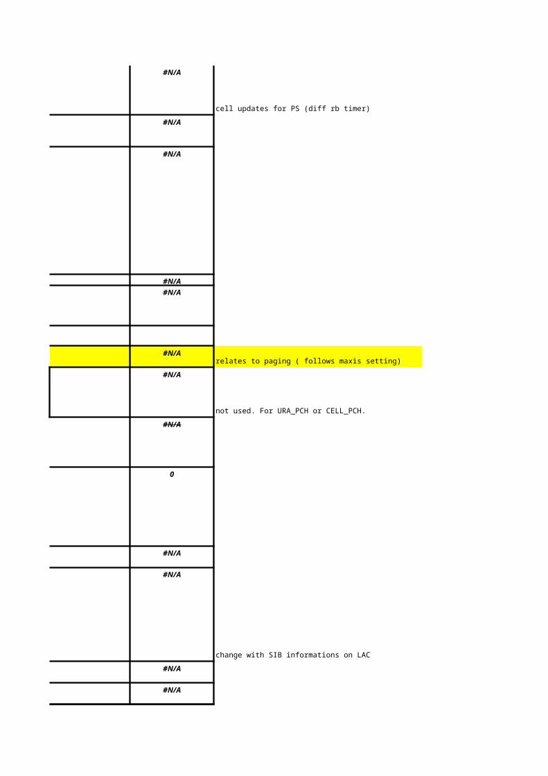
cell updates for PS (diff rb timer)
#N/A
#N/A
#N/A
#N/A
#N/Arelates to paging ( follows maxis setting)
#N/A
not used. For URA_PCH or CELL_PCH.
#N/A
0
#N/A
#N/A
change with SIB informations on LAC
#N/A
#N/A
-31
HW default
-18
HW default
-35
HW default
#N/A
#N/A
#N/A
#N/A
#N/A
#N/A
#N/A
#N/A
From Radio Network Design
maxDlPowerCapability - 4 (for macro site)
maxDlPowerCapability - 8 (for inbuilding
system)
From Radio Network Design and Tuning
#N/A
#N/A
#N/A
#N/A
#N/A
#N/A
#N/A
#N/A
#N/A
#N/A
#N/A
#N/A
#N/A
#N/A
#N/A
#N/A
#N/A
#N/A
#N/A
#N/A
#N/A
#N/A
#N/A
#N/A What is this?
#N/A By default HW not using
By default HW not using
#N/A By default HW not using
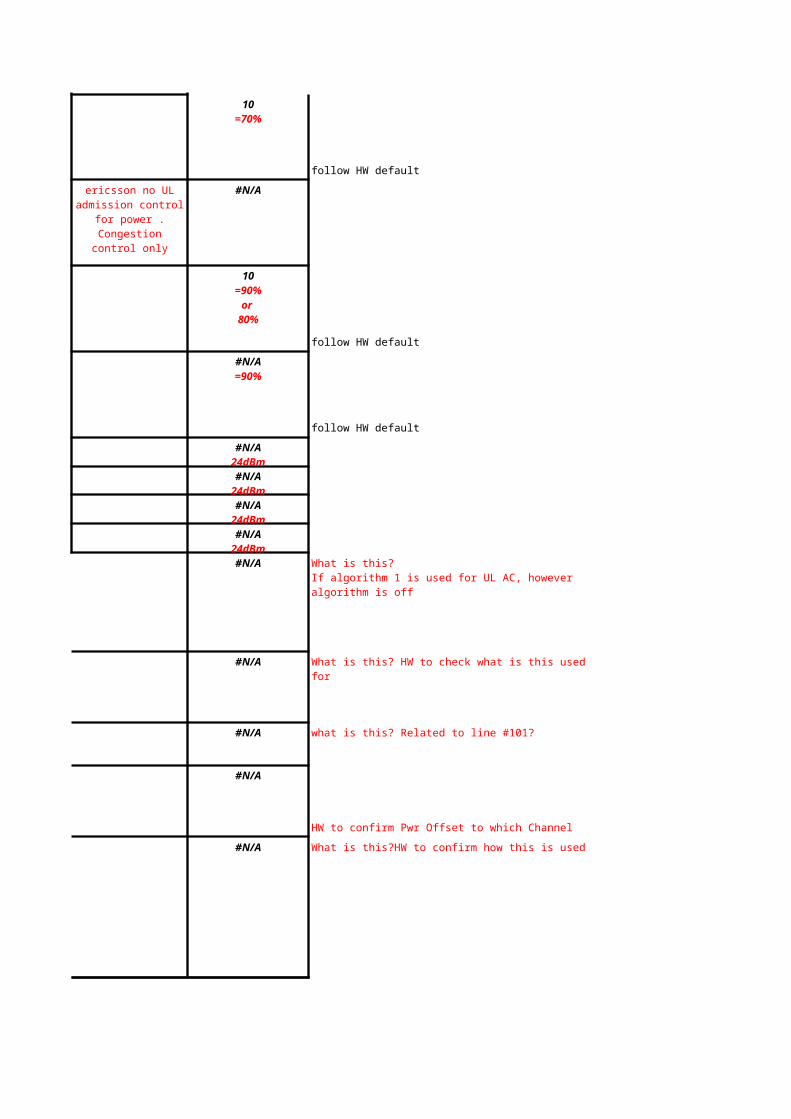
80%
follow HW default
#N/A
follow HW default
ericsson no UL admission control for power . Congestion
control only
ericsson no UL admission control for power . Congestion
control only
#N/A
ericsson no UL admission control for power . Congestion
control only
follow HW default
#N/A
follow HW default
follow HW default
#N/A
#N/A What is this? HW to check what is this used for
#N/A what is this? Related to line #101?
#N/A
HW to confirm Pwr Offset to which Channel
#N/A What is this?HW to confirm how this is used
10=70%
ericsson no UL admission control for power . Congestion
control only
10=90%
or 80%
#N/A=90%
#N/A24dBm
#N/A24dBm
#N/A24dBm
#N/A24dBm
What is this?If algorithm 1 is used for UL AC, however algorithm is off
M90
Author: Pwr Adm for HS (both HO and Non-HO)
#N/A What is this?HW to confirm how this is used
16
#N/A What is this?
#N/A
can select multiple at a time when turn on.
#N/A
#N/A
#N/A
#N/A
#N/A
#N/A
#N/A
#N/A
What is this?1st: Current + New power3rd: Current power
#N/A
#N/A
#N/A
#N/A
#N/A
Follow HW default
Follow HW default
Follow HW default ( 1 user at at time)
#N/A Follow HW default ( 1 user at at time)
Follow HW default ( judging the load for the target cell. It has to be more than 20% available resource ).
HW default
Not used.
HW default
HW default
HW default- seeing from source cell.
HW default- seeing from source cell.
HW default- seeing from source cell.
HW default- seeing from source cell.
HW default
HW default
HW default
HW default
Follow HW default ( judging the load for the target cell. It has to be more than 20% available resource ).
#N/A-49.9dBm
#N/A-49.9dBm
#N/A95%
#N/A90%
M133
Author: with timer
M134
Author: with timer
M136
Author: with timer
Huawei is for DL only?
#N/AHW defualt ( 3 times)
#N/AHW defualt ( 3 times)
#N/AHW default ( 3 users)
#N/AHW default ( 3 users)
#N/A HW default ( what kind of TF it is used)
#N/AHW default
#N/AHW default
#N/A
HW default
#N/A
HW default
#N/A
0
65535
-6
#N/A
-4
HW default. Tested in other network.
-7HW default.
#N/A
#N/A300ms
+60s
-27HW default.
4095
HW default.
4HW default: 1 = 1280 chips
#N/A
#N/A
HW default
3 HW default
8HW default- 20 times
4HW default
#N/AHW default
#N/AHW default
#N/A
#N/A
Not used.
#N/A
access priority for RACH.
20
#N/A
#N/A
#N/A
#N/A
#N/A
#N/A
#N/A
#N/A
#N/A
#N/A
#N/A
#N/A
#N/A
#N/A
#N/A
#N/A
#N/A
#N/A
#N/A
#N/A
#N/A
#N/A
#N/A
#N/A
#N/A
#N/A
#N/A
#N/A
1815
#N/A
#N/A
#N/A
#N/A
#N/A
#N/A
#N/A
#N/A
#N/A
#N/A
#N/A
#N/A
#N/A
#N/A
#N/A
#N/A
#N/A
#N/A
#N/A
#N/A
#N/A
#N/A
#N/A
#N/A
#N/A
#N/A
#N/A
#N/A
#N/A
#N/A
#N/A
#N/A
#N/A
#N/A
#N/A
#N/A
#N/A
#N/A
#N/A
#N/A
#N/A
#N/A
#N/A
#N/A
#N/A
#N/A
#N/A
for video call
#N/A
for voice call
HW to check how Credit resource limit works at cell level
If new request used above SF32 (>64kbps), trigger AC due to code
How HSDPA is affected by LDR??? Since LDR is triggered by R99 resources
Maxis
Discuss Final Agreed Value
-
-
-
-
-
-
-
-
-
MODE2
CHIP0 for sector1, CHIP256 for sector2
and CHIP512 for sector3
ALLOWED
294 min
6
3
1
3
3
5
D1(1)
D2000(2000ms)
D40(40ms)
D50(50)
D1(1)
D2000(2000ms)
D20(20s)
3
D30 (30 min)
7
NA
0
NA
1~256
NA
NA
D30(30s)
D2000(2000ms)
D30(30s)
D30(30s)
-
-
NA
NA
NA
NA
NA
NA
NA
HW to get back to us for macro & IBC
-20(-2dB)
-50(-5dB)
-50(-5dB)
NA
NA
NA
NA
NA
NA
NA
NA
NA
NA
NA
NA
NA
NA
NA
NA
NA
NA
NA
NA
NA
NA
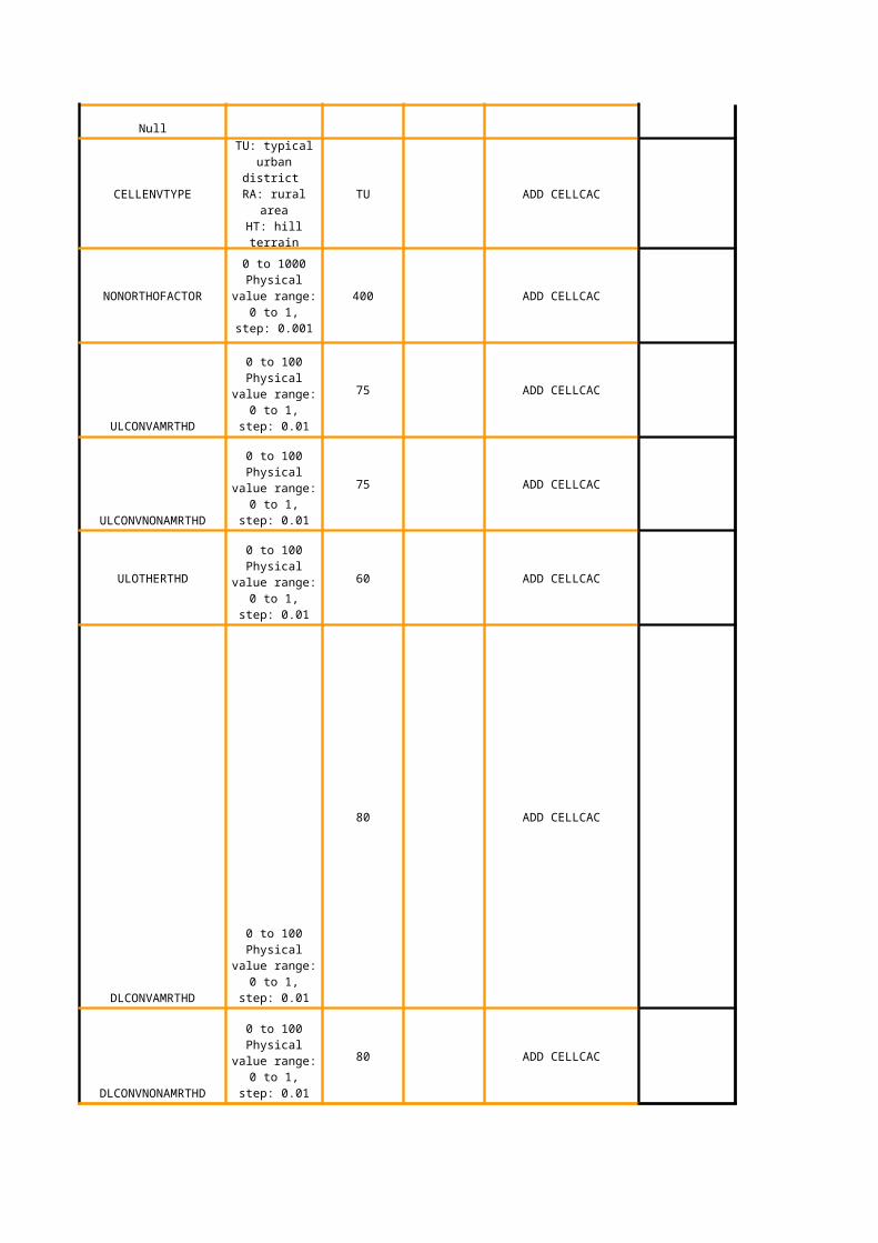
TU
用于载波发射功率预测值计算 400
75
75
60
80%
80%
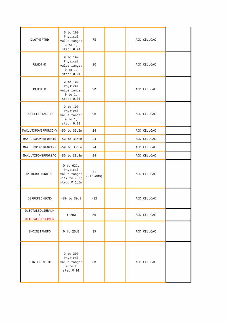
P81
tanbk: calc other channel interference (for load calc)
75%
Not used (80)
85%
90%
24
24
24
24
71 (-105)
-13
Not used (80)
15
60
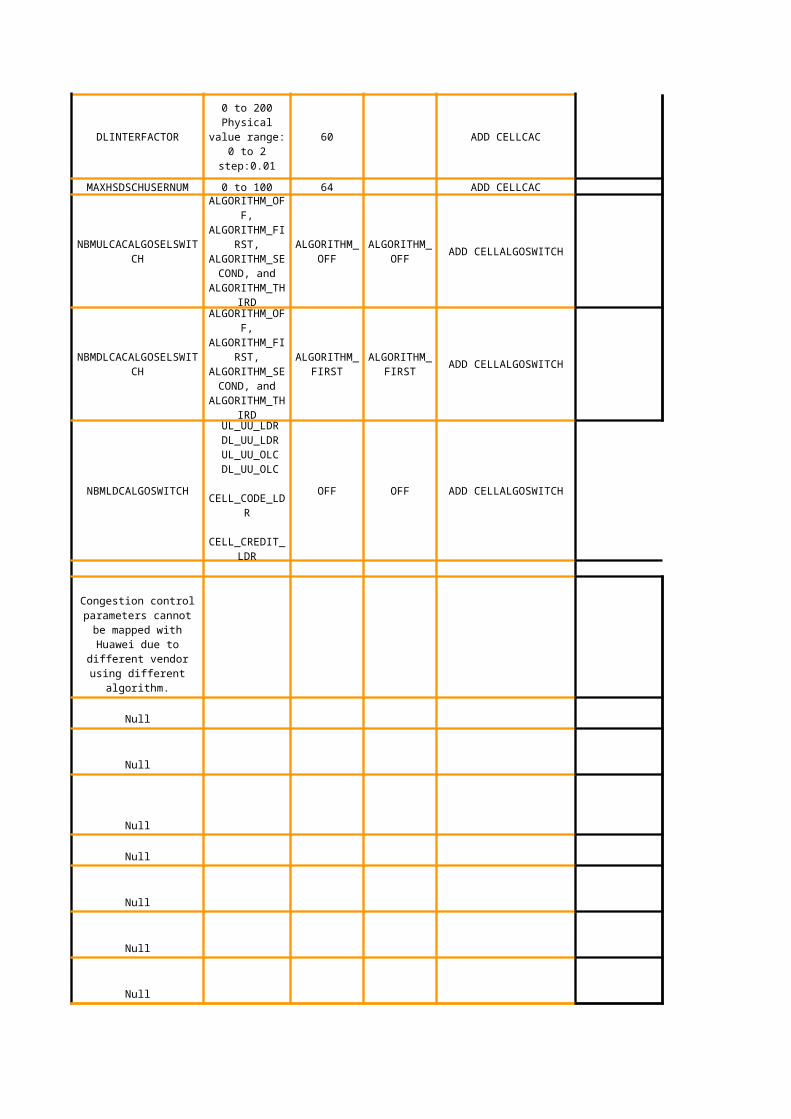
Direction: DL. To calculate the initial power for UE when rrc con. Request ( follow HW default)
initial power offset to new RL. Follows with inner loop power control adjustment. Follow HW default.
HW current RAN is using ULINTERFACTOR only. NOT applicable for DLINETERFACTOR. It is used to calculate the load factor denotes in the system ,ULINTERFACTOR= 1 - Pn/ RTWP. Follow HW default.
O96
Author: tftan
Not used in current RAN NA (60)
64
Algorithm Off
ALGORITHM_FIRST
OFF
NA
NA
NA
NA
NA
NA
NA
NA
NA
NA
NA
NA
NA
1
1
20
Default LDR is off. Will turn on for congested cells only.
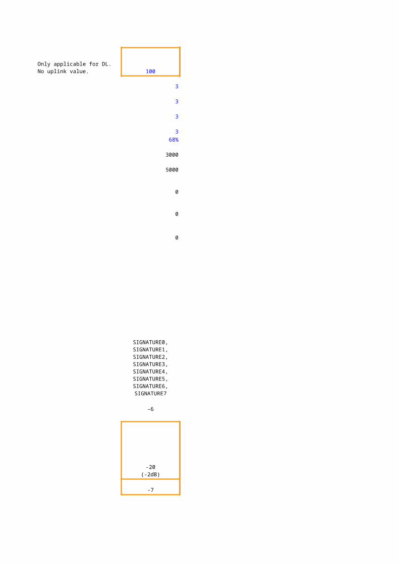
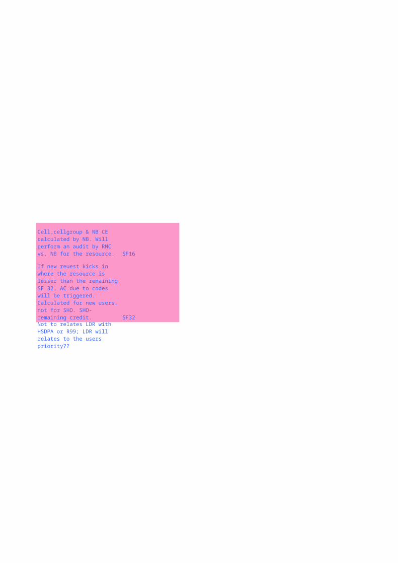
Cell,cellgroup & NB CE calculated by NB. Will perform an audit by RNC vs. NB for the resource.
If new reuest kicks in where the resource is lesser than the remaining SF 32, AC due to codes will be triggered. Calculated for new users, not for SHO. SHO- remaining credit.
Not to relates LDR with HSDPA or R99; LDR will relates to the users priority??
document.xls 文档密级
04/17/2023 华为机密,未经许可不得扩散 第127页,共163页
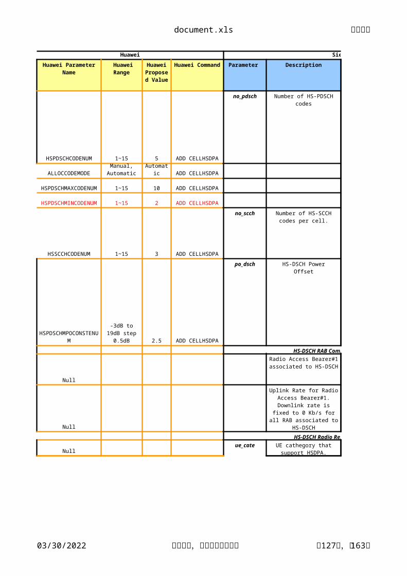
Huawei Siemens
Huawei Parameter Name Huawei Range Huawei Command Parameter Description
HSPDSCHCODENUM 1~15 5 ADD CELLHSDPA
no_pdsch
ALLOCCODEMODE ADD CELLHSDPA
1~15 10 ADD CELLHSDPA
1~15 2 ADD CELLHSDPA
HSSCCHCODENUM 1~15 3 ADD CELLHSDPA
no_scch
2.5 ADD CELLHSDPA
po_dsch
HS-DSCH RAB Combination Parameters
Null
Null
HS-DSCH Radio Resource Management
Nullue_cate
Huawei Proposed
Value
Number of HS-PDSCHcodes
Manual, Automatic
Automatic
HSPDSCHMAXCODENUM
HSPDSCHMINCODENUM
Number of HS-SCCHcodes per cell.
HSPDSCHMPOCONSTENUM
-3dB to 19dB step 0.5dB
HS-DSCH PowerOffset
Radio Access Bearer#1 associated to HS-DSCH
Uplink Rate for Radio Access Bearer#1.
Downlink rate is fixed to 0 Kb/s for all RAB associated to HS-
DSCH
UE cathegory that support HSDPA.
document.xls 文档密级
04/17/2023 华为机密,未经许可不得扩散 第128页,共163页
CQIFBCK SET HSDPCCH
cqi_cyclek
CQIREF 1 to 4 1 SET HSDPCCH
cqi_rep
ACKNACKREFFORSHO 1 to 4 1 SET HSDPCCH
ack_nack_rep
SET HSDPCCH
ack_po
SET HSDPCCH
nack_po
HSSCCHPOFORSF128 SET HSSCCH
hsscch_po
SCCHPWRCM CQI,FIXED CQI
D0, D2, D4, D8, D10, D20,
D40, D80, D160ms
D2(2ms)
Period of repetition of a CQI measurement report
Number of repetitions of a CQI report. Not necessary
if CQI Feedback Cycle k = 0.
Number of repetitions of ACK/NACK reports
ACKPO1ACKPO2ACKPO3
PO_5/15, PO_6/15, PO_8/15, PO_9/15,
PO_12/15, PO_15/15, PO_19/15, PO_24/15, PO_30/15
PO_24/15PO_12/15PO_9/15
Power offset used in the UL between the HSDPCCHslot carrying HARQ ACK
informationand the associated DPCCH
NACKPO1NACKPO2NACKPO3
PO_5/15, PO_6/15, PO_8/15, PO_9/15,
PO_12/15, PO_15/15, PO_19/15, PO_24/15, PO_30/15
PO_24/15PO_12/15PO_9/15
Power offset used in the UL between the HSDPCCH
slot carrying HARQ NACK information
and the associated DPCCH
Value range: -128 to 127
Physical value range: -32 to 31.75, step:
0.25dB33(8.25d
B)
Power offset of HS-SCCH relative to the pilot
bits on the DL DPCCH
document.xls 文档密级
04/17/2023 华为机密,未经许可不得扩散 第129页,共163页
SCCHPWR 20 (-5 dB)
CQIPO PO_24/15 ADD CELLHSDPA
cqi_po
HSDPA parameters in NodeB
CELLID 0 to 65535 - ADD CELLHSDPA
cellid Cell ID.
Nullnodebid -
ACT CELLHSDPA - - ACT CELLHSDPAhsdpaCapable
Null
Define modulation HSDPA
SM EPF SET MACHSPARA
0~80 (-10 ~10 dB step
0.25 dB)
PO_5/15, PO_6/15, PO_8/15, PO_9/15,
PO_12/15, PO_15/15, PO_19/15, PO_24/15, PO_30/15
Power offset used in the UL between the HSDPCCH
slots carrying CQI information and the
associated DPCCH
Show if HSDPA is enabled in the cell
PF(PF algorithm),RR(Round
Robin),MAXCI(Max
C/Ialgorithm)
scheduler algorithm for HSDPA.
document.xls 文档密级
04/17/2023 华为机密,未经许可不得扩散 第130页,共163页
Siemens Ericsson
Range Live Network Value Parameter Description Range
maximum supportable #N/A 5
#N/A #N/A
#N/A #N/A
#N/A #N/A
3 #N/A #N/A
3 #N/A #N/A
HS-DSCH RAB Combination Parameters #N/A #N/A
#N/A #N/A
64 kbps #N/A #N/A
HS-DSCH Radio Resource Management #N/A #N/A
1 to 12 #N/A #N/A
E/// Live Network
Value
no_pdsch=DD1 to 15
numHsPdschCodes
no_scch=D1 to 4
po_dsch=DD.D-6 to 13 step 0.5
rab1=CCCCpsib: PS
Interactive/Background
ul_rate1=CCCCCCC64kbps: 64 Kb/s
384kbps: 384 Kb/s
ue_cate=DD1 to 64
document.xls 文档密级
04/17/2023 华为机密,未经许可不得扩散 第131页,共163页
4 #N/A #N/A
1 #N/A #N/A
1 #N/A #N/A
5 #N/A #N/A
5 #N/A #N/A
3 #N/A #N/A
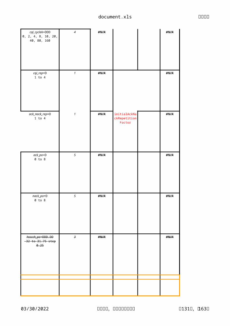
cqi_cyclek=DDD0, 2, 4, 8, 10, 20, 40, 80,
160
cqi_rep=D1 to 4
ack_nack_rep=D1 to 4
initialAckNackRepetitionFactor
ack_po=D0 to 8
nack_po=D0 to 8
hsscch_po=DDD.DD-32 to 31.75 step 0.25
document.xls 文档密级
04/17/2023 华为机密,未经许可不得扩散 第132页,共163页
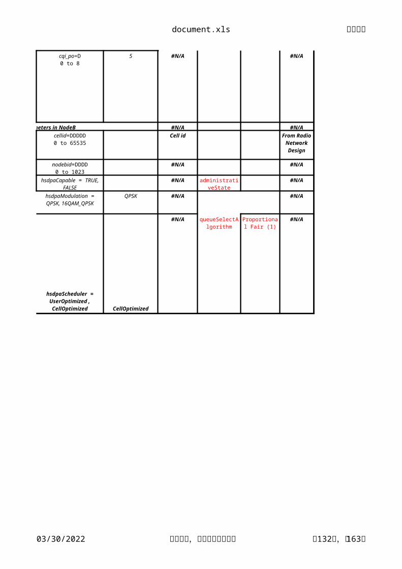
5 #N/A #N/A
HSDPA parameters in NodeB #N/A #N/A
Cell id
#N/A #N/A
#N/A #N/A
QPSK #N/A #N/A
CellOptimized
#N/A #N/A
cqi_po=D0 to 8
cellid=DDDDD0 to 65535
From Radio Network Design
nodebid=DDDD0 to 1023
hsdpaCapable = TRUE, FALSE
administrativeState
hsdpaModulation = QPSK, 16QAM_QPSK
hsdpaScheduler = UserOptimized, CellOptimized
queueSelectAlgorithm
Proportional Fair (1)
document.xls 文档密级
04/17/2023 华为机密,未经许可不得扩散 第133页,共163页
Maxis
Maxis Optimized Value Discuss
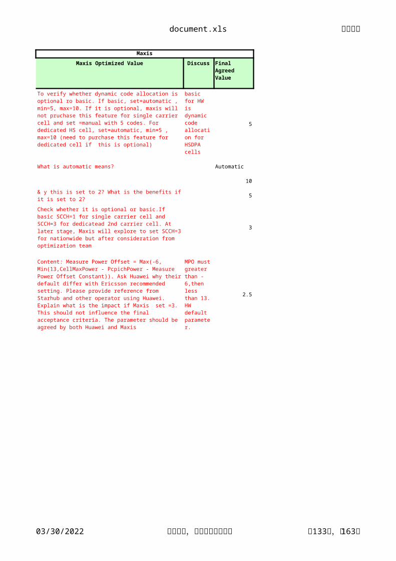
5
What is automatic means? Automatic
10
& y this is set to 2? What is the benefits if it is set to 2? 5
3
2.5
Final Agreed Value
To verify whether dynamic code allocation is optional ro basic. If basic, set=automatic , min=5, max=10. If it is optional, maxis will not pruchase this feature for single carrier cell and set =manual with 5 codes. For dedicated HS cell, set=automatic, min=5 , max=10 (need to purchase this feature for dedicated cell if this is optional)
basic for HW is dynamic code allocation for HSDPA cells
Check whether it is optional or basic.If basic SCCH=1 for single carrier cell and SCCH=3 for dedicatead 2nd carrier cell. At later stage, Maxis will explore to set SCCH=3 for nationwide but after consideration from optimization team
Content: Measure Power Offset = Max(-6, Min(13,CellMaxPower - PcpichPower - Measure Power Offset Constant)). Ask Huawei why their default differ with Ericsson recommended setting. Please provide reference from Starhub and other operator using Huawei. Explain what is the impact if Maxis set =3. This should not influence the final acceptance criteria. The parameter should be agreed by both Huawei and Maxis
MPO must greater than -6,then less than 13. HW default parameter.
document.xls 文档密级
04/17/2023 华为机密,未经许可不得扩散 第134页,共163页
2ms
1
1
Using CQI b NA
CQI
Ask Huawei why their default differ with Ericsson recommended setting. Please provide reference from Starhub and other operator using Huawei. Explain what is the impact if Maxis set accordance to our current vaule.This should not influence the final acceptance criteria. The parameter should be agreed by both Huawei and Maxis
Ask Huawei why their default differ with Ericsson recommended setting. Please provide reference from Starhub and other operator using Huawei. Explain what is the impact if Maxis set accordance to our current vaule.This should not influence the final acceptance criteria. The parameter should be agreed by both Huawei and Maxis
Ask Huawei why their default differ with Ericsson recommended setting. Please provide reference from Starhub and other operator using Huawei. Explain what is the impact if Maxis set accordance to our current vaule.This should not influence the final acceptance criteria. The parameter should be agreed by both Huawei and Maxis
Ask Huawei why their default differ with Ericsson recommended setting. Please provide reference from Starhub and other operator using Huawei. Explain what is the impact if Maxis set accordance to our current vaule.This should not influence the final acceptance criteria. The parameter should be agreed by both Huawei and Maxis PO_24/15
PO_12/15PO_9/15
Ask Huawei why their default differ with Ericsson recommended setting. Please provide reference from Starhub and other operator using Huawei. Explain what is the impact if Maxis set accordance to our current vaule.This should not influence the final acceptance criteria. The parameter should be agreed by both Huawei and Maxis
document.xls 文档密级
04/17/2023 华为机密,未经许可不得扩散 第135页,共163页
Using CQI b NA
PO_24/15
-
-
EPF
to ask PCL
Ask Huawei why their default differ with Ericsson recommended setting. Please provide reference from Starhub and other operator using Huawei. Explain what is the impact if Maxis set accordance to our current vaule.This should not influence the final acceptance criteria. The parameter should be agreed by both Huawei and Maxis
EPF: The SPI of user, the GBR configured, the current service rate and CQI are all taken into account. This method is relatively prior to the above ones on the aspect of fairness for users and system capacity. PF: the current available data transmission rate and the history rate are both in consideration. Thus, users with nice CQI and users with a long waiting history will be taken into account at the same time. This is a compromise of cell throughput priority and user fairness priority methods.
document.xls 文档密级
04/17/2023 华为机密,未经许可不得扩散 第136页,共163页
Huawei Siemens Huawei Range Parameter
CELLID 0 to 65535 -
RNCID 0 to 4095 -
Rncid_u
MCC 000~999. - ADD NRNCmcc
MNC 00~99 or 000~999 - ADD NRNC
mnc
NCELLID 0 to 65535 -
cellid_u
Null
acii
0
cio
-50 to +50dB 0
qoffset1
-50 to +50dB 0
qoffset2
Huawei Parameter Name
Huawei Proposed Value
Huawei Command
ADD INTRAFREQNC
ELL
CellId (source cell)
ADD INTRAFREQNC
ELL
ADD INTRAFREQNC
ELL
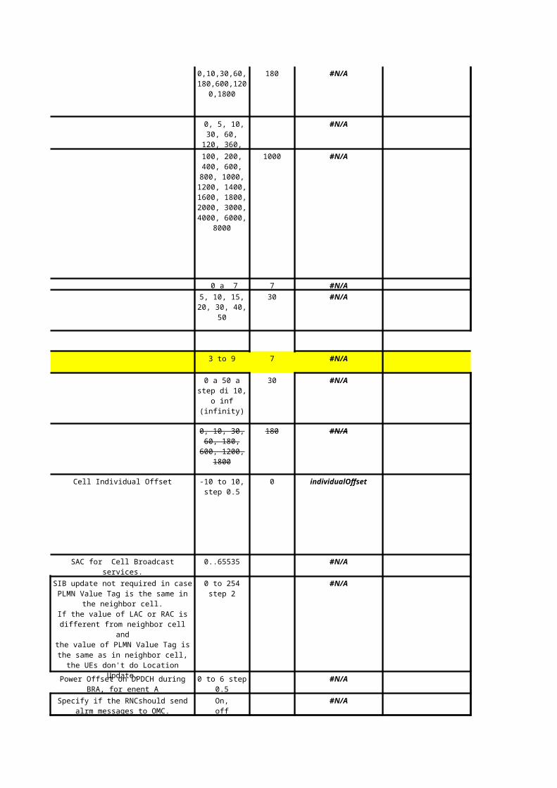
CELLINDIVIDALOFFSET
-20 to +20 Physical value range: -10 to
+10, step: 0.5 Physical unit: dB
ADD INTRAFREQNC
ELL
IDLEQOFFSET1SNCONNQOFFSET1SN
ADD INTRAFREQNC
ELL
IDLEQOFFSET2SNCONNQOFFSET2SN
ADD INTRAFREQNC
ELL
document.xls 文档密级
04/17/2023 华为机密,未经许可不得扩散 第137页,共163页
Siemens Ericsson
Description Range Parameter Description
0..65535 Cell id
0..4095 RNC name
Mobile Country Code 000 to 999 MCC
00 to 99 or 000 to 999 MNC
0...65535 #N/A
#N/A
-50 a 50 qOffset1sn
-50 a 50 qOffset2sn
Live Network
Value
Cell identity della cella di origine.
Rnc identity dell’RNC adiacente.
Mobile Network CodeMCC+MNC
Cell identity of neighbour cell.
This parameter indicates for
which purpose the adjacent cell
information is used.
ho: for handoversrs: for selection and
reselectionall: for all
Used to offset measured quantity
value
-10 a 10 step 0.5 individualOffset
This specifies the offset between
the two cells in case thequality measure for cell
selectionand re-selection is set to
CPICH RSCP.
This specifies the offset between
the two cells. It is usedfor FDD cells in case the
qualitymeasure for cell
selection andre-selection is set to
CPICHEc/N0.
document.xls 文档密级
04/17/2023 华为机密,未经许可不得扩散 第138页,共163页
Ericsson Maxis
Range Discuss
-
-502
-12
-#N/A
-#N/A
0
00
00
0
E/// Live Network Value
Maxis Optimized
Value
Final Agreed Value
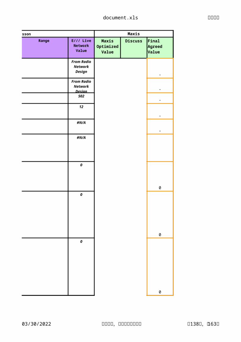
From Radio Network Design
From Radio Network Design
document.xls 文档密级
04/17/2023 华为机密,未经许可不得扩散 第139页,共163页
Huawei
Huawei Parameter Name Huawei RangeRNCID 0 to 4095CELLID 0 to 65535
MCC 000~999.
MNC 00~99 or 000~999
LACMAXALLOWEDULTXPOWER -50~33dBm
QQUALMIN -24~0dB
QRXLEVMINRAC H'00~H'FF(0~255).
FACHMEASOCCACYCLELENCOEF 1..12
INTER_RAT_PS_OUT_SWITCH ON,OFF
CELLBARRED BARRED, NOT_BARRED
CELLRESERVEDFOROPERATORUS RESERVED, NOT_RESERVED
QUALMEASTRESELECTIONS 0~31s
INTRAFREQRESELECTION ALLOWED, NOT_ALLOWED
UARFCNUPLINKUARFCNDOWNLINK
Band1: Common frequencies: [9612-9888]
Band1 Common frequencies: [10562-10838]
H'0000~H'FFFF(0~65535), except for H'0000 and H'FFFE.
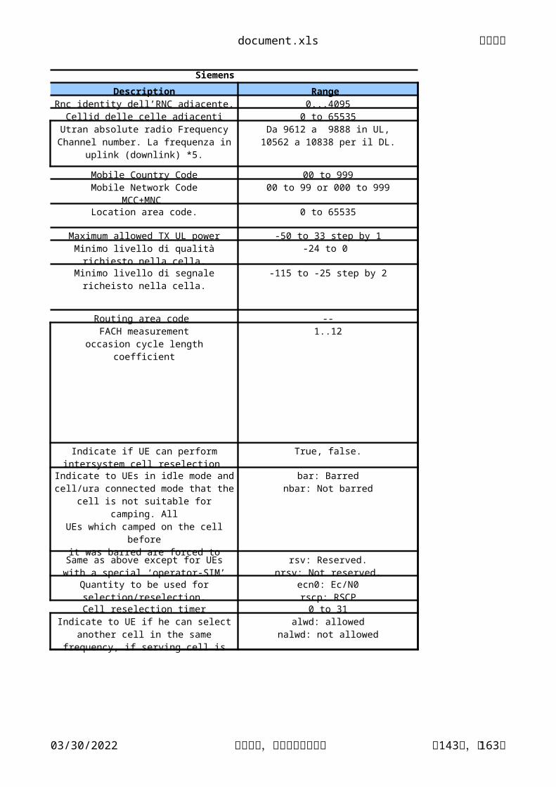
Description Range Rnc identity dell’RNC adiacente. 0...4095
Cellid delle celle adiacenti 0 to 65535
Mobile Country Code 00 to 99900 to 99 or 000 to 999
Location area code. 0 to 65535
Maximum allowed TX UL power -50 to 33 step by 1Minimo livello di qualità richiesto nella cella. -24 to 0
Minimo livello di segnale richeisto nella cella. -115 to -25 step by 2
Routing area code --1..12
True, false.
Quantity to be used for selection/reselection.
Cell reselection timer 0 to 31
Utran absolute radio Frequency Channel number. La frequenza in uplink (downlink) *5.
Da 9612 a 9888 in UL,10562 a 10838 per il DL.
Mobile Network CodeMCC+MNC
FACH measurementoccasion cycle length
coefficient
Indicate if UE can perform intersystem cell reselection
Indicate to UEs in idle mode andcell/ura connected mode that thecell is not suitable for camping. All
UEs which camped on the cell beforeit was barred are forced to select
another cell.
bar: Barrednbar: Not barred
Same as above except for UEswith a special ‘operator-SIM’
rsv: Reserved.nrsv: Not reserved.
ecn0: Ec/N0rscp: RSCP
Indicate to UE if he can select another cell in the same frequency, if serving cell is barred.
alwd: allowednalwd: not allowed
document.xls 文档密级
04/17/2023 华为机密,未经许可不得扩散 第144页,共163页
10, 20, 40, 80, 160, 320, 640, 1280
Threshold for intersystem measurements.
Defines the period in which the UE– while camping on another cell -shall exclude the
barred cell from the neighboring cell list
The hysteresis value Qhyst forGSM cells and for FDD cells in case the quality
measure for cell selection and re-selection is set to CPICH RSCP
0, ...,40 dBstep 2
The hysteresis value Qhyst used for FDD cells if the quality measure for cell selection and re-
selectionis set to CPICH Ec/N0.
0, ...,40 dBstep 2
This specifies the threshold for intra-frequency measurements and for the HCS measurement
rules.
-32,..., 20 dBstep of 2 dB
Threshold for interfrequency measurements of cell reselection.
-32,..., 20 dBstep of 2 dB
-32,..., 20 dBstep of 2 dB
document.xls 文档密级
04/17/2023 华为机密,未经许可不得扩散 第145页,共163页
Siemens Ericsson
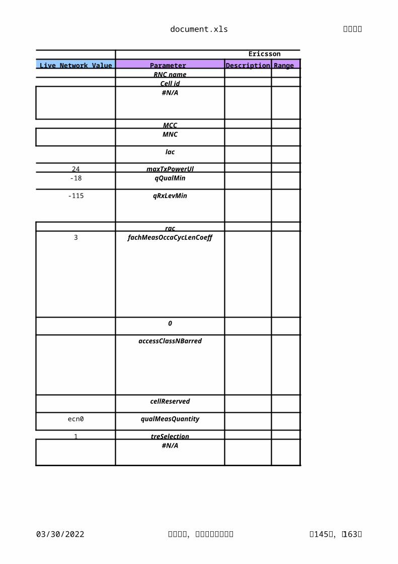
Live Network Value Parameter Description Range RNC name
Cell id#N/A
MCCMNC
lac
24 maxTxPowerUl-18 qQualMin
-115 qRxLevMin
rac3 fachMeasOccaCycLenCoeff
0
accessClassNBarred
cellReserved
ecn0 qualMeasQuantity
1 treSelection#N/A
document.xls 文档密级
04/17/2023 华为机密,未经许可不得扩散 第146页,共163页
0 qHyst1
2 qHyst2
14 sIntraSearch
8 sInterSearch
2 sRatSearch
H25
Author: new optimised
document.xls 文档密级
04/17/2023 华为机密,未经许可不得扩散 第147页,共163页
Ericsson Maxis
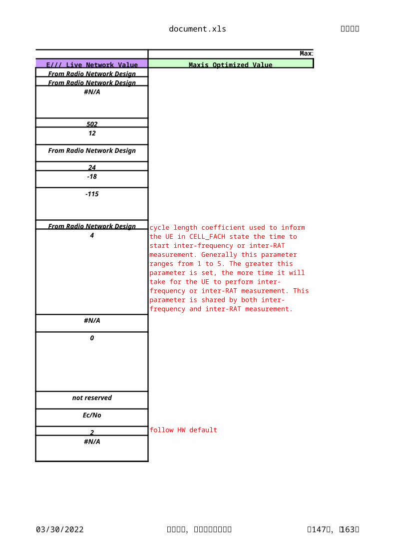
E/// Live Network Value Maxis Optimized ValueFrom Radio Network DesignFrom Radio Network Design
#N/A
50212
From Radio Network Design
24-18
-115
From Radio Network Design4
#N/A
0
not reserved
Ec/No
2 follow HW default
#N/A
Content: The FACH measurement occasion cycle length coefficient used to inform the UE in CELL_FACH state the time to start inter-frequency or inter-RAT measurement. Generally this parameter ranges from 1 to 5. The greater this parameter is set, the more time it will take for the UE to perform inter-frequency or inter-RAT measurement. This parameter is shared by both inter-frequency and inter-RAT measurement.
document.xls 文档密级
04/17/2023 华为机密,未经许可不得扩散 第148页,共163页
0
Y HW 4 dB?
0
HW default
0
Qmeas=Qqualmin+Thr =(-18)+14=-4 dB
0
Qmeas=Qqualmin+Thr =(-18)+8=-10 dB
2
2dB follow Maxis setting.
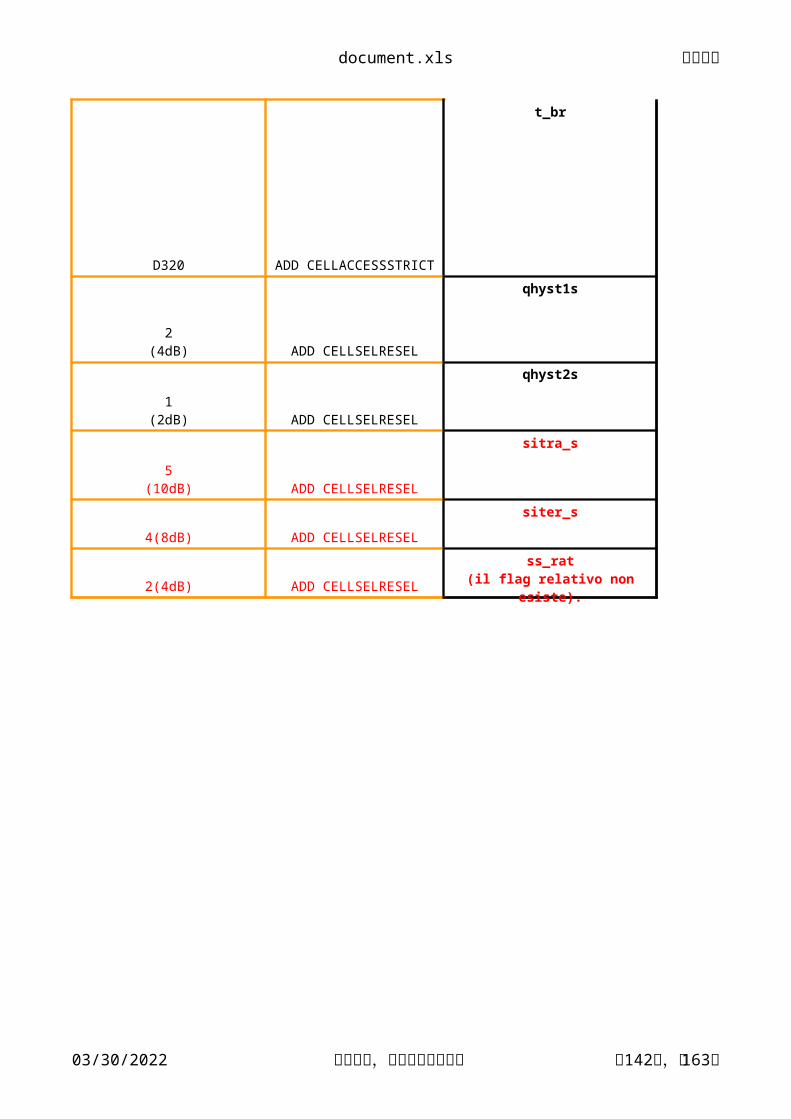
how this works? & y 320 s? Content: This parameter is valid when [Cell barred indicator] is BARRED. It indicates that the delay of the cell can be measured next time. The time barred can be increased or reduced in network planning based on the actual time the cell is barred.
Recommended value: None.
L25
Author: new optimised value
document.xls 文档密级
04/17/2023 华为机密,未经许可不得扩散 第149页,共163页
Maxis
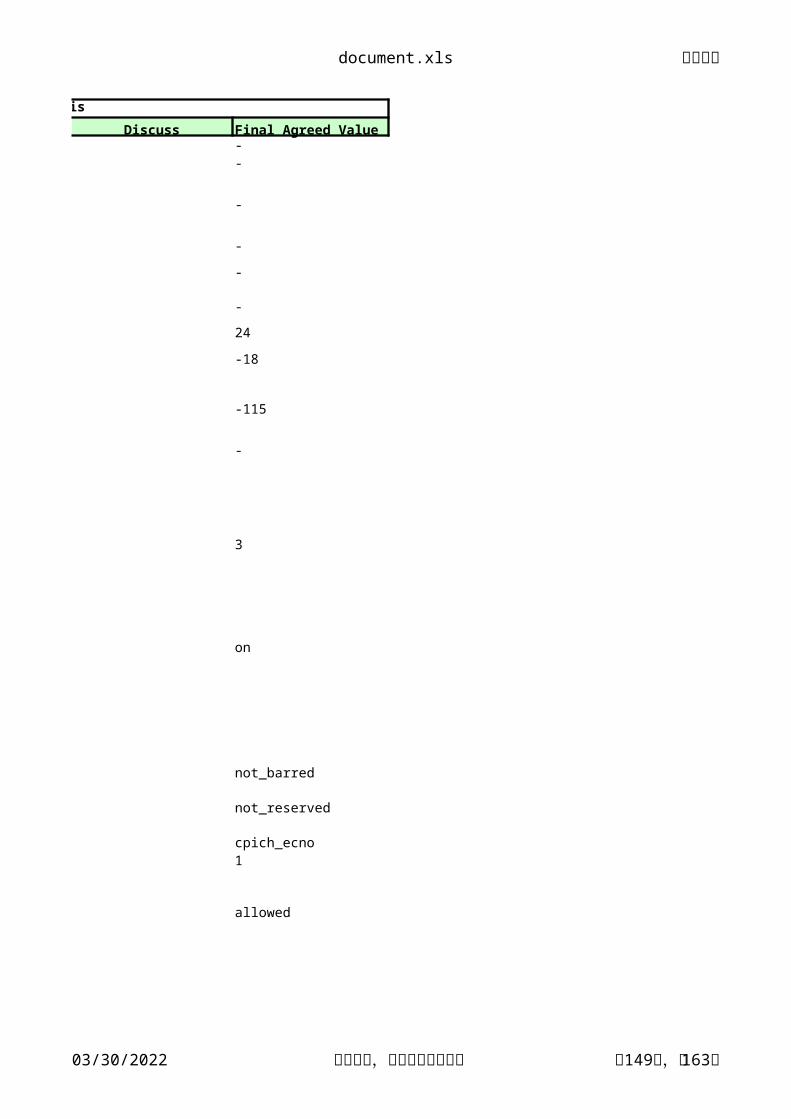
Discuss Final Agreed Value--
-
-
-
-
24
-18
-115
-
3
on
not_barred
not_reserved
cpich_ecno1
allowed
document.xls 文档密级
04/17/2023 华为机密,未经许可不得扩散 第150页,共163页
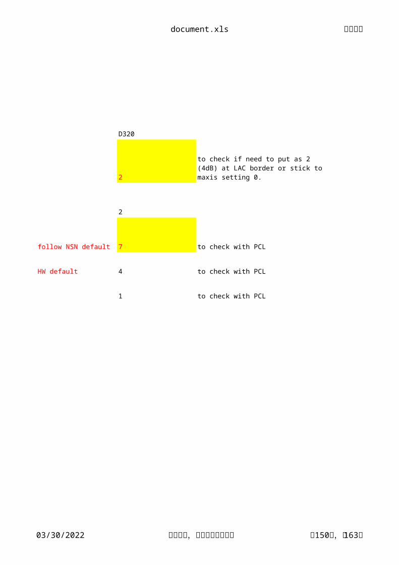
D320
2
2
follow NSN default 7 to check with PCL
HW default 4 to check with PCL
1 to check with PCL
to check if need to put as 2 (4dB) at LAC border or stick to maxis setting 0.
document.xls 文档密级
04/17/2023 华为机密,未经许可不得扩散 第151页,共163页
Huawei Siemens Huawei Range Parameter
NODEBNAME 1~31 characters - ADD NODEBSite name
NODEBID 0~65535. - ADD NODEB nodebid
RADIUS 150~180000m 10000m ADD LOCELL
GAIN - SET TMAGAIN
Null
Huawei Parameter Name
Huawei Proposed
Value
Huawei Command
0~255step:0.25dB
document.xls 文档密级
04/17/2023 华为机密,未经许可不得扩散 第152页,共163页
Siemens Ericsson
Description Range Live Network Value Parameter
Nome del sito Stringa alfanumerica #N/A
Identità del nodo B. 0…1023. #N/A
#N/A
1,2,3,off #N/A
On , off. #N/A
Tipo di nodo B #N/A
Indica il raggio di cella.Normal: up to 10 KmLarge: up to 20 Km
Very large: up to 50 Km
Cell Radius=C1/C2/C3
C1 (sector 1): N, L, VC2 (sector 2): N, L, VC3 (sector 3): N, L, V
N: NormalL: Large
V: Very large
Identifica il settore con TMA.
Indica if nodeB is equipped with booster.
880, 881, 440, 441, 341
document.xls 文档密级
04/17/2023 华为机密,未经许可不得扩散 第153页,共163页
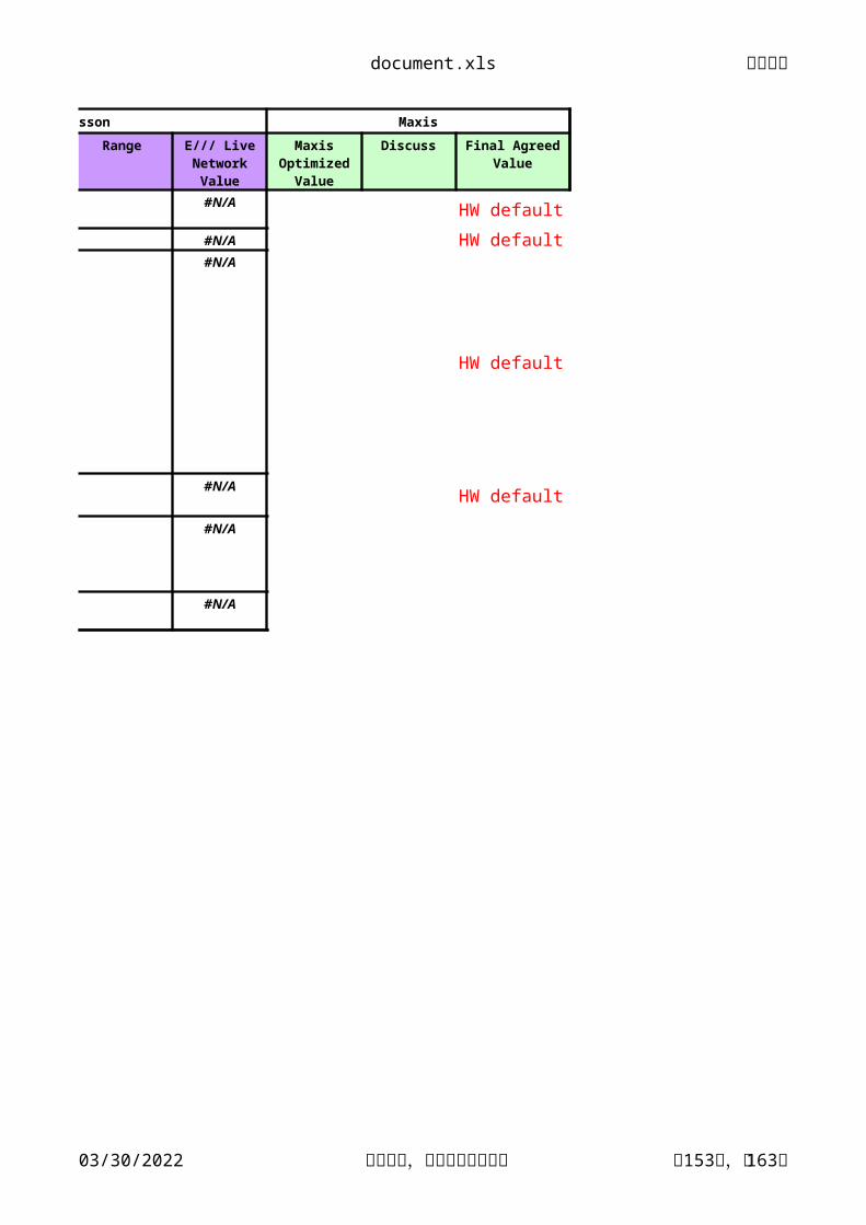
Ericsson Maxis
Description Range Discuss
#N/AHW default
#N/A HW default#N/A
HW default
#N/AHW default
#N/A
#N/A
E/// Live Network Value
Maxis Optimized
Value
Final Agreed Value
document.xls 文档密级
04/17/2023 华为机密,未经许可不得扩散 第154页,共163页
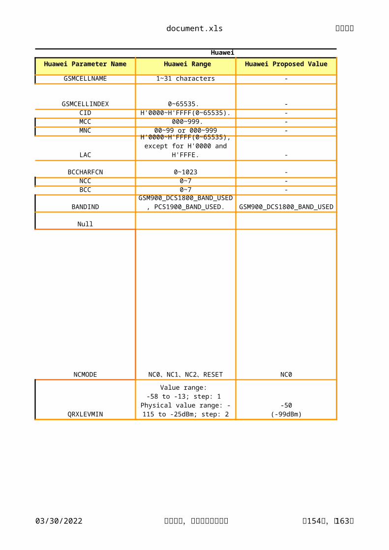
Huawei
Huawei Parameter Name Huawei Range
GSMCELLNAME 1~31 characters
GSMCELLINDEX 0~65535. CID H'0000~H'FFFF(0~65535).MCC 000~999.MNC 00~99 or 000~999
LAC
BCCHARFCN 0~1023NCC 0~7BCC 0~7
BANDIND
Null
NCMODE
QRXLEVMIN
H'0000~H'FFFF(0~65535), except for H'0000 and H'FFFE.
GSM900_DCS1800_BAND_USED, PCS1900_BAND_USED.
NC0、NC1、NC2、RESET
Value range: -58 to -13; step: 1
Physical value range: -115 to -25dBm; step: 2
document.xls 文档密级
04/17/2023 华为机密,未经许可不得扩散 第155页,共163页
Huawei Siemens
Huawei Proposed Value Huawei Command Parameter
- ADD GSMCELL Cell Name
- ADD GSMCELL
egcid
- ADD GSMCELL- ADD GSMCELL mcc- ADD GSMCELL mnc
- ADD GSMCELL
lac
- ADD GSMCELLarfcn
- ADD GSMCELL ncc- ADD GSMCELL bcc
ADD GSMCELLbandi
maut
NC0 ADD GSMCELL
mode_nc
ADD GSMNCELL
qrxlevmin
GSM900_DCS1800_BAND_USED
-50(-99dBm)
document.xls 文档密级
04/17/2023 华为机密,未经许可不得扩散 第156页,共163页
Siemens Ericsson
Description Range Live Network Value Parameter
GSM cell name. #N/A0..65535 #N/A
#N/AMCCMNC
Location area of GSM cell. 1 to 65533, 65535 lac
0..1023 #N/A
Network colour code #N/ABase station colour code #N/A
dcs #N/A
-50 to 33 dBm 33 #N/A
0..3 0 #N/A
-101 qRxLevMin
Identifies unambiguously the relationship between a UTRAN cell
and a GSM cell
Absolute Radio FrequencyNumber of the GSM cell
Indicates how to interpret the BCCH ARFCN
dcs: dcs_1800pcs: pcs_1900
Maximum allowed ULTX power
Controls the UE measurement behavior to be applied initially in
target GPRS cell:Value ‚0': The UE has to perform
normal UE controlled cell selection/re-selection procedure when camping on the target cell.Value ‚1' and ‚2': The UE has to
report measurements on adjacent cells, so that the 2G networkcould order cell reselection.
Value ‚3': The UE has to read the value for NC mode from 2G system
information first.
Specifies the minimal requiredRX level in the cell
-115,...,-25 dBmby step of 2 dBm
document.xls 文档密级
04/17/2023 华为机密,未经许可不得扩散 第157页,共163页
Ericsson Maxis
Description Range E/// Live Network Value Maxis Optimized Value Discuss
#N/A#N/A
#N/A50212
From Radio Network Design
#N/A
#N/A#N/A#N/A HW default
#N/A
#N/A
-105
Network Control Mode ( What is NC0 means in HW?)-HW to check what is this???
Why HW recommend -99dBm to Maxis instead of -101 dBm/ -105 dBm derived in E///, Siemens?
document.xls 文档密级
04/17/2023 华为机密,未经许可不得扩散 第158页,共163页
Maxis
Final Agreed Value
-
-
---
-
-
--
GSM900_DCS1800_BAND_USED
-105 dBm to check with PCL
document.xls 文档密级
04/17/2023 华为机密,未经许可不得扩散 第159页,共163页
Huawei
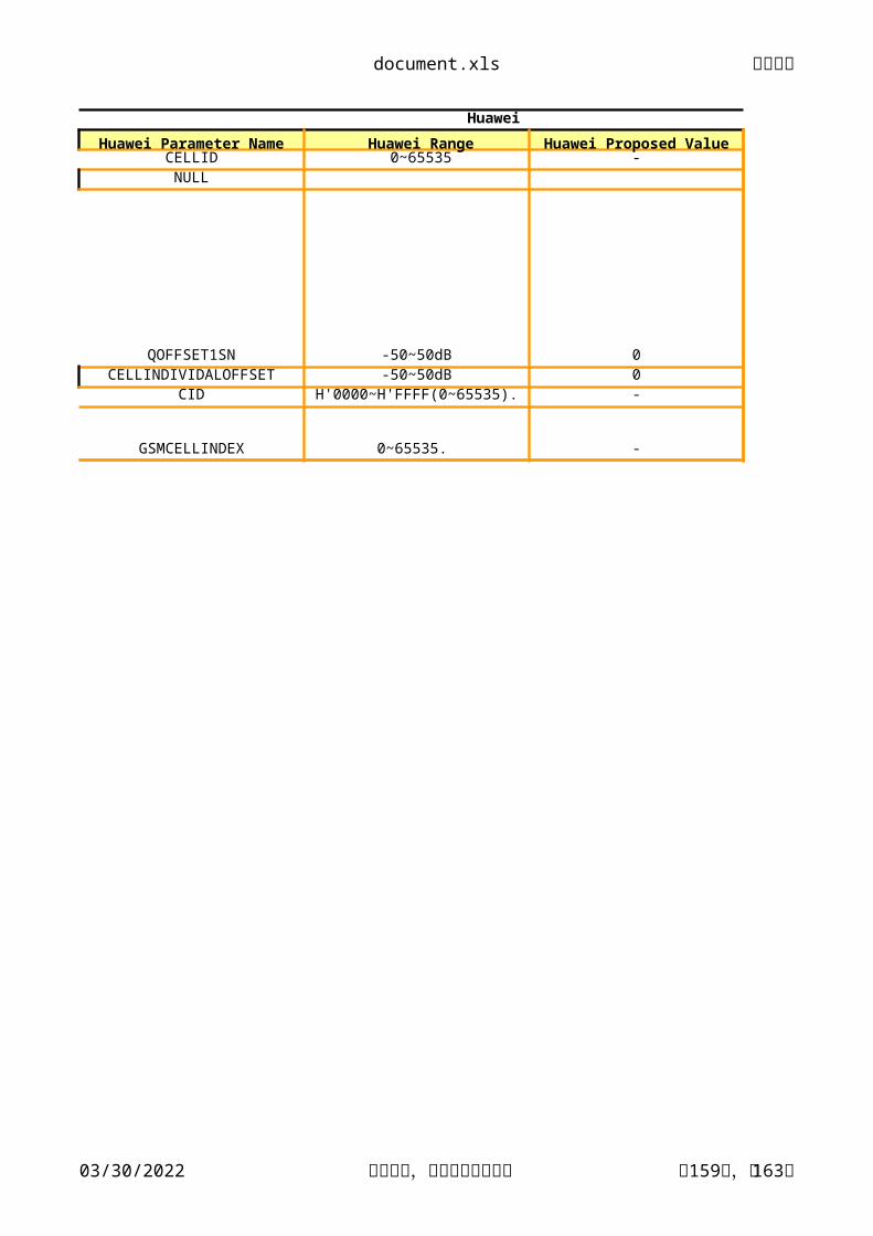
Huawei Parameter Name Huawei Range Huawei Proposed ValueCELLID 0~65535 -NULL
This specifies the offset between the two cells if the
quality measure for cell selection and re-selection is set to CPICH RSCP.In dB
Identifies unambiguously the relationship between a
UTRAN cell and a GSM cell.
document.xls 文档密级
04/17/2023 华为机密,未经许可不得扩散 第161页,共163页
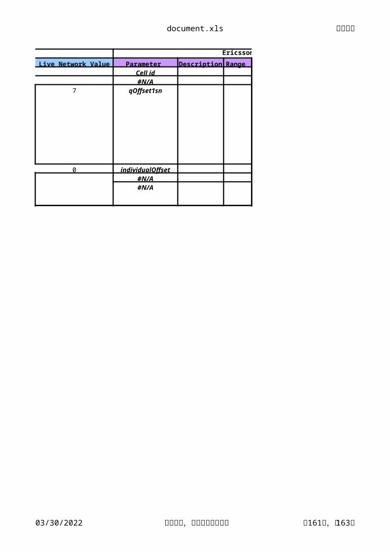
Siemens Ericsson
Live Network Value Parameter Description Range Cell id#N/A
7 qOffset1sn
0 individualOffset#N/A#N/A
document.xls 文档密级
04/17/2023 华为机密,未经许可不得扩散 第162页,共163页
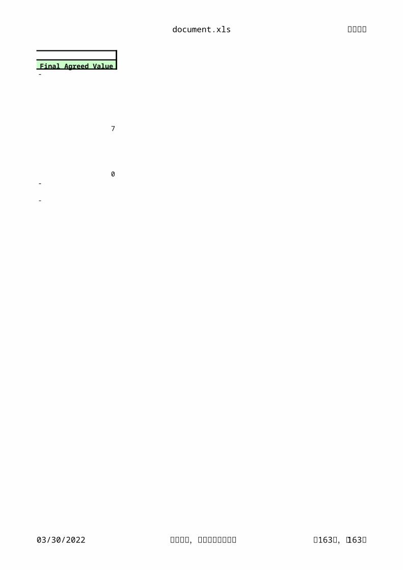
Ericsson Maxis
E/// Live Network Value Maxis Optimized Value DiscussFrom Radio Network Design
#N/A7
0#N/A 2G cellID#N/A
Content: In cell selection or reselection, the larger the parameter, the smaller the probability of selecting inter-RAT neighboring cells. The smaller the parameter, the larger the probability of selecting inter-RAT neighboring cells.
How HW works? Similar to Siemens? Looking for EGCID for GSM cells?


![Huawei Enterprise Wireless Solution V1[1].0 (20111031)](https://static.documents.pub/doc/80x56/577d23251a28ab4e1e991839/huawei-enterprise-wireless-solution-v110-20111031.jpg)

![Huawei Dual Cell HSDPA Technology White Paper V1[1].0(20100128)](https://static.documents.pub/doc/80x56/542c0f3b219acd9f178b458e/huawei-dual-cell-hsdpa-technology-white-paper-v11020100128.jpg)
