Human Factors Engineering • Flight Deck Design• Evaluation
9.3 Additional Considerations
Standardization • Error Management • Integration with Training/Qualifications and Procedures
References
9.1 Introduction
This chapter briefly describes Human Factors Engineering and considerations for civil aircraft flight deckdesign. The motivation for providing the emphasis on the Human Factor is that the operation of futureaviation systems will continue to rely on humans in the system for effective, efficient, and safe operation.Pilots, mechanics, air traffic service personnel, designers, dispatchers, and many others are the basis forsuccessful operations now and for the foreseeable future. There is ample evidence that failing to adequatelyconsider humans in the design and operations of these systems is at best inefficient and at worst unsafe.
This becomes especially important with the continuing advance of technology. Technology advanceshave provided a basis for past improvements in operations and safety and will continue to do so in thefuture. New alerting systems for terrain and traffic avoidance, data link communication systems toaugment voice-based radiotelephony, and new navigation systems based on Required Navigation Perfor-mance are just a few of the new technologies being introduced into flight decks.
Often, such new technology is developed and introduced to address known problems or to providesome operational benefit. While introduction of new technology may solve some problems, it oftenintroduces others. This has been true, for example, with the introduction of advanced automation.
1,2
Thus, while new technology can be part of a solution, it is important to remember that it will bringissues that may not have been anticipated and must be considered in the larger context (equipmentdesign, training, integration into existing flight deck systems, procedures, operations, etc.). These issuesare especially important to address with respect to the human operator.
The chapter is intended to help avoid vulnerabilities in the introduction of new technology andconcepts through the appropriate application of Human Factors Engineering in the design of flight decks.The chapter first introduces the fundamentals of Human Factors Engineering, then discusses the flightdeck design process. Different aspects of the design process are presented, with an emphasis on the
incorporation of Human Factors in flight deck design and evaluation. To conclude the chapter, someadditional considerations are raised.
9.2 Fundamentals
This section provides an overview of several topics that are fundamental to the application of HumanFactors Engineering (HFE) in the design of flight decks. It begins with a brief overview of Human Factors,then discusses the design process. Following that discussion, several topics that are important to theapplication of HFE are presented: the design philosophy, the interfaces and interaction between pilotsand flight decks, and the evaluation of the pilot/machine system.
9.2.1 Human Factors Engineering
It is not the purpose of this section to provide a complete tutorial on Human Factors. The area is quitebroad and the scientific and engineering knowledge about human behavior and human performance, andthe application of that knowledge to equipment design (among other areas), is much more extensive thancould possibly be cited here.
3–8
Nonetheless, a brief discussion of certain aspects of Human Factors isdesirable to provide the context for this chapter.
For the purposes of this chapter, Human Factors and its engineering aspects involve the applicationof knowledge about human capabilities and limitations to the design of technological systems.
9
HumanFactors Engineering also applies to training, personnel selection, procedures, and other topics, but thosetopics will not be expanded here.
Human capabilities and limitations can be categorized in many ways, with one example being theSHEL model.
6
This conceptual model describes the components
Software, Hardware, Environment, andLiveware
. The SHEL model, as described in Reference 6, is summarized below. The center of the model is the human, or
Liveware
. This is the hub of Human Factors. It is the mostvaluable and most flexible component of the system. However, the human is subject to many limitations,which are now predictable in general terms. The “edges” of this component are not simple or straight,and it may be said that the other components must be carefully matched to them to avoid stress in thesystem and suboptimal performance. To achieve this matching, it is important to understand the char-acteristics of this component:
•
Physical size and shape
— In the design of most equipment, body measurements and movementare important to consider at an early stage. There are significant differences among individuals,and the population to be considered must be defined. Data to make design decisions in this areacan be found in anthropometry and biomechanics.
•
Fuel requirements
— The human needs fuel (e.g., food, water, and oxygen) to function properly.Deficiencies can affect performance and well-being. This type of data is available from physiologyand biology.
•
Input characteristics
— The human has a variety of means for gathering input about the worldaround him or her. Light, sound, smell, taste, heat, movement, and touch are different forms ofinformation perceived by the human operator; for effective communication between a system andthe human operator, this information must be understood to be adequately considered in design.This knowledge is available from biology and physiology.
•
Information processing
— Understanding how the human operator processes the informationreceived is another key aspect of successful design. Poor human-machine interface or system designthat does not adequately consider the capabilities and limitations of the human informationprocessing system can strongly affect the effectiveness of the system. Short- and long-term memorylimitations are factors, as are the cognitive processing and decision-making processes used. Manyhuman errors can be traced to this area. Psychology, especially cognitive psychology, is a majorsource of data for this area.
— Once information is sensed and processed, messages are sent to themuscles and a feedback system helps to control their actions. Information about the kinds of forcesthat can be applied and the acceptable direction of controls are important in design decisions. Asanother example, speech characteristics are important in the design of voice communicationsystems. Biomechanics and physiology provide this type of information.
•
Environmental tolerances
— People, like equipment, are designed to function effectively onlywithin a narrow range of environmental conditions such as temperature, pressure, noise, humidity,time of day, light, and darkness. Variations in these conditions can all be reflected in performance.A boring or stressful working environment can also affect performance. Physiology, biology, andpsychology all provide relevant information on these environmental effects.
It must be remembered that humans can vary significantly in these characteristics. Once the effectsof these differences are identified, some of them can be controlled in practice through selection, training,and standardized procedures. Others may be beyond practical control and the overall system must bedesigned to accommodate them safely. This
Liveware
is the hub of the conceptual model. For successfuland effective design, the remaining components must be adapted and matched to this central component.
The first of the components that requires matching to the characteristics of the human is
Hardware
.This interface is the one most generally thought of when considering human-machine systems. Anexample is designing seats to fit the sitting characteristics of the human. More complex is the design ofdisplays to match the human’s information processing characteristics. Controls, too, must be designedto match the human’s characteristics, or problems can arise from, for example, inappropriate movementor poor location. The user is often unaware of mismatches in this liveware-hardware interface. The naturalhuman characteristic of adapting to such mismatches masks but does not remove their existence. Thusthis mismatch represents a potential hazard to which designers should be alerted.
The second interface with which Human Factors Engineering is concerned is that between Livewareand Software. This encompasses the nonphysical aspects of the systems such as procedures, manual andchecklist layout, symbology, and computer programs. The problems are often less tangible than in theLiveware-Hardware interface and more difficult to resolve.
One of the earliest interfaces recognized in flying was between the human and the environment. Pilotswere fitted with helmets against the noise, goggles against the airstream, and oxygen masks against thealtitude. As aviation matured, the environment became more adapted to the human (e.g., through pres-surized aircraft). Other aspects that have become more of an issue are disturbed biological rhythms andrelated sleep disturbances because of the increased economic need to keep aircraft, and the humans thatoperate them, flying 24 hours a day. The growth in air traffic and the resulting complexities in operationsare other aspects of the environment that are becoming increasingly significant now and in the future.
The last major interface described by the SHEL model is the human-human interface. Traditionally,questions of performance in flight have focused on individual performance. Increasingly, attention isbeing paid to the performance of the team or group. Pilots fly as a crew; flight attendants work as a team;maintainers, dispatchers, and others operate as groups; therefore, group dynamics and influences areimportant to consider in design.
The SHEL model is a useful conceptual model, but other perspectives are important in design as well.The reader is referred to the references cited for in-depth discussion of basic human behavioral consid-erations, but a few other topics are especially relevant to this chapter and are discussed here: usability,workload, and situation awareness.
9.2.1.1 Usability
The usability of a system is very pertinent to its acceptability by users; therefore, it is a key element tothe success of a design. Nielsen
10
defines usability as having multiple components:
• Learnability — the system should be easy to learn
• Efficiency — the system should be efficient to use
• Memorability — the system should be easy to remember
• Error — the system should be designed so that users make few errors during use of the system,and can easily recover from those they do make
• Satisfaction — the system should be pleasant to use, so users are subjectively satisfied when using it.
This last component is indicated by subjective opinion and preference by the user. This is importantfor acceptability, but it is critical to understand that there is a difference between subjective preferenceand performance of the human-machine system. In some cases, the design that was preferred by the userwas not the design that resulted in the best performance. This illustrates the importance of both subjectiveinput from representative end users and objective performance evaluation.
9.2.1.2 Workload
In the context of the commercial flight deck, workload is a multidimensional concept consisting of: (1)the duties, amount of work, or number of tasks that a flight crew member must accomplish; (2) theduties of the flight crew member with respect to a particular time interval during which those dutiesmust be accomplished; and/or (3) the subjective experience of the flight crew member while performingthose duties in a particular mission context. Workload may be either physical or mental.
11
Both overload (high workload, potentially resulting in actions being skipped or executed incorrectlyor incompletely) and underload (low workload, leading to inattention and complacency) are worthy ofattention when considering the effect of design on human-machine performance.
9.2.1.3 Situation Awareness
This can be viewed as the perception on the part of a flight crew member of all the relevant pieces ofinformation in both the flight deck and the external environment, the comprehension of their effects onthe current mission status, and the projection of the values of these pieces of information (and theireffect on the mission) into the near future.
11
Situation awareness has been cited as an issue in many incidents and accidents, and can be consideredas important as workload. As part of the design process, the pilot’s information requirements must beidentified, and the information display must be designed to ensure adequate situation awareness.Although the information is available in the flight deck, it may not be in a form that is directly usableby the pilot, and therefore of little value.
Another area that is being increasingly recognized as important is the topic of organizational processes,policies and practices.
12
It has become apparent that the influence of these organizational aspects is asignificant, if latent, contributor to potential vulnerabilities in design and operations.
9.2.2 Flight Deck Design
The process by which commercial flight decks are designed is complex, largely unwritten, variable, andnonstandard.
11
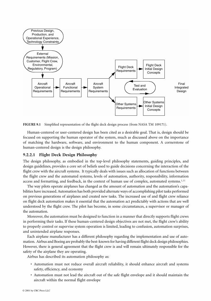
That said, Figure 9.1 is an attempt to describe this process in a generic manner. Itrepresents a composite flight deck design process based on various design process materials. The figureis not intended to exactly represent the accepted design process within any particular organization orprogram; however, it is meant to be descriptive of generally accepted design practice. (For more detaileddiscussion of design processes for pilot-system integration and integration of new systems into existingflight decks, see References 13 and 14.)
The figure is purposely oversimplified. For example, the box labeled “Final Integrated Design” encompassesan enormous number of design and evaluation tasks, and can take years to accomplish. It could be expandedinto a figure of its own that includes not only the conceptual and actual integration of flight deck components,but also analyses, simulations, flight tests, certification and integration based on these evaluations.
Flight deck design necessarily requires the application of several disciplines, and often requires trade-offsamong those disciplines. Human Factors Engineering is only one of the disciplines that should be part ofthe process, but it is a key part of ensuring that the flight crew’s capabilities and limitations are considered.Historically, this process tends to be very reliant on the knowledge and experiences of individuals involvedin each program.
Human-centered or user-centered design has been cited as a desirable goal. That is, design should befocused on supporting the human operator of the system, much as discussed above on the importanceof matching the hardware, software, and environment to the human component. A cornerstone ofhuman-centered design is the design philosophy.
9.2.2.1 Flight Deck Design Philosophy
The design philosophy, as embodied in the top-level philosophy statements, guiding principles, anddesign guidelines, provides a core set of beliefs used to guide decisions concerning the interaction of theflight crew with the aircraft systems. It typically deals with issues such as allocation of functions betweenthe flight crew and the automated systems, levels of automation, authority, responsibility, informationaccess and formatting, and feedback, in the context of human use of complex, automated systems.
1,11
The way pilots operate airplanes has changed as the amount of automation and the automation’s capa-bilities have increased. Automation has both provided alternate ways of accomplishing pilot tasks performedon previous generations of airplanes and created new tasks. The increased use of and flight crew relianceon flight deck automation makes it essential that the automation act predictably with actions that are wellunderstood by the flight crew. The pilot has become, in some circumstances, a supervisor or manager ofthe automation.
Moreover, the automation must be designed to function in a manner that directly supports flight crewsin performing their tasks. If these human-centered design objectives are not met, the flight crew’s abilityto properly control or supervise system operation is limited, leading to confusion, automation surprises,and unintended airplane responses.
Each airplane manufacturer has a different philosophy regarding the implementation and use of auto-mation. Airbus and Boeing are probably the best-known for having different flight deck design philosophies.However, there is general agreement that the flight crew is and will remain ultimately responsible for thesafety of the airplane they are operating.
Airbus has described its automation philosophy as:
• Automation must not reduce overall aircraft reliability, it should enhance aircraft and systemssafety, efficiency, and economy
• Automation must not lead the aircraft out of the safe flight envelope and it should maintain theaircraft within the normal flight envelope
FIGURE 9.1
Simplified representation of the flight deck design process (from NASA TM 109171).
• Automation should allow the operator to use the safe flight envelope to its full extent, should thisbe necessary due to extraordinary circumstances
• Within the normal flight envelope, the automation must not work against operator inputs, exceptwhen absolutely necessary for safety
Boeing has described its philosophy as follows:
• The pilot is the final authority for the operation of the airplane
• Both crew members are ultimately responsible for the safe conduct of the flight
• Flight crew tasks, in order of priority, are safety, passenger comfort, and efficiency
• Design for crew operations based on pilot’s past training and operational experience
• Design systems to be error tolerant
• The hierarchy of design alternatives is simplicity, redundancy, and automation
• Apply automation as a tool to aid, not replace, the pilot
• Address fundamental human strengths, limitations, and individual differences — for both normaland nonnormal operations
• Use new technologies and functional capabilities only when:
• They result in clear and distinct operational or efficiency advantages, and
• There is no adverse effect to the human-machine interface
One of the significant differences between the design philosophies of the two manufacturers is in thearea of envelope protection. Airbus’ philosophy has led to the implementation of what has been describedas “hard” limits, where the pilot can provide whatever control inputs he or she desires, but the airplanewill not exceed the flight envelope. In contrast, Boeing has “soft” limits, where the pilot will meetincreasing resistance to control inputs that will take the airplane beyond the normal flight envelope, butcan do so if he or she chooses. In either case, it is important for the pilot to understand what the designphilosophy is for the airplane being flown.
Other manufacturers may have philosophies that differ from Boeing and Airbus. Different philosophiescan be effective if each is consistently applied in design, training, and operations, and if each supportsflight crew members in flying their aircraft safely. To ensure this effectiveness, it is critical that the designphilosophy be documented explicitly and provided to the pilots who will be operating the aircraft, thetrainers, and the procedure developers.
9.2.2.2 Pilot/Flight Deck Interfaces
The layout, controls, displays and amount of automation in flight decks have evolved tremendously incommercial aviation.
15,16
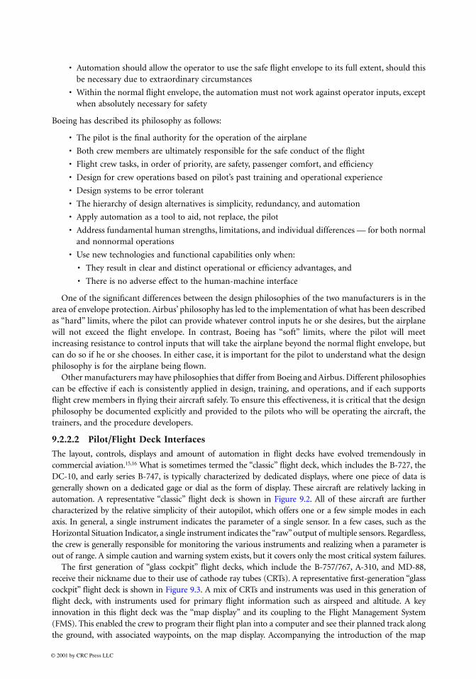
What is sometimes termed the “classic” flight deck, which includes the B-727, theDC-10, and early series B-747, is typically characterized by dedicated displays, where one piece of data isgenerally shown on a dedicated gage or dial as the form of display. These aircraft are relatively lacking inautomation. A representative “classic” flight deck is shown in Figure 9.2. All of these aircraft are furthercharacterized by the relative simplicity of their autopilot, which offers one or a few simple modes in eachaxis. In general, a single instrument indicates the parameter of a single sensor. In a few cases, such as theHorizontal Situation Indicator, a single instrument indicates the “raw” output of multiple sensors. Regardless,the crew is generally responsible for monitoring the various instruments and realizing when a parameter isout of range. A simple caution and warning system exists, but it covers only the most critical system failures.
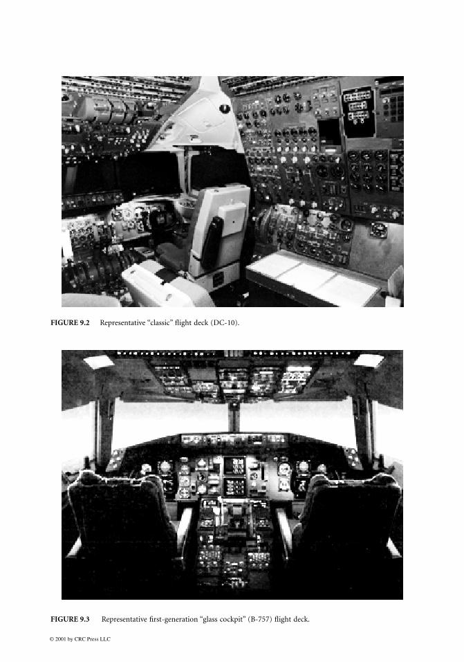
The first generation of “glass cockpit” flight decks, which include the B-757/767, A-310, and MD-88,receive their nickname due to their use of cathode ray tubes (CRTs). A representative first-generation “glasscockpit” flight deck is shown in Figure 9.3. A mix of CRTs and instruments was used in this generation offlight deck, with instruments used for primary flight information such as airspeed and altitude. A keyinnovation in this flight deck was the “map display” and its coupling to the Flight Management System(FMS). This enabled the crew to program their flight plan into a computer and see their planned track alongthe ground, with associated waypoints, on the map display. Accompanying the introduction of the map
display and FMS were more complex autopilots (added modes from the FMS and other requirements). Thisgeneration of aircraft also featured the introduction of an integrated Caution and Warning System, usuallydisplayed in a center CRT with engine information. A major feature of this Caution and Warning Systemwas that it prioritized alerts according a strict hierarchy of “warnings” (immediate crew action required),“cautions” (immediate crew awareness and future action required), and “advisories” (crew awareness andpossible action required).
17
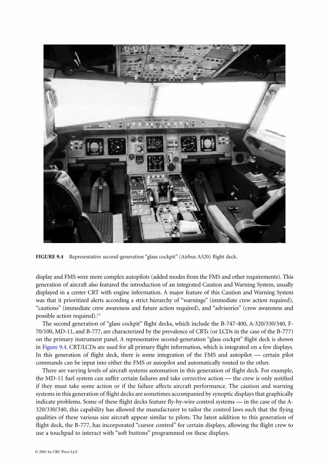
The second generation of “glass cockpit” flight decks, which include the B-747-400, A-320/330/340, F-70/100, MD-11, and B-777, are characterized by the prevalence of CRTs (or LCDs in the case of the B-777)on the primary instrument panel. A representative second-generation “glass cockpit” flight deck is shownin Figure 9.4. CRT/LCDs are used for all primary flight information, which is integrated on a few displays.In this generation of flight deck, there is some integration of the FMS and autopilot — certain pilotcommands can be input into either the FMS or autopilot and automatically routed to the other.
There are varying levels of aircraft systems automation in this generation of flight deck. For example,the MD-11 fuel system can suffer certain failures and take corrective action — the crew is only notifiedif they must take some action or if the failure affects aircraft performance. The caution and warningsystems in this generation of flight decks are sometimes accompanied by synoptic displays that graphicallyindicate problems. Some of these flight decks feature fly-by-wire control systems — in the case of the A-320/330/340, this capability has allowed the manufacturer to tailor the control laws such that the flyingqualities of these various size aircraft appear similar to pilots. The latest addition to this generation offlight deck, the B-777, has incorporated “cursor control” for certain displays, allowing the flight crew touse a touchpad to interact with “soft buttons” programmed on these displays.
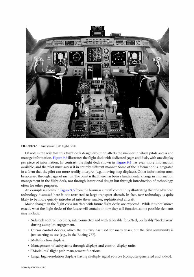
Of note is the way that this flight deck design evolution affects the manner in which pilots access andmanage information. Figure 9.2 illustrates the flight deck with dedicated gages and dials, with one displayper piece of information. In contrast, the flight deck shown in Figure 9.4 has even more informationavailable, and the pilot must access it in entirely different manner. Some of the information is integratedin a form that the pilot can more readily interpret (e.g., moving map displays). Other information mustbe accessed through pages of menus. The point is that there has been a fundamental change in informationmanagement in the flight deck, not through intentional design but through introduction of technology,often for other purposes.
An example is shown in Figure 9.5 from the business aircraft community illustrating that the advancedtechnology discussed here is not restricted to large transport aircraft. In fact, new technology is quitelikely to be more quickly introduced into these smaller, sophisticated aircraft.
Major changes in the flight crew interface with future flight decks are expected. While it is not knownexactly what the flight decks of the future will contain or how they will function, some possible elementsmay include:
• Sidestick control inceptors, interconnected and with tailorable force/feel, preferably “backdriven”during autopilot engagement.
• Cursor control devices, which the military has used for many years, but the civil community isjust starting to use (e.g., in the Boeing 777).
• Multifunction displays.
• Management of subsystems through displays and control-display units.
• ‘‘Mode-less” flight path management functions.
• Large, high-resolution displays having multiple signal sources (computer-generated and video).
• Graphical interfaces for managing certain flight deck systems.
• High-bandwidth, two-way datalink communication capability embedded in appropriate flightdeck systems
• Replacement of paper with “electronic flight bags.’’
• Voice interfaces for certain flight deck systems.
These changes will continue to modify the manner in which pilots manage information within theflight deck, and the effect of such changes should be explicitly considered in the flight deck design process.
9.2.2.3 Pilot/Flight Deck Interaction
Although it is common to consider the pilot interfaces to be the only or primary consideration in humanfactors in flight deck design, the interaction between the pilot(s) and the flight deck must also beconsidered. Some of the most visible examples of the importance of this topic, and the consequences ofvulnerabilities in this area, are in the implementation of advanced automation.
Advanced automation (sophisticated autopilots, autothrust, flight management systems, and associateddisplays and controls) has provided large improvements in safety (e.g., through reduced pilot workload incritical or long-range phases of flight) and efficiency (improved precision of flying certain flight paths).However, vulnerabilities have been identified in the interaction between the flight crews and modern systems.
2
For example, on April 26, 1994, an Airbus A300–600 operated by China Airlines crashed at Nagoya,Japan killing 264 passengers and flight crew members. Contributing to the accident were conflictingactions taken by the flight crew and the airplane’s autopilot. During complex circumstance, the flightcrew attempted to stay on glide slope by commanding nose-down elevator. The autopilot was thenengaged, and because it was still in go-around mode, commanded nose-up trim. A combination of anout-of-trim condition, high engine thrust, and retracting the flaps too far led to a stall. The crash provideda stark example of how a breakdown in the flight crew/automation interaction can affect flight safety.Although this particular accident involved an A300–600, other accidents, incidents, and safety indicatorsdemonstrate that this problem is not confined to any one airplane type, airplane manufacturer, operator,or geographical region.
A lesson to be learned here is that design of the interaction between the pilot and the systems mustconsider human capabilities and limitations. A good human-machine interface is necessary but may notbe sufficient to ensure that the system is usable and effective. The interaction between the pilot and thesystem, as well as the function of the system itself, must be carefully “human engineered.’’
9.2.3 Evaluation
Figure 9.1 showed test and evaluation (or just evaluation, for the remainder of the discussion) as anintegral part of the design process. Because evaluation is (or should be) such an important part of design,some clarifying discussion is appropriate here. (See Reference 18 for a more detailed discussion of theevaluation issues that are summarized below.)
Evaluation often is divided into verification (the process of demonstrating that the system works asdesigned) and validation (the process of assessing the degree to which the design achieves the systemobjectives of interest). Thus, validation goes beyond asking whether the system was built according tothe plan or specifications; it determines whether the plan or specifications were correct for achieving thesystem objectives.
One common use of the term “evaluation” is as a synonym of “demonstration.” That is, evaluationinvolves turning on the system and seeing if it basically resembles what the designer intended. This doesnot, however, provide definitive information on safety, economy, reliability, maintainability, or otherconcerns that are generally the motivation for evaluation.
It is not unusual for evaluation to be confused with demonstration, but they are not the same. Inaddition, there are several different types and levels of evaluation that are useful to understand. Forexample,
formative
evaluation is performed during the design process. It tends to be informal and
subjective, and its results should be viewed as hypotheses, not definitive results. It is often used toevaluate requirements. In contrast,
formal
evaluation is planned during the design but performed witha prototype to assess the performance of the human/machine system. Both types of evaluations arerequired, but the rest of this discussion focuses on formal evaluation.
Another distinction of interest in understanding types of evaluation is the difference between
absolute
vs.
comparative
evaluations.
Absolute
evaluation is used when assessing against a standard of some kind.An example would be evaluating whether the pilot’s response time using a particular system is less thansome prespecified number.
Comparative
evaluation compares one design to another, typically an olddesign to a new one. Evaluating whether the workload for particular tasks in a new flight deck is equalto or less than in an older model is an example comparative evaluation. This type of evaluation is oftenused in the airworthiness certification of a new flight deck, to show its acceptability relative to an older,already certified flight deck. It may be advantageous for developers to expand an absolute evaluation intoa comparative evaluation (through options within the new system) to assess system sensitivities.
Yet another important distinction is between
objective
vs.
subjective
evaluation.
Objective
evaluationmeasures the degree to which the objective criteria (based on system objectives) have been met.
Subjective
evaluation focuses on users’ opinions and preferences. Subjective data are important but should be usedto support the objective results, not replace them.
Planning for the evaluation should proceed in parallel with design rather than after the design issubstantially completed. Evaluation should lead to design modification, and this is most effectively donein an iterative fashion.
Three basic issues, or levels of evaluation, are worth considering. The first is
compatibility
. That is,the physical presentation of the system must be compatible with human input and output characteristics.The pilot has to be able to read the displays, reach the controls, etc. Otherwise, it doesn’t matter howgood the system design is; it will not be usable.
Compatibility is important but not sufficient. A second issue is
understandability
. That is, just becausethe system is compatible with human input-output capabilities and limitations does not necessarily meanthat it is understandable. The structure, format, and content of the pilot-machine dialogue must resultin meaningful communication. The pilot must be able to interpret the information provided, and beable to “express” to the system what he or she wishes to communicate. For example, if the pilot can readthe menu, but the options available are meaningless, that design is not satisfactory.
A designer must ensure that the design is both compatible and understandable. Only then should thethird level of evaluation be addressed: that of
effectiveness
. A system is effective to the extent that itsupports a pilot or crew in a manner that leads to improved performance, results in a difficult task beingmade less difficult, or enables accomplishing a task that otherwise could not have been accomplished.Assessing effectiveness depends on defining measures of performance based on the design objectives.Regardless of these measures, there is no use in attempting to evaluate effectiveness until compatibilityand understandability are ensured.
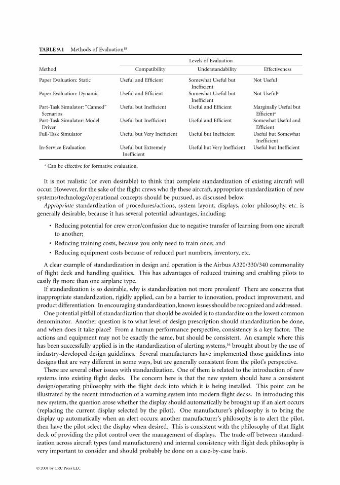
Several different methods of evaluation can be used, ranging from static paper-based evaluations toin-service experience. The usefulness and efficiency of a particular method of evaluation naturallydepends on what is being evaluated. Table 9.1 shows the usefulness and efficiency of several methods foreach of the levels of evaluation.
As can be seen from this discussion, evaluation is an important and integral part of successful design.
9.3 Additional Considerations
9.3.1 Standardization
Generally, across manufacturers, there is a great deal of variation in existing flight deck systems design,training, and operation. Because pilots often operate different aircraft types, or similar aircraft withdifferent equipage, at different points in time, another way to avoid or reduce errors is standardizationof equipment, actions, and other areas.
It is not realistic (or even desirable) to think that complete standardization of existing aircraft willoccur. However, for the sake of the flight crews who fly these aircraft, appropriate standardization of newsystems/technology/operational concepts should be pursued, as discussed below.
Appropriate
standardization of procedures/actions, system layout, displays, color philosophy, etc. isgenerally desirable, because it has several potential advantages, including:
• Reducing potential for crew error/confusion due to negative transfer of learning from one aircraftto another;
• Reducing training costs, because you only need to train once; and
• Reducing equipment costs because of reduced part numbers, inventory, etc.
A clear example of standardization in design and operation is the Airbus A320/330/340 commonalityof flight deck and handling qualities. This has advantages of reduced training and enabling pilots toeasily fly more than one airplane type.
If standardization is so desirable, why is standardization not more prevalent? There are concerns thatinappropriate standardization, rigidly applied, can be a barrier to innovation, product improvement, andproduct differentiation. In encouraging standardization, known issues should be recognized and addressed.
One potential pitfall of standardization that should be avoided is to standardize on the lowest commondenominator. Another question is to what level of design prescription should standardization be done,and when does it take place? From a human performance perspective, consistency is a key factor. Theactions and equipment may not be exactly the same, but should be consistent. An example where thishas been successfully applied is in the standardization of alerting systems,
16
brought about by the use ofindustry-developed design guidelines. Several manufacturers have implemented those guidelines intodesigns that are very different in some ways, but are generally consistent from the pilot’s perspective.
There are several other issues with standardization. One of them is related to the introduction of newsystems into existing flight decks. The concern here is that the new system should have a consistentdesign/operating philosophy with the flight deck into which it is being installed. This point can beillustrated by the recent introduction of a warning system into modern flight decks. In introducing thisnew system, the question arose whether the display should automatically be brought up if an alert occurs(replacing the current display selected by the pilot). One manufacturer’s philosophy is to bring thedisplay up automatically when an alert occurs; another manufacturer’s philosophy is to alert the pilot,then have the pilot select the display when desired. This is consistent with the philosophy of that flightdeck of providing the pilot control over the management of displays. The trade-off between standard-ization across aircraft types (and manufacturers) and internal consistency with flight deck philosophy isvery important to consider and should probably be done on a case-by-case basis.
The timing of standardization, especially with respect to introduction of new technology, is alsocritical.
4
It is desirable to deploy new technology early, because some problems are only found in theactual operating environment. However, if we standardize too early, then there is a risk of standardizingon a design that has not accounted for that critical early in-service experience. We may even uninten-tionally standardize a design that is error inducing. However, attempt to standardize too late and theremay already be so many variations that no standard can be agreed upon. It is clear that standardizationmust be done carefully and wisely.
9.3.2 Error Management
Human error, especially flight crew error, is a recurring theme and continues to be cited as a primaryfactor in a majority of aviation accidents.
2,20
It is becoming increasingly recognized that this issue mustbe taken on in a systematic way, or it may prove difficult to make advances in operations and safetyimprovements. However, it is also important to recognize that human error is also a normal by-productof human behavior, and most errors in aviation do not have safety consequences. Therefore, it isimportant for the aviation community to recognize that error cannot be completely prevented and thatthe focus should be on error management.
In many accidents where human error is cited, the human operator is blamed for making the error;in some countries the human operator is assigned criminal responsibility, and even some U.S. prosecutorsseem willing to take similar views. While the issue of personal responsibility for the consequences ofone’s actions is important and relevant, it also is important to understand why the individual or crewmade the error(s). In aviation, with very rare exceptions, flight crews (and other humans in the system)do not intend to make errors, especially errors with safety consequences. To improve safety throughunderstanding of human error, it may be more useful to address errors as
symptoms
rather than
causes
of accidents. The next section discusses understanding of error and its management, then suggests someactions that might be constructive.
Human error can be distinguished into two basic categories: (a) those which presume the intentionis correct, but the action is incorrect, (including
slips
and
lapses
), and (b) those in which the intentionis wrong (including
mistakes
and
violations
).
21–23
Slips
are where one or more incorrect actions are performed, such as in a substitution or insertion ofan inappropriate action into a sequence that was otherwise good. An example would be settingthe wrong altitude into the mode selector panel, even when the pilot knew the correct altitudeand intended to enter it.
Lapses
are the omission of one or more steps of a sequence. For example, missing one or more itemsin a checklist that has been interrupted by a radio call.
Mistakes
are errors where the human did what he or she intended, but the planned action was incorrect.Usually mistakes are the result of an incorrect diagnosis of a problem or a failure to understandthe exact nature of the current situation. The plan of action thus derived may contain veryinappropriate behaviors and may also totally fail to rectify a problem. For example, a mistakewould be shutting down the wrong engine as a result of an incorrect diagnosis of a set of symptoms.
Violations
are the failure to follow established procedures or performance of actions that are generallyforbidden. Violations are generally deliberate (and often well-meaning), though an argument canbe made that some violation cases can be inadvertent. An example of a violation is continuingon with a landing even when weather minima have not been met before final approach. It shouldbe mentioned that a “violation” error may not necessarily be in violation of a regulation or otherlegal requirement.
Understanding differences in the types of errors is valuable because management of different typesmay require different strategies. For example, training is often proposed as a strategy for preventingerrors. However, errors are a normal by-product of human behavior. While training can help reducesome types of errors, they cannot be completely trained out. For that reason, errors should also be
addressed by other means, and considering other factors, such as the consequences of the error or whetherthe effect of the error can be reversed. As an example of using design to address known potential errors,certain switches in the flight deck have guards on them to prevent inadvertent activation.
Error management can be viewed as involving the tasks of error avoidance, error detection, and errorrecovery.
23
Error avoidance is important, because it is certainly desirable to prevent as many errors aspossible. Error detection and recovery are important, and in fact it is the safety consequences of errorsthat are most critical.
It seems clear that experienced pilots have developed skills for performing error management tasks.Therefore, it is possible that design, training, and procedures can directly support these tasks, if we geta better understanding of those skills and tasks. However, the understanding of those skills and tasks isfar from complete.
There are a number of actions that should be taken with respect to dealing with error, some of themin the design process:
Stop the blame
that inhibits in-depth addressing of human error, while appropriately acknowledg-ing the need for individual and organizational responsibility for safety consequences. The issueof blaming the pilot for errors has many consequences, and provides a disincentive to reporterrors.
Evaluate errors in accident and incident analyses
. In many accident analyses, the reason an error is madeis not addressed. This typically happens because the data are not available. However, to the extentpossible with the data available, the types of errors and reasons for them should be addressed as partof the accident investigation.
Develop a better understanding of error management tasks and skills
that can support betterperformance of those tasks. This includes:
• Preventing as many errors as possible through design, training, procedures, proficiency, andany other intervention mechanism;
• Recognizing that it is impossible to prevent all errors, although it is certainly important toprevent as many as possible; and
• Addressing the need for error management, with a goal of error tolerance in design, training,and procedures.
System design and associated flight crew interfaces can and should support the tasks of error avoid-ance, detection, and recovery. There are a number of ways of accomplishing this, some of which arementioned here. One of these ways is through user-centered design processes that ensure that thedesign supports the human performing the desired task. An example commonly cited is the navigationdisplay in modern flight decks, which integrates information into a display that provides informationin a manner directly usable by the flight crew. This is also an example of a system that helps makecertain errors more detectable, such as entering an incorrect waypoint. Another way of contributingto error resistance is designing systems that cannot be used or operated in an unintended way. Anexample of this is designing connectors between a cable and a computer such that the only place thecable connector fits is the correct place for it on the computer; it will not fit into any other connectoron the computer.
9.3.3 Integration with Training/Qualification and Procedures
To conclude, it is important to point out that flight deck design should not occur in isolation. It iscommon to discuss the flight deck design separately from the flight crew qualification (training andrecency of experience), considerations, and procedures. And yet, flight deck designs make manyassumptions about the knowledge and skills of the pilots who are the intended operators of the vehicles.These assumptions should be explicitly identified as part of the design process, as should the assump-tions about the procedures that will be used to operate the designed systems. Design should be
New York: Academic Press, 1993.11. Palmer, M. T., Roger, W. H., Press, H. N., Latorella, K. A., and Abbott, T. S., NASA Tech. Memo.,
109171, January 1995.12. Reason, J.,
Managing the Risks of Organizational Accidents,
Ashgate Publishing, 1997.13. Society of Automotive Engineers,
Pilot-System Integration,
Aerospace Recommended Practice(ARP) 4033, 1995.
14. Society of Automotive Engineers,
Integration Procedures for the Introduction of New Systems to theCockpit,
ARP 4927, 199515. Sexton, G., Cockpit: Crew Systems Design and Integration, in Wiener, E. and Nagel, D., Eds.,
Human Factors in Aviation,
San Diego, CA: Academic Press, 1988.16. Arbuckle, P. D., Abbott, K. H., Abbott, T. S., and Schutte, P. C., Future Flight Decks, 21st Congr.
Int. Council Aeronautical Sci., Paper Number 98-6.9.3, September, 1998.17. Federal Aviation Administration, Aircraft Alerting Systems Standardization Study, Volume II:
Aircraft Alerting Systems Design Guidelines, FAA Rep. No. DOT/FAA/RD/81–38, II, 1981. 18. Electric Power Research Institute, Rep. NP-3701: Computer-Generated Display System Guidelines,
Vol. 2: Developing an Evaluation Plan, September 1984.19. Abbott, K., Human Error and Aviation Safety Management,
Proc. Flight Saf. Found. 52
nd
Int. AirSaf. Semin.,
November 8–11, 1999.20. Boeing Commercial Airplane Group,
Statistical Summary of Commercial Jet Aircraft Accidents, WorldWide Operations 1959
–
1995,
April 1996.21. Reason, J. T.,
Human Error,
New York: Cambridge University Press, 1990.22. Hudson, P.T.W., van der Graaf, G.C., and Verschuur, W.L.G., Perceptions of Procedures by Oper-
ators and Supervisors, Paper SPE 46760,
HSE Conf. Soc. Pet. Eng.,
Caracas, 1998.23. Hudson, P.T.W., Bending the Rules. II. Why do people break rules or fail to follow procedures?
and, What can you do about it?24. Wiener, Earl L., Intervention Strategies for the Management of Human Error,