AD-A246 821 NAVAL POSTGRADUATE SCHOOL Monterey, California DTIC O7CA ' S ELEC T ED MAR 0 4 1992 D THESIS HUMAN-POWERED HELICOPTER: A PROGRAM FOR DESIGN AND CONSTRUCTION by Scott Alan Bruce June, 1991 Thesis Advisor: E. Roberts Wood Approved for public release; distribution is unlimited. 92-05285 92 3 02 063
Transcript
AD-A246 821
NAVAL POSTGRADUATE SCHOOLMonterey, California
DTIC O7CA '
S ELECT EDMAR 0 4 1992
DTHESIS
HUMAN-POWERED HELICOPTER:A PROGRAM FOR
DESIGN AND CONSTRUCTION
by
Scott Alan Bruce
June, 1991
Thesis Advisor: E. Roberts Wood
Approved for public release; distribution is unlimited.
92-05285
92 3 02 063
UNCLASSIFIEDCURITY CLASSIFICATION OF THIS PAGE
REPORT DOCUMENTATION PAGE Form Approved0MB No 0704-0188
a REPORT SECURITY CLASSIFICATION lb. RESTRICTIVE MARKINGS
Unclassifieda SECURITY CLASSIFICATION AUTHORITY 3. DISTRiBUTION/AVAILABILITY OF REPORT
b DECLASSIFICATION / DOWNGRADING SCHEDULE
PERFORMING ORGANIZATION REPORT NUMBER(S) S. MONITORING ORGANIZATION REPORT NUMBER(S)
a NAME OF PERFORMING ORGANIZATION 16b OFFICE SYMBOL 7a. NAME OF MONITORING ORGANIZATION
4aval Postgraduate School (fIPilicable--- Naval Postgraduate School
,c. ADDRESS (City, State, and ZIPCode) 7b. ADDRESS (City, State, and ZIP Code)
lonterey, CA 93943-5000 onterey, CA 93943-5000
la NAME OF FUNDING/SPONSORING I8b OFFICE SYMBOL 9. PROCUREMENT INSTRUMENT IDENTIFICATION NUMBERORGANIZATIONj (If applicable)
Ic. ADDRESS (City, State, and ZIP Code) 10 SOURCE OF FUNDING NUMBERS
PROGRAM IPROJECT ITASK WORK UNITELEMENT NO NO NO ACCESSION NO.
Ii TITLE (include Security Classification) Human Powered HIelicopter: A program for Design andContruction
12. PERSONAL AUTHOR(S)
Bruce, Scott A.13a TYPE OF REPORT [13b TIME COVERED j14. DATE OF REPORT (Year, Month, Day) IIS PAGE COUNT
\iaster's Thesis FROM TO June 11991 13116 SUPPLEMENTARY NOTATION The views expressed in this thesis are those of theauthor and do not reflect the 6fficial policy or position of the Dept. ofDefense or the U.S. Governme.it.17 COSATI CODES 1P SUBJECT TERMS (Continue on reverse if necessary and identify by block number)
FIELD GROUP SUB-GROUP / lu n' owered Ileli copterIelicopterHuman Power
19 ABSTRACT (Continue on reverse if necessary and identify by block number)
The various aspects of helicopter design and human-powered aircraft design are studied to present a
program to design and build a hurman-powered helicopter (MPH) at the Naval Postgraduate School. The HPMI will
be designed to meet the requirements for the ANS-Sikorsky Award . The helicopter design is refined, and the
feasibility of construction is assessed. In addition to pursuing a significant historical achievement, the
program seeks to enhance the helicopter and composite programs of the Aeronautical Engineering curriculum at
the NPS. Benefits to NPS In terms of research topics and as a research aircraft are presented. Potential
future uses for uttra-low powered aircraft technology are also outlined.
20 DISTRIBUTION /AVAILABILITY OF ABSTRACT 21 ABSTRACT SECURITY CLASSIFICATION
UNCLASSIFIEDIUNLIMITED C SAME AS RPT Q DTIC USERS Unclassified2 VME gF RE1PONSIBLE INDIVIDUAL 228 TELEPHONEInluIde Area Code) 22c OFFICE SYMBOL00,) 4E.QR POSBENIUL O 8 646-'311 , AAE
)D Form 1473, JUN 86 Previous editions are obsolete SECURIfY CLASSIFICATION OF THIS PAGE
S/N 0102-LF-014-6603 UNCLASSIFIEDi
BestAvailable
Copy
Approved for public release; distribution is unlimited.
HUMAN-POWERED HELICOPTER:
A PROGRAM FOR
DESIGN AND CONSTRUCTION
by
Scott A. Bruce
Lieutenant Commander, United States Navy
B.S., United States Naval Academy, 1979
Submitted in partial fulfillment
of the requirements for the degree of
MASTER OF SCIENCE IN AERONAUTICAL ENGINEERING
from the
NAVAL POSTGRADUATE SCHOOL
June, 1991
Scott A. Bruce
Approved by:A.B
E. Roberts Wood, Thesis Advisor
Richard M. Howard, Second Reader
E. Roberts Wood, Lhairman
Department of Aeronautics and Astronautics
ii
ABSTRACT
The various aspects of helicopter design and human-powered aircraft design were
studied to present a program to build a human-powered helicopter (HPH) at the Naval
Postgraduate School. The HPH will be designed to meet the requirements for the AHS-
Sikorsky Award. The helicopter design is refined, and the feasibility of construction is
assessed. In addition to pursuing a significant historical achievement, the program seeks
to enchance the helicopter and composite programs of the Aeronautical Engineering
curriculum at the NPS. The benefits to NPS in terms of research topics and a research
aircraft are presented. Potential future uses for ultra-low-powered aircraft technology are
also outlined.
INSPECTED
6A:cesion For
NTiS ,DT;C TAS
J ..f, I..,o J
By
A-
,-ii.i. iij
TABLE OF CONTENTS
I. INTRODUCTION TO HUMAN-POWERED FLIGHT .... ........ 1
A. HISTORY OF HUMAN-POWERED FLIGHT .... ........ 1
1. Fixed Wing ....... ... ................. 1
2. Rotary Wing ......... ................ 3
B. IGOR I. SIKORSKY HUMAN-POWERED HELICOPTER
COMPETITION .......... .................. 3
C. POTENTIAL USES FOR ULTRA-LOW-POWERED AIRCRAFT 4
II. DESIGN BACKGROUND ....... ... ................. 6
A. POWER AVAILABLE ....... .. ................ 6
1. Pilot Position ........ ............... 6
2. Past Studies ....... .. ................ 7
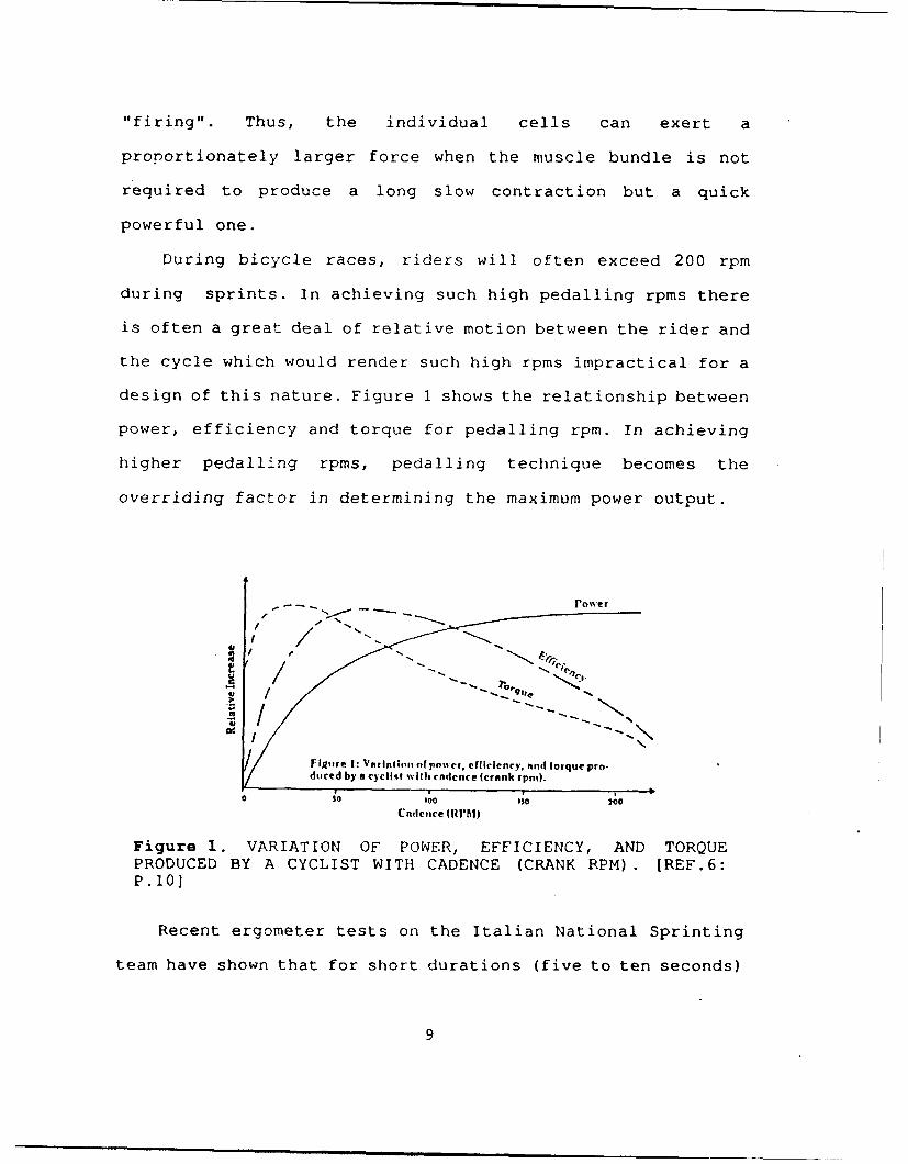
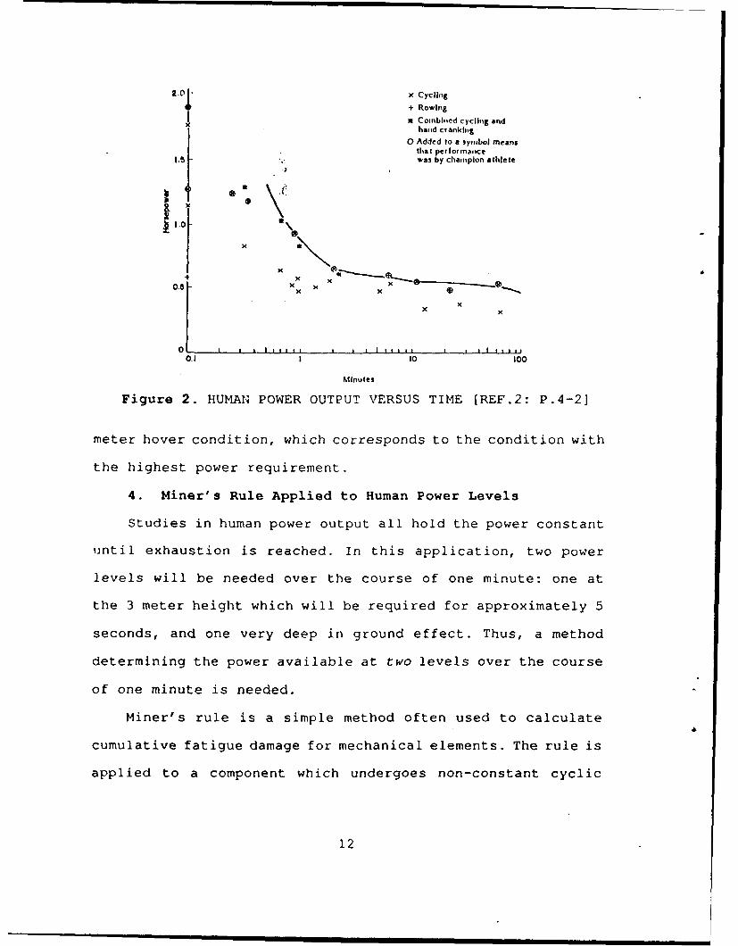
3. Power Versus Time .... ............. 11
4. Miner's Rule Applied to Human Power Levels 12
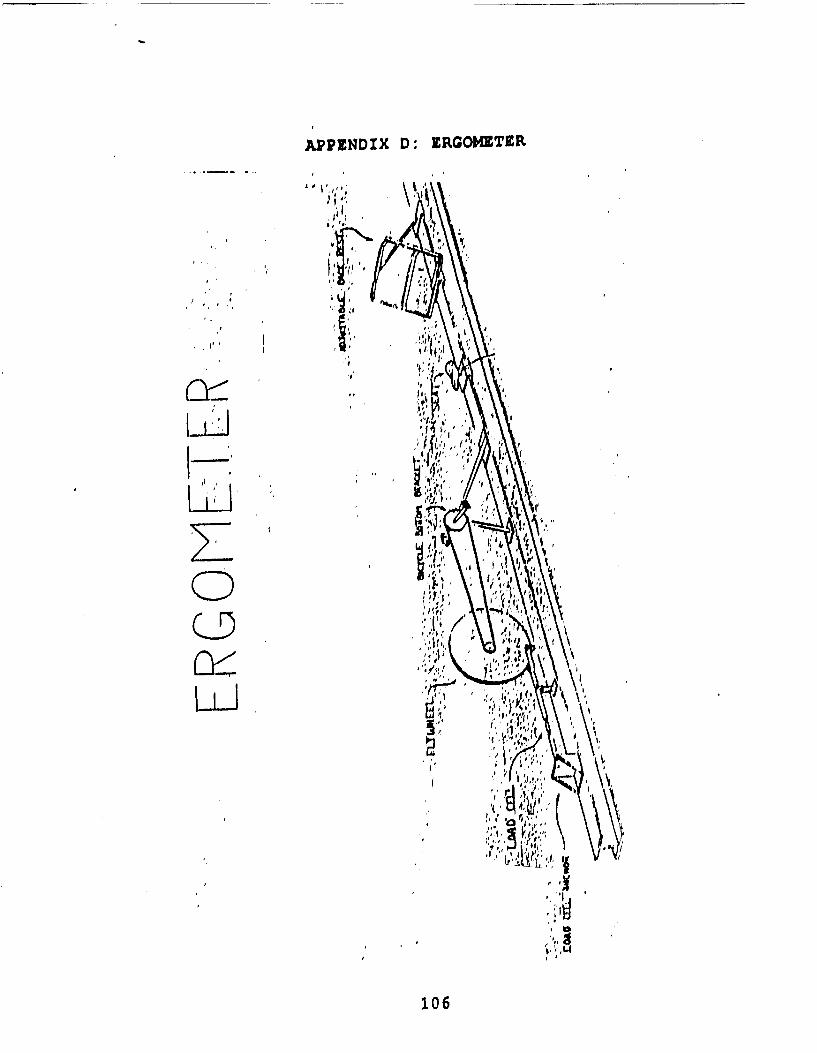
5. Ergometer ...... ................. 15
B. LESSONS LEARNED FROM PAST HUMAN-POWERED
AIRCRAFT ........ ................... .
III. AIRCRAFT DESIGN ...... ................. 20
A. HUMAN-POWERED AIRCRAFT DESIGN THEORY ..... 20
B. ROTOR CONFIGURATION ..... .............. 22
C. AIRFOIL SELECTION ..... ............... 23
iv
1. Preliminary Considerations .. ......... .. 23
2. Airfoil Selection Criteria .. ......... .. 23
3. Low Reynolds Number Airfoil Design Theory 25
a. Reynolds Number Defined . ........ .. 25
b. Drag ...... .................. .. 26
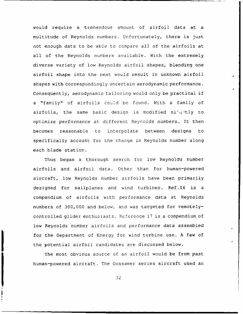
c. Separation Bubble ... ........... . 27
d. Stall Hysteresis .... ............ . 27
e. Wind Tunnel Testing .. .......... .. 28
f. Turbulence ..... ............... .. 29
g. Summary ...... ................. .. 30
4. Final Airfoil Selection .. .......... . 31
D. PLANFORM ....... ................... .. 35
1. Preliminary considerations .. ......... .. 35
2. Rotor Diameter ..... ............... .. 36
3. Twist and Taper .... .............. . 37
4. Tip losses ...... ................. .. 42
IV. PERFORMANCE ....... .................... .. 44
A. HOVER PERFORMANCE ..... ............... .. 44
1. Hover power calculations ... .......... . 44
2. Vortex lattice method ... ........... . 47
3. Approximation accuracy ... ........... . 48
a. Pitch angle equal to the angle of attack 48
b. Inflow on the lower set of rotor blades 50
B. GROUND EFFECT ...... ................. .. 53
1. Theory ....... ................... .. 53
v
2. Ground Effect Calculations .. ......... .. 56
a. 3-meter height .... ............. . 56
b. Deep In Ground Effect .. ......... .. 57
c. Summary of Ground Effect Calculations 57
C. STABILITY AND CONTROL .... ............. . 58
1. Controllability .... .............. . 59
2. Static Stability ..... .............. . 60
3. Lateral and Longitudinal Control ....... .. 62
4. Directional Control ... ............ . 63
5. Collective Control .... ............. . 64
6. Energy Storage ..... ............... .. 64
V. FINAL CONFIGURATION ..... ................ 65
A. CONSTRUCTION ...... ................. .. 67
B. MAIN SPAR DESIGN ..... ............... .. 68
1. Composite Technology Background ...... .. 68
2. Composite Tube Construction . ........ .. 70
3. Composite Material Selection .. ........ .. 70
4. Bending to Torsion Coupling . ........ .. 71
C. ROTOR BLADES ...... ................. .. 72
D. DRIVE TRAIN ...... .................. .. 74
1. Chain/crank system .... ............. . 74
2. Reversing Mechanism ... ............ . 76
E. SUMMARY OF FINAL DESIGN .... ............ . 77
vi
VI. CONCLUSIONS AND RECOMMENDATIONS .. .......... 79
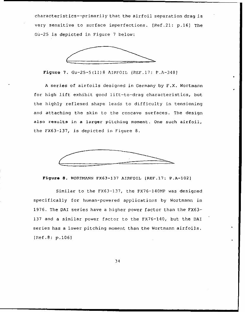
Similar to the FX63-137, the FX76-14OMP was designed
specifically for human-powered applications by Wortmann in
1976. The DAI series have a higher power factor than the FX63-
137 and a similar power factor to the FX76-140, but the DAI
series has a lower pitching moment than the Wortmann airfoils.
[Ref.8: p.1061
34
Selecting the optimum airfoil was not a clear cut
procedure. Power factor data were not available for all
airfoils at the same Reynolds number, and some of the merits
of the particular airfoils had to be accounted for somewhat
subjectively. The airfoils with the best overall
characteristics appears to be the DAI series airfoils. They
have the highest power factor (C.3/2/CD), yet have a low
pitching moment. Being specifically designed for human-powered
aircraft, they are not sensitive to surface imperfections, and
have a satisfactory geometric shape for construction purposes.
They also afford the opportunity to use the family of three
airfoils if necessary. Consequently, the DAI airfoils will be
used for the HPH.
D. PLANFORM
1. Preliminary considerations
The overall goal in designing the rotor blade planform was
to optimize the design for ease of construction and most
efficient lift generation. The ideal rotor blade would
incorporate twist and taper; but the easiest rotor blade to
construct is one with a constant chord. In order to evaluate
the trade-offs between creating the most efficient rotor blade
and one that was easy to construct, it was first necessary to
determine the variable parameters for rotor blade design. The
advantages of each parameter were then balanced against the
disadvantages arising from construction requirements.
35
2. Rotor Diameter
Many human-powered aircraft have had rotor diameters or
wing spans determined not by some critical design parameter
but by some arbitrary physical constraint such as the width of
the hangar it was stored in, or the size of the gym where it
was flown! So it follows with this design. The rotor blade
length (rotor radius) was initially held fixed at 36 feet,
giving the rotor an overall diameter of 72 feet. Arrived at
heuristically, this number represented a compromise between
length, construction and ease of finding a location for
flight. Most importantly, it was approximately the size that
Grohsmeyer, et al. concluded with as their design radius
[Ref.9].
The 36-foot radius represented a number which was known to
be roughly optimum that could be held constant, while all of
the other design parameters could be varied. After the design
was completed, the performance for a 36-foot rotor radius was
very reasonable, so the 36-foot radius was retained as the
design radius.
Holding the initial radius constant did not unreasonably
constrain the design, as the rotor tips will be designed to be
easily modified. It will be easy to add an extension on to the
rotor blade if more planform area is needed, or to modify the
tip shape. Obviously, it would be easy to shorten the rotor
blade should it prove necessary.
36
3. Twist and Taper
The ideal rotor blade for a hovering helicopter has
uniform inflow over the rotor disk, with each section of the
rotor blade operating at a constant angle of attack. In
addition, profile losses will be minimized if the section is
operating at the optimum angle of attack. [Ref.22: p.99] . Hence
the section will be designed to operate at the maximum power
factor (CL /CD) • In achieving the optimum angle of attack for
a hovering helicopter rotor, blade twist and taper (or a
combination) may be used to optimize the blade.
Ideal taper for a rotor blade assumes a uniform induced
velocity and a constant blade pitch angle. Ideal taper for a
four-bladed rotor is shown in Figure 9. The equation for ideal
taper is - ctip (5)z/R
where: c = chord
c tip = tip chord
r = local radius
R = rotor radius
Source:[Ref.22: p.46]
Ideal twist for a conventional hovering helicopter is
G + V (6)nR
where: 0 = blade pitch angle
a= local angle of attack
v = induced velocity
37
Figure 9. ROTOR WITH IDEAL TAPER [REF.23: P.47]
!= rotor speed
r = local rotor radius
Source: [Ref.17: p.46]
Ideal twist also assumes uniform induced velocity. A graph
of ideal twist for constant chord blades and for ideally
tapered blades is presented in Figure 10.
To get a feel for the magnitude of the effects of taper
and twist, Table 1 is presented for a, rotor of solidity equal
to 0.040 for two torque coefficients (C.) .
The above results are valid for a rotor solidity of 0.042
to 0.060. It is noteworthy that a linearly twisted and tapered
blade is only 2 percent less efficient than an optimum rotor.
The optimum rotor is based upon a uniform induced velocity,
and an ideal geometry which is impractical and unrealistic for
a two-bladed rotor. The apparently small benefit from an
38
22.
Constanl Cno'd
Is - Owes
16
Id@&?lY lade'ed
0 .1 .2 .1 4 ~ 7 .6 16 10Rao'.&ulawion. v.R
Figure 10. IDEAL TWIST FOR BLADES WITH CONSTANT CHORD ANDBLADES WITH IDEAL TAPER [REF.23: P.471
ideally tapered and twisted rotor is not an adequate tradeoff
for a blade that will be sign'ificantly more complicated to
construct.
Table 1. PERCENT INCREASE IN4 THRUST FROM UNIWtISTED AND
UNTAPERED BLADE FOR C,=0.00026 to 0.00044 (Ref.16: p.97)
Blade Twist JBlade Taper IThrust Increase1(degrees) Rat io (percent)I
0 3 0
-8 13 5
-12 3 5
Ideal O1)Li mum 7
In considering the degree to which twist and taper will
complicate the rotor blade construction, twist will have the
most significant contribution toward complicating the
39
construction. In making a flat blade it will be easy to lay
out the ribs and spar on a flat surface. Having twist will
require a different pitch angle for each rib and make laying
out, constructing and storing the blade difficult. Hence, the
decision was made to investigate designing a blade with taper
and no twist.
It can be shown that different blade geometries can be
modified to create the same induced velocity profile [Ref.24:
p.69] . Thus, taper and twist are interchangeable to create the
same blade loading. Twist and planform are interrelated by
inflow angle, rotor blade pitch angle and chord, and azimuth.
Since this is a point-design for hover, the inflow will be
polarly symmetric and there will not be any azimuthal
dependency between twist and planform.
It can be shown that little difference exists between a
full linearly tapered rotor blade and a blade that is
partially linearly tapered over the outboard half [Ref.22:
p.971. Since the outboard sections of the blade contain the
majority of lifting surface, this result makes intuitive
sense. Therefore, it was decided to use a partially tapered
rotor blade.
It was also noted that if the taper were designed
effectively, the Reynolds number could be held close over the
outboard section. This represented a different approach to
designing blades. A quick estimation of induced velocities
revealed velocities on the order of 2 to 3 feet per second.
40
This would compare to induced velocities on the order of 35
feet per second for a large conventional helicopter. A
hovering conventional rotor has roughly an 8% to 12% increase
in power-required due to an increase in induced drag as a
result of nonuniform inflow [Ref.25: p.61]. However, with such
low induced velocities it was assumed that the losses from a
less-than-optimum inflow distribution would be minimal.
Tailoring the rotor blade local chord-Reynolds-number to
optimize local airfoil performance might bring sufficient
performance returns to offset the loss in efficiency from a
non-ideal induced velocity profile.
Designing the rotor blade so that the local Reynolds
number remains nearly constant would allow use of one airfoil
over the entire rotor blade and simplify construction. As the
Daedalus airfoils represented the best overall airfoil
available , it was desired to center the Reynolds number
around one of those airfoils' design Reynolds number (250,000,
375,000, or 500,000).
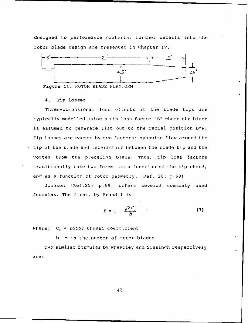
After considerable experimentation, the planform shown in
Figure 11 was arrived at. The planform represents the geometry
that gives the lowest power-required to generate 250 lb of
thrust out-of-ground-effect (OGE), and maintains the Reynolds
number within 86,000 of 500,000 along the outer half of the
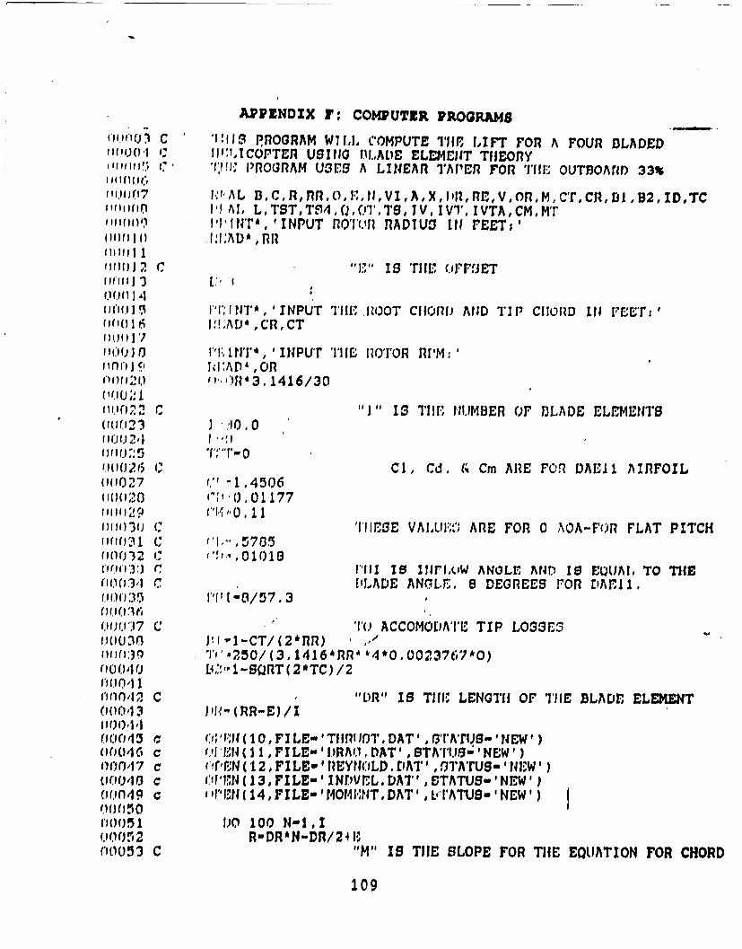
blade. The Fortran program used to compute the hover
performance is presented in Appendix F and will be referred to
as the Performance Program. As the rotor blade design was
41
designed to performance criteria, further details into the
rotor blade design are presented in Chapter IV.
bV 12
4 ~T
Figure 11. ROTOR BLADE PLANFORM
4. Tip losses
Three-dimensional loss effects at the blade tips are
typically modelled using a tip loss factor "B" where the blade
is assumed to generate lift out to the radial position B*R.
Tip losses are caused by two factors: spanwise flow around the
tip of the blade and interaction between the blade tip and the
vortex from the preceding blade. Thus, tip loss factors
traditionally take two forms: as a function of the tip chord,
and as a function of rotor geometry. [Ref. 26: p.69]
Johnson [Ref.25: p.59] offers several commonly used
formulas. The first, by Prandtl is:
B = 1 - V2 (7)b
where: CT = rotor thrust coefficient
b is the number of rotor blades
Two similar formulas by Wheatley and Sissingh respectively
are:
42
B = 1 - Ccip(8
2R
and,
B : 1 - (9)
3R
Tip loss is proportional to the strength of the trailing
tip vortex. The tip vortex results from roll-up of the
trailing vortex sheet into a tip vortex. The trailing vortices
are proportional to the rate of change of bound circulation
(dF/dr) [Ref.25: p.76] . Since the bound circulation for a
blade of a conventional helicopter is much higher than this
HPH rotor blade (which is of comparable size), and dF/dr is
much smaller than for a conventional helicopter, it is
expected that the tip losses will be smaller than might be
calculated by any of the above means. In order to be
conservative, the blade tip loss factor by Prandtl was used.
It still has been proven to be an accurate tip loss factor,
yet it gave the least amount of tip loss.
4 3
IV. PERFORMANCE
A. HOVER PERFORMANCE
1. Hover power calculations
Several fundamental assumptions were made in the initial
performance calculations. During the initial phases of design,
sizing and performance estimates, hover power calculations
were made for the 3-meter height hover condition. This was
considered to be out of ground effect. This assumption was
made due to the low disk loadina of the HPH rotor. In normal
practice, out of ground effect is taken at a one rotor-
diameter height. Typically, graphs generally indicate that
ground effect would provide significant benefit on hover
performance. In this case, the extremely low induced
velocities were assumed to negate ground benefit. This also
represented a worst case scenario and yielded conservative
estimates.
The rotor speed is slow enough that it was assumed that
the inflow from the preceeding blade will have decayed to a
negiigible magnitude by the time the trailing blade arrives.
Thus, the pitch angle was deemed equal to the angle of attack.
The influence of the inflow from the upper blade will cause a
momentary reduction in the angle of attack as it passes over
the lower blade. However, for the sake of simplicity in the
44
initial design, inflow on the lower blades was neglected. The
validity of these assumptions will be evaluated later.
Initial hover power estimates were from the Performance
Program which makes use of blade element theory. The program
assumes a linear taper over the outer one-third of the blade
and constant chord over the rest of the blade with a 3-foot
offset. The program also calculates two tip loss factors (B)
and uses the larger one (least amount of tip losses) . User
inputs are rotor radius, root chord, tip chord and rotor RPM.
Program output is blade station, chord, and Reynolds number
into a data file, "Reynold. Dat." Thrust, in-plane drag and
induced velocity versus blade station are input into files
"Thrust.dat", "Drag.dat" and "Indvel.dat", respectively, for
plotting.
The tip loss factor generated by the program for the final
configuration was 0.965, yielding an effective blade length of
34.74 feet. The rotor blade was divided into 30 sections of
1.2 feet each so that the outboard section corresponded to the
length of rotor blade which was truncated.
The final blade geometry selected was:
0 Rotor radius - 36 ft
0 Root chord - 4.5 ft
0 Tip chord - 2.5 ft
* Rotor speed - 8 rpm
45
The rotor blade design was based primarily on two
criteria: keeping the chord Reynolds number fairly constant
over the outer half of the blade, and the minimum diameter to
keep the power at or below 1.5 hp. The goal during the design
process was to keep the chord Reynolds number within +/-
100,000 over the outer half of the rotor blade, enabling the
use of one airfoil. The final design keeps the Reynolds number
within 86,000 of 500,000 (which is the design Reynolds number
of the DAE 11 airfoil). A table of data showing the Reynolds
number versus the blade station is presented in Table B-l,
Appendix B.
The rotor blade configuration above results in the
following performance:
" Total thrust - 250 lb
" Power required - 1.53 hp
* Tip speed - 30.5 fps
* Tip loss factor - 0.965
The tip loss factor closely correlates with that used for
conventional helicopters which is often taken to be a constant
0.97. The taper ratio was used primarily to keep the Reynolds
number as constant as possible. Of all of the rotor blade
parameters, the rotor radius has the single greatest effect on
aircraft performance. Several rotor radii are presented in
Table II to get a feel for the relationship between radius and
horsepower required to generate 250 lb of thrust for a blade
46
with the same relative geometry (1.8:1 linear taper over the
outboard 33%) . It can be seen that the relationship between
rotor radius and power required is linear at 0.0167 hp/ft.
Table II. POWER REQUIRED TOGENERATE 250 LBS OF THRUST FORVARIOUS ROTOR RADII.
ROTOR RADIUS POWER(ft) (hp)
28 1.74
32 1.63
36 1.53
42 1.43
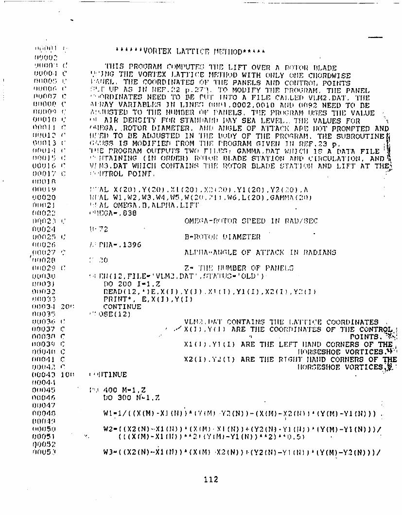
2. Vortex lattice method
The vortex lattice method (VLM) described in (Ref.28:
p.271] was used to calculate the lift over the rotor blade.
Only one chordwise horseshoe-vortex was used. The Fortran
program used is presented in Appendix F. The vortex
distribution is presented in Figure A-i, Appendix A. The same
basic airflow assumptions as for the blade el ment program
were made in the vortex lattice program. The final geometry
from the blade element method was used and a total lift of 71
lb per blade (284 lb total) was calculated. This represented
an 11% increase in lift over the blade element method. The VLM
lift distribution is plotted along with the blade element
4'
method in Figure A-2, Appendix A. A table of circulation
versus blade stations is presented in Table B-2, Appendix B.
The VLM is presented as a separate method to verify the
results of the blade element method. The VLM method is assumed
to be less accurate and is not used for primary performance
calculations. However, the lift distribution is much more
accurate and will be useful for structural considerations.
3. Approximation accuracy
a. Pitch angle equal to the angle of attack
This section will make some simple flow models and
estimate the degree to which some of the basic assumptions
were valid. The assumption was made that the pitch angle was
equal to the angle of attack. This implied that the induced
velocity of the leading rotor blade will decay to
approximately zero before the next blade arrives at that
azimuthal position. Or, from another perspective, this
assumption says that each blade is moving into "clean air,"
that is, air undisturbed from the previous blade. To estimate
the validity of the assumption, assume that the trailing
streamlines are that of flow over a rotating cylinder where
the diameter is equal to the chord. The equation for the
radial velocity around a cylinder is given by:
48
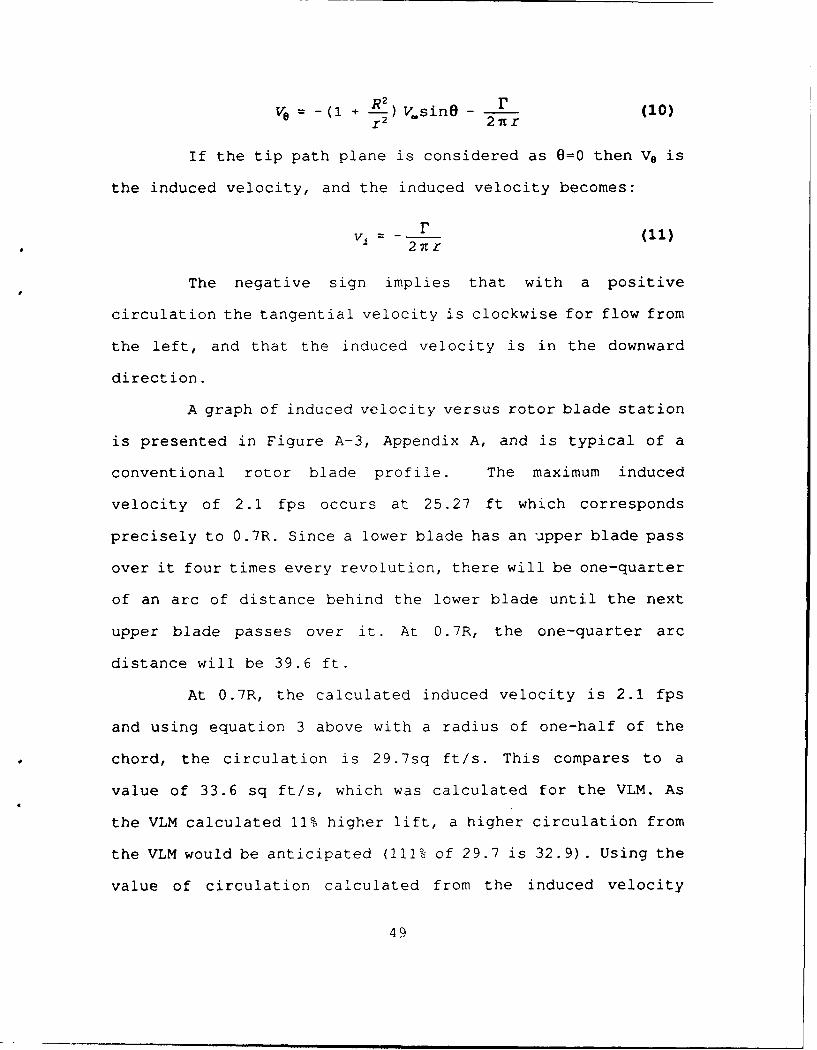
e -(1 + R2 ) V.sinO r 1
r 2 2 Tcr (0
If the tip path plane is considered as 0=0 then Ve is
the induced velocity, and the induced velocity becomes:
V r
The negative sign implies that with a positive
circulation the tangential velocity is clockwise for flow from
the left, and that the induced velocity is in the downward
direction.
A graph of induced velocity versus rotor blade station
is presented in Figure A-3, Appendix A, and is typical of a
conventional rotor blade profile. The maximum induced
velocity of 2.1 fps occurs at 25.27 ft which corresponds
precisely to 0.7R. Since a lower blade has an upper blade pass
over it four times every revolution, there will be one-quarter
of an arc of distance behind the lower blade until the next
upper blade passes over it. At 0.7R, the one-quarter arc
distance will be 39.6 ft.
At 0.7R, the calculated induced velocity is 2.1 fps
and using equation 3 above with a radius of one-half of the
chord, the circulation is 29.7sq ft/s. This compares to a
value of 33.6 sq ft/s, which was calculated for the VLM. As
the VLM calculated 11% higher lift, a higher circulation from
the VLM would be anticipated (111% of 29.7 is 32.9). Using the
value of circulation calculated from the induced velocity
49
(F=29.7 sqft/sec.), at 79.2 ft behind the blade (two times the
quarter-arc distance of 39.6 ft) the induced velocity (vi)
becomes 0.060 ft/sec when the next blade passes under it. The
inflow angle becomes:
4)t= 0.16degrees (12)
The rotor blade pitch angle can be trimmed to operate at
an average angle of attack closest to the optimum power factor
so the induced velocity will not adversely affect the lift
generated. Rather, it will mean that the blade will be tilted
aft slightly (0.16 ), increasing the component of the lift
vector in the in-plane (drag) direction. This calculation is
based on the largest induced velocity and is small enough to
be considered insignificant with respect to the anticipated
torsional flexibility of the rotor blades.
b. Inflow on the lower set of rotor blades
To obtain an estimate of the effect of the previously
neglected inflow of the upper rotor on the lower rotor blades,
several simple approximations will be made based on the
induced velocity of the upper set of rotors. The results will
then be applied to the performance program and compared to the
originally calculated performance.
Induced air flow passes through the tip path plane at
an induced velocity of v,. The flow necks down and the inflow
increases to 2v, at one rotor-diameter below the tip path
50
plane. The lower set of rotors will be as close as possible
below the upper set of rotors, so the increase in induced
velocity due to the necking down will be assumed to be
negligible.
At 0.7R, where the highest induced velocity is
located, a rotor blade passing below this blade will be
momentarily subject to an inflow angle corresponding to:
4)= tan-l vi = 5.7degrees (13)
which will effectively reduce the angle of attack by that
amount.
To get a feel for the added power required due to the
inflow from the upper rotors, a simple flow model is
generated, the increase in pitch angle to overcome the inflow
is calculated, and the value of that increased pitch angle is
put into the performance program to provide an estimate of the
additional power required.
Assume that as the leading edge of the rotor blade
passes over the lower blade the effective induced velocity
increases exponentially according to:
V1 (x) = v. (I - e -x) (14)
until the full induced velocity is reached at the trailing
edge of the airfoil. This is an assumption based on the
induced velocity buildup for a suddenly applied angle of
attack on an airfoil [Ref.29: p.4]. After the trailing edge
51
passes the lower rotor blade, the induced velocity decreases
according to that of a cylinder of diameter equal to the
chord. The complete formula to calculate the induced velocity
becomes:
v. (x) = v. (I - e -x) 0x!c (15)
v.(x) r cx_.39 .6 (16)
Integrating over the entire quarter of arc and
dividing by the length of the arc to find the average induced
velocity yields:
V = 0.416fps (17)
Using equation 13, the average inflow angle becomes:
%v = 1.661 degrees (18)
Again, this implies that the lower set of blades will
have to have the pitch angle increased 1.61 degrees to operate
at the same average angle of attack. Adding the increased
inflow angle to the pitch angle will tilt the lift vector
further aft resulting in a higher in-plane drag. Adding the
increased inflow angle to phi in line 84 of the performance
calculation program will increase the pitch angle on all four
blades. With phi equal to 1.68 radians, the program calculates
an increase in power required from 1.53 hp to 1.82 hp. Since
only half of the blades will show an increase, the average of
the two results in a power required to hover of 1.68 hp. This
52
m m u l ! m I M
represents an increase in power required of 0.15 hp, or a 10%
increase.
A power increase of 10% represents a noteworthy
increase. However, it will be seen that it is not too
significant when compared to the variables associated with
ground effect.
B. GROUND EFFECT
1. Theory
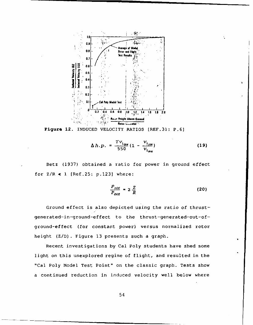
Ground effect is defined as a reduction in induced power
due to proximity of the ground. It is characterized by a
reduction in induced velocity required to produce a given
thrust. A plot showing induced velocity ratio as a function of
normalized rotor height is presented in Figure 12.Since the
induced velocity is reduced in ground effect for the same
thrust generated, the blade can operate with the same angle of
attack at lower pitch angles. The reduction of pitch angle
results in less rearward tilt of the lift vector, and
consequently a reduction in the induced power from that
required out of ground effect. Height above the ground is
typically referred to as Z/D, where Z is the rotor height and
D is the rotor diameter.
The difference in power required due to ground effect
becomes:
Where: v,=induced velocity
Source: [Ref.25: p.67]
53
l.0-
0. Avo ogo of Model09- Roto, and Fight
- Test Rle.Wl1 ,
0.7
9g 0.6
0 25 ., . 4 1' :" 0.2 - F''
• . . +..
0 ' 01 -/ CalPoly ModelTest ;i '
ROem L.,A1sr '.
Figure 12. INDUCED VELOCITY RATIOS [REF.31: P.6]
Tv VAh.p. - Tv ,(1 - v 1 - (19)
550 v 1 00
Betz (1937) obtained a ratio for power in ground effect
for Z/R < 1 [Ref.25: p.1231 where:
P___ = 2 Z (20)POOE R
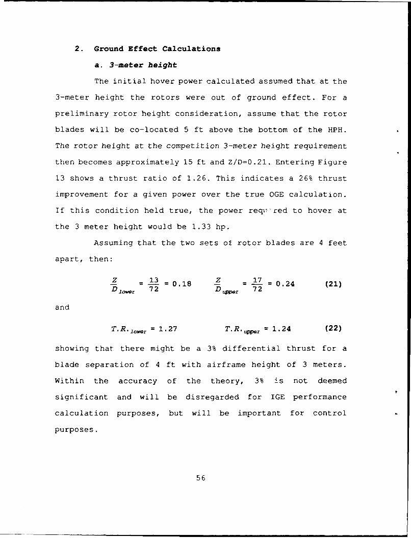
Ground effect is also depicted using the ratio of thrust-
generated-in-ground-effect to the thrust-generated-out-of-
ground-effect (for constant power) versus normalized rotor
height (Z/D). Figure 13 presents such a graph.
Recent investigations by Cal Poly students have shed some
light on this unexplored regime of flight, and resulted in the
"Cal Poly Model Test Point" on the classic graph. Tests show
a continued reduction in induced velocity well below where
54
1.40
1.35-
1.30-i1 1.25
U (U 1.20
115
1.10-
1.05
0 0,2 04 0.6 0.8 1.0 1.2 14 16 18 2.0
Rotor Height Above GroundRotor Diameter
Figure 13. THRUST FOR SAME POWER [REF.31: P.5]
most graphs and data go. This is shown on Figure 12, above.
This implies that at very small Z/D, rotor drag becomes
primarily profile drag.
Interestingly, tests at Cal Poly by Baker and Scarcello
show increased ground effect over rough surfaces. Hence, when
the Cal Poly team was attempting to achieve the world's first
human-powered helicopter hover, they put relatively large
cardboard fences on the floor in an attempt to increase the
"surface roughness" of the gym floor and take advantage of
this surface roughness effect. [Ref.28: p.61
With the exception of recent studies at Cal Poly, there
has been little, if any, research on helicopter rotors deep in
ground effect. The standard configuration of most helicopters
places the rotor already at Z/D of roughly 0.2 when sitting on
the ground. This has probably obviated the need for studies of
ground effect below that Z/D.
55
2. Ground Effect Calculations
a. 3-meter height
The initial hover power calculated assumed that at the
3-meter height the rotors were out of ground effect. For a
preliminary rotor height consideration, assume that the rotor
blades will be co-located 5 ft above the bottom of the HPH.
The rotor height at the competition 3-meter height requirement
then becomes approximately 15 ft and Z/D=0.21. Entering Figure
13 shows a thrust ratio of 1.26. This indicates a 26% thrust
improvement for a given power over the true OGE calculation.
If this condition held true, the power requesred to hover at
the 3 meter height would be 1.33 hp.
Assuming that the two sets of rotor blades are 4 feet
apart, then:
Z 13 =0.18 Z 17 0.24 (21)D lower 72 Duper 72
and
T.R. ow= 1.27 T. R. r 1.24 (22)
showing that there might be a 3% differential thrust for a
blade separation of 4 ft with airframe height of 3 meters.
Within the accuracy of the theory, 3% is not deemed
significant and will be disregarded for IGE performance
calculation purposes, but will be important for control
purposes.
56
Entering Figure 12 with Z/D of 0.21 gives a value of
the induced velocity ratio of 0.7. Equation 19 assumes that
the induced velocity is constant over the blade, so the
average induced velocity generated from the Performance
Program will be used to calculate ground effect. Using average
induced velocity of 1.67 fps, the Ahp is 0.23 hp, and the
power required to hover IGE becomes 1.30 hp.
b. Deep In Ground Effect
Using Betz's formula with the true OGE hover power
calculation and the added induced power on the lower set of
blades:
PIGs = (PGE) 2 = (1 . 68) (2 - ) = O.56hp (23)' E' R '' 72
Using:
Z 6 0833 (24)D 72
the hover situation approximates the "Cal Poly Point" on
Figure 12. The ratio of induced velocities is 0.05. Using the
average induced velocity (provided by the Performance Program)
of 1.67 fps, the ho is 0.72 hp; making the power-required to
hover IGE 0.80 hp.
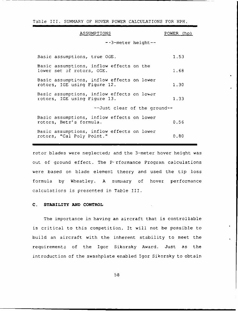
c. Summary of Ground Effect Calculations
The basic assumptions made in calculating hover power
were: the inflow from a rotor blade will have decayed to zero
at the trailing blade; inflow effects on the lower set of
57
Table III. SUMMARY OF HOVER POWER CALCULATIONS FOR HPH.
ASSUMPTIONS POWER (hp)
--3-meter height--
Basic assumptions, true OGE. 1.53
Basic assumptions, inflow effects on thelower set of rotors, OGE. 1.68
Basic assumptions, inflow effects on lowerrotors, IGE using Figure 12. 1.30
Basic assumptions, inflow effects on lowerrotors, IGE using Figure 13. 1.33
--Just clear of the ground--
Basic assumptions, inflow effects on lowerrotors, Betz's formula. 0.56
Basic assumptions, inflow effects on lowerrotors, "Cal Poly Point." 0.80
rotor blades were neglected; and the 3-meter hover height was
out of ground effect. The P-rformance Program calculations
were based on blade element theory and used the tip loss
formula by Wheatley. A summ~ary of hover performance
calculations is presented in Table III.
C. STABILITY AND CONTROL
The importance in having an aircraft that is controllable
is critical to this competition. It will not be possible to
build an aircraft with the inherent stability to meet the
requirements of the Igor Sikorsky Award. Just as the
introduction of the swashplate enabled Igor Sikorsky to obtain
58
satisfactory control and achieve the first truly successful
powered flight of the VS-300 helicopter in 1939, the "control
problem" must be accounted for in the HPH design. As was seen
in the introduction, it was controllability that allowed the
Gossamer Condor to become the "first" human-powered aircraft.
In their case, the unstable nature of their design was not a
problem, as the controllability characteristics were such that
the pilot could easily maintain steady flight. During the Da
Vinci's 7-second world-record flight, it appears that the
pilot could have easily flown longer, but the aircraft was
becoming increasingly unstable and in imminent danger of
crashing. A controllable aircraft is paramount to a successful
human-powered hover, and winning the Igor Sikorsky Award.
1. Controllability
"Controllability may be defined as the capability of thehelicopter to perform, at the pilot's desire, anymaneuvering required in a particular mission. Thecharacteristics of the airplane should be such that thesemaneuvers can be made precisely and simply with a minimumof pilot effort. [Ref.32: p.2-2]"
In this case the "mission" is to maintain a hover within
the prescribed area and maintain a constant heading for one
minute. It can be seen from this definition of
controllability, that if the aircraft is unstable but easily
controllable, the flying qualities could still be satisfactory
for the mission. Today's powered helicopter (without automatic
stabilization) is in this control category.
59
2. Static Stability
An aircraft is statically stable if it tends to return
toward its original trimmed condition when disturbed from an
equilibrium condition [Ref.32: p.3-3]. An aircraft is
dynamically stable if it returns to an equilibrium condition
on its own if disturbed from trim [Ref.32: p.3-4]. Both
definitions are open-loop conditions, whereby the controls are
left in the trimmed position and the pilot does not make any
inputs to correct the aircraft attitude.
An aircraft can be statically stable but dynamically
unstable. An example would be an oscillatory motion of
increasing amplitude called "oscillatory divergent". It tends
toward returning to trim but overshoots by an increasing
amplitude each cycle. To be dynamically stable, the aircraft
must be statically stable.
Positive damping is that characteristic of a system which
opposes transient motions and results in decreasing cyclic
amplitudes (for oscillatory motion) or decreases a rate of
motion (Ref.32: p.3-5]. Negative damping is unstable.
Classically, a damping force or moment is proportional to
velocity, and in some non-linear cases to (velocity)2. Hence,
roll damping is the moment which opposes a roll rate and
causes the aircraft to stop rolling once the controls are
returned to neutral.
Light, large aircraft such as human-powered aircraft have
low inertia and very high damping compared to conventional
60
aircraft. The pitch damping of the Gossamer aircraft was high
enough that the maximum rates that could be developed (if
allowed to diverge) were so small that they were easily
compensated for by the pilot. If an aircraft is unstable, it
is important that adequate control margin is available to be
able to control the aircraft.
Associated with unsteady aerodynamics, there is an inertia
force referred to as "apparent mass." When accelerating a wing
perpendicular to its direction of motion, it is necessary to
accelerate not only the wing itself but the air surrounding
the wing as well. For a high aspect ratio -ng, the apparent
mass is equal to the mass of a cylinder of air with a diameter
equal to the local chord. For the rotor blade design proposed:
c 2 1 2 c P) 2]
AM = n (--L-) (24) Pair + -2 [--'2- +(- -2 - - (12) Pair = 38.81b
Each rotor blade weighs approximately 20 lb. Thus, the
apparent mass nearly doubles the inertia of the rotor blade.
Despite the increased inertia, Drela [Ref.8: p.104] showed
that roll damping still dominates the roll response in human
powered aircraft.
A generic helicopter in a hover will be statically stable
with regard to translational velocity [Ref.22: p.283]. That
is, if the trimmed hovering aircraft is displaced in roll it
will not generate a restoring moment until a translational
velocity is developed which causes blowback which generates a
restoring moment. If allowed to continue unchecked in a
61
conventional helicopter, the motion results in a dynamically
unstable oscillatory divergence [Ref.23: p.6031 . In a HPH, the
pitch and roll damping are so high that large rates cannot
build up. It is anticipated from dimensional considerations
that this HPH will be statically stable as well. If allowed to
start, an oscillation in pitch or roll would be of limited
amplitude due to the limited pitch/roll rates. However, the
aircraft would tend to "slide" sideways into the ground. As
such, it will be imperative that a control system be
implemented to keep lateral and longitudinal translational
velocities to zero.
3. Lateral and Longitudinal Control
It is proposed that a side force generator rather than a
roll moment generator be used to control the HPH. The basis
for this proposal is the trouble exhibited by past human-
powered aircraft in roll control. There will be very little
difference between roll and pitch for this aircraft, so "roll"
will be used to imply either pitch or roll. The wings of past
human-powered aircraft have been so flexible that conventional
aileron control has been ineffective. For turns, the Gossamer
series used a canard as a yaw force generator to generate
differential wing lift and consequently a roll moment. The
Daedalus team was unable to make an effective aileron system
so they used the rudder and the dihedral effect to make
shallow turns.
62
Rotor blade winglets on the upper set of blades are
proposed as the means of generating a side force. By
cyclically varying the angle of incidence of the winglets a
side force can be generated and used to control position over
the ground. If designed correctly, winglets may also have the
added benefit of reducing tip losses.
4. Directional Control
Heading control will also be necessary to win the
competition. Torque differentials between two rotor blades
caused by inflows, non-linear ground effects, and winglet
inputs will cause the pilot to rotate with reference to the
ground. Conventional heading control for counter-rotating
rotors is by differential collective inputs to the two rotors.
Heading control for this HPH is proposed by changing the
torque on the upper rotor only. This can be performed by
changing the total lift on the upper rotor. The rotors can be
finely tuned so as to be in torque balance for one flight
condition, thus requiring only small inputs to maintain
heading as hover conditions vary. Lift change on the upper
rotor can be accomplished by either a small flap-type control
or by blade pitch change.
The co-axial design has an inherent stability advantage
over a two-bladed helicopter in that it has polar moment of
inertia symmetry between X and Y axes. For the Da Vinci,
Ix30Iyy. The extremely small moment of inertia about the
63
feathering axis resulted in the helicopter pitching about the
main spar (feathering axis) and falling over.
5. Collective Control
The most simple means of controlling thrust (for height
control) is by varying rotor speed. It has the advantage of
eliminating mechanisms required to feather the blades and
thereby reducing total airframe weight. Some radio-controlled
helicopter models have been very successful in using this
technique to eliminate the conventional collective control.
6. Energy Storage
An investigation was made into using the inertia of the
rotor blades to store energy. If a system were derived whereby
the blades could be held at the zero lift angle of attack, the
blades could be accelerated to above the design speed and the
energy in the rotor inertia could be used to help lift the
aircraft to the 3-meter height immediately after takeoff.
Considering only the inertia of the rotor blades, the total
inertia is the sum of the two sets of blades where the blades
are assumed to have uniform mass distribution. The moment of
inertia of a long uniform rod rotating about the middle is:
1 2 (26)- 12
where for this case: m = 40 lb
1 = 72 ft
and
64
In,= 17,820 lb-ft 2 (27)
The energy required to lift 250 lb to 3 meters is:
P.E. = mgh = 80,500 ftA-lb (28)S
2
The kinetic energy in the rotor system is:
K.E. = (2) 1II,,2 = 12,514 ft 2 -lb (29)
2 s2
Assuming the rotor blades will need to be at the design
operating rpm at the top of the climb, the total energy needed
to be stored in rotor inertia at flat pitch is the sum of the
potential energy required to climb to 3 meters and the kinetic
energy of the rotors at the design condition. The total energy
required at flat pitch is:
Etota= 93,014 ft 2 - 1 b (30)s 2
Solving for the rotor speed required at flat pitch:
=2.18 =ad = 20.8 RPM (31)sec
This would present a problem in that the pilot would be
required to pedal at 234 rpm (without any variable gear
ratio), an unrealistic speed.
If the maximum flat pitch rotor rpm were limited by
profile drag, and a limit of 1 hp were set, then a maximum
rotor speed could be calculated using the Performance Program.
Unfortunately, airfoil data are only available to 0 degrees
65
angle of attack (as opposed to the zero-lift angle of attack)
The program gives 9.3 rpm at 1 hp; but 125 lb of thrust is
still being generated. Regardless, it will not be possible to
achieve a rotor speed of 20.8 rpm!
For argument sake, it will be assumed that a rotor speed
of 12 rpm would be able to be generated by placing the rotors
at the zero-lift angle of attack. Then, by increasing the
blades' inertia using tip weights it wuuld still be possible
to achieve the added energy at minimum pitch. Solving for the
weight necessary to do this results in 34 lb. tip weights--
obviously an unrealistic proposition as the power required to
hover deep in ground effect with the extra 132 lbs is well
above human power capabilities.
In conclusion, the high rotor blade profile drag prevents
a high minimum-pitch rotor speed and precludes any effective
use of the rotors as a means for storing energy. There would
be no advantage in adding tip weights, and no reason to add
the capability to feather the rotor blades for energy storage
purposes.
66
V. FINAL CONFIGURATION
A. CONSTRUCTION
The design of an HPH is a relatively simple operation
compared with monumental task of building the HPH.
Construction will command an extraordinary amount of manhours,
require innovative thinking and use of materials not normally
used in the aerospace industry. It may be possible to make use
of some of the local high school or college students to help
construct the aircraft in exchange for science credits. In the
attempt to construct a light, strong aircraft, past teams have
required a large amount of trial and error in construction
techniques. Mr. P. Zwann, builder of two (unhoverable but not
unsuccessful) human-powered helicopters, said that probably
the best advice he could give was to "...sketch with your
materials. [Ref.33]"
As in all arenas of scientific endeavors, progress is made
by building upon others' past discoveries, research and
development. Through exhaustive research it is hoped that the
lessons of past mistakes of human-powered aircraft designs and
construction will be learned and not repeated here. This
section will discuss some of the construction methods and
materials necessary for construction of this HPH.
67
B. MAIN SPAR DESIGN
1. Composite Technology Background
Composites have been used in aircraft in the form of
plywood since the early days of aviation. Advanced composites
have allowed significant structural advantages for human-
powered aircraft. Good composite design can allow a
significant weight savings over other materials and result in
a stronger and stiffer structure. Furthermore, it is possible
to do much of the composit.e construction at the NPS without
having to resort to a commercial composite outfit. For
example, a gentleman named Juan Cruz (who is now a composite
specialist for NASA) hand built the spars of the Daedalus
aircraft using pre-impregnated unidirectional graphite-epoxy
tape [Ref.2: p.97].
Part of the purpose of this HPH project is to promote
various aspects of aeronautical engineering. The use of fiber
re-inforced composites has been called the biggest technical
revolution in aviation since the jet engine [Ref.34: p. 85,90
and 91] . Composite design and construction is becoming an
integral part of naval aviation, and as such should be
understood by all aeronautical engineers. With some easily
constructed facilities at the NPS, it would be quite possible
to build the rotor blade spars required for this HPH.
To determine the feasibility and reliability of a hand
layed composite section, information from a NASA report
68
regarding cylinders tested in strictly compression is
presented. The report tested HS-4 graphite and 3502 epo..y
cylinders with different lay-ups. Despite only reporting on
compression test samples, there should be no reason that the
quote would not apply to cylinders in combined loading. "A
comparison between filament wound and hand laid-up tape
control cylinders indicates there is little or no difference
in the response of cylinders constructed using the two
manufacturing techniques." [Ref.35]
A composite consists of two or more dissimilar elements
combined on a macroscopic scale to create a material
exhibiting properties that neither has of its own. The
material comprising the composite are termed the
"constituents." For purposes of this paper, the term
"composite" will imply a fibrous composite. A fibrous
composite consists of fibers in a matrix. The fibers are long
and continuous, and can be woven or unidirectional. The matrix
is the substance that binds the fibers together and serves
many purposes; among them to add structural support, transfer
stresses, and to protect the fibers. The composites can be
layered with the fibers in different directions, and the
composite becomes a "laminated fibrous composite." [Ref.36:
p.2-5)
69
2. Composite Tube Construction
Cylindrical composite tubes are created by wrapping the
composite around a form called a "mandrel." Two main methods
are used. Where the facilities are available, tubes are
generally constructed using a technique called "filament
winding." Here, an individual fiber is coated with a matrix
and wound in pre-determined directions, and layers, around a
mandrel. The other method is to use pre-impregnated tape
called "pre-preg" which comes in rolls or sheets and is
wrapped around the mandrel in the same manner as filament
winding. Filament winding is generally used for highly
automated production, and pre-pregs are frequently used for
small batches or one-of-a-kind construction. The composite
shrinks upon curing, and extraction of the mandrel becomes
difficult. A common method is to etch a groove through the
tubular metal mandrel with acid, allowing the mandrel to
compress and be easily extracted.
3. Composite Material Selection
In determining the constituents, several factors need to
be considered: strength-to-weight ratio, stiffness, and
cost/availability.
Graphite represents a strong, stiff and relatively cheap
fiber and is probably the most suitable for construction of
the main spar. Graphite-epoxy pre-preg unidirectional tape
represents the most suitable composite material. In
70
determining the directions of the individual lamina, called
the lay-up, the blade loading will be needed. The thrust and
drag have been previously been presented, but the pitching
moment has not. The moments are generated by the Performance
Program (Appendix F) and the data output to a file
"moment.dat." Note that the pitching moments are negative,
indicating a leading edge down pitching moment.
Much of composite strength and reliability is dependent
upon the manufacturing process. It will be necessary to build
and test specimens in order to refine the design and
fabrication process. The spar is essentially a torque tube
with longitudinal structural re-inforcement on the top and
bottom. The Daedalus used smaller tubes bonded to the top and
bottom as tension and compression members. The Da Vinci used
a lamina running axially (lay-up angle of 0 degrees) on the
top arn bottom to serve the same purpose.
There exists a flat, unidirectional laminate used by
makers of skiis and composite bows that may be suitable as the
spar tube cap. Sold by Gordon Plastics in Vista Ca., it is
called "Spar Tuf" and comes pre-cured and ready to be bonded.
It has been tested in both tension and compressicn to 150,000
psi.[Ref.37: p.9-41
4. Bending to Torsion Coupling
The spar can also be designed to incorporate bending to
torsion coupling. This would have two advantages. The first
71
would be to counter the pitching moment. The second would be
to serve as an effective collective control to increase the
pitch angle as more lift is generated and the blades flex up.
Thus, at low speed, the bladep would be at a reduced angle of
attack and require less torque to accelerate the rotcr system.
As the lift increases, the blades flex up, and the pitch angle
will increase until equilibrium is reached whereby the airfoil
is operating at the design angle of attack. Either a section
at the root can be designed with bending to torsion coupling
so the entire spar twists a constant amount, or the the
coupling can be incorporated into the entire blade, inducing
blade twist. The former is equivalent to the well known delta-
3 hinge built into rotor blades for pitch-flap coupling.
Refinement of the spar design is beyond the scope of this
report and is left for follow-on work. The intent is to show
that design and construction of a graphite-epoxy spar is well
within the capabilities of the NPS.
C. ROTOR BLADES
This paper has used the helicopter terminolc-gy of rotor
blades, when in fact they are more correctly termed "rotary
wings" as strutural rigidity is achieved through a
cantilevered spar rather than from centrifugal forces. The
Cheyenne and ABC helicopters also had cantilevered rotor
blades like this. It gave rise to the term "rigid rotor." That
term was considered incorrect, which led to the term
72
"hingeless rotor." Hence, construction methods will be similar
to wings of past human-powered aircraft. Construction of the
spars was addressed previously and will not be discussed in
this section.
The rotor blades will be constructed using a tubular
composite main spar with lightweight ribs, and covered in a
thin polyester film. Ribs can be fabricated from low density
(2 lb/ft3 ) foam and structural support added as necessary. One
source for sheet foam is Ref.38. The foam ribs can be backed
with paper, or supported with flat composite strips glued to
the sides. The leading edge of the rotor blade should have a
rigid sheet of material wrapped around it to add rigidity to
the skin along the portions of the airfoil with a high (or
low) co-efficient of pressure to prevent excessive airfoil
deformation.
The polyester-film skin can be made of 0.5 mil Mylar
(manufactured by DuPont) which has been used successfully in
past human-powered aircraft. Information on Mylar is provided
in Appendix G.
The rotor blades need to be designed for easy
transportability and set-up. The blade could be designed into
three sections of 12 ft each, with the two inboard sections
all being constant chord. The criterion for spacing of the
ribs is unknown and will probably be a function of the ease of
tensioning and heat shrinking the Mylar. The spacing will most
likely have to be determined after materials can be obtained
73
and a test section constructed. Adhering the film to the ribs
can be easily done using a spray glue made by 3M called Spray
77 [Ref.33].
The support structure for the pilot, termed the
"undercarriage," should also be made from composite tubing for
maximum strength-to-weight ratio. The undercarriage includes
the "landing gear" structure that provides some degree of
protection by absorbing energy during landings and a means for
the aircraft to stand upright.
The mast and rotor blade hubs shall also be fabricated
from composites. Bearing races can be fabricated in the NPS
workshops form metal. The hollow mast will allow control
tubes/cables to pass through to the upper rotor blades. A
scheme to allow pilot azimuthal control of the winglets for
lateral/ longitudinal control needs to be devised in future
design refinements.
D. DRIVE TRAIN
a. . ....nk system
Past histories of human-powered aircraft have shown the
drive train to be a neglected yet crucial element in the
design and development of human-powered aircraft.
Conversations with builders of two human-powel-ed helicopters
have confirmed this conclusion [Ref. 33 and 39]. The
characteristics of a successful HPH drive system are
74
reliability, light weight , ability to withstand high torques,
and simplicity.
Human power studies have shown pedalling to be the
preferred method for this application. Hence, standard bicycle
components should be used as they have several distinct
advantages:
" They are proven to work as intended.
* They come in standard sizes and are easily interchangeableto obtain the optimum system.
" They could most likely be obtained gratis; either fromlocal shops or the manufacturers.
* They can easily be modified (drilled out) to be madelighter.
" Many cyclists (potential pilots!) prefer certain gear(pedals for example) and can be easily interchange theirown gear.
" Chain wheels can be easily changed to alter the main rotordrive gear ratio.
Further work on the ergometer may offer more information
regarding the optimum crank system. In reality it will most
likely be the pilot's choice/preference. The choice to use
conventional bicycle components will offer advantages over
custom designed equipment and should be considered.
The chain will be required to twist 90 degrees to operate
in the same plane as the rotor shaft. A flexible chain is
commercially available [Ref.40: p.A80] which is particularly
suitable. Called POW-R-CHAIN, it has a 1/2 inch pitch and is
compatable with standard bicycle drive gears. Made of
75
polyester rollers fixed to wire cables, it has a tensile
strength of 300 lb and weighs only I ounce per foot.
Large torques are required on start-up, and a drive system
is required to be able to withstand these large forces. The
proposed bicycle crank/chain drive system is proven, simple
and lightweight. The only disadvantage of a chain-drive system
is the requirement for feeder slots for the chain going onto
the gear.
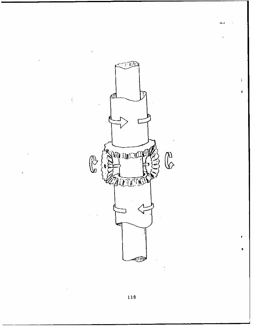
2. Reversing Mechanism
Again, a robust drive system that is simple and
lightweight is desired. The proposed reversing mechanism
effectively combines these elements. A drawing of the
reversing mechanism is presented in Figure H-1, Appendix H.
The rotor mast is centered about a main, stationary mast
to which the undercarriage is fixed. Around this mast are two
identical sleeves each of which serve as the rotor hub. Where
the two sleeves meet, they are interconnected by an idler
wheel. As the bottom sleeve rotates, the idler wheel will turn
the upper sleeve at the same speed, except in the opposite
direction. A bevelled pinion gear and ring gear will
effectively accomplish the intended job. Available from
commercial sources, they will have to be sized upon completion
of the exact drive train design.
76
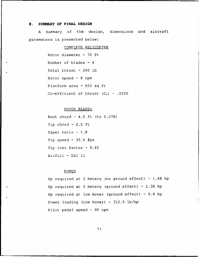
E. SUMMARY OF FINAL DESIGN
A summary of the design, dimensions and aircraft
parameters is presented below:
COMPLETE HELICOPTER
Rotor diameter - 72 ft
Number of blades - 4
Total thrust - 250 lb
Rotor speed - 8 rpm
Planform area - 552 sq ft
Co-efficient of thrust (CT) - .0206
ROTOR BLADES
Root chord - 4.5 ft (to 0.67R)
Tip chord - 2.5 ft
Taper ratio - 1.8
Tip speed - 30.5 fps
Tip loss factor - 9.65
Airfoil - DAI 11
POWER
Hp required at 3 meters (no ground effect) - 1.68 hp
Hp required at 3 meters (ground effect) - 1.30 hp
Hp required at low hover (ground effect) - 0.8 hp
Power loading (low hover) - 312.5 lb/hp
Pilot pedal speed - 90 rpm
77
I
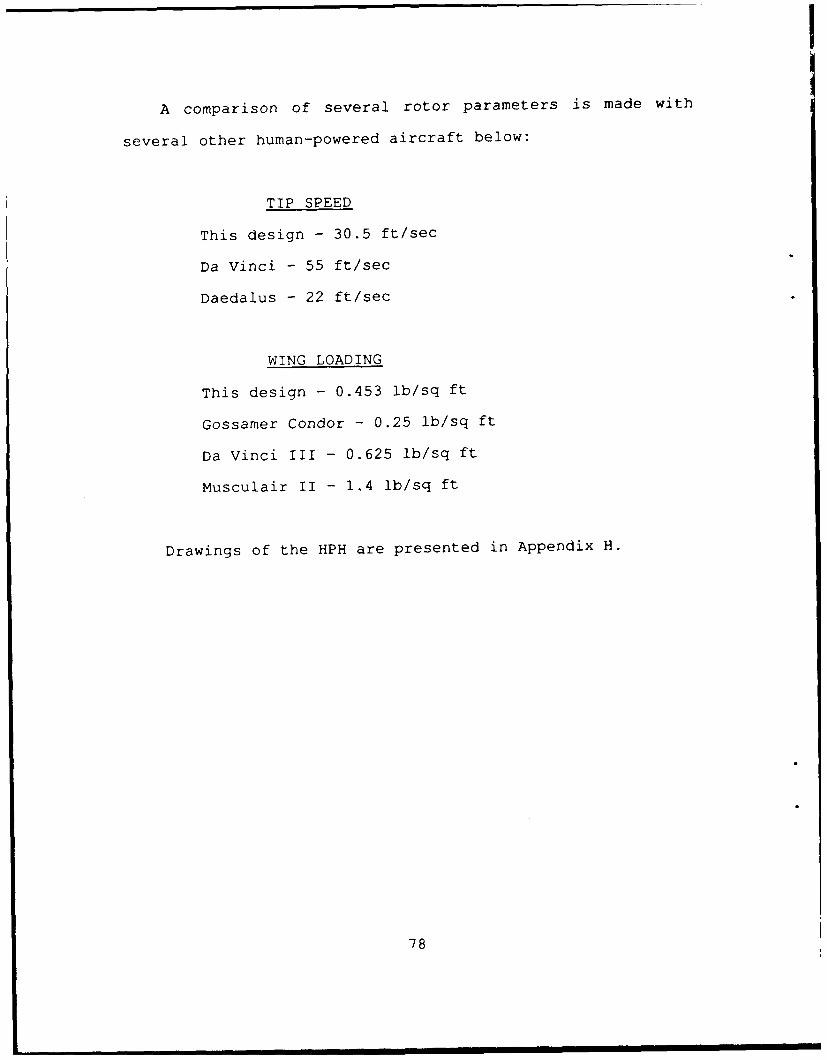
A comparison of several rotor parameters is made with
several other human-powered aircraft below:
TIP SPEED
This design - 30.5 ft/sec
Da Vinci - 55 ft/sec
Daedalus - 22 ft/sec
WING LOADING
This design - 0.453 lb/sq ft
Gossamer Condor - 0.25 lb/sq ft
Da Vinci III - 0.625 lb/sq ft
Musculair II - 1.4 lb/sq ft
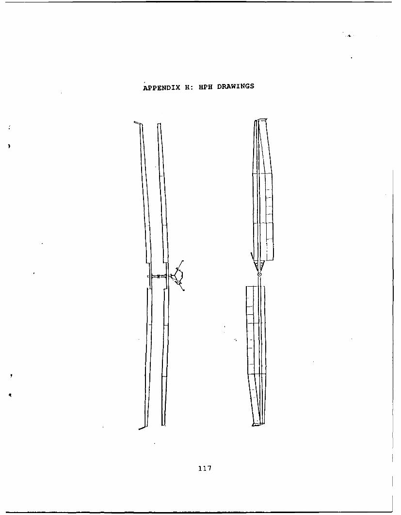
Drawings of the HPH are presented in Appendix H.
78
VI. CONCLUSIONS AND RECOMMENDATIONS
A. BENEFITS OF AN HPH PROGRAM
This paper concludes that a 72-ft diameter co-axial
helicopter can be hovered for one minute on human power. The
construction of a human-powered helicopter and completion of
a one minute hover to win the Igor I. Sikorsky Competition is
well within the capabilities of students at the NPS.
Construction of a human-powered helicopter at the NPS will
have many benefits to the school, aeronautical engineering,
naval aviation, and the Navy in general.
Winning the American Helicopter Society's competition will
represent a historically significant milestone. As the last of
Leonardo Da Vinci's ideas to be realized, winning the Igor I.
Sikorsky Human-Powered Helicopter Award will be an achievement
that will assure the school a great deal of prestige within
the aviation and engineering community. The publicity
generated from a successful flight will present a very
positive image for the NPS and the Navy in general.
In addition to the intangible rewards, there will be many
very real and positive benefits with respect to the
Aeronautical Engineering curriculum. One of the most needed
benefits of a program such as this will be the promotion of
the helicopter aerodynamics program at the NPS. The NPS has
79
probably the best body of helicopter knowledge of any
educational institution in the world. Approximately one-third
of the aeronautical engineering students are helicopter
pilots. These pilots include graduates of the U.S. Naval Test
Pilot School, undoubtedly the best helicopter test pilot
school in the world; pilots with several thousand helicopter
flight hours; pilots with significant fixed-wing hours as well
as rotary-wing hours; and pilots who were prior aircraft
maintainers. Also included as students are government service
and foreign engineers who are helicopter specialists. With
such an outstanding indigenous body of knowledge, the NPS
should be one of the leading helicopter research institutions
in the world.
The U.S. Army sponsors three universities within the U.S.
to conduct helicopter research. Called "Army Rotorcraft
Centers of Excellence," these universities include University
of Marylar , Rensselear Polytechnic Institute, and Georgia
Institute of Technology.[Ref.41: p.56] The Navy should
endeavor to make the NPS a similar facility for conducting
helicopter research for naval-related issues.
With all of the composite parts of the HPH, a program to
build an HPH will enhance the composite program and facilities
at the NPS. There is a very real need to educate naval
aeronautical engineers on advanced composite technology. Naval
aircraft of the future, such as the V-22 and the A-X, will
have signiticant portions of the airframe and associated
80
components fabricated from composite materials. The school
already has considerably less well equipped composite
facilities than other top-scale aeronautical engineering
universities in the U.S.
B. FLIGHT TEST OPPORTUNITIES
Given the nature of the body of helicopter knowledge at
the NPS, the particular strong point is flying knowledge and
experience. A simple aircraft such as an HPH would allow some
simple flight test opportunities without the tremendous
difficulties involved in flying military aircraft. The HPH can
be motorized and hover-power measured accurately for
performance testing. A flight test course is currently taught
within the department, and the aircraft would be an ideal
platform for use in that course. Some of the flight test
subjects possible for an HPH are presented in the following
subsections:
1. Highly flexible aircraft
Conventional aerodynamics assumes a rigid body; however,
airframes are non-rigid and airframe flexure affects aircraft
dynamic responses. Flight testing of highly flexible fixed-
testing of the Light Eagle that parameter estimation and
computational modeling became much more difficult and
complicated than was previously thought [Ref.42: p.349].
81
2. Instrumentation research
Developing ultra-light inflight instrumentation for the
HPH could lead to further developments for flight test or
operational use. The F-18 operational in-flight airframe-
stress-monitoring-system was an NPS by-product and is an
example of the type of instrumentation program that might
originate from instrumentation research on the HPH.
3. Flying Qualities
The HPH can be used as vehicle to teach and study flying
qualities. An understanding of the terms, influences and
variables concerning flying qualities is important for all
pilots.
4. Simulation
In this era of budget tightening, flight time will become
increasingly scarce. As a result, an increased emphasis will
be placed on simulation with respect to earning and
maintaining fleet qualifications. Just as it is important for
fleet aviators to know about real aircraft and aircraft
systems, so it is important to know about simulation and
simulators. Creation of a HPH simulator will be a means for
learning and applying those principles. An interdiscipline
subject, simulation incorporates everything from flight test
data to control systems to basic aerodynamics, and creates an
excellent learning and research opportunity.
82
C. AREAS TOR FUTURE RESEARCH
1. Low Reynolds number design and test
Even though a previously designed airfoil was used for the
HPH rotor blade, that is not to imply that a better one cannot
be developed. Low Reynolds number airfoil development is a
relatively unexplored field and is in need of research in a
variety of areas.
2. Flexible airfoil design and test
An extension of conventional airfoil design is flexible
airfoil design, where the surface coordinates vary as a
function of the pressure on the surface of the airfoil at that
point. To carry that concept one step further is to design a
deformable airfoil where the airfoil shape can be modified in
flight to achieve the desired flow characteristics. Research
in perfecting a HPH rotor blade airfoil can lead to
development in these fields.
3. Deep in ground effect hover theory
Ground effect theory begins to be difficult to extrapolate
below a Z/R of about 0.2. An accurate ground effect model for
low-induced-velocity rotors deep-in-ground-effect is not
available. This is an excellent opportunity to perform classic
aerodynamic research.
4. Tip losses for low induced velocity rotors/wings
Most rotor blade tip-loss models are semi-empirical and
meant to apply to conventional helicopters. Their application
83
to very-low-induced-velocity inflows appear somewhat dubious.
Investigation of conventional tip-loss theory to very-low-
induced-velocity inflows is an area for future research.
D. FOLLOW-ON WORK
The present HPH design represents the best configuration
for an HPH, given the present state of HPH theory. The design
incorporates the most efficient design features and includes
sufficient flexibility in construction and opera-ion. Follow-
on work in this field should be positive steps toward
construction of a prototype, as opposed to more design and
research. There is a great deal to be learned in the
construction process. Most importantly, a positive step toward
construction prevents the tendency to "over-design." In the
case of this HPH, some of the theory is questionable, and
further analysis will only needlessly complicate any further
design modifications. The best way to move on is to build,
flight test, refine and build again.
Construction can be broken down into finite steps and
phases capable of being accomplished by individuals performing
thesis work. Since many portions of the project can be
performed simultaneously, some of the next few steps toward
realization of a hoverable HPH are presented below in no
particular order.
84
1. Main rotor spar
Using the flight loads presented in this paper, a
composite main rotor spar needs to be designed, fabricated and
tested. Particular attention will need to be paid to the lay-
up to minimize the blade twist and any resulting coupling.
Test sections will need to be built and tested to ensure they
comform to the design criteria. A means for connecting each of
the sections and the blade grip needs to be designed, as well.
2. Main mast and reversing mechanism
The main mast, rotor blade hubs, and reversing mechanism
need to be built, fabricated and tested. A means for attaching
the rotor blades, feathering the blades (if flaps are not
used) and bearings and gears will need to be designed and
fabricated as well.
3. Ergometer
The structure of the ergometer is built, but the
instrumentation needs to be completed. Anthropometric data
and, power/gearing data resulting from testing on the
ergometer will be needed to design the undercarriage.
4. Main rotor blades
Construction of the rotor blades will require a tremendous
amount of manhours. Construction includes fabrication and
testing of ribs, and designing a means of fixing the ribs to
the spar. Construction of a test section will be needed to
determine rib spacing and qualify construction techniques.
85
Critical to the construction of the rotor blades will be
developing an efficient means of adhereing the Mylar to the
ribs to create a perfectly smooth, unwrinkled surface.
5. Undercarriage
Specific design and fabrication of t e composite
undercarriage, to include the seat, seatback crank hub and
support structure is needed. Information regarding dimensions
and optimum configuration from the ergometer will be necessary
before the design can be completed.
A. Flight control system
Development of a flight control system includes estimation
of airframe parameters, and sizing and shaping of the
winglets. The pilot controls and a sch-me to transfer ihe
inputs to the rotor blades need to be developed.
7. Construction of a simulator
A simulator will be used to select and train the pilot.
Construction of a simulator includes adapting the pilot
controls and interfacing the pedalling resistance with video
and controlling computer.
E. SUMMARY
The aerodynamic and structural theory required to design
a human-powered helicopter goes well beyond the limits
established for conventional helicopter design. As a result,
the basic tenets of helicopter design have been extrapolated
to the extreme limits in order to design a machine capable of
86
being hovered for one minute on one "humanpower." All of the
fields incorporated in helicopter design--aerodynamics,
structures, materials, controls, and propulsion--have been
combined to create the most simple and efficient helicopter
possible. The result of this design is a helicopter that is
capable of generating over 310 lbs of thrust per horsepower.
This HPH is a 72 ft diameter, co-axial design with two
blades on each rotor. The rotor blades have a constant chord
of 4.5 ft out to 0.67R where they are linearly tapered with a
taper ratio of 1.8. The DAI 1135 airfoil was selected for its
high power factor (C,3/2 /CD), low pitching moment, and tolerance
to surface imperfections. The airfoil was specially designed
to limit seperation bubble losses at a Reynolds number of
500,000 with the specific intent for use on human-powered
aircraft. Consequently, the rotor blades were designed--
keeping ease of construction in mind--to maintain the Reynolds
number as close as possible to 500,000 over the outboard half
of the rotor blade. The final design keeps the Reynolds number
within 86,000 of 500,000 over the outboard half of the rotor
blade. Various methods of energy management are explored
including using tip weights and using bending-to-torsion
coupling in the composite rotor blade spars.
Performance calculations were performed with a Fortran
program using blade element theory. A vortex lattice method
was also used to verify the blade element results, to provide
a more accurate representation of blade lift distribution for
q7
structural design purposes, and to provide circulation values
for the various blade stations. Various ground effect theories
were used, their results compared, and discrepency rationale
discussed. The effect of inflows on the lower set of blades
were calculated using a two-part induced-velocity model for
the upper blade, and the effects included in the performance
estimation. Although the power required to hover is a function
of the ground effect theory applied, the helicopter will
require approximately 1.25 hp to hover at 3 meters, and 0.8 hp
to hover just clear of the ground.
Human-power management is as critical as the aircraft
design itself and was studied exhaustively. A scheme for
calculating human power output versus time for different power
levels was devised using Miner's Rule for cumulative fatigue
damage to structural components. An ergometer was built to
test, select, and train the pilot, and to provide optimal
anthropometric and drive system data for undercarriage design.
Design and construction of past human-powered aircraft was
studied to glean ideas and learn from their mistakes. The
final result is a HPH capable of achieving an historical
milestone of international stature by winning the AHS
sponsored Igor I. Sikorsky Award for the first human-powered
helicopter.
In a speech given by Dr. Paul B. MacCready to a group of
researchers he outlined his distinguished record of
achievements in human-powered and solar-powered vehicles. He
88
stated that among the reasons for pursuing endeavors such as
these was "...changing attitudes and stimulating technology.
[Ref.43]" The helicopter is an aircraft of unparalleled
versatility with a somewhat maligned reputation. Recent events
such as the helicopter gunship successes in the Gulf War, have
helped to educate the general public regarding the
helicopter's true capabilities and versatility. In pursuing
the goal of building a human-powered helicopter, the project
helps create a positive awareness of the helicopter that has
historically been somewhat deficient.
Dr. MacCready also makes the point that attitudes have
been more important in shaping technological history than
technological innovation itself. He cites as an example,
Charles Lindbergh's Atlantic crossing as providing the public
awareness of aviation that generated the spirit and motivation
for many of the tremendous aviation developments of the
era. [Ref.43] This project--to develop, build and fly a human-
powered helicopter--is such a project.
89
REFERENCES
1. Drela, M. and Langford, J., "Human-powered Flight,"Scientific American, June 1988.
2. Burke, J. D., The Gossamer Condor and Albatross: A CaseStudy in Aircraft Design," AIAA Professional StudySeries, Report No. AV-R-80/540, 16 June 1980.
3. Patterson, W.B., "The Leonardo Da Vinci Flies! A VeryBrief Overview of the First Human Powered Hover,"Vertiflite, Mar/Apr 1990.
4. Dorsey, G., The Fullness of Winqs,lst ed., VikingPenguin, 1990.
6. Gay, R.R., "The Frame on the Frame," Bike Tech, April1988.
7. Okajima, S.,"RPM Versus Power," Cycling Science,September, 1990.
8. Drela, M., "Aerodynamics of Human Powered Flight,"AnnualReview of Fluid Mechanics, Annual Review Inc.,1990.
9. Grohsmeyer S, and others, A Design for a Human-PoweredHelicopter, AE 4306 Class Presentation, Naval PostgraduateSchool, Monterey, Ca., 1990.
10. Pfenninger, W. and Vemru, C.S., "Design of Low ReynoldsNumber Airfoils: Part I," Journal of Aircraft, vol.27,no.3, March 1990.
11. Marchman, J.F., "Aerodynamic Testing at Low ReynoldsNumbers," Journal of Aircraft, vol.24, no.2, February1987.
12. Drela, M., "Low Reynolds Number Airfoil Design for theM.I.T. Daedalus Prototype: A Case Study," Journal ofAircraft, vol.25, no.8, August 1988.
90
13. Mueller,T.J., "The Influence of Laminar Separation andTransition on Low Reynolds Number Airfoil Hysteresis,"Journal of Aircraft, vol.22, no.9, Sep 85.
14. Howard, R.M. and Kindelspire, D.W., "Freestream TurbulenceEffects on Airfoil Boundary Layer Behavior at Low ReynoldsNumbers," Journal of Aircraft, vol.27, no.25, May 90.
15. Howard, R.M. and Renoud, R.W., "Wing Boundary LayerResponse to an Unsteady Turbulent Flowfield," Journal ofAircraft, to be Published.
17. U.S. Department of Energy, A Catalog of Low ReynoldsNumber Airfoil Data For Wind Turbine Applications, Miley,S.J., Government Printing Office, Washington D.C., 1982.
18. Letter from P.B.S. Lissaman, Aerovironment Inc., toauthor, 24 Oct, 90.
19. Telephone conversation between Prof. Mark Drela, M.I.T.,and the author, 16 Apr 1991.
20. Facsimile from Prof. Mark Drela, M.I.T., to the author,16 Apr 1991.
21. Gessow, A. and Myers, G.C., Aerodynamics of theHelicopter, Fredrick Ungar, 8th printing, 1985.
22. Prouty, R.W., Helicopter Performance, Stability andControl, Robert E. Krieger, 1990.
23. U.S. Army Transportation Research Command, ParametricInvestigat-4on of the Aerodynamic and AeroelasticCharacteristics of Articulated and Rigid (Hingeless)Helicopter Rotors Systems, Trecom technical report 64-15,April 1964.
24. Johnson, W., Helicopter Theory, pp. 59-60, Princeton
Press, 1980.
25. Peters, D.A. and Chiu, Y.D.,"Extension of Classical Tiploss Formulas," AHS Journal,5, pp.68-71, April 1989.
26. Bertin, J.J., and Smith, M.L., Aerodynamics for Engineers,
28. Wood, E.R., and Hermes, M.E., Rotor Induced VelocitiesinForward Flight by Momentum Method, AIAA paper no. 69-224
29. Anderson, J.D., Fundamentals of Aerodynamics, 1st ed.,McGraw-Hill, 1984.
30. Prouty, R.W., Ground Effect In Hover," Rotor and Wing,February, 1991.
31. Daughaday, H. and Parrag, M.L., Helicopter Stability andContro Theory and Flight Test Techniques, PreliminaryDraft, CALSPAN report no.664z-F-10, 1983.
32. Telephone converstion between Mr. P. Zwann,AeroVironment Inc., and the author, October, 1990.
33. Judge, J.F., "Composite Materials: The comingRevolution, Airline Management and Marketing, September,1969.
34. National Aeronautics and Space Administration, NASAConference Publication 3104 Pt. 2, "Comparison of HandLaid-up tape and Filament Wound Composite Cylinders andPanels With and Without Impact Damage," First NASAAdvnccd Cop..sitc. Tcchnloy.. Cnfcrence, Jegley andLopez, 1991.
41. Zerweckh, S.H., and Von Flowtow, A.H., "Flight Testing AHighly Flexible Aircraft: Case Study on the MIT LightEagle, Journal of Aircraft, vol.27 no.4, Apr 90.
42. Lecture by Dr. Paul B. MacCready given as part of theChevron Research and Technology Distinguished SpeakersSeries, 16 May, 1991, Richmond, Ca.
93
APPENDIX A:FIGURES
- I-,
C4
d t
C'
c4 c
"-4 r
44 -
Figure A-I. ROTOR BLADE VORTEX DISTRIBUTION.
94
Lo PC
CLIP
Z,,, -,,..f -
%a al
ror
-J_\
rigur A-2, ROTOR. SD THUTLAING..
'95
| I,___ ___ _ *-
I,- N
((I) - -ll
# a
Ttt.re A 2,I ' R B/,/.D 'IIIU- I . £, D*N
95 *
/V
V-P.
4-0o
- gi i -
I,
o Olt It
(015'/11) ALI13012A O033nONI
Figure A-3. ROTOR SLADE INDUCED VELOCITY.
96
i0
.
0
CII '
Ot 0
* -o
O'0aOg Oi 0'0(uqg) ov~o
Figure A-4. ROTOR BLADE IN-PLANE DRAG.
97
6
U..
,
l JJ
C.,
%%%
01-1 IN 10M O.,3 1
LR PN I-I.N
98-
i1i
I-I
(ql-II -) lN31flOfl 0NI11Ld
Figure A-S, ROTOR DLADE PITChINtG MOMEN T.
98
APPENDIX B: TABLES
.3 STATI ON (:1 ORD I ,i 7I OLD 11DCED,.1!t) 1Pt)) .MBER VEI/W(, ITY
A prize of $20,000 is offered by the Americ3n HelicopterSociety for a successful controlled flight of a human poweredhel icopter.
This competition shall be conducted under the followingregulations and conditions laid down by the Human Powered
Helicopter Committee if the American Helicopter Society, and
shall be witnessed by the National Aero Club (NAC) who is thenational representative of the Federation Aeronautique
I irnationale (FAI). In the United States, the nationalrepresentative of the FAI is the National AeronauticAssociation (NAA) .
Note, The AHS has been advised by the Federal AviationAdministration (FAA) that, in the United States of America,registration and airworthiness certification will not berequired for machines built for this competition on theassumption that all flights will be limited to closeproximity to the ground and will generate no interferencewith air commerce. All intending entrants are stronglyadvised, during trials, to hold adequate insurance coveragefor all third party risks and to take every precautionagainst injury to people and damage to property. It isexpected that competitors in countries other than the U.S.A.will observe their own national flying and Insuranceregulations .
REGULATIONS
I. GENERAL
1.1 The prize will be awarded by the AHS to the entrantwho first fulfills the conditions.
1.2 Additionally, an attempt will be registered with theFederation Aeronautique Internationale (FAI) as aWorld Record for Hluman-Powered Helicopter Flightduration.
2. PRIZE
2.1 The AIIS prize is $20,600 in U.S. currency.
101
3. ELIGIBILITY
3.1 The competition is international and is open toIndividuals or teants from any part of the world.
3.2 For any and all questions regarding the acceptance ofentries, eligibility of an entrant, pilot, crew oraircraft under the regulations, or any other matterrelating to the IS prize, the decision of the AIS isfinal.
3.3 All questions regarding the world record attempt willbe governed by the sporting code of the FAI and restexclusively with the NAC.
4. CONDITIONS OF ENTRY
4.1 Aircraft
4.1.1 The machine shall be a heavier-than-air machine.The use of lighter-than-air gases shall be
prohibited.
4.1.2 The machine shall be a rotary wing configurationcapable of vertical takeoff and landing in stillair, and at least one member of the crew shall benon-rotating.
4.1.3 The machine shall be powered and controlled by thecrew during the entire flight, Includingaccelerating the rotor up to takeoff speed.
4.1.4 No devices for storing energy either for takeoff orfor use in, flight shall be permitted. Rotatingaerodynamic components, such as rotor blades, usedfor lift and/or control are exempt fromconsideration as energy storing devices.
4.1.5 No part of the machine shall be jettisoned duringthe flight including the rotor spin-up and takeoff.
4.2 Crew
4.2.1 The crew shall be those persons in the machineduring takeoff and flight, and there shall be nolimit set to their number.
4.2.2 No member of the crew shall be permitted to leaveor enter the aircraft at any time during takeoff or
flight.
102
4.2.3 No drugs or stimulants shall be used by any memberof the crew. An assurance must be g iven to theofficial observers at the time of the attempt thatthis requirement has been met.
4.2.4 Up to two handlers or ground crew shall bepermitted to assist in stabilizing the machineduring takeoff and landing, but in such a mannerthat they do not assist in accelerating ordecelerating any part of the machine.
4. 3 Ground Conditions
4.3.1 All attempts, which shall include the takeoff,shall be made over approximately level ground(i.e., with a slope not exceeding 1 in 100 in anydirection).
4.3.2 All attempts shall be made in still air, whichshall be defined as a wind not exceeding a meanspeed of approximately one meter per second (3.1kilometers per hour, 2.237 statute miles per hour,1.5 nautical miles per hour) over the period of theflight.
4. 4 Flight Requirements
4. 4.1 The flight requirements shall consist of hoveringfor one minute while maintaining flight within a10-meter square. During this time the lowest partof the machine shall exceed manentarily 3 metersabove the ground.
4.4.2 The machine shall be in continuous flight fromtakeoff to landing, and at. no time during theflight shall any part of the machine touch theg round.
4. 4.3 A reference point on the non-rotating part of themachine will be established as a means whereby theobservers can judge that the nachine stayed withinthe confines of the 19-meter square.
4.4.4 The one minute hovering time and the momentaryachievement of 3 meters altitude is required to winthe AI|S prize. (However, the FAI 1980 regulationsspecify that only the duration of the flight and amomentary achievement of 3 meters altitude will berecorded for the FAX world record attempt, makingit possible to achieve a world record withoutsatisfying the AIlS prize requiirements.)
103
4.5 Observation
Every attempt shall be observed by the UAC or by anypersons authorized by them to act as observers. It maytake place in the competitor' s own country if it isaffiliated with the FAI. In a country not so, it couldbe advantageous to conduct the flight in a neighboringcountry which is so affiliated.
5. APPLICATIONS FOR ENTRY
5.1 Entry forms shall be obtained from and returned tothe Anerican Helicopter Society, 217 NorthWashington Street, Alexandria, VA 22314, (703)684-6777.
5.2 The entry fee shall be U.S. $15 (made payable to theAmerican Helicopter Society).
5.3 Each entry form shall contain an application forofficial observation of the competitor's attempt.
5.4 The entrant shall undertake to abide by theconditions for official observation as set out onthe entry form and application for officialobservation and shall undertake to defray allexpenses incurred in connection with the officialobservation of the attempt.
5.5 The following fees and charges are made by the HAAfor record attempts In Class I, Human PoweredAircraft. ,All attempts shall be for national andinternational records.
5.6 Final notice of the proposed time and place of theattempt requiring official observation may, if sodesired, be sent to the AHS later than the entryform. It must in all cases be received at leastthirty days before the proposed date for theattempt. This time is required by the NAC (the NAAin the U.S.A.) to arrange for official observation.Applications will be considered in order of receipt.
5.7 Membership in the appropriate NAC and an FAI
Sporting License is required for all crew memberstaking part In this competition. Application formsmay be obtained from the NAC of the AIlS. For thiscompetition, a pilot's license is not required.
104
6; GEUERAL CONDITIONS
6.1 Insurance
The entrant must take out on behalf of himself, hiscrew, representatives or employees , liabilityinsurance in such form and mount to be specified bythe AilS, to indemnify the American lelicopterSociety, the MlAC and the FAI against any claims.Evidence that such insurance has been effected mustbe submitted with the application for officialobservation.
6.2 Revision of Regulations
6.2.1 These regulations shall remain in force until suchtime as the AIS considers it necessary to amendthem, or the prize has been won.
6.2.2 The AHS reserves the right to add to, amend or omitany of these regulations and to issue supplementaryregulations.
6.3 Interpretation of Regulations
The Interpretation of these regulations or any ofthe regulations hereafter Issued rest entirely withthe AIS. The entrant shall be solely responsible tothe official observer for due observance of theseregulations and shall be the person with whom theofficial observers will deal in respect thereof, orany other questions arising out of this competition.
The Sealed Super-Mini loed cell Isa precision sirairr riagn load call which Is waterproof and barornetl cc yirnsensitive It Is deitIgrred lot iesilrg, weighringi 9 forcre meirsuirementa In 100,100 8 compression Itrilolace*aapplication or prorrletery advericed malerinis irncirrorlogy. In strain gage anrd fiievrr design. produces loadcells with Ihe highrest accuracy In the IndisIry yfif priced comnpetitively wilth lower peplomirarwe t rItsThese ruggridcae have no movinrg pnrfs to we-if orrl or geli outo ar djusirnerlI lie specilicelione listred belowIllustrate iII re10 Pero e'lorrrrrurCe Of Intaerlece Sealed SSM Series load cells end are a major factor In thirworldwidle accepiance In appicateions suchir Astrirle force testing, thiust rreasuvernerrl. sieeryafd rodcornversion (to It- 44, and OIML rerquirements). conveyor scales, check weighrers. cournting end while acales,tensile loating end ersiqne dynear.r.n*ee*,For rnetric applications see Metric Sealed Super Moril Siles rrlirng SOON. 1000N. 2000N, and 500014 capacities
and mltic mounInrg lhreadaFor arptlications not requiring watlerproof saed units. see the Super-Mini series of load cells wh i olueResistanrt (MR) costing
SPEC1FJCAJ l0f4Sri
Non Llreelty-iii noled Oufllr .... ..... 0 05
Ilysleress-lit Fiaed Ouiput . .. 1003Non RepcalablIly-01 Saled Oulpul t. 0 .±02Temperature Range. Conipenseied- F . .. I- 15, 10 65,C) 01to 150Temperature Range, Opoirlig -'F , , .( - 55* to 901C) -651c, 200Temperature Effect on Soled oriput-% of fleadlrgnlO
06F (! of neading/5 60C) .. 0 06
Temperatrurc Effect on Zero-% led OulprrtiOO' (S's of noated Output/5 86C) ... 10 S
Creep, After 20 Min-I Soied OripuC' t 0 03Overload Reiings-%4 Pated Cnpaclty
Nonrinal Output-rnV/VN.... 3 /Zero Stieonce-si noted outpurt . . . ±Input ........-Ornr 3564-'50-35Outlput Reilcrce-Olrms .. 350 t 3 5Excitation Voltage
Pecomn-ended-VtPC to....1tnsulation Resistance. Bridge to Case -gorrrrs ..... 5000
111 Par SPIA * rtiad C.11 10-e. r.rrosr d Orr..e .,
(21 C... 0r ilfrt- ev is re,.sb'. ai .*d cePiara ('r-r ".r.r.ao *I ,aedi tsad. ft toe.Ia 0e,9 orerd load
107]
SEALED SUPER-VINIWALYOA LL&...
TENSION LOAD PRIMARY AXIS
INSTALLATION DIMENSIONS
MODEL A a C 0
SSM-s0 Inch 21 - ' - V .28 uW- mil 64 51 22 V.doep. lop & bottom
Inc to 2 _L _ . -2 LOIIF A Inch_ -A
Pi 64 SO Il V. deep. lop 9 boilom
SSM S00. 750. inch 3 2 . .20 WIFr2)1000. 2000. 3000 mm 7 5. 32 'A deep. lop & bollom
SSM 5 Inch 31 2 i. .- If ii-28
m 69 64 1 44 /. deep. lop & bollom C
ELECTRICAL INFORMATION
the SSM .50 lhru SSM-2So Is upplied wilh a 4 connector Shielded cable (AWO26) 10 (3m) long The SSM- 500 lhru SSM 5000 load ceol arl
I'pplled with a ;uggaed cable (PVC Jackl AW022) 10 it (3,) long or a Bendl PCO4E-06P connector A PCO6W lO-6S maling conneclof Isvalliable Il addlilonal cOIl.
Colnnector Cable lo.Ac1~ii
_ISSM.500 Ihiu 5000) (Al Modli)
pin Function Colo( Function 3; ZV xA +,Excitation Red # E.cllalioria + OulPul Olsen 4 Output
C -Output White - Oulpul [ FD -Ecitation Black - EcCilollonE No Collneclio Shield P40 ConecionoTNS
LF Ino Connect on IUPSCALE
Wliiiig Code Compile, with ISA 5378 Spec~llion and Tests for Shral Gage Force Transducers" and SMA toed Cal Termilnology
APPICAIO NO ES4. Jam nuts may be uasdt hoevoer, cats should be exercised 10 KmllAPPLCATON N TEShe Installatioii loiqtue a.r follo~s
I The $**led SupoiMiI food cell Is secillcolly designed loi outtdooi 631.1 So 20 inst pound. (2 21.iusage and thus can, be used In scale pits anid balclinrg pluil9 or 011.0, ON, 10C 5420 0ls one ( i.,tocallons th.1at. of cIcty eposed Ia th. weaether 650. 500 11-u SSI - 1000. 200 h,,i p-.ds8 1227 O.I.'
2 Atl easl one diameter thead engagement Ia desirable; normal SSM 2000 and SSUI 3000 SWo Inm p-udo (014..longegament Is shiown belowe: 8801 5000o I00 Inch poud. 41 13".h)
SSM -5O lhhfu 250: V." (amm)i t0 W I I 2mni) S Theloice 1 be masuf.d should be apiplied to the active end of theSSM. $00 Vihu 3000: W 112mm) so %- (16mnm) cowl to 0linilnal. possible eirois due 10 cable Iilcilom The aciveSSM-Sw 1%0 'A (i~mm I to 'A" 19,,) end of tie to Io Boearmlod Irom Otie cobte/connecior aide by the a"o
3 SSM- 5O thru and Includinig SSM. iWo or* anodized aluminum AN Iculoul) In lhe Ileaure (tie *oil*) numb.; to alveye shown on tieother unils ae *lecloless nickel plted s too l Inci,' side)Solloming out ofthe mounting alud cans cause Irreparable damage to the load cell.
I ERMS AND CONDITIONSOrd*"In informtion Sealed Suce FAinla ale ordeied by enecIlpIng 3 rom,, Hoa 30 days In U S dole,,. FOB Scoradole. Arizona U S A.Sella (SSM). Modl (AJ fh cable ofAF oS conneclor) and capecily 4. W n onen. Interface Inc Ma aard two year wanenl y to applicable(50 throughm 5000 ltis IEemPA SSM AJ 7?0 or SSl.4 AFl~ - 0bI he Sealed Super MnISeileslbed catl Intera, I.c cerifiles Vhal
2 PPckI. Consult you local Interface flopraaenlallsa 0r lie laclory o. cllillon mre sueameld s aoe@ teraeble t le be S. Niollnalfor price and delivery. Bureau o Slandarlds (NBS) a
Prices and . oeclticeflong puor c to Change wthout notice)
Unscerfa c e I ip . 41 f ng s ouienS O he OrleDAke. APARCOA aSEW USA. Ifh e'oee ff 0.ee
AOVAACEO bOfiC( MEASUvIE T 1121 N0-. USA
108
APPE NDIX 7: COMPUTER PROGRAMS
fiIIlr1o C PHIOIROGRAM W7~ 1 COMPUTE 111r, LIFT FOR A FOUR DLADED(-oo C i':'AzcoprER USING I'J.AVE ELEM4ENT THEORY
'le,';(7 Pl ~IROGRAM USES A LI14EAR TAPER FOR T111lE OUTBOARD 33%
I A 1 L, TST, TS4, Q, 0'T,TS, I V. I V', I VTA, CM, M'r111(11)'), I" Ntu', ' INPUT ROTO'.R RADIUS III FEETs
(IIIA IRRCiu 2""is 'mhIE 0FrF13ET
(J1.,10~ I IT 'INPUT 1I'111- ROOT C1101)fI AUD TI P CI1c'r1D III FEE'r,
11:1 Q1 ) rr", Lmr*, , 'INPUTr 'naE floTOR nRIMi in o j Cl 1TUAt' 1,OR
(1.1 U;., I()lI(22 C"I" IS TIlrl NUMBER OF 13LADE ELEMENTS
(I(I~l2r I Iwo0.
11026 Cl Cl, Cd. (4 Cm ARE FOR DAEI1 AIRFOIL
(0020 0,$ '001177
(I f) C 'ITSE VAI1UF;l';/ ARE FOR 0 AOA-F;,IR FLAT PITCHlI(0 " 5 I'.703
010032 C t'11 .01018(I'(1(13) rm itIs iim,0W ANGLE AND) IS EQUAl. TO T14E(100311 r IJ.ADE ANGLE. 8 DEGREES FOR r'ArE1.
110063 C,. "I'S" IS 1'IIE ELEMENTAL THIRUST(100166 TS-L*C0S~(rmI)-D*Suur(FIr)00I,067 TS4-TS/4
('0069 IF r OT (DI *RR) ) TI(EU't00(070 TS4-0"10071 TS-01)(1072 ENIF[1(10073 WRITE(10.,') R,TS40,0074'000)I75 C IeI'f1inWII):P VELOCITy110076 IV-SQRT(T04/(4A3, j4jlh .0123767AR*EDR))00077 C PRINT*,"R-' ,R, 'IND. VtZ. -' ,IV(101J70 WRITE(13,l)RC,RE,IV0)0079IM0030 C "TST"IS imr 'rUTAI, THRUS3T(10081010032 TST-TS'I4 TIJ(11.10813 C "10)" 1 I I 1-PLANE DR~AG
(10085 WRITE(11,*) RID
".0007 QT-QT i,01,080(W1009 loo CONTINUE
1,10090 200 CONTINUE '
0)0091 ''J.C'SE (10)10092 (,'I.,#,IE (11)('0093 (C'J,)3E (12)((1094 ''I/.'SE (13)00(095 V, I' - 111O(10096 r'i: I ?4T '(1fl097 I1JIN110 ITIE TOrAi, THRUST Tu rOIJHDS ISi ' TST(10098 iir'-OTOO/5500)0099 J17.JUT*D 'THE TO)TAL. IORSEPOWF;R REQUIRED ISs ' FlIP(10100 J'l11liTM 'THE TIP aPEED Iis,VT0)0103, FPIXtT11'THIE TIP LoSSES (BL AND) 92) ARE',DS,D2
111.WR~f~f OF' WAJiI1UG9 IN PROORAM UNIT: C,
JIIMB!R Or 2W'.D(RS IN PROGRAM UNIT: 0
(101103 OlfnRUUTINE REYHOLD (Cp,HE)
110
1:0104 k !' F-6,t 104ckV
IUMB ER OF Wt, l Ll IN PROGRAM IIlNIT111IMDCER OF ERJl l'P!3' IN PROGRAM UNITs 0
I IMDEU OF VIA1' I I IIJS IN COMPILAIONJ a 014N. L3M. OF .I IN COMP1LATION 0
'
111 *1
C.11 T[HIlS PRO(3RAPI')PITf 1*1l! LI FT OVER A PC'1'C'It T)ILDE'.10 0 U C ''ING THlE VOnlRTEX L.ATTICE MK;'I101. WITH (11-LY 011F CJ'IOR[DWIFE
Ill I(~!;I'Ar EL , THE. COORifDIrNATES '!"T TIHE PANELS AND CONT'IROL. POINTiSI~0(f.I ::I;I'. UP AS INI [).217-122 . roa MOD]r iY 11 PrPO'.-AM, THlE PANELJ
111107I' rl~lhIATE t4L~DTO E rT IN!TO A Fl LP CAL LED) VLM2 DAT. 'FIlEo'ioo.' C N\l PAY VAflT ABL1.W Ill N (0101 . 0002, 00101 ANDL (1(12 NEED) TO BE
11( 001) r'A!'.11ISTEL) J'o 'ifir m I' Irinr-:pj ';-q. PANELS, V 'IE PW'C)(1 PAM 1.11'31" IlE VALUE0111 I *'AM DENCLITY Fort STA1IIIAPII D'AY SEA LEVIL Ill VALEFO
0)l I 1-1111, P, RO0TOR f'I Amc'ER , ANI', ANILE OF A'VI'A(,% AP' IW'T) PROMPTED ANDI!U If '.El)- TO DIE ADJSTED IN 'l1r, DuL'Y OF THlE PRO(IrAM. THE SUBROUTINE ij
1)1101 31* C; (5 i MDUM i'I r' RO:M THY: [*POGRAM I VENI TN1 PE7. 23 p.(1101 'wc rROGflAm c'iri's TWO l I GAM74A . AT WHICH (IS A DATA FILE
roe, ir~ INI 4 ( RE IR'I(I!;L ADE ST'AION AK, ' (N CULAT I O , A14Do00 I. r' V! -1:3.DAT WHICH CONTAINS THlE ROTOR BLADE LrfA'I] oil AND LIFT AT THE
1,11036 VI.r12 OATCONTAINS, THlE I.A'1'l'1' COORr.'IN4ATES(1037 C7 X .X(I.Y (,I) ARE THlE coo~rmATES OF THlE CONTROL.-001030l (7 q . OINTS. 'ff:lo3( C X1II).Y1 (1) ARE TiHE LEFT HAND CORNERS OF THEA1) d0, (1l (", 1 11l5ESHOE VORrI CES .'i000401 r X2 (I ) Y2 (I ARE THlE PTGIlIT HlAND CORNERS OF TjiE
1)01.142 C IIORSESIIOE VORTICES%..('0043 101, 11 'ITi1NUE1100/1
0(10'3 '.'400 m-1,Z0(1O'1f5DO 300 iffi .7
001047
1.1). 0 i W2-1( (m)CN"x1I (1)' .2M XI ()) 41N yY 1 ~ (1Y()Y1()))
1) ) 05 20 0U153* W 3 - (X 2(N) 1 (IIt)I (X IM) 'X(N) Y 2 112 Y I (N) A (Y(M)-y I(N) ))
5 19 VA-VA-W(MV, I') kWW, N4 I)(0o1 60vo I t1 10753 o7ONTINUE0(1162 W(NV,N+1)-VA/W(IIV,NV)100163 loon (,(r1r I NUE00164
u o16 6 12.10()1 1.:itU' ,'MATRIX IS OINGULAP'
O If. 1673J1 t
APPENDIX G: MYLAR INFORMATION
MYP. PHYSICAL-THERMLAL
PROPERTIES
ON A ROLL WITH QUALITY
Mn #a polyester firm retains good physical Prop- thermal properties of Mriur are summarized Ineriles over a wide temperature range (-70*C to Table 1. Detailed Information and other physical+ 150'Q; and It is also used af temperatures from and thermal properties are described In the trmain-- 250*C to + 200'C when the physical require- Ing pages Of this bulletin.mnents are not as demanding. Some physical and
TABLE I
TYPICAL PHYSICAL AND THERMAL PROPERTIESOF MVYLARI POLYESTER FILM
PRPETYTYICL ALEMEASURE TEST METHOD
133,
Strengh at 5Elonatin M 152 1500 SI ATM 88
(FS To 4700 1380 PSIASTM0 I8
1VTU2 S4VTU2-' .tSP7(W-WIf W4
116S II Wif. LT
APPENDIX H: HPH DRAWINGS
117
"Jill
119
INITIAL DISTRIBUTION LIST
1. Defense Technical Information Center 2Cameron StationAlexandria, Va 22304-6145
2. Library, Code 0142 2Naval Postgraduate SchoolMonterey, Ca 93943-5000
3. Chairman, Dept. Aeronautics and Astronautics 1Naval Postgraduate SchoolMonterey, Ca 93943-5000
4. Prof R.M. Howard 1Code 31Naval Postgraduate SchoolMonterey, Ca 93943-5000
5. Prof E.R. Wood 1Code 31Naval Postgraduate SchoolMonterey, Ca 93943-5000
6. Mr. D.E. Blish 1PEMCO AEROPLEXP.O.Box 929Dothan, Al 36302
7. Mr. P. Zwann 1225 Churchill Rd.Sierra Madre, Ca 91024
8. Lcdr. S.A. Bruce 1P.O. Box 179Valley Lee, Md 20692