Page 1
Portland State University Maseeh College of Engineering and Computer Science
ME 493 Final Report – Year 2012
HUMIDIFYING A SEALANT CURE OVEN
June 11th, 2012
Team Members:
THONG TRUONG
PAUL LUCAS
KHOI NGUYEN
ASGEDOM GEBREHIWOT
MIRCEA BEC
MESHARI Al EBRAHIM
Academic Advisor:
DR. FARYAR ETESAMI
Industrial Advisor:
RORY OLSON
Page 2
2
Executive Summary
Boeing is the world’s leading aerospace company and the largest manufacturer of commercial
and military aircrafts. With an ever-increasing product line, more efficient manufacturing and
design process is required in order to meet customer needs. As a result, the proper application of
sealant to the aircraft parts is essential in achieving the required quality and reliability. The
application of sealant on the aircraft parts prevents them from getting corroded which
jeopardizes the load carrying capability of the aircrafts. The sealant curing process requires
controlled temperature and relative humidity conditions in order to avoid extensive and costly
maintenance. Boeing’s current sealant curing method is inconvenient and inefficient. Boeing
would like to improve upon the current curing methods.
Rory Olson, a research and development engineer at Boeing approached the MCECS in order to
improve the current curing method. The Boeing’s senior design team is designing a humidity
controlled curing oven which will be retrofitted to Boeing’s current ovens. A prototype will be
delivered by June 2012.
The oven has been modified with a new insulation and installed a humidifier to control the
humidity as well as the temperature by Portland State University’s Capstone Team 2012 and
ready to be displayed to Boeing. The team has followed strictly to the steps of the design process
to satisfy all the requirements from problem design specification to prototyping and testing. This
document will familiarize the reader with the final design concept and design of the oven as well
as testing results and various evaluations showing the oven meets all the design specifications.
Page 3
3
Contents
Executive Summary ...................................................................................................................................... 2
Introduction and Background ....................................................................................................................... 4
Mission Statement ......................................................................................................................................... 5
Main Design Requirements ........................................................................................................................... 6
Top Level Design Alternatives ..................................................................................................................... 6
Final Design .................................................................................................................................................. 8
Mechanical System ....................................................................................................................................... 9
Structure .................................................................................................................................................... 9
Electrical System..................................................................................................................................... 10
Water Supply .......................................................................................................................................... 10
Evaluation of Quality and Reliability ......................................................................................................... 10
Evaluation of Safety and Ergonomics ......................................................................................................... 10
Evaluation of Cost and Financial Performance ........................................................................................... 11
Evaluation for Mobility and Capacity ......................................................................................................... 11
Dimension ............................................................................................................................................... 11
Weight ..................................................................................................................................................... 11
Capacity .................................................................................................................................................. 12
Structural ................................................................................................................................................. 12
Maintenance ............................................................................................................................................ 12
Conclusion .................................................................................................................................................. 13
Appendixes ................................................................................................................................................. 14
Appendix A: Product Development Specifications ................................................................................ 14
Appendix B: Decision Matrix ................................................................................................................. 18
Appendix C: Project Timeline ................................................................................................................ 19
Appendix D: Calculations for Pressure, Heat Loss, and Mass Flow Rate ............................................. 20
Appendix E: Drawings & Models ........................................................................................................... 22
Appendix F: Part Illustrations and Humidifier Circuit Diagram ............................................................. 23
Appendix G: References ........................................................................................................................ 25
Page 4
4
Introduction and Background
Boeing designs aircrafts that resist corrosion through the use of proprietary corrosion inhibiting
sealants. The sealant curing process is essential in order to guarantee the quality and reliability of
the aircraft and control corrosion to avoid jeopardizing the intended load carrying capability of
the airplane [3]. The sealant curing process requires controlled temperature and relative humidity
conditions in order to avoid extensive and costly maintenance.
Boeing uses a two-component polysulfide sealant containing corrosion inhibiting chromate to
effectively eliminate corrosion. Two current approaches of curing the sealant are the “traditional”
and “lean” methods.
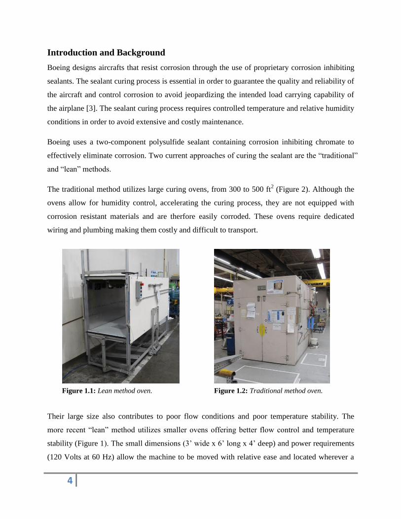
The traditional method utilizes large curing ovens, from 300 to 500 ft2 (Figure 2). Although the
ovens allow for humidity control, accelerating the curing process, they are not equipped with
corrosion resistant materials and are therfore easily corroded. These ovens require dedicated
wiring and plumbing making them costly and difficult to transport.
Their large size also contributes to poor flow conditions and poor temperature stability. The
more recent “lean” method utilizes smaller ovens offering better flow control and temperature
stability (Figure 1). The small dimensions (3’ wide x 6’ long x 4’ deep) and power requirements
(120 Volts at 60 Hz) allow the machine to be moved with relative ease and located wherever a
Figure 1.1: Lean method oven. Figure 1.2: Traditional method oven.
Page 5
5
typical wall outlet can be found. However, these ovens are not equipped with humidity control
and also require fixed plumbing.
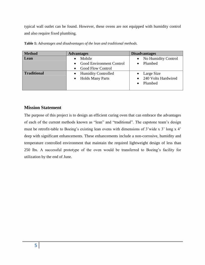
Table 1: Advantages and disadvantages of the lean and traditional methods.
Method Advantages Disadvantages
Lean Mobile
Good Environment Control
Good Flow Control
No Humidity Control
Plumbed
Traditional Humidity Controlled
Holds Many Parts
Large Size
240 Volts Hardwired
Plumbed
Mission Statement
The purpose of this project is to design an efficient curing oven that can embrace the advantages
of each of the current methods known as “lean” and “traditional”. The capstone team’s design
must be retrofit-table to Boeing’s existing lean ovens with dimensions of 3’wide x 3’ long x 4’
deep with significant enhancements. These enhancements include a non-corrosive, humidity and
temperature controlled environment that maintain the required lightweight design of less than
250 lbs. A successful prototype of the oven would be transferred to Boeing’s facility for
utilization by the end of June.
Page 6
6
Main Design Requirements
A detailed list of customer’s requirements was specified in the PDS document which is attached
in Appendix A. The main design requirements are summarized below.
Humidity inside the oven must be controlled at 50±5% RH.
Temperature inside the oven needs to be maintained at 130±5oF.
The designed oven is expected to last for at least 5 years.
No silicone products may be used in the fabrication or assembly of the oven.
The size of the oven for this project will be 3’wide x 3’tall x 4’deep chamber that opens
on both ends.
There should be minimum maintenance required once the oven is deployed.
Power source for operating the oven must be 120v AC at 60Hz.
The designed oven should not be plumbed; it must have an onboard water supply with a
35lb weight limit.
Top Level Design Alternatives
In the internal and external search section of the design process, three of the most common
methods in controlling the humidity were researched: water atomizing, steam injection, and
water bath evaporation. The top level design of this project is focused on controlling the
humidity at ±50% RH and the temperature at 135 o ± 5
oF. There are several factors that impact
the final design: the positioning of the water supply, humidifying mechanism, performance, cost,
and manufacturability. After extensive discussions and evaluations, there were three alternative
designs which needed to be considered. The strengths and weakness of each alternative are
summarized below.
Page 7
7
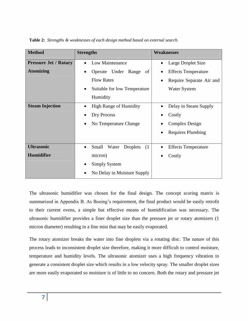
Table 2: Strengths & weaknesses of each design method based on external search.
Method Strengths Weaknesses
Pressure Jet / Rotary
Atomizing
Low Maintenance
Operate Under Range of
Flow Rates
Suitable for low Temperature
Humidity
Large Droplet Size
Effects Temperature
Require Separate Air and
Water System
Steam Injection High Range of Humidity
Dry Process
No Temperature Change
Delay in Steam Supply
Costly
Complex Design
Requires Plumbing
Ultrasonic
Humidifier
Small Water Droplets (1
micron)
Simply System
No Delay in Moisture Supply
Effects Temperature
Costly
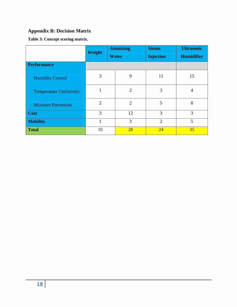
The ultrasonic humidifier was chosen for the final design. The concept scoring matrix is
summarized in Appendix B. As Boeing’s requirement, the final product would be easily retrofit
to their current ovens, a simple but effective means of humidification was necessary. The
ultrasonic humidifier provides a finer droplet size than the pressure jet or rotary atomizers (1
micron diameter) resulting in a fine mist that may be easily evaporated.
The rotary atomizer breaks the water into fine droplets via a rotating disc. The nature of this
process leads to inconsistent droplet size therefore, making it more difficult to control moisture,
temperature and humidity levels. The ultrasonic atomizer uses a high frequency vibration to
generate a consistent droplet size which results in a low velocity spray. The smaller droplet sizes
are more easily evaporated so moisture is of little to no concern. Both the rotary and pressure jet
Page 8
8
atomizing methods require air pressure. The ultrasonic system is pressure-free making it simpler
to design.
Steam injection requires a boiler to be kept at a high temperature in order to provide steam to the
chamber. This process utilizes both a large quantity of water and energy. The amount of water
needed to supply the boiler is sufficient enough to require the system be plumbed. In comparison,
the ultrasonic humidifier runs at room temperature requiring very little power (45 Volts) and
allows for a gravity fed water supply to be used, meeting the product design specifications.
Final Design
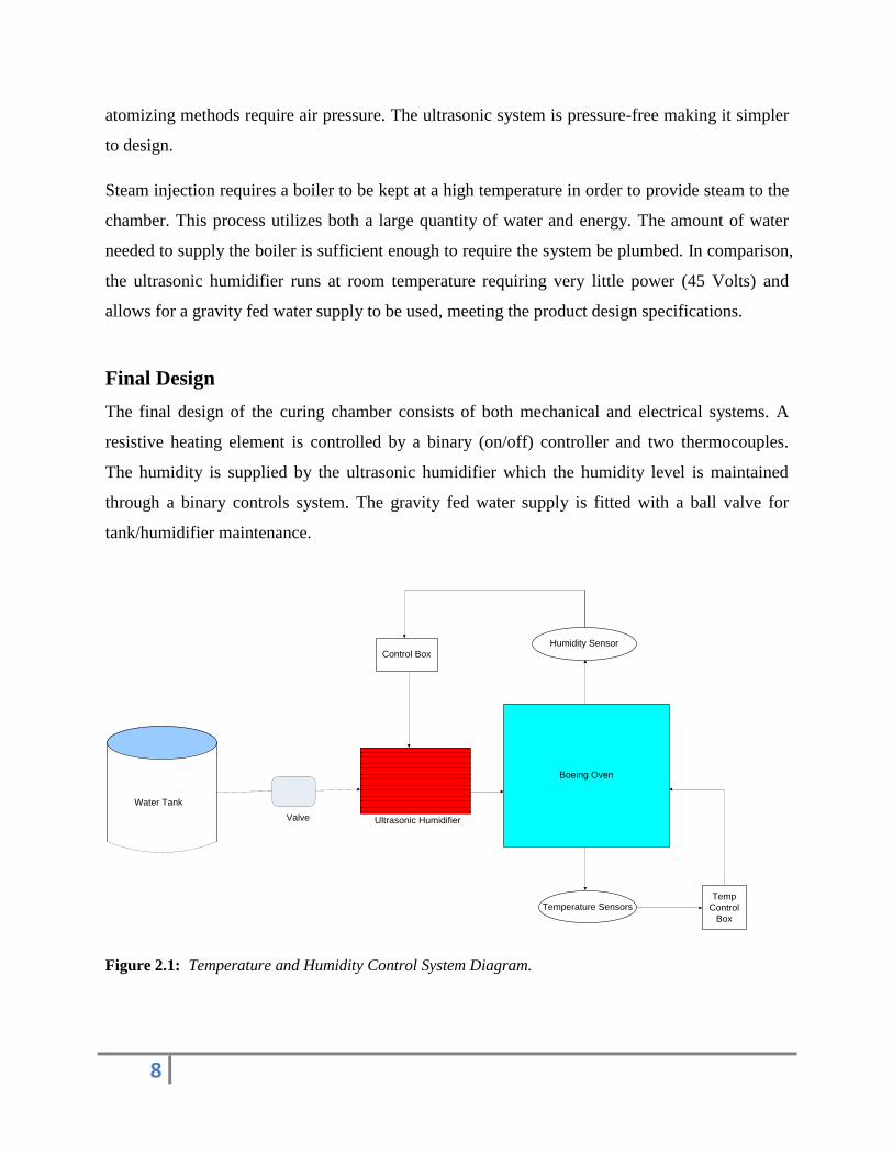
The final design of the curing chamber consists of both mechanical and electrical systems. A
resistive heating element is controlled by a binary (on/off) controller and two thermocouples.
The humidity is supplied by the ultrasonic humidifier which the humidity level is maintained
through a binary controls system. The gravity fed water supply is fitted with a ball valve for
tank/humidifier maintenance.
Ultrasonic Humidifier
Water Tank
Boeing Oven
Temperature Sensors
Humidity Sensor
Temp
Control
Box
Control Box
Valve
Figure 2.1: Temperature and Humidity Control System Diagram.
Page 9
9
Operation of the sealant oven may be characterized into three modes:
I. Heating mode: The heating element is turned on and the temperature is brought
up 135 oF. During this time the part may be inserted into the oven to reach oven
temperature, preventing condensate from accumulating on the part.
II. Curing mode: Once the oven has reached operating temperature the humidifier
will be activated bringing the humidity to 50% RH. The RH and temperature
controllers will maintain the operating conditions throughout the curing process.
III. Cooling mode: The system will be switched off and the oven doors opened to
allow for a rapid cool down process.
Mechanical System
The mechanical components of the curing chamber determine the performance, maintenance,
and structural integrity of the system. The system consists of four major components: the shell
and structure, water supply and electrical systems.
Structure
As received by Boeing, the ovens structural members where constructed from extruded
aluminum T-slot channel. For this reason the structural members used in the design of all new
system components used the same.
In detail, a 1/16th
inch 6061-T6 aluminum sheeting was used for the oven shell for several
reasons. Firstly, its light weight helps meet the weight requirements stipulated by the PDS.
Secondly, it is relatively easily formed and cut which allowed the team to utilize the tools
provided by the Mechanical Engineering Departments machine shop. Thirdly, it is relatively
corrosion resistant at the ovens operating conditions and cheap to replace. All the necessary
shapes were designed in SolidWorks and then drawn onto the metal sheeting for cutting and
bending.
As mentioned all structural parts utilized extruded aluminum T-slot channel. SolidWorks was
used to design the components to mount the humidifier, controls box, and water supply (Refer to
Appendix E for drawings). To facilitate maintenance and assembly the gussets, brackets, corner
plates, and screws where all compatible with the T-slot channel.
Page 10
10
To retard heat transfer, the inner walls of the oven are lined with 1½ inch blanket fiberglass
insulation with an R-value of 30 and a layer of foil single bubble insulation to minimize heat
transfer due to radiation.
Electrical System
The 48 VDC operating voltage for the Ultrasonic humidifier is switched on and off by a solid
state DC relay controlled by the Level Controller (Stultz Air Technology Systems, Inc., 2012).
The level controller, microprocessor based, receives input from the sensors (RH and Temp.) and
in turn controls the float valves (filling the humidifier unit), fan, and nebulizers. When signal is
sent to the processor it checks the low and high water float switches. If the water is too low, the
water fill valve solenoid is switched on and monitored until the water level reaches the high level,
it is then turned off. When the water level is above the low water level the fan is turned on to
push the mist from the nebulizer unit.
Water Supply
The water supply is made of clear plastic allowing the end user to visually determine the water
level. A valve is fitted between the supply and the humidifier for maintenance purposes.
Evaluation of Quality and Reliability
Based on the specification of the ultrasonic humidifier and its components, the prototype is
theoretically reliable as the humidifier can be operated up to 24 hours per day, which is more
than sufficient as the typical testing takes only 6 hours. The components of the humidifier are
easily replaceable upon failure. Some of the components that are susceptible to possible failure
are the fuse, nebulizer unit, print plate, float switch, solenoid valve and circuit board, these
components are easily replaceable.
Evaluation of Safety and Ergonomics
The humidifier unit is equipped with internal safety mechanisms. The safety control is built into
the microprocessor. The voltage supplied to the nebulizer affects the amount of mist produced.
Voltage exceeding the 48V operating conditions will damage the transducer while too low a
voltage restricts mist production. The processor monitors the voltage within a range, if out of
Page 11
11
this range the processor will not send current to the solid state relay (Stultz Air Technology
Systems, Inc., 2012). In the same manner if the temperature dips out of operating range or the
water stops being supplied via the float valves the microprocessor turns off the solid state relay
and fan and drains the tank to avoid freezing. An LED mounted on the control box will signal
alarm should any of the above happen.
Ergonomics required that the end user lift no more than 35 pounds over 5 feet high. This
constraint was met by providing a pump to bring water into the systems water supply. This
allows the end user to use a hand cart to bring a 5 gallon jug of water over to the oven, place the
pump in the 5 gallon tank and fill the onboard water supply without lifting any weight.
Evaluation of Cost and Financial Performance
The total budget for this particular project was set to be around $5,000. The amount of money
spent on purchasing parts reached roughly $4,100. With labor cost not taken in consideration, the
amount of money spent was considered as development cost. All parts were purchased and
approved by Boeing Company. By keeping the development cost under budget all desirable goal
were met.
Evaluation for Mobility and Capacity
Dimension
After rebuilding the interior of the oven to fit for humidity, dimensions remained the same (3ft x
3ft x 4ft). The ultrasonic-humidifier in comparison to the other methods is relatively small
(10.71” x 8.27), which meets the requirements of having system that will retrofit with Boeing’s
current ovens.
Weight
The whole system (water tank, ultrasonic humidifier, interior design) weights approximately
80lb which meets the requirement of 100lb.
Page 12
12
Capacity
The mass flow-rate of the current design (Stulz-Ultrasonic Humidifier) ranges from 0 to 4.4
lbm/hr, which meets the 1.46 lbm/hr requirement.
Structural
The interior was rebuilt using 6061-Aluminum plate (1/16” thick). Aluminum T-slot beam were
used to mound the humidifier and water thank in place. Other components such as: PVC and
flexible tubes, sensors, valves, vinyl tubes and electric wires were also used at the assembly of
the system.
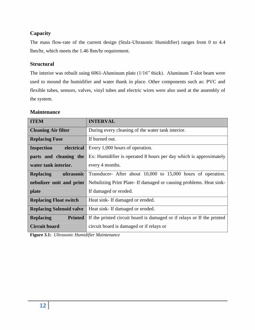
Maintenance
ITEM INTERVAL
Cleaning Air filter During every cleaning of the water tank interior.
Replacing Fuse If burned out.
Inspection electrical
parts and cleaning the
water tank interior.
Every 1,000 hours of operation.
Ex: Humidifier is operated 8 hours per day which is approximately
every 4 months.
Replacing ultrasonic
nebulizer unit and print
plate
Transducer- After about 10,000 to 15,000 hours of operation.
Nebulizing Print Plate- If damaged or causing problems. Heat sink-
If damaged or eroded.
Replacing Float switch Heat sink- If damaged or eroded.
Replacing Solenoid valve Heat sink- If damaged or eroded.
Replacing Printed
Circuit board
If the printed circuit board is damaged or if relays or If the printed
circuit board is damaged or if relays or
Figure 3.1: Ultrasonic Humidifier Maintenance
Page 13
13
Conclusion
This document reflects all designs, requirements and product design specifications we have
determined that our third chosen design has met all specified requirements effectively and
working within the constraints given by Boeing. The final design was the most simple and
efficient in term of structure, quality, reliability and maintenance. It was quite expensive, but it
fitted our dedicated budget. Since the design is a proof of concepts device, we have shown that
within the requirements listed the concept of sealant cure oven is achievable within budget,
performance and maintenance requirements. The only issue that we have to face is the missing
control panel due to the delay from the vendor, so we are not yet to be able to fully test our
prototype. We have done some initial tests based on the Home Depot humidifier and it met the
PDS requirements. We are confident that as soon as we receive the control panel, our final
prototype will satisfy all the requirements. Overall, our design has met the performance, quality,
reliability, and life in service requirements. We will keep working on installing the control panel
to the oven once we receive it. Several tests will be made to verify the validation of the data
based on the product design specifications and requirements from Boeing.
Page 14
14
Appendixes
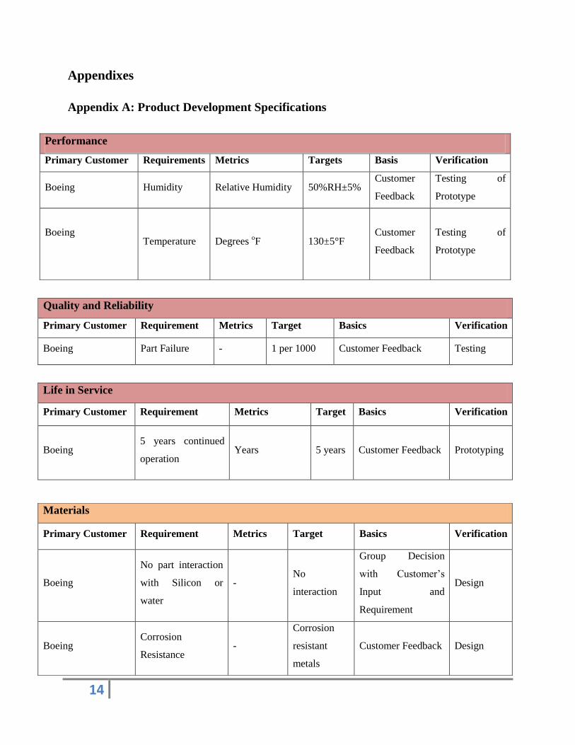
Appendix A: Product Development Specifications
Quality and Reliability
Primary Customer Requirement Metrics Target Basics Verification
Boeing Part Failure - 1 per 1000 Customer Feedback Testing
Life in Service
Primary Customer Requirement Metrics Target Basics Verification
Boeing
5 years continued
operation Years
5 years
Customer Feedback Prototyping
Performance
Primary Customer Requirements Metrics Targets Basis Verification
Boeing Humidity Relative Humidity 50%RH±5% Customer
Feedback
Testing of
Prototype
Boeing
Temperature Degrees oF 130±5°F
Customer
Feedback
Testing of
Prototype
Materials
Primary Customer Requirement Metrics Target Basics Verification
Boeing
No part interaction
with Silicon or
water
- No
interaction
Group Decision
with Customer’s
Input and
Requirement
Design
Boeing Corrosion
Resistance -
Corrosion
resistant
metals
Customer Feedback Design
Page 15
15
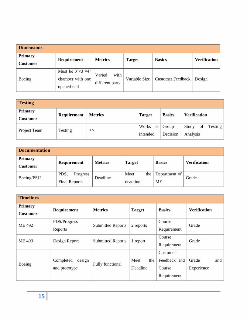
Dimensions
Primary
Customer Requirement Metrics Target Basics Verification
Boeing
Must be 3’×3’×4’
chamber with one
opened-end
Varied with
different parts Variable Size Customer Feedback Design
Testing
Primary
Customer Requirement Metrics Target Basics Verification
Project Team Testing +/- Works as
intended
Group
Decision
Study of Testing
Analysis
Documentation
Primary
Customer Requirement Metrics Target Basics Verification
Boeing/PSU PDS, Progress,
Final Reports Deadline
Meet the
deadline
Department of
ME Grade
Timelines
Primary
Customer Requirement Metrics Target Basics Verification
ME 492 PDS/Progress
Reports Submitted Reports 2 reports
Course
Requirement Grade
ME 493 Design Report Submitted Reports 1 report Course
Requirement Grade
Boeing Completed design
and prototype Fully functional
Meet the
Deadline
Customer
Feedback and
Course
Requirement
Grade and
Experience
Page 16
16
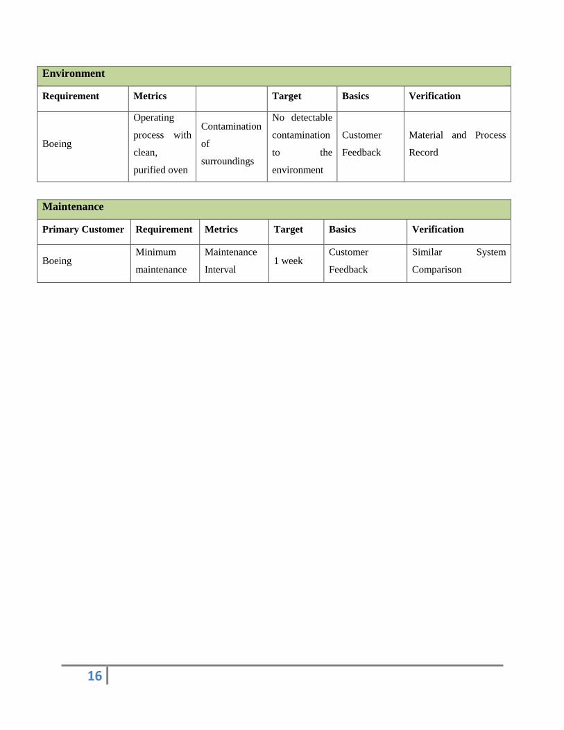
Environment
Requirement Metrics Target Basics Verification
Boeing
Operating
process with
clean,
purified oven
Contamination
of
surroundings
No detectable
contamination
to the
environment
Customer
Feedback
Material and Process
Record
Maintenance
Primary Customer Requirement Metrics Target Basics Verification
Boeing Minimum
maintenance
Maintenance
Interval 1 week
Customer
Feedback
Similar System
Comparison
Page 17
17
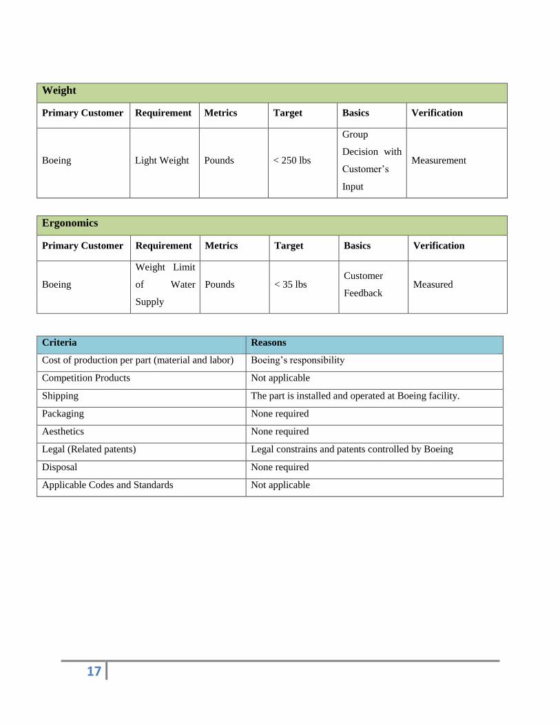
Weight
Primary Customer Requirement Metrics Target Basics Verification
Boeing Light Weight Pounds < 250 lbs
Group
Decision with
Customer’s
Input
Measurement
Ergonomics
Primary Customer Requirement Metrics Target Basics Verification
Boeing
Weight Limit
of Water
Supply
Pounds < 35 lbs Customer
Feedback Measured
Criteria Reasons
Cost of production per part (material and labor) Boeing’s responsibility
Competition Products Not applicable
Shipping The part is installed and operated at Boeing facility.
Packaging None required
Aesthetics None required
Legal (Related patents) Legal constrains and patents controlled by Boeing
Disposal None required
Applicable Codes and Standards Not applicable
Page 18
18
Appendix B: Decision Matrix
Table 3: Concept scoring matrix.
Weight
Atomizing
Water
Steam
Injection
Ultrasonic
Humidifier
Performance
Humidity Control
Temperature Uniformity
Moisture Prevention
3 9 11 15
1 2 3 4
2 2 5 8
Cost 3 12 3 3
Mobility 1 3 2 5
Total 10 28 24 35
Page 19
19
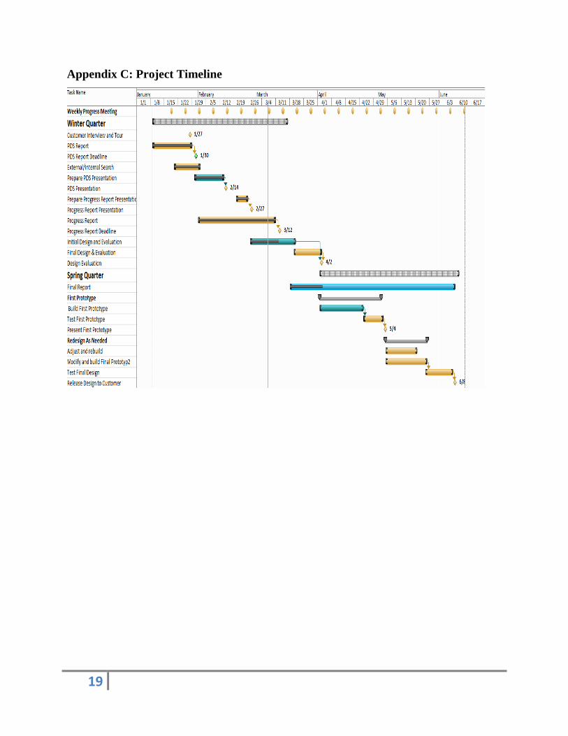
Appendix C: Project Timeline
Page 20
20
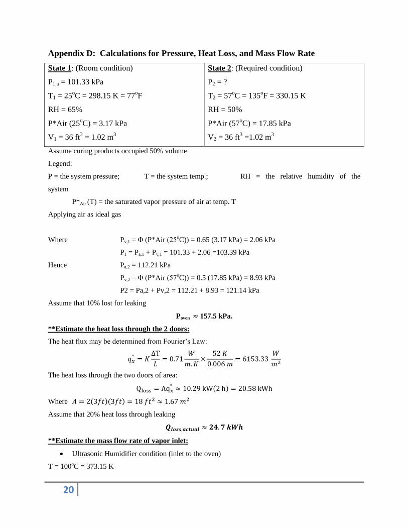
Appendix D: Calculations for Pressure, Heat Loss, and Mass Flow Rate
State 1: (Room condition)
P1,a = 101.33 kPa
T1 = 25oC = 298.15 K = 77
oF
RH = 65%
P*Air (25oC) = 3.17 kPa
V1 = 36 ft3 = 1.02 m
3
State 2: (Required condition)
P2 = ?
T2 = 57oC = 135
oF = 330.15 K
RH = 50%
P*Air (57oC) = 17.85 kPa
V2 = 36 ft3 =1.02 m
3
Assume curing products occupied 50% volume
Legend:
P = the system pressure; T = the system temp.; RH = the relative humidity of the
system
P*Air (T) = the saturated vapor pressure of air at temp. T
Applying air as ideal gas
Where Pv,1 = Φ (P*Air (25oC)) = 0.65 (3.17 kPa) = 2.06 kPa
P1 = Pa,1 + Pv,1 = 101.33 + 2.06 =103.39 kPa
Hence Pa,2 = 112.21 kPa
Pv,2 = Φ (P*Air (57oC)) = 0.5 (17.85 kPa) = 8.93 kPa
P2 = Pa,2 + Pv,2 = 112.21 + 8.93 = 121.14 kPa
Assume that 10% lost for leaking
Poven 157.5 kPa.
**Estimate the heat loss through the 2 doors:
The heat flux may be determined from Fourier’s Law:
The heat loss through the two doors of area:
( )
Where ( )( )
Assume that 20% heat loss through leaking
**Estimate the mass flow rate of vapor inlet:
Ultrasonic Humidifier condition (inlet to the oven)
T = 100oC = 373.15 K
Page 21
21
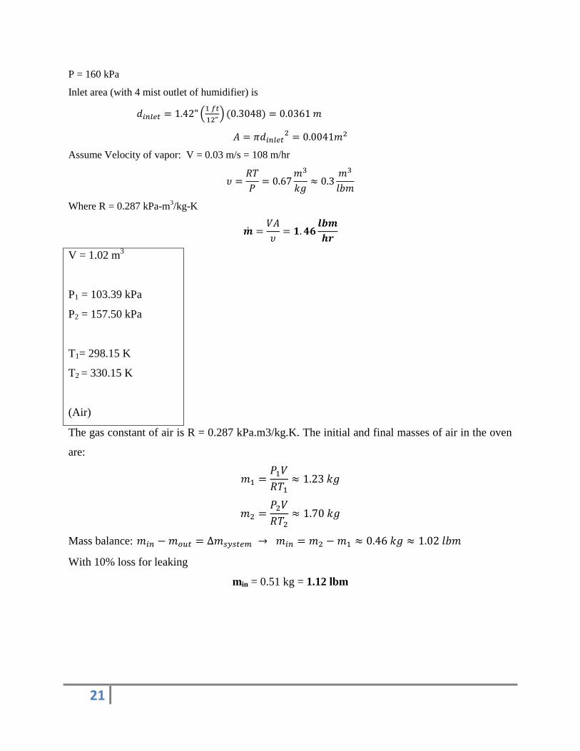
P = 160 kPa
Inlet area (with 4 mist outlet of humidifier) is
(
) ( )
Assume Velocity of vapor: V = 0.03 m/s = 108 m/hr
Where R = 0.287 kPa-m3/kg-K
V = 1.02 m3
P1 = 103.39 kPa
P2 = 157.50 kPa
T1= 298.15 K
T2 = 330.15 K
(Air)
The gas constant of air is R = 0.287 kPa.m3/kg.K. The initial and final masses of air in the oven
are:
Mass balance:
With 10% loss for leaking
min = 0.51 kg = 1.12 lbm
Page 22
22
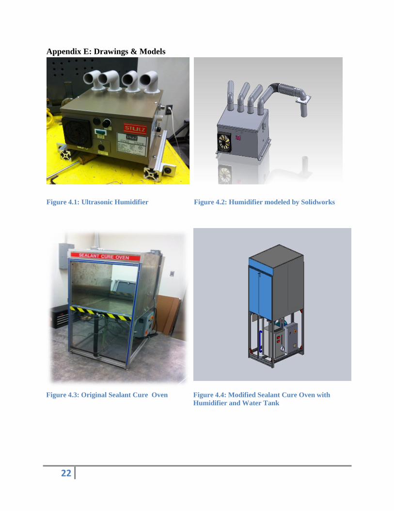
Appendix E: Drawings & Models
Figure 4.1: Ultrasonic Humidifier
Figure 4.2: Humidifier modeled by Solidworks
Figure 4.3: Original Sealant Cure Oven Figure 4.4: Modified Sealant Cure Oven with
Humidifier and Water Tank
Page 23
23
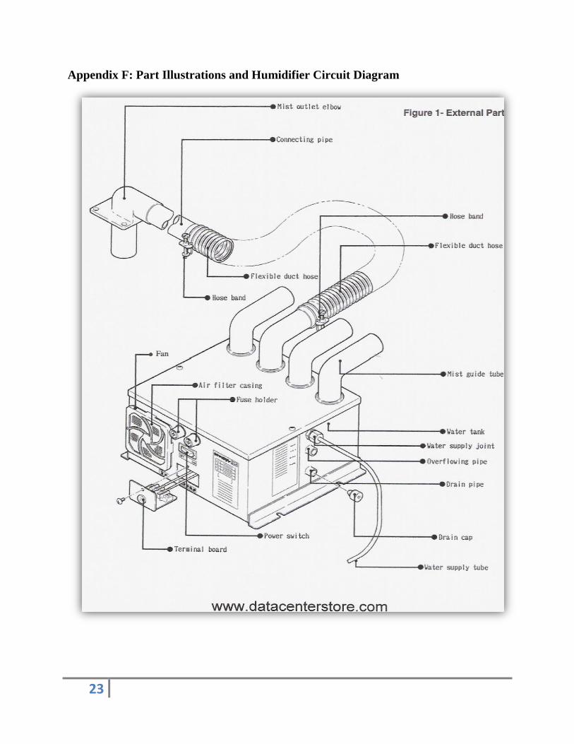
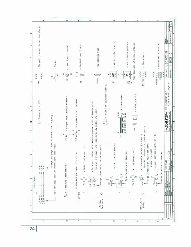
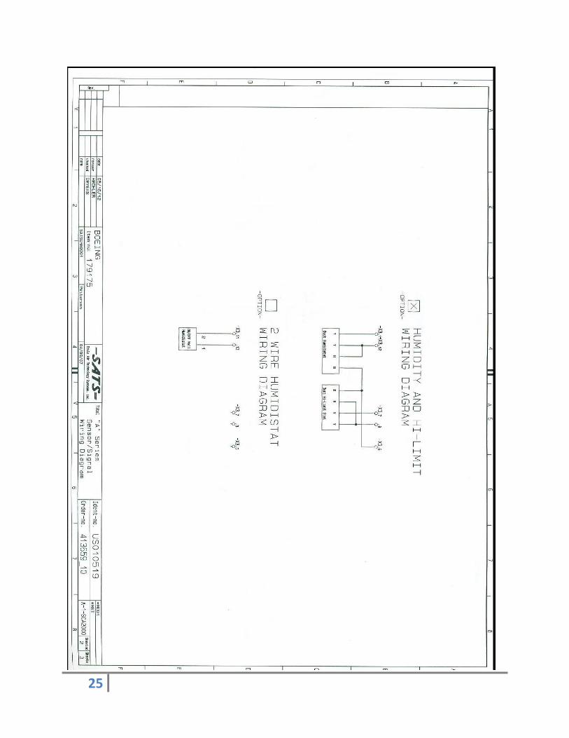
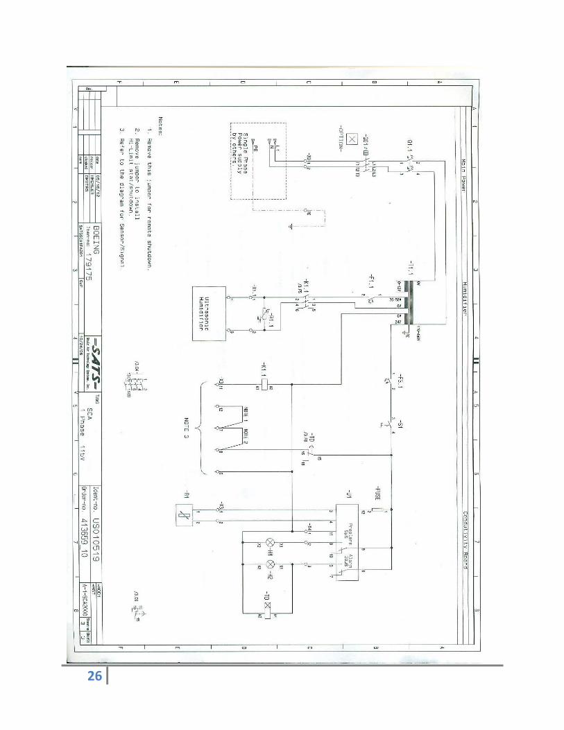
Appendix F: Part Illustrations and Humidifier Circuit Diagram
Page 27
27
Appendix G: References
1. DRI-STEEM. 1 Jan. 2012. 7 Mar. 2012 <http://www.dristeem.com/home>.
2. Incropera, Frank P., and Frank P. Incropera. Fundamentals of Heat and Mass Transfer.
Hoboken, NJ: John Wiley, 2007. Print.
3. "The Boeing Company." The Boeing Company. Web. 08 Mar. 2012.
<http://www.boeing.com/
4. "POYAM VALVES: General Service Valve Range: Gate Valves." POYAM VALVES. Web.
08 Mar. 2012. <http://www.poyam.com/english/products/general/gate_valve.php>.
5. "Sensor Selection Guides." Watlow. Web. 08 Mar. 2012.
http://www.watlow.com/products/guides/sensor/index.cfm
Page 28
28
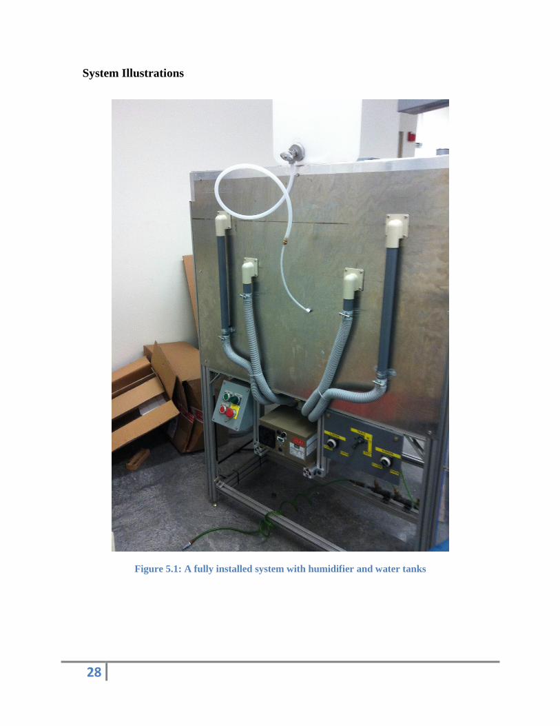
System Illustrations
Figure 5.1: A fully installed system with humidifier and water tanks