+ All Categories
Home > Documents > HUMITECH II plus

HUMITECH II plus

Date post: 19-Nov-2021
Category:
Upload: others
View: 3 times
Download: 0 times
Share this document with a friend
2
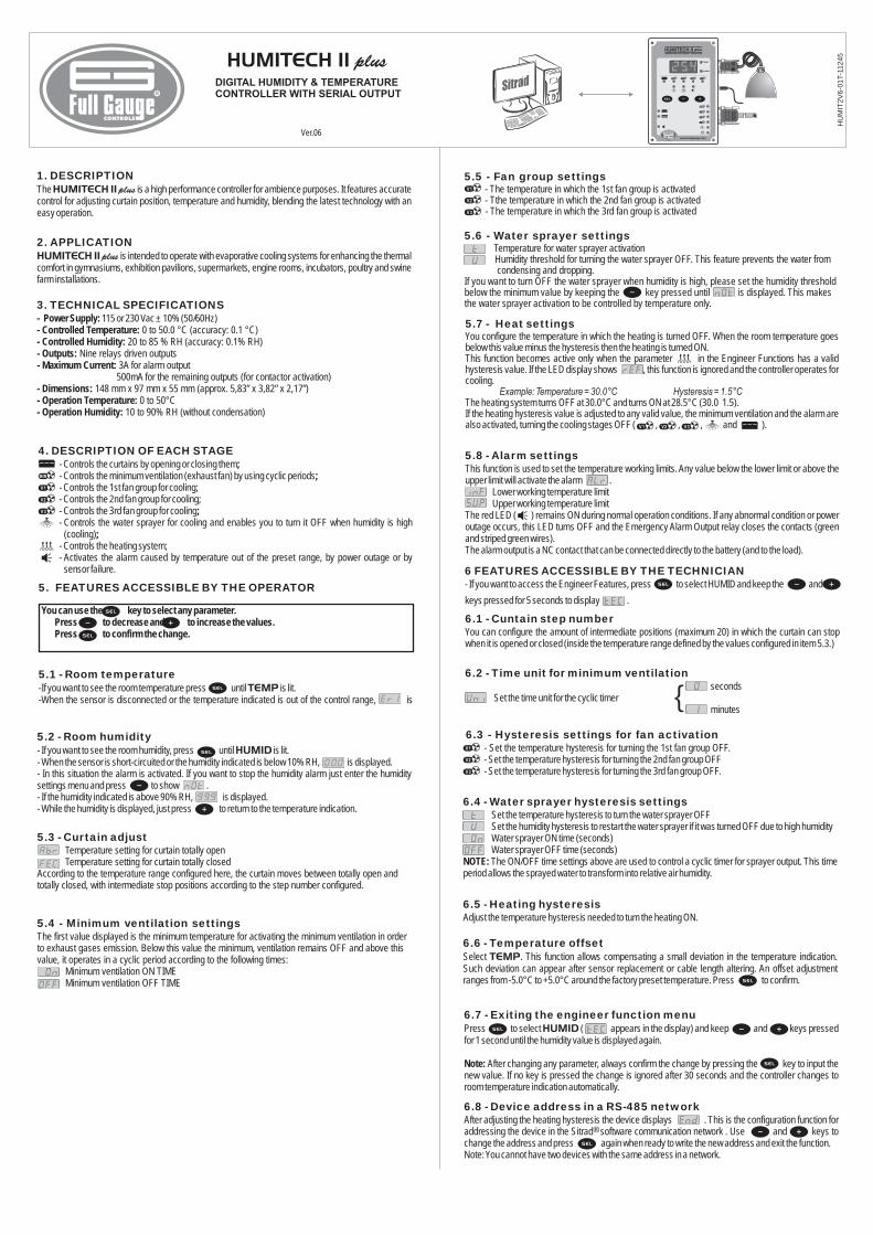
DIGITAL HUMIDITY & TEMPERATURE CONTROLLER WITH SERIAL OUTPUT Ver.06 HUMITECH II plus HUMIT2V6-01T -11245 1. DESCRIPTION 2. APPLICATION 3. TECHNICAL SPECIFICATIONS is a high performance controller for ambience purposes. It features accurate control for adjusting curtain position, temperature and humidity, blending the latest technology with an easy operation. is intended to operate with evaporative cooling systems for enhancing the thermal comfort in gymnasiums, exhibition pavilions, supermarkets, engine rooms, incubators, poultry and swine farm installations. 115 or 230 Vac ± 10% (50/60Hz) 0 to 50.0 °C (accuracy: 0.1 °C) 20 to 85 % RH (accuracy: 0.1% RH) Nine relays driven outputs 3A for alarm output 500mA for the remaining outputs (for contactor activation) 148 mm x 97 mm x 55 mm (approx. 5,83” x 3,82” x 2,17”) 0 to 50°C 10 to 90% RH (without condensation) HUMITECH II plus - Power Supply: - Controlled Temperature: - Controlled Humidity: - Outputs: - Maximum Current: - Dimensions: - Operation Temperature: - Operation Humidity: The HUMITECH II plus 5.2 - Room humidity 5.3 - Curtain adjust 5.4 - Minimum ventilation settings - If you want to see the room humidity, press until is lit. - When the sensor is short-circuited or the humidity indicated is below 10% RH, is displayed. - In this situation the alarm is activated. If you want to stop the humidity alarm just enter the humidity settings menu and press to show . - If the humidity indicated is above 90% RH, is displayed. - While the humidity is displayed, just press to return to the temperature indication. Temperature setting for curtain totally open Temperature setting for curtain totally closed According to the temperature range configured here, the curtain moves between totally open and totally closed, with intermediate stop positions according to the step number configured. The first value displayed is the minimum temperature for activating the minimum ventilation in order to exhaust gases emission. Below this value the minimum, ventilation remains OFF and above this value, it operates in a cyclic period according to the following times: Minimum ventilation ON TIME Minimum ventilation OFF TIME HUMID 5.5 - Fan group settings Water sprayer settings - The temperature in which the 1st fan group is activated - Tthe temperature in which the 2nd fan group is activated - The temperature in which the 3rd fan group is activated Temperature for water sprayer activation Humidity threshold for turning the water sprayer OFF. This feature prevents the water from condensing and dropping. If you want to turn OFF the water sprayer when humidity is high, please set the humidity threshold below the minimum value by keeping the key pressed until is displayed. This makes the water sprayer activation to be controlled by temperature only. 5.6 - 5.7 - Heat settings You configure the temperature in which the heating is turned OFF. When the room temperature goes below this value minus the hysteresis then the heating is turned ON. This function becomes active only when the parameter in the Engineer Functions has a valid hysteresis value. If the LED display shows , this function is ignored and the controller operates for cooling. The heating system turns OFF at 30.0°C and turns ON at 28.5°C (30.0 1.5). If the heating hysteresis value is adjusted to any valid value, the minimum ventilation and the alarm are also activated, turning the cooling stages OFF ( , , , and ). Example:Temperature = 30.0°C Hysteresis = 1.5°C 5.8 - Alarm settings This function is used to set the temperature working limits. Any value below the lower limit or above the upper limit will activate the alarm . Lower working temperature limit Upper working temperature limit The red LED ( ) remains ON during normal operation conditions. If any abnormal condition or power outage occurs, this LED turns OFF and the Emergency Alarm Output relay closes the contacts (green and striped green wires). The alarm output is a NC contact that can be connected directly to the battery (and to the load). 6 FEATURES ACCESSIBLE BY THE TECHNICIAN - If you want to access the Engineer Features, press to select HUMID and keep the and keys pressed for 5 seconds to display . 6.1 - Cuntain step number You can configure the amount of intermediate positions (maximum 20) in which the curtain can stop when it is opened or closed (inside the temperature range defined by the values configured in item 5.3.) Set the time unit for the cyclic timer 6.2 - Time unit for minimum ventilation seconds minutes { 6.4 - Water sprayer hysteresis settings Set the temperature hysteresis to turn the water sprayer OFF Set the humidity hysteresis to restart the water sprayer if it was turned OFF due to high humidity Water sprayer ON time (seconds) Water sprayer OFF time (seconds) The ON/OFF time settings above are used to control a cyclic timer for sprayer output. This time period allows the sprayed water to transform into relative air humidity. NOTE: 6.5 - Heating hysteresis 6.6 - Temperature offset Adjust the temperature hysteresis needed to turn the heating ON. Select . This function allows compensating a small deviation in the temperature indication. Such deviation can appear after sensor replacement or cable length altering. An offset adjustment ranges from -5.0°C to +5.0°C around the factory preset temperature. Press to confirm. TEMP 6.3 - Hysteresis settings for fan activation - Set the temperature hysteresis for turning the 1st fan group OFF. - Set the temperature hysteresis for turning the 2nd fan group OFF - Set the temperature hysteresis for turning the 3rd fan group OFF. 6.7 - Exiting the engineer function menu 6.8 - Device address in a RS-485 network Press to select ( appears in the display) and keep and keys pressed for 1 second until the humidity value is displayed again. After changing any parameter, always confirm the change by pressing the key to input the new value. If no key is pressed the change is ignored after 30 seconds and the controller changes to room temperature indication automatically. After adjusting the heating hysteresis the device displays . This is the configuration function for addressing the device in the Sitrad software communication network . Use and keys to change the address and press again when ready to write the new address and exit the function. Note: You cannot have two devices with the same address in a network. HUMID Note: ® 4. DESCRIPTION OF EACH STAGE ; ; ; ; - Controls the curtains by opening or closing them - Controls the minimum ventilation (exhaust fan) by using cyclic periods - Controls the 1st fan group for cooling; - Controls the 2nd fan group for cooling; - Controls the 3rd fan group for cooling - Controls the water sprayer for cooling and enables you to turn it OFF when humidity is high - Controls the heating system; - Activates the alarm caused by temperature out of the preset range, by power outage or by sensor failure. (cooling) You can use the key to select any parameter. Press to decrease and to increase the values. Press to confirm the change. 5. FEATURES ACCESSIBLE BY THE OPERATOR 5.1 - Room temperature -If you want to see the room temperature press until is lit. -When the sensor is disconnected or the temperature indicated is out of the control range, is TEMP
Transcript

DIGITAL HUMIDITY & TEMPERATURECONTROLLER WITH SERIAL OUTPUT

Ver.06

HUMITECH II plus

HU

MIT

2V

6-0

1T

-11

24

5

1. DESCRIPTION

2. APPLICATION

3. TECHNICAL SPECIFICATIONS

is a high performance controller for ambience purposes. It features accuratecontrol for adjusting curtain position, temperature and humidity, blending the latest technology with aneasy operation.

is intended to operate with evaporative cooling systems for enhancing the thermalcomfort in gymnasiums, exhibition pavilions, supermarkets, engine rooms, incubators, poultry and swinefarm installations.

115 or 230 Vac ± 10% (50/60Hz)0 to 50.0 °C (accuracy: 0.1 °C)

20 to 85 % RH (accuracy: 0.1% RH)Nine relays driven outputs

3A for alarm output500mA for the remaining outputs (for contactor activation)

148 mm x 97 mm x 55 mm (approx. 5,83” x 3,82” x 2,17”)0 to 50°C

10 to 90% RH (without condensation)

HUMITECH II plus

- Power Supply:- Controlled Temperature:- Controlled Humidity:- Outputs:- Maximum Current:

- Dimensions:- Operation Temperature:- Operation Humidity:

The HUMITECH II plus

5.2 - Room humidity

5.3 - Curtain adjust

5.4 - Minimum ventilation settings

- If you want to see the room humidity, press until is lit.- When the sensor is short-circuited or the humidity indicated is below 10% RH, is displayed.- In this situation the alarm is activated. If you want to stop the humidity alarm just enter the humiditysettings menu and press to show .- If the humidity indicated is above 90% RH, is displayed.- While the humidity is displayed, just press to return to the temperature indication.

Temperature setting for curtain totally openTemperature setting for curtain totally closed

According to the temperature range configured here, the curtain moves between totally open andtotally closed, with intermediate stop positions according to the step number configured.

The first value displayed is the minimum temperature for activating the minimum ventilation in orderto exhaust gases emission. Below this value the minimum, ventilation remains OFF and above thisvalue, it operates in a cyclic period according to the following times:

Minimum ventilation ON TIMEMinimum ventilation OFF TIME

HUMID

5.5 - Fan group settings

Water sprayer settings

- The temperature in which the 1st fan group is activated- Tthe temperature in which the 2nd fan group is activated- The temperature in which the 3rd fan group is activated

Temperature for water sprayer activationHumidity threshold for turning the water sprayer OFF. This feature prevents the water fromcondensing and dropping.

If you want to turn OFF the water sprayer when humidity is high, please set the humidity thresholdbelow the minimum value by keeping the key pressed until is displayed. This makesthe water sprayer activation to be controlled by temperature only.

5.6 -

5.7 - Heat settingsYou configure the temperature in which the heating is turned OFF. When the room temperature goesbelow this value minus the hysteresis then the heating is turned ON.This function becomes active only when the parameter in the Engineer Functions has a validhysteresis value. If the LED display shows , this function is ignored and the controller operates forcooling.

The heating system turns OFF at 30.0°C and turns ON at 28.5°C (30.0 1.5).If the heating hysteresis value is adjusted to any valid value, the minimum ventilation and the alarm arealso activated, turning the cooling stages OFF ( , , , and ).

Example: Temperature = 30.0°C Hysteresis = 1.5°C

5.8 - Alarm settingsThis function is used to set the temperature working limits. Any value below the lower limit or above theupper limit will activate the alarm .

Lower working temperature limitUpper working temperature limit

The red LED ( ) remains ON during normal operation conditions. If any abnormal condition or poweroutage occurs, this LED turns OFF and the Emergency Alarm Output relay closes the contacts (greenand striped green wires).The alarm output is a NC contact that can be connected directly to the battery (and to the load).

6 FEATURES ACCESSIBLE BY THE TECHNICIAN- If you want to access the Engineer Features, press to select HUMID and keep the and

keys pressed for 5 seconds to display .

6.1 - Cuntain step numberYou can configure the amount of intermediate positions (maximum 20) in which the curtain can stopwhen it is opened or closed (inside the temperature range defined by the values configured in item 5.3.)

Set the time unit for the cyclic timer

6.2 - Time unit for minimum ventilationseconds

minutes{

6.4 - Water sprayer hysteresis settingsSet the temperature hysteresis to turn the water sprayer OFFSet the humidity hysteresis to restart the water sprayer if it was turned OFF due to high humidityWater sprayer ON time (seconds)Water sprayer OFF time (seconds)The ON/OFF time settings above are used to control a cyclic timer for sprayer output. This time

period allows the sprayed water to transform into relative air humidity.NOTE:

6.5 - Heating hysteresis

6.6 - Temperature offset

Adjust the temperature hysteresis needed to turn the heating ON.

Select . This function allows compensating a small deviation in the temperature indication.Such deviation can appear after sensor replacement or cable length altering. An offset adjustmentranges from -5.0°C to +5.0°C around the factory preset temperature. Press to confirm.

TEMP

6.3 - Hysteresis settings for fan activation- Set the temperature hysteresis for turning the 1st fan group OFF.- Set the temperature hysteresis for turning the 2nd fan group OFF- Set the temperature hysteresis for turning the 3rd fan group OFF.

6.7 - Exiting the engineer function menu

6.8 - Device address in a RS-485 network

Press to select ( appears in the display) and keep and keys pressedfor 1 second until the humidity value is displayed again.

After changing any parameter, always confirm the change by pressing the key to input thenew value. If no key is pressed the change is ignored after 30 seconds and the controller changes toroom temperature indication automatically.

After adjusting the heating hysteresis the device displays . This is the configuration function foraddressing the device in the Sitrad software communication network . Use and keys tochange the address and press again when ready to write the new address and exit the function.Note: You cannot have two devices with the same address in a network.

HUMID

Note:

®

4. DESCRIPTION OF EACH STAGE

;;

;

;

- Controls the curtains by opening or closing them- Controls the minimum ventilation (exhaust fan) by using cyclic periods- Controls the 1st fan group for cooling;- Controls the 2nd fan group for cooling;- Controls the 3rd fan group for cooling- Controls the water sprayer for cooling and enables you to turn it OFF when humidity is high

- Controls the heating system;- Activates the alarm caused by temperature out of the preset range, by power outage or bysensor failure.

(cooling)

You can use the key to select any parameter.Press to decrease and to increase the values.Press to confirm the change.

5. FEATURES ACCESSIBLE BY THE OPERATOR

5.1 - Room temperature

-If you want to see the room temperature press until is lit.-When the sensor is disconnected or the temperature indicated is out of the control range, is

TEMP

9.1 - Electric connection identification

Black and gray:Black and striped black:Striped blue:White:Orange:Blue:Violet:Yellow:Green:Striped green:Brown:Striped brown:Red:Striped red:NOTE:

Cable with plug for serial communicationRed:Black:

For 115Vac power supply (50/60Hz)For 230Vac power supply (50/60Hz)

Output for minimum ventilationOutput for the 1st fan group

Output for the 2nd fan groupOutput for the 3rd fan groupOutput for water sprayerOutput for heating systemOutput for emergency alarm NC dry contact

Output for emergency alarm NC dry contactOutput for controlling the curtain position (open)

Output for controlling the curtain position (close)Potentiometer (+)

Potentiometer (-)The black wire is also the output common wire (exception: alarm output)

AB

NOTES: 1.2.

The loads must be activated through contactor.To enhance the immunity against electromagnetic interference, we recommend the use of arresters and

filters connected in parallel with the contactors winding.

RS485

Serial interfaceRS-485

Full GaugeRS485

®

Integrating Controllers, RS-485 Serial Interface and Computer

A A

B B

A B

A A

B B

A B

Externalmesh

terminal grounded

RS-485 Serial Interface

®

Device used to establish theconnection Full Gauge Controls’instruments with the Sitrad .

Distribution BoxUsed to connect more than one instrument to the Interface. The wire'sconnections must be made in agreement with the following rules: terminal

of the instrument connects to the terminal of the distribution box, thatmust be connected with the terminal of the Interface. Repeat the actionfor terminals and , being the cable shield.

A AA

BThe distributor box terminal is not connected on this instrument.

Serial communicationRS-485

Instrument

Plug

Note: The length of the sensor cable may be increased by the user up to 200 meters, using a 5 x 22AWG

cable.

IMPORTANT

1:2:

3:

According to the chapters from the IEC60364 standard:Install on power supplySensor cables and computer signals can be together, however not at the same place where power

supply and load wires pass forInstall suppresor of transient in parallel to loads to increase the usefull life of the relays

protectors against over voltage

For more information contact our application eng. department through e-mailor dial +55 51 3475.3308.support@ fullgauge.com

Wiring diagram of suppresors in contactors

Sup

pres

or

A1

A2

A1 e A2 are thecontactor coils.

7.1 - Operation description

Configuration Settings

7.2.1 - Control temperature

7.2.2 - Step number

HUMITECH II plus has two outputs to move the curtains. They open and close the curtains tocontrol the temperature inside a poultry shed. One input is used for the position sensor (potentiometer)which informs the controller the curtain position.

The temperature range for controlling the curtain must be configured first. The curtain control willactuate as described in item 5.3.

The step number is the amount of positions you make available for stopping the curtain in anintermediate stand between totally closed and totally open. If the step number is 4, the gradationscale for opening the curtains will be:

7.2 -

7. ELECTRIC COURTAIN ACTIVATION

0%

25%

50%

75%

100%

0

1

2

3

4

Setting the position calibration is very important for the curtain control system correct operation.This procedure uses a potentiometer for sensing the position to inform the controller whetherthe curtains are totally open or totally closed (0 Volts).See the standard installation chart below for understanding the whole operation:

7.2.3 - Potentiometer calibration (curtain 100% open)

Curtains

Contactor

Red

Striped red

Electric motor

Brown (opening)

Striped brown (closing)

Potenciometer1k

You must use a multi-turn 1k ohm potentiometerOutput for opening the curtains

Output for closing the curtainsAs you can see in the figure above the potentiometer is mechanically coupled to the motor shaft (orreduction gear) in such a way that the curtain motion rotates the potentiometer shaft and changesits resistance value. The coupling condition must be good enough to prevent the potentiometershaft from “sliding” (not rotating) during the curtain motion.

a) Close the curtain totally and adjust the potentiometer to the minimum value (0 Volts)B) Turn the crank manually to open the curtains

C) Select the temperature indication ( led on) and keep the and keyspressed.For 15 seconds to display .

The calibration is finished when you release the keys. The controller understands this position as“curtain totally open”.

Brown wire -Striped brown wire -

TEMP

8. PARTS IDENTIFICATION

010203040506

- LED display (screen)- Temperature indication LED- Stage operation LED's- Power supply and control outputs- Setting keys- Configuration process LED's

- Relative humidity indication LED- ON/OFF switch- Fuse (1A)- Humidity and temperature sensors- Plastic hood for outer sensors

Serial communication (RS-485)

070809101112 -

The porous white bulb of thesensor has thread and can beremoved for cleanness. Forthis uses a soft brush, waterand neutral soap.

0707

02

08

01

04

09

11

10

12

0303

05

06

9. WIRING DIAGRAMPower supply

0

115Vac

230Vac

Contactor 1

White

Gray

Striped blue

Striped black

Minimum

ventilation

Black

SerialInterfaceRS-485

Full Gauge

Contactor 2

Contactor 3

Contactor 4

Contactor 5

Contactor 6

Contactor 8

Controller

Orange

Blue

Violet

Green

Striped green

Yellow

Brown

Striped brown

Red

Striped red

Black

Red

Contactor 7

Potenciometer1K

1st fans

group

Water sprayer

2nd fans

group

3rd fans

group

Heating

system

Alarm

Curtains position

(open)

Curtains position

(close)

Serialcomunication cable

RS485

! !

Only connect the power cord plug and thecontrol output wires with device unpowered[power switch turned OFF].

CAUTION

Battery


Recommended