DESIGN AND ANALYSIS OF REMOTE MONITORING AND TESTING OF TELEPHONE FOR HIGHWAYS Hushairi Zen A thesis submitted in fulfillment of the requirements for the award of the degree of Master of Engineering Universiti Malaysia Sarawak 2001
Transcript
DESIGN AND ANALYSIS OF REMOTE MONITORING AND TESTING OFTELEPHONE FOR HIGHWAYS
Hushairi Zen
A thesis submitted in fulfillment of the requirements for the award of the degree of Masterof Engineering
Universiti Malaysia Sarawak
2001
Dedicated to my wife, Dyg. Siti Rahayu and my lovely daughters Nur Hidayah, Nur Adilla, Farah Asyikin, Natasha Amira and Elvy Nurdalila.
Acknowledgement
During the course of this research, I have received the assistance of many people to whom I am very grateful.
First and foremost, I want to thank my project supervisor, Prof. Madya Dr. Mohamad Kadim Suaidi and co-supervisor Encik Al-Khalid Othman, for giving me their support and advice throughout the studies in UNIMAS. Their patience and guidance throughout my thesis project is greatly appreciated. I am greatly indebted with them and this thesis is an acknowledgement of their tenacity and confidence in me. Thank you.
I would also like to thank lecturers in Electronic and Telecommunications Engineering Program, namely Mr. Ng Liang Yew, Dr. Idwar Baharuddin and others who have offered their advice during the course of my research and also helped me directly or indirectly in my thesis project. Their advice and help was especially helpful in improving my thesis.
This thesis would have been very different without the help of my friends and colleagues including Laboratory Assistance, Mr. Zakaria Idris and Mr. Wan Abu Bakar Ngah and also all the administration staffs of Faculty of Engineering, UNIMAS.
Finally, I would like to extend my gratitude to Syarikat Telekom Malaysia Berhad(STMB), R & D Department, Syarikat Telekom Malaysia Berhad and Universiti Putra Malaysia (UPM), Projek Lebuhraya Utara Selatan (PLUS), PERNEC Sdn. Bhd. and Payphone Department, Syarikat Telekom Malaysia Berhad (STMB) for giving me full support during my visit for the research survey.
Abstract
Telephone that serve as special purpose public telephone such as on highways, bridges, tunnels, airfields, military establishment, harbors and large factory installation are normally situated remotely from maintenance office where technicians are placed. Testing and monitoring the operability of every telephone is very expensive and time consuming. Beside the high cost, technicians working in remote areas such as highways are exposed to danger from high-speed vehicles.
Remote monitoring and testing capabilities of this telephone will save time, man-power and therefore save cost. Unfortunately telephones that are equipped with this technology are very expensive. This is because of the complicated circuitry's that are applied in this technology.
Using low cost devices such as digital logic circuits, a telephone system that have similar remote monitoring and testing capabilities is designed. This thesis presents a design of a circuitry that enables highway telephones to be tested and monitored from remote offices. Research survey on remote monitoring and testing of telephone system for highways and its roles in providing road users in time of emergencies are also discussed.
Abstrak
Telefon yang digunakan sebagai alat komunikasi khas seperti yang terdapat di lebuhraya, jambatan, terowong, kawasan tentera, pelabuhan dan kilang yang luas biasanya terletak jauh dari pejabat penyelenggaraan dimana juruteknik ditugaskan. Menguji dan memantau tiap- tiap telefon adalah mahal dan menghabiskan banyak masa. Selain daripada itu, juruteknik yang bertugas di kawasan terpencil seperti di lebuhraya terdedah kepada bahaya kenderaan yang bergerak dengan pantas.
Keupayaan pengujian dari jarak jauh kerosakan telefon akan menjimatkan masa, tenaga kerja dan seterusnya kos. Tetapi malang sekali telefon-telefon yang dilengkapkan dengan teknologi seperti ini terlalu mahal. Ini adalah kerana penggunaan litar-litar yang komplek dan canggih.
Dengan menggunakan komponen-komponen elektronik murah seperti litar logik, sistem telefon yang mempunyai ciri-ciri pemantaun dan pengujian jarak jauh boleh direka. Tesis ini mengutarakan rekaan litar yang membolehkan telefon lebuhraya diuji dan dipantau kerosakannya dari jarak jauh. Penyelidikan mengenai sistem pemantaun jarak jauh untuk lebuhraya juga dibuat dan peranan-peranannya kepada pengguna lebuhraya semasa kecemasan juga dibincangkan.
Table of Contents
Page
Acknowledgement Abstract Abstrak Table of Contents List of Figures List of Tables Abbreviations
Chapter 1 INTRODUCTION
1.1 Overview 1.2 Research Goals 1.3 Thesis Structure
Chapter 2 LITERATURE REVIEW
2.1 Introduction 2.2 The Transmission Medium
2.2.1 Line frequency responds 2.2.2 Telephone line specifications 2.2.3 Telephone line loading coils 2.2.4 Effect of loop length on telephone electrical
parameters 2.2.5 The telephone circuitry 2.2.6 How telephone works 2.2.7 Switch hook 2.2.8 Dialing 2.2.9 Tone dialing 2.2.10 Tone generation 2.2.11 Tone detection 2.2.12 Coupling the DTMF generator to the line 2.2.13 Transmitter and receiver 2.2.14 Ringer circuit
2.3 The Central Office 2.3.1 Battery 2.3.2 Overvoltage 2.3.3 Ringing 2.3.4 Supervision 2.3.5 Coding 2.3.6 Hybrid
2.4 Digital Logic Components 2.4.1 Shift registers 2.4.2 Series-loading shift registers 2.4.3 Digital counters
Chapter 3 RESEARCH SURVEY
Chapter 4
Chapter 5
Introduction Objectives Methodology 3.3.1 PERNEC IPM Sdn. Bhd. 3.3.2 Projek Lebuhraya Utara Selatan (PLUS) 3.3.3 R&D Department, Syarikat Telekom Malaysia
Berhad and Universiti Putra Malaysia (UPM) 3.3.4 Payphone Department, Syarikat Telekom Malaysia
Berhad (STMB) Results and Conclusions 3.4.1 Technology used on Malaysia highways 3.4.2 Faults on emergency telephone 3.4.3 Highway requirements
DIAGNOSTIC METHODOLOGY
Introduction 3 3 The Test Method 33 4.2.1 Loop check (or detect) after a set period of time 33 4.2.2 Loop detect with microphone check after
a period of time 34 4.2.3 Self-test after a period of time 34 4.2.4 Self-test with artificial ring cadence 34 4.2.5 Self-test with different ring cadence 34 Conclusion 36
CIRCUIT DESIGN
Introduction Control Circuit 5.2.1 Delay circuit 5.2.2 Counter circuit 5.2.3 Circuit for driving shift register 5.2.4 Sending telephone electronically off-hook 5.2.5 Counting duration of the self-test 5.2.6 Signal triggering circuitry 5.2.7 Logical gates 5.2.8 Switching telephone off-hook DC Bias and Clock Pulse 5.3.1 Stepping down the ringing voltage 5.3.2 Digital components supply voltage 5.3.3 Regulating the voltage 5.3.4 Supplying power to logic components Self-Test Circuit 5.4.1 Receiving and generating the test signal 5.4.2 Testing the telephone circuitry
Chapter 6
Chapter 7
References
RESULTS AND DISCUSSIONS
Introduction Simulation Results 6.2.1 Clocking and bias circuit 6.2.2 Control circuit
Overview of remote monitoring and testing of highway telephone system Measuring DC resistance using ohmmeter Typical frequency response of a telephone line Simplified telephone transmitter Dial circuit with switch hooks closed Rotary dial Push button keypad DTMF circuit DTMF sending level specifications An electromagnetic transducer Piezoelectric Typical analog telephone connection Typical central office battery feed-capacitance Coupled A series-loading shift register A SIP0 shift-right register D flip-flop connected as a shift register Communication chain in north-south highways Normal ringing cadence Ring cadence in self-test mode Block diagram of the test and monitoring circuit in the telephone Status of 413 and Q14 after 8 sec and 16 sec respectively Time of self-test Input and output waveform of Hex Schmitt trigger Voltage of C6 in normal ringing operation Voltage of C6 in self-test operation Configuration pins of TCM3 105 modem chip Block diagram of FX604 modem chip
The RL dB gain for different impedance Central office battery feed Truth table for series-loading shift register Truth table for SIP0 shift-right register Average percentage breakdown of failures in 1998 Breakdown on type of failures Functions of each circuitry Truth table for CD4015B Recommended operating conditions Truth table for MC14060B counter Maximum ratings for MC14060B Maximum ratings for MC14013B Truth table for MC14013B Maximum ratings for MC14106B Hex Schmitt trigger Functions of each inverter Maximum rating of LM317L voltage regulator
Page
15 18 21 23 3 1 3 1 38 40 40 42 43 43 44 46 47 52
Abbreviations
PC PBX DC AWG AC ISDN DTMF RL SISO SIP0 FF IC ETOCE LICE RCC ATE MOS WVDC
Personal Computer Private Branch Exchange Direct Current American Wire Group Alternate Current Integrated Services Digital Network Dual Tone Multiple Frequency Return Loss Series In Series Out Series In Parallel Out Flip-Flop Integrated Circuit Emergency Telephone Outstation Control Equipment Line Interfacing Controlling Equipment Regional Communication Center Automatic Test Equipment Metal Oxide Semiconductor Working Volts DC
Chapter 1
INTRODUCTION
1.1 Overview Telephones that serve as special purpose emergency telephone such as on bridges, highways, tunnels, airfields, military establishment, harbors and large factory installation are normally situated remotely from maintenance office where technicians are placed. To check the operability of every telephone, technicians need to go to every site for testing. This is time consuming and waste of man-power and therefore uneconomical. Most of the time is spent by the technicians on the road, on the journey to the sites rather than maintaining the telephones. News release by Highways Agency on 6" October 2000 had shown that maintenance man-power has been reduced by halves when remote monitoring capability was installed.
T o cover large number of telephones, more technicians are needed. As a result, high cost of testing and maintenance are face by the organizations that provide these services.
Another aspect is the safety of technicians working in remote areas, as emergency telephones on highways, tunnels and bridges are normally situated close to roads, and they are exposed to danger from high-speed vehicles. Parking spaces are normally not available at these sites and this may disturb the flow of traffics and cause traffic jam.
Remote testing and monitoring of these telephones will save time, manpower and therefore save cost. Technicians do not have to visit telephone sites to do testing and monitoring works and large number of telephones can be tested for a short duration of time. Technicians need only to visit telephone sites that are confirmed faulty by testing and monitoring devices at the central office.
1.2 Research Goals The objective of this project is to design a circuitry that will enable self-testing and monitoring the operability of the telephone set using low cost electronics devices. When this circuitry is install in the telephone set, it will allows a PC from remote offices to carry out testing and monitoring the telephone operability status. Research on telephone system in Malaysia including highway emergency telephones and public payphones are carried out.
The main concept of this design is to enable "emergency telephones" on highways to he monitored or tested either by telephone or PC that is located in main office, a distance away from the remote office. The circuitry to be designed will be placed inside the emergency telephone and will test the operability of the telephone when requested by technicianloperator from central office. This circuitry will be able to detect whether the call placed by the caller is an ordinary call or a test call. When ordinary call is made, the telephone will work like ordinary telephone set and when test call is made it will activate the testing procedures. Calling is done similar to ordinary telephone system and it follows the same basic protocols when dialing and terminating a call. The remote monitoring and self- testing telephone can be tested either by using ordinary telephone set or a PC in a remote office.
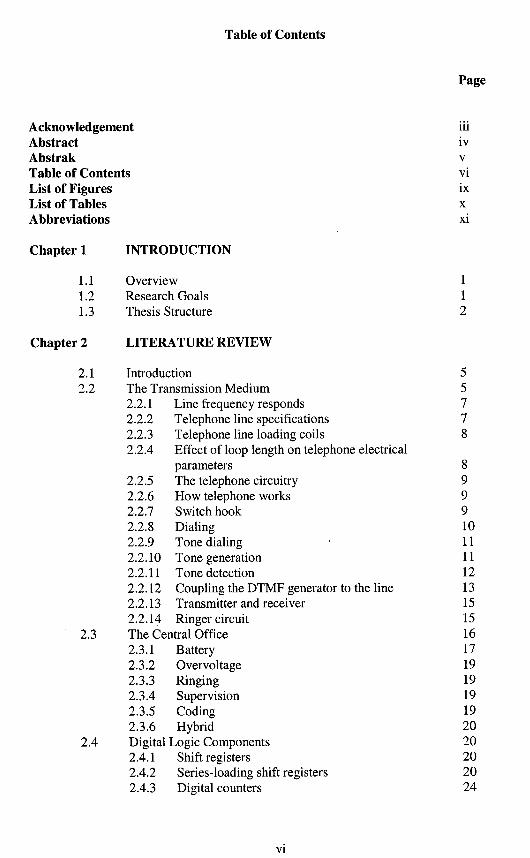
Public sw ,oh
Telephones
PC-MODEM
Figure 1.1 Overview of remote monitoring and testing of highway telephone system
Overview of the remote monitoring and testing of telephone system is shown in Figure 1.1. The main idea is to have a PC located in main office to test and monitor the operability of highway telephones in remote location. The highway telephones are connected to either a Private Branch Exchange (PBX) or Public Branch Exchange. Connection is done using optic cables because of the distance between highway telephones and PBX is normally very far. PBX is connected to PC through a modem using copper as the distance between PBX and PC is maintained at less than 5 km.
1.3 Thesis Structure This thesis covers the following topics:
Chapter 2: Literature review on the telephone technology. The literature review on telephone technology covers topics on telephone set, the exchange office and the local loop. The important characteristics of these topics are discussed, as they might be important in designing the remote monitoring and testing circuitry. The parameters and electrical properties of the telephone set circuitry are also covered.
Chapter 3: Research surveys. The research survey discussed the research that has been done during visits to relevant organization such as Projek Lebuhraya Selatan (PLUS), Research and Development Department, Syarikat Telekom Malaysia (UT'M-MTDC), Syarikat Telekom Malaysia Bhd (Sarawak), Payphone Department, Syarikat Telekom Malaysia Bhd and PERNEC IPM Sdn Bhd. The results of the survey are presented.
Chapter 4: Diagnostic methodology. The testing procedures must be identified before a self- testing circuitry is designed. This chapter described the methodology of the test procedures. The chosen test procedures are explained and this includes the normal and the test mode ringing signals. Design analyses of test procedures are also covered.
Chapter 5: Circuit design. This chapter covers 3 main sections, the control circuit, the DC bias and clock pulse circuit and the self-test circuit. The control circuit section discussed the design of the circuitry that enable telephone to identify test ringing tone and place the telephone electronically off-hook. The design considerations and the major components used in the design are discussed. The DC bias and clock pulse section described the circuitry that provides clocking signal and bias voltage to the control circuit. The self-test circuit section explained the circuit that provides test signal to the telephone.
Chapter 6: Results and discussions. This chapter discussed the results of the simulation and experiment. Simulations and cxperiments are done to ensure that the design works perfectly. Simulations are carried out using Micro-Cap 6, a simulation software that allows mixer of analog and digital circuits.
Chapter 7: Conclusions. This final chapter concluded the thesis and recommendation on further works that can he carried out to further improve the circuit designed. Other features that might be important to highway telephones in the future are also included.
Chapter 2
LITERATURE REVIEW
2.1 Introduction The basic telephone system consist of a telephone set, a transmission medium (twisted pair cable) and an exchange office. With these 3 basic components in place it is sufficient to have a normal telephone conversion. The telephone system and telephone set is studied. This includes the parameters and characteristic of the telephone system. The design on the self- testing and monitoring telephone circuit uses digital logic and analog components. Discussions on these topics are also included.
2.2 The Transmission Medium A transmission medium connects the telephone to an exchange office where voice signal is carried to enable communication between two parties. The connection between telephone and exchange office is usually by twisted pair of 0.5 mm copper wires also known as AWG 22. This connection form a complete loop between the telephone and the exchange office and popularly known as "the local loop". Although copper is a good conductor, due to its length it offer some resistance of about 16.46 ohms per thousand feet at 77'F [Macassey, 19951.
Telephone equipment is generally considered to he current driven, so its measurements refer to current consumption, not voltage. The length of the local loop connecting the telephone to the exchange office determine the total resistance of the line and therefor affects the current drawn by the telephone attached at the end of the line.
The voltage applied to the line to drive the telephone is - 48V dc in Malaysia and varies from country to country. This voltage is supplied through the same twisted pair wire that carries the voice signal. The voltage is supplied by lead acid cell, thus assuring a hum-free supply and complete independence from the electric company, which may be useful during power failures.
The DC resistance of a phone or any devices attached to the phone line at the subscriber side is quoted at approximately 200 ohms and in practice vary from 150 to 1000 ohms [Macassey, 19951. The DC resistance can be measured with an ohmmeter as shown in Figure 2.1
Figure 2.1 Measuring DC resistance using ohmmeter
From the resistance value, the distance between the telephone and the exchange can be estimated. The phone line has impedance composed of distributed resistance, capacitance, and inductance. The impedance vary depending on the length of local loop, type of insulation of the wire, and whether the wire is aerial cable, buried cable, or bare parallel wires strung on the telephone poles. For calculation and specification purposes Syarikat Telekom Malaysia Berhad (STMB) normally uses 600 ohms as the nominal value. If the instrument attached to the phone line is of the wrong impedance i.e much more or less than 600 ohms, a mismatch would occur also known as a return loss. A return loss is also known as standing wave ratio, SWR. A mismatch of impedance on telephone lines can results in echo and whistling, which is also known as "singing" and normally occurred with low quality telephones. A mismatch device can be made to match by placing resistors in parallel or series with the line to bring the impedance of the device to the desired limits. This will cause some signal loss, but will reduce the standing wave ratio and make the device usable.
A twisted pair cable telephone line is balanced feed, with each side equally balanced to the ground. Any inbalance will introduce hum and noise to the phone line. The balance of the phone line is known as "longitudinal balance". If both impedance match and balance to ground are kept in mind, any device attached to the phone line will perform well, just as the correct matching of transmission lines and devices will ensure good performance in any electronic principles [Macassey, 19951.
In Malaysia, the two phone wires connected to the phone should be red and green although in some other countries they may be different colours. The red wire is negative and the green wire is positive. The positive green wire is known as "Tip" and the negative red wire "Ring". Besides the red and green pair of wires, there is another pair of yellow and black wires in most installation. These wires can be used for many different purposes although it is seldom used. Some party lines use the yellow wire as a ground and sometimes there is a 6.8V AC on this pair to light the dials of Princess type phones. These extra pair of wires is also used for extra phone carrying a second telephone line in the same house, and is different set-up from extension set-up. In this case black is "Tip" and yellow is "Ring".
The line that connects DC voltage between the subscriber point to the telephone exchange is known as a "metallic line". In metallic line, a "loading coils" which is an inductance devices are sometime placed in the line to alter the frequency response of the line. Other types of lines are party lines, which may be metallic line but require special telephones to allow the telephones company to differentiate between subscribers.
Very long lines may have amplifiers, sometimes called "loop extenders" on them. A subscriber carrier is a RF system in which the telephone signal is heterodyned up to around 100 kHz and then sent along another subscriber's twisted pair.
2.2.1 Line frequency responds Typical telephone line has frequency response 0.3 to 3.4 H z as shown in Figure 2.2 [Bigelow, 19931. The signal starts to attenuate in the frequencies below 300 Hz because of the AC coupling of audio signals (audio signal goes through capacitors and transformers). The transformer and the available bandwidth limit the high frequency response in the telephone transmission system.
Figure 2.2 Typical frequency response of a telephone line [Bigelow, 19931
The frequency response above is for a typical good telephone line. In real life situations the high and low frequencies are further attenuated depending on the quality of the line.
b
Voice Channel b
2.2.2 Telephone line specifications Normal telephone line is theoretically designed to be 600 ohms resistive impedance. This 600 ohms is kept as international reference for designing telephone line equipment as the signal powers are typically measured to 600 ohms load [Bigelow, 19931. Nevertheless, different countries used different reference value and in US reference value of 770 ohms is used.
0.3 Frequency (kHz) 3 4
Output Voltage
In practice the telephone line does not behaves as a pure 600 ohms resistance. The cable and equipment used by the telephone companies have an effect on what the real impedance is. Telephone equipment that is designed to operate with 600 ohms load will operate with the actual lines, but its performance is not an ideal situation. Typically the telephone equipment such as modem is designed for 600 ohms reference impedance because they can handle the side-tone, but for the best performance the telephones are designed to the actual line impedance.
4 Voice Bandwidth
b
When the best performance is needed the circuit should be matched to the impedance of the real telephone lines. Matching the hybrid circuit to the characteristic impedance (instead of 600 ohms) will improved the feedback typically between 3 to 6 dB [Miller, 19961.
2.2.3 Telephone line loading coils Loading coils are lumped inductance added in series with the telephone line to compensate for the mutual capacitance of the cable pair(s). They are placed at specific intervals on loops of 5 km or more to improve voice grade transmission. Placing load coils other than at the specified intervals may degrade voice transmission. The upper cut off frequency of the telephone equipment is generally accepted at 3 Hz. Therefore loaded loops do not lend themselves well to high frequency or high data rate transmission. Loading coils introduce phase delays that are acceptable for voice but not for high-speed data and are best confined to very long local voice loops where voice grade transmission needed to be improved. With the advent of ISDN and other high hit rate digital transmission technologies, many telephone companies are attempting to limit loop lengths to 5 km or less to eliminate the need for loading coils [Bigelow, 19931.
2.2.4 Effect of loop length on telephone electrical parameters The resistance of the telephone set is typically around 400 to 900 ohms if measured at points X and Y with local loop disconnected as shown in Figure 2.3. It is made up of R,, and R,,, where R,,,, lumps together the rest of the resistance in the telephone besides R , R,, is the impedance of the transmitter and Recis the impedance for telephone set circuitry.
RL represent the line resistance of both wires. It varies with the length of line to the central office; the longer the line, the larger the resistance. Ohm's law determines the loop current as follows:
Central Ofice Voltage I L =
Rtr + R,,t + RL
where the Central Ofice Voltage is - 48 V
The total resistance in the local loop (R,, + R,, + RL) becomes larger as the line length from the telephone set to the central office increases; therefore, the current becomes smaller. Also, as the total resistance increases, the input resistance, R,, as a percentage of the total resistance decreases. Therefore, for the same speech input, the variation in the local loop
current decreases as the line length increases. This causes the speech level to go down at the called telephone's receiver. This is not a desirable condition and methods to provide automatic compensation for line length have been developed.
It is desirable that the speech on all calls arrives at the exchange at about the same volume or level regardless of loop length. Modern telephone sets have automatic compensation circuit to achieve this. In Figure 2.3, the varistor resistance decreases as loop current increases with shorter loops. This resistance bypasses some of the current around the transmitter so that the varistor automatically adjusts the speech level so that a relatively constant speech level will appear at the exchange regardless of the distance to the telephone set.
2.2.5 The telephone circuitry The telephone set is designed to operate under a wide range of electrical, mechanical, and acoustical conditions. Some of the design parameters are dictated by human factors such as sound pressure levels and handset dimensions. Some are historical carryovers such as ringing voltage and frequency and some as minimum line current for satisfactory carbon transmitter and relay operation are dictated by physical properties of the material used in the telephone set.
Basically the telephone set consist of 5 main parts, the speech network, receiver and transmitter, switch hook, dialer and ringer circuit. It basic operation has not change very much since its discovery and new technologies added to telephone set is merely and add-on device to enhance its services.
2.2.6 How telephone works Telephone sets are simple in appearance and operation and yet it perfor~ns a surprising number of functions. Some of the important functions are:
1. It requests the use of the telephone system when the handset is lifted. 2. It indicates that the system is ready for use by receiving a tone, called dial tone. 3. It sends the number of the telephone to he called to the system. The caller initiates the
numbers when the number is pressed or dial is rotated. 4. It indicates the state of a call in progress by receiving tones indicating the status
(ringing, busy and so on) 5. It indicates the incoming call to the called telephone by ringing bells or other audible
tones. 6. It changes speech of a calling party to electrical signals for transmission to a distant
party through the system. It then changes electrical signals received from a distant party to speech for the called party.
7. It automatically adjusts for changes in the power supplied to it. 8. It signals the system that a call is finished when a caller "hangs-up" the handset.
T o understand better the functions of the telephone, it is essential to understand the functions of all the important components in a telephone set. Some of the important components that need to be understood are the switch hook, the dialing system, transmitter, receiver, ringer and hybrid circuit and electrical parameters that dictate the operation of a telephone set.
2.2.7 Switch hook The switch hook is made up of a simple onloff switch. When the switch is in an open state, it is known as on-hook and off-hook in a close state. When the handset is lifted to make a call, this is known as off-hook where the switch hooks contacts and the switches S1 and S2 are
closed as shown in Figure 2.4. The loop current then flows from the central office battery through the telephone set and through a relay coil at the central office.
Figure 2.4 Dial circuit with switch hooks closed [Bigelow, 19931
Swilch Hook
Hybrid 1 I I
-4.
When sufficient current flows in the relay coil, this relay is energized and closed contacts signal to other central office equipment that a subscriber telephone is off-hook. A line finder than sets up a connection for the switching equipment to begin receiving the telephone number. At this point, a dial tone generator is connected to the line to signal the caller to proceed with dialing. Dialing may be done by pulsing (interrupting) the loop current or by sending audio tones. When the first dialed digit is received at the central office, the dial tone is removed from the line.
S2
TELEPHONE
2.2.8 Dialing There are two types of dialing being used, pulse dialing and tone dialing. Pulse dialing is accomplished with a rotary dial having ten equally spaced finger-holes as shown in Figure 2.5. The number of dial pulses resulting from one operation of the dial is determined by how far the dial is rotated before releasing it.
CENTRAL OFFICE
Figure 2.5 Rotary dial [Bigelow, 19931
The regularly spaced holes in the dial plate and the finger stop make it easy to rotate and dial the correct amount for each digit. This action winds up a spring that rotates the dial back to the rest position when it is released. A small governor inside the dial causes it to return at a constant rate of rotation.
A cam turned by the shaft through a rear operates the switch contact S3, shown in Figure 2.4, which opens and closes the local loop circuit during the return rotation of the dial. (The loop is not broken during forward rotation of the dial). Opening the loop circuit interrupts the loop current flow of 20 to 120 mA and closing the circuit permits the loop current to flow again. Thus pulse dialing produce a series of current pulses in the loop circuit. One pulse is sent for the digit 1, two for the digit 2, and so on, up to ten pulses for the digit 0.
2.2.9 Tone dialing Nowadays, most telephone sets use the method called dual tone multi-frequency (DTMF) for sending a telephone number. These can be used provided the central office is equipped to process the tones.
As shown is Figure 2.6, instead of a rotary dial, these telephone sets are equipped with a push-button keypad with 12 keys represent the numbers 0 through 9 and the symbols * and #.
High Group Frequencies (Hz)
Low Group Frequencies
C1 C2 C3 C4
Figure 2.6 Push button keypad [Bigelow, 19931
Some special purpose telephones have a forth column of keys for a total of 16 keys as shown dotted in Figure 2.6. Pressing one of the keys causes an electronic circuit to generate two tones in the voice band. There is a low frequency tone for each row and a high frequency tone for each column.
The frequencies and the keypad layout have been internationally standardized, but the tolerances on individual frequency may vary in different countries.
2.2.10 Tone generation A DTMF circuit using discrete components is shown in Figure 2.7. Switches S1, S2, and S3 are shown in the inactive position. With the switch-hook in the off-hook position, loop current flows through RV1, LlA, L2A, and via the hybrid network to the line. Transistor Q1 is off. Capacitors C1 and C2 are disconnected at one end by the open contacts of S1 and S2.
Figure 2.7 DTMF circuit [Bigelow, 19931
When a key is pressed, mechanical couplings, called the row rod and column rod, for that position close the appropriate S1 and S2 contacts to connect C1 to a tap on LIA and C2 to a tap on L2A. This establishes the resonant circuits for the required low-group tone (LlA-C1) and high-group tone (L2A-C2).
The mechanical arrangement of the push button and switches is such that the resonant circuit connections just describe are made with only partial depression of the button. At this point, S3 is still in the position shown. Further depression of the button causes S3 to change position. This interrupts the dc flow through LIA and L2A and shock-excites the two resonant circuits into oscillation.
At the time, S3 connects battery voltage from the line to the collector of Q1. The transformer coupling between LIA, LIB, and LlC, and between L2A, L2B, and L2C cause Q1 to sustain the oscillations and modulate the loop current to transmit the two tones to the central office. The transmitter and receiver are shunted when S3 switches, hut the outgoing tones can still be heard in the receiver at a low level.
2.2.11 Tone detection The tones used have been carefully selected so that the processing circuits (called the digit receiver) in the central office will not confuse them with other tones that may occur on the line. The digit receiver has frequency selective filters that pass only the frequencies used for
DTMF. It also has timing circuits which make sure a tone is present for a specified minimum time (about 50 milliseconds) before it is accepted as a valid DTMF tone.
After a connection to an answered phone has been made, the digit receiver is out of the circuit and the DTMF tones can be transmitted the same as the speech. This permits the use of DTMF tones as data communications for entering orders at a remote terminal or obtaining information from a remote database.
2.2.12 Coupling the DTMF generator to the line The requirements for the proper interfacing of the DTMF generator to the line are:
1. The correct dc voltages and loop currents must be maintained on any loop length 2. The tones must have proper amplitude and distortion characteristics. 3. The DTMF generator must have the proper impedance to match the line.
Problems may arise when powering the DTMF circuits from the line in either of the two extreme cases - long loops or short loops. Long loops reduce the amount of current and voltage available for electronic circuits in the telephone; thus, the tone-dialing circuits need to operate from a supply voltage as low as 3 volts. The minimum working dc voltage (VdC,,,,,,) for the DTMF generator and interface circuit will be the sum of the peak voltages of the two tones (VlPx+ Vhp3. the desired regulated (V,e,), and the voltage drop necessary to achieve the regulating voltage (Vbe + V, (,,,) [Bigelow, 19931.
For example:
Short loops require the telephone set to sink (absorb) high loop current or handle high dc voltage if no provision is made at the central office to regulate or limit the current and voltage supplied to the loop. In either case, the interface must maintain proper dc voltage regulation if it is to supply voltage to other circuits.
The sending levels of the DTMF tones are referenced to 0 dBm (1 milliwatt of power dissipated in 600 ohms impedance). The high frequencies have a level 2 dB above the level of the low frequencies to compensate for losses in transmission. Figure 2.8 is the curve usually shown to specify the sending levels of the tone pairs. This curve represents the optimum and maximum differences in the output levels between tone pairs.
Allowable distortion of the transmitted tones is specified in several ways:
1 I I I I I I I I I
The total power of all unwanted frequencies shall be at least 20 dB below the level of the frequency pair that has the lowest level.
-- -1
-- -2 Low -- -3 Frequency -- -4 Level (dBm)
-- -5
-- -6
-- -7
-- -8
-- 9
- -10
The level of unwanted frequency produce by the pair shall be: 1. Not more than -33 dBm in the hand from 0.3 to 3.4 H z . 2. Not more than -33 dBm at 3.4 kHz and failing 12 dB per octave to 50 kHz 3. Not above -80 dB above 50 kHz.
-
Distortion in dB is defined as:
Jv: t v; t ....... + v; Distortion = 20 loglo m where,
V, through VN are the unwanted frequency components V, is the low frequency tone V,, is the high frequency tone
When the DTMF generator is active, it must present the correct dynamic impedance to the loop. Nominal 900 ohms impedance is the requirement. When the DTMF generator is inactive, it must present low dynamic impedance when connected in series with the speech circuit and high dynamic impedance when connected in parallel.