12
Illustrated Parts List 532 43 99-99 FT900 "This machine is approved by the EPA for E10 (10% ethanol) and lower fuel only. Do not use any fuel >E10 in this machine."
Illustrated Parts List
532 43 99-99
FT900
"This machine is approved by the EPA for E10 (10% ethanol) and lower fuel only. Do not use any fuel >E10 in this machine."
18
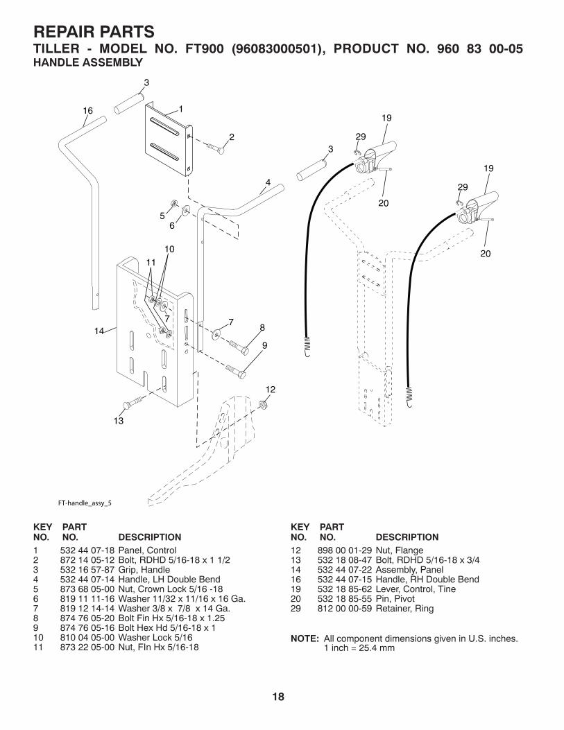
KEY PART NO. NO. DESCRIPTION1 532 44 07-18 Panel, Control2 872 14 05-12 Bolt, RDHD 5/16-18 x 1 1/23 532 16 57-87 Grip, Handle4 532 44 07-14 Handle, LH Double Bend5 873 68 05-00 Nut, Crown Lock 5/16 -186 819 11 11-16 Washer 11/32 x 11/16 x 16 Ga.7 819 12 14-14 Washer 3/8 x 7/8 x 14 Ga.8 874 76 05-20 Bolt Fin Hx 5/16-18 x 1.259 874 76 05-16 Bolt Hex Hd 5/16-18 x 110 810 04 05-00 Washer Lock 5/1611 873 22 05-00 Nut, FIn Hx 5/16-18
KEY PART NO. NO. DESCRIPTION
1
23
3
16
4
56
78
9
12
13
FT-handle_assy_5
147
11
10
29
19
20
29
19
20
NOTE: All component dimensions given in U.S. inches. 1 inch = 25.4 mm
REPAIR PARTSTILLER - MODEL NO. FT900 (96083000501), PRODUCT NO. 960 83 00-05HANDLE ASSEMBLY
12 898 00 01-29 Nut, Flange13 532 18 08-47 Bolt, RDHD 5/16-18 x 3/414 532 44 07-22 Assembly, Panel16 532 44 07-15 Handle, RH Double Bend19 532 18 85-62 Lever, Control, Tine20 532 18 85-55 Pin, Pivot29 812 00 00-59 Retainer, Ring

19
411
2
3
4
5 426 7
829
11
9
17
3130 29
11
11
11
10
14
15
12
12
13
16
19
32
18
2025
2122
23
24
26
2827
belt_guard_14
KEY PART NO. NO. DESCRIPTION
1 532 43 91-62 Assembly, Bracket, Belt Guard 2 532 00 94-84 Clip, Cable3 532 08 67-77 Screw #10-24 x 1/24 874 61 08-12 Bolt, Hex Head 1/2-20 x 3/45 873 68 06-00 Nut, Hex 3/8-166 819 13 13-16 Washer 13/32 x 13/16 x 16 Ga.7 532 00 20-09 Pulley, Idler, Reverse 8 532 18 03-23 Assembly, Arm, Reverse Idler9 874 76 06-28 Bolt, Hex Head 3/8-16 x 1-3/410 532 44 07-09 Guard, Belt 11 819 09 10-16 Washer 9/32 x 5/8 x 16 Ga.12 532 10 42-13 Nut, Cap 1/4- 2013 872 14 04-06 Bolt, Carriage 1/4-20 x 3/414 532 13 30-35 V-Belt (Forward Motion)15 532 00 26-14 V-Belt (Reverse)16 812 00 00-28 Ring, Retainer17 532 00 26-49 Key, Square18 532 15 12-36 Sheave, Transmission "Flat"19 532 18 85-02 Bolt, Belt Guard20 812 00 00-36 Ring, Klip
21 873 35 06-00 Nut, Hex, Jam 3/8-1622 532 16 18-06 Pulley, Idler23 532 17 53-77 Arm, Idler24 874 76 06-20 Bolt 3/8-16 x 1-1/425 532 10 69-68 Shaft, Idler Arm26 873 35 05-00 Nut, Hex, Jam 5/16-1827 873 22 04-00 Nut, Hex 1/4-2028 810 04 04-00 Washer, Lock 1/429 532 10 92-27 Pad, Idler30 823 20 04-04 Screw, Set , Socket, Headless C.P. 1/4-20 x 1/431 532 10 11-89 Sheave, Engine32 532 15 12-23 Sheave, Transmisison41 532 18 03-07 Spring Extension42 532 13 89-09 Spacer
NOTE: All component dimensions given in U.S. inches. 1 inch = 25.4 mm
REPAIR PARTSTILLER - MODEL NO. FT900 (96083000501), PRODUCT NO. 960 83 00-05BELT GUARD AND PULLEY ASSEMBLY
KEY PART NO. NO. DESCRIPTION
20
KEY PART NO. NO. DESCRIPTION
KEY PART NO. NO. DESCRIPTION
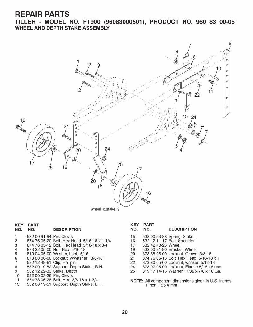
1 532 00 91-94 Pin, Clevis2 874 76 05-20 Bolt, Hex Head 5/16-18 x 1-1/43 874 76 05-12 Bolt, Hex Head 5/16-18 x 3/44 873 22 05-00 Nut, Hex 5/16-18 5 810 04 05-00 Washer, Lock 5/166 873 80 06-00 Locknut, w/washer 3/8-167 532 12 49-61 Clip, Hairpin8 532 00 19-52 Support, Depth Stake, R.H.9 532 12 22-33 Stake, Depth10 532 00 03-26 Pin, Clevis11 874 78 06-28 Bolt, Hex 3/8-16 x 1-3/413 532 00 19-51 Support, Depth Stake, L.H.
15 532 00 53-88 Spring, Stake16 532 12 11-17 Bolt, Shoulder17 532 42 70-25 Wheel19 532 00 91-90 Bracket, Wheel20 873 68 06-00 Locknut, Crown 3/8-1621 874 76 05-16 Bolt, Hex Head 5/16-18 x 122 873 80 05-00 Locknut, w/insert 5/16-1824 873 97 05-00 Locknut, Flange 5/16-18 unc25 819 17 14-16 Washer 17/32 x 7/8 x 16 Ga.
NOTE: All component dimensions given in U.S. inches. 1 inch = 25.4 mm
REPAIR PARTSTILLER - MODEL NO. FT900 (96083000501), PRODUCT NO. 960 83 00-05WHEEL AND DEPTH STAKE ASSEMBLY
21
KEY PART NO. NO. DESCRIPTION
3
1
6
4
56
2
2
tine_ipb_3
KEY PART NO. NO. DESCRIPTION
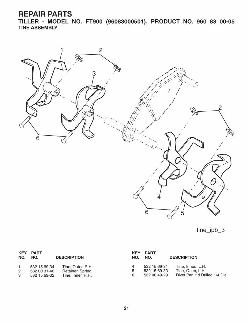
4 532 15 69-31 Tine, Inner, L.H.5 532 15 69-33 Tine, Outer, L.H.6 532 00 49-29 Rivet Pan Hd Drilled 1/4 Dia.
1 532 15 69-34 Tine, Outer, R.H.2 532 00 31-46 Retainer, Spring3 532 15 69-32 Tine, Inner, R.H.
REPAIR PARTSTILLER - MODEL NO. FT900 (96083000501), PRODUCT NO. 960 83 00-05TINE ASSEMBLY

22
KEY PART NO. NO. DESCRIPTION
KEY PART NO. NO. DESCRIPTION
14 532 00 91-73 Spacer, Split16 819 09 14-12 Washer 9/32 x 7/8 x 12 Ga.17 819 09 20-16 Washer 9/32 x 1-1/4 x 16 Ga.18 810 04 04-00 Washer, Lock 1/419 874 61 04-12 Bolt, Hex 1/4-28 x 3/4 Gr. 520 - - - - - Engine Briggs Model 121002-1380-B8
1 874 76 05-24 Bolt, Hex 5/16-18 x 1-1/2 Gr. 22 874 78 06-52 Bolt, Hex 3/8-16 x 3-1/4 3 819 13 13-11 Washer 13/32 x 13/16 x 115 873 90 06-00 Locknut 3/8-166 532 44 07-04 Shield, Tine 7 532 18 81-95 Bracket, Engine, R.H.8 532 16 58-34 Bracket, Engine, L.H.10 873 97 05-00 Nut, Hex 5/16-1811 532 18 79-12 Bolt, Hex Head 5/16-18 x 2.512 532 15 12-22 Transmission
23
5
6
8
11
1617
11
10
7
19
14
10
12
18
10
14
1
20
transmission_12
NOTE: All component dimensions given in U.S. inches. 1 inch = 25.4 mm
REPAIR PARTSTILLER - MODEL NO. FT900 (96083000501), PRODUCT NO. 960 83 00-05TRANSMISSION

23
KEY PART NO. NO. DESCRIPTION1 532 44 06-13 Decal, Logo 2 532 42 20-12 Decal, Logo 3 532 43 99-89 Decal, Logo 5 532 11 06-14 Decal, Hand Placement6 532 15 87-00 Decal, Control Forward7 532 15 87-01 Decal, Control Reverse 8 532 12 00-76 Decal, Warning, Rotating Tines9 532 42 29-72 Decal, Tine Shield10 532 40 91-43 Decal, Tank11 532 43 22-78 Decal, Air Cleaner- - 532 43 99-99 Manual, Owner’s (English)- - 532 44 00-00 Manual, Owner’s (French)
REPAIR PARTSTILLER - MODEL NO. FT900 (96083000501), PRODUCT NO. 960 83 00-05DECALS
9
10
7 6
5
8
3
11
1
2
24

25

26

27

11.29.10 CL Printed in the U.S.A.


