69
116274 REV D ••••••• Hustler Turf Equipment ••••• 200 South Ridge Road ••• Hesston, Kansas • 67062-2097 Hustler ® X-ONE & Super Z ® BAC-V AC™ OPERATOR ’ S MANUAL

116274 REV D
•••••••Hustler Turf Equipment
•••••200 South Ridge Road
•••Hesston, Kansas
•67062-2097
Hustler® X-ONE & Super Z®
BAC-VAC™OPERATOR’S MANUAL

t-2 116274_1013

116274 toc-1 REV D
Table of Contents
General Information . . . . . . . . . . . . . . . . . . . . . . . . . . . . . . . . . . . . . . . . . . 1-1
To The New Owner . . . . . . . . . . . . . . . . . . . . . . . . . . . . . . . . . . . . . . . 1-1
Using This Manual . . . . . . . . . . . . . . . . . . . . . . . . . . . . . . . . . . . . . . . . 1-1
Warranty Registration. . . . . . . . . . . . . . . . . . . . . . . . . . . . . . . . . . . . . . 1-1
Parts and Service . . . . . . . . . . . . . . . . . . . . . . . . . . . . . . . . . . . . . . . . . 1-1
Safety Precautions . . . . . . . . . . . . . . . . . . . . . . . . . . . . . . . . . . . . . . . . . . . 2-1
Assembly Instruction . . . . . . . . . . . . . . . . . . . . . . . . . . . . . . . . . . . . . . . . . 3-1
Packing List – Hustler® X-ONE BAC-VAC™ . . . . . . . . . . . . . . . . . . . . 3-1
Packing List - Hustler® Super Z BAC-VAC™ . . . . . . . . . . . . . . . . . . . . 3-1
Deck Adapter Kits. . . . . . . . . . . . . . . . . . . . . . . . . . . . . . . . . . . . . . . . . 3-1
Mower Deck Preparation. . . . . . . . . . . . . . . . . . . . . . . . . . . . . . . . . . . 3-2
113900 (48”) & 113901 (54”) Adapter Assembly . . . . . . . . . . . . . . . . . 3-3
113902 (60” X-ONE) Adapter Assembly . . . . . . . . . . . . . . . . . . . . . . . 3-4
113903 (60” Super Z) Adapter Assembly. . . . . . . . . . . . . . . . . . . . . . . 3-5
113904 (66”) Adapter Assembly. . . . . . . . . . . . . . . . . . . . . . . . . . . . . . 3-6
113905 (72”) Adapter Assembly. . . . . . . . . . . . . . . . . . . . . . . . . . . . . . 3-7
Mower Preparation . . . . . . . . . . . . . . . . . . . . . . . . . . . . . . . . . . . . . . . . 3-8
BAC-VAC™ Mount Assembly . . . . . . . . . . . . . . . . . . . . . . . . . . . . . . . 3-9
Frame Cover Assembly Installation . . . . . . . . . . . . . . . . . . . . . . . . . . . 3-9
Final Connection . . . . . . . . . . . . . . . . . . . . . . . . . . . . . . . . . . . . . . . . 3-11
BAC-VAC™ Assembly . . . . . . . . . . . . . . . . . . . . . . . . . . . . . . . . . . . . 3-14
Weight Assembly . . . . . . . . . . . . . . . . . . . . . . . . . . . . . . . . . . . . . . . . 3-15
Operation . . . . . . . . . . . . . . . . . . . . . . . . . . . . . . . . . . . . . . . . . . . . . . . . . . 4-1
Vacuum Pickup and Collection. . . . . . . . . . . . . . . . . . . . . . . . . . . . . . . 4-1
Unloading the BAC-VAC™ . . . . . . . . . . . . . . . . . . . . . . . . . . . . . . . . . 4-1
Converting To Side Discharge Mode . . . . . . . . . . . . . . . . . . . . . . . . . . 4-1
Removing The BAC-VAC™ . . . . . . . . . . . . . . . . . . . . . . . . . . . . . . . . . 4-2
Maintenance & Storage . . . . . . . . . . . . . . . . . . . . . . . . . . . . . . . . . . . . . . . 5-1
Blower Housing and Flex Tube Maintenance . . . . . . . . . . . . . . . . . . . 5-1
Blower Drive Belt . . . . . . . . . . . . . . . . . . . . . . . . . . . . . . . . . . . . . . . . . 5-1
BAC-VAC™ Hopper . . . . . . . . . . . . . . . . . . . . . . . . . . . . . . . . . . . . . . . 5-2
BAC-VAC™ Hopper Switch Adjustment . . . . . . . . . . . . . . . . . . . . . . . 5-2
Blower Impeller. . . . . . . . . . . . . . . . . . . . . . . . . . . . . . . . . . . . . . . . . . . 5-3
Storage. . . . . . . . . . . . . . . . . . . . . . . . . . . . . . . . . . . . . . . . . . . . . . . . . 5-3
Parts Manual . . . . . . . . . . . . . . . . . . . . . . . . . . . . . . . . . . . . . . . . . . 6-1

REV D toc-2 116274

116274 1-1 REV D
GENERAL INFORMATIONTo The New Owner
The purpose of this manual is to assist owners and operatorsin maintaining and operating the Hustler® X-ONE & Super Z®
BAC-VAC™. Please read it carefully; information andinstructions furnished can help you achieve years of dependableperformance.
Using This Manual
General operation, adjustment and maintenance guidance isoutlined for both the experienced and novice Hustler® user.Operating conditions vary considerably and cannot all beaddressed individually. Through experience, however, operatorsshould find no difficulty in developing good operating skillssuitable to most conditions.
Directions used in this manual, for example RIGHT or LEFT,refer to directions when seated on mower facing forward, unlessotherwise stated.
Photographs and illustrations used were current at the time ofprinting, but subsequent production changes may cause yourmachine to vary slightly in detail. Hustler® Turf Equipment.reserves the right to redesign and change the machine as deemednecessary, without notification. If a change has been made toyour machine which is not reflected in this operator’s manual, orthe parts manual, see your Hustler® dealer for currentinformation and parts.
Warranty Registration
Your Hustler® Dealer must register the unit on-line within ten(10) days following date of purchase to validate your warrantyprotection. As the new equipment owner, you should confirmthat your Hustler® Dealer has registered your mower withHustler® Turf Equipment.
Be sure to register the mower plus each attachment thatdisplays a model and serial identification number plate withHustler® Turf Equipment.
IMPORTANT: Any unauthorized modification, alteration,or use of non-approved attachments voids the warranty andreleases Hustler® Turf Equipment from any liability arising fromsubsequent use of this equipment. Do not use or operate anyattachment not approved by Hustler® Turf Equipment.
Parts and Service
Use original Hustler® replacement parts only. These parts areavailable through your local Hustler® dealer. To obtain prompt,efficient service, always provide the following informationwhen ordering parts:
1. Correct part description and number, as given in the partsmanual supplied with your owner’s packet.
2. Correct model number.All warranty repair and service must be handled through an
authorized Hustler® dealer. Arrangements should be madethrough your local service center.

REV D 1-2 116274
116274 2-1 REV D
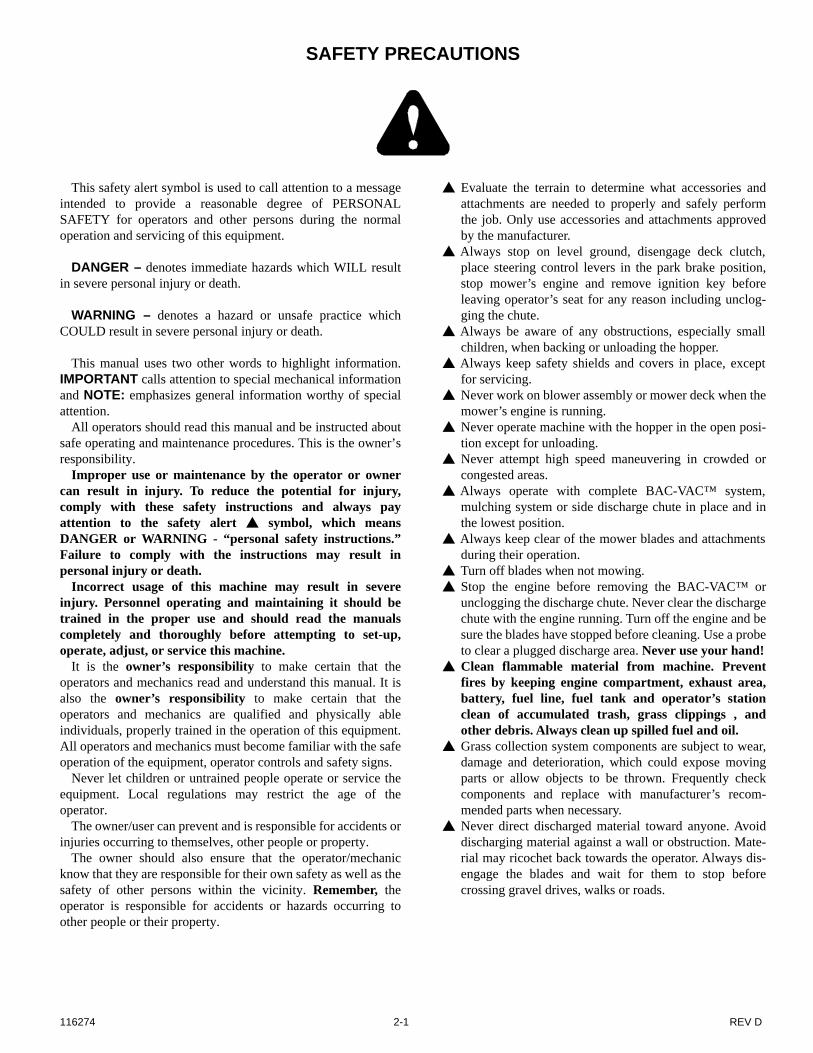
SAFETY PRECAUTIONS
This safety alert symbol is used to call attention to a messageintended to provide a reasonable degree of PERSONALSAFETY for operators and other persons during the normaloperation and servicing of this equipment.
DANGER – denotes immediate hazards which WILL resultin severe personal injury or death.
WARNING – denotes a hazard or unsafe practice whichCOULD result in severe personal injury or death.
This manual uses two other words to highlight information.IMPORTANT calls attention to special mechanical informationand NOTE: emphasizes general information worthy of specialattention.
All operators should read this manual and be instructed aboutsafe operating and maintenance procedures. This is the owner’sresponsibility.
Improper use or maintenance by the operator or ownercan result in injury. To reduce the potential for injury,comply with these safety instructions and always payattention to the safety alert symbol, which meansDANGER or WARNING - “personal safety instructions.”Failure to comply with the instructions may result inpersonal injury or death.
Incorrect usage of this machine may result in severeinjury. Personnel operating and maintaining it should betrained in the proper use and should read the manualscompletely and thoroughly before attempting to set-up,operate, adjust, or service this machine.
It is the owner’s responsibility to make certain that theoperators and mechanics read and understand this manual. It isalso the owner’s responsibility to make certain that theoperators and mechanics are qualified and physically ableindividuals, properly trained in the operation of this equipment.All operators and mechanics must become familiar with the safeoperation of the equipment, operator controls and safety signs.
Never let children or untrained people operate or service theequipment. Local regulations may restrict the age of theoperator.
The owner/user can prevent and is responsible for accidents orinjuries occurring to themselves, other people or property.
The owner should also ensure that the operator/mechanicknow that they are responsible for their own safety as well as thesafety of other persons within the vicinity. Remember, theoperator is responsible for accidents or hazards occurring toother people or their property.
Evaluate the terrain to determine what accessories andattachments are needed to properly and safely performthe job. Only use accessories and attachments approvedby the manufacturer.
Always stop on level ground, disengage deck clutch,place steering control levers in the park brake position,stop mower’s engine and remove ignition key beforeleaving operator’s seat for any reason including unclog-ging the chute.
Always be aware of any obstructions, especially smallchildren, when backing or unloading the hopper.
Always keep safety shields and covers in place, exceptfor servicing.
Never work on blower assembly or mower deck when themower’s engine is running.
Never operate machine with the hopper in the open posi-tion except for unloading.
Never attempt high speed maneuvering in crowded orcongested areas.
Always operate with complete BAC-VAC™ system,mulching system or side discharge chute in place and inthe lowest position.
Always keep clear of the mower blades and attachmentsduring their operation.
Turn off blades when not mowing. Stop the engine before removing the BAC-VAC™ or
unclogging the discharge chute. Never clear the dischargechute with the engine running. Turn off the engine and besure the blades have stopped before cleaning. Use a probeto clear a plugged discharge area. Never use your hand!
Clean flammable material from machine. Preventfires by keeping engine compartment, exhaust area,battery, fuel line, fuel tank and operator’s stationclean of accumulated trash, grass clippings , andother debris. Always clean up spilled fuel and oil.
Grass collection system components are subject to wear,damage and deterioration, which could expose movingparts or allow objects to be thrown. Frequently checkcomponents and replace with manufacturer’s recom-mended parts when necessary.
Never direct discharged material toward anyone. Avoiddischarging material against a wall or obstruction. Mate-rial may ricochet back towards the operator. Always dis-engage the blades and wait for them to stop beforecrossing gravel drives, walks or roads.

REV D 2-2 116274
WARNING: Thrown objects!Part Number 601624
Part Number 601837
s
• Never operate the mower deck with side deflector dam-aged, altered, removed or in raised position, except when the entire grass catcher attachment or mulching sys-tem is being used.
DANGER:Rotating blades, pulleys & belts
• Keep hands, feet and cloth-ing away.
• Keep shields or covers in place while machine is in operation.
Part Number 601625 Part Number 602757
• Read Operator’s Manual before attempting to operate this machine.
• Wear ear protection, eye pro-tection and safety shoes when operating this equip-ment.
DANGER:Rotating impeller
• Keep hands, feet and cloth-ing away.
• Keep shields or covers in place while machine is in operation.
• Stop engine, remove ignition key.
• Engage park brake.• Use a probe to clear debris
from blower assembly. Remove blower chute to clear debris from chute.
• Never engage mower deck unless the entire grass catcher attachment is prop-erly installed.
Part Number 603940 Part Number 603967
WARNINGCrushing body
• Stay clear of raised hopper door.
• Never get between the hop-per door and the hopper con-tainer.
• Do not reach or climb into the hopper.
• Never reach into the hopper door opening or hopper door linkage area.
WARNINGCrushing hand or foot
• Never reach into the crushing danger zone.
• Keep hands and feet away.
601625
602757
603940603967

116274 3-1 REV D
ASSEMBLY INSTRUCTION
These instructions apply to the assembly of the Hustler®
BAC-VAC™ to a Hustler® X-ONE or Super Z® 48”, 54”, 60”,66” or 72” mower.
It is intended that these units be installed by trained Hustler®
service personnel. If additional assistance is required, contactthe Hustler® Customer Service Department.
Directions given in these instructions, for example left andright, refer to direction while seated on the mower.
Before proceeding, read thru the following instructions tofamiliarize yourself, while at the same time identify andinventory kit parts supplied.
Unpack and inspect all parts. Notify carrier of any shippingdamages immediately.
Packing List – Hustler® X-ONE BAC-VAC™
Packing List - Hustler® Super Z BAC-VAC™
Deck Adapter Kits
The following adapter kits must be used when mounting theBAC-VAC™ to a particular deck.
Part No. Description Qty
550996 Blower assembly 1
N/A Weight assembly 1
603935 Wiring harness 1
N/A BAC-VAC™ assembly 1
N/A Control panel 1
036236 CS .312-18 X 1.00 HX G5 3
768523 FW .343 X .687 X .051/.080H 3
000331 WIRE TIE, SMALL/SHORT 7
025395 CB .375-16 X 1.00 G5 ZNY 2
086660 NT .375-16 HXZY NL 6
767954 FW .406 X .812 X .060 SAE 14
017616 CS .500-13 X 1.75 HX G5 6
767962 FW .531 X 1.063 X .090 SAE 20
008193 NT .500-13 HX G5 ZNYC 8
078386 FW .510 X 1.750 X .18 ZNYC 2
705954 CS .500-13 X 1.25 HX G5 ZN 6
053702 CE .620 X 3.0 X .15 X 2.84 2
704783 FW .625 X 1.50 X .105 ZN 4
023036 HP .148 X 2.690 ZN 2
603339 UB .375-16 X 2.00 X 3.00 SQ 2
603357 Flex tube 1
115787 LH X-ONE mount 1
115789 RH X-ONE mount 1
115790 Mount spacer 1
114661 Weight 10 lbs 4
016428 CS .375-16X2.500 HX G5 ZN 4
Part No. Description Qty
550996 Blower assembly 1
N/A Weight assembly 1
603935 Wiring harness 1
N/A BAC-VAC™ assembly 1
N/A Control panel 1
036236 CS .312-18 X 1.00 HX G5 3
768523 FW .343 X .687 X .051/.080H 3
000331 WIRE TIE, SMALL/SHORT 7
025395 CB .375-16 X 1.00 G5 ZNY 2
086660 NT .375-16 HXZY NL 6
767954 FW .406 X .812 X .060 SAE 6
017616 CS .500-13 X 1.75 HX G5 6
767962 FW .531 X 1.063 X .090 SAE 20
008193 NT .500-13 HX G5 ZNYC 8
078386 FW .510 X 1.750 X .18 ZNYC 2
705954 CS .500-13 X 1.25 HX G5 ZN 6
603340 UB .375-16 X 2.00 X 4.00 SQ 2
053702 CE .620 X 3.0 X .15 X 2.84 2
704783 FW .625 X 1.50 X .105 ZN 4
023036 HP .148 X 2.690 ZN 2
603356 Flex tube 1
115732 LH Super Z mount 1
115733 RH Super Z mount 1
115748 Mount spacer 1
Deck Size Adapter Kit P/N
48” (X-ONE) 113900
54” (X-ONE) 113901
X-ONE with 60” 113902
Super Z with 60” 113903
66” (Super Z) 113904
72” (Super Z) 113905

REV D 3-2 116274
Mower Deck Preparation
1. Park the mower on a flat surface. Always place the deckclutch switch in the disengaged position, place thesteering control levers in the park brake position and shutoff the ignition switch and remove the key from theswitch. Disconnect the negative battery cable.
2. 48”/54”/60” decks only – Remove the discharge chuteand torsion spring.66”/72” decks only – Remove the right side pulleycover, discharge chute, and torsion spring.NOTE: Retain these parts as they will be re-installedwhen the BAC-VAC™ is removed.
3. Release the deck drive belt tension. 48”/54”/60” decks only – Remove the existing spindlebolt and pulley from the center blade spindle.66”/72” decks only – Remove the existing spindle boltand pulley from the right side blade spindle. All decks – Replace the pulley with the double pulleyand place the new cup washer between the head of thenew bolt and the drive pulley. Thread the cup washer andbolt assembly into the spindle shaft. Torque bolt to 118ft.-lbs. Refer to Figure 3-1, Figure 3-2, Figure 3-3, Figure3-4 or Figure 3-5.
4. Attach the deck blowout baffle to the underneath side ofthe deck. Refer to Figure 3-1, Figure 3-2, Figure 3-3,Figure 3-4 or Figure 3-5.NOTE: This baffle replaces the existing right side adjust-able baffle provided with the deck.NOTE: The blowout baffle is most useful in dry, dustyconditions, particularly when picking up leaves. In otherconditions, the adjustable baffle, supplied with the deck,may provide better cut quality and dispersion than theblowout baffle.
5. Attach the blower baffle to the deck. Refer to Figure 3-1,Figure 3-2, Figure 3-3, Figure 3-4 or Figure 3-5.
6. Assemble the blower mount to blower assembly. Refer toFigure 3-1, Figure 3-2, Figure 3-3, Figure 3-4 or Figure3-5.
NOTE: The 48”/54” blower mount has two sets of holes.Use the rear set of holes when attaching to a 48” deck.Use the front set of holes when attaching to a 54” deck.Figure 3-1
7. Attach the blower assembly to the deck by inserting therod through the discharge chute bracket and blowermount and secure with nut. Refer to Figure 3-1, Figure 3-2, Figure 3-3, Figure 3-4 or Figure 3-5.
8. Place the deck drive belt around the lower pulley of thedouble pulley. Confirm that the belt is properly routedand seated on all pulleys and idlers. Re-tension the deckdrive belt per the tensioning instructions found in themower’s General Service Manual.
9. Install and route the blower belt around the blowerpulleys and the upper pulley on the double pulley. Thisbelt is self tensioning. Figure 3-6 or Figure 3-7
10. 48”/54” decks only – Remove the lower nut from theright front deck chain attaching bolt. Slide the blower beltcover mount bracket onto the bolt and re-install the nutand tighten. Figure 3-1
11. 60” decks only – Remove the front right side deck liftchain and attach the rigid link (115665) to the deck liftarm. Position the center drive bracket (115773) on the deck asshown and attach it and the rigid link (115665) to thedeck.NOTE: The rigid link (115665) must move freely in thetop slot and rotate freely in the bottom hole.
12. Attach the blower belt cover. Refer to Figure 3-1, Figure3-2, Figure 3-3, Figure 3-4 or Figure 3-5.
WARNING
Do not operate deck without discharge chute or completeBAC-VAC™ system in place.

116274 3-3 REV D
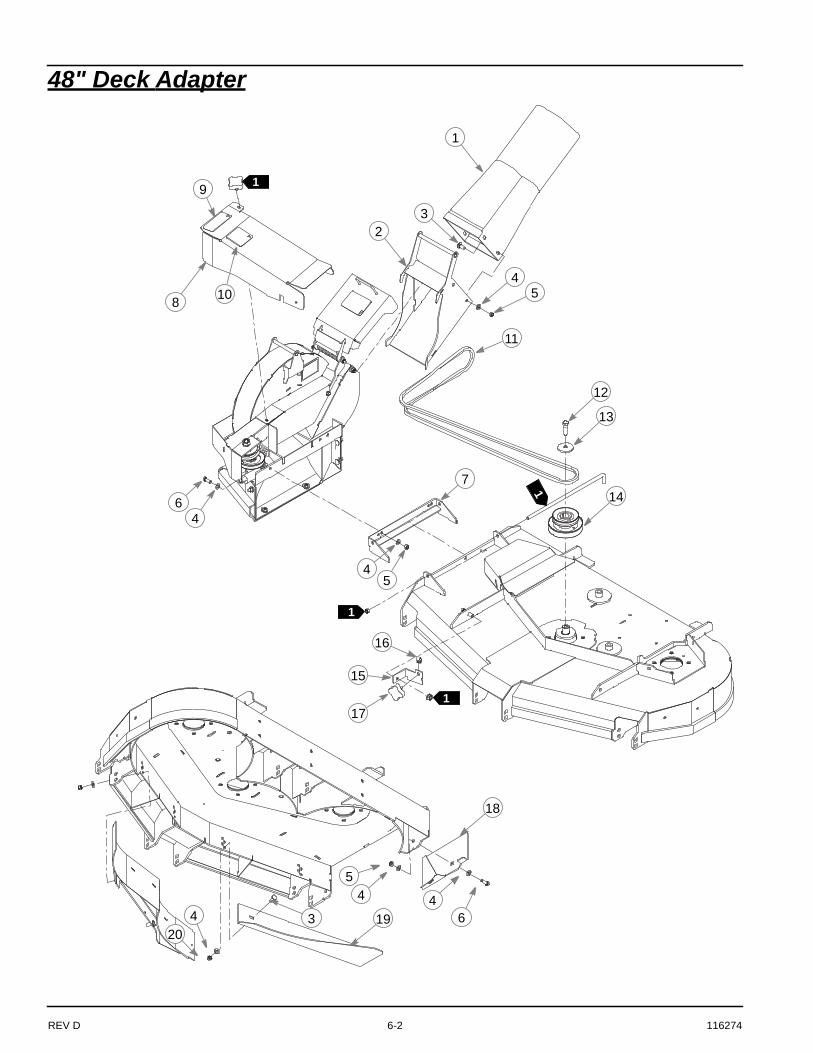
Figure 3-1
INDEXNO. PART NO. DESCRIPTION
1 603213 BLOWER OUTLET TUBE2 114066 OUTLET ADAPTER3 025395 CB .375-16 X 1.00 G5 ZNY4 767954 FW .406 X .812 X .060 SAE5 054502 NT .375-16 HX GRD 5 ZNY6 036244 CS .375-16 X 1.000 HX G57 114194 BLOWER MOUNT8 551034
551035BLOWER BELT COVER, 48"BLOWER BELT COVER, 54" (INCLUDES DECALS)
9 603318603319
BELT, A 97.0" EL, 48”BELT, A 103.0” EL, 54”
10 017616 CS .500-13 X 1.750 HX G5 11 752386 CW .515 X 2.25 X .204 BLK12 603309
603310DOUBLE PULLEY, 48" DOUBLE PULLEY, 54”
13 114388114389
BELT COVER BRACKET, 48" BELT COVER BRACKET, 54”
14 601069 CN .312-18 X .200 MAX THK15 792002 KNOB 5/16-18 X 3/4"16 114068
114071BLOWER BAFFLE, 48"BLOWER BAFFLE, 54”
17 114359114360
RH BLOWOUT BAFFLE, 48"RH BLOWOUT BAFFLE, 54”
18 086660 NT .375-16 HXZY NL19 601624 DECAL20 601837 DECAL
2
1
3
4
4
4
4
4 4
5
5
5
6
6
7
910
11
12
13
14
15
17
318
8
16
Existing hardware
Existing hardware
Existing hardware
Blower assembly
113900 (48”) & 113901 (54”) Adapter Assembly
Existing hardware
48” mount hole
54” mount hole
Discharge cover
Install in lower set of holes
1
NOTES:1. Bracket shown for 48” deck. 54” deck
bracket formed opposite.
20
19

REV D 3-4 116274
Figure 3-2
INDEX NO. PART NO. DESCRIPTION
1 551305 CENTER DRIVE COVER (INCLUDES DECALS)
2 603806 110.5" EL A-SEC BELT3 114361 RS BLOWOUT BAFFLE4 113127 BLOWER BAFFLE5 113118 BLOWER MOUNT6 792002 KNOB 5/16-18 X 3/4"7 115665 RIGID LINK8 115773 CENTER DRIVE BRACKET9 603311 60" DOUBLE DRIVE PULLEY10 752386 CW .515 X 2.25 X .204 BLK11 017616 CS .500-13 X 1.750 HX G5 12 036244 CS .375-16 X 1.000 HX G513 025395 CB .375-16 X 1.00 G5 ZNY14 767954 FW .406 X .812 X .060 SAE15 054502 NT .375-16 HX GRD 5 ZNY16 086660 NT .375-16 HXZY NL17 601069 CN .312-18 X .200 MAX THK18 601624 DECAL19 601837 DECAL
1
2
3
5
4
7
8
9
10
15
11
13
6
12
14
Existing hardware
Blower assembly
Existing hardware
14
14
16
12
Existing hardware
Outlet tube and adapter assembly
7
Existing hardware
Existing rod
Existing hardware
Existing hardware
14
14
15
Install in lower set of holes
17
Discharge cover
Existing hardware
113902 (60” X-ONE) Adapter Assembly
18
19

116274 3-5 REV D
Figure 3-3
1
2
3
4
5
7
8
9
10
16
13
15
6
INDEX NO. PART NO. DESCRIPTION
1 551305 CENTER DRIVE COVER (INCLUDES DECALS)
2 603806 110.5" EL A-SEC BELT3 114361 RS BLOWOUT BAFFLE4 113118 BLOWER MOUNT5 113127 BLOWER BAFFLE6 792002 KNOB 5/16-18 X 3/4"7 115665 RIGID LINK8 115773 CENTER DRIVE BRACKET9 602914 DOUBLE PULLEY10 752386 CW .515 X 2.25 X .204 BLK11 045765 FW 1.030 X 1.500 X .134 ZN 12 767954 FW .406 X .812 X .060 SAE13 008573 CS .500-13 X 2.500 HX G514 036244 CS .375-16 X 1.000 HX G515 025395 CB .375-16 X 1.00 G5 ZNY16 054502 NT .375-16 HX GRD 5 ZNY17 086660 NT .375-16 HXZY NL18 601069 CN .312-18 X .200 MAX THK19 601624 DECAL20 601837 DECAL
14
113903 (60” Super Z) Adapter Assembly
12
Existing hardware
Blower assembly
Existing hardware
Existing hardware
Existing hardware
18
Discharge cover
Install in lower set of holes
12
12
12
12
17 14
Existing hardware
Existing hardware
7
16
Existing hardware
Outlet tube and adapter assembly
11
Existing rod
19
20

REV D 3-6 116274
Figure 3-4
21
3
4
13
44
44 4
5
5
5
6
6
7
9 1011
12
14
15
316
8
INDEXNO. PART NO. DESCRIPTION
1 603324 BLOWER OUTLET TUBE2 114066 OUTLET ADAPTER3 025395 CB .375-16 X 1.00 G5 ZNY4 767954 FW .406 X .812 X .060 SAE5 054502 NT .375-16 HX GRD 5 ZNY6 036244 CS .375-16 X 1.000 HX G57 113118 BLOWER MOUNT8 551037 BLOWER BELT COVER
(INCLUDES DECALS)9 602997 BELT, A 86.0" EL
10 017616 CS .500-13 X 1.750 HX G5 11 752386 CW .515 X 2.25 X .204 BLK12 603312 DOUBLE PULLEY 13 114349 DOUBLE PULLEY COVER14 114074 BLOWER BAFFLE15 114362 RH BLOWOUT BAFFLE16 086660 NT .375-16 HXZY NL17 601624 DECAL18 601837 DECAL
113904 (66”) Adapter Assembly
Existing hardware
Blower assembly
Existing hardware
Existing hardware
Discharge cover
Install in lower set of holes
18
17

116274 3-7 REV D
Figure 3-5
2
1
3
4
4
4
4
44
5
5
5
6
6
7
91011
12
13
14
16
8
INDEXNO. PART NO. DESCRIPTION
1 603324 BLOWER OUTLET TUBE2 114066 OUTLET ADAPTER3 025395 CB .375-16 X 1.00 G5 ZNY4 767954 FW .406 X .812 X .060 SAE5 054502 NT .375-16 HX GRD 5 ZNY6 036244 CS .375-16 X 1.000 HX G57 113118 BLOWER MOUNT8 551038 BLOWER BELT COVER
(INCLUDES DECALS)9 602998 BELT, A 89.0" EL
10 017616 CS .500-13 X 1.750 HX G5 11 752386 CW .515 X 2.25 X .204 BLK12 603313 DOUBLE PULLEY13 114350 DOUBLE PULLEY COVER14 114077 BLOWER BAFFLE15 114363 RH BLOWOUT BAFFLE16 086660 NT .375-16 HXZY NL17 601624 DECAL18 601837 DECAL
15
113905 (72”) Adapter Assembly
3
Existing hardware
Blower assembly
Existing hardware
Existing hardware
Discharge cover
Install in lower set of holes
18
17

REV D 3-8 116274
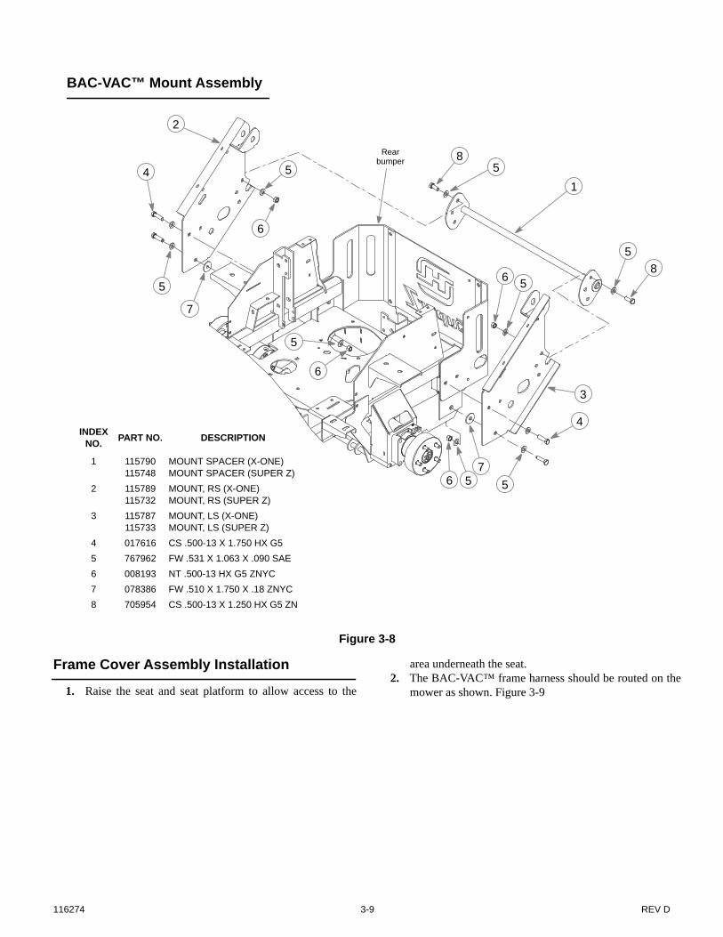
Mower Preparation
1. Remove the two cap screws that attach the left side of the
rear bumper to the mower frame. Figure 3-82. Attach the left side mount to the rear bumper and the
mower frame using the hardware shown. Figure 3-83. Repeat steps 1 & 2 for the opposite side. Figure 3-84. Attach the mount spacer to the left and right mounts as
shown. Figure 3-85. Tighten all hardware.
Figure 3-6
WARNING
Allow engine and muffler to cool before assembling theunit to the mower.
48”/54”/60” Blower Belt Routing
Blower belt
Figure 3-7
66”/72” Blower Belt Routing
Blower belt
116274 3-9 REV D
Frame Cover Assembly Installation
1. Raise the seat and seat platform to allow access to the
area underneath the seat.2. The BAC-VAC™ frame harness should be routed on the
mower as shown. Figure 3-9
Figure 3-8
INDEXNO. PART NO. DESCRIPTION
1 115790115748
MOUNT SPACER (X-ONE)MOUNT SPACER (SUPER Z)
2 115789115732
MOUNT, RS (X-ONE)MOUNT, RS (SUPER Z)
3 115787115733
MOUNT, LS (X-ONE)MOUNT, LS (SUPER Z)
4 017616 CS .500-13 X 1.750 HX G5 5 767962 FW .531 X 1.063 X .090 SAE6 008193 NT .500-13 HX G5 ZNYC7 078386 FW .510 X 1.750 X .18 ZNYC8 705954 CS .500-13 X 1.250 HX G5 ZN
6
6
2
7
65
3
84
1
BAC-VAC™ Mount Assembly
Rear bumper
8
75
5
5
4
5
5
5
56

REV D 3-10 116274
3. Remove the existing left side frame cover and right sideframe cover from the mower. Figure 3-10 & Figure 3-11
4. Unbolt the hose clamp from the mower frame that thewiring harness to the control panel goes through. Do notremove the wiring harness from the clamp. Figure 3-12
5. Route the BAC-VAC™ frame harness pigtail that has thetwo connector bodies through the hose clamp andretighten clamp hardware. Figure 3-12
6. Remove the mower’s control panel.7. Locate the auxiliary connector body underneath the
control panel and remove the cap. Figure 3-13 8. Plug the BAC-VAC™ frame harness connector into the
auxiliary plug. Figure 3-14 9. Secure the BAC-VAC™ frame harness to the main
mower harness with a wire tie. Figure 3-15 10. Re-attach the mower control panel. Make sure that the
wiring harnesses are routed through the slot in the bottomof the control panel correctly.
11. Re-attach the right frame cover to the mower frame.
12. Route the BAC-VAC™ frame harness as shown (Figure3-9) and connect the appropriate wires to the batteryterminals. Secure the BAC-VAC™ frame harness to themower using the wire ties as shown. Make sure that noneof the harness will come in contact with any movingparts. Figure 3-16 & Figure 3-17
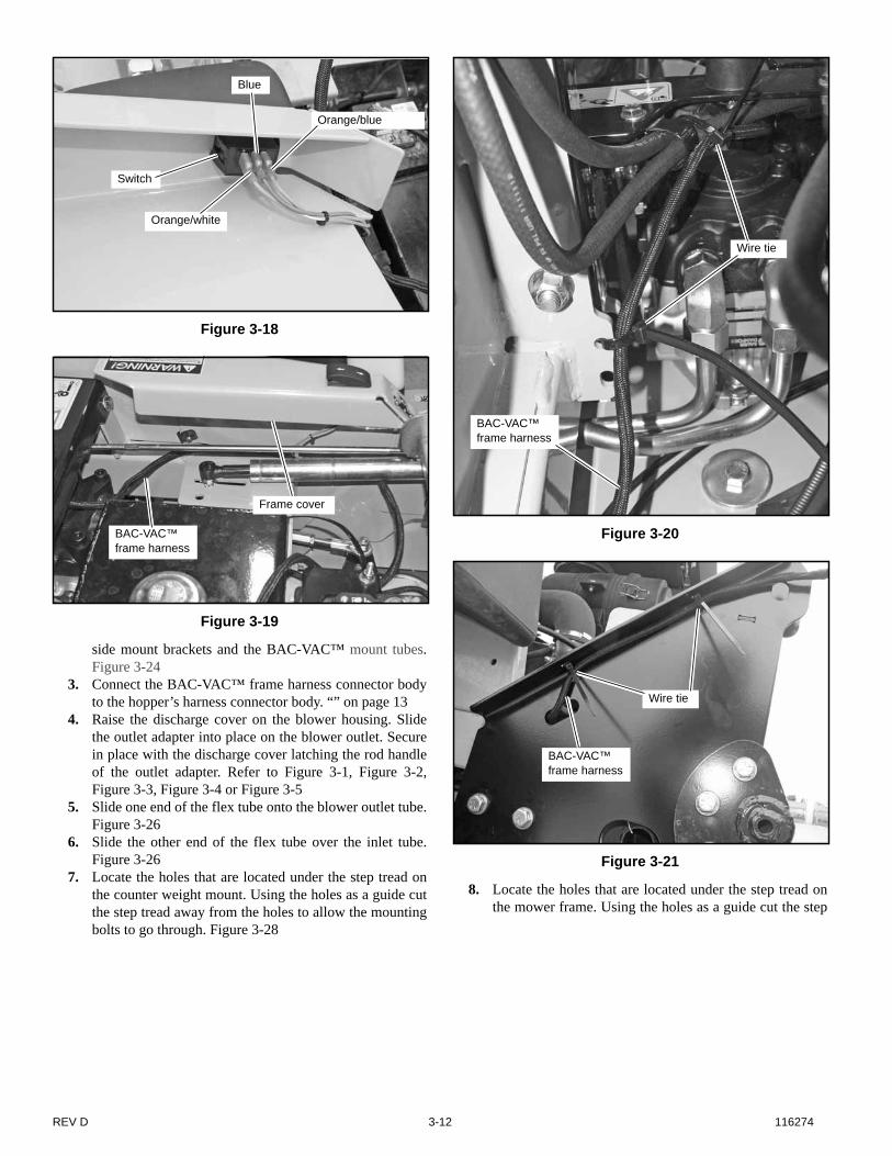
13. Attach the three wires on the wiring harness to the BAC-VAC™ switch. Figure 3-18
14. Attach the left frame cover assembly to the mower frame.Figure 3-19
15. Route the BAC-VAC™ frame harness along the left sideof the mower frame as shown. Secure the harness to themower using the wire ties as shown. Figure 3-20 &Figure 3-21
Figure 3-9
Figure 3-10
Frame wire harness
Frame wire harness
Right side frame cover
Figure 3-11
Figure 3-12
Existing left side frame cover
Remove this hardware
Hose clamp
Wire harness

116274 3-11 REV D
Final Connection
1. Park the mower on a flat surface. Always place the deckclutch switch in the disengaged position, place the
steering control levers in the park brake position and shutoff the ignition switch and remove the key from theswitch. Disconnect the negative battery cable.
2. Roll the BAC-VAC™ to the mower and slide the lowerhooks over the rod on the mount tube. Figure 3-25 NOTE: It is recommended that two people attach thehopper to the mower mounts. One person to roll the hop-per into position, slide the lower hooks onto the mountspacer and pivot it into position. The second person toinsert the clevis pins, flat washers, and hair pins thru the
Figure 3-13
Figure 3-14
Figure 3-15
Auxiliary connector body
Cap
Auxiliary connector body
BAC-VAC™ frame harness connector
BAC-VAC™ frame harness
Main mower harness
Wire tie
Figure 3-16
Figure 3-17
BAC-VAC™ frame harness
Wire ties
+ Battery terminal – Battery
terminalRed wire
Black wire
Wire ties
REV D 3-12 116274
side mount brackets and the BAC-VAC™ mount tubes.Figure 3-24
3. Connect the BAC-VAC™ frame harness connector bodyto the hopper’s harness connector body. “” on page 13
4. Raise the discharge cover on the blower housing. Slidethe outlet adapter into place on the blower outlet. Securein place with the discharge cover latching the rod handleof the outlet adapter. Refer to Figure 3-1, Figure 3-2,Figure 3-3, Figure 3-4 or Figure 3-5
5. Slide one end of the flex tube onto the blower outlet tube.Figure 3-26
6. Slide the other end of the flex tube over the inlet tube.Figure 3-26
7. Locate the holes that are located under the step tread onthe counter weight mount. Using the holes as a guide cutthe step tread away from the holes to allow the mountingbolts to go through. Figure 3-28
8. Locate the holes that are located under the step tread onthe mower frame. Using the holes as a guide cut the step
Figure 3-18
Figure 3-19
Orange/white
Orange/blue
Blue
Switch
Frame cover
BAC-VAC™ frame harness
Figure 3-20
Figure 3-21
Wire tie
BAC-VAC™ frame harness
Wire tie
BAC-VAC™ frame harness
116274 3-13 REV D
tread away from the holes to allow the mounting bolts forthe counter weight mount to go through. Figure 3-28
9. Attach the four auxiliary weights to the weight mount asshown. Figure 3-27
10. Attach the counter weight mount to the front of themower. Figure 3-28NOTE: When attaching the counter weight mount to aframe for a 48” deck, the inside set of holes is used forthe u-bolts to attach to the front wheel arms.NOTE: The Super Z weight mount has only one set ofholes.
11. Slide the weights vertically onto the mount and lock inplace using the weight lock plate and tighten knobs.Figure 3-28
12. Reconnect the negative battery cable. 13. Increase the mower’s drive tire’s pressure to 16 psi (110
KPa). The drive tires will need to have to the air pressureincreased to support the additional weight of the BAC-VAC™ system and when grass clippings are in thehopper. NOTE: When the BAC-VAC™ system is removed theair pressure in the tires should be decreased to the normaloperating range of 8 - 12 psi (55 - 83 KPa). .
Figure 3-22
CS .312 x 1.00FW .343 x .687
Frame cover
Figure 3-23
Hooper harness connector body
BAC-VAC™ frame harness connector body

REV D 3-14 116274
Figure 3-24
INDEXNO. PART NO. DESCRIPTION
1 053702 CE .620 X 3.0 X .15 X 2.842 704783 FW .625 X 1.500 X .105 ZN3 023036 HP .148 X 2.690 ZN
2
1
BAC-VAC™ Assembly
2
32
2
1
Hopper assembly
Figure 3-25
Figure 3-26
Mount tube Hooks
Blower outlet tube
Inlet tube
Flex tube
Figure 3-27
INDEXNO. PART NO. DESCRIPTION
1 114327 WEIGHT MOUNT (X-ONE)2 114661 WEIGHT 10 LBS3 016428 CS .375-16X2.500 HX G5 ZN4 767954 FW .406 X .812 X .060 SAE5 054502 NT .375-16 HX G5 ZN
3
2
1
5
4
4

116274 3-15 REV D
Figure 3-28
2
3
6
8
7
1
9
7
8
4
5
8
78
948" DECK
54"/60" DECK
INDEXNO. PART NO. DESCRIPTION
1 114323 WEIGHT LOCK PLATE2 792002 KNOB 5/16-18 X 3/4"3 114327
114317WEIGHT MOUNT (X-ONE)WEIGHT MOUNT (SUPER Z)
4 781880 BUMPER5 025395 CB .375-16 X 1.00 G5 ZNY6 603207 WEIGHT7 086660 NT .375-16 HXZY NL8 767954 FW .406 X .812 X .060 SAE9 603339
603340UB .375-16 X 2.00 X 3.00 SQ (X-ONE)UB .375-16 X 2.00 X 4.00 SQ (SUPER Z)
Weight Assembly
Locate holes and cut the step tread here
Locate holes and cut the step tread here

REV D 3-16 116274
116274 4-1 REV D
OPERATION
Vacuum Pickup and Collection
Follow normal mower start-up and operating procedures asoutlined in the mower operator’s manual. The blower willoperate when the mower deck clutch switch is engaged. To stopthe blower, return the deck clutch switch to the disengagedposition.
Proceed to mow in the normal manner and occasionallyglance at the flex tube. When the hopper is full the speed ofdebris through the tube will decrease. When the hopper is filled,move the deck clutch switch to the disengaged position anddrive the machine to the unloading area.
It is best that the hopper be unloaded before the dischargechute and flex tube areas become clogged. If clogging occurs, itwill be necessary to clear the blower chute and flex tube areas ofall material before starting to mow again.
Unloading the BAC-VAC™
The BAC-VAC™ is designed to dump it’s load in adesignated area on the ground while the mower is stationary.
To dump the BAC-VAC™, place the steering control levers inthe park brake position to prevent accidental mower movementor engine cutting in and out.
NOTE: The mower’s ignition switch must be in the “ON”position to open or close the hopper door.
Hold the BAC-VAC™ operating switch in the “open”position until the hopper door comes to a stop. Keep the hopperdoor open until all of the clippings have been discharged fromthe hopper. Then close the hopper door by holding the operatingswitch in the “closed” position until the hopper door has closedall the way. The deck clutch switch may then be engaged tocontinue mowing.
Converting To Side Discharge Mode
1. Park the mower on a flat surface. Turn engine off, placethe steering control levers in the park brake position andremove the ignition key. Be sure blades have stoppedbefore dismounting from the mower.
2. Remove the flex tube from the BAC-VAC™ inlet tubeand blower outlet tube. Figure 4-1
3. Remove the blower outlet tube from the blowerassembly. Figure 4-1
4. Remove the blower belt cover from the deck. Figure 4-15. Release the tension from the blower drive belt and
remove it. Figure 4-2 & Figure 4-3NOTE: It is not necessary to remove the double pulleyon the deck spindle.
6. Remove the pin that connects the blower to the dischargechute bracket tabs and remove the blower housing.Figure 4-2 & Figure 4-3
7. Assemble the torsion spring, original discharge chute andpin to the bracket tabs. Make sure the torsion spring is
WARNING
Make certain the engine is turned off, the steering controllevers are in the park brake position and the ignition keyis removed from the ignition switch and be sure bladeshave stopped before clearing the blower chute and flextube areas.
WARNING
Never place hands or feet into the discharge area. Theimpeller is relatively close to the housing and will causesevere injury. Use a probe to clean debris from blowerhousing discharge area. The discharge cover must remainclosed whenever the blower chute is removed.
WARNING
Never engage mower deck unless BAC-VAC™ flex tubeis in place on the BAC-VAC™ inlet tube and insertedonto blower chute outlet tube.
WARNING
Prevent objects being thrown and the accumulation ofgrass clippings and other debris in engine compart-ment by NEVER operating mower deck unless:
• BAC-VAC™ is in the catching position.• Flex tube is in place on the blower chute and on
the BAC-VAC™ inlet tube.• Only operate when hopper door is fully closed.
WARNING
Make certain the deck clutch switch is in the disengagedposition before unloading.
WARNING
Never approach the BAC-VAC™ hopper while themower’s ignition switch is in the “ON” position.
WARNING
Never work on the blower assembly or the mower deckwhen the mower engine is running.

REV D 4-2 116274
assembled as shown so that it applies pressure to thedischarge chute and keeps it in the down position. Figure4-4
8. Remove the blower baffle and replace it with the rightside adjustable baffle that was provided with the deck.Figure 3-1, Figure 3-2, Figure 3-3, Figure 3-4 & Figure3-5
9. 66” & 72” decks only – Assemble the tall pulley cover(included with the adapter kit) to the deck. Figure 4-4
10. Remove the BAC-VAC™ from the rear of the machine.(See Removing the BAC-VAC™ section below.NOTE: It is not necessary to remove the BAC-VAC™frame that is attached to the rear of the mower.
Removing The BAC-VAC™
Use the following procedure when removing the BAC-VAC™ from the mower.
1. Park the mower on a flat surface. Turn engine off, placethe steering control levers in the park brake position andremove the ignition key. Be sure blades have stoppedbefore dismounting from the mower.
2. Disconnect the BAC-VAC™ frame harness from thehopper’s wire harness.
3. Remove the flex tube from the BAC-VAC™ inlet tube.Figure 4-1
4. Unpin the BAC-VAC™ assembly from the side mount
brackets and pivot it until the lower hooks clear themount spacer. Figure 4-5 NOTE: It is recommended that two people remove thehopper from the mower mounts. The first person to holdthe hopper in place while the second person removes theclevis pins, flat washers, and hair pins from the sidemount brackets and the BAC-VAC™ mount tubes. The
WARNING
Always operate with complete BAC-VAC™, mulchingsystem or side discharge chute in place and in the lowestposition.
WARNING
Never operate the mower deck with side deflector dam-aged, altered, removed or in raised position, except whenthe entire BAC-VAC™ attachment or mulching system isbeing used.
Figure 4-1
Inlet tube
Flex tube
Blower outlet tube
Blower belt cover
Figure 4-2
Figure 4-3
Figure 4-4
Blower belt
Double pulley
Pin
48”/54”/60” Blower Belt Routing
66”/72”” Blower Belt Routing
Blower belt
Double pulley
Pin
Tall pulley cover
Discharge chute
Pin
Torsion spring

116274 4-3 REV D
first person will then pivot the hopper away from the sidemount brackets, slide the lower hooks off the mount tubeand roll it away from the mower.
5. Re-insert the latching pins into frame mount for storage.Secure in place with the hair pins. Tuck the BAC-VAC™
frame harness under the left side latching pin forprotection. Figure 4-6
6. Roll the BAC-VAC™ away from the mower.
Figure 4-5
BAC-VAC™
Hook
Unpin here
Unpin here
Figure 4-6
Latching pin
BAC-VAC™ frame harness

REV D 4-4 116274
116274 5-1 REV D
MAINTENANCE & STORAGE
Blower Housing and Flex Tube Maintenance
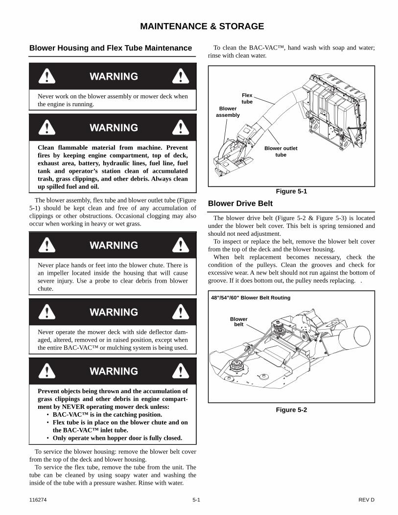
The blower assembly, flex tube and blower outlet tube (Figure5-1) should be kept clean and free of any accumulation ofclippings or other obstructions. Occasional clogging may alsooccur when working in heavy or wet grass.
To service the blower housing: remove the blower belt coverfrom the top of the deck and blower housing.
To service the flex tube, remove the tube from the unit. Thetube can be cleaned by using soapy water and washing theinside of the tube with a pressure washer. Rinse with water.
To clean the BAC-VAC™, hand wash with soap and water;rinse with clean water.
Blower Drive Belt
The blower drive belt (Figure 5-2 & Figure 5-3) is locatedunder the blower belt cover. This belt is spring tensioned andshould not need adjustment.
To inspect or replace the belt, remove the blower belt coverfrom the top of the deck and the blower housing.
When belt replacement becomes necessary, check thecondition of the pulleys. Clean the grooves and check forexcessive wear. A new belt should not run against the bottom ofgroove. If it does bottom out, the pulley needs replacing. .
WARNING
Never work on the blower assembly or mower deck whenthe engine is running.
WARNING
Clean flammable material from machine. Preventfires by keeping engine compartment, top of deck,exhaust area, battery, hydraulic lines, fuel line, fueltank and operator’s station clean of accumulatedtrash, grass clippings, and other debris. Always cleanup spilled fuel and oil.
WARNING
Never place hands or feet into the blower chute. There isan impeller located inside the housing that will causesevere injury. Use a probe to clear debris from blowerchute.
WARNING
Never operate the mower deck with side deflector dam-aged, altered, removed or in raised position, except whenthe entire BAC-VAC™ or mulching system is being used.
WARNING
Prevent objects being thrown and the accumulation ofgrass clippings and other debris in engine compart-ment by NEVER operating mower deck unless:
• BAC-VAC™ is in the catching position.• Flex tube is in place on the blower chute and on
the BAC-VAC™ inlet tube.• Only operate when hopper door is fully closed.
Figure 5-1
Figure 5-2
Flex tube
Blower outlet tube
Blower assembly
Blower belt
48”/54”/60” Blower Belt Routing

REV D 5-2 116274
BAC-VAC™ Hopper
Use a pressure washer to clean the inside and outside of thehopper.
NOTE: Do not spray the linear actuator with the pressurewasher.
It will be necessary to lubricate the three grease pointsshown in Figure 5-4 every 40 hours or after every powerwashing. NOTE: It will be necessary to remove the actuatorcover to access the center grease zerk.
BAC-VAC™ Hopper Switch Adjustment
Occasionally it may be necessary to adjust the sensor switcheson the hopper door. These switches, when adjusted properly,make sure that the hopper door is closing and sealing properly.
1. Ensure that the BAC-VAC™ is fully mounted and thatthe hopper wire harness and the mower frame harness areconnected.
2. With the hopper door closed, press the control switch onthe mower so that the door opens.Allow the door to open fully. If the actuator makes a
ratcheting sound before the door stops moving then theangled sensor switch needs to be adjusted so that more ofthe plunger is exposed out of the switch’s control body.The plunger depth is adjusted by loosening the twoscrews, repositioning the switch body, and thentightening the screws.Repeat the test and adjustment until the door stops itsopening motion before the actuator ratchets.
3. With the door open, press the switch on the mower so thatthe door closes.The sensor switch should have a .5 second delay. Allowthe door to close. The door should close and compress thedoor/shell joint and the actuator should ratchet and afterapproximately .5 seconds the ratcheting should stop.If the actuator does not ratchet then the horizontal sensorswitch needs to be adjusted so that less of the plunger isexposed out of the switch’s control body. If the actuator does not stop ratcheting then the horizontalsensor switch needs to be adjusted so that more of theplunger is exposed out of the switch’s control body.
4. After the switches are correctly set, open the door andadjust the two turnbuckles by tightening them by twocomplete revolutions. tighten the jam nuts on theturnbuckles. Figure 5-6
Figure 5-3
Figure 5-4
Blower belt
66”/72”” Blower Belt Routing
Grease zerks
Figure 5-5
Screws
Angled sensor switch plunger
Horizontal sensor switch
plunger
Screws
Control box

116274 5-3 REV D
Blower Impeller
The blower impeller shaft bearings do not require lubrication.
Storage
When your mower is to set idle for a period of time, scrapeand power wash to remove the grass material from inside theBAC-VAC™.
Check for loose or missing hardware, tighten or replace. Alsocheck for badly worn or damaged parts, consider replacing themat this time. Touch up chipped paint areas, your dealer hasaerosol spray paint available
Figure 5-6
WARNING
Normal wear can cause the impeller and edges of theblower to become sharp. Wear gloves and use cautionwhen servicing the blower.
Lock nut
Turnbuckle
Lock nut

REV D 5-4 116274

116274 6-1 REV D
Parts Manual
Frame . . . . . . . . . . . . . . . . . . . . . . . . . . . . . . . . . . . . . . . . . . . . . . . . 6-2
Shell. . . . . . . . . . . . . . . . . . . . . . . . . . . . . . . . . . . . . . . . . . . . . . . . . . 6-4
Lid . . . . . . . . . . . . . . . . . . . . . . . . . . . . . . . . . . . . . . . . . . . . . . . . . . . 6-6
Linkage . . . . . . . . . . . . . . . . . . . . . . . . . . . . . . . . . . . . . . . . . . . . . . . 6-8
Frame Adapter. . . . . . . . . . . . . . . . . . . . . . . . . . . . . . . . . . . . . . . . . 6-10
Shell Electric . . . . . . . . . . . . . . . . . . . . . . . . . . . . . . . . . . . . . . . . . . 6-12
Wire Harness . . . . . . . . . . . . . . . . . . . . . . . . . . . . . . . . . . . . . . . . . . 6-14
Blower . . . . . . . . . . . . . . . . . . . . . . . . . . . . . . . . . . . . . . . . . . . . . . . 6-16
REV D 6-2 116274
48" Deck Adapter
1
2
1
3
4
4
4
44 4
5
5
5
6
6
7
9
10
11
12
13
14
15
16
17
19320
1
1
8
18
1
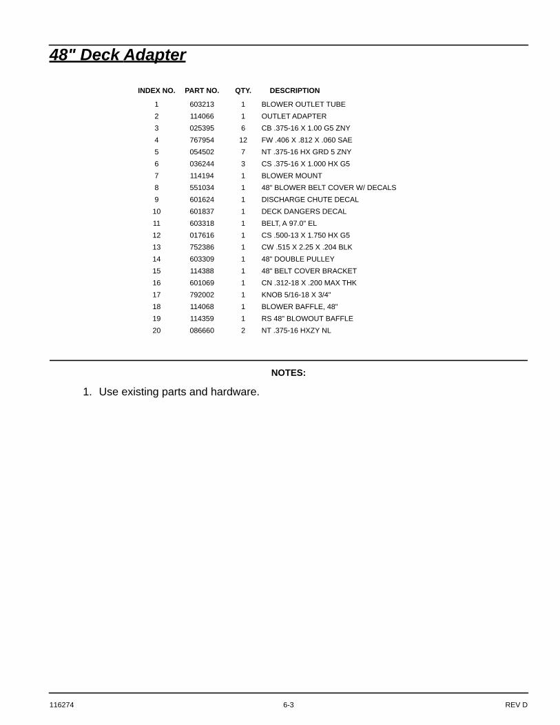
116274 6-3 REV D
48" Deck Adapter
NOTES:
1. Use existing parts and hardware.
INDEX NO. PART NO. QTY. DESCRIPTION
1 603213 1 BLOWER OUTLET TUBE2 114066 1 OUTLET ADAPTER3 025395 6 CB .375-16 X 1.00 G5 ZNY4 767954 12 FW .406 X .812 X .060 SAE5 054502 7 NT .375-16 HX GRD 5 ZNY6 036244 3 CS .375-16 X 1.000 HX G57 114194 1 BLOWER MOUNT8 551034 1 48" BLOWER BELT COVER W/ DECALS9 601624 1 DISCHARGE CHUTE DECAL
10 601837 1 DECK DANGERS DECAL11 603318 1 BELT, A 97.0" EL12 017616 1 CS .500-13 X 1.750 HX G5 13 752386 1 CW .515 X 2.25 X .204 BLK14 603309 1 48" DOUBLE PULLEY15 114388 1 48" BELT COVER BRACKET16 601069 1 CN .312-18 X .200 MAX THK17 792002 1 KNOB 5/16-18 X 3/4"18 114068 1 BLOWER BAFFLE, 48"19 114359 1 RS 48" BLOWOUT BAFFLE20 086660 2 NT .375-16 HXZY NL
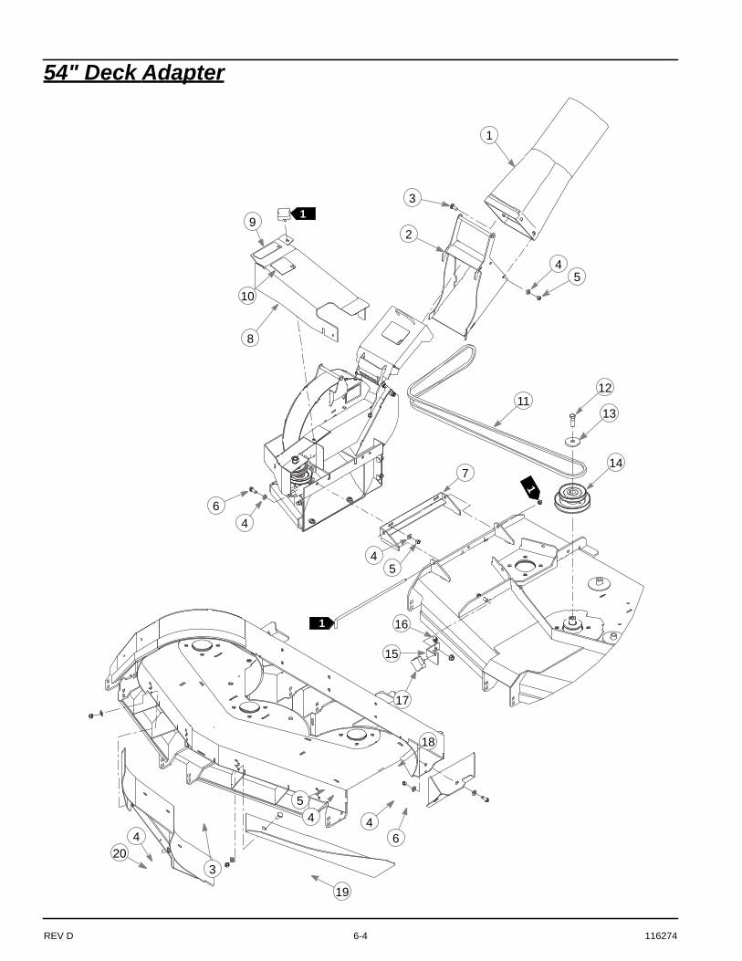
REV D 6-4 116274
54" Deck Adapter
1
2
1
3
4
4
4
44 4
5
5
5
6
6
7
9
10
1112
13
14
15
16
17
19
320
11
8
18

116274 6-5 REV D
54" Deck Adapter
NOTES:
1. Use existing parts and hardware.
INDEX NO. PART NO. QTY. DESCRIPTION
1 603213 1 BLOWER OUTLET TUBE2 114066 1 OUTLET ADAPTER3 025395 6 CB .375-16 X 1.00 G5 ZNY4 767954 12 FW .406 X .812 X .060 SAE5 054502 7 NT .375-16 HX GRD 5 ZNY6 036244 3 CS .375-16 X 1.000 HX G57 114194 1 BLOWER MOUNT8 551035 1 54" BLOWER BELT COVER W/ DECALS9 601624 1 DISCHARGE CHUTE DECAL
10 601837 1 DECK DANGERS DECAL11 603319 1 BELT, A 103.0" EL12 017616 1 CS .500-13 X 1.750 HX G5 13 752386 1 CW .515 X 2.25 X .204 BLK14 603310 1 54" DOUBLE DRIVE15 114389 1 54" BELT COVER BRACKET16 601069 1 CN .312-18 X .200 MAX THK17 792002 1 KNOB 5/16-18 X 3/4"18 114071 1 54" BLOWER BAFFLE19 114360 1 RS 54" BLOWER BAFFLE20 086660 2 NT .375-16 HXZY NL

REV D 6-6 116274
60" X-ONE Deck Adapter
1
3
1
2
4
7
15
14
5
9
1
8
1110
12
4
4
13
5
1716
20
19
2 4
515
21 4
1
6
1
1
18
1
1
116274 6-7 REV D
60" X-ONE Deck Adapter
NOTES:
1. Use existing parts and hardware.
INDEX NO. PART NO. QTY. DESCRIPTION
1 603213 1 BLOWER OUTLET TUBE2 025395 7 CB .375-16 X 1.00 G5 ZNY3 114066 1 OUTLET ADAPTER4 767954 13 FW .406 X .812 X .060 SAE5 054502 7 NT .375-16 HX GRD 5 ZNY6 551305 1 CENTER DRIVE COVER (WITH DECALS)7 601624 1 DISCHARGE CHUTE DECAL8 601837 1 DECK DANGERS DECAL9 792002 1 KNOB 5/16-18 X 3/4"
10 603806 1 110.5" EL A-SEC BELT11 017616 1 CS .500-13 X 1.750 HX G5 12 752386 1 CW .515 X 2.25 X .204 BLK13 603311 1 60" DOUBLE DRIVE14 113118 1 BLOWER MOUNT15 036244 3 CS .375-16 X 1.000 HX G516 601069 1 CN .312-18 X .200 MAX THK17 115773 1 CENTER DRIVE BRACKET18 115665 1 RIGID LINK19 113127 1 BLOWER BAFFLE20 114361 1 RS BLOWOUT BAFFLE21 086660 3 NT .375-16 HXZY NL
REV D 6-8 116274
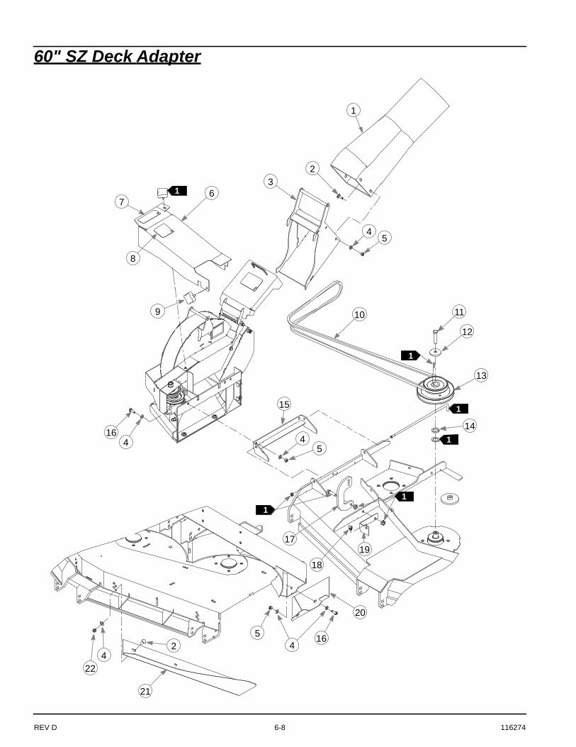
60" SZ Deck Adapter
3
1
2
8
4
1614
6
10
7
5
11
12
13
4 4
15
5
18
17
21
19
2 45 16
224
1
1
1
20
11
9
1

116274 6-9 REV D
60" SZ Deck Adapter
NOTES:
1. Use existing parts and hardware.
INDEX NO. PART NO. QTY. DESCRIPTION
1 603324 1 BLOWER OUTLET TUBE2 025395 7 CB .375-16 X 1.00 G5 ZNY3 114066 1 OUTLET ADAPTER4 767954 13 FW .406 X .812 X .060 SAE5 054502 7 NT .375-16 HX GRD 5 ZNY6 551305 1 CENTER DRIVE COVER (WITH DECALS)7 601624 1 DISCHARGE CHUTE DECAL8 601837 1 DECK DANGERS DECAL9 792002 1 KNOB 5/16-18 X 3/4"
10 603806 1 110.5" EL A-SEC BELT11 008573 1 CS .500-13 X 2.500 HX G512 752386 1 CW .515 X 2.25 X .204 BLK13 602914 1 DOUBLE PULLEY14 045765 1 FW 1.030 X 1.500 X .134 ZN 15 113118 1 BLOWER MOUNT16 036244 3 CS .375-16 X 1.000 HX G517 115665 1 RIGID LINK18 601069 1 CN .312-18 X .200 MAX THK19 115773 1 CENTER DRIVE BRACKET20 113127 1 BLOWER BAFFLE21 114361 1 RS BLOWOUT BAFFLE22 086660 3 NT .375-16 HXZY NL

REV D 6-10 116274
66" Deck Adapter
1
6
8
4
5
7
9
10
11
12
1314
67
156
176
615
18
5
2
3
16
1
1
7 6
1
1

116274 6-11 REV D
66" Deck Adapter
NOTES:
1. Use existing parts and hardware.
INDEX NO. PART NO. QTY. DESCRIPTION
1 551037 1 66" BELT COVER W/ DECALS2 601624 1 DISCHARGE CHUTE DECAL3 601837 1 DECK DANGERS DECAL4 603324 1 BLOWER OUTLET TUBE5 025395 7 CB .375-16 X 1.00 G5 ZNY6 767954 13 FW .406 X .812 X .060 SAE7 054502 7 NT .375-16 HX GRD 5 ZNY8 114066 1 OUTLET ADAPTER9 114349 1 66" DBL PULLEY COVER
10 017616 1 CS .500-13 X 1.750 HX G5 11 752386 1 CW .515 X 2.25 X .204 BLK12 602997 1 BELT, A 86.0" EL13 603312 1 66" DOUBLE DRIVE14 113118 1 BLOWER MOUNT15 036244 3 CS .375-16 X 1.000 HX G516 114074 1 66" BLOWER BAFFLE17 086660 3 NT .375-16 HXZY NL18 114362 1 RS 66" BLOWOUT BAFFLE
REV D 6-12 116274
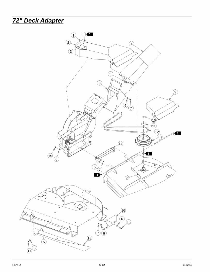
72" Deck Adapter
1
6
8
4
5
7
9
1011
1213
14
67
156
176
615
185
2
3
16
1
1
7 6
1
1

116274 6-13 REV D
72" Deck Adapter
NOTES:
1. Use existing parts and hardware.
INDEX NO. PART NO. QTY. DESCRIPTION
1 551038 1 72" BELT COVER W/ DECALS2 601624 1 DISCHARGE CHUTE DECAL3 601837 1 DECK DANGERS DECAL4 603324 1 BLOWER OUTLET TUBE5 025395 7 CB .375-16 X 1.00 G5 ZNY6 767954 13 FW .406 X .812 X .060 SAE7 054502 7 NT .375-16 HX GRD 5 ZNY8 114066 1 OUTLET ADAPTER9 114350 1 72" DBL PULLEY COVER
10 017616 1 CS .500-13 X 1.750 HX G5 11 752386 1 CW .515 X 2.25 X .204 BLK12 602998 1 BELT, A 89.0" EL13 603313 1 72" DOUBLE DRIVE14 113118 1 BLOWER MOUNT15 036244 3 CS .375-16 X 1.000 HX G516 114077 1 72" BLOWER BAFFLE17 086660 3 NT .375-16 HXZY NL18 114363 1 RS 72" BLOWOUT BAFFLE

REV D 6-14 116274
Frame
2
1
4
63
3
3
2
5

116274 6-15 REV D
Frame
NOTES:
INDEX NO. PART NO. QTY. DESCRIPTION
1 115706 1 FRAME2 808485 4 RIVET NUT, 5/16-18 THREAD3 015495 3 GREASE FITTING STRAIGHT4 603940 2 DFS CATCHER DECAL5 603967 2 PINCH POINT DECAL6 808477 2 1/4-20 THREAD RIVET NUT

REV D 6-16 116274
Shell
2
4
3
1
3
3
16
2
5
6
56
56
56
7
8
10
9
12
13
11
10
1314
10
11
15
6
5
6
SHELLFRAME
SHELL

116274 6-17 REV D
Shell
NOTES:
INDEX NO. PART NO. QTY. DESCRIPTION
1 603794 1 LINEAR ACTUATOR2 781567 2 NT .500-13 HX G8 ZY NL3 767962 8 FW .531 X 1.063 X .090 SAE4 721910 1 CS .500-13 X 2.75 HX G5 Z5 058776 29 NT .312-18 HXZY NL6 768523 29 FW .343 X .687 X .051/.080H7 603796 1 SHELL8 115875 1 INLET TUBE9 115785 1 TOP BAFFLE
10 037887 13 CB .312-18 X 1.000 FULL ZN11 115782 2 SIDE BAFFLE12 115878 1 INSIDE CORNER13 016253 16 CB .312-18 X .750 FUL ZN14 115701 4 VERTICAL SPANNER15 115740 1 SKID PLATE16 077859 1 CS .500-13 X 3.250 HX G5
REV D 6-18 116274
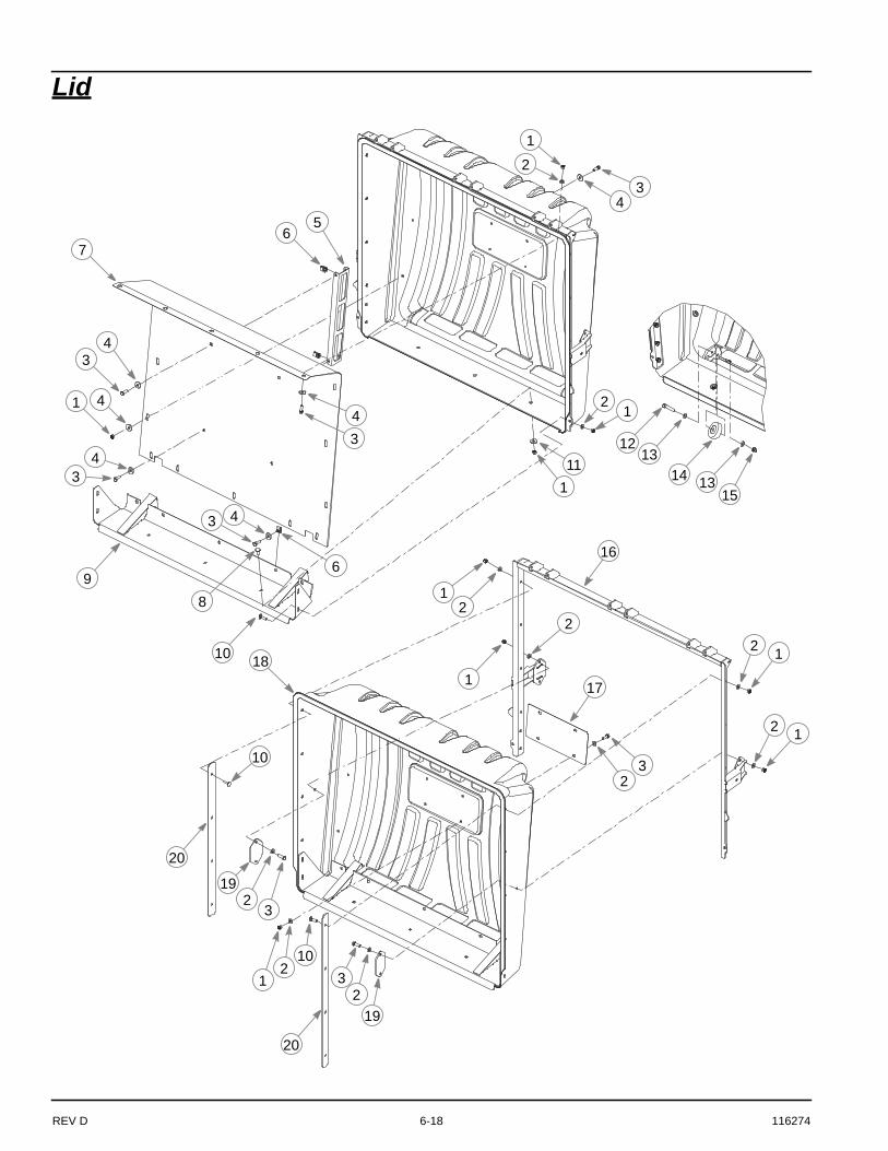
Lid
18
1
6
3
2
9
17
4
12
4
43
21
111
43
8
7
10
1213
14 1315
12
1
22 1
3
16
10
32
23
19
2 1
19
20
20
21
10
3
43
4
65

116274 6-19 REV D
Lid
NOTES:
INDEX NO. PART NO. QTY. DESCRIPTION
1 058776 34 NT .312-18 HXZY NL2 768523 33 FW .343 X .687 X .051/.080H3 036236 28 CS .312-18 X 1.000 HX G54 712927 26 FW .344 X 1.00 X .12 HRD ZN5 115919 2 SPACER6 601069 9 CN .312-18 X .200 MAX THK7 115882 1 SCREEN8 016253 3 CB .312-18 X .750 FUL ZN9 115846 1 BOTTOM PLATE
10 037887 12 CB .312-18 X 1.000 FULL ZNYC11 079210 3 FW .344 X 1.00 X .06 ZN12 705178 2 CS .375-16 X 1.750 HX G513 767954 4 FW .406 X .812 X .060 SAE14 760181 2 WHEEL15 086660 2 NT .375-16 HXZY NL16 115723 1 LID FRAME17 789453 1 LICENSE PLATE18 603797 1 LID19 116116 2 ANCHOR BRACKET20 115783 2 SIDE BAFFLE

REV D 6-20 116274
Linkage
3
2
6
1
4
2
5
8
72
2
3
5
SHELL ASSEMBLY
LIDASSEMBLY
116274 6-21 REV D
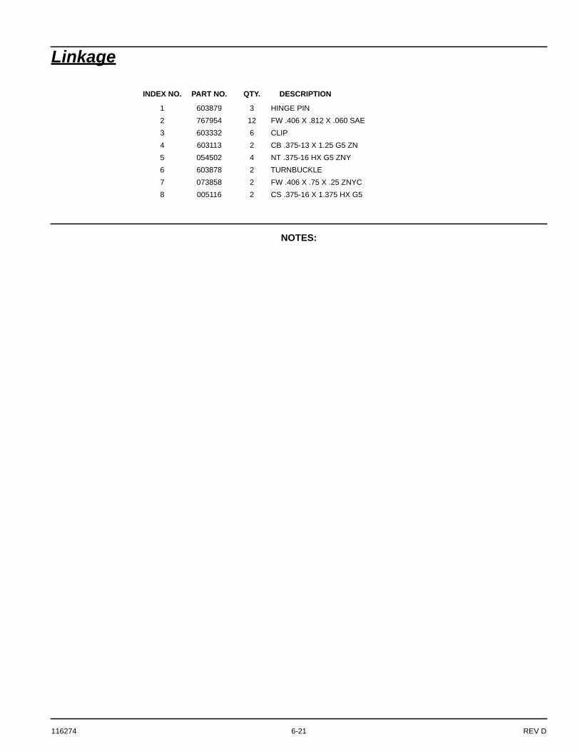
Linkage
NOTES:
INDEX NO. PART NO. QTY. DESCRIPTION
1 603879 3 HINGE PIN2 767954 12 FW .406 X .812 X .060 SAE3 603332 6 CLIP4 603113 2 CB .375-13 X 1.25 G5 ZN5 054502 4 NT .375-16 HX G5 ZNY6 603878 2 TURNBUCKLE7 073858 2 FW .406 X .75 X .25 ZNYC8 005116 2 CS .375-16 X 1.375 HX G5
REV D 6-22 116274
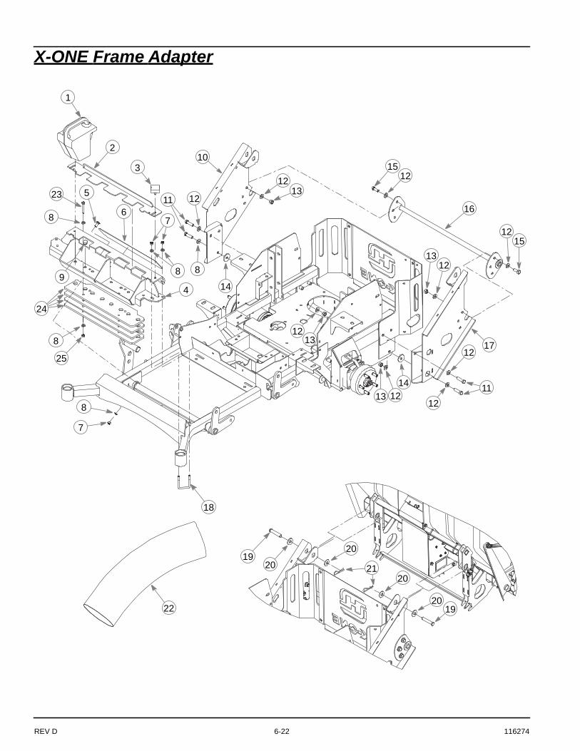
X-ONE Frame Adapter
9
20
19
1
8
18
20
20
16
2
12
4
3
5
7
8
1213
11 12
8
14
7
21
2019
10
1213
13 1212
1114
1512
1215
1312
17
6
22
23
8
25
24
8

116274 6-23 REV D
X-ONE Frame Adapter
NOTES:
INDEX NO. PART NO. QTY. DESCRIPTION
1 603207 4 WEIGHT2 114323 1 WEIGHT LOCK PLATE3 792002 2 KNOB 5/16-18 X 3/4"4 114327 1 WEIGHT MOUNT5 025395 2 CB .375-16 X 1.00 G5 ZNY6 602323 1 STEP TREAD7 086660 6 NT .375-16 HXZY NL8 767954 14 FW .406 X .812 X .060 SAE9 781880 8 BUMPER
10 115789 1 RS MOUNT11 017616 6 CS .500-13 X 1.75 HX G5 12 767962 20 FW .531 X 1.063 X .090 SAE13 008193 8 NT .500-13 HX G5 ZNYC14 078386 2 FW .510 X 1.75 X .18 ZNYC15 705954 6 CS .500-13 X 1.25 HX G5 ZN 16 115790 1 MOUNT SPACER17 115787 1 LS MOUNT18 603339 2 UB .375-16 X 2.00 X 3.00 SQ19 053702 2 CE .620 X 3.0 X .15 X 2.8420 704783 4 FW .625 X 1.50 X .105 ZN21 023036 2 HP .148 X 2.69 ZN22 603357 1 FLEX TUBE23 016428 4 CS .375-16 X 2.50 HX GR524 114661 4 WEIGHT PLATE25 054502 4 NT .375-16 HX G5 ZN

REV D 6-24 116274
Super Z Frame Adapter
9
20
19
1
8
18
20
20
16
2
12
4
3
5
7
8
121311 12
814
7
21
2019
10
1213
1312 12
1114
1512
121513
12
17
6
22

116274 6-25 REV D
Super Z Frame Adapter
NOTES:
INDEX NO. PART NO. QTY. DESCRIPTION
1 603207 4 WEIGHT2 114323 1 WEIGHT LOCK PLATE3 792002 2 KNOB 5/16-18 X 3/4"4 114317 1 WEIGHT MOUNT5 025395 2 CB .375-16 X 1.00 G5 ZNY6 602323 1 STEP TREAD7 086660 6 NT .375-16 HXZY NL8 767954 6 FW .406 X .812 X .060 SAE9 781880 8 BUMPER
10 115733 1 RS MOUNT11 017616 6 CS .500-13 X 1.750 HX G5 12 767962 20 FW .531 X 1.063 X .090 SAE13 008193 8 NT .500-13 HX G5 ZNYC14 078386 2 FW .510 X 1.750 X .18 ZNYC15 705954 6 CS .500-13 X 1.250 HX G5 ZN 16 115748 1 MOUNT SPACER17 115732 1 LS MOUNT18 603340 2 UB .375-16 X 2.00 X 4.00 SQ19 053702 2 CE .620 X 3.0 X .15 X 2.8420 704783 4 FW .625 X 1.5000 X .105 ZN21 023036 2 HP .148 X 2.690 ZN22 603356 1 FLEX TUBE

REV D 6-26 116274
Shell Electric
4
2
7
3
13
53
1
1 6
89
10
11
109
76
43
2
34
1
2
4
3
12
4
14
1415
16
15
1
17
SHELL ASSEMBLY
SHELL FRAME
18

116274 6-27 REV D
Shell Electric
NOTES:
1. Part of wire harness.
INDEX NO. PART NO. QTY. DESCRIPTION
1 115711 1 ACTUATOR TOP LID2 808485 5 5/16-18 THREAD RIVET NUT3 034280 9 CS .312-18 X .75 HX G54 768523 9 FW .343 X .687 X .051/.080H5 116213 1 CONTROL BOX COVER6 601822 2 NUT PLATE .420 CENTERS7 603937 2 PLUNGER SWITCH8 116200 1 CONTROL BOX SWITCH9 768515 2 FW .281 X .625 X .051/.080 HD ZN/YL
10 064329 2 CS .250-20 X .625 HX G511 063198 4 CS 10-24 X .75 HX FLK ZN12 000331 4 WIRE TIE13 603936 1 WIRE HARNESS14 059832 3 NT #10-24 HX NL ZN15 017079 3 FW .250 X .56 X .04 SAE Z16 060731 3 CS 10-24 X .50 HX FLK ZN17 115731 1 ACTUATOR BOTTOM LID18 N/A 1 SERIAL NO. / SPEC DECAL
REV D 6-28 116274
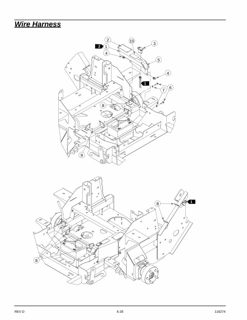
Wire Harness
8
5
2
1
14
4
67
3
8
8
1
9
210

116274 6-29 REV D
Wire Harness
NOTES:
1. Part of wire harness.2. Frame cover usage:
INDEX NO. PART NO. QTY. DESCRIPTION
1 551515 1 FRAME COVER (WITH DECALS & CLIP NUTS)551516 1 FRAME COVER (WITH DECALS & CLIP NUTS)
2 600899 1 PUMP BELT WARNING DECAL3 797308 1 SWITCH4 601069 3 CN .312-18 X .200 MAX THK5 785139 1 LS STEERING DECAL6 036236 3 CS .312-18 X 1.000 HX G57 768523 3 FW .343 X .687 X .051/.080H8 000331 7 WIRE TIE, SMALL/SHORT9 603935 1 WIRE HARNESS
10 604049 1 HOPPER POSITION DECAL
551515 USED ON SUPER Z
551516 USED ON X-ONE
REV D 6-30 116274
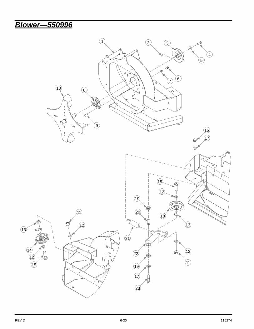
Blower—550996
45
321
67
10 8
9
12
11
15
12
13
14
16
11
18
19
22
17
20
13
12
15
21
12
23
17
19

116274 6-31 REV D
Blower—550996
NOTES:
INDEX NO. PART NO. QTY. DESCRIPTION
1 N/A 1 BLOWER HOUSING (NOT SOLD SEPARATELY)2 322529 1 KEY .187 SQ X .75 LONG3 602912 1 PULLEY4 036244 3 CS .375-16 X 1.00 HX G55 712919 1 FW .406 X 1.00 X .12 HRD Z6 058776 10 NT .312-18 HX ZY NL7 768523 11 FW .343 X .687 X .051/.080H8 604264 2 BEARING 1.0" BORE FLANGE9 016253 10 CB .312-18 X .75 FUL ZN
10 119510 1 BLOWER IMPELLER11 016972 2 NT .625-11 HX G5 ZNYC12 028118 4 FW .625 X 1.00 X .134 ZNYC13 600296 3 DECK IDLER SPACER14 791566 1 IDLER PULLEY 3.25" OD X .615 016642 2 CS .625-11 X 2.00 HX G5 Z16 781567 1 NT .500-13 HX G8 ZY NL17 767962 2 FW .531 X 1.063 X .090 SAE18 602913 1 V-IDLER PULLEY19 770867 2 BUSHING20 109549 1 BUSHING21 036384 1 SPRING 1/4 COIL PL 1.2322 113406 1 BLOWER IDLER ARM23 008573 1 CS .500-13 X 2.50 HX G5

REV D 6-32 116274
Blower—55099624
76
268
930
29
277
28
34
35
313233
4 36
37
31
38
39
42
4643
40
31
41
42
44
40
25
47
45

116274 6-33 REV D
Blower—550996
NOTES:
INDEX NO. PART NO. QTY. DESCRIPTION
24 114337 1 BEARING COVER25 113119 1 BLOWER COVER26 799130 8 CS .312-18 X .50 HXFL27 792002 1 KNOB 5/16-18 X 3/4"28 036236 1 CS .312-18 X 1.00 HX G529 114338 1 DRIVEN PULLEY COVER30 601069 2 CN .312-18 X .20 MAX THK31 086660 5 NT .375-16 HX ZY NL32 073858 2 FW .406 X .75 X .25 ZNYC33 602674 1 CB .375-16 X 6.00 STD34 602757 1 BLOWER DANGERS DECAL35 N/A 1 SERIAL NO. / SPEC DECAL36 704718 2 FW .406 X .688 X .060 ZNYC37 602435 1 TORSION SPRING38 550995 1 BLOWER LID (WITH DECALS)39 602758 1 EYES/EARS/FOOT DECAL40 767954 3 FW .406 X .812 X .060 SAE41 603191 1 BLOWER CHUTE INLET42 025395 3 CB .375-16 X 1.00 G5 ZNY43 113128 1 BLOWER INLET BAFFLE44 054502 1 NT .375-16 HX G5 ZNY45 076422 2 FW .406 X 1.00 X .06 ZNYC46 774919 2 CS .375-16 X .50 SOC BH47 550996 1 BLOWER ASSEMBLY

REV D 6-34 116274
116274 i-1 REV D
INDEXPAGE PAGE
BAC-VAC™ Assembly ....................................3-14
BAC-VAC™ Hopper ........................................5-2
BAC-VAC™ Hopper Switch Adjustment ...........5-2
BAC-VAC™ Mount Assembly ..........................3-9
Blower Drive Belt ............................................5-1
Blower Housing and Flex Tube Maintenance ...5-1
Blower Impeller ...............................................5-3
Converting to side discharge mode..................4-1
Deck adapter kits ............................................3-1
Final Connection.............................................3-11
Frame Cover Assembly Installation .................3-9
Lid latch adjustment ........................................5-3
Mower deck preparation ..................................3-2
Mower Preparation..........................................3-8
Packing List - Hustler® Super Z BAC-VAC™ ...3-1
Packing List – Hustler® X-ONE BAC-VAC™ ....3-1
Parts and service ............................................1-1
Removing The BAC-VAC™ .............................4-2
Storage ..........................................................5-3
To the new owner ...........................................1-1
Unloading the BAC-VAC™ ..............................4-1
Using this manual ...........................................1-1
Vacuum Pickup and Collection ........................4-1
Warranty registration.......................................1-1
Weight Assembly ............................................3-15
000331 ...........................................................3-1, 6-29
008193 ...........................................................3-1, 3-9, 6-23, 6-25
008573 ...........................................................3-5, 6-9
016428 ...........................................................3-1, 3-14, 6-23
017616 ...........................................................3-1, 3-3, 3-4, 3-6, 3-7, 3-9, 6-3, 6-5, 6-7, 6-11, 6-13, 6-23, 6-25
023036 ...........................................................3-1, 6-23, 6-25
025395 ...........................................................3-1, 3-3, 3-4, 3-5, 3-6, 3-7, 3-15, 6-3,
6-5, 6-7, 6-9, 6-11, 6-13, 6-23, 6-25
036236 ...........................................................3-1, 6-29
036244 ...........................................................3-3, 3-4, 3-5, 3-6, 3-7, 6-3, 6-5, 6-7, 6-9, 6-11, 6-13
045765 ...........................................................3-5, 6-9
053702 ...........................................................3-1, 3-14, 6-23, 6-25
054502 ...........................................................3-3, 3-4, 3-5, 3-6, 3-7, 3-14, 6-3, 6-5, 6-7, 6-9, 6-11, 6-13, 6-23
078386 ...........................................................3-1, 3-9, 6-23, 6-25
086660 ...........................................................3-1, 3-3, 3-4, 3-5, 3-6, 3-7, 3-15, 6-3, 6-5, 6-7, 6-9, 6-11, 6-13, 6-23, 6-25
113118 ...........................................................3-4, 3-5, 3-6, 3-7, 6-7, 6-9, 6-11, 6-13
113127 ...........................................................3-4, 3-5, 6-7, 6-9
113900 ...........................................................3-1
113900 & 113901 Adapter Assembly ...............3-3
113901 ...........................................................3-1
113902 ...........................................................3-1
113902 Adapter Assembly...............................3-4
113903 ...........................................................3-1
113903 Adapter Assembly...............................3-5
113904 ...........................................................3-1
113904 Adapter Assembly...............................3-6
113905 ...........................................................3-1
113905 Adapter Assembly...............................3-7
114066 ...........................................................3-3, 3-6, 3-7, 6-3, 6-5, 6-7, 6-9, 6-11, 6-13

REV D i-2 116274
PAGE PAGE114068 ...........................................................3-3, 6-3
114071 ...........................................................3-3, 6-5
114074 ...........................................................3-6, 6-11
114077 ...........................................................3-7, 6-13
114169 ...........................................................3-14
114194 ...........................................................3-3, 6-3, 6-5
114317 ...........................................................3-15, 6-25
114323 ...........................................................3-15, 6-23, 6-25
114327 ...........................................................3-14, 3-15, 6-23
114349 ...........................................................3-6, 6-11
114350 ...........................................................3-7, 6-13
114359 ...........................................................3-3, 6-3
114360 ...........................................................3-3, 6-5
114361 ...........................................................3-4, 3-5, 6-7, 6-9
114362 ...........................................................3-6, 6-11
114363 ...........................................................3-7, 6-13
114388 ...........................................................3-3, 6-3
114389 ...........................................................3-3, 6-5
114661 ...........................................................3-1, 3-14, 6-23
115665 ...........................................................3-4, 3-5, 6-7, 6-9
115732 ...........................................................3-1, 3-9, 6-25
115733 ...........................................................3-1, 3-9, 6-25
115748 ...........................................................3-1, 3-9, 6-25
115773 ...........................................................3-4, 3-5, 6-7, 6-9
115787 ...........................................................3-1, 3-9, 6-23
115789 ...........................................................3-1, 3-9, 6-23
115790 ...........................................................3-1, 3-9, 6-23
550996 ...........................................................3-1
551034 ...........................................................3-3, 6-3
551035 ...........................................................3-3, 6-5
551037 ...........................................................3-6, 6-11
551038........................................................... 3-7, 6-13
551305........................................................... 3-4, 3-5, 6-7, 6-9
551515........................................................... 6-29
551516........................................................... 6-29
600899........................................................... 6-29
601069........................................................... 3-3, 3-4, 3-5, 6-3, 6-5, 6-7, 6-9, 6-29
601624........................................................... 3-3, 3-4, 3-5, 3-6, 3-7, 6-3, 6-5, 6-7, 6-9, 6-11, 6-13
601837........................................................... 3-3, 3-4, 3-5, 3-6, 3-7, 6-3, 6-5, 6-7, 6-9, 6-11, 6-13
602323........................................................... 6-23, 6-25
602914........................................................... 3-5, 6-9
602997........................................................... 3-6, 6-11
602998........................................................... 3-7, 6-13
603207........................................................... 3-15, 6-23, 6-25
603213........................................................... 3-3, 6-3, 6-5, 6-7
603309........................................................... 3-3, 6-3
603310........................................................... 3-3, 6-5
603311........................................................... 3-4, 6-7
603312........................................................... 3-6, 6-11
603313........................................................... 3-7, 6-13
603318........................................................... 3-3, 6-3
603319........................................................... 3-3, 6-5
603324........................................................... 3-6, 3-7, 6-9, 6-11, 6-13
603339........................................................... 3-1, 3-15, 6-23
603340........................................................... 3-1, 3-15, 6-25
603356........................................................... 3-1, 6-25
603357........................................................... 3-1, 6-23
603806........................................................... 3-4, 3-5, 6-7, 6-9
603935........................................................... 3-1, 6-29
604049........................................................... 6-29

116274 i-3 REV D
INDEXPAGE PAGE
704783 ...........................................................3-1, 3-14, 6-23, 6-25
705954 ...........................................................3-1, 3-9, 6-23, 6-25
752386 ...........................................................3-3, 3-4, 3-5, 3-6, 3-7, 6-3, 6-5, 6-7, 6-9, 6-11, 6-13
767954 ...........................................................3-1, 3-3, 3-4, 3-5, 3-6, 3-7, 3-14, 3-15, 6-3, 6-5, 6-7, 6-9, 6-11, 6-13, 6-23, 6-25
767962 ...........................................................3-1, 3-9, 6-23, 6-25
768523 ...........................................................3-1, 6-29
781880 ...........................................................3-15, 6-23, 6-25
785139 ...........................................................6-29
792002 ...........................................................3-3, 3-4, 3-5, 3-15, 6-3, 6-5, 6-7, 6-9, 6-23, 6-25
797308 ...........................................................6-29


