34
Tasmanian Networks Pty Ltd (ABN 24 167 357 299) Standard High Voltage (HV) Shunt Capacitor Bank Standard R522695 Version 1.0, June 2018
Tasmanian Networks Pty Ltd (ABN 24 167 357 299)
Standard
High Voltage (HV) Shunt Capacitor Bank Standard
R522695
Version 1.0, June 2018
Tasmanian Networks Pty Ltd (ABN 24 167 357 299)
AuthorisationsAction Name and title DatePrepared by Michael Verrier, Senior Asset Strategy Engineer June 2018
Reviewed bySantosh Dhakal, Asset Engineer June 2018
Authorised by Darryl Munro, Asset Strategy Team Leader June 2018Review cycle 30 months
ResponsibilitiesThis document is the responsibility of the Asset Strategy Team, Tasmanian Networks Pty Ltd, ABN 24 167 357 299 (hereafter referred to as "TasNetworks") .
Please contact the Asset Strategy Leader with any queries or suggestions.
• Implementation All TasNetworks staff and contractors.
• Compliance All group managers.
Minimum RequirementsThe requirements set out in TasNetworks ’ documents are minimum requirements that must be compliedwith by all TasNetworks team members, contractors, and other consultants.
The end user is expected to implement any practices which may not be stated but which can be reasonablyregarded as good practices relevant to the objective of this document.
© Tasmanian Networks Pty Ltd 2014
Page 3 of 34
HV Shunt Capacitor Bank Standard
Record of revisionsSection number Details
Entire doc Copied over verbatim from superseded Transend to TasNetworks template.Updated Transend to TasNetworks document reference numbers where knownincluding Australian Standards.

Page 4 of 34
HV Shunt Capacitor Bank Standard
Table of contentsAuthorisations...............................................................................................................................................2
Responsibilities............................................................................................................................................. 2
Minimum Requirements...............................................................................................................................2
List of tables..................................................................................................................................................6
1.....................................................................................................................................................General7
1.1..................................................................................................................................Purpose7
1.2..........................................................................................................................................Scope7
1.3................................................................................................................................Objective7
1.4.................................................................................................... Certificate of conformance7
1.5............................................................................................................................ Precedence8
1.6................................................................................................................................Deviation8
1.7............................................................................................................................. References8
1.7.1.......................................................................................................TasNetworks standards8
1.7.2.................................................................................................................. Other standards8
2..............................................................................................................................General Requirements9
2.1..................................................................................................................Service Conditions9
2.2.......................................................................................................................... Performance9
3........................................................................................................................................Capacitor banks9
3.1...............................................................................................Application of capacitor banks9
3.2..........................................................................................................Capacitor bank concept10
3.3..............................................................General design requirements from capacitor banks10
Page 5 of 34
HV Shunt Capacitor Bank Standard
3.4...............................................................................Design requirements for capacitor banks10
4.....................................................................................................................Shunt capacitor and reactor11
4.1........................................................................Capacitor and reactor design and installation11
4.2.................................................................................................. Neutral current transformer13
4.3.....................................................................................................Capacitor bank installation14
4.4...........................................................................................................................Special tools16
4.5................................................................................................Documentation requirements16
4.6.....................................................................................................................................Labels16
4.7............................................................................................................................Nameplates17
5................................................................. Capacitor bank switching, protection and control equipment17
5.1.............................................................................................................General arrangement18
5.2........................................................................................................................Circuit breaker18
5.3........................................................................................................................... Earth switch18
5.4........................................................................................................Instrument transformers19
5.5.......................................................................................................................Surge diverters19
5.6............................................................................High voltage power cables and conductors19
5.7...........................................................................................................Protection and control19
5.8................................................................................................................................ Metering20
5.9..................................................................................................................Alarms and events20
5.10.........................................................................................Connections to SCADA and NOCS20
6...........................................................................................................................................Cable systems20

Page 6 of 34
HV Shunt Capacitor Bank Standard
7................................................................................................................................................ Civil works21
8....................................................................................................................................................Earthing21
9.................................................................................... Data for Asset Management Information System21
10.......................................................................................................Maintenance procedures and plans21
11....................................................................................................................................................Testing21
11.1.............................................................................................................................Type tests22
11.2........................................................................................................................Routine tests22
11.3.........................................................................Pre-commissiong and Commissioning tests22
12................................................................................................................................................Packaging23
13.................................................................................................Information to be provided with tender23
14............................................................................................................................................Deliverables23
15.............................................................................................................................................Hold points23
Appendix A – Typical Capacitor Bank details for reference purposes.......................................................25
List of tablesTable 1.......................................................................... Parameters for capacitors and reactors
11
Table 2..................................................................Parameters for neutral current transformers14
Table 3.......................................................................................Parameters for circuit breakers18
Table 4..........................................................................Controls for capacitor bank from mimic20
Table 5...................................Alarm and event indications from capacitor bank to annunciator20
Table 6..........................Status indications from capacitor bank switching equipment to mimic20
Page 7 of 34
HV Shunt Capacitor Bank Standard
1 General
1.1 PurposeTo define the requirements for high voltage shunt capacitor banks under the responsibility of TasmanianNetworks Pty Ltd (hereafter referred to as ‘TasNetworks ’).
1.2 ScopeThis standard applies to all high voltage shunt capacitor banks under the responsibility of TasNetworks .
This standard contains requirements for design, engineering, manufacture, construction, testing atmanufacturer’s works, secured packaging, supply, transportation, delivery to site, testing and commissioningwith complete documentation of the capacitor bank and is to be applied to new installations as well asredevelopment of part or all of existing installations.
1.3 ObjectiveTasNetworks requires design, construction, installation and commissioning of equipment and services becovered by this standard to ensure:
(a) that relevant Australian legal requirements are met;
(b) that the requirements of the National Electricity Rules are met;
(c) personnel and public safety hazards are identified and control measures adopted;
(d) risk to TasNetworks’ assets is assessed;
(e) ease of operation and maintenance;
(f) reliability and continuity of electricity supply;
(g) that the requirements of the TasNetworks business plan are met;
(h) that the exposure of TasNetworks’ business to risk and loss is minimised; and
(i) that TasNetworks’ responsibilities under connection agreements are met.
1.1 Certificate of conformance(a) Before any new and/or modified capacitor bank is put into service in TasNetworks’ system, a
certificate of conformance with this standard must be submitted to TasNetworks . The certificate ofconformance must be duly supported with documents, drawings, test results, test reports, testcertificates, completed check-lists and other documents as applicable. Where TasNetworks hasapproved deviation to specific requirements of this standard, all such approvals must be included withthe certificate of conformance.
(b) TasNetworks will supply a blank form for certificate of conformance, to be completed by theContractor.
(c) A capacitor bank will be put in service only after TasNetworks has accepted the certificate ofconformance.
Page 8 of 34
HV Shunt Capacitor Bank Standard
1.1 PrecedenceAny conflict between the requirements of the codes, specifications, drawings, rules, regulations andstatutory requirements or various sections of this standard and other associated documents must bebrought to the attention of TasNetworks for resolution. The most onerous requirement will normally beapplied.
1.2 DeviationSpecial approval for a deviation to this standard may only be accorded, if it does not reduce the quality ofworkmanship and does not deviate from the intent of the standard. A request for a deviation must follow adesignated procedure that involves approval from TasNetworks . Deviations if any, must be specificallyrequested, and approved in writing by TasNetworks prior to award of Contract.
1.3 ReferencesAs a component of the complete specification for a system, this standard is to be read in conjunction withother standards and documents as applicable. In particular this includes the project specifications and thefollowing:
1.3.1 TasNetworks standardsSubstation Civil Design and Construction Standard R590634
Substation Lightning Protection and Earthing Standard R522692
General Substation Requirements Standard R522687
High Voltage System Standard R565983
Testing, Commissioning and Training Standard R246497
Security Fences and Gates Standard R579297
SCADA System Standard R246439
HV & LV Cable Systems Standard R590630
HV Shunt Capacitor Bank Schedule R579292
HV Shunt Capacitor Bank Deliverables R579291
Asset Nomenclature Standard R684808
Metering Standard D11/86620
1.3.2 Other standardsPower capacitors – Shunt – Rated voltages above 660 V ac AS 2897 – 1986
(IEC/TS 60871-2 Ed. 2.0)
Power transformers - reactors AS/NZS 60076.6:2003
Page 9 of 34
HV Shunt Capacitor Bank Standard
2 General RequirementsProject specific requirements for the capacitor bank will be listed in the project specifications.
2.1 Service ConditionsService conditions will not exceed the limits stated in AS 2897 – 1986, together with the particulars of thesystem stated in Table 1 of this standard.
Specific environmental conditions and any specific design, installation, operation or maintenance criteria forparticular works will be stated in the project specifications, such as availability of space, switchyard,switchboard and SCADA arrangements and any power quality performance criteria.
2.2 Performance(a) A capacitor bank and its individual components must provide reliable performance.
(b) The performance of the capacitor bank must meet all specified electrical, mechanical andenvironmental criteria under both normal and abnormal system conditions.
(c) The selection of equipment, design and all works associated with the capacitor banks must conform tothe requirements as specified in document R522687 and meet or exceed the specified design criteriaand performance stated within this standard.
(d) Details of maintenance items, their accessibility and the frequency of maintenance must be providedwith the tender.
3 Capacitor banksCapacitor banks are to be arranged in an unearthed double star configuration.
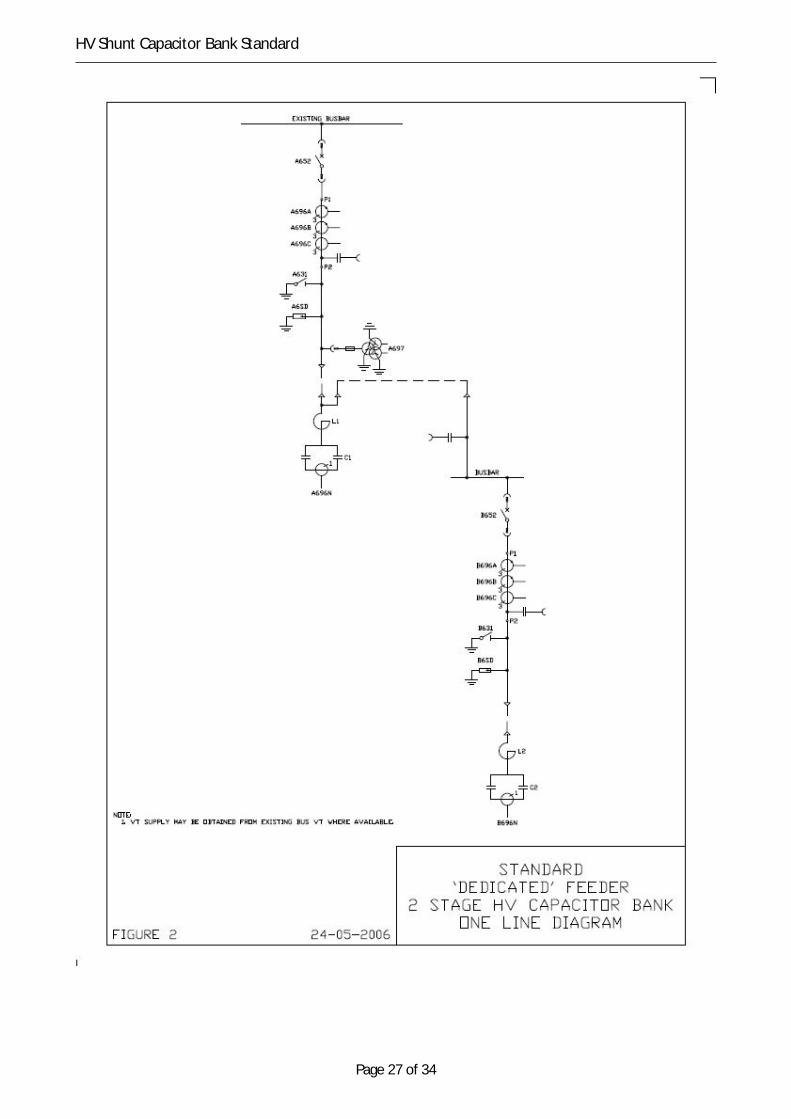
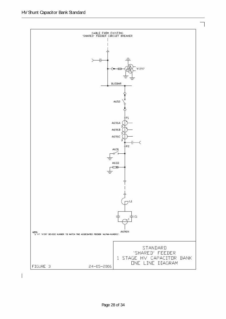
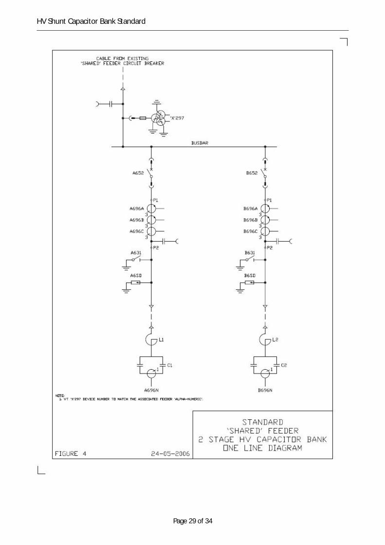
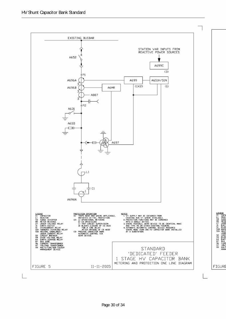
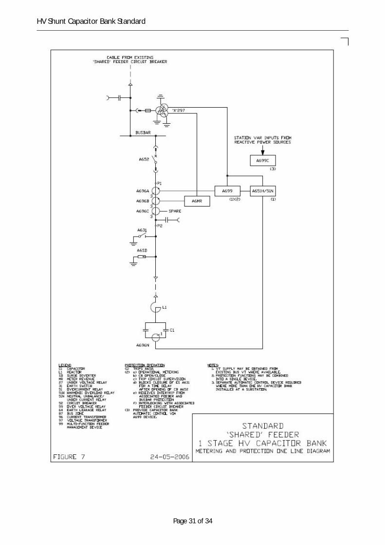
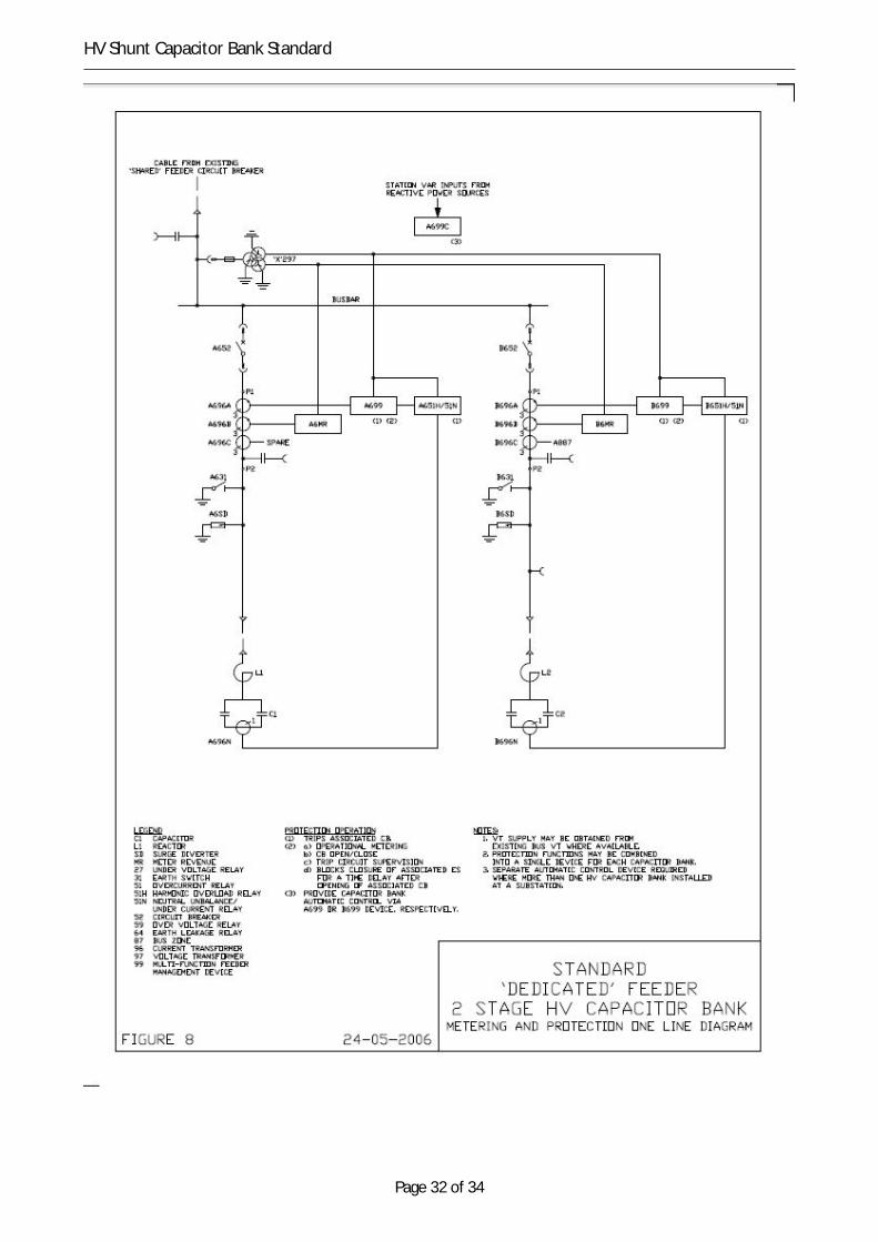
Conceptual diagrams for high voltage capacitor banks, with associated busbar connection equipment areattached, as follows:
• Figures 1 to 4 Power circuit one line diagrams.
• Figures 5 to 8 Metering and protection one line diagrams.
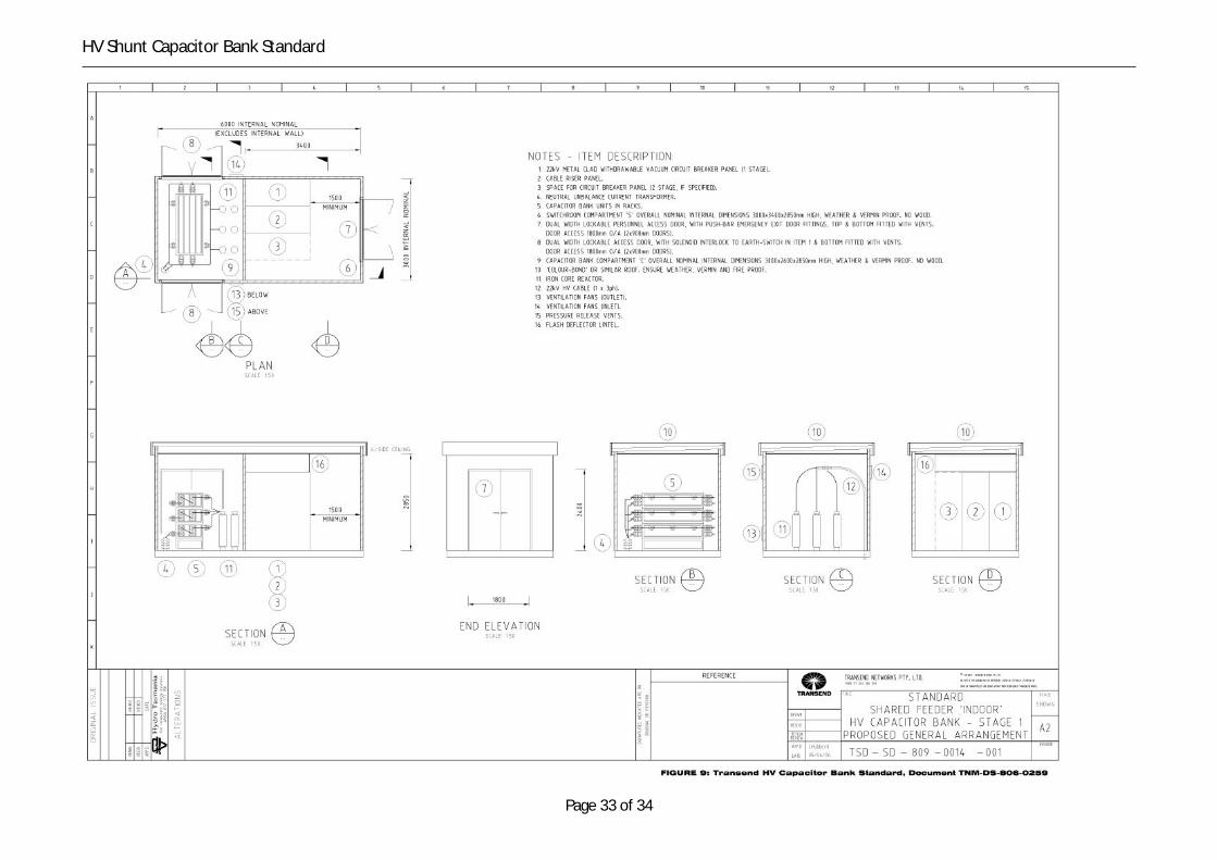
• Figure 9 to 10 General arrangement – plan and sections.
3.1 Application of capacitor banksShunt capacitor banks are installed to provide reactive power compensation to support voltages within theNational Electricity Rules requirements and to mitigate voltage collapse in specific regions. An additionaladvantages is power factor correction, and a subsequent reduction in transmission losses, with the potentialfor postponement of transmission or distribution investment.
Shunt capacitor banks are applied at various locations within the network. To ensure rationalisation ofrequirements, TasNetworks has standardised on specific types of high voltage shunt capacitor banksdependent on the rated voltage of the connection, as follows:
(a) Type One (1) – 24 kV, 5 MVAr outdoor.
(b) Type Two (2) – 24 kV, 5 MVAr indoor.
(c) Type Three (3) – 12 kV, 2.5 MVAr outdoor.
(d) Type Four (4) – 12 kV, 2.5 MVAr indoor.
Page 10 of 34
HV Shunt Capacitor Bank Standard
The service location shall be indoor (Type 2 or Type 4), unless stated differently within the projectspecifications.
3.1 Capacitor bank conceptEach capacitor bank shall comprise of:
(a) three only, single-phase reactors to both limit inrush current and detune harmonics, with eachreactor. Where iron-core reactors are utilised they must be mounted at ground level on a commonframe. Alternatively, where air-core reactors are utilised they must be stacked above each other andmounted on a common structure;
(b) an assembly of capacitor units arranged in parallel/series phase connected groups, with each phase ona separate mounting structure; and
(c) two insulated double-star, unearthed neutral connections;
(d) single-phase, neutral current transformer located between the star-point neutral connections forunbalance condition detection.
3.1 General design requirements from capacitor banksMaterials and components must be selected to ensure safe and reliable operation for at least 45 years, withminimum inspection and maintenance.
The capacitor bank must be designed to:
(a) permit operational earthing to be applied effectively without compromising safe work clearances andto allow effective capacitor discharge;
(b) enable maintenance of the capacitor bank, including protection and control systems to be performedsafely and efficiently;
(c) allow filters and ventilation grills to be inspected, cleaned and replaced without the need for isolatingand earthing;
(d) demonstrate the incorporation of modern design and insulation material, together with intelligent,multi-function protection, control and monitoring technology;
(e) work in parallel with one or more existing or future capacitor banks in close electrical proximity;
(f) interface with existing dc supplies, SCADA, mimic, alarm annunciator and bus-zone and circuit breakerfailure scheme;
(g) ensure heating and ventilation is provided to ensure a capacitor bank can operate at rated capacitywithin rated temperature limits;
(h) ensure position indicators, pressure monitors and rating plates are visible from ground level;
(i) where outdoor, provide lightning protection (mast only) to shield the installation; and
(j) provide ac lighting and power supplies, with at least one single phase 10 A double GPO, to facilitatemaintenance.
3.1 Design requirements for capacitor banksCapacitor banks must be designed such that:
(a) individual capacitor units are appropriately sealed and finished to permit outdoor operation, exposedto both direct sunlight and wet weather conditions;
Page 11 of 34
HV Shunt Capacitor Bank Standard
(b) the impregnant fluid must be biodegradable and must not contain polychlorinated-biphenyl (PCB) orany derivatives;
(c) capacitor units must utilise aluminium foil with folded edges and polypropylene di-electric film with a‘hazy’ surface;
(d) the capacitor bank, individual components and earthing system must be of robust construction andcapable of withstanding the mechanical forces from thermal expansion and contraction;
(e) the capacitor bank’s switchboard, circuit breaker and earthing system must be appropriately rated towithstand the specified minimum short-circuit withstand current rating for at least one second. Powercables, capacitor cans and reactors must be appropriately rated to at least withstand the short-circuitcurrents that can be supplied by the existing high voltage system;
(f) capacitor units, conductors and fittings must have over-voltage, over-current and overload capabilitiesto withstand continuous operation at above rated voltage as per AS 2897 Section 4; and
(g) detuned capacitor bank reactors must be rated for continuous duty as per AS/NZS 60076.6.
4 Shunt capacitor and reactor
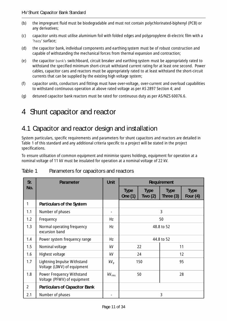
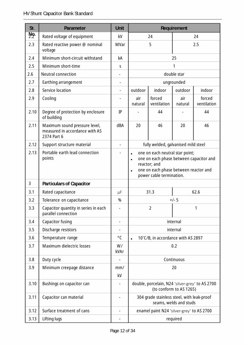
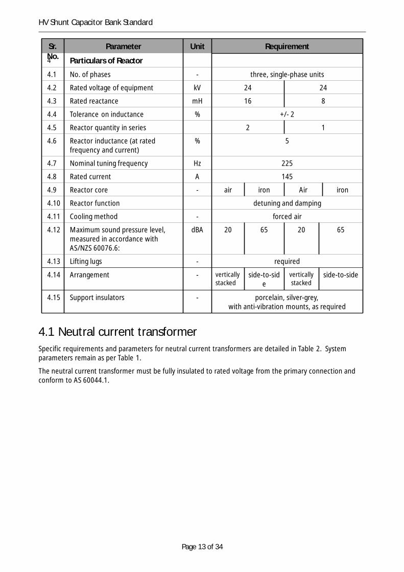
4.1 Capacitor and reactor design and installationSystem particulars, specific requirements and parameters for shunt capacitors and reactors are detailed inTable 1 of this standard and any additional criteria specific to a project will be stated in the projectspecifications.
To ensure utilisation of common equipment and minimise spares holdings, equipment for operation at anominal voltage of 11 kV must be insulated for operation at a nominal voltage of 22 kV.
Table 1 Parameters for capacitors and reactors
Sr.No.
Parameter Unit Requirement
TypeOne (1)
TypeTwo (2)
TypeThree (3)
TypeFour (4)
1 Particulars of the System
1.1 Number of phases - 3
1.2 Frequency Hz 50
1.3 Normal operating frequencyexcursion band
Hz 48.8 to 52
1.4 Power system frequency range Hz 44.8 to 52
1.5 Nominal voltage kV 22 11
1.6 Highest voltage kV 24 12
1.7 Lightning Impulse WithstandVoltage (LIWV) of equipment
kVp 150 95
1.8 Power Frequency WithstandVoltage (PFWV) of equipment
kVrms 50 28
2 Particulars of Capacitor Bank
2.1 Number of phases - 3
Page 12 of 34
HV Shunt Capacitor Bank Standard
Sr.No.
Parameter Unit Requirement
2.2 Rated voltage of equipment kV 24 24
2.3 Rated reactive power @ nominalvoltage
MVar 5 2.5
2.4 Minimum short-circuit withstand kA 25
2.5 Minimum short-time s 1
2.6 Neutral connection - double star
2.7 Earthing arrangement - ungrounded
2.8 Service location - outdoor indoor outdoor indoor
2.9 Cooling - airnatural
forcedventilation
airnatural
forcedventilation
2.10 Degree of protection by enclosureof building
IP - 44 - 44
2.11 Maximum sound pressure level,measured in accordance with AS2374 Part 6
dBA 20 46 20 46
2.12 Support structure material - fully welded, galvanised mild steel
2.13 Portable earth lead connectionpoints
- • one on each neutral star point;• one on each phase between capacitor and
reactor; and• one on each phase between reactor and
power cable termination.
3 Particulars of Capacitor
3.1 Rated capacitance μF 31.3 62.6
3.2 Tolerance on capacitance % +/- 5
3.3 Capacitor quantity in series in eachparallel connection
- 2 1
3.4 Capacitor fusing - internal
3.5 Discharge resistors - internal
3.6 Temperature range ºC • 10ºC/B, in accordance with AS 2897
3.7 Maximum dielectric losses W/kVAr
0.2
3.8 Duty cycle - Continuous
3.9 Minimum creepage distance mm/
kV
20
3.10 Bushings on capacitor can - double, porcelain, N24 ‘silver-grey’ to AS 2700(to conform to AS 1265)
3.11 Capacitor can material - 304 grade stainless steel, with leak-proofseams, welds and studs
3.12 Surface treatment of cans - enamel paint N24 ‘silver-grey’ to AS 2700
3.13 Lifting lugs - required
Page 13 of 34
HV Shunt Capacitor Bank Standard
Sr.No.
Parameter Unit Requirement
4 Particulars of Reactor
4.1 No. of phases - three, single-phase units
4.2 Rated voltage of equipment kV 24 24
4.3 Rated reactance mH 16 8
4.4 Tolerance on inductance % +/- 2
4.5 Reactor quantity in series 2 1
4.6 Reactor inductance (at ratedfrequency and current)
% 5
4.7 Nominal tuning frequency Hz 225
4.8 Rated current A 145
4.9 Reactor core - air iron Air iron
4.10 Reactor function detuning and damping
4.11 Cooling method - forced air
4.12 Maximum sound pressure level,measured in accordance withAS/NZS 60076.6:
dBA 20 65 20 65
4.13 Lifting lugs - required
4.14 Arrangement - verticallystacked
side-to-side
verticallystacked
side-to-side
4.15 Support insulators - porcelain, silver-grey,with anti-vibration mounts, as required
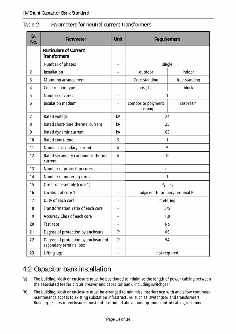
4.1 Neutral current transformerSpecific requirements and parameters for neutral current transformers are detailed in Table 2. Systemparameters remain as per Table 1.
The neutral current transformer must be fully insulated to rated voltage from the primary connection andconform to AS 60044.1.
Page 14 of 34
HV Shunt Capacitor Bank Standard
Table 2 Parameters for neutral current transformers
Sr.No. Parameter Unit Requirement
Particulars of CurrentTransformers
1 Number of phases - single
2 Installation - outdoor indoor
3 Mounting arrangement - Free-standing free-standing
4 Construction type - post, bar block
5 Number of cores - 1
6 Insulation medium - composite polymericbushing
cast-resin
7 Rated voltage kV 24
8 Rated short-time thermal current kA 25
9 Rated dynamic current kA 63
10 Rated short-time S 1
11 Nominal secondary current A 5
12 Rated secondary continuous thermalcurrent
A 10
13 Number of protection cores - nil
14 Number of metering cores - 1
15 Order of assembly (core 1) - P1 – P2
16 Location of core 1 - adjacent to primary terminal P1
17 Duty of each core - metering
18 Transformation ratio of each core - 5/5
19 Accuracy Class of each core - 1.0
20 Test taps - No
21 Degree of protection by enclosure IP 66
22 Degree of protection by enclosure ofsecondary terminal box
IP 54
23 Lifting lugs - not required
4.2 Capacitor bank installation(a) The building, kiosk or enclosure must be positioned to minimise the length of power cabling between
the associated feeder circuit breaker and capacitor bank, including switchgear.
(b) The building, kiosk or enclosure must be arranged to minimise interference with and allow continuedmaintenance access to existing substation infrastructure, such as, switchgear and transformers.Buildings, kiosks or enclosures must not positioned above underground control cables, incoming

Page 15 of 34
HV Shunt Capacitor Bank Standard
transformer and outgoing feeder power cables, oil containment system, storm water, fire-fightingwater and general water supply pipes.
(c) The internal layout, material and location of the capacitor bank building, kiosk or enclosure must beclearly marked on the substation general arrangement drawing and provided to TasNetworks forreview and approval.
(d) The capacitors, reactors and neutral current transformer must be effectively screened off from anyswitching or operating area.
(e) The reactors must be positioned with adequate clearance to minimise the heating and loss effect ofmagnetic fields on adjacent electrical equipment and metallic structures.
(f) The switchgear, capacitors, reactor and neutral current transformer must be installed within afree-standing building, or kiosk, with concrete floor and cable ducts, with cladding and roof to conformto TasNetworks’ Substation Civil Infrastructure Standard, R590634, suitable for a service life of at least45 years without replacement of structural material and at least 30 years without the need forreplacement of cover panels. The cladding and roof must not require repainting for the duration ofthe service life.
(g) All necessary connections, cabling, post-insulators, clamps, nuts, bolts and washers shall be suppliedto complete the erection of the capacitor bank, ready for service.
(h) Separate compartments must be provided for each capacitor bank step (module ‘C’) and for theswitchgear (module ‘S’), with separate external access doors for each module ‘C’ and for module ‘S’.Door fittings must be provided to allow safe egress from all compartments.
(i) Alternatively, where an outdoor installation is specified, the capacitors, reactors and neutral currenttransformer must be installed on support structures on a concrete plinth within a safety fenceenclosure. A concrete pad must cover all areas within the enclosure to minimise maintenancerequirements. Where an outdoor installation is specified, a building or kiosk must be always beprovided for the switchgear (module ‘S’).
(j) A compartment or an enclosure for each capacitor bank step must not be utilised for installation ofany other equipment other than the associated reactor, capacitor and neutral current transformer.
(k) The capacitor compartment must be lockable, leak-proof and vermin-proof and have ventilation,heating, lighting and access doors for safe and reliable operation and all-weather maintenance,including doors or removable panels to allow for ease of removal and repair of capacitors, reactorsand switchgear. Pressure-relief vents must be provided and positioned at a minimum height of 2.4 mto direct any arc fault pressure upwards.
(l) Climatic control must conform to TasNetworks’ Substation Civil Design and Construction Standard,R590634
(m) Hinged access doors must be fitted with an automatic closing device and a restraint to hold the doorin the fully open position of at least 120 degrees in the presence of high winds.
(n) Access doors to the capacitor compartment or access gates to an enclosure must be lockable andinterlocked with the earthing switch to prevent access to the capacitor bank equipment andassociated conductors, while the capacitor bank is unearthed, and to prevent the earth switch fromopening whilst the door or gate remains open.
(o) Adequate access and clearance must be provided for safe application of portable earth leads.
Page 16 of 34
HV Shunt Capacitor Bank Standard
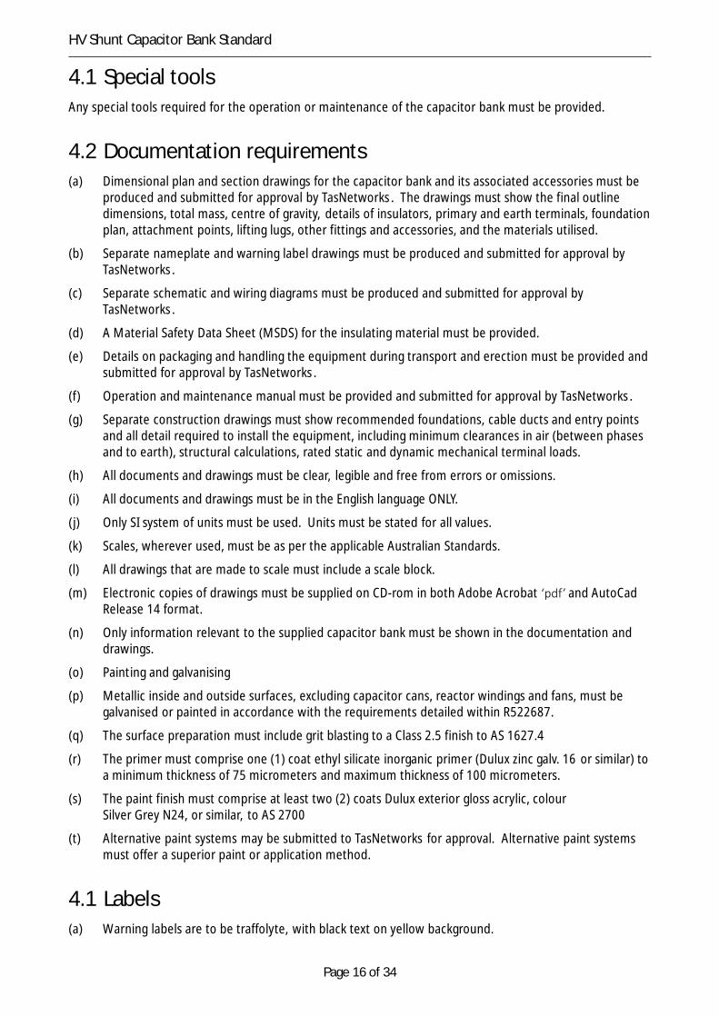
4.1 Special toolsAny special tools required for the operation or maintenance of the capacitor bank must be provided.
4.2 Documentation requirements(a) Dimensional plan and section drawings for the capacitor bank and its associated accessories must be
produced and submitted for approval by TasNetworks . The drawings must show the final outlinedimensions, total mass, centre of gravity, details of insulators, primary and earth terminals, foundationplan, attachment points, lifting lugs, other fittings and accessories, and the materials utilised.
(b) Separate nameplate and warning label drawings must be produced and submitted for approval byTasNetworks .
(c) Separate schematic and wiring diagrams must be produced and submitted for approval byTasNetworks .
(d) A Material Safety Data Sheet (MSDS) for the insulating material must be provided.
(e) Details on packaging and handling the equipment during transport and erection must be provided andsubmitted for approval by TasNetworks .
(f) Operation and maintenance manual must be provided and submitted for approval by TasNetworks .
(g) Separate construction drawings must show recommended foundations, cable ducts and entry pointsand all detail required to install the equipment, including minimum clearances in air (between phasesand to earth), structural calculations, rated static and dynamic mechanical terminal loads.
(h) All documents and drawings must be clear, legible and free from errors or omissions.
(i) All documents and drawings must be in the English language ONLY.
(j) Only SI system of units must be used. Units must be stated for all values.
(k) Scales, wherever used, must be as per the applicable Australian Standards.
(l) All drawings that are made to scale must include a scale block.
(m) Electronic copies of drawings must be supplied on CD-rom in both Adobe Acrobat ‘pdf’ and AutoCadRelease 14 format.
(n) Only information relevant to the supplied capacitor bank must be shown in the documentation anddrawings.
(o) Painting and galvanising
(p) Metallic inside and outside surfaces, excluding capacitor cans, reactor windings and fans, must begalvanised or painted in accordance with the requirements detailed within R522687.
(q) The surface preparation must include grit blasting to a Class 2.5 finish to AS 1627.4
(r) The primer must comprise one (1) coat ethyl silicate inorganic primer (Dulux zinc galv. 16 or similar) toa minimum thickness of 75 micrometers and maximum thickness of 100 micrometers.
(s) The paint finish must comprise at least two (2) coats Dulux exterior gloss acrylic, colourSilver Grey N24, or similar, to AS 2700
(t) Alternative paint systems may be submitted to TasNetworks for approval. Alternative paint systemsmust offer a superior paint or application method.
4.1 Labels(a) Warning labels are to be traffolyte, with black text on yellow background.

Page 17 of 34
HV Shunt Capacitor Bank Standard
(b) Danger labels are to be traffolyte, with black text on red background.
(c) Device number labels are to be traffolyte, with black text on white background.
4.1 Nameplates(a) The capacitor bank, capacitors and reactors must be provided with nameplates that are:
(i) legible and in the English language;
(ii) permanently and indelibly marked;
(iii) securely fixed in position to the body of the equipment or to the enclosure for the capacitorbank;
(iv) weather proof and corrosion-proof;
(v) made of brass, stainless steel or material of equal durability; and
(vi) readable from ground level.
(b) In addition to the requirements of Section 6 of AS 2897 and clause 8.8 of AS/NZS 60076.6, thefollowing information must be included on the equipment nameplate:
(vii) Mass of the device (in kg).
(viii) Rated continuous thermal current (A).
(ix) Purchaser: TasNetworks Networks Pty Ltd.
(x) Purchaser’s contract number: refer to project specifications.
5 Capacitor bank switching, protection and controlequipment
Each capacitor bank shall be connected to a busbar through the following:
(a) A three-pole, withdrawable, vacuum circuit breaker, suitable for capacitive switching and frequentoperation.
(b) Three, single-phase, three-toroid current transformers with one toroid for capacitor bank protectionand one toroid for metering. An additional protection toroid must be included. Where required, thistoroid must be utilised to limit the zone of any existing high-impedance bus-zone protection scheme.
(c) A three-pole earth switch for effective capacitor bank discharge on de-energisation.
(d) Free-standing post insulators for conductor support, where required.
(e) Three, single-phase voltage transformers, or where available, existing busbar voltage transformersmust be utilised for abnormal voltage detection.
(f) Three, single-phase surge diverters.
(g) Three, single-phase capacitive voltage indicators.
(h) Three-phase, high voltage XLPE cable, as required.The following switching arrangements may be utilised and are listed in order of preference. The switchingarrangement will be indicated within the site specific requirements of the project specifications:
• A ‘dedicated’ feeder circuit breaker capable of capacitive switching and frequent operation on theexisting high voltage switchboard using either:
○ a spare feeder circuit breaker; or

Page 18 of 34
HV Shunt Capacitor Bank Standard
○ new switchgear within an extension to the existing high voltage switchboard, where theexisting high voltage switchboard has the capacity for extension within the existingswitchroom dimensions; or
• A ‘shared’ feeder circuit breaker, with new switchgear capable of capacitive switching and frequentoperation within a new building or kiosk.
The Contractor must submit the capacitor bank’s bus connection and switching equipment configuration toTasNetworks for TasNetworks’ review and approval.
5.1 General arrangementThe high voltage switching equipment must be designed to:
(a) conform to TasNetworks’ High Voltage System Standard, R565983;
(b) have a rating of at least 1250 A for the incoming bus riser and 2000 A for busbars;
(c) be fully fault rated and designed and tested to withstand an internal arc due to a short-circuit currentof the same level as the maximum short-time withstand level; and
(d) provide an operating platform within the switchgear compartment, module ‘S’, comprised of at leastthe width of the high voltage switchboard and a minimum distance of 1500 mm in front of the highvoltage switchboard.
5.1 Circuit breakerThe circuit breaker utilised for switching and isolating the high voltage capacitor bank must:
(a) conform to TasNetworks’ High Voltage System Standard, R565983; and
(b) provide the specific parameters listed in Table 3.
Table 3 Parameters for circuit breakers
Sr.No.
Parameter Unit Requirement
Particulars of Circuit Breakers
1 Switching medium - Vacuum
2 Operating cycles of mechanism prior to maintenance (C/O at In) cycles 10 000
3 Service life of mechanism prior to replacement (C/O at In) cycles 30 000
4 Mechanical and electrical service life of vacuum interrupter priorto maintenance and replacement (C/O at In)
cycles 30 000
5.1 Earth switchThe earth switch utilised for earthing the high voltage capacitor bank must:
(a) conform to TasNetworks’ High Voltage System Standard, R565983;
(b) be provided with castell key or solenoid interlocking to permit the operation of any access doors tothe capacitor bank enclosure. Where required, a castell key exchange box must be provided; and
(c) be interlocked with any access doors to the capacitor bank enclosure.
Page 19 of 34
HV Shunt Capacitor Bank Standard
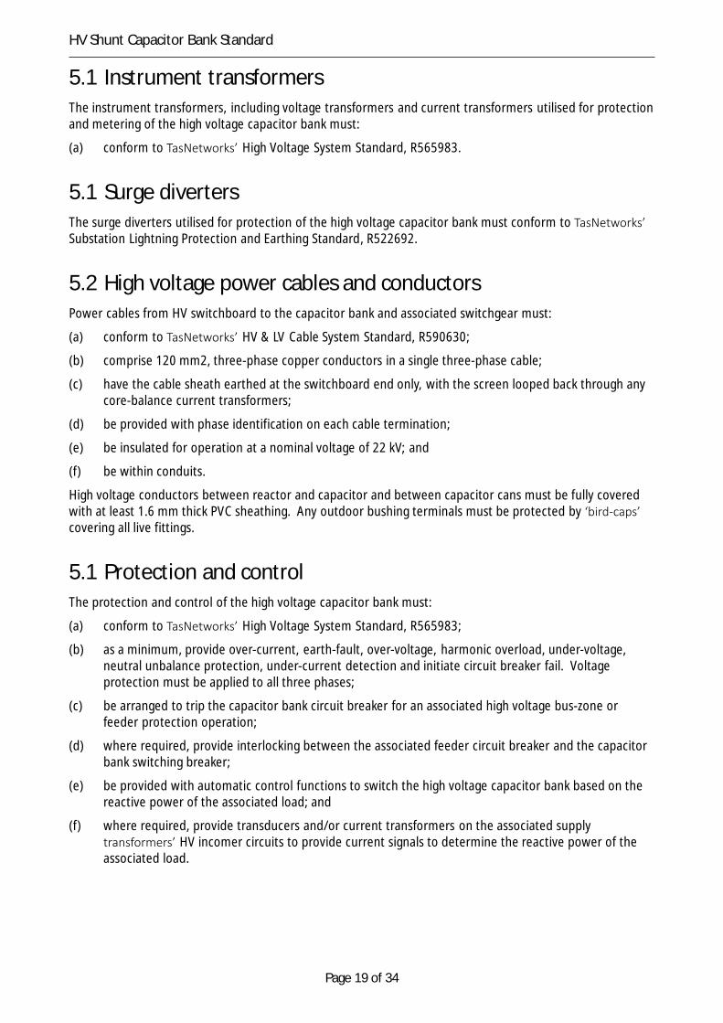
5.1 Instrument transformersThe instrument transformers, including voltage transformers and current transformers utilised for protectionand metering of the high voltage capacitor bank must:
(a) conform to TasNetworks’ High Voltage System Standard, R565983.
5.1 Surge divertersThe surge diverters utilised for protection of the high voltage capacitor bank must conform to TasNetworks’Substation Lightning Protection and Earthing Standard, R522692.
5.2 High voltage power cables and conductorsPower cables from HV switchboard to the capacitor bank and associated switchgear must:
(a) conform to TasNetworks’ HV & LV Cable System Standard, R590630;
(b) comprise 120 mm2, three-phase copper conductors in a single three-phase cable;
(c) have the cable sheath earthed at the switchboard end only, with the screen looped back through anycore-balance current transformers;
(d) be provided with phase identification on each cable termination;
(e) be insulated for operation at a nominal voltage of 22 kV; and
(f) be within conduits.
High voltage conductors between reactor and capacitor and between capacitor cans must be fully coveredwith at least 1.6 mm thick PVC sheathing. Any outdoor bushing terminals must be protected by ‘bird-caps’covering all live fittings.
5.1 Protection and controlThe protection and control of the high voltage capacitor bank must:
(a) conform to TasNetworks’ High Voltage System Standard, R565983;
(b) as a minimum, provide over-current, earth-fault, over-voltage, harmonic overload, under-voltage,neutral unbalance protection, under-current detection and initiate circuit breaker fail. Voltageprotection must be applied to all three phases;
(c) be arranged to trip the capacitor bank circuit breaker for an associated high voltage bus-zone orfeeder protection operation;
(d) where required, provide interlocking between the associated feeder circuit breaker and the capacitorbank switching breaker;
(e) be provided with automatic control functions to switch the high voltage capacitor bank based on thereactive power of the associated load; and
(f) where required, provide transducers and/or current transformers on the associated supplytransformers’ HV incomer circuits to provide current signals to determine the reactive power of theassociated load.
Page 20 of 34
HV Shunt Capacitor Bank Standard
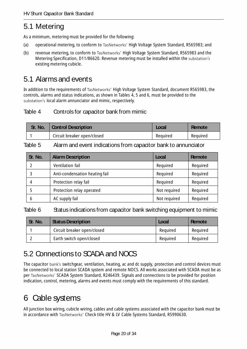
5.1 MeteringAs a minimum, metering must be provided for the following:
(a) operational metering, to conform to TasNetworks’ High Voltage System Standard, R565983; and
(b) revenue metering, to conform to TasNetworks’ High Voltage System Standard, R565983 and theMetering Specification, D11/86620. Revenue metering must be installed within the substation’sexisting metering cubicle.
5.1 Alarms and eventsIn addition to the requirements of TasNetworks’ High Voltage System Standard, document R565983, thecontrols, alarms and status indications, as shown in Tables 4, 5 and 6, must be provided to thesubstation’s local alarm annunciator and mimic, respectively.
Table 4 Controls for capacitor bank from mimic
Sr. No. Control Description Local Remote
1 Circuit breaker open/closed Required Required
Table 5 Alarm and event indications from capacitor bank to annunciator
Sr. No. Alarm Description Local Remote
2 Ventilation fail Required Required
3 Anti-condensation heating fail Required Required
4 Protection relay fail Required Required
5 Protection relay operated Not required Required
6 AC supply fail Not required Required
Table 6 Status indications from capacitor bank switching equipment to mimic
Sr. No. Status Description Local Remote
1 Circuit breaker open/closed Required Required
2 Earth switch open/closed Required Required
5.2 Connections to SCADA and NOCSThe capacitor bank’s switchgear, ventilation, heating, ac and dc supply, protection and control devices mustbe connected to local station SCADA system and remote NOCS. All works associated with SCADA must be asper TasNetworks’ SCADA System Standard, R246439. Signals and connections to be provided for positionindication, control, metering, alarms and events must comply with the requirements of this standard.
6 Cable systemsAll junction box wiring, cubicle wiring, cables and cable systems associated with the capacitor bank must bein accordance with TasNetworks’ Check title HV & LV Cable Systems Standard, R5990630.
Page 21 of 34
HV Shunt Capacitor Bank Standard
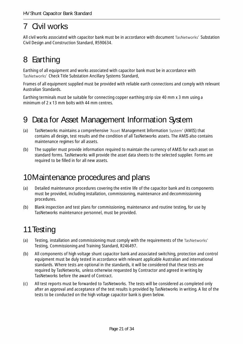
7 Civil worksAll civil works associated with capacitor bank must be in accordance with document TasNetworks’ SubstationCivil Design and Construction Standard, R590634.
8 EarthingEarthing of all equipment and works associated with capacitor bank must be in accordance withTasNetworks’ Check Title Substation Ancillary Systems Standard,
Frames of all equipment supplied must be provided with reliable earth connections and comply with relevantAustralian Standards.
Earthing terminals must be suitable for connecting copper earthing strip size 40 mm x 3 mm using aminimum of 2 x 13 mm bolts with 44 mm centres.
9 Data for Asset Management Information System(a) TasNetworks maintains a comprehensive ‘Asset Management Information System’ (AMIS) that
contains all design, test results and the condition of all TasNetworks assets. The AMIS also containsmaintenance regimes for all assets.
(b) The supplier must provide information required to maintain the currency of AMIS for each asset onstandard forms. TasNetworks will provide the asset data sheets to the selected supplier. Forms arerequired to be filled in for all new assets.
10Maintenance procedures and plans(a) Detailed maintenance procedures covering the entire life of the capacitor bank and its components
must be provided, including installation, commissioning, maintenance and decommissioningprocedures.
(b) Blank inspection and test plans for commissioning, maintenance and routine testing, for use byTasNetworks maintenance personnel, must be provided.
11Testing(a) Testing, installation and commissioning must comply with the requirements of the TasNetworks’
Testing, Commissioning and Training Standard, R246497.
(b) All components of high voltage shunt capacitor bank and associated switching, protection and controlequipment must be duly tested in accordance with relevant applicable Australian and internationalstandards. Where tests are optional in the standards, it will be considered that these tests arerequired by TasNetworks, unless otherwise requested by Contractor and agreed in writing byTasNetworks before the award of Contract.
(c) All test reports must be forwarded to TasNetworks. The tests will be considered as completed onlyafter an approval and acceptance of the test results is provided by TasNetworks in writing. A list of thetests to be conducted on the high voltage capacitor bank is given below.
Page 22 of 34
HV Shunt Capacitor Bank Standard
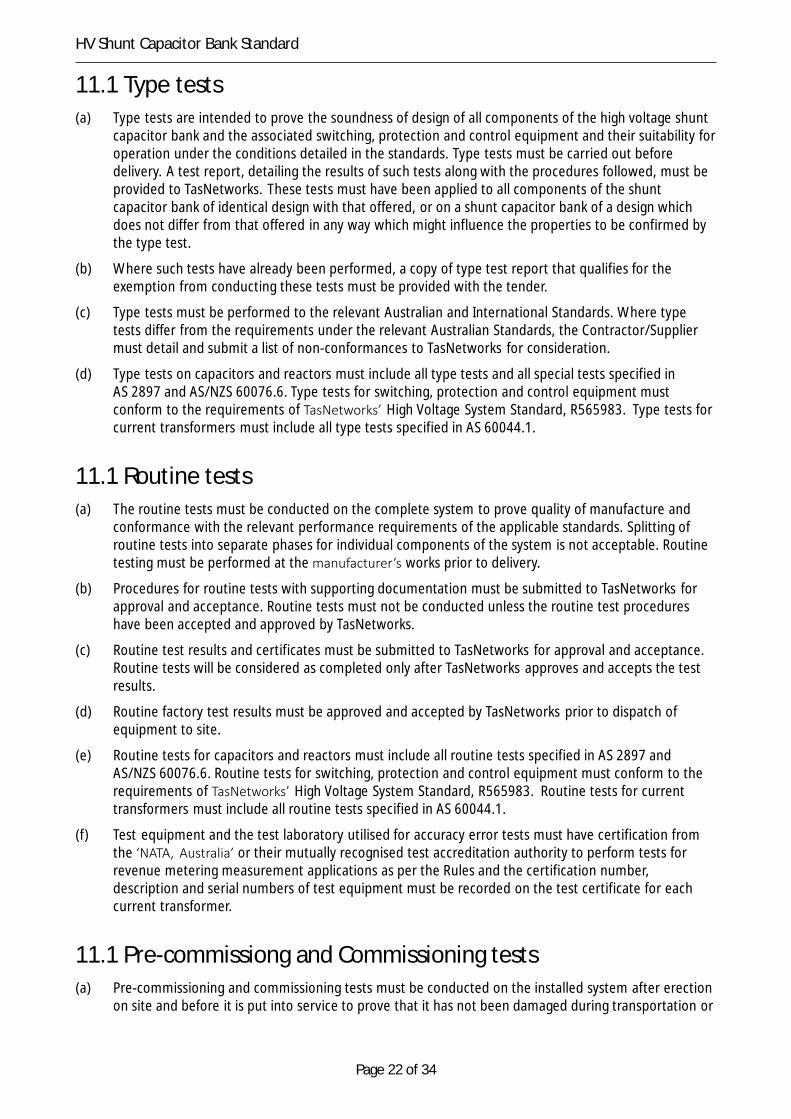
11.1 Type tests(a) Type tests are intended to prove the soundness of design of all components of the high voltage shunt
capacitor bank and the associated switching, protection and control equipment and their suitability foroperation under the conditions detailed in the standards. Type tests must be carried out beforedelivery. A test report, detailing the results of such tests along with the procedures followed, must beprovided to TasNetworks. These tests must have been applied to all components of the shuntcapacitor bank of identical design with that offered, or on a shunt capacitor bank of a design whichdoes not differ from that offered in any way which might influence the properties to be confirmed bythe type test.
(b) Where such tests have already been performed, a copy of type test report that qualifies for theexemption from conducting these tests must be provided with the tender.
(c) Type tests must be performed to the relevant Australian and International Standards. Where typetests differ from the requirements under the relevant Australian Standards, the Contractor/Suppliermust detail and submit a list of non-conformances to TasNetworks for consideration.
(d) Type tests on capacitors and reactors must include all type tests and all special tests specified inAS 2897 and AS/NZS 60076.6. Type tests for switching, protection and control equipment mustconform to the requirements of TasNetworks’ High Voltage System Standard, R565983. Type tests forcurrent transformers must include all type tests specified in AS 60044.1.
11.1 Routine tests(a) The routine tests must be conducted on the complete system to prove quality of manufacture and
conformance with the relevant performance requirements of the applicable standards. Splitting ofroutine tests into separate phases for individual components of the system is not acceptable. Routinetesting must be performed at the manufacturer’s works prior to delivery.
(b) Procedures for routine tests with supporting documentation must be submitted to TasNetworks forapproval and acceptance. Routine tests must not be conducted unless the routine test procedureshave been accepted and approved by TasNetworks.
(c) Routine test results and certificates must be submitted to TasNetworks for approval and acceptance.Routine tests will be considered as completed only after TasNetworks approves and accepts the testresults.
(d) Routine factory test results must be approved and accepted by TasNetworks prior to dispatch ofequipment to site.
(e) Routine tests for capacitors and reactors must include all routine tests specified in AS 2897 andAS/NZS 60076.6. Routine tests for switching, protection and control equipment must conform to therequirements of TasNetworks’ High Voltage System Standard, R565983. Routine tests for currenttransformers must include all routine tests specified in AS 60044.1.
(f) Test equipment and the test laboratory utilised for accuracy error tests must have certification fromthe ‘NATA, Australia’ or their mutually recognised test accreditation authority to perform tests forrevenue metering measurement applications as per the Rules and the certification number,description and serial numbers of test equipment must be recorded on the test certificate for eachcurrent transformer.
11.1 Pre-commissiong and Commissioning tests(a) Pre-commissioning and commissioning tests must be conducted on the installed system after erection
on site and before it is put into service to prove that it has not been damaged during transportation or
Page 23 of 34
HV Shunt Capacitor Bank Standard
erection. The pre-commissioning and commissioning testing procedures must be submitted toTasNetworks for approval.
(b) Power quality tests on the power system must be conducted for at least 1 week prior to the systembeing put into service and for at least 1 week after the system is put into service. Power quality testsmust be performed on all phase voltages, transformer incomer currents and capacitor bank currentsand include waveform recording, measurements to the 13th harmonic, total harmonic distortion,voltage unbalance and flicker.
(c) Electrical tests on the complete capacitor bank and associated power cables must be performed toconform to the requirements of TasNetworks’ High Voltage System Standard, R565983.
(d) Sound pressure tests must be performed on the energised capacitor bank to AS 2374 Part 6, with allventilation in service. Where sound pressure levels are greater than the levels stated in Table 1, noisecontainment measures are to be introduced by the contractor to reduce the noise to an acceptablelevel at the site boundary. This may include, but not limited to, the installation of ducts or theinstallation of noise containment walls.
(e) On-load checks must be carried out on all protection and metering circuits and must also includerecording of phase angles.
(f) Commissioning test reports must be submitted to TasNetworks for approval and records.
12Packaging(a) The supplier is responsible for ensuring that adequate packaging and external signage is provided to
minimize the risk of damage to equipment during delivery and removal from packaging. The packagingmust be suited to the particular methods of delivery and provide protection against damage from allforeseen hazards.
(b) Packaging must be externally labelled for ease of identification of the capacitor bank and itscomponents.
(c) Details of packaging methods must be submitted to TasNetworks for review.
13Information to be provided with tenderRequirements for information to be submitted as part of the tender are outlined in document R579292 HighVoltage Shunt Capacitor Bank Schedule.
Addition requirements for information to be submitted as part of the tender for switching, protection andcontrol equipment are outlined in document R586383 High Voltage Systems Schedule.
14DeliverablesRequirements for project deliverables are outlined in document R579291 High Voltage Shunt Capacitor Bank(Deliverables). Additional requirements for project deliverables for switching, protection and controlequipment are outlined in document R586382 High Voltage Systems (Deliverables).
15Hold pointsThe requirement of documentation is listed in the deliverable schedule in R586382.
The hold points for each capacitor bank are:

Page 24 of 34
HV Shunt Capacitor Bank Standard
(a) "Critical design information documentation" must be submitted four weeks after letter of acceptancefor TasNetworks’ review, comments and approval prior to procurement of equipment;
(b) "Detailed design documentation" must be submitted prior to manufacturing of equipment, forTasNetworks’ review, comments and approval. A face-to-face design review must be held at theearliest opportunity after the electrical design has been finalised and an early draft of the outlinedrawing is available. Information must be provided in good time before the meeting to permit studyof the detailed design aspects.
(c) "Inspection and Test Plan" must be submitted one month prior to "Factory Acceptance Testing (FAT)",for TasNetworks’ review, comments and approval;
(d) Draft “Operations and Maintenance manuals (O&M manuals)” must be provided at least one monthprior to FAT, for TasNetworks’ review, comments and approval;
(e) "Invitation to witness testing" must be submitted prior to any equipment testing, for TasNetworks’arrangements to witness. A minimum of two weeks notice must be given;
(f) Complete updated O&M manuals must be submitted one week prior to FAT for TasNetworks’preparation to attend FAT;
(g) Final training manuals must be provided at least two weeks prior to training, for use of training team;
(h) "FAT" must have been witnessed by TasNetworks and FAT results approved by TasNetworks, prior todispatch of the capacitor bank from the factory;
(i) All non-conformances as identified during FAT or other inspections must have been completed priorto dispatch of the capacitor bank from the factory;
(j) Information required for AMIS pertaining to design information and maintenance regimes must besubmitted to TasNetworks prior to commencing installation;
(k) "Pre-commissioning tests" must have been witnessed by TasNetworks and test results approved byTasNetworks, prior to "commissioning tests";
(l) All non-conformances as identified during pre-commissioning tests must have been completed beforecommencing any commissioning tests;
(m) Results of commissioning tests must have been approved by TasNetworks and relevant testingauthorities as per the requirements of the Rules, prior to commissioning;
(n) "Commissioning tests" must have been witnessed by TasNetworks and test results approved byTasNetworks, prior to "energisation";
(o) All non-conformances as identified during commissioning tests must be completed beforecommencing any energisation;
(p) "Training" must have been completed prior to energisation;
(q) Information for AMIS pertaining to test results must have been submitted to TasNetworks prior toenergisation;
(r) Certificate of conformance with contract specifications, standard specifications, codes and standardswith associated documents, drawings, test results, test reports, test certificates, completed check listsand other documents must be submitted and must have been accepted and approved by TasNetworksprior to energisation;
(s) TasNetworks must have completed the inspection of each asset prior to its energisation; and
(t) All as-built documentation, software licences, O&M manuals, test results and test certificates must besubmitted to TasNetworks and be accepted by TasNetworks prior to practical completion.
Page 25 of 34
HV Shunt Capacitor Bank Standard
Appendix A – Typical Capacitor Bank details for referencepurposes.

Page 26 of 34
HV Shunt Capacitor Bank Standard
Page 27 of 34
HV Shunt Capacitor Bank Standard
Page 28 of 34
HV Shunt Capacitor Bank Standard
Page 29 of 34
HV Shunt Capacitor Bank Standard
Page 30 of 34
HV Shunt Capacitor Bank Standard
Page 31 of 34
HV Shunt Capacitor Bank Standard
Page 32 of 34
HV Shunt Capacitor Bank Standard
Page 33 of 34
HV Shunt Capacitor Bank Standard

Page 34 of 34
HV Shunt Capacitor Bank Standard


