12
0.75kW – 250kW / 1HP – 350HP 200 – 480V Single & 3 Phase Input AC Variable Speed Drive HVAC BUILDING SERVICES Energy efficient control for HVAC systems with BACnet ™ BUILDING SERVICES Cnet

0.75kW – 250kW / 1HP – 350HP200 – 480V Single & 3 Phase Input
AC Variable Speed Drive
HVAC BUILDING SERVICESEnergy efficient control for HVAC systems with BACnet™
BUILDING SERVICES
Cnet

2 www.invertek.co.uk
Shopping Centres
OfficesApartment Buildings
Kitchens
Hotels
Modern building ventilation and air conditioning systems are designed to provide optimum climatic conditions for occupants 365 days per year. As such, they must be able to cope with the heat of a mid-summer day equally as well as a frosty winter morning. Building designers must take account of these extremes and select components and systems capable of providing the required comfort levels under all conditions, meaning that during the majority of the time, systems are operating at less than their full designed capacity.
Optidrive HVAC provides a perfect solution to the needs of designers looking to optimise the performance of fans
and pumps used in HVAC applications, allowing them to operate with maximum efficiency under all conditions. Invertek’s philosophy to provide innovative products with easy to use, energy efficient features ensures that time, cost and energy savings are maximised at all times, resulting in the shortest possible payback period – the time taken to recover the initial product and installation costs through financial savings achieved through installing Optidrive HVAC drives.
For simple installation into your buildings management system all Optidrive HVAC drives are provided with both BACnet and Modbus RTU as standard across the product range.
Energy Efficient HVAC Control
Take Control of Your Environment
AC variable speed drives designed speciifcally for HVAC applications
EnergySa
ve
Offi
nvironment
Offices
EnSav
222222222Cut
SchoolsLaboratories
Conference CentresHospitalsAirports
Instant Power Savings
Power
Flow (%)
Input to Optidrive HVAC
variable speed system
Input to fixed speed system
With variable speed control, Optidrive HVAC immediately reduces power usage compared to fixed speed systems.
Energy Savings CalculatorEstimate your potential energy savings, CO2 emissions and financial savings using our free software.
www.invertek.co.uk/calculator

3
BUILDING SERVICES
Energy efficient control for HVAC systems
Controlling Your HVAC System
Energy OptimisationThe advanced optimisation function intelligently matches energy usage to the fan or pump load to ensure your system operates at maximum efficiency.
Energy MonitoringThe inbuilt energy consumption meters allow energy consumption to be clearly displayed and savings to be calculated.
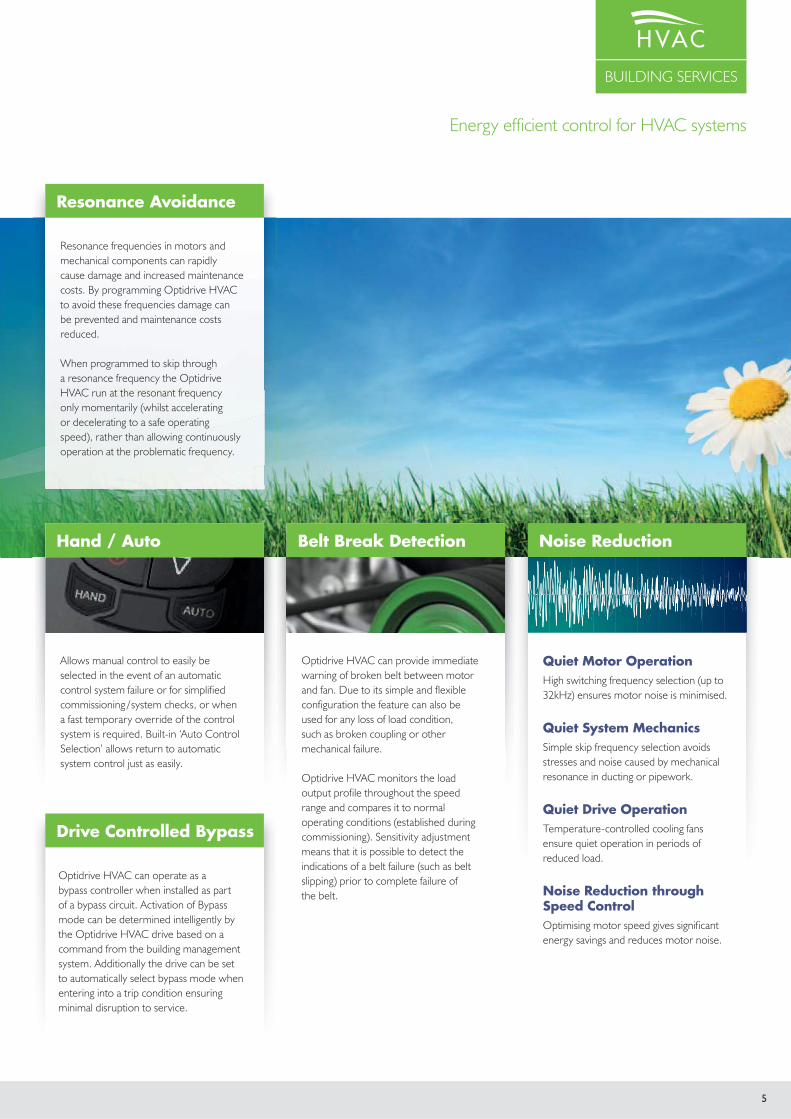
Resonance AvoidanceOptidrive HVAC can be easily configured to avoid frequencies that cause resonance in air handling and pumping systems, preventing unnecessary noise and mechanical damage to motors, ductwork, pipework etc.
In-built Sleep Mode with Auto-boostSleep mode saves energy by detecting when the system is running inefficiently and producing little useful work. Optidrive HVAC can be programmed to enter into a sleep/disabled mode until the demand increases. To help prevent sleep mode oscillation, Optidrive HVAC can automatically initiate a boost cycle to increase pressure on starting or stopping.
Optimising Efficiency
Accurate speed control of fans and pumps provides the most energy efficient control method
Energy optimisation function minimises energy usage in real time under partial load conditions
Sleep & wake functions ensure operation only when required
Advanced on-board features remove the need for peripheral equipment
Intelligent maintenance interval timing allows programmable maintenance reminders, avoiding costly downtime
Automatic load monitoring provides an early warning of potential faults, such as belt failures or blocked filters
Built in keypad and OLED text display provides intuitive operation
Simple parameter structure with carefully selected default values reduce commissioning time
Practical design allows easy access to power and control terminals without specialist tools
Save Energy Save Money Save Time
Optidrive HVAC has a PID controller built in that is fully integrated with both HVAC and energy efficient features and is packaged in a user friendly way to ensure ease of use and fast commissioning. Now in the majority of applications it has become possible to eliminate the need for external controllers.
DUCTVENT
AIRFLOW
OUTLETS
OUTLET
PRESSURETRANSDUCERMOTOR
OUTPUT
© SETPOINT CONTROL
© SYSTEM FEEDBACK

4 www.invertek.co.uk
Setpoint Control
Dedicated to HVAC ApplicationsTake control of your environment
All drives operate as variable speed for maximum energy saving.
Equal run time sharing across each fan / fan bank.
Automatic system reconfiguration in the event of a fan fault.
Continued system operation when drives are individually powered off.
Communication and +24V control voltage shared between drives via a standard RJ45 patch lead.
Independent maintenance indicators for each fan bank.
Any fan bank can be switched to Hand operation at the touch of a button and will automatically rejoin the network when switched back to Auto.
For belt driven fan applications each fan can be set for belt break detection.
Optional mains isolator with lockoff for safe system maintenance.
Drives configured through simple parameter set-up and intelligent drive self configuration.
Multiple Fan Operation
Co-ordinated fan station controlbuilt-in to each Optidrive HVAC as standard allows independent control in multiple fan or fan bank applications
Drive communications
Also ideal for multi-stage / booster set pumping operations.
5
BUILDING SERVICES
Energy efficient control for HVAC systems
Hand / Auto Hand / AutoHand / Auto Hand / Auto
Optidrive HVAC can provide immediate warning of broken belt between motor and fan. Due to its simple and flexible configuration the feature can also be used for any loss of load condition, such as broken coupling or other mechanical failure.
Optidrive HVAC monitors the load output profile throughout the speed range and compares it to normal operating conditions (established during commissioning). Sensitivity adjustment means that it is possible to detect the indications of a belt failure (such as belt slipping) prior to complete failure of the belt.
Hand / Auto
Drive Controlled Bypass
Resonance Avoidance
Belt Break Detection
Quiet Motor OperationHigh switching frequency selection (up to 32kHz) ensures motor noise is minimised.
Quiet System MechanicsSimple skip frequency selection avoids stresses and noise caused by mechanical resonance in ducting or pipework.
Quiet Drive OperationTemperature-controlled cooling fans ensure quiet operation in periods of reduced load.
Noise Reduction through Speed ControlOptimising motor speed gives significant energy savings and reduces motor noise.
Noise Reduction
Allows manual control to easily be selected in the event of an automatic control system failure or for simplified commissioning / system checks, or when a fast temporary override of the control system is required. Built-in ‘Auto Control Selection’ allows return to automatic system control just as easily.
Optidrive HVAC can operate as a bypass controller when installed as part of a bypass circuit. Activation of Bypass mode can be determined intelligently by the Optidrive HVAC drive based on a command from the building management system. Additionally the drive can be set to automatically select bypass mode when entering into a trip condition ensuring minimal disruption to service.
Resonance frequencies in motors and mechanical components can rapidly cause damage and increased maintenance costs. By programming Optidrive HVAC to avoid these frequencies damage can be prevented and maintenance costs reduced.
When programmed to skip through a resonance frequency the Optidrive HVAC run at the resonant frequency only momentarily (whilst accelerating or decelerating to a safe operating speed), rather than allowing continuously operation at the problematic frequency.

6 www.invertek.co.uk
Building Comfort
Dedicated to HVAC ApplicationsTake control of your environment
POSITIVEPRESSURE
INT
ERNA
L SMO
KE SH
AFT
PLANT ROOM
Creating comfortable building environments without high energy costs
Where do the energy savings come from?
Air conditioning can use a huge amount of energy. In some cases it could even double energy consumption, not to mention the resultant increase in a company’s carbon footprint.
Don't produce more airflow than you need!
Typically the air conditioning systems in buildings are designed for maximum occupancy and peak outside ambient. This means that for the majority of time there is large scope for running the systems at reduced speed and significant money to be saved with variable speed drives.
Optidrive HVAC can vary the output of your air conditioning system to meet the varying demands throughout the day.
Stairwell Pressurisation
Ventilation Systems
Ventilation Systems
Fire Override
Smoke & Fume Extraction

7
BUILDING SERVICES
Energy efficient control for HVAC systems
Building Safety Systems
Fire override mode ignores signals and alarms, keeping the Optidrive HVAC operating for as long as possible.
This feature is crucial for ensuring smoke extraction from buildings in the event of a fire.
Selectable logic means that the Optidrive HVAC can be easily configured to the signal produced by your fire management system.
With an independently set speed for fire mode operation, selectable as either forward or reverse direction, the Optidrive HVAC has the flexibility to match the needs of your fire control system.
Fire mode operation is indicated clearly on the drive display during periods of fire mode operation.
Drive output logic can easily be configurable for indicating to external drives that fire mode is active.
Internal clocks and timers monitoring operation in fire mode, giving clear information on usage.
Stairwell (escape route) pressurisation systems are being extensively employed in large buildings and complexes to help ensure the safe evacuation of occupants during a fire. Variable speed drives are playing an increasing role in maintaining pressures (of approximately 50 Pa) within these critical areas. Here Optidrive HVAC is used to provide a smoke free escape by accurately maintaining the air pressure along that route.
Pressures must be maintained at a high enough level that a door opened between the fire floor and the escape route does not result in smoke entering the escape route. Equally, as doors and vents are opened along the escape route allowing air to escape the Optidrive and stairwell pressurisation system must increase output so that the required pressure is accurately maintained.
Chiller Water PumpsVariable Speed Control for PumpsOptidrive HVAC provides the ideal pump control solution for chiller, circulation and cooling pumps.
Dual Setpoint Control maximises energy savings by allowing pumps to be switched back to lower setpoints during quieter, low demand periods whilst maintaining full operation when required.
Advanced Multi-pump Management allows pumps which operate in typical configurations such as Duty / Standby or Duty / Assist / Standby to be simply connected together using RJ45 patch cables and commissioned as a single pump set, saving installation and commissioning time and providing fully automatic duty changeover operation.
Many buildings now incorporate dedicated smoke management and extraction systems designed to safety exact smoke in the event of a fire, these systems are designed to localise and extract smoke such that the rest of the building remains smoke free and can be evacuated safely. Here the Optidrive's Fire Mode function is critical in maintaining continued operation of the smoke extraction system for the longest permissible period.
For applications such as underground car parks the fans providing fresh air intake are often reversed in the event of a fire to provide smoke extraction. Optidrive HVAC is easily configured for bi-directional fire mode operation.
Stairwell Pressurisation
Smoke & Fume Extraction
Fire Override
8 www.invertek.co.uk
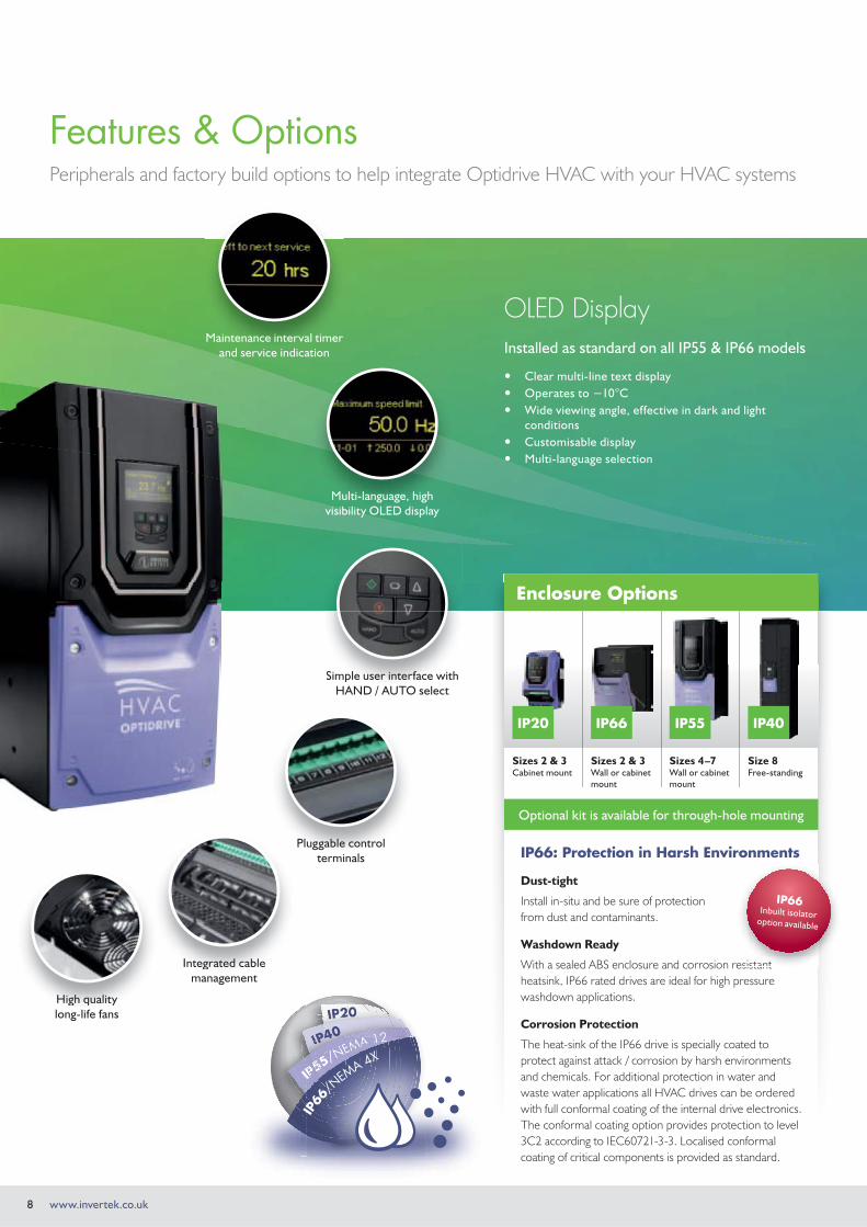
Features & OptionsPeripherals and factory build options to help integrate Optidrive HVAC with your HVAC systems
OLED DisplayInstalled as standard on all IP55 & IP66 models
Clear multi-line text display Operates to −10°C Wide viewing angle, effective in dark and light
conditions Customisable display Multi-language selection
Maintenance interval timer and service indication
Multi-language, high visibility OLED display
Simple user interface with HAND / AUTO select
Pluggable control terminals
Integrated cablemanagement
High quality long-life fans
IIIIII
IP55/NEMA IIIIIIIII
IIPPPPPPPP5555555555555//NEEEMMMMMMMMMAAAAAAAAAA
IP66
/NEM
A 4X
Integrated cable
High quality
Simple user interface with
Enclosure Options
Sizes 2 & 3Cabinet mount
Sizes 2 & 3Wall or cabinet mount
Sizes 4–7Wall or cabinet mount
Size 8Free-standing
IP66: Protection in Harsh Environments
Dust-tight
Install in-situ and be sure of protection from dust and contaminants.
Washdown Ready
With a sealed ABS enclosure and corrosion resistant heatsink, IP66 rated drives are ideal for high pressure washdown applications.
Corrosion Protection
The heat-sink of the IP66 drive is specially coated to protect against attack / corrosion by harsh environments and chemicals. For additional protection in water and waste water applications all HVAC drives can be ordered with full conformal coating of the internal drive electronics. The conformal coating option provides protection to level 3C2 according to IEC60721-3-3. Localised conformal coating of critical components is provided as standard.
esistant
IP66Inbuilt isolator
option available
IP40IP55IP20 IP66
Optional kit is available for through-hole mounting

9
BUILDING SERVICES
Energy efficient control for HVAC systems
Compatible with Windows XP, Windows Vista & Windows 7
Plug-in Modules Mains IsolatorOptipad
Optistick
Rapid Commissioning Tool
Plug-in or wirelessly copy parameter sets between drives.
www.invertek.co.uk
Powerful PC SoftwareDrive commissioning and parameter backup
Real-time parameter editing Drive network communication Parameter upload, download and storage Simple PLC function programming
Remote Keypad & OLED Display
IP55 panel mount operator interface.
Clear multi-line text display
Multiple language select
Customisable displays
Mains Isolator Option
Lockable mains isolator option. Can be used with sizes 4-8.
Extend functionality and communication options
Expansion Modules Extended I/O
(3 x Digital In, 1 x Relay Out)
Cascade Control (extended Relay) (3 x Relay Outputs)
Fieldbus Interfaces BACnet/IP
EtherNet/IP
DeviceNet
Profibus
provided as standard
10 www.invertek.co.uk
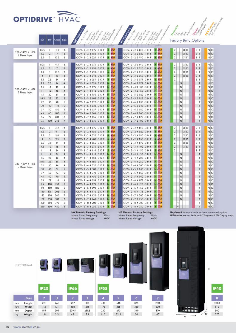
kW HP Amps Size
200 – 240V ± 10%1 Phase Input
0.75 1 4.3 2 ODV - 2 - 2 2 075 - 1 K F 1 #-## ODV - 2 - 2 2 010 - 1 H F 1 #-## 2 X D S T N C1.5 2 7 2 ODV - 2 - 2 2 150 - 1 K F 1 #-## ODV - 2 - 2 2 020 - 1 H F 1 #-## 2 X D S T N C2.2 3 10.5 2 ODV - 2 - 2 2 220 - 1 K F 1 #-## ODV - 2 - 2 2 030 - 1 H F 1 #-## 2 X D S T N C
200 – 240V ± 10%3 Phase Input
0.75 1 4.3 2 ODV - 2 - 2 2 075 - 3 K F 1 #-## ODV - 2 - 2 2 010 - 3 H F 1 #-## 2 X D S T N C1.5 2 7 2 ODV - 2 - 2 2 150 - 3 K F 1 #-## ODV - 2 - 2 2 020 - 3 H F 1 #-## 2 X D S T N C2.2 3 10.5 2 ODV - 2 - 2 2 220 - 3 K F 1 #-## ODV - 2 - 2 2 030 - 3 H F 1 #-## 2 X D S T N C4 5 18 3 ODV - 2 - 3 2 040 - 3 K F 1 #-## ODV - 2 - 3 2 050 - 3 H F 1 #-## 2 X D S T N C
5.5 7.5 24 3 ODV - 2 - 3 2 055 - 3 K F 1 2 -## ODV - 2 - 3 2 075 - 3 H F 1 2 -## 2 S T N C5.5 7.5 24 4 ODV - 2 - 4 2 055 - 3 K F 1 N- T # ODV - 2 - 4 2 075 - 3 H F 1 N- T # N T N C7.5 10 30 4 ODV - 2 - 4 2 075 - 3 K F 1 N- T # ODV - 2 - 4 2 100 - 3 H F 1 N- T # N T N C11 15 46 4 ODV - 2 - 4 2 110 - 3 K F 1 N- T # ODV - 2 - 4 2 150 - 3 H F 1 N- T # N T N C15 20 61 5 ODV - 2 - 5 2 150 - 3 K F 1 N- T # ODV - 2 - 5 2 020 - 3 H F 1 N- T # N T N C
18.5 25 72 5 ODV - 2 - 5 2 185 - 3 K F 1 N- T # ODV - 2 - 5 2 025 - 3 H F 1 N- T # N T N C22 30 90 6 ODV - 2 - 6 2 022 - 3 K F 1 N- T # ODV - 2 - 6 2 030 - 3 H F 1 N- T # N T N C30 40 110 6 ODV - 2 - 6 2 030 - 3 K F 1 N- T # ODV - 2 - 6 2 040 - 3 H F 1 N- T # N T N C37 50 150 6 ODV - 2 - 6 2 037 - 3 K F 1 N- T # ODV - 2 - 6 2 050 - 3 H F 1 N- T # N T N C45 60 180 6 ODV - 2 - 6 2 045 - 3 K F 1 N- T # ODV - 2 - 6 2 060 - 3 H F 1 N- T # N T N C55 75 202 7 ODV - 2 - 7 2 055 - 3 K F 1 N- T # ODV - 2 - 7 2 075 - 3 H F 1 N- T # N T N C75 100 248 7 ODV - 2 - 7 2 075 - 3 K F 1 N- T # ODV - 2 - 7 2 100 - 3 H F 1 N- T # N T N C
380 – 480V ± 10%3 Phase Input
0.75 1 2.2 2 ODV - 2 - 2 4 075 - 3 K F 1 #-## ODV - 2 - 2 4 010 - 3 H F 1 #-## 2 X D S T N C1.5 2 4.1 2 ODV - 2 - 2 4 150 - 3 K F 1 #-## ODV - 2 - 2 4 020 - 3 H F 1 #-## 2 X D S T N C2.2 3 5.8 2 ODV - 2 - 2 4 220 - 3 K F 1 #-## ODV - 2 - 2 4 030 - 3 H F 1 #-## 2 X D S T N C4 5 9.5 2 ODV - 2 - 2 4 400 - 3 K F 1 #-## ODV - 2 - 2 4 050 - 3 H F 1 #-## 2 X D S T N C
5.5 7.5 14 3 ODV - 2 - 3 4 055 - 3 K F 1 #-## ODV - 2 - 3 4 075 - 3 H F 1 #-## 2 X D S T N C7.5 10 18 3 ODV - 2 - 3 4 075 - 3 K F 1 #-## ODV - 2 - 3 4 100 - 3 H F 1 #-## 2 X D S T N C11 15 24 3 ODV - 2 - 3 4 110 - 3 K F 1 2 -## ODV - 2 - 3 4 150 - 3 H F 1 2 -## 2 S T N C11 15 24 4 ODV - 2 - 4 4 110 3 K F 1 N- T # ODV - 2 - 4 4 150 - 3 H F 1 N- T # N T N C15 20 30 4 ODV - 2 - 4 4 150 - 3 K F 1 N- T # ODV - 2 - 4 4 200 - 3 H F 1 N- T # N T N C
18.5 25 39 4 ODV - 2 - 4 4 185 - 3 K F 1 N- T # ODV - 2 - 4 4 250 - 3 H F 1 N- T # N T N C22 30 46 4 ODV - 2 - 4 4 220 - 3 K F 1 N- T # ODV - 2 - 4 4 300 - 3 H F 1 N- T # N T N C30 40 61 5 ODV - 2 - 5 4 300 - 3 K F 1 N- T # ODV - 2 - 5 4 040 - 3 H F 1 N- T # N T N C37 50 72 5 ODV - 2 - 5 4 370 - 3 K F 1 N- T # ODV - 2 - 5 4 050 - 3 H F 1 N- T # N T N C45 60 90 5 ODV - 2 - 5 4 450 - 3 K F 1 N- T # ODV - 2 - 5 4 060 - 3 H F 1 N- T # N T N C55 75 110 6 ODV - 2 - 6 4 055 - 3 K F 1 N- T # ODV - 2 - 6 4 075 - 3 H F 1 N- T # N T N C75 120 150 6 ODV - 2 - 6 4 075 - 3 K F 1 N- T # ODV - 2 - 6 4 120 - 3 H F 1 N- T # N T N C90 150 180 6 ODV - 2 - 6 4 090 - 3 K F 1 N- T # ODV - 2 - 6 4 150 - 3 H F 1 N- T # N T N C
110 175 202 6 ODV - 2 - 6 4 110 - 3 K F 1 N- T # ODV - 2 - 6 4 175 - 3 H F 1 N- T # N T N C132 200 240 7 ODV - 2 - 7 4 132 - 3 K F 1 N- T # ODV - 2 - 7 4 200 - 3 H F 1 N- T # N T N C160 250 302 7 ODV - 2 - 7 4 160 - 3 K F 1 N- T # ODV - 2 - 7 4 250 - 3 H F 1 N- T # N T N C200 300 370 8 ODV - 2 - 8 4 200 - 3 K F 1 4 - T # ODV - 2 - 8 4 300 - 3 H F 1 4 - T # 4 T N C250 350 450 8 ODV - 2 - 8 4 250 - 3 K F 1 4 - T # ODV - 2 - 8 4 350 - 3 H F 1 4 - T # 4 T N C
kW Models: Factory SettingsMotor Rated Frequency: 50HzMotor Rated Voltage: 400V
HP Models: Factory SettingsMotor Rated Frequency: 60HzMotor Rated Voltage: 460V
IP20
IP40
IP55
IP66
IP66
with
Isol
ator
7 Se
gmen
t LED
Disp
lay
OLE
D D
isplay
Full C
onfo
rmal
Coa
ting
Stan
dard
Coa
ting
Encl
osur
e
Dis
play
PCB
Coa
ting
Factory Build Options
Replace # in model code with colour-coded optionIP20 units are available with 7 Segment LED Display only
Fact
ory B
uild
Opt
ions
Prod
uct R
ange
kW M
odel
Cod
e
Gen
erat
ion
EMC
Filte
r
Supp
ly Vo
ltage
Fram
e Siz
ePo
wer
Rat
ing
Inpu
t Pha
ses
Pow
er T
ype
Brak
e Tr
ansis
tor
Fact
ory B
uild
Opt
ions
Prod
uct R
ange
HP
Mod
el C
ode
Gen
erat
ion
EMC
Filte
r
Supp
ly Vo
ltage
Fram
e Siz
ePo
wer
Rat
ing
Inpu
t Pha
ses
Pow
er T
ype
Brak
e Tr
ansis
tor
Sizemm Heightmm Widthmm Depthkg Weight
NOT TO SCALE
WD
H
2 3221 261112 131185 2051.8 3.5
2 3257 310188 211
239.5 251.54.8 7.3
4 5 6 7440 540 865 1280173 235 330 330230 270 340 37011.5 22.5 50 80
82000516500270
IP55 IP40IP20 IP66
11
BUILDING SERVICES
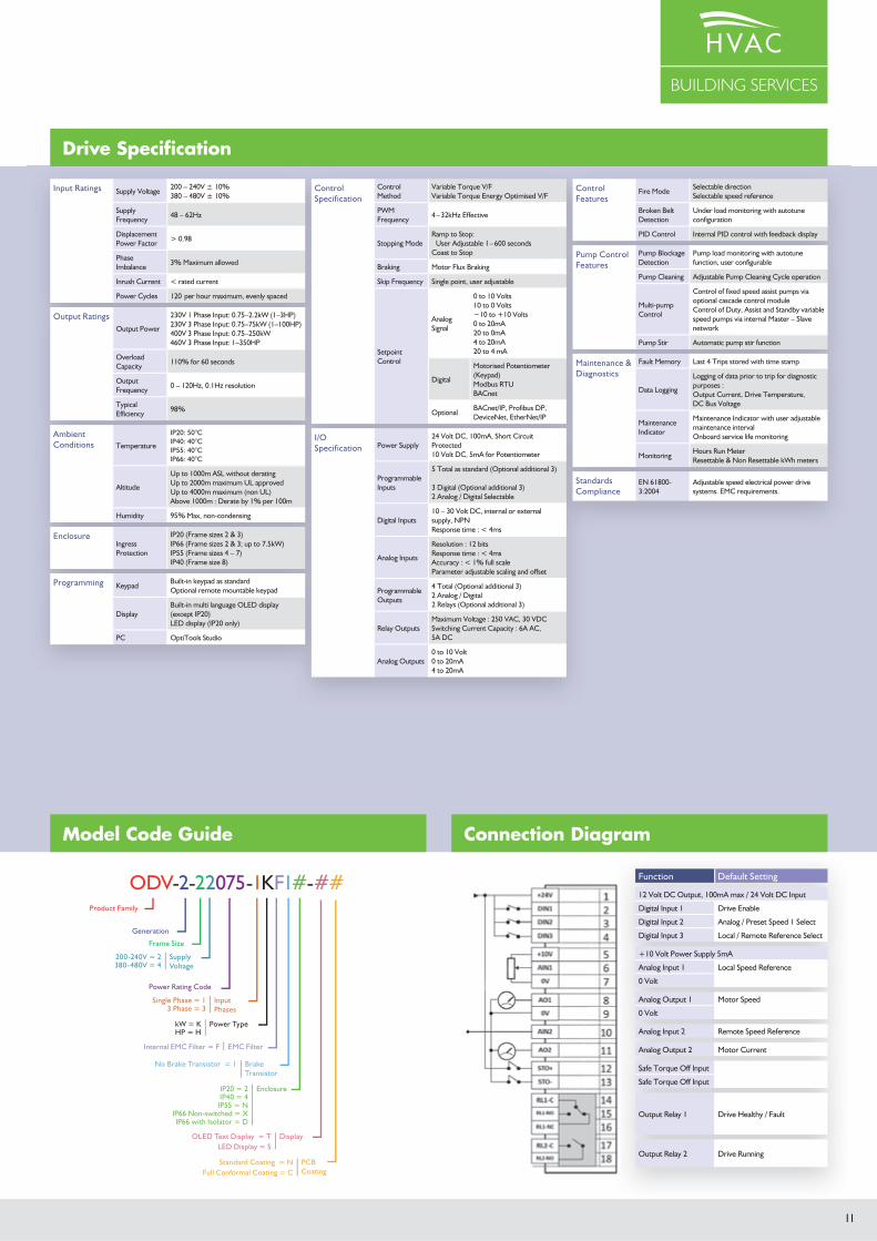
Connection Diagram
Function Default Setting
12 Volt DC Output, 100mA max / 24 Volt DC Input
Digital Input 1 Drive Enable
Digital Input 2 Analog / Preset Speed 1 Select
Digital Input 3 Local / Remote Reference Select
+10 Volt Power Supply 5mA
Analog Input 1 Local Speed Reference
0 Volt
Analog Output 1 Motor Speed
0 Volt
Analog Input 2 Remote Speed Reference
Analog Output 2 Motor Current
Safe Torque Off Input
Safe Torque Off Input
Output Relay 1 Drive Healthy / Fault
Output Relay 2 Drive Running
Input Ratings Supply Voltage200 – 240V ± 10%380 – 480V ± 10%
Supply Frequency
48 – 62Hz
Displacement Power Factor
> 0.98
Phase Imbalance
3% Maximum allowed
Inrush Current < rated current
Power Cycles 120 per hour maximum, evenly spaced
Output RatingsOutput Power
230V 1 Phase Input: 0.75–2.2kW (1–3HP)230V 3 Phase Input: 0.75–75kW (1–100HP)400V 3 Phase Input: 0.75–250kW460V 3 Phase Input: 1–350HP
Overload Capacity
110% for 60 seconds
Output Frequency
0 – 120Hz, 0.1Hz resolution
Typical Efficiency
98%
Ambient Conditions Temperature
IP20: 50°C IP40: 40°C IP55: 40°C IP66: 40°C
Altitude
Up to 1000m ASL without deratingUp to 2000m maximum UL approvedUp to 4000m maximum (non UL)Above 1000m : Derate by 1% per 100m
Humidity 95% Max, non-condensing
EnclosureIngress Protection
IP20 (Frame sizes 2 & 3)IP66 (Frame sizes 2 & 3; up to 7.5kW)IP55 (Frame sizes 4 – 7)IP40 (Frame size 8)
Programming KeypadBuilt-in keypad as standardOptional remote mountable keypad
DisplayBuilt-in multi language OLED display (except IP20)LED display (IP20 only)
PC OptiTools Studio
Control Specification
Control Method
Variable Torque V/FVariable Torque Energy Optimised V/F
PWM Frequency
4 – 32kHz Effective
Stopping ModeRamp to Stop:
User Adjustable 1 – 600 secondsCoast to Stop
Braking Motor Flux Braking
Skip Frequency Single point, user adjustable
Setpoint Control
Analog Signal
0 to 10 Volts10 to 0 Volts−10 to +10 Volts0 to 20mA20 to 0mA4 to 20mA20 to 4 mA
Digital
Motorised Potentiometer (Keypad)Modbus RTUBACnet
OptionalBACnet/IP, Profibus DP, DeviceNet, EtherNet/IP
I/O Specification Power Supply
24 Volt DC, 100mA, Short Circuit Protected 10 Volt DC, 5mA for Potentiometer
Programmable Inputs
5 Total as standard (Optional additional 3)
3 Digital (Optional additional 3) 2 Analog / Digital Selectable
Digital Inputs10 – 30 Volt DC, internal or external supply, NPNResponse time : < 4ms
Analog Inputs
Resolution : 12 bitsResponse time : < 4ms Accuracy : < 1% full scale Parameter adjustable scaling and offset
Programmable Outputs
4 Total (Optional additional 3)2 Analog / Digital2 Relays (Optional additional 3)
Relay OutputsMaximum Voltage : 250 VAC, 30 VDCSwitching Current Capacity : 6A AC, 5A DC
Analog Outputs0 to 10 Volt0 to 20mA4 to 20mA
Control Features
Fire ModeSelectable directionSelectable speed reference
Broken Belt Detection
Under load monitoring with autotune configuration
PID Control Internal PID control with feedback display
Pump Control Features
Pump Blockage Detection
Pump load monitoring with autotune function, user configurable
Pump Cleaning Adjustable Pump Cleaning Cycle operation
Multi-pump Control
Control of fixed speed assist pumps via optional cascade control moduleControl of Duty, Assist and Standby variable speed pumps via internal Master – Slave network
Pump Stir Automatic pump stir function
Maintenance & Diagnostics
Fault Memory Last 4 Trips stored with time stamp
Data Logging
Logging of data prior to trip for diagnostic purposes :Output Current, Drive Temperature, DC Bus Voltage
Maintenance Indicator
Maintenance Indicator with user adjustable maintenance intervalOnboard service life monitoring
MonitoringHours Run MeterResettable & Non Resettable kWh meters
Standards Compliance
EN 61800-3:2004
Adjustable speed electrical power drive systems. EMC requirements.
Model Code Guide
ODV-2-22075-1KF1#-##Product Family
Generation
Frame Size
Power Rating Code
200-240V = 2 Supply Voltage380-480V = 4
Single Phase = 1 Input Phases3 Phase = 3
Internal EMC Filter = F EMC Filter
No Brake Transistor = 1 Brake Transistor
OLED Text Display = T DisplayLED Display = S
Standard Coating = N PCB CoatingFull Conformal Coating = C
kW = K Power TypeHP = H
IP20 = 2 EnclosureIP40 = 4IP55 = N
IP66 Non-switched = XIP66 with Isolator = D
Drive Specification