31
HVAC Fundamentals

HVAC Fundamentals

• Be familiar with Basic HVAC terminology
• Understand the fundamentals of the
refrigeration cycle
• Know the four major components of an HVAC
system and be able to explain each function
• Be knowledgeable about low voltage controls
When you have completed this
section, you will:

When you have completed this
section, you will:
• Be aware of workplace safety measures
while servicing a system
• Know how to use electrical test equipment
• Have practiced wiring controls and
troubleshooting
• Have practiced charging a system

Air Conditioning Theory:
Principle #1:
• Cold is defined as “the absence of heat”. Everything
above absolute Zero is a measurement of _______
Principle #2:
• Heat is ever ready to flow to anything, which contains
____________.
Principle #3:
• Anytime a liquids change to a gas vapor, it must give
up its heat and the heat is carried off in the
____________.
HEAT
Less Heat
Vapor

4 Major Components
of an A/C System
• Compressor: “compresses” or squeezes low temperature/low
pressure vapor in order to raise it to a higher temp and pressure.
• Condenser: The condenser is a device that __________ heat
from the system.
• Evaporator: The evaporator is a device for the __________ of
heat into the system.
• Metering Device: The metering device controls the______ of
refrigerant into the evaporator.
Expels
Absorption
Flow

Basic Cooling Cycle
Compressor Fan MotorCoil
Normally, a refrigerant picks up heat by evaporating and
then gives up heat by condensing.
Two important things to remember about Freon refrigerants are:
1. Refrigerants boil at a very low temperature.
2. There is a direct relationship between the temperature of a
refrigerant and the pressure of a refrigerant.
The condensing unit (located outdoors)
contains three basic components. They are
the , , and
the .

Functions of the 4 Major
Components
The evaporator is the
cooling component of
the system. In the
evaporator, pressure
is reduced and the
liquid boils to a gas at
low temperature as it
absorbs heat from the
substances
surrounding the coil
such as conditioned
space.
The metering device
is located before the
evaporator coil. It
may be a cap tube,
expansion valve, or a
piston. It meters the
proper amount of
liquid to the coil and
maintains a liquid
seal between the high
and low side of the
system.
The condenser is the
component in which
the heat absorbed in
the evaporator is
transferred to the
atmosphere through
the condenser-
cooling medium.
Typically, water or
air
•The compressor is
the workhorse of the
system.
• It draws heat-laden
gas from the
evaporator at low
temp/low pressure
and compresses this
gas, raising its temp/
pressure to the point
at which the gas will
condense
EvaporatorMetering deviceCondenserCompressor

Summary of the Cycle
1 2
3
4
5
6
Flow
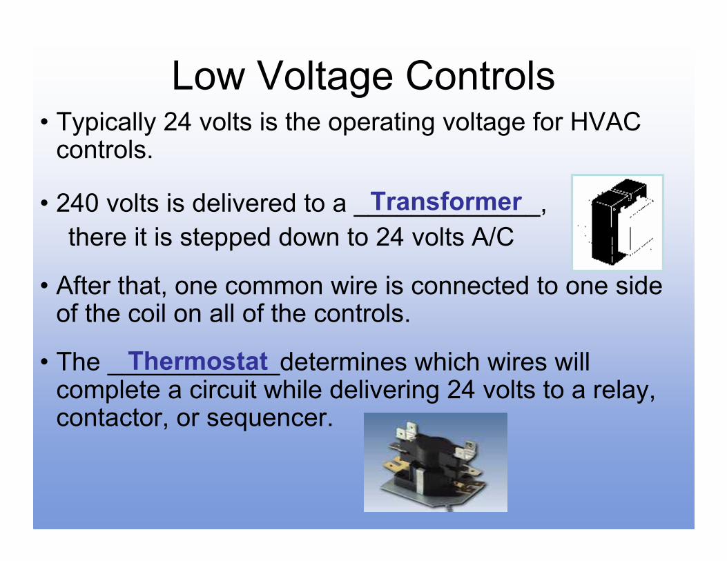
Low Voltage Controls• Typically 24 volts is the operating voltage for HVAC controls.
• 240 volts is delivered to a _____________,
there it is stepped down to 24 volts A/C
• After that, one common wire is connected to one side of the coil on all of the controls.
• The ____________determines which wires will complete a circuit while delivering 24 volts to a relay, contactor, or sequencer.
Transformer
Thermostat

Transformers

Transformers• A transformer produces an electrical
• current through electromagnetic
_______________
• A step-down transformer has more turns of
wire on the __________ and less on the
__________ coil
Induction
PrimarySecondary

Transformers
• A transformer can be diagnosed by checking for
____________and/or ____________
• In a good transformer there should be continuity
between ___________wires on each coil.
• There is ___________ between the primary coil and
the secondary coil.
• If there is no continuity between any wires on the
same coil the transformer is __________.
Voltage Continuity
All
No Continuity
Bad

Thermostats
The simplest way to test a thermostat is to __________
R to Y will energize the _____________________
R to G will energize the _____________________
R to W will energize the _____________________
use a Jumper
Cooling Cycle
Evaporator Fan Motor
Heat Cycle

Thermostats
• If ________ is present and the jumper does not turn on
the air handler or condenser it is time to troubleshoot
the air handler or condenser to determine the problem.
• If a thermostat works with a jumper wire and does not
work without the jumper the thermostat is bad.
24 Volts

• The purpose of a relay is to control a , or
.
• A relay is designed for starting applications.
• The simplest way to check a relay is to listen for a click and then
.
• If no click, check to see if is present to activate the coil.
• It is not uncommon for a relay contact to stick due to .
Relays
SPST NO
SPST NC DPST NO
Switch Motor
Valve
Light Duty
24 Volts
24 V
Overload

Contactors
• A contactor is a large version of a relay designed for a
heavier duty.
• Since a motor in start mode draws up to
more current than while in run mode a contactor is
used.
• Typically a or a
is used in residential HVAC systems.
4 Times
Single Pole Double Pole

Contactors
• A simple way to test a contactor is to push the
contacts together or check for voltage
when the contacts are pulled in
• Why is it important to be certain that a replacement
contactor has the same amperage rating?
• It is not uncommon to find ants covering the contacts
Check for
continuity
Or check if 24
volts is present
High Voltage
Prevent Fire/ Damage/ Overload

Manifold Gauges
• Gauges measure input pressure, output pressure, and
the related temperature.
• A set of gauges will what is taking place
within the field system.
• Without a set of gauges one may only guess what is
taking place in the sealed system.
Confirm

Manifold Gauges
• Compound gauge: Blue - This is on the
side of the system!
• High pressure gauge: Red - This is on the
side of the system and is used to measure pressure
per square inch.
• The service port is to add or remove refrigerant and
.
• The manifold has three ports compound, pressure, and
service.
Low
High
Pull a Vacuum

Temperature and Pressure
What Psi.
is at 32
degrees?90/90 rule
of 30 Over

Troubleshooting
• Example one: Compound gauge reads 80 psig
and the pressure gauge reads 130 psig.
• Example two: Very high pressure one the high
side and low pressure on the low side.
• Example three: Low pressure on the high side
and low pressure to a vacuum on the low side.
Washout Bad - Compressor
Restriction – Cap Tube
Low Refrigerant Charge

Troubleshooting
• Example four: Compound gauge rises steadily and then falls off rapidly. This continues through several system cycles.
• Example five: A near normal low pressure and an unusually high head pressure.
• If a gauge is out if adjustment or does not measure well, replace the gauge. You’ll know when your gauges are faulty when
Dirty Drier or Evaporator Coil
Dirty Condenser Coil
Disconnected there is a reading
Cannot be calibrated to zero

Proper Charging Procedures
1. Always purge lines - To prevent moisture from entering the system.
2. Charge with vapor only - Do not turn the tank over. It will “slug” the compressor (fill it with liquid) and ruin it.
3. Charge on vapor side only - Using the compound gauge’s service port.
4. Charge unit only while it is running - Because the suction pressure will be low enough to allow refrigerant to enter the system. If it is NOT running you cannot know if it has a low charge as the pressure is equalized.

Proper Charging Procedures
5. To avoid freezing condensate water - Always attempt
to charge to a desired evaporator temperature (36° or
above) regardless of temperature outside.
6. A desirable difference in temperature is 15-20° F -
Take the time to explain to the resident that the
maximum differential is 20° to the ambient temperature
outside.

Review Questions
1. What is the definition of law two?
Heat is always ready to transfer
something that has less heat
2. What are the four major components of
an A/C system?
Compressor, Condenser, Metering
Device, and Evaporator

Review Questions
3. In which component of the A/C system is
heat absorbed?
Evaporator
4. What is the function of the thermostat?
To complete or interrupt a control
circuit
5. What units of measure are used for a
vacuum?
Inches of Mercury hg

Wiring a Transformer
Blue
24 volts A/C Secondary Winding
Yellow
Orange 240 Volts
Red 208 Volts
Primary
Winding
Black 120 Volts
White Common
•Blue and Yellow = 24 volts
•Orange And White = 24o volts
•Red and Black = 208 volts
•Black and White = 120 volts

Wiring a Thermostat
50 55 60 65 70 75 80 85 90
Heat
Off
Cool
Fan
Off
Auto
Red
Green
White
Yellow
50 55 60 65 70 75 80 85 90 95
What does each
color control?
•Red = 24 Volts
•Green = Indoor Fan
•White = Heat
•Yellow = Cooling

Wiring a Relay
Normally Open
Contact
5 3 1
Normally Closed
Contact
4 2 6
A/C Connects to the ____ Contact with terminal numbers ______
Heat Connects to the ____ Contact with terminal numbers _____
A/C should be on _____ speed Heat should be on ______speed
NO 3 & 4
NC 1 & 2
High Low

Wiring a Compressor
24V
Herm Com Fan 35 uf 5 uf
35/5 uf Dual capacitor
L 1
L 2
Common
Run Start
Compressor
24 Volts
240
Volts
A/C
Contactor

Wiring a Hard Start Capacitor
Super
Boost
For ½ to 5 hp
Compressors
Herm & Common
Temporary extra Start Power
4 Times
To which terminals do the leads connect?
What is the purpose of this component?
A super boost provides
more than the amount of power of a
regular capacitor.


