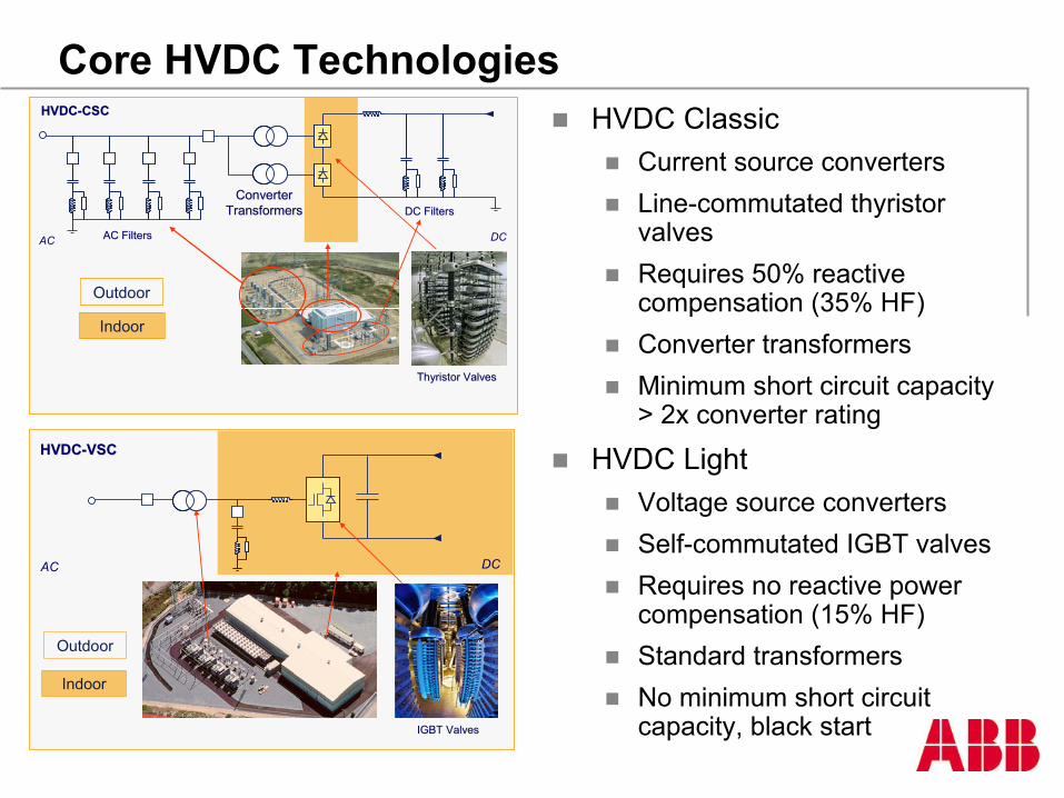
HVDC LightVoltage source convertersSelf-commutated IGBT valvesRequires no reactive power compensation (15% HF)Standard transformersNo minimum short circuit capacity, black start
HVDC Converter Arrangements
HVDC ClassicThyristor valves
Thyristor modules
Thyristors
Line commutated
HVDC LightIGBT valves
IGBT valve stacks
StakPaks
Submodules
Self commutated
SingleValve
DoubleValve
QuadrupleValve
Thyristor Module
Thyristors
IGBT Valve Stacks
StakPak
Submodule
Chip
Cable Pair
HVDC Classic Control
uR
uS
uT
1 3 5
4 6 2
Id
Ud
IR
IS
IT
IR
IS
αu
IT
Control of VSC Based HVDC Transmission
Principle control of HVDC-Light
DCvoltagecontrol
uDC-ref1
uDC1
+
-
uAC1uAC-ref1
pref1
DCvoltagecontrol
uDC-ref2
uDC2
+
-
uAC2 uAC-ref2
pref2 q ref2
ACvoltagecontrol
PWMinternalcurrentcontrol
PWMinternalcurrentcontrol
qref1
ACvoltagecontrol
+
-i i
K
K
K
K
AC Line Voltages OPWM
HVDC Light Plant Layout, ±150 kV, 175- 555 MW
Phase reactors
Coolers
Cooling system
DC Filter
AC filter
Control and auxiliary
Valves
500 kV AC ± 500 kV ± 600 kV ± 800 kV 500 kV AC 765 kV ACTwo Single
Annual Payment, 30 years @ rate of 10% $427,775,177 $214,120,963 $232,440,849 $255,136,504 $324,507,028 $440,960,827$142.59 $71.37 $77.48 $85.05 $108.17 $146.99
Cost per MWh @ Utilization Factor of 65% $25.04 $12.53 $13.61 $14.94 $19.00 $25.81
No of conductors/pole/phase 2 3 3 3 2 2Conductor (ohms/mile) ac or dc @ temp of: 50 0.0420 0.0364 0.0364 0.0364 0.0420 0.0420Line/Pole Current (Amps) 1755 3000 2500 1875 1755 1204Conductor current density (A/mm^2) 0.610 0.695 0.579 0.435 0.610 0.419Losses @ full load 291 209 159 109 291 137Losses at full load in % 9.69% 6.96% 5.29% 3.63% 9.69% 4.56%Cost of losses @ UF & $/kW of: 65% $1,500 $283,503,864 $203,705,153 $154,868,162 $106,308,654 $283,503,864 $133,522,581
Total No. Series Capacitors
Total No. Shunt ReactorsTotal No. Transformers
No. Shunt Capacitors
Total line distance in miles Transmission Line CostTotal Transmission Cost + 10% contingency
Cost per kW-Yr
No. of ac line segmentsNo. of series capacitors per line segment
Total No. AC or DC SubstationsNo. Shunt Reactors per ac line segment
Alternative
Line voltage (kV)Capital Cost
No. of SVC's
Rated Power (MW)
HVDC stations & AC substations incl reactive compTransmission Line (cost/mile)Transmission Line R/W (cost/mile)
Cost Comparison of Transmission Alternatives
4000
5000
6000
7000
8000
1 2 3 4 5 6 7 8 9 10Percent line losses
MU
SD
Power 12000 MWLine length 2000 km800 kV AC 8 lines1000 kV AC 5 lines500 kV DC 4 lines800 kV DC 2 lines
Cost of transmitting 12000 MW 2000 km
Comparison of overall line design800 kV
1000 kV
±600 kV
±800 kV
Itaipu 600 kV HVDC Line Performance
Itaipu 765 kV AC Line Performance
Three Gorges China 3000 MW
The thyristor valve hall
±800 kV, 3600 MW Converter Station
Bypassbreaker
Y/D
Y/Y
Convertertransformer Transformer
bushing
Thyristor valves in valve hall
Wall bushing
AC Filter
Y/D
Y/Y
DC line
Grounding switch
Isolating switch
Surgearrester
Smoothing reactor PLC
capacitor
DC filter capacitors
Voltage divider
Bypass switch
800 kV HVDC- one pole
Exposed to 800 kV dc
Long term test circuit for 800 kV HVDC
Testing for valve hall clearances
Valve Hall 800 KV HVDC
800 kV HVDC station
HVDC Light rating increase to 1100 MWElements common to existing systems
IGBT chip
IGBT submodule
IGBT StakPak
IGBT module or stack
Control system
Cooling system
DC capacitor
Increased dc current – six submodules per StakPak rather than fourIncreased dc voltage (150 kV to 320 kV)
Valve stacks comprised of IGBT modules with 26 positions arranged horizontally
Modules connected in series at site to reach rated voltage – elimination of valve enclosures used for the lower voltages
DC voltage still lower than that commonly used for conventional HVDC
Higher ac voltage on ac filter bus – 400 kVDevelopment parallels that for conventional HVDC thyristor valvesCable and cable accessories type tested to 320 kV, accelerated life tests to be completed this year
HVDC Converter Development
0200400600800
100012001400160018002000
1970
1973
1976
1979
1982
1985
1990
1993
1996
1999
2002
2005
2008
2011
Classic MW Classic kV Light MW Light kV
10
100
1000
10000
20 60 80 150 300 500 800Voltage in kV
Pow
er in
MW
Power Ranges HVDC-Classic and HVDC-Light
Back to back
HVDC Light
HVDC
Tapping OVHD HVDC with Large VSC ConvertersHVDC Tap
Reverse power by polarity reversalElectronic clearing of dc line faultsFast isolation of faulty convertersReactive power constraintsMomentary interruption due to CF at tapLimitations on tap rating, location and recovery rate due to stability
HVDC Light TapPolarity reversal if main link is bidirectionalCannot extinguish dc line fault current contribution without special provision, e.g., diode coupling for inverterNo interruption to main power transfer due to CF at tapLess limitations on tap rating and locationCascade VSC connection for lower tap ratingNo reactive power constraintsImproved voltage stability
Offshore Applications of HVDC LightOffshore Wind Farms
Long cable transmission to shore Voltage regulationWind generator excitation powerBlack start
Oil and Gas ProductionLong cable transmission from shoreFeed platform loadVariable speed compressor drivesVoltage regulationReduced weight and volumeReduced emissionsGreater efficiencyTroll – no outages since 2005!
Valhall, BP
EkofiskValhall
B) ListaA)Åna-Sira
NyckeldataValhall är BP:s största plattform I Nordsjön
Under byggnad
HVDC Light-systemen ska skötaall kraftmatning till plattformen
Ger betydande miljöfördelar ochminskar behovet av personal påplattformen
1 x 78 MW, 290 km sjökabel
Troll: I drift sedan 2005, inga fel!
Client: Nordic Energy Link, Estonia
Contract signed: April 2005
In service: November 2006
Project duration: 19 months
Capacity: 350 MW, 365 MW low ambient
AC voltage: 330 kV at Harku
400 kV at Espoo
DC voltage: ±150 kV
DC cable length: 2 x 10⁵ km (31 km land)
Converters: 2 level, OPWM
Special features: Black start Estonia, no diesel
Rationale: Electricity trade
Asynchronous Tie
Long cable crossing
Dynamic voltage support
Black start
Estlink – HVDC Light between Estonia & Finland
Estlink – full power after 19 months
NorNed Cable HVDC Project The longest underwater high-voltage cable in the world. Clients: Statnett and TenneTTransmission capacity: 700 MWDC Voltage: ± 450 kVLength of DC cable: 2*580 kmWater depths: Up to 410 mProject start: January 2005Completion time: Approx. three years
Customer benefits with HVDCShorter project time due to easier permitting ( 2 – 3 years )Increased power transfer existing a.c. lines ( approx 200 MW)Voltage and reactive power control