84
HW for Chapter 1 Review Questions: 3, 4, 5, 6, 7, 8, and 11 Exercises: 16, 18, 21, 22, 23, and 24 2.1
| Date post: | 24-Dec-2015 |
| Category: |
Documents |
| Upload: | morgan-harrell |
| View: | 215 times |
| Download: | 1 times |

HW for Chapter 1
Review Questions:3, 4, 5, 6, 7, 8, and 11
Exercises: 16, 18, 21, 22, 23, and 24
2.1

2.2
Chapter 2
Network Models
Copyright © The McGraw-Hill Companies, Inc. Permission required for reproduction or display.

A Network is .. A combination of hardware (HW) and
software (SW) that send data from one location to another. HW: physical equipment that carries
signals from one point of the network to another
SW: instruction sets that make possible the services that we expect from a network.
2.3
Data transformed into the form of electromagnetic
signals when sent along a transmission medium (link).

2.4
2-1 LAYERED TASKS
• Sender, Receiver, and Carrier• Hierarchy
Topics discussed in this section:

Network Architicture General blue prints that guide the
design and implementation of networks.
Examples: OSI architicture Internet architicture
Abstraction of the different services and procedures.
Abstraction naturally leads to layering.
2.5

Concept of Layers We use the concept of layers in our
daily life. As an example, let us consider two
friends who communicate through postal mail. The process of sending a letter to a friend would be complex if there were no services available from the post office.
2.6

2.7
Figure 2.1 Tasks involved in sending a letter

Hierarchy The tasks
must be performed in the order specified by the hierarchy of the layers!
2.8

Concept of Layers Each layer provides a specific set
of services. Services are provided through the
definition of protocols. Each layer uses the services
provided by the lower/above layers.
Layers use protocols to communicate with each others.
2.9

Concept of Layers Each layer provides a specific set
of services. Layering provides two nice
features: Decomposes the problem of building
a network into more manageable components.
Provides a more modular design, modifying the functionality of the different layers without affecting the whole system!
2.10

2.11
2-2 THE OSI MODEL
• Layered Architecture• Peer-to-Peer Processes• Encapsulation
Topics discussed in this section:

The OSI Model An ISO standard that covers all
aspects of network communications is the Open Systems Interconnection (OSI) model.
An open system is a set of protocol that allows any two different systems to communicate regardless of their underlying architecture (H/W and S/W).
2.12
ISO is the organization.OSI is the model.

The OSI Model The OSI model is a layered framework
for the design of network systems that allows for communication between all types of computer systems.
It consists of seven separate but related layers, each of which defines a part of the process of moving information across a network.
2.13

2.14
Figure 2.2 Seven layers of the OSI model

1/18/2006
15
ISO: International Standards OrganizationOSI: Open Systems Interconnection
Physical
Presentation
Session
Transport
Network
Data link
Application
The ISO/OSI Reference ModelSource: Computer Networks, Andrew Tanenbaum
The protocol stack:
The idea behind the model: Break up the design to make implementation simpler. Each layer has a well-defined function. Layers pass to one another only the information that is relevant at each level. Communication happens only between adjacent layers.

Layered Architecture OSI model consists of 7 layers. Each layer defines a family of functions
distinct from those of the other layers. Within a single machine, each layer calls
upon the services of the layer just below it. e.g. layer 3 uses the services provided
by layer 2 and provides services for layer 4.
2.16

Layered Architecture Between machines, layer x on one
machine communicate with layer x on another machine.
This communication is govern by an agreed-upon series of rules and convention called protocols.
Communication between machines is a peer-to-peer process using the protocols appropriate to a given layer.
2.17

2.18
The interaction between layers in the OSI model

Peer-to-Peer Process At the physical layer, communication is
direct where device A sends a stream of bits to device B. The bits must be converted to a form that can be transmitted to the receiving device.
At the higher layers, communication must move down through the layers on device A over to device B and then back up through the layers.
2.19

Peer-to-Peer Process
Interfaces Between Layers The passing of the data and network
information down/up through the layers in sending/ receiving require an interface between each pair of adjacent layers.
Well-defined interfaces and layer functions provide modularity to a network.
2.20

Organization of the Layers
The seven layers can be thought of as belonging to three subgroups:1)Layers 1,2, and 3 – physical, data
link, and network – are the network support layers.
2)Layers 5,6, and 7 – session, presenation, and application – are user support layers; they allow interoperability among unrelated software systems.
2.21

Organization of the Layers
The seven layers can be thought of as belonging to three subgroups:
3) Layer 4, the transport layer, links the two groups and ensures that what the lower layers have transmitted is in a form that the upper layers can use.
The upper OSI layers almost implemented in S/W; lowers layers are combination of S/W and H/W except for the physical layer which is mostly H/W.
2.22

2.23
Figure 2.4 An exchange using the OSI model
Organization of the Layers

Encapsulation Another aspect of data
communications in the OSI model is encapsulation. The data protion of a packet at level
N-1 carries the whole packet (data and header and maybe trailer) from level N.
Level N-1 is not aware of which part of the encapsulated packet is data and which part is the header or trailer.
For level N-1, the whole packet coming from level N is treated as one logical unit.
2.24

2.25
2-3 LAYERS IN THE OSI MODEL
In this section we briefly describe the functions of each layer in the OSI model.
Physical LayerData Link LayerNetwork LayerTransport LayerSession LayerPresentation LayerApplication Layer
Topics discussed in this section:

Physical layer The physical layer coordinate the
functions required to carry a bit stream over a physical medium including: Dealing with the mathematical and
electrical specifications of the interfaces and transmission medium.
It defines the procedures and functions that physical devices and interfaces have to perform for transmission to occur.
2.26

Physical layer The physical layer is also concerned
with: Physical characteristics of interfaces
and medium. Representation of bits Data rate Synchronization of bits Line configuration Physical topology Transmission mode
2.27

2.28
Figure 2.5 Physical layer

Data Link layer
The data link layer transforms the physical layer to reliable link.
It makes the physical layer appear error-free to the upper layer (network layer).
2.29

2.30
Figure 2.6 Data link layer
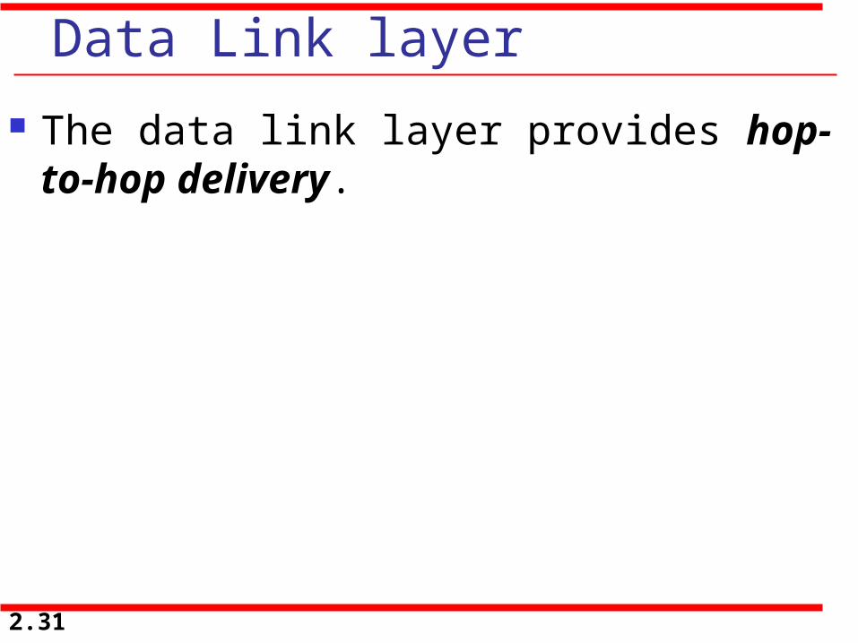
Data Link layer
The data link layer provides hop-to-hop delivery.
2.31

2.32
Figure 2.7 Hop-to-hop delivery

Data Link layer
There are other responsibilities of data link layer include: Framing Physical addressing Flow control Error control Access control
2.33

Network layer The network layer is responsible for the
delivery of individual packets from the source host to the destination host.
At the sender side, data is received from the higher layer (transport) and passed down to the lower layer (data link).
At the sender side, data is received from the lower layer (data link) and passed up to the upper layer (transport).
2.34

2.35
Figure 2.8 Network layer

Network layer Again, the network layer is responsible
for the delivery of individual packets from source to destination.
If two systems are connected to the same link, there is usually no need for a network layer.
If the two systems are attached to different networks with connecting devices between the networks, there is often a need for the network layer to accomplish source-to-destination delivery.2.36
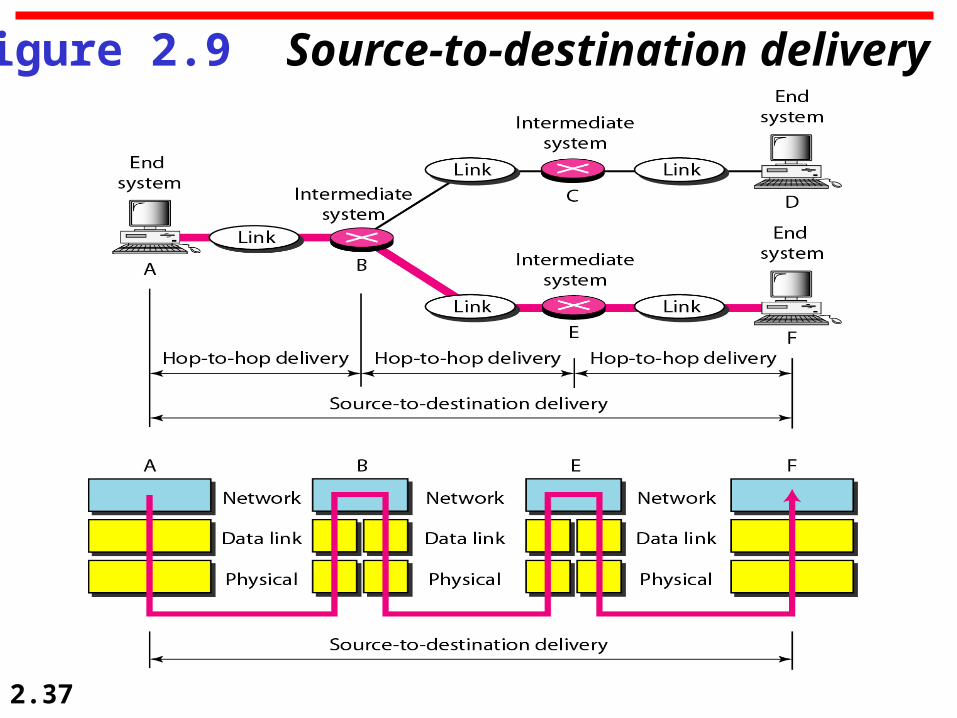
2.37
Figure 2.9 Source-to-destination delivery

Network layer Other responsibilities of network
layer include: Logical addressing Routing
2.38

Transport layer The transport layer is responsible for the
delivery of a message from one process to another.
At the sender side, it receives application data and passes it down to the network layer.
At the receiver side, it receives data from the network layer and passes it up to the appropriate process.
2.39

2.40
Figure 2.10 Transport layer

Transport layer Again, the transport layer is
responsible for the delivery of a message from one process to another.
Unlike the network layer which is source-to-destination delivery, the transport layer is process-to-process delivery of the entire message.
2.41

2.42
Figure 2.11 Reliable process-to-process delivery of a message

Transport layer Other responsibilities of transport
layer: Service-point addressing Segmentation and reassembly Connection control Flow control Error control
2.43

Session layer
The session layer is responsible for dialog control and synchronization.
2.44

2.45
Figure 2.12 Session layer

Session layer Specific responsibilities of the session
layer include: Dialog control Synchronization
2.46

Presentation layer
The presentation layer is concerned with syntax and semantics of the information exchange between two systems.
2.47

2.48
Figure 2.13 Presentation layer

Presentation layer Specific responsibilities of presentation
layer: Translation Encryption Compression
2.49

Application layer
The application layer enables user, weather human or software, to access the network.
It provides user interfaces and support for services such as e-mail, remote file access and transfer, shared database management, and other types of distributed information services.
2.50

2.51
Figure 2.14 Application layer

Application layer Specific responsibilities of presentation
layer: Network virtual terminal File transfer, access, and
management Mail services Directory services
2.52

2.53
Figure 2.15 Summary of layers

2.54
2-4 TCP/IP PROTOCOL SUITE
• The layers in the TCP/IP protocol suite do not exactly match those in the OSI model.
• The original TCP/IP protocol suite was defined as having four layers: host-to-network, internet, transport, and application.
• When TCP/IP is compared to OSI, we can say that the TCP/IP protocol suite is made of five layers: physical, data link, network, transport, and application.
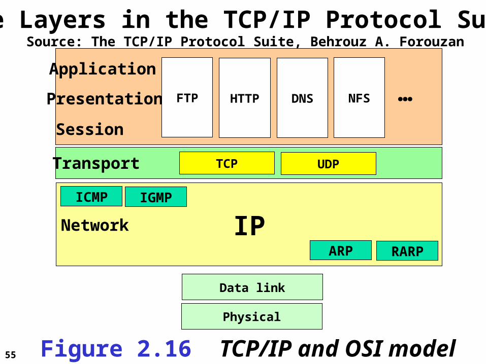
55
The Layers in the TCP/IP Protocol SuiteSource: The TCP/IP Protocol Suite, Behrouz A. Forouzan
Physical
Data link
IPARP RARP
ICMP IGMP
Transport TCP UDP
Network
Session
Presentation
Application
FTP HTTP DNS NFS …
Figure 2.16 TCP/IP and OSI model

2.56
2-4 TCP/IP PROTOCOL SUITE • TCP/IP is a hierarchical protocol made up of interactive modules, each of which provides a specific functionality.•The layers of the TCP/IP protocol suite contain relatively independent protocols.• The term hierarchical means that each upper-level protocol is supported by one or more lower-level protocols.

Physical and Data Link Layers No specific protocol is defined at
this layer, rather, TCP/IP model supports all the standard and proprietary protocols.
For instance, a network in a TCP/IP internetwork can be a local-area network or a wide-area network.
2.57
2-4 TCP/IP PROTOCOL SUITE

Network layer (internetwork layer) TCP/IP at this layer supports the
Internetworking Protocol (IP) There are also some other
protocols that support data movement in this layer. Including: ARP, RARP, ICMP, and IGMP.
2.58
2-4 TCP/IP PROTOCOL SUITE

Internetworking Protocol (IP) Most important protocol of the TCP/IP
network stack! Implements internetworking. IP is an unreliable and connectionless
protocol- a best-effort delivery. It is host-to-host protocol.
2.59
Protocols at The Network Layer

Address Resolution Protocol (ARP) It is used to find the physical address
(NIC) of the node after its Network address is known.
Reverse Address Resolution Protocol (RARP) It is used to find the Internet address
of the node after its physical address is known.2.60
Protocols at The Network Layer

Internet Control Message Protocol (ICMP) It is used by hosts and gateways to
send notification of datagrams ( packets) problem back to the sender.
Internet Group Message Protocol (IGMP) It is used to facilitate the simultaneous
transmission of messages to a group of recipients.
2.61
Protocols at The Network Layer

Transport Layer In this layer, the protocol is
responsible for delivery of message from a process to another process.
2.62
2-4 TCP/IP PROTOCOL SUITE

User Datagram Protocol (UDP) It adds port addresses, checksum
error control, and length information to the data from the upper layer.
Transmission Control Protocol (TCP)
It is reliable and connection-oriented.
2.63
Protocols at The Transport Layer

Stream Control Transmission Protocol (STCP)
It supports the newer application e.g. voice over the Internet.
It combine best features of UDP and TCP.
2.64
Protocols at The Transport Layer

Application Layer The application layer in TCP/IP is
equivalent to the combined session, presentation, and application.
2.65
2-4 TCP/IP PROTOCOL SUITE

2.66
2-5 ADDRESSING
Four levels of addresses are used in an internet employing the TCP/IP protocols: • physical (link ) addresses , • logical (IP) addresses, • port addresses, and • specific addresses.

2.67
2-5 ADDRESSING
Physical AddressesLogical AddressesPort AddressesSpecific Addresses
Topics discussed in this section:

2.68
Figure 2.17 Addresses in TCP/IP

2.69
Figure 2.18 Relationship of layers and addresses in TCP/IP

Physical Addresses It is knwon as link address . It is the address of a node as
defined by its LAN or WAN. The size and format of the address
depends on the network. Ethernet uses 6-bytes (48-bits) NIC
LocalTalk (Apple) uses 1-byte dynamic address
2.70
2-5 ADDRESSING

2.71
In Figure 2.19 a node with physical address 10 sends a frame to a node with physical address 87. The two nodes are connected by a link (bus topology LAN). As the figure shows, the computer with physical address 10 is the sender, and the computer with physical address 87 is the receiver.
Example 2.1

2.72
Figure 2.19 Physical addresses

2.73
As we will see in Chapter 13, most local-area networks use a 48-bit (6-byte) physical address written as 12 hexadecimal digits; every byte (2 hexadecimal digits) is separated by a colon, as shown below:
Example 2.2
07:01:02:01:2C:4B
A 6-byte (12 hexadecimal digits) physical address.
Also known as a MAC address

Logical Addresses Necessary for universal
communications that are independent of underlying physical networks.
Physical address is not enough in an internetwork environment where the different network can have different address formats.
A logical address in the Internet is 32-bits.
No two hosts on the Internet have the same IP address.
2.74
2-5 ADDRESSING

2.75
Figure 2.20 shows a part of an internet with two routers connecting three LANs. Each device (computer or router) has a pair of addresses (logical and physical) for each connection. In this case, each computer is connected to only one link and therefore has only one pair of addresses. Each router, however, is connected to three networks (only two are shown in the figure). So each router has three pairs of addresses, one for each connection.
Example 2.3

2.76
Figure 2.20 IP addresses

2.77
• The physical addresses will change from hop to hop, but the logical addresses usually remain the same.
• No two hosts on the Internet have the same IP address.
Note

Port Addresses It is necessary for the receiver
device that runs multiple process to receive data simultaneously this make a need to label each process
A port address is 16-bits.
2.78
2-5 ADDRESSING

2.79
Figure 2.21 shows two computers communicating via the Internet. The sending computer is running three processes at this time with port addresses a, b, and c. The receiving computer is running two processes at this time with port addresses j and k. Process a in the sending computer needs to communicate with process j in the receiving computer. Note that although physical addresses change from hop to hop, logical and port addresses remain the same from the source to destination.
Example 2.4

2.80
Figure 2.21 Port addresses

2.81
Example 2.5
As we will see in Chapter 23, a port address is a 16-bit address represented by one decimal number as shown.
753
A 16-bit port address represented as one single number.

2.82
The physical addresses change from hop to hop,but the logical and port addresses usually remain the same.
Note

Specific Addresses Examples
e-mail address URL address
Those addresses get changed to the corresponding port and logical address by the sending computer.
2.83
2-5 ADDRESSING

HW for Chapter 2
Review Questions:1, 4, 7, 12, 18
Exercises: 15, 17, 20, 21, 25
2.84


