Page 1
UNCLASSIFIED
The Nation’s Premier Laboratory for Land ForcesApproved for public release
UNCLASSIFIED
Approved for public release
Hybrid Gear Performance Under Loss-of-Lubrication Conditions
Kelsen E. LaBerge (ARL), Stephen P. Berkebile (ARL), Robert F. Handschuh (NASA), Gary D. Roberts (NASA)
American Helicopter Society’s 73rd Annual ForumMay 9-11, 2017
https://ntrs.nasa.gov/search.jsp?R=20170006855 2019-02-25T03:49:28+00:00Z
Page 2
UNCLASSIFIED
The Nation’s Premier Laboratory for Land ForcesApproved for public release
Outline
• Background• Hybrid gear design• Experimental setup• Results• Conclusions• Future work
Page 3
UNCLASSIFIED
The Nation’s Premier Laboratory for Land ForcesApproved for public release
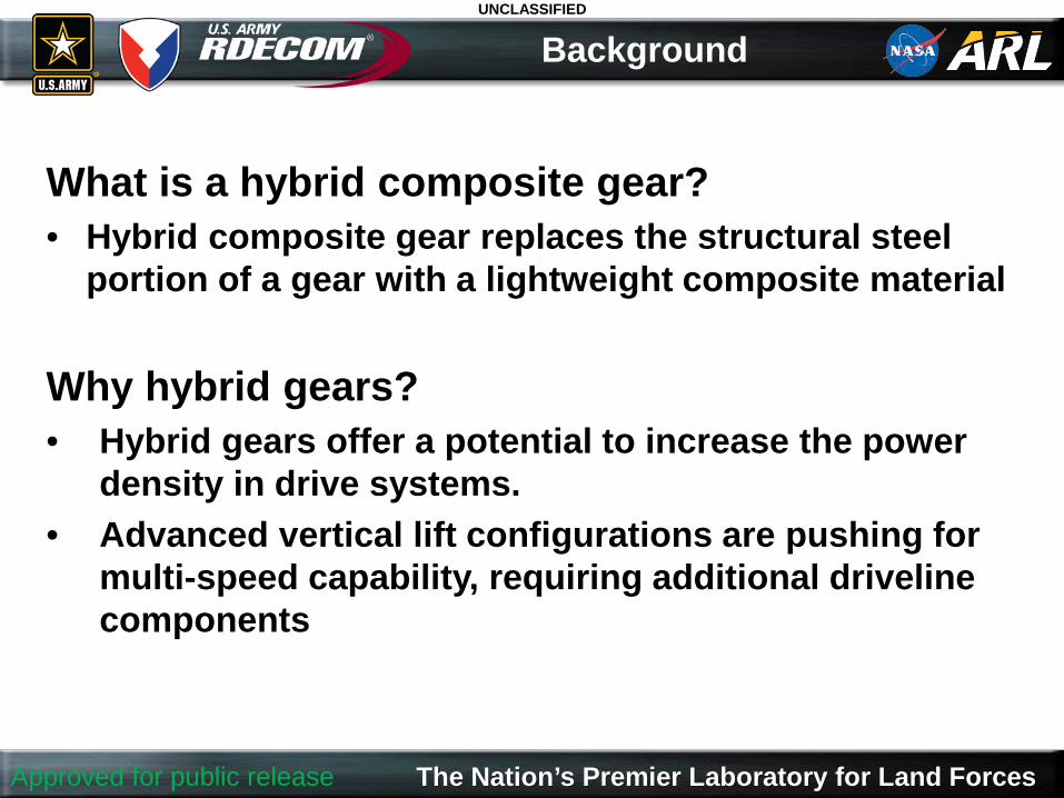
What is a hybrid composite gear?• Hybrid composite gear replaces the structural steel
portion of a gear with a lightweight composite material
Why hybrid gears?• Hybrid gears offer a potential to increase the power
density in drive systems. • Advanced vertical lift configurations are pushing for
multi-speed capability, requiring additional driveline components
Background
Page 4
UNCLASSIFIED
The Nation’s Premier Laboratory for Land ForcesApproved for public release
Past Efforts
Small-Scale
3.5 inch pitch diameter hybrid gears
Large-Scale
16.5 inch pitch diameter hybrid bull gear
• One million cycle endurance test• Static torque test
• One million cycle endurance test at 3300 hp
• Operational testing at 5000 hp• Static torque test on the web
Page 5
UNCLASSIFIED
The Nation’s Premier Laboratory for Land ForcesApproved for public release
What about operation under adverse
conditions?
Page 6
UNCLASSIFIED
The Nation’s Premier Laboratory for Land ForcesApproved for public release
Hybrid Gear Design
Outer composite layers
Outer composite layers
Adhesive film
Adhesive film
Inner composite layers
Machined gear
Triaxial Braid Architecture
12k ±60bias yarns
2X12kaxial yarns
• T700S-50C standard modulus fiber • Prepreg / compression molding approach for flat web element • ACG MTM45-1 resin with MTA241 film adhesive
Page 7
UNCLASSIFIED
The Nation’s Premier Laboratory for Land ForcesApproved for public release
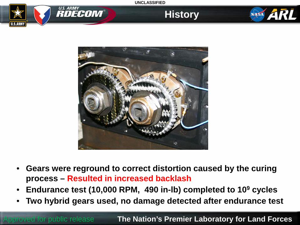
History
• Gears were reground to correct distortion caused by the curing process – Resulted in increased backlash
• Endurance test (10,000 RPM, 490 in-lb) completed to 109 cycles• Two hybrid gears used, no damage detected after endurance test
Page 8
UNCLASSIFIED
The Nation’s Premier Laboratory for Land ForcesApproved for public release
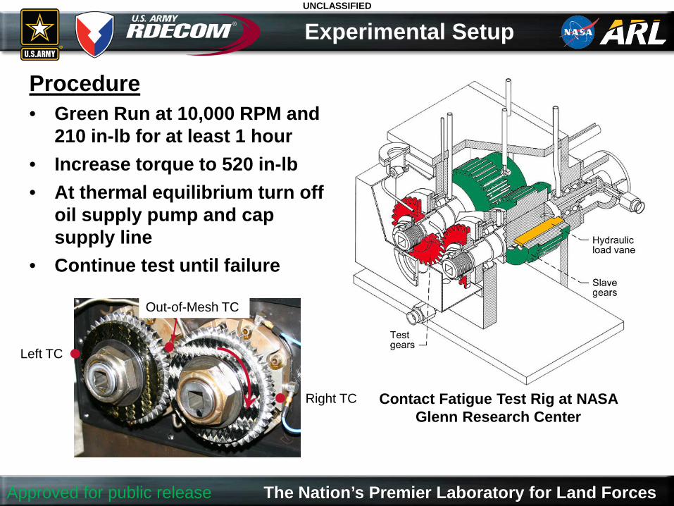
Procedure• Green Run at 10,000 RPM and
210 in-lb for at least 1 hour• Increase torque to 520 in-lb• At thermal equilibrium turn off
oil supply pump and cap supply line
• Continue test until failure
Experimental Setup
Contact Fatigue Test Rig at NASA Glenn Research Center
Right TC
Left TC
Out-of-Mesh TC
Page 9
UNCLASSIFIED
The Nation’s Premier Laboratory for Land ForcesApproved for public release
Run Time (min)
0 0.5 1 1.5 2 2.5 3
Tem
pera
ture
(F)
150
300
450
600
Out of Mesh Left Gear Right Gear
Results - Baseline
Steel Driving Steel (Unshrouded)
Page 10
UNCLASSIFIED
The Nation’s Premier Laboratory for Land ForcesApproved for public release
Results - Experiment 1
Hybrid Driving Hybrid
• After shutdown loss-of-torque was verified
• Visual inspection showed that the hub had rotated with respect to the teeth on the left gear
0 2.5 5
Tem
pera
ture
(F)
200
300
400
500
Run Time (min)
50 100 150 200 250
Out of Mesh Left Gear Right Gear
Page 11
UNCLASSIFIED
The Nation’s Premier Laboratory for Land ForcesApproved for public release
Results - Experiment 1
Gap
Crushed composite
Disassembled left gear
Approximate location of interlock pattern
Modified right gear
Page 12
UNCLASSIFIED
The Nation’s Premier Laboratory for Land ForcesApproved for public release
Experiment 2
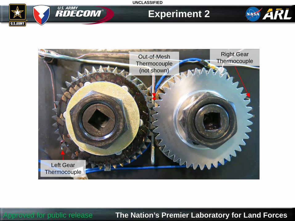
Left Gear Thermocouple
Right Gear Thermocouple
Out-of-Mesh Thermocouple
(not shown)
Page 13
UNCLASSIFIED
The Nation’s Premier Laboratory for Land ForcesApproved for public release
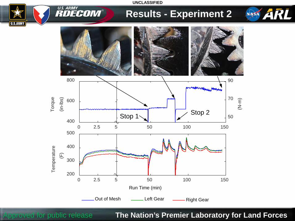
Results - Experiment 2
0 2.5 5
Torq
ue
(in-lb
s)
400
600
800
50 100 150
(N-m
)
50
70
90
0 2.5 5
Tem
pera
ture
(F)
200
300
400
500
Run Time (min)
50 100 150
Out of Mesh Left Gear Right Gear
Stop 2Stop 1
Page 14
UNCLASSIFIED
The Nation’s Premier Laboratory for Land ForcesApproved for public release
Results - Experiment 2
0 2.5 5
Torq
ue
(in-lb
s)
400
600
800
50 100 150
(N-m
)
50
70
90
0 2.5 5
Tem
pera
ture
(F)
200
300
400
500
Run Time (min)
50 100 150
Out of Mesh Left Gear Right Gear
Stop 2Stop 1
Stop 1• Torque transfer verified• Black lines documented on teeth• Restarted experiment dry and
reapplied load
Page 15
UNCLASSIFIED
The Nation’s Premier Laboratory for Land ForcesApproved for public release
Results - Experiment 2
0 2.5 5
Torq
ue
(in-lb
s)
400
600
800
50 100 150
(N-m
)
50
70
90
0 2.5 5
Tem
pera
ture
(F)
200
300
400
500
Run Time (min)
50 100 150
Out of Mesh Left Gear Right Gear
Stop 2Stop 1
Stop 2• Torque transfer verified• Gears photographed• Restarted experiment
dry and reapplied load
Page 16
UNCLASSIFIED
The Nation’s Premier Laboratory for Land ForcesApproved for public release
Results - Experiment 2
0 2.5 5
Torq
ue
(in-lb
s)
400
600
800
50 100 150
(N-m
)
50
70
90
0 2.5 5
Tem
pera
ture
(F)
200
300
400
500
Run Time (min)
50 100 150
Out of Mesh Left Gear Right Gear
Stop 2Stop 1
Page 17
UNCLASSIFIED
The Nation’s Premier Laboratory for Land ForcesApproved for public release
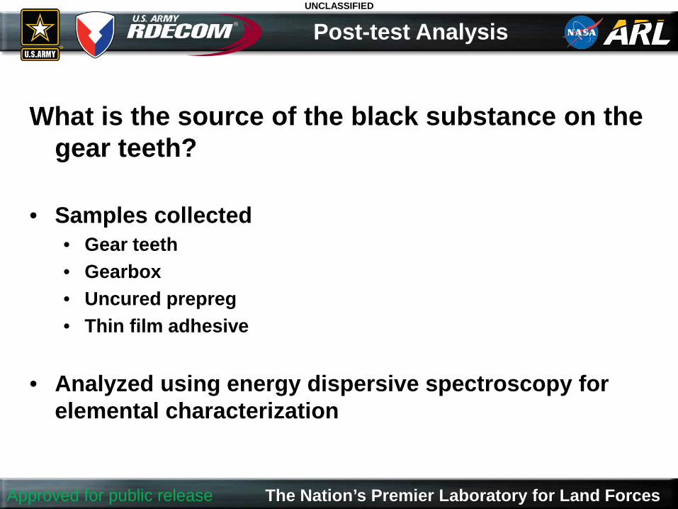
What is the source of the black substance on the gear teeth?
• Samples collected• Gear teeth• Gearbox• Uncured prepreg• Thin film adhesive
• Analyzed using energy dispersive spectroscopy for elemental characterization
Post-test Analysis
Page 18
UNCLASSIFIED
The Nation’s Premier Laboratory for Land ForcesApproved for public release
EDS Analysis
Gear Tooth Surface Sample Gearbox Residue Sample
Page 19
UNCLASSIFIED
The Nation’s Premier Laboratory for Land ForcesApproved for public release
EDS Analysis
Epoxy on Prepreg Thin Film Adhesive
Page 20
UNCLASSIFIED
The Nation’s Premier Laboratory for Land ForcesApproved for public release
• The mechanical interlock design in a hybrid gear is important during an oil-out event
• The pinned interlock pattern was shown to better withstand this type of event
• At increased temperatures, softened polymer at the gear mesh may act as a lubricant or sulfur-containing lubricant additive
Conclusions
The effects of material degradation on hybrid gear design for oil-out conditions needs further investigation
Page 21
UNCLASSIFIED
The Nation’s Premier Laboratory for Land ForcesApproved for public release
• Isolate source of performance increase• Increased backlash• Polymer lubricant
• Can polymer flow phenomenon be used to increase survivability of steel gears during an oil-out event?
Future Work
Page 22
UNCLASSIFIED
The Nation’s Premier Laboratory for Land ForcesApproved for public release
Questions?
Acknowledgements:• A&P Technology – Provided hybrid gears
used for this project as part of a NASA SBIR
• Roger Tuck – Technician support• ARL’s Weapons and Materials Research
Directorate – EDS


![Arl -skf_in_india_story[1]](https://static.documents.pub/doc/80x56/547a4327b4af9fef158b4a6a/arl-skfinindiastory1.jpg)


