Hybrid Layered Video Encoding for Mobile Internet-Based Computer Vision and
Multimedia Applications
Suchendra M. Bhandarkar1, Siddhartha Chattopadhyay2, and Shiva Sandeep Garlapati1
1 Department of Computer Science, The University of Georgia, Athens, GA 30602-7404, USA
2 Google Inc., Mountain View, CA 94043, USA
Abstract. Mobile networked environments are typically resource constrained in terms of the available bandwidth and battery capacity on mobile devices. Real-time video applications entail the analysis, storage, transmission, and rendering of video data, and are hence resource-intensive. Since the available bandwidth in the mobile Internet is constantly changing, and the battery life of a mobile video application decreases with time, it is desirable to have a video representation scheme that adapts dynamically to the available resources. A Hybrid Layered Video (HLV) encoding scheme is proposed, which comprises of content-aware, multi-layer encoding of texture and a generative sketch-based representation of the object outlines. Different combinations of the texture- and sketch-based representations result in distinct video states, each with a characteristic bandwidth and power consumption profile. The proposed HLV encoding scheme is shown to be effective for mobile Internet-based multimedia applications such as background subtraction, face detection, face tracking and face recognition on resource-constrained mobile devices.
Keywords: video streaming, layered video, mobile multimedia.
1 Introduction
The increasing deployment of broadband networks and simultaneous proliferation of low-cost video capturing and multimedia-enabled mobile devices, such as pocket PCs, cell phones, PDA’s and iPhones during the past decade have triggered a new wave of mobile Internet-based multimedia applications. Internet-scale mobile multimedia applications such as video surveillance, video conferencing, video chatting and community-based video sharing are no longer mere research ideas, but have found their way in several practical commercial products. Most multimedia applications typically entail the analysis, transmission, storage and rendering of video data and are hence resource-intensive. Mobile network environments, on the other hand, are typically resource constrained in terms of the available bandwidth and battery capacity on the mobile devices. Mobile Internet environments are also characterized by constantly fluctuating bandwidth and decreasing device battery life
HLV Encoding for Mobile Internet-Based Computer Vision 111
as a function of time. Consequently, it is desirable to have a hierarchical or layered video encoding scheme where distinct layers have different resource consumption characteristics [32].
Traditional layered video encoding, as used by the MPEG-4 Fine Grained Scalability profile (MPEG-FGS), is based on the progressive truncation of DCT or wavelet coefficients [12]. There is a tradeoff between the bandwidth and power consumption requirements of each layer and the visual quality of the resulting video, i.e., the lower the resource requirements of a video layer, the lower the visual quality of the rendered video [12]. Note that the conventional MPEG-FGS layered encoding is based on the spectral characteristics of low-level pixel data. Consequently, in the face of resource constraints, the quality of the lower layer videos may not be adequate to enable high-level computer vision or multimedia applications. For a layered video encoding technique to enable a high-level computer vision or multimedia application, it is imperative that the video streams corresponding to the lower encoding layers contain enough high-level information to enable the application at hand while simultaneously satisfying the resource constraints imposed by the mobile network environment.
In this chapter, a Hybrid Layered Video (HLV) encoding scheme is proposed, which comprises of content-aware, multi-layer encoding of texture and a generative sketch-based representation of the object outlines. Different combinations of the texture- and sketch-based representations result in distinct video states, each with a characteristic bandwidth and power consumption profile. The high-level content awareness embedded within the proposed HLV encoding scheme is shown to enable high-level vision applications more naturally than the traditional layered video encoding schemes based on low-level pixel data. The proposed HLV encoding scheme is shown to be effective for mobile Internet-based computer vision and multimedia applications such as background subtraction, face detection, face tracking and face recognition on resource-constrained mobile devices.
2 Overview of Proposed Scheme
Video reception and playback on a mobile device such as a PDA, pocket-PC, multimedia-enabled mobile phone (for example, the iPhone), or a laptop PC operating in battery mode, is a resource-intensive task in terms of CPU cycles, network bandwidth and battery power [32]. Video reception and playback typically results in rapid depletion of battery power in the mobile device, regardless of whether the video is streamed from a hard drive on the device, or from a remote server. Several techniques have been proposed to reduce resource consumption during video playback on the mobile device [10], [11], [22], [26], [27]. These techniques use various hardware and software optimizations to reduce resource consumption during video reception and playback. Typically, resource savings are realized by compromising the quality of the rendered video. This tradeoff is not always desirable, since the user may have very well chosen to watch the video at its highest quality if sufficient battery power were available on the device. It is desirable to formulate and implement a multi-layer encoding of the video such that distinct layers of the video display different resource consumption characteristics. The lowest layer should
112 S.M. Bhandarkar, S. Chattopadhyay, and S.S. Garlapati
consume the fewest resources during video reception, decoding and rendering. The resource consumption during video reception, decoding and rendering should increase as more layers are added to the video. Typically, fewer the available resources to receive, decode and render the video, the lower the quality of the rendered video on the mobile device [12]. In light of the aforementioned tradeoff between resource consumption and video quality, it is necessary to enhance quality of the lower video layers in order to ensure that the quality of the rendered video is acceptable.
Traditional layered video encoding, as used by the MPEG-4 Fine Grained Scalability profile (MPEG-FGS), is customized for varying bitrates, rather than adaptive resource usage. In this paper, we present the design and implementation of a novel Hybrid Layered Video (HLV) encoding scheme. The proposed representation is termed as “hybrid” on account of the fact that its constituent layers are a combination of standard MPEG-based video encoding and a generative sketch-based video representation. The input video stream is divided into two components: a sketch component and a texture component. The sketch component is a Generative Sketch-based Video (GSV) representation, where the outlines of the objects of the video are represented as curves [6]. The evolution of these curves, termed as pixel-threads, across the video frames is modeled explicitly in order to reduce temporal redundancy. A considerable body of work on object-based video representation using graphics overlay techniques has been presented in the literature [20], [21], [30]. These methods are based primarily on the segmentation of the video frames into regions and the subsequent representation of these regions by closed contours. A major drawback of the aforementioned contour-based representation is the fact that the complexity of the representation increases significantly with an increasing number of contours in the video frames. In contrast, the proposed GSV representation uses sparse parametric curves, instead of necessarily closed contours, to represent the outlines of objects in the video frames. This ensures that the number of graphical objects that one needs to overlay is small. In addition, whereas closed contours are capable of addressing local region-based consistency, global shape-based information may be seriously compromised. This is not so in the case of the proposed GSV representation, which ensures that the global shape is correctly represented. Although contour-based representations have been very successful in some specific applications involving low bitrate videos such as video phones [15], generic contour-based video representations for a wider class of power-constrained devices have, thus far, not been studied in detail.
The texture component in the proposed HLV encoding scheme is represented by three layers; a base layer video, an intermediate mid-layer video, and the original video. The base layer represents a very low bitrate video with very low visual quality whereas the highest layer in the HLV representation denotes the original video. The base layer video can be augmented by the object outlines that are emphasized with dark contours using the Generative Sketch-based Video (GSV) representation mentioned above. This ensures that the visual quality of the base layer is improved significantly. The visual quality of the mid-layer video is higher than that of the base layer video, but lower than that of the original video. The quality of the mid-layer video is further enhanced via high-level object-based re-rendering of the video at multiple scales of resolution. The result is termed as a Features, Motion and Object-Enhanced Multi-Resolution (FMOE-MR) video [5]. Note that although the visual
HLV Encoding for Mobile Internet-Based Computer Vision 113
quality of the mid-layer video is lower than that of the original video, the semantically relevant portions of the frames in the mid-layer video are highlighted by selectively rendering them at higher resolution, thus enhancing the overall viewing experience of the end user.
We show that the various video layers in the proposed HLV representation have different power consumption characteristics. Thus, the overall power consumption of an HLV-encoded video depends on the combination of layers used during decoding and rendering of the video on the mobile end user device. A direct benefit of the proposed HLV representation is that the video content can be received, decoded and rendered at different levels of resource consumption on the mobile device. The proposed HLV representation is thus extremely well suited for video streaming to power-constrained devices, such as multimedia-enabled mobile phones, PDAs, pocket-PCs and laptop computers operating in battery mode, where the available bandwidth and power for video reception and playback are typically observed to change over the duration of video reception and playback. A schematic depiction of the proposed Hybrid Layered Video (HLV) representation is given in Fig 1.
Fig. 1. The Hybrid Layered Video (HLV) Scheme
In the following sections, we elaborate upon the two components of the proposed HLV representation, i.e., the sketch component, VSKETCH and the texture component, VTEXTURE. This is followed by a description of how to combine the various video layers comprising the VSKETCH and VTEXTURE components to arrive at a resource-scalable video representation. We discuss issues pertaining to the implementation of the proposed HLV representation followed by a presentation and analysis of the experimental results. Finally, we conclude the chapter with an outline of future research directions.
3 Creating Video Component vsketch
The sketch-based video component VSKETCH essentially represents the outlines of the objects in the video. We describe a technique to represent a video stream as a sequence of sketches, where each sketch in turn is represented by a sparse set of
114 S.M. Bhandarkar, S. Chattopadhyay, and S.S. Garlapati
parametric curves. The resulting video representation is termed a Generative Sketch-based Video (GSV). The video is first divided into a series of Groups of Pictures (GOPs), in a manner similar to standard MPEG video encoding [28]. Each GOP consists of N frames (typically, N = 15 for standard MPEG/H.264 encoding) where each frame is encoded as follows:
1. The object outlines are extracted in each of the N frames. These outlines are represented as a sparse set of curves.
2. The curves in each of the N frames are converted to a suitable parametric representation.
3. Temporal consistency is used to remove spurious curves, which occur intermittently in consecutive frames, to remove an undesired flickering effect.
4. Finally, the parametric curves in the N frames of the GOP are encoded in a compact manner. The first frame of the GOP enumerates the curve parameters in a manner that is independent of their encoding, analogous to the I-frame in MPEG H.264 video encoding standard. The remaining N-1 frames in the GOP are encoded using motion information derived from previous frames, in a manner analogous to the P-frames in the MPEG H.264 video encoding standard.
The proposed GSV encoding scheme is similar the MPEG video encoding standard. The GOP is a well established construct in the MPEG standard that enables operations such as fast forward, rewind and frame dropping to be performed on the encoded video stream. Motion vectors are used in the GSV encoding scheme to reduce temporal redundancy in a manner similar to MPEG video encoding, where motion vectors are used to describe the translation of frame blocks relative to their positions in previous frames. The error vector, in the case of the GSV encoding scheme, has the same form as the encoded representation of the moving object(s) in the video. This is analogous to the MPEG video encoding standard, where the encoding error is represented in the form of macroblocks similar to the macroblock representation of the moving object(s) in the video.
Fig. 2. The creation of pixel-threads for a video frame (a) The original video frame; (b) Edges detected in the video frame, and filtered to remove small, spurious edges; (c) Break-points detected in the edge contours generated in the previous step
The parametric curves used to represent the object outlines in each frame are termed as pixel-threads. A pixel-thread is derived from a polyline P:[0, N], which is a continuous and piecewise linear curve made of N connected segments. A polyline can be parameterized using a parameter α ϵ ℜ (set of real numbers) such that P(α) refers
HLV Encoding for Mobile Internet-Based Computer Vision 115
to a specific position on the polyline, with P(0) referring to the first vertex of the polyline and P(N) referring to its last vertex. Note that the pixel-threads contain information only about the vertices (or break points) of the polyline. Note that these break points can be joined by straight line segments (as in the case of a polyline), or by more complex spline-based functions to create smooth curves.
The pixel-threads essentially depict the outlines of objects in the underlying video stream. Each video frame is associated with its own collection of pixel-threads termed as a Pixel-thread-Pool. Thus, successive video frames are associated with successive Pixel-thread-Pools. Due to the temporal nature of the video, the pixel-threads and Pixel-thread-Pools are modeled as dynamic entities that evolve over time to generate the outlines of the moving objects in the video. The dynamic nature of the pixel-threads is modeled by the processes of birth and evolution of pixel-threads over time. We provide a detailed description of these processes in the following subsections.
3.1 Birth of Pixel-Threads
For a given video frame, the Pixel-thread-Pool is created by first generating (or sketching) the outlines of the objects in the video frame, and then representing these outlines parametrically in the form of pixel-threads.
Generating a sketch from a video frame. The edge pixels in a video frame are extracted using the Canny edge detector [4]. The edge pixels are grouped to form one-pixel wide edge segments or edgels, many of which are intersecting. Edgels of small length are removed to avoid excessively cluttered sketches. The threshold below which an edgel is considered “small” depends on the screen size. Since GSV encoding is typically meant for mobile devices with small screens, the removal of these small edgels typically does not produce any adverse effect. It must be noted that the edge detection process is inherently sensitive to noise and several edgels may, in fact, be noisy artifacts. The edgels extracted in two successive frames may result in a flickering effect, wherein an edgel in a previous frame may disappear in the current frame, even in instances where the human eye can clearly discern an object boundary. A method to reduce this flickering effect is described in Section 3.4. Creating Pixel-Threads from a Sketch. The sketch thus obtained is converted to an approximate parametric representation using curve approximation techniques proposed by Rosin and West [29]. Rosin and West [29] describe the implementation and demonstrate the performance of an algorithm for segmenting a set of connected points resulting in a combination of parametric representations such as lines, circles, ellipses, super-elliptical arcs, and higher-order polynomial curves. The algorithm is scale invariant (i.e., it does not depend on the size of the edgels, or the size of the frame), nonparametric (i.e., it does not depend on predefined parameters), general purpose (i.e., it works on any general distribution of pixels depicting object outlines in any given video frame), and efficient (i.e., has low computational time complexity). Since a detailed discussion of the algorithm is beyond the scope of the paper, it suffices to mention that we use this algorithm to determine break points on the various connected components (i.e., edge segments) that are generated after the edge pixels have been detected.
116 S.M. Bhandarkar, S. Chattopadhyay, and S.S. Garlapati
A curved edge segment is represented by a series of break points along the curve, determined using the algorithm of Rosin and West [29]. The curved edge segment is deemed to represent a portion of the outline of an object in the scene. Thus, the fitting of straight lines between the break points results in a rendering of an approximate version of the original curve. The break points are essentially points of significance along the curve, such as corners and high-curvature points. Altering the level of significance or threshold for break-point detection allows various levels of (break-point based) approximation of the contours in the video frame.
The break points along the curve are represented efficiently as a chain-coded vector. For each approximated curve i, one of the end points (first or last break point) is represented using absolute coordinates {x0, y0} whereas the pth break point, where p > 0, is represented by coordinates relative to those of the previous break point; i.e.{δxp, δyp} where δxp = xp - xp-1 and δyp = yp - yp-1. The resulting chain-coded vectors constitute the pixel-threads which are approximations to the original curve. Fig. 2 illustrates the process by which pixel-threads are generated for a given video frame. Note that the pixel-thread creation procedure is performed offline during the encoding process.
Fig. 3. Illustration of the process of establishing pixel-thread correspondence for a frame j and the current All-Threads-Pool Ψ
3.2 Evolution of a Pixel-Thread
Due to the temporal redundancy in a video sequence, a majority of the corresponding pixel-threads in successive video frames are often similar in shape and size. This temporal redundancy can be exploited to evolve some of the pixel-threads in the current frame to constitute the Pixel-thread-Pool for the successive frame. An advantage of evolving the pixel-threads over successive video frames is the fact that a pixel-thread, once born in a video frame, requires only motion information to characterize its behavior in successive frames. Motion modeling significantly reduces the amount of information required to render the set of pixel-threads belonging to the next frame. This results in a compact representation of the dynamic pixel-threads. The evolution parameters are determined during the encoding process, which is performed offline and typically not resource constrained. As will be shown subsequently, the
HLV Encoding for Mobile Internet-Based Computer Vision 117
encoding is done in a manner such that the decoding is simple, and can be done in real time by a resource constrained device.
The evolution of pixel-threads between two successive Pixel-thread-Pools, say TP1 and TP2, involves two steps; (a) establishing the pixel-thread correspondence between the two Pixel-thread-Pools, and (b) estimating the motion parameters.
Establishing Pixel-Thread Correspondence. In order to model the underlying motion accurately, it is essential to establish the correspondence between pixel-threads, belonging to the Pixel-thread-Pools of two consecutive frames in the video stream. In order to determine the correspondence between pixel-threads in TP1 and TP2 one needs to determine for each pixel-thread in TP1 its counterpart in TP2.
First, we need to predict a position to which a pixel-thread T1 ϵ TP1 is expected to move in the next frame. The predicted pixel-thread, say T′, can be determined using a suitable optical flow function OpF( ), such that
T′ = OpF(T1) (1)
The function OpF( ) computes the coordinates of the break points of the pixel-thread T′ ϵ TP2, given the coordinates of the break points of pixel-thread T1 ϵ TP1. The function OpF( ) implements a sparse iterative version of the Lucas-Kanade optical flow algorithm designed for pyramidal (or multiscale) computation [3]. The Lucas-Kanade algorithm is a popular version of a two-frame differential technique for motion estimation (also termed as optical flow estimation). For each break point location (x, y) of a pixel-thread, if the corresponding pixel location in the original image (frame) has intensity I(x, y); and is assumed to have moved by δx and δy between the two frames, then the image constraint equation is given by:
Icurrent-frame(x, y) = Inext-frame(x + δx, y + δy)
The Lucas-Kanade algorithm essentially embodies the above image constraint equation. The pyramidal implementation of the Lucas-Kanade algorithm computes the optical flow in a coarse-to-fine iterative manner. The spatial derivatives are first computed at a coarse scale in scale space (i.e., in a pyramid), one of the images is warped by the computed deformation, and iterative updates are then computed at successively finer scales.
Once the pixel-thread T′ is obtained from T1 via the optical flow function, we hypothesize that if pixel-thread T1 in Pixel-thread-Pool TP1 does indeed evolve to a corresponding pixel-thread T2 in TP2, then T′ and T2 should resemble each other (to a reasonable extent) in terms of shape and size. The key is to determine the pixel-thread T2 in TP2, which is closest in shape and size to the pixel-thread T′.
The correspondence between pixel threads T′ and T2 is determined using the Hausdorff distance [1]. The Hausdorff distance is used as a measure of (dis)similarity between the pixel-threads, T′ and T2. The Hausdorff distance between the two pixel-threads T′ and T2, denoted by δH(T′, T2), is defined as
δH(T′, T2) = max a ϵ T′ {min b ϵ T2 {d(a, b)}} (2)
118 S.M. Bhandarkar, S. Chattopadhyay, and S.S. Garlapati
where a and b are the break points on the respective curves, and d(a, b) is the Euclidean distance between them. Thus, given pixel-thread T1 ϵ TP1, T2 is essentially the pixel-thread in TP2 which is most similar to T′, where T′, in turn, is obtained from T1 using the optical flow mapping function OpF( ); i.e.
T2 = argmin{ δH(OpF(T1), T): T ϵ TP2} (3)
An important observation about the computation of the Hausdorff distance δH is that the two pixel-threads under consideration, T1 and T2, need not have the same number of break points.
Although the pixel-thread T2 ϵ TP2 is deemed to be the closest evolved pixel-thread to T1 ϵ TP1, it might still not have actually evolved from T1. As a result, we define a threshold ε > 0, such that if δH(OpF(T1), T2) < ε, then we consider T2 to have evolved from T1; otherwise, T1 is deemed to have become dormant, and T2 ϵ TP2 is deemed to have been born in TP2 and not evolved from TP1. We specify the threshold ε as an empirically determined fraction of the video frame width.
Based on the above definitions of birth and evolution, the pixel-threads in TP2 can be categorized as belonging to two mutually exclusive sets, TPEvolve and TPborn. TPEvolve is the set of all pixel-threads in TP2 which are evolved from some pixel-thread in TP1, and TPborn is the set of pixel-threads in TP2 which are not evolved from TP2; in other words, these pixel-threads are deemed to have been born in TP2. Fig 3 provides a schematic description of this process.
Motion Modeling of Pixel-Threads. In this section, we discuss how to encode the motion information needed to specify the evolution of a pixel-thread T1 ϵ TP1 to its counterpart T2 ϵ TP2 once the correspondence between the pixel-threads T1 and T2 has been determined as described in the previous subsection. The visual quality and computational efficiency of the final encoding requires accurate estimation of the motion of pixel-thread T1 as it evolves into pixel-thread T2. To ensure compactness of the final representation, we assume that a linear transformation LT, specified by the translational parameters {tx , ty}, can be used for the purpose of motion estimation. It must be noted that transformations based on affine motion models, that incorporate additional parameters, such as rotation and scaling, can also be used. However, simple translational motion requires the least number of bytes for representation. Moreover, even if a more accurate and comprehensive motion model were to be used, an encoding error term would still need to be computed. The encoding error generated by an accurate and comprehensive motion model, although smaller in magnitude compared to that generated by a simple motion model consisting of translational parameters only, would still require approximately the same number of bytes for representation. For example, a byte would be required to represent the encoding error in both cases, whether the error is 1 pixel or 255 pixels. Thus, using the simplest motion model (consisting only of translational parameters), and keeping track of the resulting encoding error, results in a compact and efficient motion representation. Note that a similar motion model is used for motion compensation by the well established MPEG standard. Also note that the simple translational motion model is adequate when the temporal sampling rate of the video (measured in frames per second) is high enough compared to the velocities and complexities of the motions of
HLV Encoding for Mobile Internet-Based Computer Vision 119
the various objects within the video. In such cases, even complex motions between successive frames can be reasonably approximated by a motion model comprising only of translational parameters.
Thus, the estimated pixel-thread, T2estimated is computed from T1 by using a
mapping function LT1, such that
T2estimated = LT2(T1)
The linear transformation coordinates in LT2 can be determined by computing the mean of the displacements of each break point, where the displacement of each break point is computed using the function OpF( ) (equation (1)). Since T2
estimated may not align exactly point-by-point with T2, it is necessary to compute the error between T2
estimated and T2. As discussed in the previous subsection, T2estimated and T2 may not
have the same number of break points. Suppose the number of break points of T1, and hence, T2
estimated, is n1 and that of T2 is n2. In general, n1 ≠ n2. Let the displacement error between T2
estimated and T2, be given by the displacement vector ΔT2. Two cases need to be considered:
Case 1: n2 ≤ n1: This means that there are fewer or equal number of break points in T2 compared to T2
estimated. Note that, each component of ΔT2 is a relative displacement required to move each break point of T2
estimated to one of the break points in T2. Obviously, there can be multiple break points in T2
estimated which map to the same break point in T2.
Case 2: n2 > n1: In this case the encoding is slightly different. The first n1 components of ΔT2 denote the displacements corresponding to break points in T2 in the same order. Each of the remaining (n2 - n1) components of ΔT2 are now encoded as displacements from the last break point in T2.
From the above description, it can be seen that the displacement vector ΔT2 has max(n , n2) components. Thus, the motion model required to evolve pixel-thread T1
into pixel-thread T2, is given by
ΘT1(T2) = { tx , ty , ΔT2} (4)
The motion model ΘT1(T2) essentially contains all the parameters needed to transform pixel-thread T1 ϵ TP1 to pixel-thread T2 ϵ TP2.
Let us now consider the number of bytes required to encode the motion model ΘT1(T2). The transformation parameters {tx, ty} can be designed to require a byte (character) each by restricting the displacement values to lie in the range (-127, 128). If tx or ty exceeds these bounds, then the result of the correspondence determination procedure is declared void, and T′ is deemed to be a new pixel-thread that is born, instead of one that is evolved from pixel-thread T. However, in practice, for small display screens typical of mobile devices, this case occurs very rarely. The prediction error vector ΔT2 requires 2 bytes for each component, if the displacements δx and δy are restricted to lie within a range {-128, 127}. Thus, ΔT2 requires 2 • max(n1 , n2) bytes of storage. Hence, the total storage requirement of the motion model ΘT1(T2) (in bytes), denoted by Bytes(ΘT1), is given by
Bytes(ΘT1) = 2 • max(n1 , n2) + 2 (5)
120 S.M. Bhandarkar, S. Chattopadhyay, and S.S. Garlapati
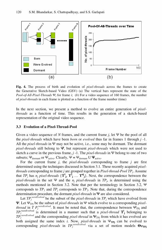
Fig. 4. The process of birth and evolution of pixel-threads across the frames to create the Generative Sketch-based Video (GSV) (a) The vertical bars represent the state of the Pool-of-All-Pixel-Threads Ψi for frame i; (b) For a video sequence of 160 frames, the number of pixel-threads in each frame is plotted as a function of the frame number (time)
In the next section, we present a method to evolve an entire generation of pixel-threads as a function of time. This results in the generation of a sketch-based representation of the original video sequence.
3.3 Evolution of a Pixel-Thread-Pool
Given a video sequence of N frames, and the current frame j, let Ψ be the pool of all the pixel-threads which have been born or evolved thus far in frames 1 through j -1. All the pixel-threads in Ψ may not be active, i.e., some may be dormant. The dormant pixel-threads still belong to Ψ, but represent pixel-threads which were not used to sketch a curve in the previous frame, j -1. The pixel-threads in Ψ belong to one of two subsets; Ψdormant or Ψactive. Clearly, Ψ = Ψdormant U Ψactive.
For the current frame j, the pixel-threads corresponding to frame j are first determined using the techniques discussed in Section 3.1. These recently acquired pixel-threads corresponding to frame j are grouped together in Pixel-thread-Pool TPj. Assume that TPj has nj pixel-threads {T1
j, T2j … Tnj
j}. Next, the correspondence between the pixel-threads in the set Ψ and the nj pixel-threads in TPj, is determined using the methods mentioned in Section 3.2. Note that per the terminology in Section 3.2, Ψ corresponds to TP1 and TPj corresponds to TP2. Note that, during the correspondence determination procedure, the dormant pixel-threads in Ψ are also considered.
Let TPjwereEvolved be the subset of the pixel-threads in TPj which have evolved from
Ψ. Let ΨTPj be the subset of pixel-threads in Ψ which evolve to a corresponding pixel-thread in T Pj
wereEvolved. It must be noted that, the correspondence between ΨTPj and TPj
wereEvolved is determined in a manner such that a pixel-thread Tij belonging to
TPjwereEvolved and the corresponding pixel-thread in ΨTPj from which it has evolved are
both assigned the same index i. Now, pixel-threads in ΨTPj can be evolved to corresponding pixel-threads in TPj
wereEvolved via a set of motion models ΘΨTPj
HLV Encoding for Mobile Internet-Based Computer Vision 121
(equation (4)). Since the remaining pixel-threads in TPij cannot be evolved from any
existing pixel-thread in Ψ, these pixel-threads are considered to belong to the set TPj
born; where TPjborn = TPj - TPj
wereEvolved. Next, the set Ψ is updated in the following manner:
(a) Pixel-threads in ΨTPj are evolved to corresponding pixel-threads in TPjwereEvolved,
using motion model parameters given by ΘΨTPj. The new pixel-threads in TPjborn are
included in Ψ. (b) The new set of active pixel-threads is given by Ψactive = Ψ ∩ TPj. These pixel-threads are used to generate the sketch-based representation of the new video frame. Naturally, the pixel-threads in this updated set Ψ, that have no counterparts in TPj, are deemed dormant; i.e.,
Ψdormant = Ψ - Ψactive
The data corresponding to frame j required to sketch the jth video frame are given by the motion model parameters denoted by ΘΨTPj. The newly born pixel-threads are included in TPj
born. Thus, the entire process of evolution of all the pixel-threads across all the N frames of the video can be effectively represented as a Generative Sketch-based Video (GSV), given by
A depiction of the process of evolution of the GSV is given in Fig 4(a). Fig 4(b) shows a plot of the total number of pixel-threads in Ψ as a function of time during the entire process of evolution of all the pixel-threads in the GSV representation of a sample video. The curve shows that, after the initial pixel-threads are created in the first frame, very few new pixel-threads are born thereafter. The initial pixel-threads are seen to be adequate to evolve and generate most of the entire GSV representation of the sample video.
Fig. 5. Flicker removal using the history of activity or dormancy of a pixel-thread. The encircled portion corresponds to a brief period of activity for the pixel-thread. The pixel-thread is made dormant to remove the flickering effect caused by this brief activity.
3.4 Flicker Reduction
When the pixel-threads for each frame are rendered, flickering effects are observed. This is due to the fact that some pixel threads appear momentarily in a frame, only to become dormant in a series of successive frames. The resulting sudden appearance and disappearance of pixel-threads creates a flickering effect. The All-Threads-Pool Ψ contains the list of all the dormant pixel-threads. When a pixel- thread, which is
122 S.M. Bhandarkar, S. Chattopadhyay, and S.S. Garlapati
dormant for some time, becomes active for a few frames, and then becomes dormant again, a flickering effect is observed. Thus, if such a pixel-thread is forced to be dormant instead of becoming active for a short time, the flickering effect is considerably reduced. The history of activity and dormancy is maintained for each pixel-thread in each frame, while the frame is being encoded. Once the entire video has been encoded, a second pass is made to determine, for each pixel-thread, the frames in which the pixel-thread should be made dormant, using the algorithm depicted in Fig 5.
4 Encoding the Texture - VTEXTURE
In the previous section, we described in detail how a Generative Sketch-based Video (GSV) is obtained from the original video. The GSV is used as the sketch component within the proposed HLV representation. In this section, we describe how the second component of HLV, i.e., the texture component, is created. The texture of the video, given by the component VTEXTURE, consists of three sub-components termed as Vorg, Vmid and Vbase where Vorg is the original video which is deemed to be of the highest visual quality, Vmid is the video of intermediate visual quality, and Vbase is the base-level video of the lowest visual quality. All the above video sub-components are encoded using the MPEG H.264 standard. In the interest of inter-operability, a deliberate effort has been made to incorporate within the proposed HLV encoding scheme, as many features of the MPEG H.264 standard as possible. In this section, we will discuss in detail the procedure for generation of each of the three layers.
4.1 Generating the Top-Most Video Layer Vorg
Vorg is the original video which is encoded efficiently using a state-of-the-art MPEG H.264 encoder that is available in the public domain [17]. A raw video encoded using the MPEG H.264 codec results in a very compact file representation. The MPEG H.264 codec uses inter-frame and intra-frame predictions to reduce significantly the spatial and temporal redundancy in the input video stream [8], [28].
4.2 Generating the Intermediate Video Layer Vmid
The video layer Vmid represents an intermediate-level video which has a more compact representation than the original video albeit at the cost of lower visual quality. It is a common observation that a lower-size video file leads to reduction in overall power consumption during the decoding process. The video layer Vmid is generated using a novel multi-resolution video encoding technique termed as Features, Motion and Object-Enhanced Multi-Resolution (FMOE-MR) video encoding [5]. The FMOE-MR video encoding scheme is based on the fundamental observation that applying a low pass filter in the image color space is equivalent to DCT coefficient truncation in the corresponding DCT (frequency) space [14]. The FMOE-MR video encoding scheme is a two step process as described in the following subsections.
HLV Encoding for Mobile Internet-Based Computer Vision 123
Generating the FMO-Mask. Instances of Features, Motion and Objects (FMOs) are detected in the video sequence using state-of-the-art computer vision algorithms. A corresponding mask, termed as an FMO-Mask, is created to mark the regions corresponding to the presence of the FMOs. The mask contains floating point values between (and inclusive of) 0 and 1, where 0 represents a completely uninteresting region and 1 represents a region that is vital for visual and semantic understanding of the image. The FMO-Mask is essentially a combination of one or more of the following three individual masks; the Feature-Mask (F-Mask), Motion-Mask (M-Mask) and the Object-Mask (O-Mask).
Feature-Mask (F-Mask): The Feature-Mask captures the important low-level spatial features of the video frame. Edges are one of the most important low-level features of an image (or video frame); since human perception tends to first detect edges for the purpose of object recognition and general scene analysis. Edges can be detected automatically in a given image or video frame. There are many ways to perform edge detection. However, the majority of different methods may be grouped into two broad categories: gradient-based and Laplacian-based. The gradient-based methods detect the edges by seeking a maximum in the magnitude of the first derivative of the image intensity (or color) function. The Laplacian-based methods, on the other hand, search for zero crossings in the second derivative of the image intensity (or color) function to detect and localize the edges. In our current work we have used the Canny edge detector [4] which is a gradient-based method to detect and localize the edges in a video frame. Once the edges in the video frame are detected and localized using the Canny edge detector, an F-Mask is created by assigning a value of 1 to regions in and around the edges, and the value of 0 elsewhere. Note that the mask is essentially a weighting matrix, where each pixel may be assigned a value between (and inclusive of), 0 and 1.
Motion-Mask (M-Mask): The motion within a video sequence constitutes a very important visual phenomenon since human perception of a dynamic scene tends to follow the moving objects and note their activities. Therefore, in situations which demand reduction in quality of the video, the image regions in the video that are characterized by significant motion can be rendered at high resolution and the remainder of the video frame at low resolution. A Motion-Mask (M-Mask) is obtained by identifying the regions within the video frames that contain moving objects. This is essentially accomplished via a process of background subtraction [7], [18], [19], [23], [24]. Background subtraction is performed typically by first creating (or learning) a background model for a video sequence. The video frames are then compared with the background model to detect regions which are not part of background. These regions are classified as belonging to the dynamic foreground, i.e., containing moving objects. Background subtraction thus allows one to extract foreground objects which are moving relative to the camera, or had been moving until recently. We used the background models described in [23], [24] to extract the dynamic foreground (i.e., the moving objects) from the background.
Object-Mask (O-Mask): All the foreground objects in a video sequence may not be equally important from a visual or semantic perspective. For example, in a video sequence containing a news reader with a rotating background logo, the face of the news reader is more important than the moving logo which, in the current implementation, is also considered part of the foreground. In this case, the face is
124 S.M. Bhandarkar, S. Chattopadhyay, and S.S. Garlapati
deemed an object of interest amongst the various foreground regions. Face detection and tracking is typically done by extracting feature points that characterize a face, and tracking these feature points in the video sequence. A detailed description of the face recognition and tracking algorithm is once again beyond the scope of this paper. In our current implementation, faces in a video sequence are detected using the algorithms described in [34], [35] and tracked using the algorithm described in [25] to create an O-Mask based on human faces automatically.
Combining F, M, O masks to form a single FMO-Mask: The three masks are superimposed to generate the final Features-Motion-Object-Mask (FMO-Mask). It is not always required to generate all the masks; for example, for a surveillance scenario, only the motion mask is required to capture the moving persons. Creation of the mask also depends on the computational resources available; the F-Mask and M-Mask can be typically generated in real time, and also combined in real time. When the resources available at the coding end are significantly constrained, only the F-Mask can be used since the edge detection procedure via the Canny edge detector is a task of low computational complexity.
Multi-Resolution (MR) re-encoding. The original frame is re-encoded as a multi-resolution (MR) representation, guided by the FMO-Mask such that regions corresponding to mask values close to 1 are at higher resolution than regions corresponding to mask values close to 0. The original video frame VO is used to render two video frames, VH and VL, such that VH is a high resolution rendering and VL is a low resolution rendering of VO. The video frames VL and VH are obtained by convolving VO with Gaussian filters characterized by the smoothing parameters σL and σH respectively. Maintaining σL > σH ensures that VL is smoother than VH, i.e., VL is a lower resolution rendering of VO than VH. If the FMO-Mask is represented as a matrix W whose elements lie in the range [0, 1], then the MR frame VMR is obtained via a linear combination of the two frames VH and VL as follows:
VMR = W • VH + (I − W) • VL
where I is a matrix all of whose elements are 1.
Fig. 6. Demonstration of the effect of Features, Motion and Object-enhanced Multi-Resolution (FMOE-MR) video encoding. (a) The original frame; (b) The FMO mask frame; (c) The frame re-rendered using FMOE-MR video encoding. Moving objects are rendered at high resolution whereas the background is rendered at low resolution. The obtained PSNR is 24.94.
HLV Encoding for Mobile Internet-Based Computer Vision 125
The values of σL and σH used to generate Vmid = VMR are selected empirically by the user. Empirical observations have revealed that σL = 9 or 11, and σH = 3, can be used, in most cases, to yield videos of reasonable visual quality with significantly smaller file sizes than the original video. Fig 6 presents an example of a video frame where the foreground moving object has been extracted using an FMO-mask. As is apparent, the regions where the moving objects are situated are rendered at higher resolution compared to the stationary regions comprising the background. Since an exhaustive treatment of the FMOE-MR video encoding scheme is beyond the scope of this paper, the interested reader is referred to [5] for further details. It must be noted that finally, Vmid too is encoded using the standard MPEG H.264 encoder, after preprocessing using FMOE-MR.
4.3 Generating the Base Video Layer Vbase
The base video layer Vbase is generated by first blurring each frame of the video using a Gaussian filter with smoothing parameter σbase prior to MPEG H.264 encoding. Note that this is similar to the Gaussian smoothing procedure performed in the case of FMOE-MR video encoding. The primary difference is that, in the case of the base video layer generation procedure, the smoothing is performed uniformly over the entire video frame in contrast to FMOE-MR video encoding where the extent of smoothing can vary within a video frame based on the perceptual significance of the region under consideration. This results in further dramatic decrease in the file size upon MPEG H.264 encoding, albeit at the loss of video quality. Note that Vbase is at of much lower visual quality than Vmid since object-based enhancement is not used. Vbase essentially serves to provide approximate color information for the Generative Sketch-based Video (GSV) representation described previously.
Fig. 7. The change in PSNR and file size of the video as a function of the Gaussian smoothing parameter σbase
4.4 Assessment of Visual Quality of VTEXTURE
The visual quality of each of the aforementioned video layers comprising VTEXTURE can be assessed in terms of PSNR values, as well as via subjective visual evaluation.
126 S.M. Bhandarkar, S. Chattopadhyay, and S.S. Garlapati
A quantitative evaluation of the average PSNR of a sample video with respect to the percentage decrease in video size is depicted in Fig 7. It is apparent that the video size can be decreased significantly by using a high value of σbase, albeit with a loss in video quality. We have observed empirically that values of σbase in the range [19, 25] can be used to generate the base video layer Vbase, resulting in a very small file size albeit at the cost of low resolution and low visual quality. However, approximate color information is still retained in the video layer Vbase, to the point that the visual quality of the resulting video improves significantly when the object outlines from the GSV representation are superimposed on the video layer Vbase. Fig 8 depicts the overall video encoding procedure. The specific HLV is generated by overlaying the sketch component VSKETCH over an appropriately chosen layer of VTEXTURE i.e., Vorg, Vmid or Vbase in our case. In the current implementation, the HLV encoding is done off-line. Consequently, the run times of the various procedures for generating the GSV and each of the texture layers Vorg, Vmid and Vbase are not very critical. Future work will focus on enabling real-time HLV encoding. In the next section, it is shown how different combinations of VSKETCH and VTEXTURE result in distinct video states where each video state has a characteristic resource consumption profile.
Fig. 8. The change in PSNR and file size of the video as a function of the Gaussian smoothing parameter σbase
HLV Encoding for Mobile Internet-Based Computer Vision 127
5 Encoding the Texture – VTEXTURE
As mentioned in the previous sections, the two components, VTEXTURE and VSKETCH, are obtained independently of each other. First, a suitable texture frame is extracted from the VTEXTURE component of the video by the video display controller. After this frame has been written to the frame buffer, the other component VSKETCH, is used to superimpose the object outlines on the frame buffer containing VTEXTURE. Note that both the aforementioned events are independent in terms of processing and are related only by order, i.e., VTEXTURE is rendered first, followed by the superimposition of VSKETCH on VTEXTURE. An example frame obtained by superimposing VSKETCH on the Vbase subcomponent of VTEXTURE is shown in Fig 9.
Fig. 9. An example demonstrating the combination of VSKETCH and VBASE
Let us suppose that the VTEXTURE component has L levels of resolution. In the current implementation, L = 4 which includes the three layers Vorg, Vmid and Vbase in decreasing order of visual quality and level 0 which denotes complete absence of texture information. Let Vj
TEXTURE (0 ≤ j ≤ L-1) correspond to the MPEG H.264-based encoding of the video where V0
TEXTURE denotes the complete absence of texture information, V1
TEXTURE denotes the video layer of the least visual quality and resolution (with deliberately induced loss in visual quality to ensure a very low bitrate and small video file size), and VL-1
TEXTURE denotes the video layer of the highest visual quality and resolution (i.e., the original video encoded using the MPEG H.264 standard with no deliberately induced loss in visual quality). Let the state of the HLV-encoded video be depicted as:
128 S.M. Bhandarkar, S. Chattopadhyay, and S.S. Garlapati
such that 0 ≤ texture-level ≤ L-1, and sketch-level ϵ {no-sketch, polyline-sketch, spline-sketch}. The above state-based representation allows for various resolutions of texture with superimposition of sketch-based representations of varying degrees of complexity. Under the above formalism, Γ(L, no-sketch) represents the original (i.e., best quality) video, and Γ(0, polyline-sketch) represents the video that contains no texture, but only the object outlines represented by polylines (presumably, the lowest quality video).
Furthermore, the states in the above representation are ordered linearly such that a “higher” video state is deemed to consume more resources (battery power and bandwidth) than a “lower” video state. Thus, it is essential to order the different states of the video in the above representation in terms of their resource consumption profiles. Let Resources(X, t) be the resource (battery time, bandwidth, etc.) estimate provided by the operating system on the playback device t seconds after the video playback has been initiated, where X denotes the state of the video during playback. Let Γ = {Γ1, …, ΓS} be the S distinct video states. We define a relation ≤p such that Γi ≤p Γj implies that
Resources(Γi, t) ≤ Resources(Γj, t), t > 0 (8)
In other words, the states are linearly ordered from left to right such that for any state (except for the terminal states Γ(L, no-sketch) and Γ(0, polyline-sketch)), the state on its left consumes fewer resources while decoding the entire video whereas the state on its right consumes more resources. The value Resources(Γcurrent-state, t) can be
Fig. 10. (a) State diagram depicting the state transition rules based on available residual battery time. The current state transitions to a higher state if the available residual battery time (Tbattery) is greater than the remaining running time of the video (Tvideo). Similarly, the current state transitions to a lower state if Tbattery < Tvideo. (b) The effect of video state transitions on the residual battery time. The video playback starts with Г(Vorg, no-sketch), changes state to Г(Vmid, no-sketch) then to Г(Vbase, spline-fit) and finally to Г(0, spline-fit). It is apparent that there is an improvement in the residual battery time every time a lower state is chosen.
HLV Encoding for Mobile Internet-Based Computer Vision 129
estimated using simple operating systems calls, which predict the remaining (residual) battery time or available bandwidth based on the current system load. Fig 10(a) depicts the state transition rules based on the available residual battery time. Fig 10(b) depicts the effect of the state transitions on the residual battery time on an IBM Thinkpad laptop PC with a 2 GHz Centrino Processor, 1 GByte RAM and 250 GByte hard disk running the video clip, a frame of which is depicted in Fig 6. It is clear that there is a significant improvement in the available residual battery time every time the system transitions to a state with lower resource consumption. Experimental results on a collection of 10 different video clips have shown that it is possible to save 45 minutes of battery capacity (energy) on average for the aforementioned IBM ThinkPad laptop PC by using the lowest layer of the proposed HLV representation, comprising only of the sketch component without any texture content, when compared to the reception and playback of the original video. Adding the approximated texture to the sketch component is observed to result in an average residual battery time savings of 30 minutes when compared to the reception and playback of the original video. The above experimental results serve to validate the claim that the proposed HLV representation does indeed result in different resource consumption estimates for distinct states in the aforementioned video state-based representation.
(a) (b) (c) (d)
Fig. 11. (a) Video frame from Γ6train (b) Result of background subtraction on Γ6
train (c) Video frame from Γ3
train (d) Result of background subtraction on Γ3train
6 HLV for Mobile Internet-Based Multimedia Applications
Note that the various video layers (or video states) in the proposed HLV encoding scheme are generated by altering the quality of the resulting encoded video. Since a video state in the proposed HLV encoding scheme is only an approximation to the original MPEG-encoded video, it raises a natural question, i.e., is the approximation good enough? Subjective evidence gathered from various human subjects has revealed that all the objects discernable in the MPEG-encoded video are also discernable in the HLV-encoded video. However, in the interest of objectivity, we have evaluated the proposed HLV encoding scheme in the context of some important multimedia applications in a resource-constrained mobile Internet environment, i.e., background subtraction, face detection, face tracking and face recognition, using quantitative performance metrics. Our current experiments are limited to the measurement of resource (battery power and bandwidth) consumption on the mobile end-user device on which the video is decoded and rendered. All experiments were performed on the aforementioned IBM Thinkpad laptop PC running in battery mode. In our future work, we intend to include other types of mobile devices such as PDAs, iPhones and pocket-PCs in our experiments.
130 S.M. Bhandarkar, S. Chattopadhyay, and S.S. Garlapati
6.1 Background Subtraction
As an objective comparison of HLV-encoded video quality, we used the videos corresponding to video states of the Train Station video, Γ3
train = Γ(Vbase, polyline-sketch), and Γ6
train = Γ(Vorg, null), to perform background subtraction. Note that Γ6train
= (Vorg, null), in our case, corresponds to the video with the highest visual quality. Background subtraction is the process of first estimating the background of the
Fig. 12. Video 1: Select frames from the face tracking experiment
Fig. 13. Video 2: Select frames from the face tracking experiment
(a) Video-1 (b) Video-2
(c) Video-3 (d) Video-4
Fig. 14. Comparison of face tracking error (in pixels) for different video layers
HLV Encoding for Mobile Internet-Based Computer Vision 131
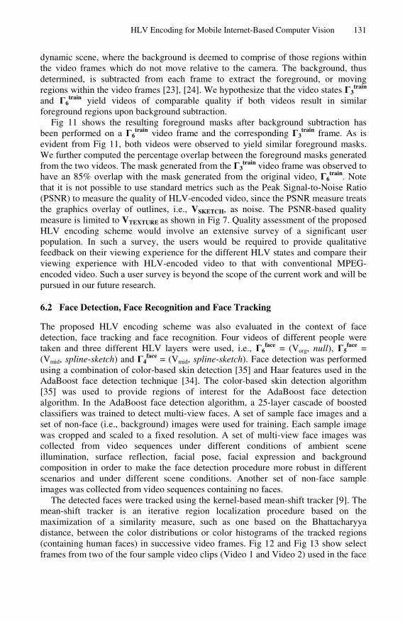
dynamic scene, where the background is deemed to comprise of those regions within the video frames which do not move relative to the camera. The background, thus determined, is subtracted from each frame to extract the foreground, or moving regions within the video frames [23], [24]. We hypothesize that the video states Γ3
train and Γ6
train yield videos of comparable quality if both videos result in similar foreground regions upon background subtraction.
Fig 11 shows the resulting foreground masks after background subtraction has been performed on a Γ6
train video frame and the corresponding Γ3train frame. As is
evident from Fig 11, both videos were observed to yield similar foreground masks. We further computed the percentage overlap between the foreground masks generated from the two videos. The mask generated from the Γ3
train video frame was observed to have an 85% overlap with the mask generated from the original video, Γ6
train. Note that it is not possible to use standard metrics such as the Peak Signal-to-Noise Ratio (PSNR) to measure the quality of HLV-encoded video, since the PSNR measure treats the graphics overlay of outlines, i.e., VSKETCH, as noise. The PSNR-based quality measure is limited to VTEXTURE as shown in Fig 7. Quality assessment of the proposed HLV encoding scheme would involve an extensive survey of a significant user population. In such a survey, the users would be required to provide qualitative feedback on their viewing experience for the different HLV states and compare their viewing experience with HLV-encoded video to that with conventional MPEG-encoded video. Such a user survey is beyond the scope of the current work and will be pursued in our future research.
6.2 Face Detection, Face Recognition and Face Tracking
The proposed HLV encoding scheme was also evaluated in the context of face detection, face tracking and face recognition. Four videos of different people were taken and three different HLV layers were used, i.e., Γ6
face = (Vorg, null), Γ5face =
(Vmid, spline-sketch) and Γ4face = (Vmid, spline-sketch). Face detection was performed
using a combination of color-based skin detection [35] and Haar features used in the AdaBoost face detection technique [34]. The color-based skin detection algorithm [35] was used to provide regions of interest for the AdaBoost face detection algorithm. In the AdaBoost face detection algorithm, a 25-layer cascade of boosted classifiers was trained to detect multi-view faces. A set of sample face images and a set of non-face (i.e., background) images were used for training. Each sample image was cropped and scaled to a fixed resolution. A set of multi-view face images was collected from video sequences under different conditions of ambient scene illumination, surface reflection, facial pose, facial expression and background composition in order to make the face detection procedure more robust in different scenarios and under different scene conditions. Another set of non-face sample images was collected from video sequences containing no faces.
The detected faces were tracked using the kernel-based mean-shift tracker [9]. The mean-shift tracker is an iterative region localization procedure based on the maximization of a similarity measure, such as one based on the Bhattacharyya distance, between the color distributions or color histograms of the tracked regions (containing human faces) in successive video frames. Fig 12 and Fig 13 show select frames from two of the four sample video clips (Video 1 and Video 2) used in the face
132 S.M. Bhandarkar, S. Chattopadhyay, and S.S. Garlapati
tracking experiment. Fig 14 (a)-(d) show the face tracking error for the different HLV layers on all four sample video clips where the layers Γ6
face, Γ5face and Γ4
face are denoted by HLV-6, HLV-5 and HLV-4 respectively. The tracking error in the case of Γ6
face (HLV-6) is indicative of the error introduced by the face detection and tracking algorithms and the basic MPEG encoding scheme. As can be seen from the plots for Γ5
face (HLV-5) and Γ4face (HLV-4) very little additional error is introduced by the
proposed HLV encoding scheme. As can be seen from Fig 14(a) and Fig 14(d), the tracking error values are almost similar for all three HLV layers under consideration. Note that the tracking error for each video frame is determined by computing the Euclidean distance between the centroid of the face region output by the face detection algorithm (in the first frame) or face tracking algorithm (in subsequent frames) and the centroid of the corresponding face region that is manually delineated. Video 1 and Video 4 are examples of video clips containing a single face whereas Video 2 and Video 3 contain multiple faces with significant scene clutter. On account of occlusion and scene clutter, the tracking error in Video 2 and Video 3 was observed to be significantly higher than that in Video 1 and Video 4.
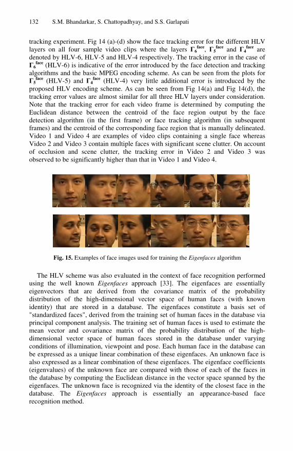
Fig. 15. Examples of face images used for training the Eigenfaces algorithm
The HLV scheme was also evaluated in the context of face recognition performed using the well known Eigenfaces approach [33]. The eigenfaces are essentially eigenvectors that are derived from the covariance matrix of the probability distribution of the high-dimensional vector space of human faces (with known identity) that are stored in a database. The eigenfaces constitute a basis set of "standardized faces", derived from the training set of human faces in the database via principal component analysis. The training set of human faces is used to estimate the mean vector and covariance matrix of the probability distribution of the high-dimensional vector space of human faces stored in the database under varying conditions of illumination, viewpoint and pose. Each human face in the database can be expressed as a unique linear combination of these eigenfaces. An unknown face is also expressed as a linear combination of these eigenfaces. The eigenface coefficients (eigenvalues) of the unknown face are compared with those of each of the faces in the database by computing the Euclidean distance in the vector space spanned by the eigenfaces. The unknown face is recognized via the identity of the closest face in the database. The Eigenfaces approach is essentially an appearance-based face recognition method.
HLV Encoding for Mobile Internet-Based Computer Vision 133
In our implementation, the face recognition system used a database of grayscale images scaled to 64 × 64 pixels with frontal profiles of 4 persons and 10 variations in pose, lighting and background conditions for each person. Fig 15 shows some of the faces used for training the Eigenfaces algorithm. The graph in Fig 16 compares accuracy of face recognition for each of the HLV layers under consideration, i.e., HLV-4, HLV-5 and HLV-6. The recognition accuracy was tested for varying ratios of the number of training images to the number of test images. All the training images were derived from the video layer HLV-6 whereas face recognition was performed on video frames derived from all the three HLV layers under consideration. As can be seen, the recognition accuracy decreases only slightly in the case of video layer HLV-4 whereas there is no major difference in face recognition accuracy between the video layers HLV-5 and HLV-6.
Fig. 16. Comparison of % accuracy in face recognition for different video layers
The above experimental results show that the proposed HLV encoding scheme is well suited for mobile Internet-based multimedia applications that are typically constrained by available resources, in particular, the available bandwidth and battery capacity of the mobile client device.
7 Conclusion
The increasing deployment of broadband networks and simultaneous proliferation of low-cost video capturing and multimedia-enabled mobile devices has triggered a new wave of mobile Internet-based multimedia applications. Applications such as Internet-based video on demand, community-based video sharing, and multimedia web services are no longer mere research ideas, but have resulted in several commercial products. However, mobile networked environments are typically resource constrained in terms of the available bandwidth and battery capacity on mobile devices. Multimedia applications that typically entail analysis, transmission, storage and rendering of video data are resource-intensive. Since the available bandwidth in the mobile Internet is constantly changing and the battery life of a mobile video capturing and rendering device decreases with time, it is desirable to have a video
134 S.M. Bhandarkar, S. Chattopadhyay, and S.S. Garlapati
representation scheme that adapts dynamically to the available resources. To this end we have proposed and implemented a Hybrid Layered Video (HLV) encoding scheme, which comprises of content-aware, multi-layer encoding of texture and a generative sketch-based representation of the object outlines. Different combinations of the texture- and sketch-based representations result in distinct video states, each with a characteristic bandwidth and power consumption profile.
The proposed HLV encoding scheme is shown to be effective for mobile Internet-based multimedia applications such as background subtraction, face detection, face tracking and face recognition on resource-constrained mobile devices. Future work will consider more advanced computer vision-based applications in a mobile Internet environment such as intelligent video surveillance, distributed gaming and human activity understanding. Our current experiments are limited to a single, potentially mobile device, i.e., an IBM Thinkpad laptop PC, with a 2 GHz Centrino CPU, 1 GByte RAM and 250 GByte hard disk, running in battery mode. We intend to include other types of mobile devices such as PDAs, iPhones and pocket-PCs in our future experiments. Our current experiments are also limited to the measurement of resource (battery power and bandwidth) consumption on the mobile end-user device on which the video is decoded and rendered. In our future work, we intend to investigate end-to-end computer vision systems and multimedia systems implemented in a mobile environment. This would involve a detailed study of both, resource consumption issues and mobile networking issues in each stage of the computer vision system or multimedia system dealing with acquisition, encoding, storage, indexing, retrieval, transmission, decoding and rendering of the video data. We also plan to perform a thorough quality assessment of the proposed HLV encoding scheme based on an extensive survey of a significant user population. In such a survey, the users would be required to provide qualitative feedback on their viewing experience for the different HLV states and compare their viewing experience with HLV-encoded video to that with conventional MPEG-encoded video. The aforementioned survey would serve to ascertain the superiority of the proposed HLV encoding scheme to the conventional MPEG encoding standard. In the current implementation, the HLV encoding is done off-line. Consequently, the run times of the various procedures for generating the GSV and each of the texture layers Vorg, Vmid and Vbase are not very critical. Future work will focus on enabling real-time HLV encoding.
References
1. Atallah, M.J.: Linear time algorithm for the Hausdorff distance between convex polygons. Information Processing Letters 17(4), 207–209 (1983)
2. Besl, P.J., Jain, R.: Segmentation through variable-order surface fitting. IEEE Trans. Pattern Analysis and Machine Intelligence 10(2), 167–192 (1988)
3. Bouguet, J.Y.: Pyramisdal Implementation of the Lucas Kanade Feature Tracker, Intel Corporation, Microprocessor Research Labs; included in the distribution of OpenCV
4. Canny, J.: A computational approach to edge detection. IEEE Trans. Pattern Analysis and Machine Intelligence 8(6), 679–698 (1986)
HLV Encoding for Mobile Internet-Based Computer Vision 135
5. Chattopadhyay, S., Luo, X., Bhandarkar, S.M., Li, K.: FMOE-MR: content-driven multi-resolution MPEG-4 fine-grained scalable layered video encoding. In: Proc. ACM Multimedia Computing and Networking Conference (ACM MMCN 2007), San Jose, CA, January 2007, pp. 650404.1–11 (2007)
6. Chattopadhyay, S., Bhandarkar, S.M., Li, K.: Ligne-Claire video encoding for power constrained mobile environments. In: Proc. ACM Multimedia, Augsburg, Germany, September 2007, pp. 1036–1045 (2007)
7. Cheung, S.-C., Kamath, C.: Robust background subtraction with foreground validation for urban traffic video. EURASIP Jour. Applied Signal Processing 14, 1–11 (2005); UCRL-JRNL-201916
8. Coding of Audio-Visual Objects, Part-2 Visual, Amendment 4: Streaming Video Profile, ISO/IEC 14 496-2/FPDAM4 (July 2000)
9. Comaniciu, D., Ramesh, V., Meer, P.: Kernel-based object tracking. IEEE Trans. Pattern Analysis and Machine Intelligence 25(5), 564–577 (2003)
10. Cornea, R., Nicolau, A., Dutt, N.: Software annotations for power optimization on mobile devices. In: Proc. Conf. Design, Automation and Test in Europe, Munich, Germany, March 2006, pp. 684–689 (2006)
11. Cucchiara, R., Grana, C., Prati, A., Vezzani, R.: Computer vision techniques for PDA accessibility of in-house video surveillance. In: Proc. ACM SIGMM International Workshop on Video Surveillance, Berkeley, CA, November 2003, pp. 87–97 (2003)
12. Dai, M., Loguinov, D.: Analysis and modeling of MPEG-4 and H.264 multi-layer video traffic. In: Proc. IEEE INFOCOM, Miami, FL, March 2005, pp. 2257–2267 (2005)
13. Davies, E.: Machine Vision: Theory, Algorithms and Practicalities, pp. 42–44. Academic Press, San Diego (1990)
14. Geusebroek, J.-M., Smeulders, A.W.M., Van de Weijer, J.: Fast anisotropic Gauss filtering. IEEE Trans. Image Processing 12(8), 938–943 (2003)
15. Hakeem, A., Shafique, K., Shah, M.: An object-based video coding framework for video sequences obtained from static cameras. In: Proc. ACM Multimedia, Singapore, November 2005, pp. 608–617 (2005)
16. Hennessy, J.L., Patterson, D.A.: Computer Architecture - A Quantitative Approach, 4th edn. Appendix D. Morgan Kaufmann, San Francisco (2007)
17. http://www.squared5.com 18. Ivanov, Y., Bobick, A., Liu, J.: Fast lighting independent background subtraction.
International Journal of Computer Vision 37(2), 199–207 (2000) 19. Javed, O., Shafique, K., Shah, M.: A hierarchical approach to robust background
subtraction using color and gradient information. In: Proc. IEEE Workshop on Motion and Video Computing, Orlando, FL, December 2002, pp. 22–27 (2002)
20. Khan, S., Shah, M.: Object based segmentation of video using color motion and spatial information. In: Proc. IEEE Conf. Computer Vision and Pattern Recognition, Kauai Island, HI, December 2001, vol. 2, pp. 746–751 (2001)
21. Ku, C.-W., Chen, L.-G., Chiu, Y.-M.: A very low bit-rate video coding system based on optical flow and region segmentation algorithms. In: Proc. SPIE Conf. Visual Communication and Image Processing, Taipei, Taiwan, May 1995, vol. 3, pp. 1318–1327 (1995)
22. Liang, C., Mohapatra, S., Zarki, M.E., Dutt, N., Venkatasubramanian, N.: A backlight optimization scheme for video playback on mobile devices. In: Proc. Consumer Communications and Networking Conference (CCNC 2006), January 2006, vol. 3(2), pp. 833–837 (2006)
136 S.M. Bhandarkar, S. Chattopadhyay, and S.S. Garlapati
23. Luo, X., Bhandarkar, S.M.: Robust background updating for real-time surveillance and monitoring. In: Proc. Intl. Conf. Image Analysis and Recognition, Toronto, Canada, September, 2005, pp. 1226–1233 (2005)
24. Luo, X., Bhandarkar, S.M., Hua, W., Gu, H., Guo, C.: Nonparametric background modeling using the CONDENSATION algorithm. In: Proc. IEEE Intl. Conf. Advanced Video and Signal-based Surveillance (AVSS 2006), Sydney, Australia, November 2006, pp. 13–18 (2006)
25. Luo, X., Bhandarkar, S.M.: Tracking of multiple objects using optical flow-based multiscale elastic matching. In: Vidal, R., Heyden, A., Ma, Y. (eds.) WDV 2005/2006. LNCS, vol. 4358, pp. 203–217. Springer, Heidelberg (2007)
26. Mohapatra, S., Cornea, R., Dutt, N., Nicolau, A., Venkatasubramanian, N.: Integrated power management for video streaming to mobile handheld devices. In: Proc. ACM Multimedia, Berkeley, CA, November 2003, pp. 582–591 (2003)
27. Ni, P., Isovic, D., Fohler, G.: User-friendly H.264/AVC for remote browsing. In: Proc. ACM Multimedia, Santa Barbara, CA, October 2006, pp. 643–646 (2006)
28. Richardson, I.E.G.: H.264 and MPEG-4 Video Compression: Video Coding for Next Generation Multimedia. Wiley, New York (2004)
29. Rosin, P.L., West, G.A.W.: Non-parametric segmentation of curves into various representations. IEEE Trans. Pattern Analysis and Machine Intelligence 17(12), 1140–1153 (1995)
30. Salembier, P., Marques, F., Pardas, M., Morros, J.R., Corset, I., Jeannin, S., Bouchard, L., Meyer, F., Marcotegui, B.: Segmentation-based video coding system allowing the manipulation of objects. IEEE Trans. Circuits and Systems for Video Technology 7(1), 60–74 (1997)
31. Salomon, D.: Data Compression: The Complete Reference. Springer, Berlin (2004) 32. Sikora, T.: Trends and perspectives in image and video coding. Proc. IEEE 93(1), 6–17
(2005) 33. Turk, M., Pentland, A.: Eigenfaces for recognition. Jour. Cognitive Neurosicence 3(1), 71–
86 (1991) 34. Viola, P., Jones, M.: Rapid Object Detection using a Boosted Cascade of Simple Features.
In: Proc. IEEE Conf. Computer Vision and Pattern Recognition, Kauai Island, HI, December 2001, vol. 1, pp. 511–518 (2001)
35. Zarit, B.D., Super, B.J., Quek, F.K.H.: Comparison of five color models in skin pixel classification. In: Intl. Workshop on Recognition, Analysis, and Tracking of Faces and Gestures in Real-Time Systems, Washington, DC, September 1999, pp. 58–63 (1999)