1372 T. Prosin et al. / Energy Procedia 69 ( 2015 ) 1371 – 1381
Keywords: CST, CSP, hybrid, particel receiver, CentRec, solar tower, coal
1. Introduction
This paper will compare conventional steam cycle hybridisation by TBS heating with the proposed more efficient air preheating option [1] using thermodynamic modelling on an annual basis. The CST technology most appropriate for air-side solar hybridization must be capable of achieving high temperatures because the solar to electricity conversion efficiency increases with temperature, as does the solar share. If a large solar share is to be included in the plant design there will need to be adequate thermal storage. Thermal storage is necessary for stable plant operation and to control energy dispatchability to accommodate the variability in the solar resource and minimise combustion ramp rates within the boiler. A solar system with incorporated energy storage will significantly decrease the annual fuel requirement, as solar operation hours and capacity factor (CF) can be significantly increased. A recently developed solid particle receiver, CentRec system [2], appears to meet the requirements for stable and efficient hybridization of a coal fired power station.
Nomenclature
CentRec Centrifugal Receiver HHV Higher heating value LHV Lower heating value Q Thermal energy SPR Solid Particle Receiver TBS Turbine Bleed Steam X Solar share Subscripts a annual am amortised c coal inc incident m mass flow rate (fuel / coal) ref reference plant configuration s solar t total th thermal
2. Solid particle receiver system
A solid particle receiver (SPR) system uses heat resistant and robust ceramic particles as a heat transfer medium to directly absorb incident solar radiation. The receiver system can achieve very high efficiencies by absorbing very high solar flux densities due to the high mass flow of the heat transfer medium through the receiver. During operation, solar radiation is reflected and concentrated from a field of sun tracking mirrors (heliostats) onto the particle receiver located at the top of a tower. Once heated, these particles can be transported to an insulated high temperature storage vessel, where the hot particles are used directly as the thermal storage medium. Air can be heated in a counter-current moving bed direct contact heat exchanger from the hot particles by blowing air through the hot particles as they are transferred to a second storage vessel (for low temperature storage at several hundred degrees). The heat transfer can be quite efficient as the particle flow has a large surface area, so a difference between air and particle temperature after heat exchange lower than 50 K is expected. After the particles have been cooled, they are transported back to the receiver, at the top of the tower using a lift system. Fig. 1 depicts the basic operation of the solar particle receiver cycle.
T. Prosin et al. / Energy Procedia 69 ( 2015 ) 1371 – 1381 1373
Fig. 1. Centrifugal particle receiver operation
2.1. Centrifugal particle receiver concept
The CentRec, developed by the DLR, operates by exposing solid particles directly to solar radiation. The cylindrical cavity receiver rotates and the resultant centripetal force on the particles cause them to form a covering layer on the internal receiver wall. The resultant friction force slows the particles decent through the receiver which increases the exposure time to the incoming solar radiation. Varying the rotation speed allows control of the particle flow rate and allows adaptation of the mass flow to actual solar power input, ensuring a high constant outlet temperature. Fig. 2 depicts the basic operation principle of the experimentally verified CentRec [2] concept.
A reference model of an existing coal fired steam power plant was created so that the effectiveness of several solar hybridisation methods could be modelled on the same reference model. The reference model was calibrated as closely as possible against the real power plant.
3.1. Reference power plant
The steam power plant investigated by the model was based on a typical supercritical steam power plant resembling the 750 MWe Kogan Creek black coal plant (located in Chinchilla, Australia) with reheat and cycle
1374 T. Prosin et al. / Energy Procedia 69 ( 2015 ) 1371 – 1381
parameters 250/60 bar and 540°C/560°C [3, 4]. A schematic of the plant layout is shown in Fig. 3 and features 7 bleed steams and 8 feedwater heaters (3 high pressure heaters (HPHs), 4 low pressure heaters (LPHs) and a deaerator) and a condenser.
The design limit of the actual Kogan Creek turbine is stated to be 781 MWe gross, while standard operation is
744 MWe gross [3, 5]. The net output of the plant in nominal operation is 95% of the gross power [4]. While it is stated in public documentation that the Kogan Creek solar booster provides a 44 MWe net solar-boost [6, 7], other sources suggest that only a 37 MWe gross boost is realised [5]. This difference is probably due to the parasitic energy demand of the high pressure feedwater pump and may be reduced in operation if the solar field installation is larger than required for the turbine boost and re-circulating steam flow to the feedwater pump/turbine. Installation of a solar field to accomplish this parasitic reduction can be done at any time and in combination with any solar augment option, therefore we ignored this option in the study. In the actual installation the maximum solar-boost power is limited by the design limit of the turbine. The solarisation options presented in this paper are designed for fuel saving mode (same output with less fuel) rather than solar booster mode (increasing output) so that the solar share is not restrained by the design limits of the turbine, thereby providing a fair comparison between solarising methods.
In order to model accurately the effect of solarisation on the power cycle and boiler of a coal fired power station,
a powerful thermodynamic cycle analysis tool was needed. EBSILON®Professional was chosen because of its flexibility and level of detail. The first step was to create a representative model of the plant. Two available heat balance diagrams (HBDs) of the solar-boosted (more output with same fuel use) Kogan Creek plant were created to provide steam conditions at critical points in the cycle and give the efficiencies of the turbine stages during solar-boosting [7, 8]. The next step adjusted the plant to its unboosted state, the mass flow to the existing solar field was shut off, and the model parameters were calibrated so that the available performance data of the non-boosted plant and those of the boosted plant were met. The fuel composition of Queensland coal with heating value 30 MJ/kg was provided in the Ebsilon software. Variation of the ambient conditions was neglected, and maintained at 101.3 kPa and 25°C. The final modelled power cycle HBD is presented in Fig. 3, including the modelled boiler.
Fig. 3 Heat balance diagram of supercritical coal fired power plant showing solar SPR air-preheating and TBS solarisation points. For TBS solarisation, the solar to electric conversion efficiency of solar energy is limited by the steam conditions
(temperature and pressure) at the solar steam injection point. According to the available HBDs the solar
T. Prosin et al. / Energy Procedia 69 ( 2015 ) 1371 – 1381 1375
hybridisation option for the Kogan Creek solar boosted power station supplies bleed steam at roughly 335°C to the cold reheat integration point. It does this using steam generated by water flow from the feedwater tank situated before the final two HPHs. For TBS solarisation at these temperatures, this is the most efficient solarisation point [9]. To compare the TBS solarisation option used in the Kogan Creek plant to a solar air preheating solarisation option at the same plant a model to represent a typical Benson once-through supercritical boiler was required to enable the full power plant simulation, as the solar field input is ‘injected’ at the boiler.
3.2. Boiler model
The boiler model was calibrated for a typical arrangement of superheat and reheat surfaces [10] to match realistic conditions for a boiler operating with live steam conditions of 540°C and 250 bar [11], with feedwater and spray attemperation. The layout was adjusted to approximate the design temperatures of both the flue gas and water/steam of an existing boiler at the inlet and outlet of the superheaters, as well as the re-heaters and economiser [12]. Secondary air enters the boiler from ambient, and is heated in the air pre-heater, by heat exchange with exhaust flue gasses to around 280°C. This air is further heated by hot particles SPR outlet temperature. The preheated secondary air then joins with a pulverised coal/primary air mixture and is combusted. As approximately 80% of the air combusted comes from the secondary air stream, raising the temperature of secondary air can dramatically reduce fuel requirements. After combustion, the flue gas stream is cooled by feedwater and steam at the evaporator, superheaters and economiser (a portion of the heat can be re-circulated to the pre-solarisation/combustion air stream). The main air stream then undergoes de-noxification, cooling at the air pre-heater, de-sulphurisation and filtering then finally venting to the atmosphere via the stack at ~150°C, exceeding the sulphur dew point.
3.3. Solar system modelling
The CST plants was simulated at the same location as the Kogan Creek Power station (Chinchilla QLD 26.8°S and 150.6°E), using an hourly DNI data of an average year in terms of solar resource [13] at the site (2006.3 kWh/m2a).
3.4. Fresnel system model
The US NREL-SAM software, a general purpose CST system modelling software, was selected to calculate the annual efficiency and output of a modern Linear Fresnel solar collector. A SAM saved model file from the public resource of system files specifically created for Linear Fresnel systems and Australian conditions [13], was loaded and then altered to approximate the parameters of the Kogan Creek HBD bleed steam generation conditions (once through boiler model, with 335°C output). The SAM saved file was created based on Novatec Solar’s guaranteed key performance indicators which are used as a basis for contractual agreements.
As the Fresnel system simulated did not require a redesign so no cost parameters were required for optimisation. However, in order to calculate the energy cost of the Fresnel hybridisation, the overall project cost totalling $AU 104.7 million was needed [14] for a 125 MWth [15] solar field (specific cost of 838 $/kWth solar field). It was assumed that operations and maintenance (O&M) costs amount to around 2.75% of capital expenditure (CAPEX) [16], and that 80% of project costs were direct CAPEX.
3.5. Particle receiver system model
A quasi-dynamic simulation environment was used to obtain the annual energy yield of a simulated heliostat-tower CST system based on a particle receiver. The simulation environment includes the ability to economically optimise the system for lowest energy cost. The optical performance of the solar field was calculated using the DLR software HFLCal [17] while thermodynamic relationships and supplier information were used to model thermal and other performance losses at every macro-component of the system. The CentRec receiver model was developed using simulation tools and results from DLR experimental results [2]. The costs used in the system design and optimisation are shown in Table 1. They are within the range of possible costs for the critical components developed
1376 T. Prosin et al. / Energy Procedia 69 ( 2015 ) 1371 – 1381
from manufacturer data for a first demonstration system [18], as well as expected serial production costs of the components.
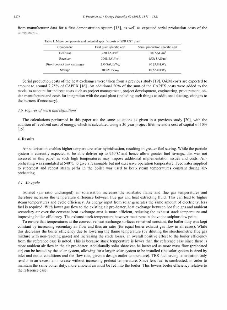
Table 1. Major components and potential specific costs of SPR CST plant
Component First plant specific cost Serial production specific cost
Heliostat 250 $AU/m2 100 $AU/m2
Receiver 300k $AU/m2 150k $AU/m2
Direct contact heat exchanger 250 $AU/kWth 80 $AU/kWth
Storage 30 $AU/kWth 10 $AU/kWth
Serial production costs of the heat exchanger were taken from a previous study [19]. O&M costs are expected to
amount to around 2.75% of CAPEX [16]. An additional 20% of the sum of the CAPEX costs were added to the model to account for indirect costs such as project management, project development, engineering, procurement, on-site manufacture and costs for integration with the coal plant (including such things as additional ducting, changes to the burners if necessary).
3.6. Figures of merit and definitions
The calculations performed in this paper use the same equations as given in a previous study [20], with the addition of levelized cost of energy, which is calculated using a 30 year project lifetime and a cost of capital of 10% [15].
4. Results
Air solarisation enables higher temperature solar hybridisation, resulting in greater fuel saving. While the particle system is currently expected to be able deliver up to 950°C and hence allow greater fuel savings, this was not assessed in this paper as such high temperatures may impose additional implementation issues and costs. Air-preheating was simulated at 540°C to give a reasonable but not excessive operation temperature. Feedwater supplied to superheat and reheat steam paths in the boiler was used to keep steam temperatures constant during air-preheating.
4.1. Air-cycle
Isolated (air ratio unchanged) air solarisation increases the adiabatic flame and flue gas temperatures and therefore increases the temperature difference between flue gas and heat extracting fluid. This can lead to higher steam temperatures and cycle efficiency. As energy input from solar generates the same amount of electricity, less fuel is required. With lower gas flow to the existing air pre-heater, heat exchange between hot flue gas and ambient secondary air over the constant heat exchange area is more efficient, reducing the exhaust stack temperature and improving boiler efficiency. The exhaust stack temperature however must remain above the sulphur dew point.
To ensure that temperatures at the convective heat exchange surfaces remained constant, the boiler duty was kept constant by increasing secondary air flow and thus air ratio (for equal boiler exhaust gas flow in all cases). While this decreases the boiler efficiency due to lowering the flame temperature (by diluting the stoichiometric flue gas mixture with non-reacting gases) and increasing the stack losses, an overall positive effect to the boiler efficiency from the reference case is noted. This is because stack temperature is lower than the reference case since there is more ambient air flow in the air pre-heater. Additionally solar share can be increased as more mass flow (preheated air) can be heated by the solar system, allowing for a larger solar system to be installed (the solar system is sized by inlet and outlet conditions and the flow rate, given a design outlet temperature). TBS fuel saving solarisation only results in an excess air increase without increasing preheat temperature. Since less fuel is combusted, in order to maintain the same boiler duty, more ambient air must be fed into the boiler. This lowers boiler efficiency relative to the reference case.
T. Prosin et al. / Energy Procedia 69 ( 2015 ) 1371 – 1381 1377
4.2. Re-circulation of flue gasses
Re-circulation of flue gas is used in conventional coal plants [21] to improve boiler performance [22]. Air solarisation enables greater re-circulation as combustion can take place at higher air ratios, as described in section 4.1. If the boiler system does not already include a re-circulation loop, a cost-benefit analysis of the blower and air ducting costs against performance improvement must be made before such a re-circulation loop would be retrofitted.
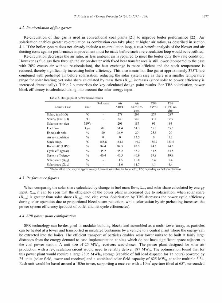
Re-circulation decreases the air ratio, as less ambient air is required to meet the boiler duty flow rate condition. However as flue gas flow through the air pre-heater with fixed heat transfer area is still lower (compared to the case with 20% excess air without re-circulation), the heat exchange is more efficient and the stack temperature is reduced, thereby significantly increasing boiler efficiency. This also means hot flue gas at approximately 375°C are combined with preheated air before solarisation, reducing the solar system size as there is a smaller temperature range for solar heating; yet solar share calculated by mass flow (Xs, ) increases (since solar to power efficiency is increased dramatically). Table 2 summarises the key calculated design point results. For TBS solarisation, power block efficiency is calculated taking into account the solar energy input.
Table 2. Design point performance results
Result / Case
Unit
Ref. case Air 540°C
Air 540°C re-
circ.
TBS 335°C
TBS 335°C re-
circ. Solarin (air/H2O) °C - 278 299 279 287 Solarout (air/H2O) °C - 540 540 335 335 Solar system size MWth - 201 187 95 95 Fuel flow kg/s 58.1 51.4 51.3 55.7 55.5 Excess air ratio % 20 36.9 20 25.5 20 Air re-circulation % 0 0 13.5 0 5.2 Stack temp. °C 155.8 154.1 149.9 155.2 153.6 Boiler eff. (LHV) % 94.4 94.5 95.3 94.2 94.6 Cycle eff. (gross) % 45.2 45.2 45.2 44.5 44.5 System efficiency % 40.4 40.5 40.9 39.8 39.9 Solar share (Xs,Q) % - 11.5 10.8 5.4 5.4 Solar share (Xs, ) % - 11.6 11.7 4.1 4.4
*Boiler eff. (HHV) may be approximately 5 percent lower than the boiler eff. (LHV) depending on fuel specifications
4.3. Performance figures
When comparing the solar share calculated by change in fuel mass flow, Xs, , and solar share calculated by energy input, Xs,Q, it can be seen that the efficiency of the power plant is increased due to solarisation, when solar share (Xs, ) is greater than solar share (Xs,Q), and vice versa. Solarisation by TBS decreases the power cycle efficiency during solar operation due to proportional bleed steam reduction, while solarisation by air-preheating increases the power system efficiency (product of boiler and net cycle efficiencies).
4.4. SPR power plant configuration
SPR technology can be designed in modular building blocks and assembled as a multi-tower array, as particles can be heated at a tower and transported in insulated containers by a vehicle to a central plant where the energy can be extracted into the boiler. The efficient transport of particles enables solar tower units to be built at fairly large distances from the energy demand to ease implementation at sites which do not have significant space adjacent to the coal power station. A unit size of 25 MWth receivers was chosen. The power plant designed for solar air production with a re-circulation circuit would need to reliably deliver 187 MWth. The optimisation found that for this power plant would require a large 2805 MWhth storage (capable of full load dispatch for 15 hours) powered by 25 units (solar field, tower and receiver) and a combined solar field capacity of 625 MWth at solar multiple 3.34. Each unit would be based around a 105m tower, supporting a receiver with a 10m2 aperture tilted at 65°, surrounded
1378 T. Prosin et al. / Energy Procedia 69 ( 2015 ) 1371 – 1381
by 39 000 m2 of reflective mirror area (36 m2 heliostats). Fig. 4 depicts the layout of a single solar tower module, which encompasses a circle with a 350m diameter, and 95 000 m2 area.
Fig.4 Solar field layout with annual heliostat efficiency (incl. spillage) – 25 MWth receiver capacity (optimised aperture to 10m2)
Due to the optimisation target of lowest thermal energy cost and the receiver’s ability to handle very high solar flux densities due to direct absorption of concentrated solar flux within the solid particles, a cost optimisation resulted in an unusually high 2.5 MWth/m2 average flux density over the aperture. While this results in additional spillage losses (radiation lost due to missing the receiver aperture) the high density results in a high receiver efficiency of 95.4% peak and 92% annual, but most importantly, resulting in a cost optimal solution for the multi-tower system.
The combined cost of the ‘first plant’ SPR project was calculated to $AU 591 million, including an additional
20% of CAPEX costs for implementation, project development, engineering procurement and construction and contingencies. This is a specific cost of $3160/kWth which includes a 15 hour thermal energy storage. The relative cost contributions of the main expenditures are shown in Fig. 5 where it is clear that in comparison to stand alone systems, the hybridized CentRec system CAPEXs are significantly solar field related. Further cost reduction in heliostat costs would be especially beneficial to this system.
Fig.5 Predicted CAPEX breakdown of CentRec hybridization project
Solar fields 50%
Receivers 15%
Towers 4%
Storage 17%
Particle DC heat
exchangers 9%
Lifts + horizontal transport
5%
Project CAPEX Breakdown
T. Prosin et al. / Energy Procedia 69 ( 2015 ) 1371 – 1381 1379
4.5. Annual results
While design point results are useful in understanding a system, figures of merits for energy system comparisons are only valid on an annual basis. Therefore the annual solar performance, which is affected by the operating temperature of the solar receiver, and respectively the thermal storage if applicable, must be known. Annual solar to thermal efficiencies for the assessed technology options are shown in Table 3. Table 4 outlines capacity factors (CF) for the systems assessed in this study.
Table 3. Approximate annual solar to thermal efficiency at varying receiver outlet conditions in Chinchilla.
Technology / Outlet Temperature 335°C 540°C Solar tower particle receiver with storage (SM=3.34) - 50.2% Linear Fresnel DSG (SM=1.1) 40.0% -
Table 4. Approximate annual solar to thermal energy capacity factors at varying receiver outlet conditions in Chinchilla.
Technology / Outlet Temperature 335°C 540°C Solar tower particle receiver with storage (SM=3.34) - 66.8% Linear Fresnel DSG (SM=1.1) 15.3% -
The quoted thermal CF of the Fresnel Kogan Creek solar booster system is 11.5% [7, 21]. The higher simulated
result suggest that in reality there may be availability issues due to difficulties in regulating steam conditions without storage (given a fluctuating solar resource), as TBS solarisation steam must closely match the cycle TBS conditions.
Table 5. Figures of merit (annual)
Annual result / Case Unit Ref. case
Air 540°C Air 540°C re-circ.
TBS 335°C TBS 335°C re-circ.
Solar share (Xs, ) % - 7.7 7.8 0.66 0.72 Solar to el. eff. % - 20.4 22.3 12.8 13.9
a) all annual results are given for net total plant (LHV), combining boiler and turbine/cycle
Table 5 shows that solarisation by air preheating with a SPR system can potentially be significantly more effective than the current method. It should be noted that even though the air system with flue gas re-circulation has a smaller capacity, the solar share is calculated to be higher due to the amount re-circulation improves the conversion efficiency.
4.6. Energy costs
The annual solar electrical production by the Linear Fresnel system was calculated to be 44.2 GWhe, while the solar electrical production of the CentRec system was 486 GWhe. This meant that the simulated CentRec tower system even had a better land use efficiency (1.2 Acres/GWhe) than the actual Kogan Creek Fresnel station [14] (1.7 Acres/GWhe), despite the SPR system also incorporating an energy storage providing additional benefits. Table 6 shows the energy costs of the compared hybridising methods. The range of uncertainty in the calculated energy cost of the CentRec system due to uncertainties in cost and performance may be in the range ±20%.
Table 6. Levelized cost of solar electricity [$AU/MWhe] (gross solar)
Technology Fresnel TBS solar hybrid CentRec air-solar hybrid First Demo. Project 266 157 Mature Technology - 70
Since the cycle efficiency is decreased by the TBS hybridisation, the poorer performance is naturally
incorporated in the calculation of electricity production by the TBS system (and is represented in the cost of solar electricity). If this was not the case, the TBS hybridisation would increase the cost of coal produced electricity even
1380 T. Prosin et al. / Energy Procedia 69 ( 2015 ) 1371 – 1381
if the solar plant had no cost. This results in higher solar electricity costs than a stand-alone Fresnel plant in some cases. For the cost assumptions used in this study, even the first generation CentRec SPR system utilised for air hybridisation of a coal power station is predicted to have significantly lower costs than the currently utilised TBS method with Fresnel collectors. Furthermore, calculating with the predicted component costs for serial production of CentRec systems, the cost of electricity produced from air hybridisation with a CentRec CST plant is in the range of the cost of coal produced electricity in some cases without any government subsidies. Furthermore, the CentRec system not only saves significantly more fuel in the year (almost 11 times more fuel saved per year) but has the added benefit of containing a full 15h thermal storage. Extended operation of the storage based system ensures reliable and controlled energy dispatch and predictable operation of the hybrid system. The energy cost is given in gross solar, which means that parasitic energy demand to operate the solar systems, such as solar field tracking, pumping and lift motors, have not been included. The total parasitic demand of the CentRec system was calculated to around 4.2% of produced electricity, which is not significantly more than what is expected for a CST plant. The blower at the heat exchanger and lift system were more responsible for the parasitic demand than the solar field.
5. Conclusion and summary
Solarisation by TBS led to a reduced power cycle efficiency, while solarisation by air-preheating increases the power cycle performance. The improvement in cycle performance from air-preheat solar hybridisation was due to an increase in boiler efficiency. This is a benefit that could not be achieved otherwise even for equivalent temperature main steam solar integration. Due to a more efficient system operation and the addition of efficient and low cost thermal storage provided by solid particle CentRec based solar towers, significantly greater annual fuel savings can be made. These savings increase the 0.7% annual fuel saving using the current method of TBS solarisation to almost 8% using SPR solar air-hybridisation at 540°C. In a previous study SPR solar air-hybridisation up to 950°C has been calculated to save 20% of the annual fuel use [20]. While the air-solar system size was calculated to be up to 187 MWth with a 15 hour storage, a SPR module can be installed with much lower power ratings (as small as 1 MWth) operating at a similar solar-thermal efficiency. This could allow deployment of a demonstration system at minimal cost.
Air solarisation of a coal power plant by CentRec technology enables notably higher annual solar to electricity
conversion efficiency compared to the linear Fresnel option assessed, due in part to the high annual receiver efficiency of 92%. Perhaps most interestingly, it was calculated that the levelized cost of the solar electricity produced by a first of its kind CentRec SPR system was approximately 59% of the electricity produced by the Fresnel hybrid option. Furthermore, the predicted cost of solar electricity produced from a CentRec SPR air hybrid coal plant with serial production of the core components at $70 AU/MWhe could mean the technology could be competitive with coal produced electricity under certain circumstances. This shows great promise for both hybridisation of air-preheat hybridisation and the economic performance of the CentRec technology. Further work is needed to quantify and evaluate the commercial opportunity of the mature SPR technology with respect to coal pricing and potential market size, for air-preheat solar hybridisation of coal power stations in the Australian energy market.
Acknowledgement
This project has been supported by the Australian Government through the Australian Renewable Energy Agency (ARENA). Responsibility for the views, information or advice expressed herein is not accepted by the Australian Government. Further gratitude is appreciatively extended to Hans-Peter Wolf for the invaluable technical support required for the Ebsilon cycle model creation.
T. Prosin et al. / Energy Procedia 69 ( 2015 ) 1371 – 1381 1381
References
[1] Deng, S., Hybrid Solar and Coal-Fired Steam Power Plant Based on Air Preheating, Journal of Solar Energy Engineering, 136, 2014. [2] Wu, W., Amsbeck, L., Buck, R., Uhlig, R., Pitz-Paal, R., Proof of concept test of a Centrifugal Particle Receiver, Proc. SolarPACES 2013,
Las Vegas, USA, September 2013. [3] Cziesla, F., Kremer, H., Much, U., Riemschneider, J., Quinkertz, R., Advanced 800+ MW Steam Power Plants and Future CCS Options, Proc.
Coal-Gen Europe 2009, Katowice, Poland, September 1-4, 2009. [4] Modern Power Systems, 2006, Kogan Creek enters the commissioning phase, retrieved 2014, from
<http://www.modernpowersystems.com/features/featurekogan-creek-enters-the-commissioning-phase/>. [5] Australian Energy Market Operator, 2014, Electricity Registration and Exemption List, retrieved January 2014, from
<http://www.aemo.com.au/Electricity/Registration>. [6] CS Energy 2013, CS Energy Annual Report 2012/2013, CS Energy Limited, Brisbane. [7] CS Energy, 2014, Kogan Creek Solar Boost Project, retrieved November 2013, from <http://kogansolarboost.com.au/about/>. [8] Richardson, I., Kerr, B., Rawlings, I., Doucet, D., Chapman, L., Joy, G., CS Energy’s Kogan Creek Power Station Chemistry Experience,
2012, retrieved 2013, from <http://acc-usersgroup.org/wp-content/uploads/2011/02/KoganCreek-2010-ACC.pdf>. [9] Siros, F., Philibert, C., Le Moullec, Y., Tusseau, M., Bonnelle, D., The Value of Hybridising CST, Proc. SolarPACES 2012, Marrakesh,
Morocco, September 2012. [10] Venetos, M., Conlon, W., Solar Steam Boosters for Coal-fired Power Plants, Power Engineering, volume 114, issue 11, November 2010,
retrieved October 11, 2013, from <http://www.power-eng.com/articles/print/volume-114/issue-11/features/solar-steam-boosters-for-coal-fired-power-plants.html>.
[11] Kumar, R., Talukdar, P., Subbarao, P., CFD Analysis of Flue Gas Ducts of 500 MW Pulverized coal Boiler, Proc. ISHMT-ASME, January 4-6, 2010, IIT Mumbai, India.
[12] Subbarao, P., Final Audit: Utilization of Flue Gas Energy, Mechanical Engineering Department Indian institute of technology Dehli 2011, retrieved December 2013, from <http://web.iitd.ac.in/~pmvs/index.php?q=mel725>.
[13] Lovegrove, K., Franklin, S., Elliston, B., Australian Companion Guide to SAM for Concentrating Solar Power, ACT Australia, 2013. [14] AREVA, Kogan Creek Solar Boost project, 2011, accessed 2014, from <http://www.areva.com/mediatheque/liblocal/docs/activites/energ-
renouvelables/pdf-solar-kogan-creek-2011-va.pdf> [15] Prosin, T, et al,. Hybrid Solar and Coal-Fired Steam Power Plant with Air Preheating, by a Solid Particle Receiver CST Tower, Proc.
Solar2014, Australian Solar Council, Melbourne, Australia, 2014. [16] Australian Government Bureau of Resources and Energy Economics, 2012, Australian Energy Technology assessment, from
<http://www.bree.gov.au/sites/default/files/files//publications/aeta/australian_energy_technology_assessment.pdf> [17] Meehan, R., Rudge, M., Hybridisation of Fossil Fuel Energy Generation in Australia, Public Report, November 20, 2013. [18] Amsbeck, L., et al. Particle Tower System with Direct Absorption Centrifugal Receiver for High Temperature Process Heat, Proc.
SolarPACES 2014, Beijing, China, September 2014 [19] Green, H., et al. Technical and Economic Evaluation of a Solid-Particle/Air Direct-Contact Heat Exchanger, Solar Energy Research Institute
Report TR-252-2663, Colorado, United States, October 1986. [20] Schwarzboezl, P., Pitz-Paal, R., Schmitz, M., Visual HFLCAL - A Software Tool for Layout and Optimisation of Heliostat Fields, Proc.
SolarPACES 2009, 15.-18.September, 2009, Berlin, Germany. [21] IEA Clean Coal Centre, Flue gas recirculation for NOx control, Retrieved January 2014, from <http://www.iea-
coal.org.uk/site/ieacoal/databases/ccts/flue-gas-recirculation-for-nox-control>. [22] Li, J., Zhang, X., Yang, W., Blasiak, W., Effects of Flue Gas Internal Recirculation on NOx and SOx Emissions in a Co-Firing Boiler,