STATE-OF-THE-ART REVIEW HybVent Annex35 Hybrid Ventilation in New and Retrofitted Office Buildings EDITED BY ANGELO DELSANTE TOR ARVID VIK ,($ Energy Conservation in Buildings and Community Systems Annex 35 Hybrid Ventilation in New and Retrofitted Office Buildings
Transcript
STATE-OF-THE-ART REVIEW
HybVentAnnex35
Hybrid Ventilation in New and Retrofitted Office Buildings
EDITED BY ANGELO DELSANTE
TOR ARVID VIK
,($� Energy Conservation in Buildings and Community Systems
Annex 35 Hybrid Ventilation in New and Retrofitted Office Buildings
Foreword
IEA-ECBCS Annex 35 HybVent 2
FOREWORD
This report summarizes the work of the initial working phase of IEA Annex 35 Hybrid Ventilation in New and Retrofitted Office Buildings and is based on the findings in the participating countries.
The report is an official Annex report that describes the state-of-the-art of hybrid ventilation technologies, of control strategies and algorithms and of analysis methods. The report provides examples of existing systems and show solutions to specific problems in 22 office and educational buildings located in different outdoor climates.
There have been many people involved in the writing of this report. A list of authors and contributors can be found in “Acknowledgement” as well as a list of involved research institutes, universities and companies.
On behalf of the participants we hereby want to acknowledge the members of the Executive Committee of IEA Energy Conservation in Buildings and Community Systems Implementing Agreement as well as the funding bodies.
1. Introduction............................................................................................... 9 1.1 Mechanical ventilation....................................................................................10 1.2 Hybrid ventilation - the revitalisation of old principles..................................10 1.3 Expectations of hybrid ventilation from Annex 35 participants.....................11 1.4 Definitions ......................................................................................................13 1.5 Aim of the report.............................................................................................14 1.6 Scope of the report ..........................................................................................14 1.7 References.......................................................................................................14
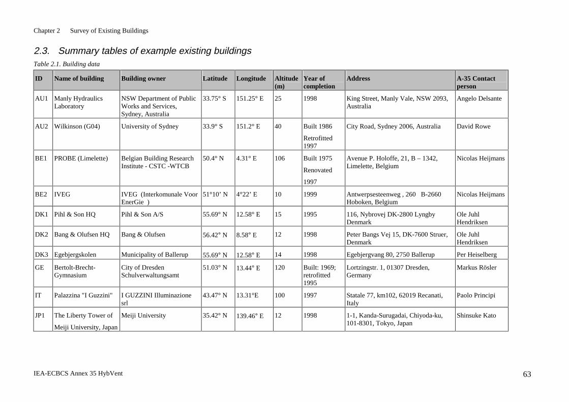
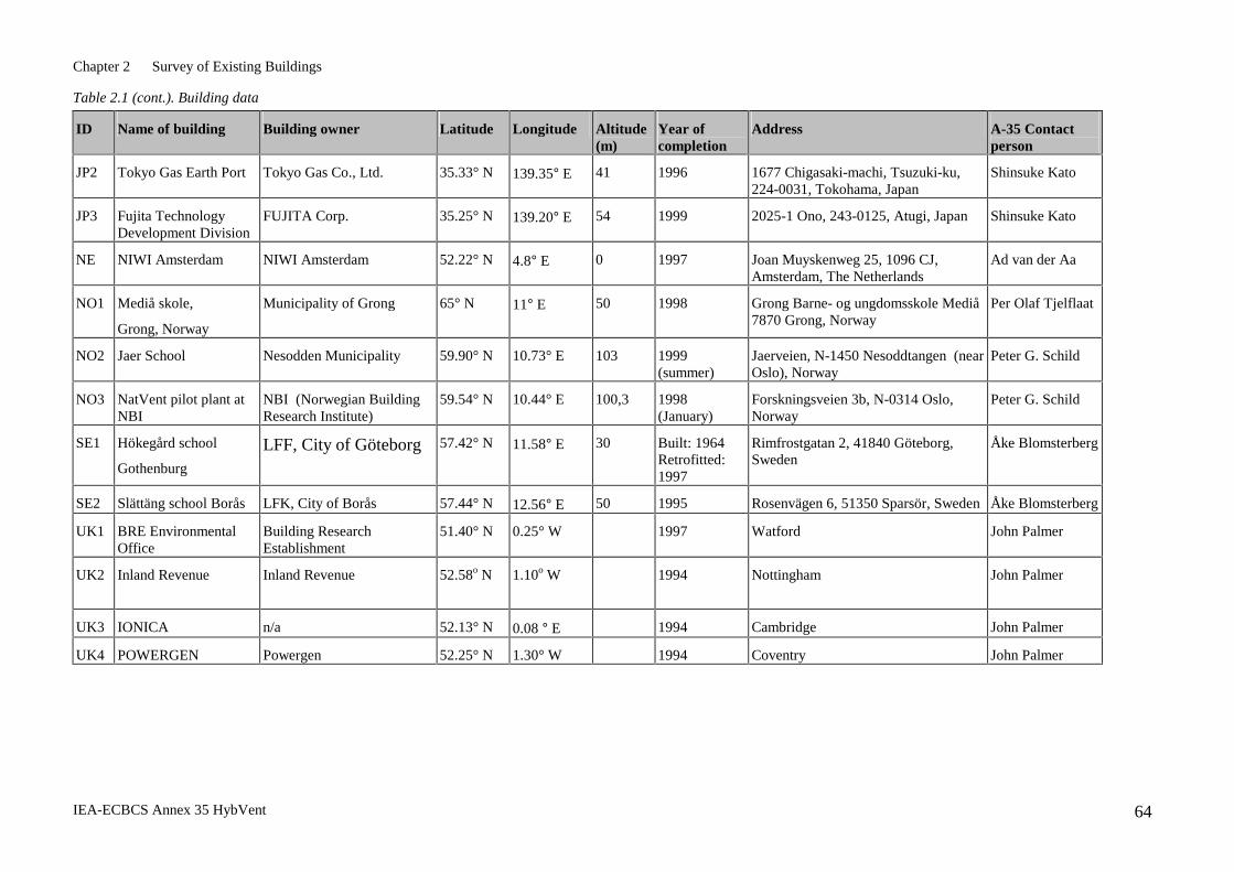
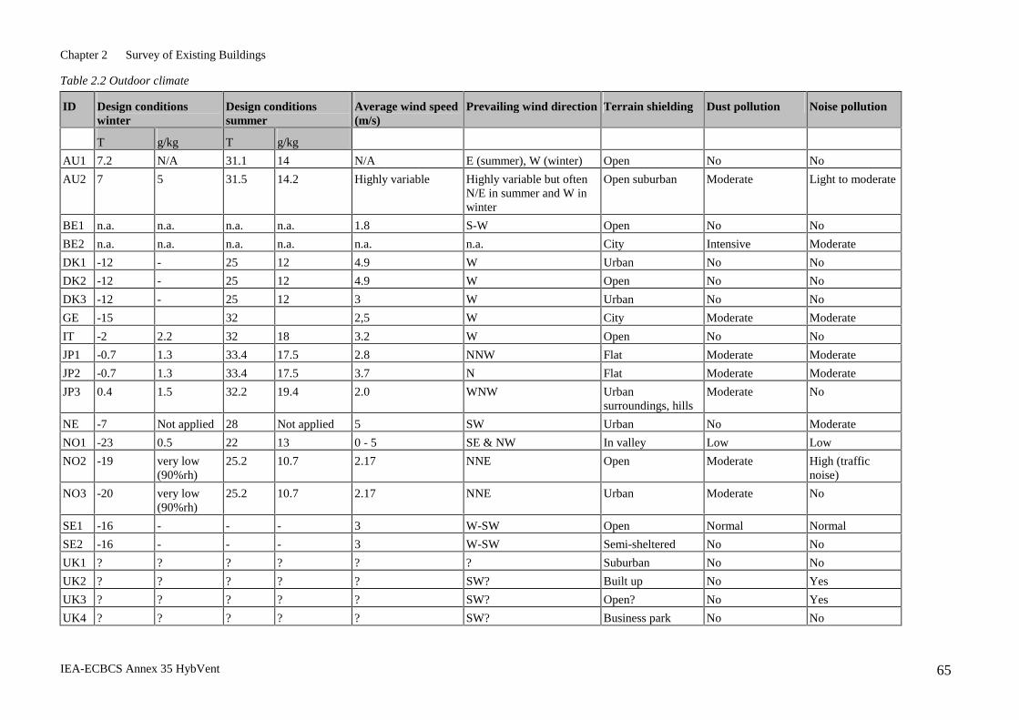
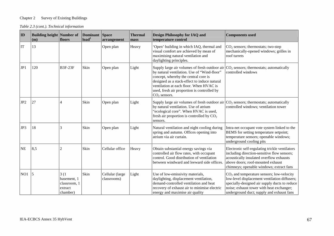
2. Survey of Existing Buildings .................................................................. 16 2.1 Overview..........................................................................................................16 2.2 Two-page descriptions of existing buildings ...................................................19 2.3 Summary tables of example existing buildings ..............................................63
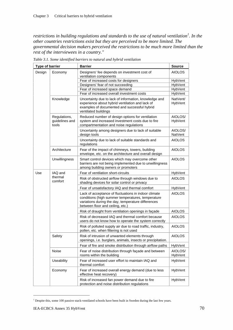
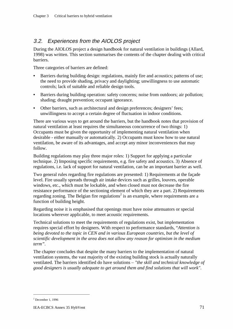
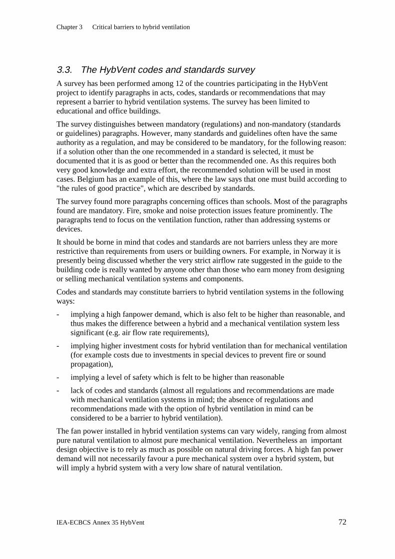
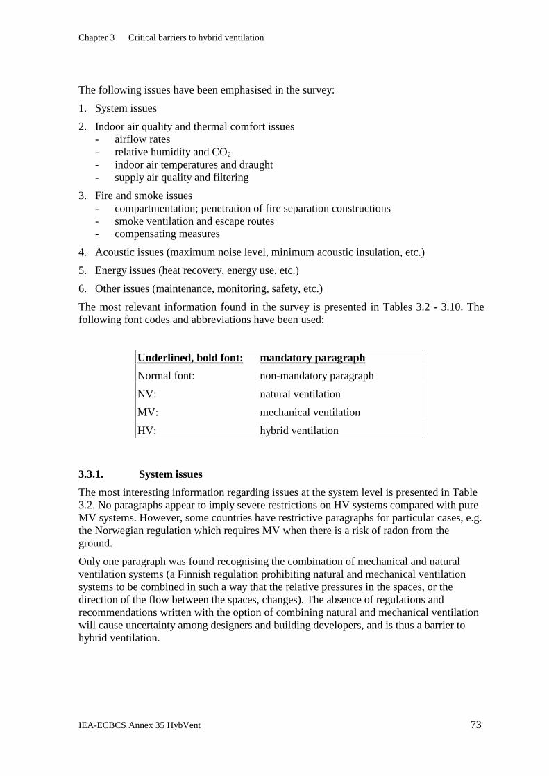
3. Critical Barriers to Hybrid Ventilation .................................................. 69 3.1 Experiences from the NatVentTM project........................................................69 3.2 Experiences from the AIOLOS project ..........................................................71 3.3 The HybVent codes and standards survey......................................................72 3.4 Other barriers ..................................................................................................90 3.5 Conclusions.....................................................................................................91 3.6 References.......................................................................................................92
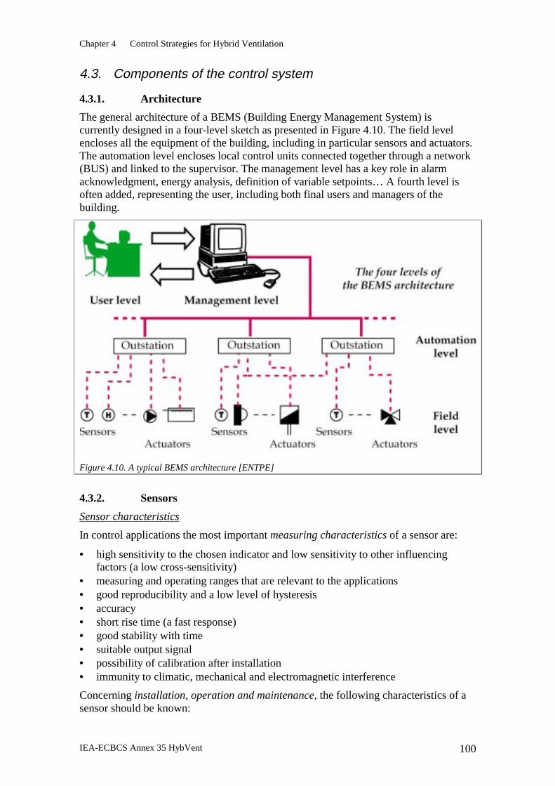
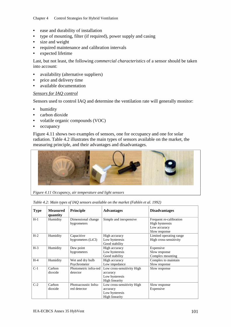
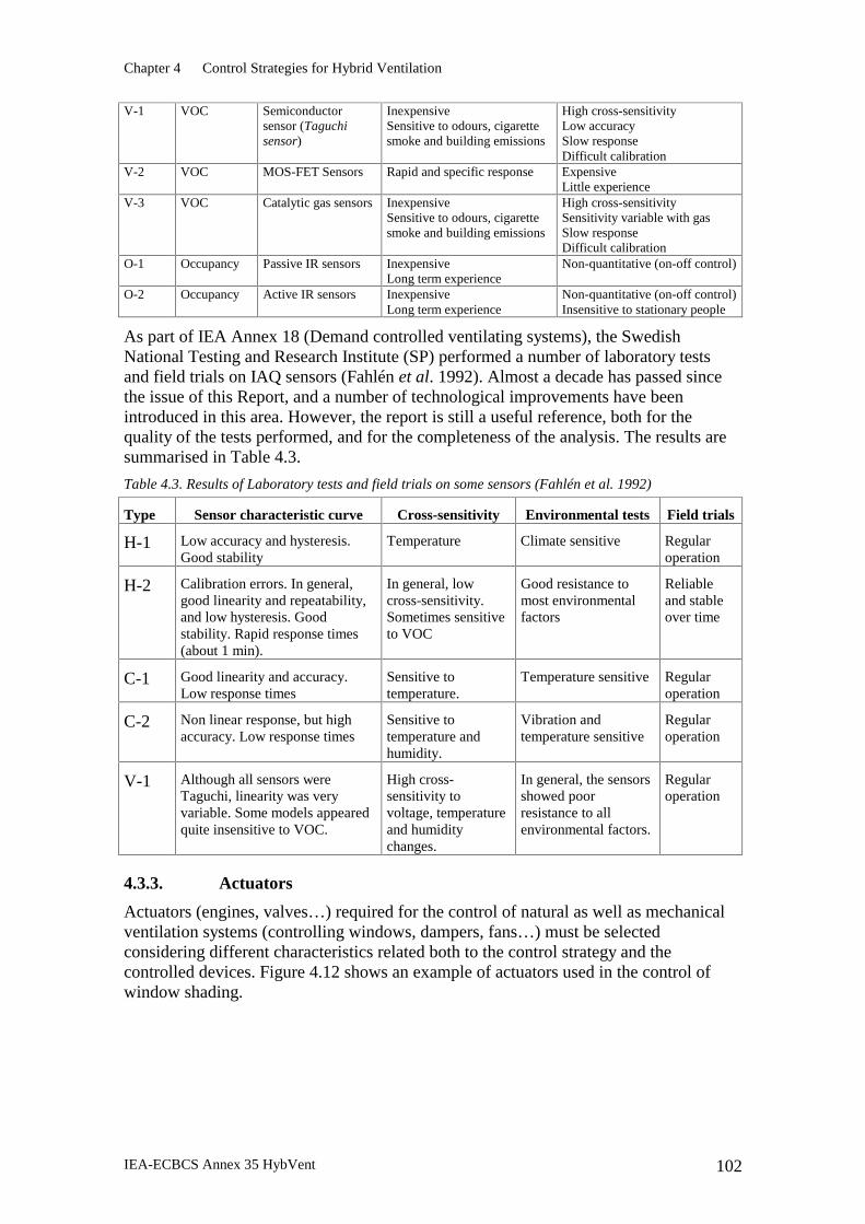
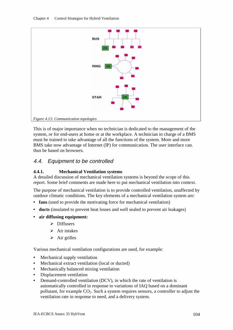
4. Control Strategies for Hybrid Ventilation ............................................. 93 4.1 Introduction.....................................................................................................93 4.2 Principles of control........................................................................................94 4.3 Components of the control system................................................................100 4.4 Equipment to be controlled...........................................................................104 4.5 Control of hybrid ventilation systems...........................................................105 4.6 Conclusions...................................................................................................106 4.7 Bibliography .................................................................................................106
5. Analysis Tools for Hybrid Ventilation ................................................. 109 5.1 Introduction...................................................................................................109 5.2 Description of available methods .................................................................110 5.3 Significant issues in analysis tools................................................................116 5.4 Conclusions...................................................................................................120 5.5 References.....................................................................................................120
EXECUTIVE SUMMARY There is a growing level of dissatisfaction with the quality of the indoor environment and the high energy consumption (and hence greenhouse gas emissions) of buildings. The indoor environment in many buildings is increasingly being seen as unsatisfactory because of poor air quality and temperature control (e.g. sick building syndrome) and, importantly, lack of local control by the occupants. Such buildings are seen as being unresponsive to the local climate. One response to these problems has been to use natural ventilation alone. However, this is often unable to provide the required indoor air quality and thermal performance. The debate between the merits of mechanical ventilation and natural ventilation has led to a polarisation of views, hindering the development of better solutions.
Hybrid ventilation (HV) offers a way forward by combining the best aspects of natural and mechanical ventilation, as appropriate at different times of the day or season of the year, to provide good air quality and a comfortable indoor environment. Because HV is based on a different design philosophy, expectations about its performance cannot be the same as for mechanical ventilation. Nevertheless, it should not be seen as lowering standards. Nor should it necessarily increase costs, but because of the different design approach, and hence the different balance between capital, running, maintenance and disposal costs, cost comparisons between hybrid and mechanical ventilation systems should be done on a life-cycle cost basis rather than simply on an initial capital cost basis.
Hybrid ventilation provides opportunities for innovative solutions to the problems of mechanically or naturally ventilated buildings. In colder countries hybrid ventilation can avoid the trend to mechanical air conditioning, which has occurred in response to higher occupant expectations, the requirements of codes and standards, and in some cases higher internal gains and changes in building design. In warmer countries it can reduce the traditional reliance on full air conditioning.
This report describes the state of the art in hybrid ventilation. Each chapter covers a particular topic as follows:
• Survey of existing buildings with hybrid ventilation systems
• Barriers to, or opportunities for, hybrid ventilation in building codes and standards
• Control strategies
• Analysis tools.
Chapter 1 Introduction Expectations of Hybrid Ventilation in the Participating Countries
The 15 countries participating in Hybvent are doing so because experts in each country believe that HV offers significant opportunities for improving the indoor environment and reducing energy demand. Naturally, because of climate variations and other factors, different countries have differing expectations of HV. Each participating country prepared a short description of their expectations of HV. Commonly-cited statements were that HV systems are expected to:
Executive Summary
IEA-ECBCS Annex 35 HybVent 5
½ Offer a wider range of design options
½ Reduce noise from fans
½ Reduce electricity demand
½ Reduce energy demand
½ Reduce CO2 emissions
½ Allow more individual control, operable windows, etc.
½ Deliver satisfactory or even improved IAQ.
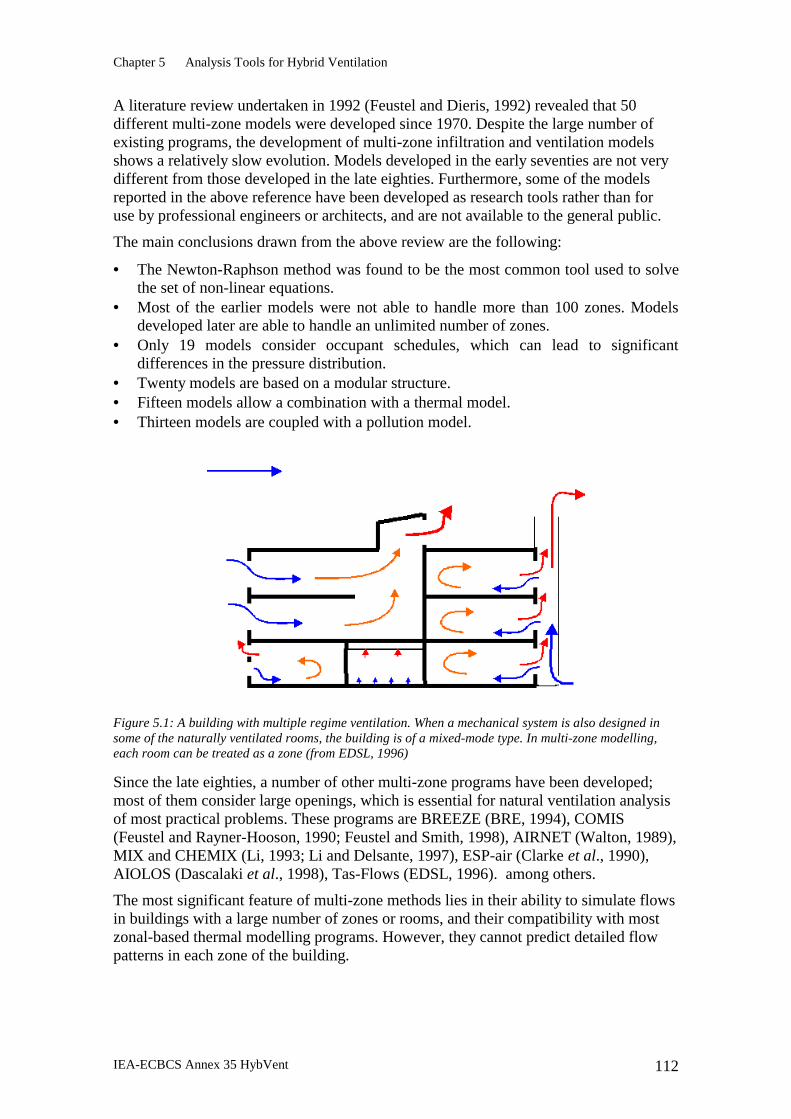
Chapter 2 Survey of Existing Buildings Quite a number of hybrid-ventilated buildings have already been built around the world, and more are planned or about to be built. Chapter 2 surveys 22 existing buildings from ten of the countries participating in this Annex. Particular topics of interest in this survey were the overall design philosophy used to ensure good IAQ and thermal comfort, the control strategies used, and the components used.
It is clear from the descriptions of the overall design philosophy that a successful hybrid ventilation design depends on an integrated approach, in which optimal use is made of sustainable technologies such as passive solar gains, daylighting and natural ventilation. In particular it requires good thermal design, and in a number of buildings thermal mass combined with intensive night ventilation (using natural forces or fan assistance) is exploited to stabilise temperatures during the day.
The buildings surveyed are low to medium-rise buildings (except for the Meiji University Tower in Tokyo), located in areas with little or moderate dust and noise pollution. Further examples of high-rise hybrid-ventilated buildings, or buildings in more challenging environments, will be useful to demonstrate that innovative solutions can be found for a wide variety of applications and environments.
Control strategies in the buildings surveyed are usually based on temperature control, with some (particularly schools) also using CO2 control. Both manual and automatic control of openings and fans is often available. More information is needed on how well the control strategies work in practice, whether there are any reliability problems with motorised openings, and similar issues.
Some basic components were used by most buildings. These include fans, CO2 and temperature sensors, manually operated and/or motorised windows or special ventilation openings, and wind towers, solar chimneys or atria for exhaust. Six buildings used underground ducts, culverts or plenums to pre-condition the supply air.
Some of the buildings surveyed have been successfully retrofitted with hybrid systems. Many existing office buildings either overheat in summer or use excessive amounts of energy to maintain acceptable temperatures, because of increasing internal heat gains from office equipment, low-efficiency lighting systems, high staff densities, and excessive solar gains. When refurbishment is due in these problem buildings, new air conditioning systems are installed to either replace a natural ventilation system or an existing air conditioning system. Thus retrofitting hybrid ventilation systems in existing buildings when they are due for refurbishment has the potential to greatly increase the impact of this technology on energy consumption and worker satisfaction and productivity.
Executive Summary
IEA-ECBCS Annex 35 HybVent 6
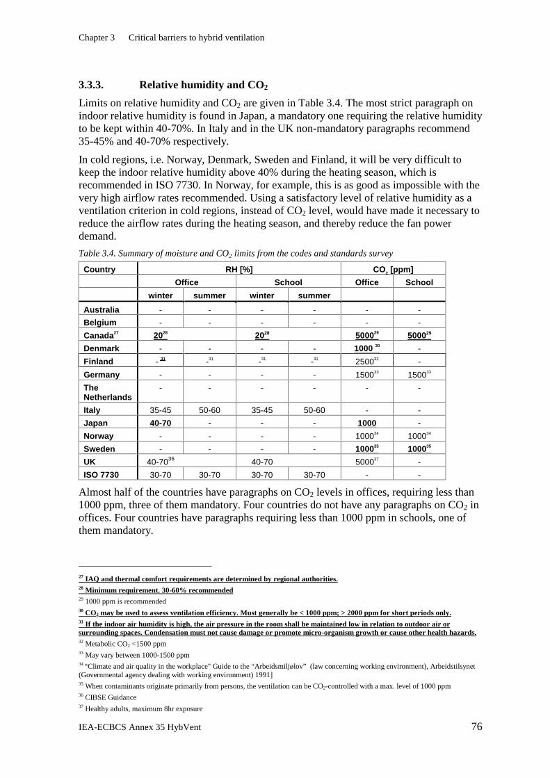
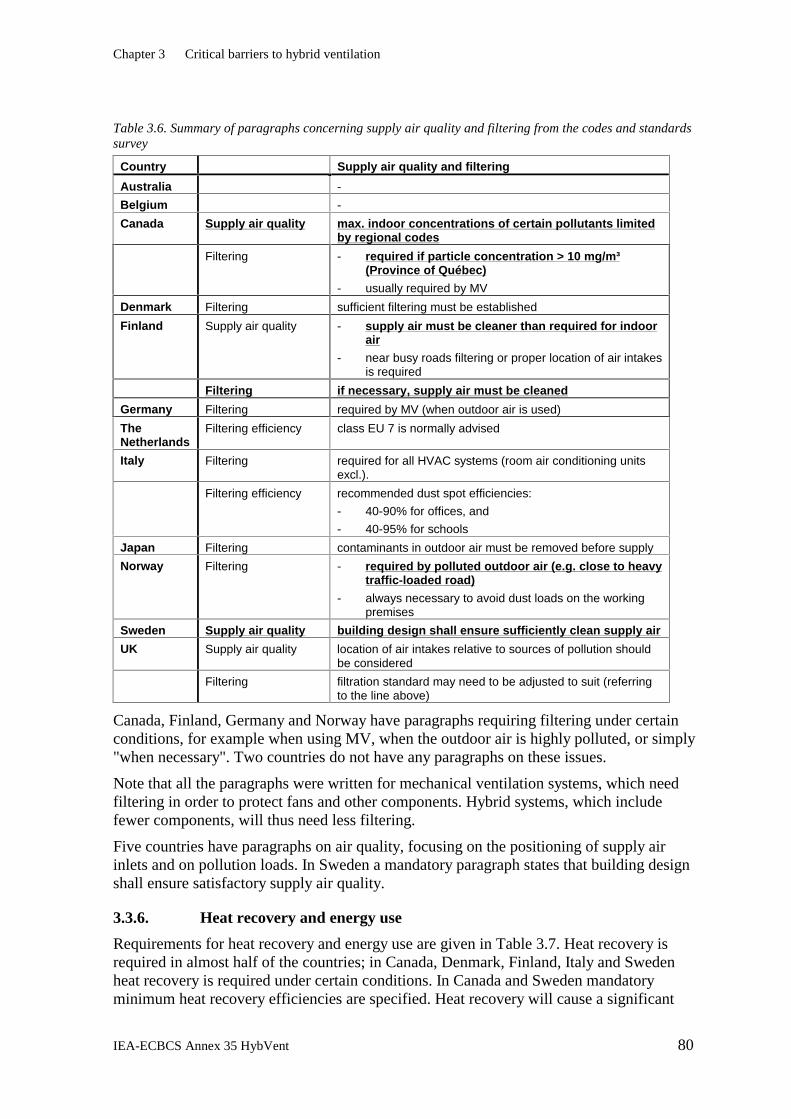
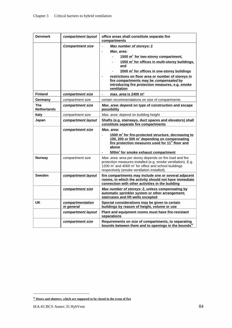
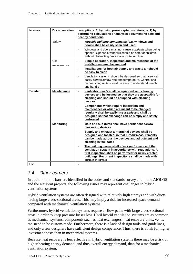
Chapter 3 Critical Barriers to Hybrid Ventilation Hybrid ventilated buildings must comply with existing building codes and standards, where they are mandatory. Chapter 3 surveys twelve of the countries participating in Annex 35 and describes the paragraphs in acts, codes, standards or recommendations that may have an impact, positive or negative, on hybrid ventilation systems. Key issues relate to indoor air quality and thermal comfort, energy performance, acoustics, and fire and safety.
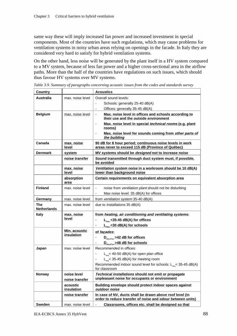
In general, none of the countries surveyed have regulations that severely restrict the general use of natural or hybrid ventilation. Some paragraphs recommend or require mechanical ventilation in special cases, for example in polluted urban areas and when radon is present in the ground. Some countries have high requirements for air flow rates, which will imply a high demand for fan power. Hybrid ventilation systems rely as much as possible on natural driving forces, although in practice they may have more or less fan power installed than mechanical systems. Thus while a requirement for high air flow rates will not necessarily favour a pure mechanical system over a hybrid system, it is not in line with the HV approach.
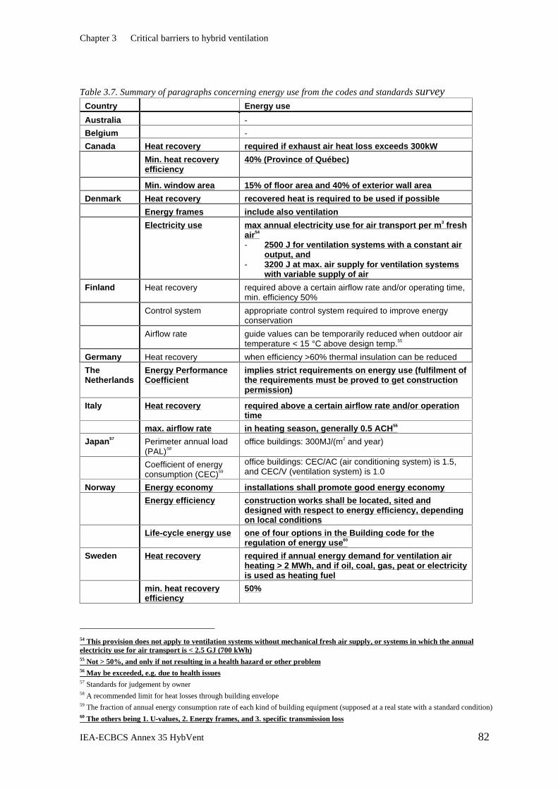
Three countries recommend a CO2-level less than 1000 ppm, which may require extensive use of fans. In areas with low pollution loads this may imply a higher fan power demand than necessary. In the five countries where heat recovery is required, this may imply an unnecessary high fan power demand, for example when using an underground supply air duct.
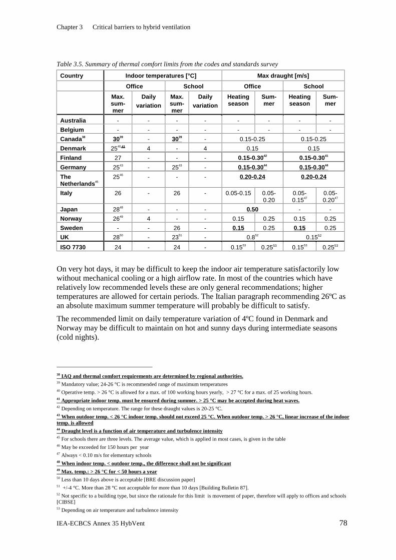
There are requirements on minimum temperatures and summer maximum temperatures, but these are mostly non-mandatory. Most countries have requirements on maximum noise levels in indoor spaces and noise generated by plant or duct systems. In addition Italy, Norway and Sweden have requirements on the acoustic insulation of façades, which may be of concern for hybrid systems since they may require façade openings.
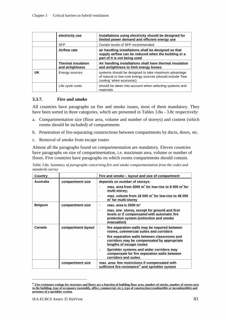
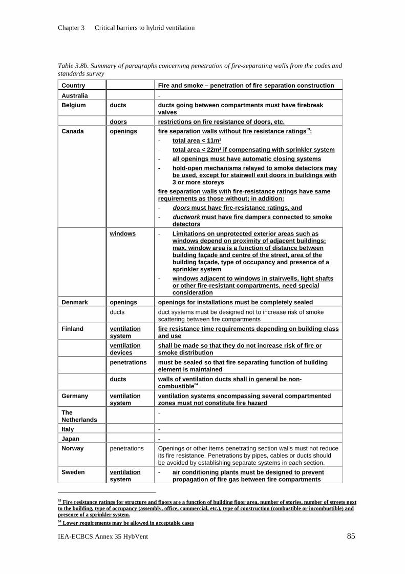
Fire, smoke and noise regulations probably represent the most serious barriers to hybrid ventilation. Paragraphs on these issues, most of them mandatory, were found in all the countries. The more open nature of buildings with hybrid ventilation systems tends to enhance the spread of smoke and fire. Hybrid ventilation systems therefore will need careful design to meet requirements on openings, compartmentation and smoke removal. However, it should be emphasised that it is often possible to satisfy fire regulations if compensatory measures such as sprinkler systems are used.
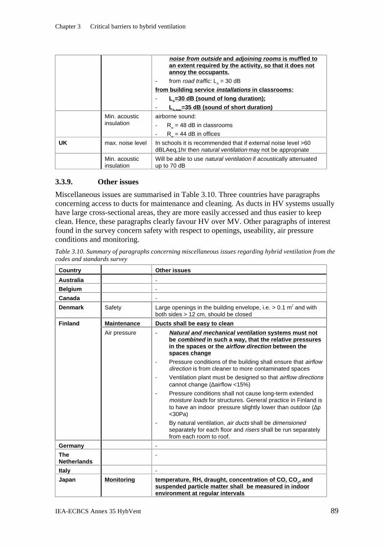
Not all the requirements in codes and standards represent a barrier. Requirements that deal with restricting electricity use, noise generated by installations and access to ducts for cleaning may favour hybrid ventilation over mechanical ventilation systems.
It is likely that almost none of the paragraphs found in the survey were written with the possibility of combining natural and mechanical ventilation in mind. The absence of such regulations and recommendations will cause uncertainty among designers and building developers, and could thus be seen as a barrier to hybrid ventilation.
Notwithstanding the barriers or challenges that may exist, it is worth emphasising that none have prevented a wide variety of hybrid-ventilated buildings being built and planned.
Executive Summary
IEA-ECBCS Annex 35 HybVent 7
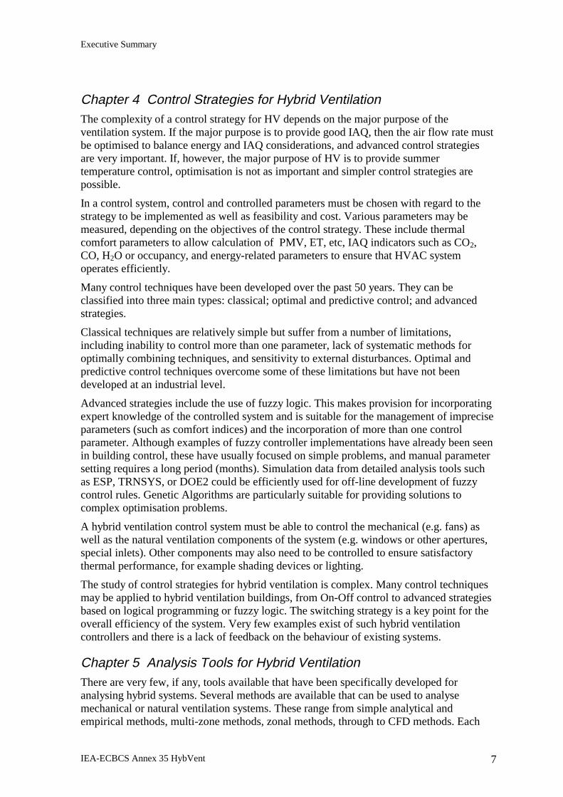
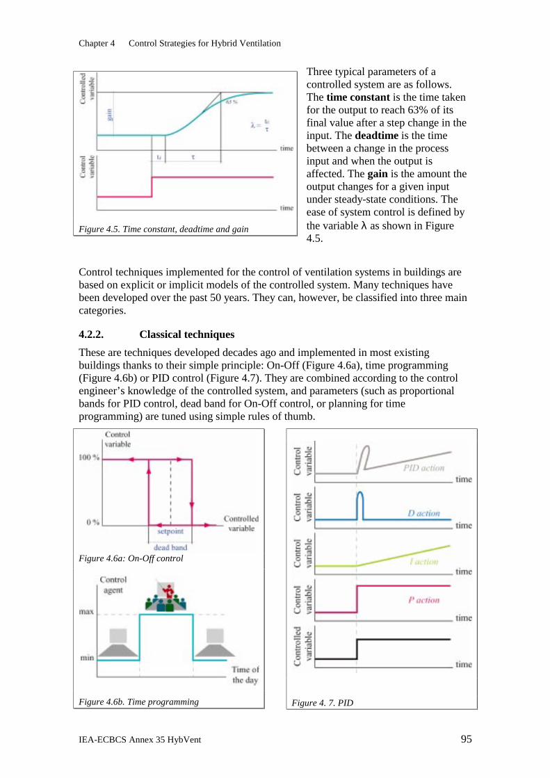
Chapter 4 Control Strategies for Hybrid Ventilation The complexity of a control strategy for HV depends on the major purpose of the ventilation system. If the major purpose is to provide good IAQ, then the air flow rate must be optimised to balance energy and IAQ considerations, and advanced control strategies are very important. If, however, the major purpose of HV is to provide summer temperature control, optimisation is not as important and simpler control strategies are possible.
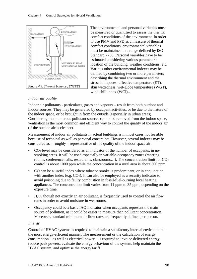
In a control system, control and controlled parameters must be chosen with regard to the strategy to be implemented as well as feasibility and cost. Various parameters may be measured, depending on the objectives of the control strategy. These include thermal comfort parameters to allow calculation of PMV, ET, etc, IAQ indicators such as CO2, CO, H2O or occupancy, and energy-related parameters to ensure that HVAC system operates efficiently.
Many control techniques have been developed over the past 50 years. They can be classified into three main types: classical; optimal and predictive control; and advanced strategies.
Classical techniques are relatively simple but suffer from a number of limitations, including inability to control more than one parameter, lack of systematic methods for optimally combining techniques, and sensitivity to external disturbances. Optimal and predictive control techniques overcome some of these limitations but have not been developed at an industrial level.
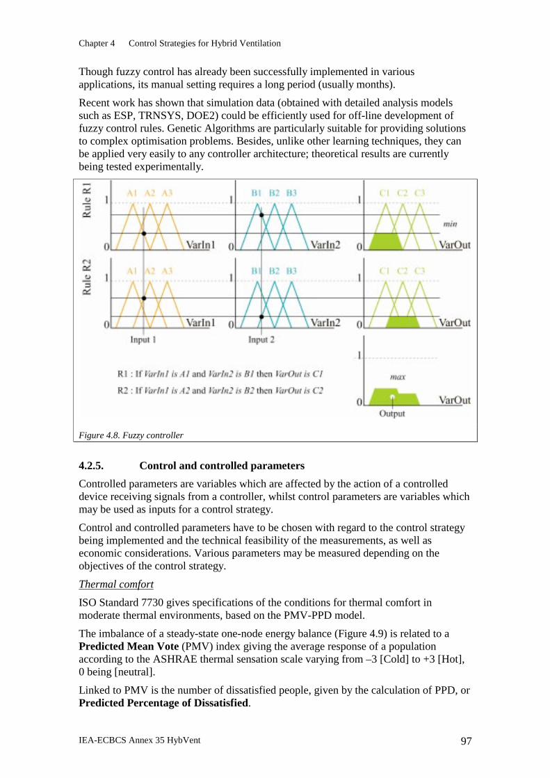
Advanced strategies include the use of fuzzy logic. This makes provision for incorporating expert knowledge of the controlled system and is suitable for the management of imprecise parameters (such as comfort indices) and the incorporation of more than one control parameter. Although examples of fuzzy controller implementations have already been seen in building control, these have usually focused on simple problems, and manual parameter setting requires a long period (months). Simulation data from detailed analysis tools such as ESP, TRNSYS, or DOE2 could be efficiently used for off-line development of fuzzy control rules. Genetic Algorithms are particularly suitable for providing solutions to complex optimisation problems.
A hybrid ventilation control system must be able to control the mechanical (e.g. fans) as well as the natural ventilation components of the system (e.g. windows or other apertures, special inlets). Other components may also need to be controlled to ensure satisfactory thermal performance, for example shading devices or lighting.
The study of control strategies for hybrid ventilation is complex. Many control techniques may be applied to hybrid ventilation buildings, from On-Off control to advanced strategies based on logical programming or fuzzy logic. The switching strategy is a key point for the overall efficiency of the system. Very few examples exist of such hybrid ventilation controllers and there is a lack of feedback on the behaviour of existing systems.
Chapter 5 Analysis Tools for Hybrid Ventilation There are very few, if any, tools available that have been specifically developed for analysing hybrid systems. Several methods are available that can be used to analyse mechanical or natural ventilation systems. These range from simple analytical and empirical methods, multi-zone methods, zonal methods, through to CFD methods. Each
Executive Summary
IEA-ECBCS Annex 35 HybVent 8
has their own area of applicability, e.g. conceptual design, preliminary design, detailed design, or system performance evaluation. Multi-zone methods probably offer the best prospect of a balance between computational efficiency and accuracy.
In fact, the existing building survey revealed that only a few buildings used any kind of design tool, much less one designed for hybrid ventilation systems.
Because hybrid systems combine natural and mechanical ventilation, they present several complex challenges to analysis tools, requiring a global approach that takes into account the outdoor environment, the indoor environment, and the mechanical system. For example, control systems developed for hybrid systems will switch between a natural ventilation mode, which may result in stratified temperatures in the space, to a mechanical mode with mixed air and no stratification. The analysis tool must be able to deal with these mode switches, and it must also be able to model the (possibly complex) control strategy itself. Furthermore, because hybrid ventilation systems are often used for temperature control as well as for IAQ control, analysis tools must be able to integrate thermal modelling with ventilation modelling. Some integrated tools of this type are already available, but further work is needed to model the mutual interaction of thermal stratification and natural and mechanical air flow rates. There are also several outstanding problems in modelling natural ventilation that will need to be addressed:
• Developing reliable methods for estimating wind pressure coefficients for complex buildings
• Understanding wind-driven flows through large openings, in particular the validity of using wind-pressure coefficients obtained for solid surfaces
• Developing better data, e.g. discharge coefficients and component flow characteristics. As new specifically-designed components become available, their performance characteristics will need to be known.
Finally, to increase confidence in the use of hybrid ventilation analysis tools and methods, it will be necessary to develop benchmark problems and solutions to enable the evaluation of these analysis tools.
Chapter 1 Introduction
IEA-ECBCS Annex 35 HybVent 9
1. INTRODUCTION The primary purpose of ventilation is to provide acceptable indoor air quality and indoor temperatures. Hybrid ventilation takes advantage of natural ventilation forces, using mechanical forces only when natural forces do not suffice. In natural ventilation the forces of wind and air density differences are used to move air through the building. Natural ventilation is the oldest form of ventilation strategy, and in recent years has been revitalised as a response to a number of challenges in the built environment.
Immediately after the energy crisis in 1973 attention was focused on thermal insulation, airtightness of buildings and heat recovery to decrease the heating and cooling energy consumption of buildings. Buildings were designed to be isolated from the outdoor environment, with an indoor environment controlled by artificial lighting and mechanical ventilation, heating and cooling systems.
Today, in the design of new buildings and retrofit of old buildings, attention has turned towards a more integrated design with a focus not only on thermal insulation, airtightness and heat recovery but also on optimal use of sustainable technologies such as passive solar gains, daylighting and natural ventilation and cooling. Buildings are designed to interact with the outdoor environment and they utilize the outdoor environment to create an acceptable indoor environment whenever doing so is beneficial.
The extent to which sustainable technologies can be utilized depends on outdoor climate, building use, building location and design. Under optimum conditions sustainable technologies will be able to satisfy the demands for heat, light and fresh air. In some cases supplementary mechanical systems will be needed and in other cases it will not be possible to use sustainable technologies at all.
In well-insulated office buildings, which are becoming more and more common in IEA countries, ventilation and cooling account for more than 50% of the energy requirement; hence a well-controlled and energy-efficient ventilation system is a prerequisite of low energy consumption. Natural ventilation and passive cooling are sustainable, energy-efficient and clean technologies as long as they can be adequately controlled.
Unfortunately, the design of energy-efficient ventilation systems in office buildings has often become a question of using either natural ventilation and passive cooling or mechanical ventilation and cooling. This polarisation hinders the widespread use of sustainable technologies. In fact in the majority of cases a combination of technologies would be beneficial, depending on outdoor climate, building design, building use and the main purpose of the ventilation system.
The number of office buildings to be retrofitted in most IEA countries is now much larger than the potential for new buildings. In many cases there is a large potential for use of sustainable technologies either as a supplement to existing mechanical systems or as a replacement for conventional systems. Therefore, there is certainly a need for the development of innovative hybrid ventilation systems.
Suitable validated design tools as we know them for mechanical systems are not available for hybrid ventilation systems. Such tools would give architects and engineers the necessary confidence in system performance, which in many cases is the decisive factor in the choice of system design.
Chapter 1 Introduction
IEA-ECBCS Annex 35 HybVent 10
Thorough control of hybrid ventilation in new as well as in retrofitted buildings requires a completely integrated approach, i.e. one involving building design, its technical systems, occupant behaviour, topography of surroundings, climatic and meteorological conditions.
1.1 Mechanical ventilation The conventional way to ventilate non-residential buildings today is to supply fresh air from the exterior and to extract polluted air with a balanced mechanical ventilation system, consisting of fans and ductwork. The system normally also comprises filters, dampers, silencers, heat exchangers, etc. Such systems are able to deliver a stable supply of fresh air, which ensures an air quality and thermal comfort that is independent of outside conditions.
However, today’s ventilation systems are quite complex and expensive to install and operate. A common trend towards higher indoor air quality standards has resulted in ventilation systems that require an increasingly larger share of the building costs. Mechanical ventilation systems also consume considerable amounts of electricity for fans. The complexity of such ventilation systems provides many opportunities for malfunctions.
The air quality in conventionally ventilated buildings has been questioned lately, with an increased occurrence of sick building syndrome and other air quality-related health problems. Many explanations have been proposed for these problems: under-designed fresh air supply, badly engineered systems, malfunctioning components, improper adjustments, neglected maintenance, poor construction, etc. Due to bad design, assembly and operation, dust and contaminants are often accumulated in ductwork, filters etc. Thus it is necessary to clean all internal surfaces of the systems at regular intervals. As most of the ductwork has relatively small dimensions, this is both a time- and cost-consuming operation, which very rarely is performed at prescribed intervals. Dust and contaminants may also cause poor performance in the ventilation plant. Therefore, filters are installed to prevent such problems. The filters increase the pressure drop in the system, so that even more fan power is needed.
1.2 Hybrid ventilation - the revitalisation of old principles As occupant requirements for indoor air comfort increase, mechanical ventilation systems will necessarily become more and more expensive and demanding with respect to maintenance, energy consumption, and space demands. Recently, as this trend has become more evident, the "forgotten" principle of natural ventilation has been discussed and also tested in several countries.
Traditional natural ventilation systems offer very little control of the airflow, and do not provide the level of comfort occupants expect from modern buildings. They also require large amounts of energy to heat the fresh air to comfort temperatures in winter, as heat recovery systems are not provided.
Advances in computer technology over recent years have made natural ventilation more relevant than ever before due to two important factors (Vik 1998):
• the increased power of computer hardware and the development of numerical calculation software now makes it possible to calculate and predict the performance of a natural ventilation system for different outdoor climate conditions and ventilation demand situations;
Chapter 1 Introduction
IEA-ECBCS Annex 35 HybVent 11
• the different components of a natural ventilation system can be monitored, controlled and co-ordinated by smart computer programs, which can also enable occupants to control the indoor climate individually.
Hybrid ventilation systems that combine natural and mechanical driving forces have been applied to modern buildings during the last few years. This has made it possible to satisfy relatively strict indoor air quality requirements for most of the time.
The focus on the environmental impacts of electricity production and consumption has provided an increased awareness of the energy used by fans and other equipment in an air conditioning system. Even with some assisting fans installed, a hybrid ventilation system will probably use less electricity than an ordinary mechanical ventilation system.
Such ventilation principles will result in buildings with very little visible conventional ventilation equipment, as the building itself provides the ductwork. The investments in mechanical equipment will be shifted towards a larger investment in the building itself: increased room air volume per person, a shape favourable for air movement, a more complex facade/window system, underground intake air culverts, extract air "smoke" stacks, etc. Thus, modern natural and hybrid ventilation systems will have a large impact on the building design, making close cooperation between the architect, the civil engineer and the HVAC engineer a necessity.
Of course hybrid ventilation systems have their own limitations. Depending on the amount of fan power installed, a hybrid system may not be able to keep the indoor temperature low enough on hot days. Another drawback is that the integration of filtering units will increase the need for fan power significantly. In addition, the use of heat recovery systems will decrease the buoyancy forces and thus increase the need for fan power, and heat recovery efficiency is poorer than in pure mechanical ventilation systems. Finally, the risk for noise transfer through airflow paths has to be given special attention in the design of a hybrid ventilation system.
Some citations from literature regarding natural and hybrid ventilation:
- Buoyancy and wind, used correctly, can help us naturally ventilate even the tallest and lowest buildings. Natural ventilation does not limit the scope of architectural design; instead, it may lead to interesting new solutions, possibly even to a new architectural language (Daniels 1995).
- After a visit in a school building in Sweden with a hybrid ventilation system, it was reported (Tjelflaat and Rødahl 1997) that one of the most important impressions was the absence of noise from the ventilation system and the "feeling" of fresh air.
- Furthermore, natural ventilation seems to provide an answer to many complaints from users concerning mechanical ventilation, which appears to be noisy, to create health problems (sick building syndrome is usually associated with mechanical HVAC systems), to require routine maintenance and to consume energy. In contrast, natural ventilation is preferred by the occupants, since it is energy efficient (no need for a mechanical system), it can be easily integrated into buildings and it provides a healthier and more comfortable environment if integrated correctly (Allard 1998).
1.3 Expectations of hybrid ventilation from Annex 35 participants The 15 countries participating in Hybvent are doing so because experts in each country believe that HV offers significant opportunities for improving the indoor environment and reducing energy demand. Naturally, because of climate variations and other factors,
Chapter 1 Introduction
IEA-ECBCS Annex 35 HybVent 12
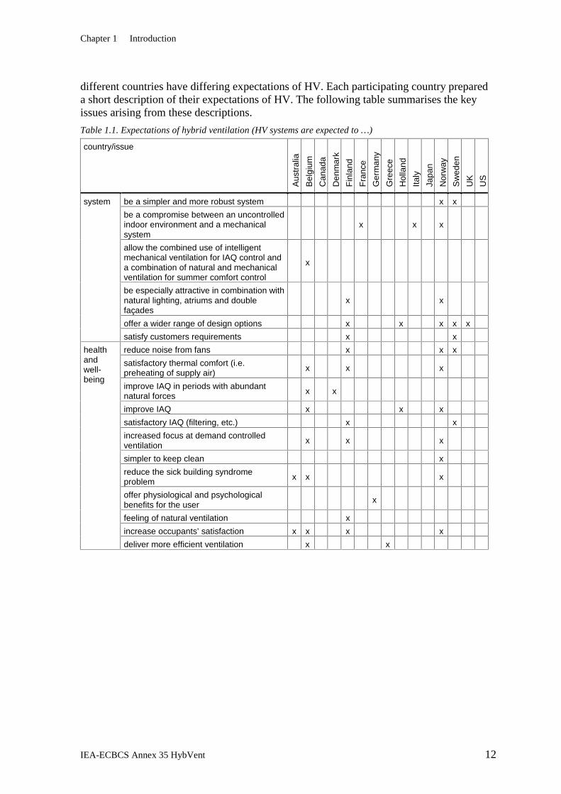
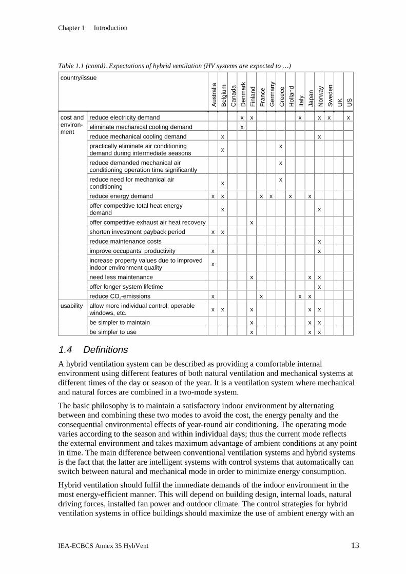
different countries have differing expectations of HV. Each participating country prepared a short description of their expectations of HV. The following table summarises the key issues arising from these descriptions.
Table 1.1. Expectations of hybrid ventilation (HV systems are expected to …)
country/issue
Aus
tral
ia
Bel
gium
Can
ada
Den
mar
k
Fin
land
Fra
nce
Ger
man
y
Gre
ece
Hol
land
Italy
Japa
n
Nor
way
Sw
eden
UK
US
be a simpler and more robust system x x
be a compromise between an uncontrolled indoor environment and a mechanical system
x
x x
allow the combined use of intelligent mechanical ventilation for IAQ control and a combination of natural and mechanical ventilation for summer comfort control
x
be especially attractive in combination with natural lighting, atriums and double façades
x
x
offer a wider range of design options x x x x x
system
satisfy customers requirements x x
reduce noise from fans x x x
satisfactory thermal comfort (i.e. preheating of supply air) x x
x
improve IAQ in periods with abundant natural forces x x
improve IAQ x x x
satisfactory IAQ (filtering, etc.) x x
increased focus at demand controlled ventilation
x x
x
simpler to keep clean x
reduce the sick building syndrome problem x x
x
offer physiological and psychological benefits for the user
x
feeling of natural ventilation x
increase occupants’ satisfaction x x x x
health and well-being
deliver more efficient ventilation x x
Chapter 1 Introduction
IEA-ECBCS Annex 35 HybVent 13
Table 1.1 (contd). Expectations of hybrid ventilation (HV systems are expected to …)
country/issue
Aus
tral
ia
Bel
gium
Can
ada
Den
mar
k
Fin
land
Fra
nce
Ger
man
y
Gre
ece
Hol
land
Italy
Japa
n
Nor
way
Sw
eden
UK
US
reduce electricity demand x x x x x x
eliminate mechanical cooling demand x
reduce mechanical cooling demand x x
practically eliminate air conditioning demand during intermediate seasons x
x
reduce demanded mechanical air conditioning operation time significantly
x
reduce need for mechanical air conditioning x
x
reduce energy demand x x x x x x
offer competitive total heat energy demand x
x
offer competitive exhaust air heat recovery x
shorten investment payback period x x
reduce maintenance costs x
improve occupants’ productivity x x
increase property values due to improved indoor environment quality
x
need less maintenance x x x
offer longer system lifetime x
cost and environ-ment
reduce CO2-emissions x x x x
allow more individual control, operable windows, etc. x x x
x x
be simpler to maintain x x x
usability
be simpler to use x x x
1.4 Definitions A hybrid ventilation system can be described as providing a comfortable internal environment using different features of both natural ventilation and mechanical systems at different times of the day or season of the year. It is a ventilation system where mechanical and natural forces are combined in a two-mode system.
The basic philosophy is to maintain a satisfactory indoor environment by alternating between and combining these two modes to avoid the cost, the energy penalty and the consequential environmental effects of year-round air conditioning. The operating mode varies according to the season and within individual days; thus the current mode reflects the external environment and takes maximum advantage of ambient conditions at any point in time. The main difference between conventional ventilation systems and hybrid systems is the fact that the latter are intelligent systems with control systems that automatically can switch between natural and mechanical mode in order to minimize energy consumption.
Hybrid ventilation should fulfil the immediate demands of the indoor environment in the most energy-efficient manner. This will depend on building design, internal loads, natural driving forces, installed fan power and outdoor climate. The control strategies for hybrid ventilation systems in office buildings should maximize the use of ambient energy with an
Chapter 1 Introduction
IEA-ECBCS Annex 35 HybVent 14
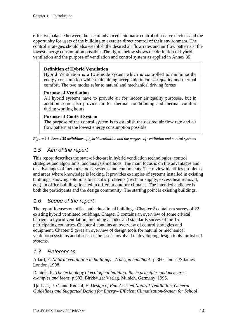
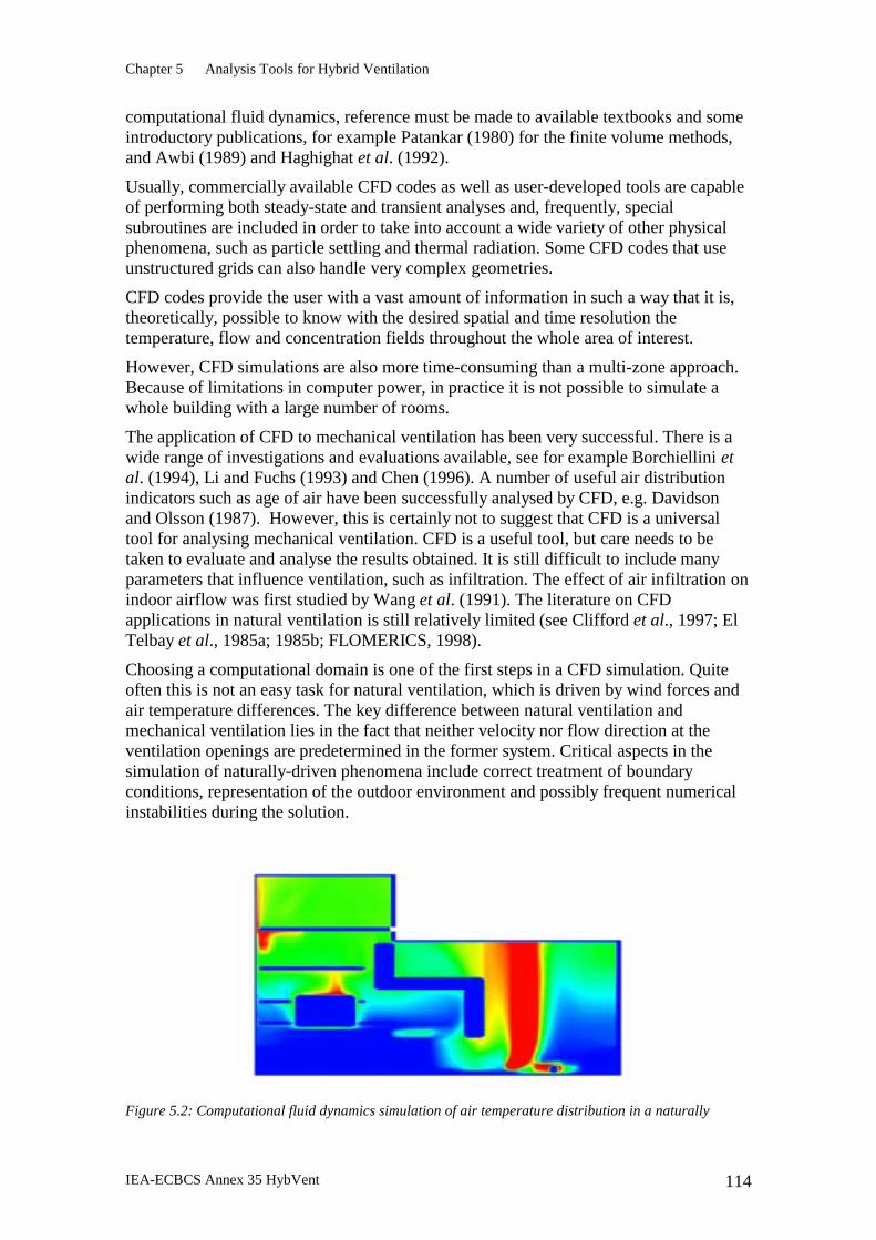
effective balance between the use of advanced automatic control of passive devices and the opportunity for users of the building to exercise direct control of their environment. The control strategies should also establish the desired air flow rates and air flow patterns at the lowest energy consumption possible. The figure below shows the definition of hybrid ventilation and the purpose of ventilation and control system as applied in Annex 35.
Figure 1.1. Annex 35 definitions of hybrid ventilation and the purpose of ventilation and control systems
1.5 Aim of the report This report describes the state-of-the-art in hybrid ventilation technologies, control strategies and algorithms, and analysis methods. The main focus is on the advantages and disadvantages of methods, tools, systems and components. The review identifies problems and areas where knowledge is lacking. It provides examples of systems installed in existing buildings, showing solutions to specific problems (fresh air supply, excess heat removal, etc.), in office buildings located in different outdoor climates. The intended audience is both the participants and the design community. The starting point is existing buildings.
1.6 Scope of the report The report focuses on office and educational buildings. Chapter 2 contains a survey of 22 existing hybrid ventilated buildings. Chapter 3 contains an overview of some critical barriers to hybrid ventilation, including a codes and standards survey of the 15 participating countries. Chapter 4 contains an overview of control strategies and equipment. Chapter 5 gives an overview of design tools for natural or mechanical ventilation systems and discusses the issues involved in developing design tools for hybrid systems.
1.7 References Allard, F. Natural ventilation in buildings - A design handbook. p 360. James & James, London, 1998.
Daniels, K. The technology of ecological building. Basic principles and measures, examples and ideas. p 302. Birkhäuser Verlag. Munich, Germany, 1995.
Tjelflaat, P. O. and Rødahl, E. Design of Fan-Assisted Natural Ventilation. General Guidelines and Suggested Design for Energy- Efficient Climatization-System for School
Definition of Hybrid Ventilation Hybrid Ventilation is a two-mode system which is controlled to minimize the energy consumption while maintaining acceptable indoor air quality and thermal comfort. The two modes refer to natural and mechanical driving forces
Purpose of Ventilation All hybrid systems have to provide air for indoor air quality purposes, but in addition some also provide air for thermal conditioning and thermal comfort during working hours
Purpose of Control System The purpose of the control system is to establish the desired air flow rate and air flow pattern at the lowest energy consumption possible
Chapter 1 Introduction
IEA-ECBCS Annex 35 HybVent 15
Building in Grong, Norway. Trondheim, SINTEF Civil and Environmental Engineering, Architecture and Building Technology, 997.
Vik, T. A. Natural and hybrid ventilation in buildings. Technology state-of-the-art 1998. Trondheim, Norway, SINTEF, 1998.
Chapter 2 Survey of Existing Buildings
IEA-ECBCS Annex 35 HybVent 16
2. SURVEY OF EXISTING BUILDINGS This chapter surveys some recent existing Hybrid Ventilation buildings, systems and components. Key information is presented via two-page reviews of example hybrid-ventilated buildings from each country participating in Sub-Task C, and via summary tables giving some basic data for each building.
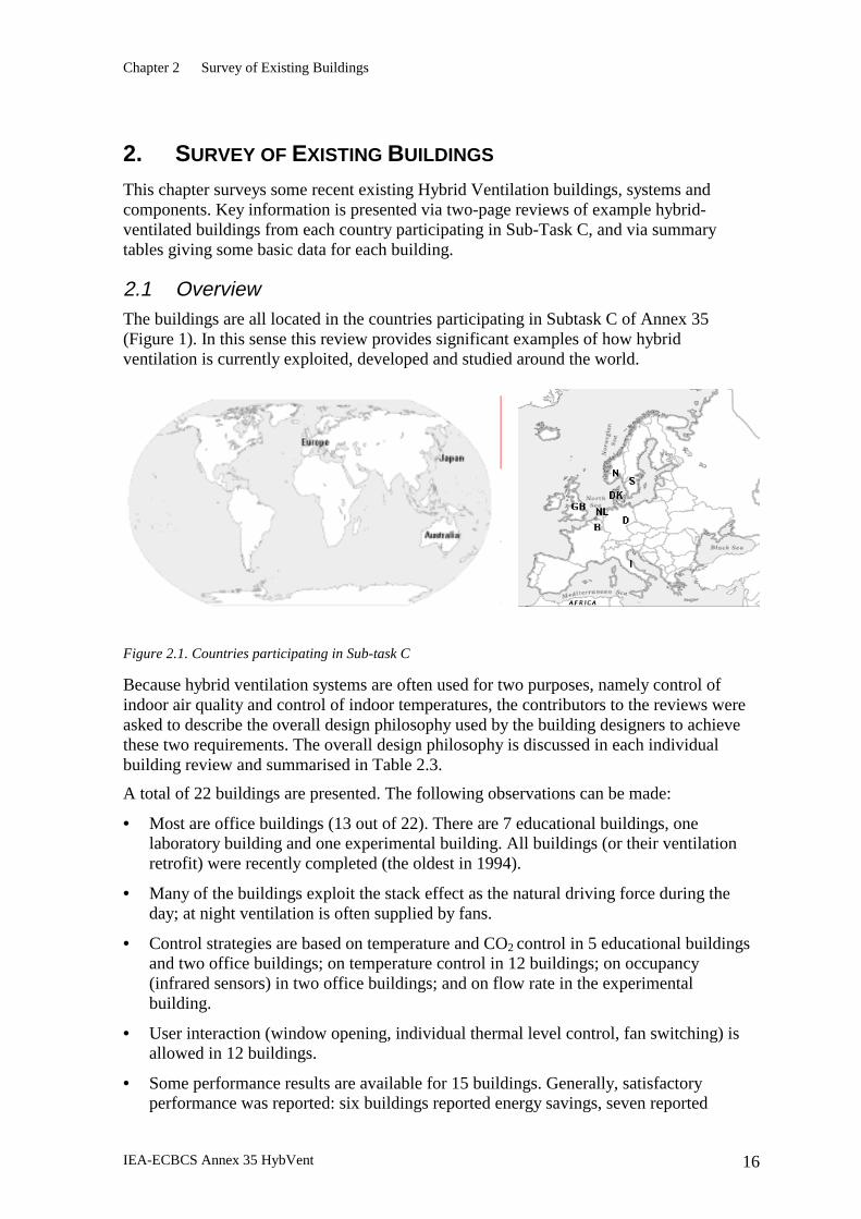
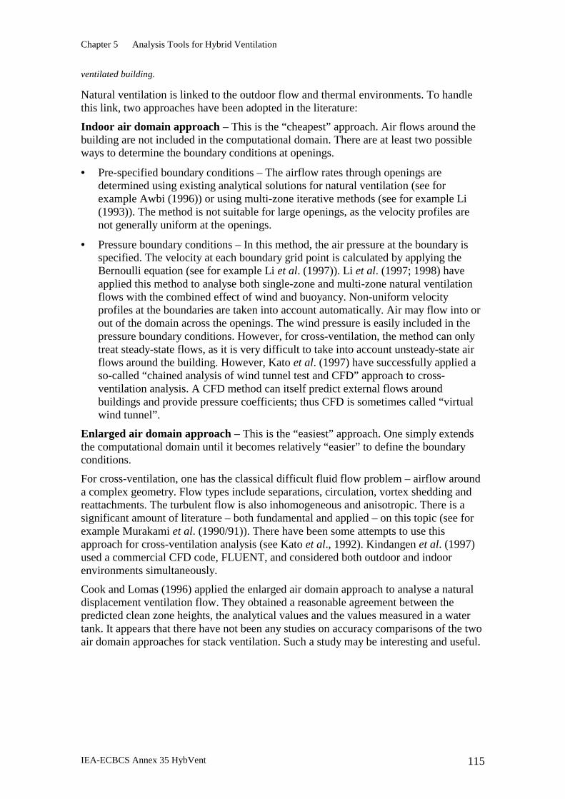
2.1 Overview The buildings are all located in the countries participating in Subtask C of Annex 35 (Figure 1). In this sense this review provides significant examples of how hybrid ventilation is currently exploited, developed and studied around the world.
Figure 2.1. Countries participating in Sub-task C
Because hybrid ventilation systems are often used for two purposes, namely control of indoor air quality and control of indoor temperatures, the contributors to the reviews were asked to describe the overall design philosophy used by the building designers to achieve these two requirements. The overall design philosophy is discussed in each individual building review and summarised in Table 2.3.
A total of 22 buildings are presented. The following observations can be made:
• Most are office buildings (13 out of 22). There are 7 educational buildings, one laboratory building and one experimental building. All buildings (or their ventilation retrofit) were recently completed (the oldest in 1994).
• Many of the buildings exploit the stack effect as the natural driving force during the day; at night ventilation is often supplied by fans.
• Control strategies are based on temperature and CO2 control in 5 educational buildings and two office buildings; on temperature control in 12 buildings; on occupancy (infrared sensors) in two office buildings; and on flow rate in the experimental building.
• User interaction (window opening, individual thermal level control, fan switching) is allowed in 12 buildings.
• Some performance results are available for 15 buildings. Generally, satisfactory performance was reported: six buildings reported energy savings, seven reported
Chapter 2 Survey of Existing Buildings
IEA-ECBCS Annex 35 HybVent 17
comfort improvements, and two reported very good IAQ. In some cases a control strategy adjustment is required, and Denmark 1 reported some noise and draught problems.
• Some of the buildings have been retrofitted (Australia 2, Belgium 1, Denmark 3, Germany, Sweden 1). This is useful as it demonstrates the possibility of introducing hybrid ventilation systems in existing buildings: in some countries retrofit will be the most important part of the future building market.
The components used to solve problems presented by the particular needs of hybrid ventilation systems are of particular interest in reviewing the state of the art. Contributors were therefore asked to describe the components used to solve or address a variety of problems and issues. The components used are summarised below.
2.1.1. IAQ control
The most common components used were local CO2 sensors and manual and/or automatically operated windows, skylights or special openings. In the Belgian buildings, an infra-red presence detection system was used to control the mechanical ventilation system.
2.1.2. Temperature control
Local temperature sensors were commonly used. A number of buildings used solar shading and high-efficiency lighting to control heat gains, and in the Belgian buildings the lighting was controlled by luminance sensors. Seven buildings used underground ducts, culverts or plenums to pre-condition the supply air.
2.1.3. Energy conservation
In most of the buildings surveyed considerable care was taken to ensure that the building was thermally efficient. The most common measures taken were good insulation levels and use of high-performance glazing. High-efficiency heating systems, and skylights, rooflights, and reflectors to provide daylighting and were also used.
2.1.4. Ensuring low pressure drops
Low pressure drops were ensured by avoiding the use of ducts (Australia 1, Denmark 3, UK 4), by using large ducts or other components to transport air (e.g. corridors) (Norway 1 and 2, Sweden 1 and 2, UK 2), by using low pressure drop dampers in extract cowls (Denmark 2), or by terminating fitout screens below the ceiling height (UK 2).
2.1.5. Control of air flow rate
Inlet and/or extract fans were often used to ensure a sufficient flow rate. In Denmark 2 frequency-controlled axial fans are controlled by air velocity sensors situated in the extracts. The Netherlands building used electronic self-regulating trickle ventilators with direction-sensitive flow sensors. Many buildings used wind towers, solar chimneys or atria for exhaust, and manual and/or automatically controlled windows or other openings for air intake.
Chapter 2 Survey of Existing Buildings
IEA-ECBCS Annex 35 HybVent 18
2.1.6. Outdoor air pollution
In Norway 1 the intake duct was used to settle large particles. Filters were used in Norway 1 and 3.
2.1.7. Security
In three buildings openings were designed to provide security by being either small, high-set, or designed to be burglar-proof.
2.1.8. Draught
In Australia 1, screens were used to deflect air. In Norway 1 low-velocity low level diffusers were used. In UK 2 perimeter fans are used for winter ventilation without draughts.
2.1.9. Acoustic privacy
In three UK buildings the ceiling and/or light fitting design was used to control noise. Acoustically insulated or specially designed inlets were used in the Netherlands building and Norway 1, and in Denmark1 sound-absorbent baffles were used to reduce fan noise.
2.1.10. Fire regulations
In a few buildings, under fire alarm conditions dampers, windows or doors are automatically closed or opened as required. In Norway 1, care was taken to minimise combustible material in the intake air duct.
Chapter 2 Survey of Existing Buildings
IEA-ECBCS Annex 35 HybVent 19
2.2 Two-page descriptions of existing buildings
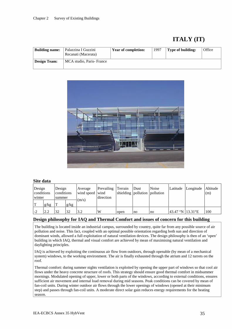
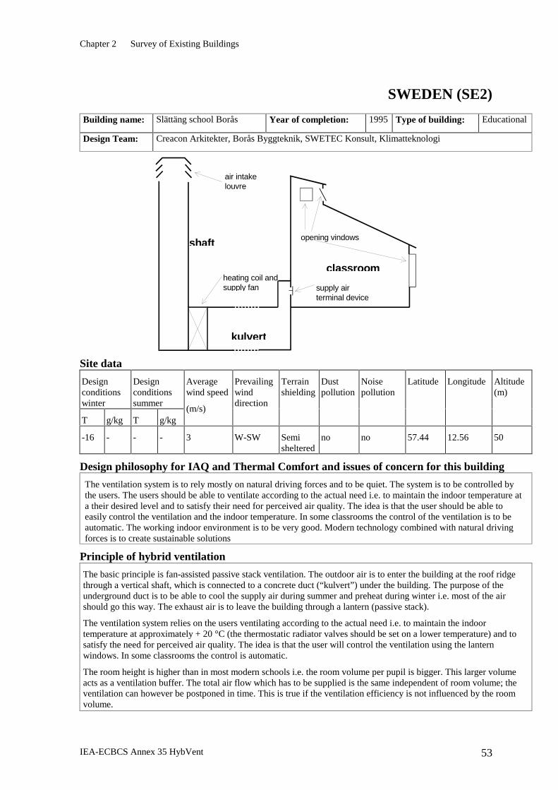
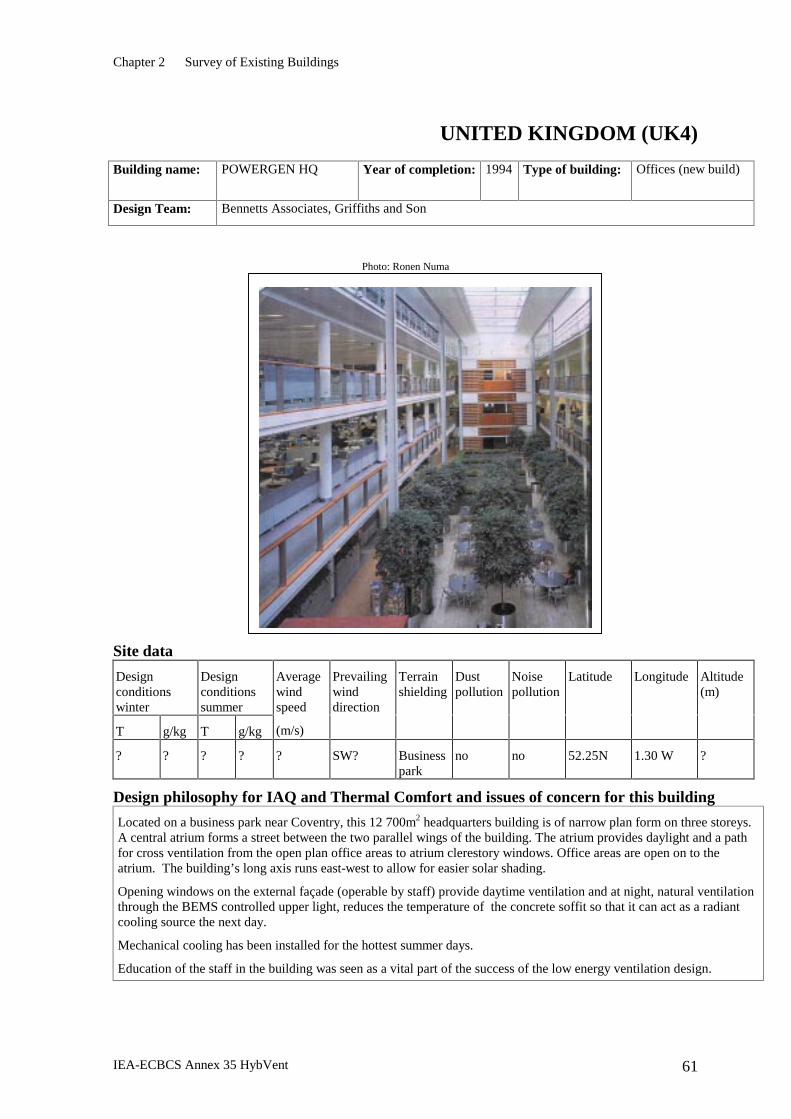
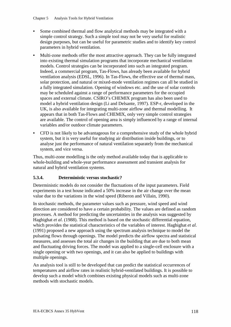
AUSTRALIA (AU1)
Building name: Manly Hydraulics Laboratory (Sydney)
Year of completion: 1998 Type of building: Office
Design Team: Architects and engineers: NSW Department of Public Works and Services, Australia Thermal/ventilation modelling: CSIRO Australia
Site data
Design conditions
winter
Design conditions summer
T g/kg T g/kg
Average wind speed
(m/s)
Prevailing wind
direction
Terrain shielding
Dust pollution
Noise pollution
Latitude Longitude Altitude (m)
7.2 N/A 31.1 14 3.2 E (summer)
W (winter)
Open No No 33° 45’ S 151° 15’ E 25
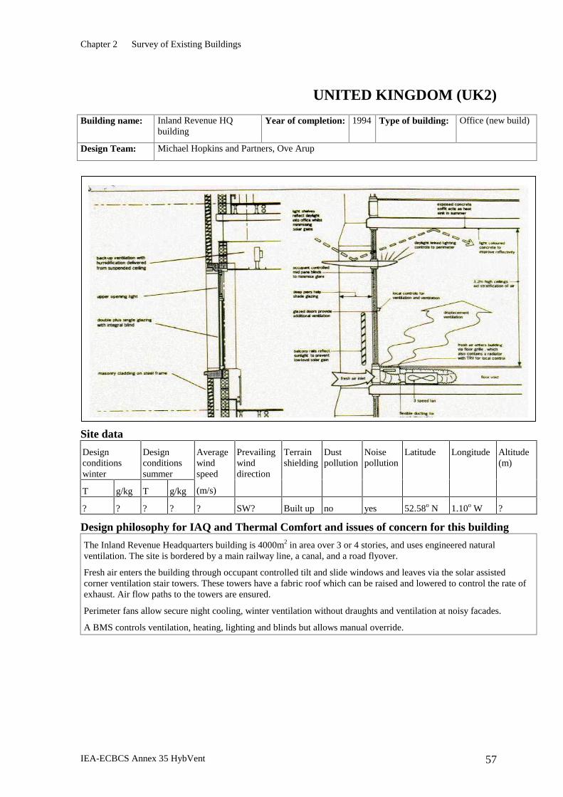
Design philosophy for IAQ and Thermal Comfort and issues of concern for this building
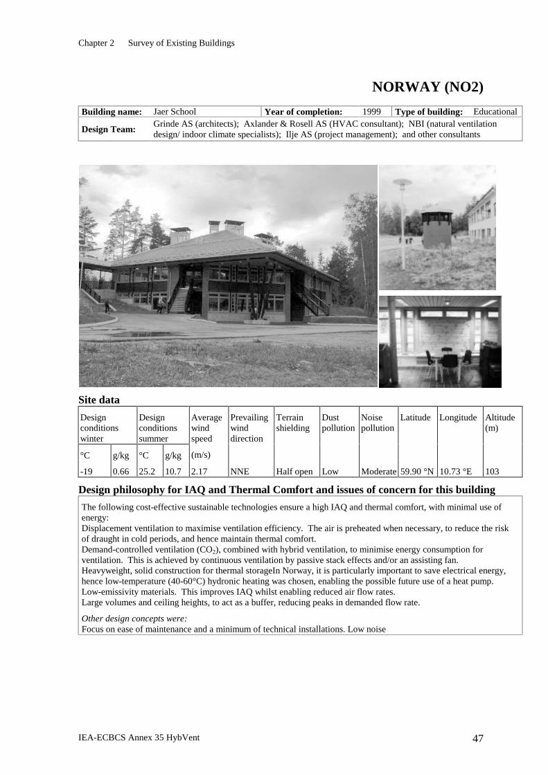
The Manly Hydraulics Laboratory is located in the northern suburbs of Sydney, close to the coast and surrounded by a mixture of natural vegetation and suburban housing. The site is narrow and sloping. The overall design philosophy was to incorporate cost-effective sustainable energy solutions. These included natural ventilation; daylighting; energy-efficient artificial lighting, heating and cooling; and renewable energy systems for hot water, electricity and daylighting.
Natural ventilation provides summer comfort for 90% of the building. The potential difficulties of the sloping rocky site were exploited to provide sub-floor plenums for the natural ventilation system. Because the air supply is via floor grilles, the furniture and partitions had to be designed and located so as to minimise any restriction of the air flow through the office areas. The unfavourable orientation of the long boundaries of the site required careful siting of office areas and shading of windows. Access ramps with exposed concrete are located near the north-west façade windows and contribute to passive heating via direct solar radiation in winter, while protecting the office areas from diffuse summer radiation. Heat gain through the roof was controlled by insulating the roof and ceiling and providing a ventilated air gap between them.
Chapter 2 Survey of Existing Buildings
IEA-ECBCS Annex 35 HybVent 20
Principle of hybrid ventilation
There are six occupied office zones, which are openly interconnected. Outdoor air enters six sub-floor plenums and is cooled by contact with the massive floors, ceilings and walls. The walls are arranged to lengthen the flow path and increase the cooling effect. The air then flows into the office spaces through floor grilles and is extracted by six solar chimneys in the roof. Air can also be supplied from manually-operated low-level windows when outdoor conditions are suitable. Night-flush ventilation is supplied by six supply fans in the underfloor plenums and is used to cool the plenums and remove residual heat in the work areas.
Components used to solve main issues or problems
IAQ control Manually-operated low-level windows. In winter the heating system provides the minimum fresh air requirements.
Temperature control Temperature sensors are located outdoors and in the six plenums, office spaces and solar chimneys. Automatically-controlled retractable external venetian blinds are used on the long facades.
Energy conservation High-mass passive solar design with good levels of insulation and shading are used to control heat gains and losses. Daylighting is provided by pyramid-shaped skylights, which use special laser-cut panels. These panels prevent heat gain during the day by deflecting direct sunlight back out but still allow light to enter from low sky angles. Skylights are also built into the solar chimneys. Heating is provided by a very high efficiency gas-fired system which supplies warm air via the same floor grilles that supply ventilating air in summer. A solar hot water system with electric boost is used for domestic hot water.
Ensuring low pressure drops Ventilating air is supplied directly from sub-floor plenums without the use of ducts.
Draught Some draughts from warm air supply in winter alleviated by use of screens to deflect air away from workstations.
Fire regulations Solar chimney dampers fully closed under fire alarm conditions.
Control Strategies
The control system is a combination of centralised control via a Building Management and Control System (BMCS), and local occupant control. The BMCS controls the outside air dampers, the supply air fan, and the solar chimney dampers. The occupants manually open or close the low-level windows when advised by the BMCS. The BMCS also operates the night flush ventilation and other mechanical ventilation and cooling systems, as well as the time control of the lighting system.
The BMCS has six modes of operation – five ventilation modes and one heating mode. The mode used depends on the time of day (and day of week) and the temperatures of the outdoor air and the six underfloor plenums, occupied zones, and solar chimneys. The zone, plenum and outdoor air temperatures are classified into three bands, namely Tzone > 25, 20 ≤ Tzone ≤ 25, Tzone ≤ 20; Tplenum > 20, 18 ≤ Tplenum ≤ 20, Tplenum ≤ 18; Toa > 20, 18 ≤ Toa ≤ 20, Toa ≤ 18. As well the extract chimney and plenum temperatures are compared to the outdoor air temperature. The mode used depends on the relative values of these four temperatures. Depending on the mode, air is supplied to the occupied zones from one of following sources: cooling plenums; open windows; night-flush fans; heating systems.
Overall performance
The building has been occupied for about a year. Overall performance has been satisfactory. Although on hot days the building is quite warm, it is still cooler than outdoors. The first summer did reveal that some fine tuning was required. As a result, the shading has been improved, the solar chimneys modified to increase heat gains and hence air flows, and the fans are used more often to assist ventilation.
Chapter 2 Survey of Existing Buildings
IEA-ECBCS Annex 35 HybVent 21
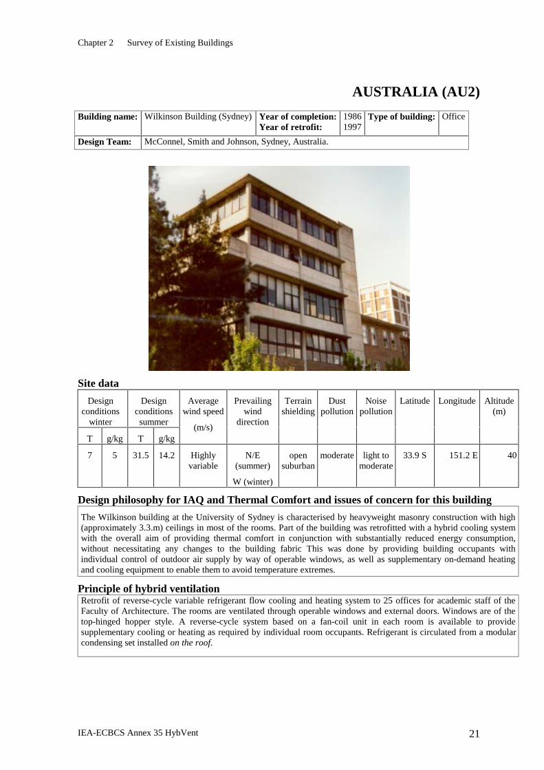
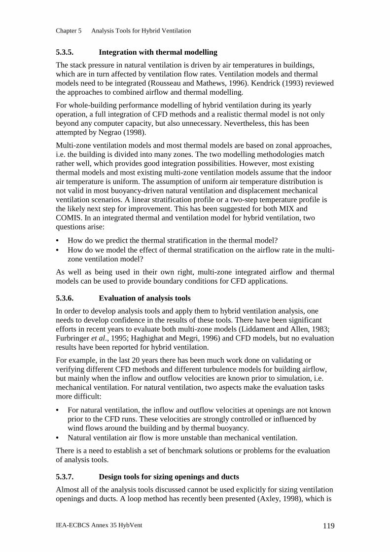
AUSTRALIA (AU2)
Building name: Wilkinson Building (Sydney) Year of completion: Year of retrofit:
1986 1997
Type of building: Office
Design Team: McConnel, Smith and Johnson, Sydney, Australia.
Site data
Design conditions
winter
Design conditions summer
T g/kg T g/kg
Average wind speed
(m/s)
Prevailing wind
direction
Terrain shielding
Dust pollution
Noise pollution
Latitude Longitude Altitude (m)
7 5 31.5 14.2 Highly variable
N/E (summer)
W (winter)
open suburban
moderate light to moderate
33.9 S 151.2 E 40
Design philosophy for IAQ and Thermal Comfort and issues of concern for this building
The Wilkinson building at the University of Sydney is characterised by heavyweight masonry construction with high (approximately 3.3.m) ceilings in most of the rooms. Part of the building was retrofitted with a hybrid cooling system with the overall aim of providing thermal comfort in conjunction with substantially reduced energy consumption, without necessitating any changes to the building fabric This was done by providing building occupants with individual control of outdoor air supply by way of operable windows, as well as supplementary on-demand heating and cooling equipment to enable them to avoid temperature extremes.
Principle of hybrid ventilation Retrofit of reverse-cycle variable refrigerant flow cooling and heating system to 25 offices for academic staff of the Faculty of Architecture. The rooms are ventilated through operable windows and external doors. Windows are of the top-hinged hopper style. A reverse-cycle system based on a fan-coil unit in each room is available to provide supplementary cooling or heating as required by individual room occupants. Refrigerant is circulated from a modular condensing set installed on the roof.
Chapter 2 Survey of Existing Buildings
IEA-ECBCS Annex 35 HybVent 22
Components used to solve main issues or problems
IAQ and Temperature control Operable hopper windows and supplementary on-demand cooling/heating.
Energy conservation Individual fan-coil units in every office supplied by a condensing unit which operates efficiently over a wide range of load conditions.
Control Strategies
Ventilation is controlled by the occupants who open and close windows and doors as appropriate. Occupants of individual rooms choose to operate the supplementary cooling/heating system and to select temperature set-point for the space as desired. The condensing set has a sophisticated control system which adjusts output to match demand to satisfy requirements ranging from a single user through to use in all rooms.
Overall performance
In mild weather, most occupants rely on ventilation through windows or doors to control thermal conditions. Supplementary cooling is used in hot weather in late spring, through summer and into the early part of autumn as required by individual room occupants. The supplementary system tends to default to the ‘off’ mode because deliberate action is required to switch a fan-coil unit on. The system has been in operation since December 1997. Power consumption is less than one third of what would be expected for a conventional air conditioning system with central control. Occupant sensations of thermal comfort and air quality were measured before the supplementary system was installed and again in September. Significant improvements in thermal comfort and air quality indices were recorded.
Chapter 2 Survey of Existing Buildings
IEA-ECBCS Annex 35 HybVent 23
BELGIUM (BE1)
Building name: PROBE (Limelette) Year of completion: Year of renovation :
1975 1997
Type of building: Office
Design Team: Architect (renovation): Y. Wauthy Research & Design: Belgian Building Research Institute ( BBRI – CSTC – WTCB )
Site data
Design conditions winter
Design conditions summer
T g/kg T g/kg
Average wind speed
(m/s)
Prevailing wind direction
Terrain shielding
Dust pollution
Noise pollution
Latitude Longitude Altitude (m)
n.a. n.a. n.a. n.a. 1.8 S-W open no no 50.4 °N 4.31°E 106
Design philosophy for IAQ and Thermal Comfort and issues of concern for this building,
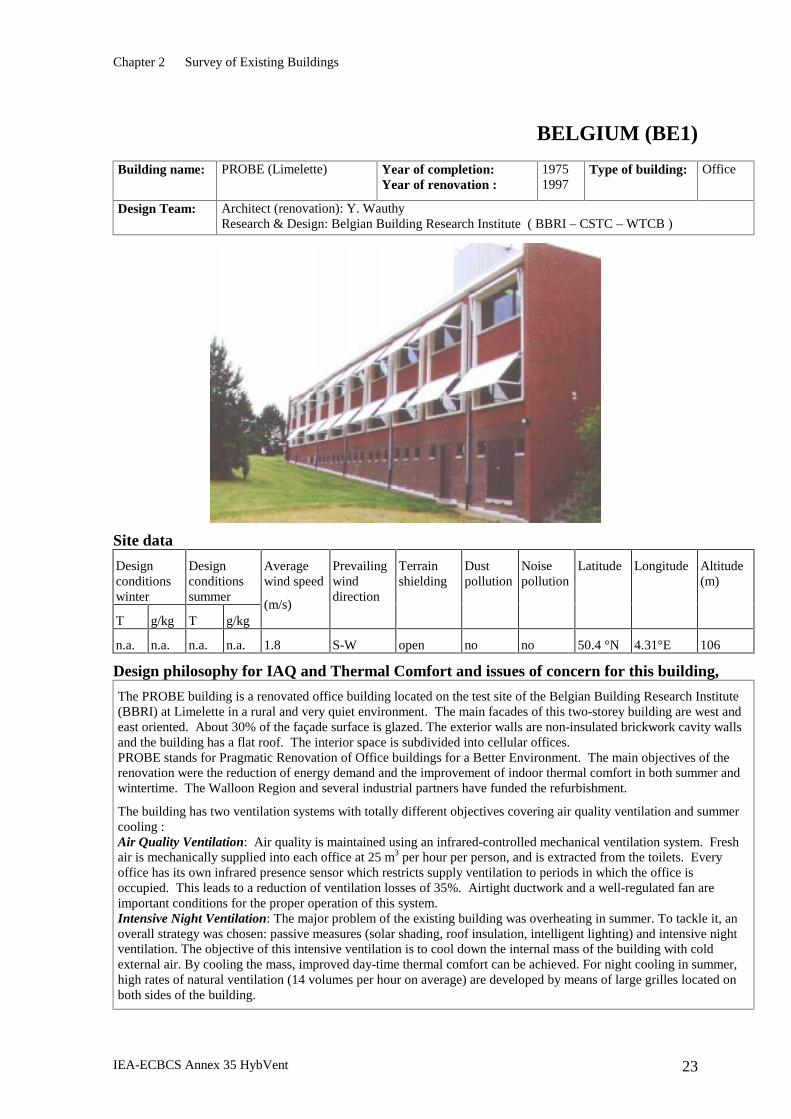
The PROBE building is a renovated office building located on the test site of the Belgian Building Research Institute (BBRI) at Limelette in a rural and very quiet environment. The main facades of this two-storey building are west and east oriented. About 30% of the façade surface is glazed. The exterior walls are non-insulated brickwork cavity walls and the building has a flat roof. The interior space is subdivided into cellular offices. PROBE stands for Pragmatic Renovation of Office buildings for a Better Environment. The main objectives of the renovation were the reduction of energy demand and the improvement of indoor thermal comfort in both summer and wintertime. The Walloon Region and several industrial partners have funded the refurbishment.
The building has two ventilation systems with totally different objectives covering air quality ventilation and summer cooling : Air Quality Ventilation: Air quality is maintained using an infrared-controlled mechanical ventilation system. Fresh air is mechanically supplied into each office at 25 m3 per hour per person, and is extracted from the toilets. Every office has its own infrared presence sensor which restricts supply ventilation to periods in which the office is occupied. This leads to a reduction of ventilation losses of 35%. Airtight ductwork and a well-regulated fan are important conditions for the proper operation of this system. Intensive Night Ventilation: The major problem of the existing building was overheating in summer. To tackle it, an overall strategy was chosen: passive measures (solar shading, roof insulation, intelligent lighting) and intensive night ventilation. The objective of this intensive ventilation is to cool down the internal mass of the building with cold external air. By cooling the mass, improved day-time thermal comfort can be achieved. For night cooling in summer, high rates of natural ventilation (14 volumes per hour on average) are developed by means of large grilles located on both sides of the building.
Chapter 2 Survey of Existing Buildings
IEA-ECBCS Annex 35 HybVent 24
Principle of hybrid ventilation
The ventilation system in the PROBE building is a hybrid ventilation system because a natural (for summer comfort) and a mechanical ventilation (for IAQ) system coexist. Currently, there is no interaction between the two systems - each has its own goals.
In Annex 35, control strategies such as switching from mechanical to natural ventilation during day-time under certain circumstances, will be investigated and implemented.
Components used to solve main issues or problems IAQ control Mechanical ventilation system with infrared presence detection. An interesting feature of this device is that it is completely autonomous (no wiring) so that it is also very well suited for retrofitting projects.
Thermal Comfort: active measures Large grilles for night ventilation, with protection against rain, insects and burglary. The thermal mass must be accessible. In the PROBE building, there is no false floor and no false ceiling.
Thermal Comfort: passive measures Solar shading: vertical external screens, through which only 15% of the solar radiation passes on the west side, and awnings through which 50% of the solar radiation passes on the east side. Insulation (7.5 cm of rockwool) of the roof which reduced the heat gain through solar radiation by 63%. Intelligent lighting: the installed power was reduced from 22 W/m² to 9.5 W/m². Independent integrated luminance sensors are used to dim the lighting according to the luminance level on the desk.
Energy conservation Low-e gas filled double glazing (central U-value = 1,1 W/m².K) and insulated roof. Installation of new fuel boiler and improvement of the regulation system.
Temperature control Thermostatic radiator valves. Control of air flow rate The windows on the east façade can be opened in two different positions.
Control Strategies
Mechanical ventilation is controlled by an infrared presence detection. The user has no way to interfere with it.
Intensive night ventilation: The grilles must be manually opened by the occupants when they leave their office in the evening and (eventually) closed on their arrival in the morning.
Shading devices: Each facade is automatically controlled by a meteorological station according to the prevailing solar radiation, wind, rain and temperature conditions. This control can be manually overruled by the user.
Heating: A thermostat on each side controls the central heating system. The thermostatic radiator valves give the users the opportunity to adjust the heating to their needs.
Overall performance
Monitoring activities during the summer of 1997 and 1998 have shown significant improvement in thermal comfort thanks to the application of the intensive night ventilation strategy, coupled with an efficient control of the solar gains and the reduction of the internal thermal load. It has for instance been measured that the indoor temperature remained below 27°C when the outdoor temperature was above 31°C.
Chapter 2 Survey of Existing Buildings
IEA-ECBCS Annex 35 HybVent 25
BELGIUM (BE2)
Building name: IVEG Year of completion: 1999 Type of building: Office
Design Team: Design Architect: M.Mussche; Consultants: Belgian Building Research Institute Consulting engineers: IVEG and Air-Consult Engineering
Site data
Design conditions winter
Design conditions summer
T g/kg T g/kg
Average wind speed
(m/s)
Prevailing wind direction
Terrain shielding
Dust pollution
Noise pollution
Latitude Longitude Altitude (m)
n.a. n.a. n.a. n.a. n.a. n.a. City Intensive Moderate 51°10’ N 4°22’ E 10
Design philosophy for IAQ and Thermal Comfort and issues of concern for this building
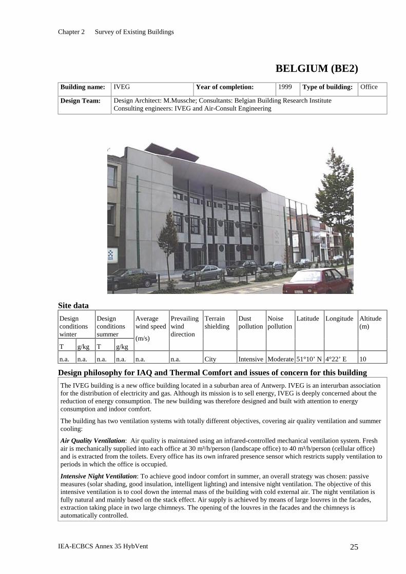
The IVEG building is a new office building located in a suburban area of Antwerp. IVEG is an interurban association for the distribution of electricity and gas. Although its mission is to sell energy, IVEG is deeply concerned about the reduction of energy consumption. The new building was therefore designed and built with attention to energy consumption and indoor comfort.
The building has two ventilation systems with totally different objectives, covering air quality ventilation and summer cooling:
Air Quality Ventilation: Air quality is maintained using an infrared-controlled mechanical ventilation system. Fresh air is mechanically supplied into each office at 30 m³/h/person (landscape office) to 40 m³/h/person (cellular office) and is extracted from the toilets. Every office has its own infrared presence sensor which restricts supply ventilation to periods in which the office is occupied.
Intensive Night Ventilation: To achieve good indoor comfort in summer, an overall strategy was chosen: passive measures (solar shading, good insulation, intelligent lighting) and intensive night ventilation. The objective of this intensive ventilation is to cool down the internal mass of the building with cold external air. The night ventilation is fully natural and mainly based on the stack effect. Air supply is achieved by means of large louvres in the facades, extraction taking place in two large chimneys. The opening of the louvres in the facades and the chimneys is automatically controlled.
Chapter 2 Survey of Existing Buildings
IEA-ECBCS Annex 35 HybVent 26
Principle of hybrid ventilation
The ventilation system in the IVEG-building is a hybrid ventilation system because a natural (for summer comfort) and a mechanical ventilation (for IAQ) system coexist. Currently, there is no interaction between the two systems - each has its own goals. If the intensive night ventilation is not efficient enough to obtain good thermal comfort in summer, it is possible to add a cooling unit to the IAQ ventilation system.
Components used to solve main issues or problems IAQ control Mechanical ventilation system with infrared presence detection.
Thermal Comfort: active measures Intensive night ventilation: Large louvres, with protection against rain, insects and burglary. Large chimney for extraction. The thermal mass must be accessible. In the IVEG-building, there is no false floor. The false ceilings are semi-open. If needed, a small cooling unit can decrease the temperature of the IAQ ventilation air by 2°C.
Thermal Comfort: passive measures Solar shading: vertical external screens. Intelligent lighting: infrared presence detection and independent integrated luminance sensors are used to dim the lighting according to the luminance level on the desk.
Energy conservation Low-e gas-filled double glazing (central U-value = 1,2 W/m².K), well-insulated walls (8cm polystyrene) and roof (10cm foam).
Temperature control Thermostatic radiator valves.
Control Strategies
Mechanical ventilation is controlled by infrared presence detection. The user has no way to interfere with it.
Intensive night ventilation: The control strategy for night ventilation is controlled by a central computer and will be optimised in the framework of IEA Annex 35.
Shading devices: Each facade is automatically controlled by a meteorological station according to the prevailing solar radiation, wind, rain and temperature conditions. This control can be manually overruled by the user as long as the central computer allows it.
Heating: IVEG uses a central heating system with classic radiators and two small condensing gas burners of 60kW each. The thermostatic radiator valves allow users to adjust the heating to their needs.
Overall performance
Monitoring activities are planned in the framework of IEA Annex 35.
Chapter 2 Survey of Existing Buildings
IEA-ECBCS Annex 35 HybVent 27
DENMARK (DK1)
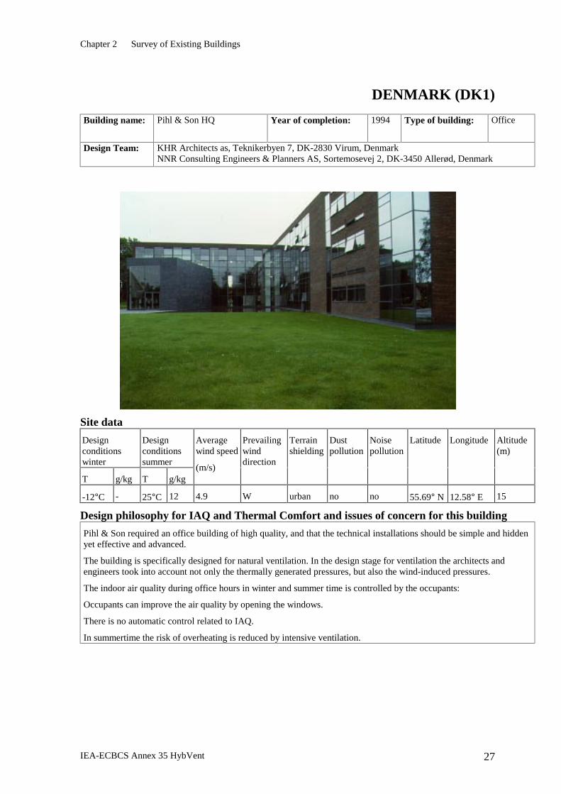
Building name: Pihl & Son HQ Year of completion: 1994 Type of building: Office
-12°C - 25°C 12 4.9 W urban no no 55.69° N 12.58° E 15
Design philosophy for IAQ and Thermal Comfort and issues of concern for this building
Pihl & Son required an office building of high quality, and that the technical installations should be simple and hidden yet effective and advanced.
The building is specifically designed for natural ventilation. In the design stage for ventilation the architects and engineers took into account not only the thermally generated pressures, but also the wind-induced pressures.
The indoor air quality during office hours in winter and summer time is controlled by the occupants:
Occupants can improve the air quality by opening the windows.
There is no automatic control related to IAQ.
In summertime the risk of overheating is reduced by intensive ventilation.
Chapter 2 Survey of Existing Buildings
IEA-ECBCS Annex 35 HybVent 28
Principle of hybrid ventilation
The ventilation principle is stack and wind-driven natural ventilation with fan assistance.
Outdoor air is supplied through specially-designed, high-positioned ventilation windows in the offices and the air is extracted through ventilation openings in the skylights in the skylit galleries.
The intensive ventilation is completely natural and is based on the opening of windows in the facade. Mechanical ventilation is only used in the meeting rooms, toilets, canteen and main foyer.
The windows are partly controlled mechanically and partly controlled automatically.
The intensive ventilation of the offices is based on cross ventilation and single-sided ventilation (when the internal doors are closed). Under certain conditions the vertical skylights open automatically, in which case stack effects are one of the natural driving forces.
During periods when stack effects are not strong enough to drive the natural ventilation regime , two extraction fans on the roof are turned on. Under extreme conditions, the system is fan-assisted.
Components used to solve main issues or problems
Ventilation devices in offices: Specially designed multi-position ventilation openings located in narrow window bands above the ordinary windows, motorised for manual and automatic control.
Ventilation devices in corridors: Openable skylights motorised for both manual and automatic control. Two extract fans: located on the roof integrated with the skylights, intended for use in case the natural driving forces are insufficient.
The control system is based on a I-BUS system, which controls: The ventilation openings using room temperature sensors , the heating system, the artificial lighting and internal solar shading.
Control Strategies
The hybrid ventilation system is automatically controlled by the room temperature when the outdoor temperature exceeds 20°C. For rest of the time, the windows are opened automatically for periods of 10-60 minutes, depending on outdoor temperature. Particular control strategy issues The architecture of the control system is based on centralised components. The ventilation system overrules the heating system and rain or strong winds overrules the ventilation system. Fans can be used for assistance during summer and at night for passive cooling. Individual opening of windows by user interaction is possible. The building management is carried out by internal staff.
Overall performance
Indoor air is generally fresh, odourless and with a high acceptability both summer and winter.
Medium thermal comfort is perceived during summer due to limited shading devices for the large glazed facades and some problems with the control system. During winter it is more comfortable.
The occupants are generally satisfied with their indoor environment. The occupants on the ground floor - in the open plan office - complain about disturbing noise generated on the upper floors. The reception, located on the ground floor in the two-storey foyer, complains about draught problems.
Imperfect behaviour of the I-BUS system, mainly concerning the control of internal shading and ventilation openings in the skylit galleries. Occasionally the system was unable to establish an efficient night-time cooling effect, leading to elevated temperatures in some offices from early morning. There is a requirement for more room thermostats and more evenly distributed openings in skylights.
The above information is based on the EU Joule project NatVent and further information and detailed monitoring results are available from this project.
Chapter 2 Survey of Existing Buildings
IEA-ECBCS Annex 35 HybVent 29
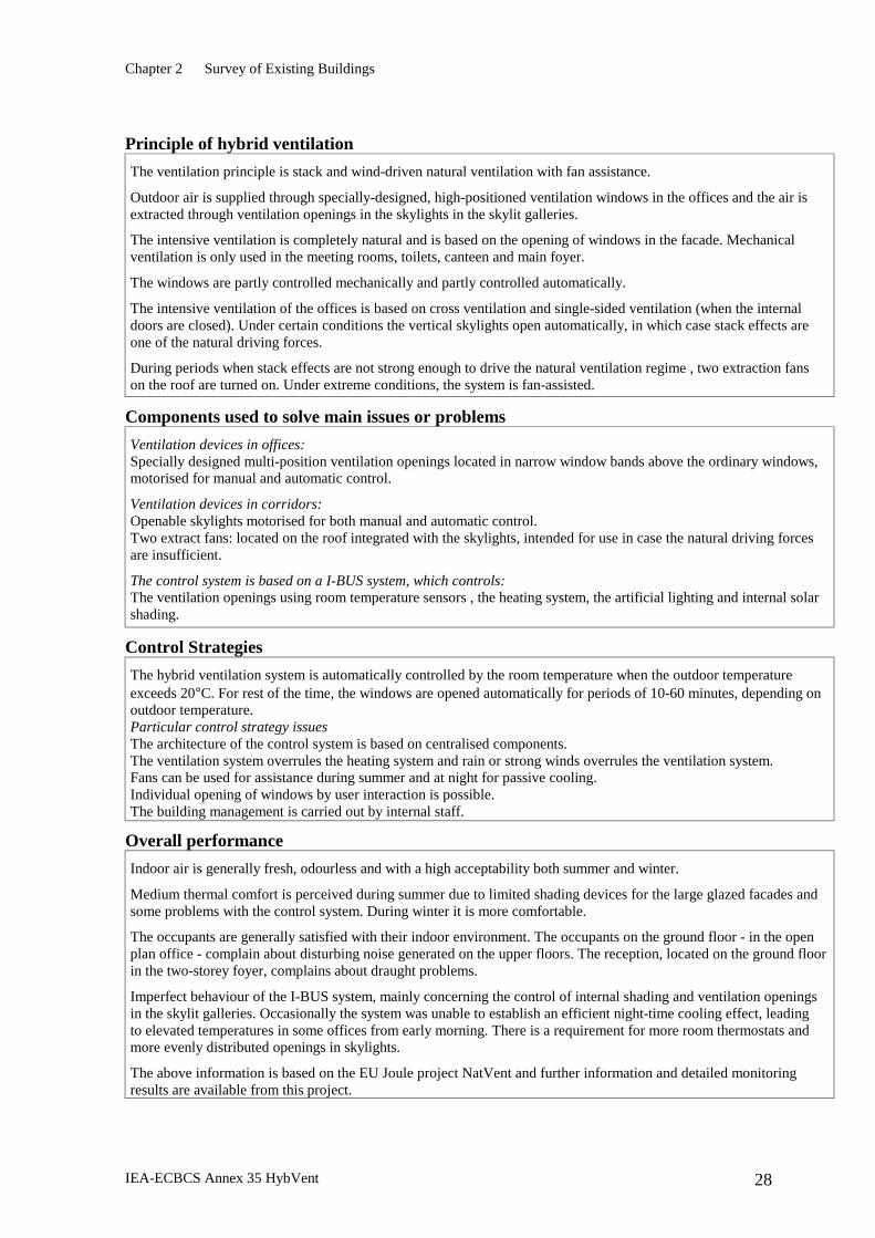
DENMARK (DK2)
Building name: Bang & Olufsen HQ Year of completion: 1998 Type of building: Office
-12°C - 25°C 12 4.9 W open no no 56.42° N 8.58° E 12
Design philosophy for IAQ and Thermal Comfort and issues of concern for this building
Bang & Olufsen required an office building of high quality with a minimum of technical installations, which should be simple and hidden. The office layout is based on an open plan principle. The north facade, which is shown in the above photo, is fully glazed with openings in the horizontal divisions serving as inlets for natural ventilation. The south facade has a moderate window area for daylighting and has user-controlled windows, which are automatically controlled at night to cool the building. Air is extracted through specially-designed cowls on top of the roof, which also has integrated fans to assist the flow when the natural driving forces are insufficient.
The building is specifically designed for natural ventilation. In the design stage for the ventilation the architects and engineers took into account both the thermally-generated pressures as well as the wind-induced pressures. The indoor air quality during office hours in winter and summer is automatically controlled by CO2 sensors. Furthermore, the supply air is pre-heated to a certain level below room temperature to fulfil the requirements of displacement ventilation, which is the air distribution principle. Pre-heating the supply air will also reduce the risk of draught in cold periods, and will therefore lead to improved thermal comfort. The occupants can increase the air change rate by opening the windows, which is done periodically, mainly in summer. In summer the risk of overheating is reduced by use of night time ventilation.
Chapter 2 Survey of Existing Buildings
IEA-ECBCS Annex 35 HybVent 30
Principle of hybrid ventilation
The ventilation principle is stack and wind driven natural ventilation with fan assistance.
The ventilation rates are based on a constant air flow principle to secure an acceptable indoor climate and thermal comfort during office hours.
Outdoor air is supplied and pre-heated through low-positioned ventilation windows at each office floor. The air is extracted through the top of two stairwells, which are openly connected to the offices. Fans to assist the natural driving forces are located at the top of the stairwells.
The design air change rate is 3 ach in summer and 1.5 ach in winter. These air change rates are obtained by natural driving forces and fan assistance based on a constant air flow principle.
Extraction fans are turned on during periods when the stack effect and wind are not strong enough for natural ventilation. Furthermore, the fans will support the neutral pressure level and secure the right direction of the air flow.
Components used to solve main issues or problems
Ventilation devices for supply air: A narrow band of automatically-controlled windows in the glazed north facade. The openings are positioned in the horizontal divisions. Ribbed heat pipes, with inlet temperature sensors, are used to pre-heat the supply air during the heating season. On the south façade, high-positioned daylight windows with actuators are used as supplementary inlet openings.
Ventilation devices for extract air: Two frequency-controlled axial fans at the top of the stairwells. The fans are controlled by air velocity sensors situated in the extracts. Low pressure drop dampers in extract cowls on top of roof. Baffles of sound-absorbent material at the top of the stairwells to reduce the noise level of the fans to a specified low level.
The control system is based on a BEMS system: The hybrid ventilation system is controlled by IAQ using CO2 sensors and room temperature sensors. The ribbed heat pipes at the supply openings are controlled by inlet temperature sensors.
Control Strategies
The hybrid ventilation system is automatically controlled by CO2 level, room temperature or occupancy. The hybrid ventilation system is active according to a certain time schedule or when the building is occupied, with three control modes:
Constant mode based on time schedule or occupancy
CO2 mode based on time schedule and occupancy
Night cooling with fan support based on room temperature
When outdoor temperatures are below 0°C the hybrid ventilation system turns off and occupants can use windows for short time venting. Particular control strategy issues The architecture of the control system is based on centralised components. The position of the valve controlling the heat pipes is used to adjust the inlet openings at the north facade according to variations in wind pressure at different positions of the facade. The ventilation system is overruled by rain or strong winds, which will shut down supply openings in the facades, fans and dampers in the extract. Individual opening of daylight windows at the south facade is possible by user interaction. The building management is carried out by internal staff.
Overall performance
The overall performance will be measured as part of a detailed monitoring program in the Annex 35 project.
Chapter 2 Survey of Existing Buildings
IEA-ECBCS Annex 35 HybVent 31
DENMARK (DK3)
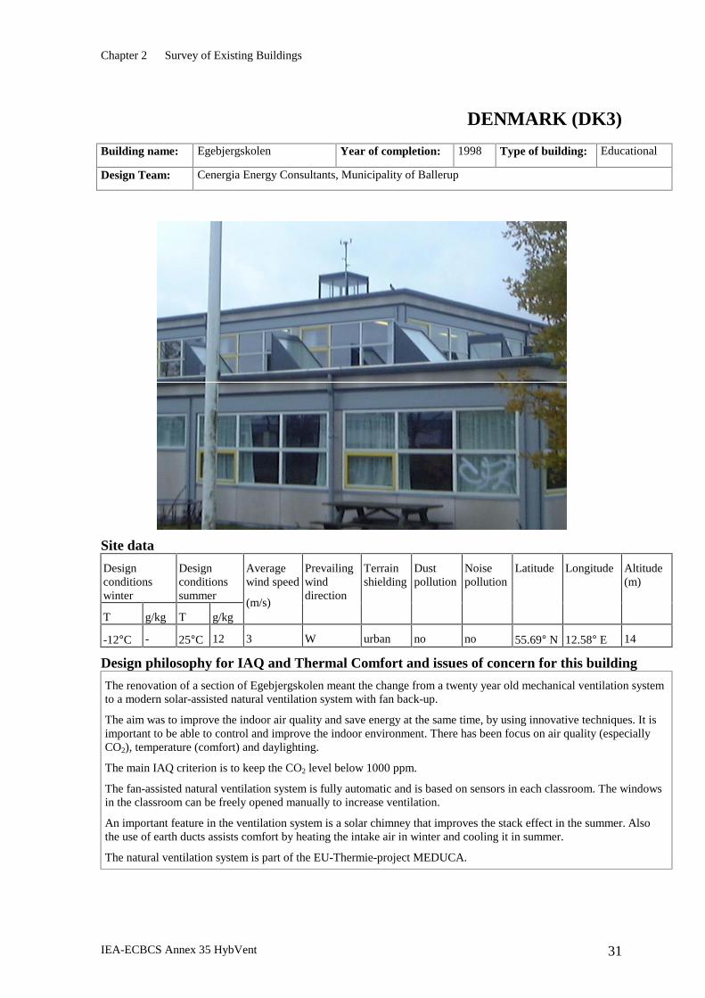
Building name: Egebjergskolen Year of completion: 1998 Type of building: Educational
Design Team: Cenergia Energy Consultants, Municipality of Ballerup
Site data
Design conditions winter
Design conditions summer
T g/kg T g/kg
Average wind speed
(m/s)
Prevailing wind direction
Terrain shielding
Dust pollution
Noise pollution
Latitude Longitude Altitude (m)
-12°C - 25°C 12 3 W urban no no 55.69° N 12.58° E 14
Design philosophy for IAQ and Thermal Comfort and issues of concern for this building
The renovation of a section of Egebjergskolen meant the change from a twenty year old mechanical ventilation system to a modern solar-assisted natural ventilation system with fan back-up.
The aim was to improve the indoor air quality and save energy at the same time, by using innovative techniques. It is important to be able to control and improve the indoor environment. There has been focus on air quality (especially CO2), temperature (comfort) and daylighting.
The main IAQ criterion is to keep the CO2 level below 1000 ppm.
The fan-assisted natural ventilation system is fully automatic and is based on sensors in each classroom. The windows in the classroom can be freely opened manually to increase ventilation.
An important feature in the ventilation system is a solar chimney that improves the stack effect in the summer. Also the use of earth ducts assists comfort by heating the intake air in winter and cooling it in summer.
The natural ventilation system is part of the EU-Thermie-project MEDUCA.
Chapter 2 Survey of Existing Buildings
IEA-ECBCS Annex 35 HybVent 32
Principle of hybrid ventilation
Together with a renovation of Egebjergskolen the original mechanical ventilation system was replaced by natural stack ventilation after the principle of hybrid ventilation. The school is open-plan on one floor level with a crawl space in the basement level below all the classrooms. All the classrooms adjoin the same common room without any partitions between the classrooms and the common room. The common room is of double height. On the roof above the common room is an extract tower. The extract tower includes extract windows and a solar chimney.
The classrooms are supplied with ventilation air from the crawl space. Outdoor air enters the crawl space via earth ducts or a solar wall mounted on a south facade. The air from the crawl space to the classrooms is controlled individually by dampers for each classroom, depending on the CO2 concentration and the room temperature. The exhaust air from the classrooms is evacuated through the common room to the extract tower at the top. When the dampers and windows are open there is very little pressure drop as the air is passes through the building, which gives optimal conditions for passive stack ventilation. If more ventilation is needed a fan will assist the natural ventilation.
The double-height common room in the middle of the building gives good conditions for passive stack ventilation because of the extra height between the air intake and the outlet. Besides stack ventilation, the natural ventilation rate also depends on the wind pressure on the building. The windows in the solar chimney are always open on the leeward side to optimise the wind pressure effect.
Components used to solve main issues or problems
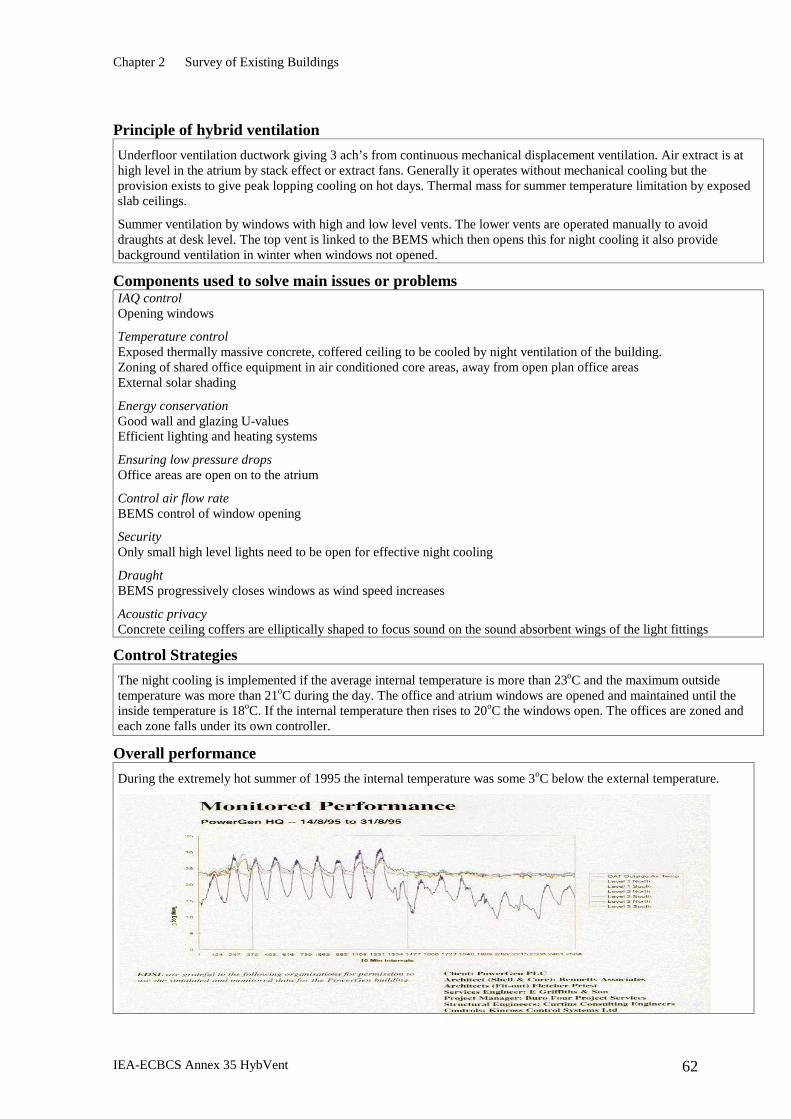
IAQ Control CO2 sensors control the dampers in the classrooms and the windows in the extract tower.
Temperature Control Temperature sensors located in each classroom control the dampers in the classrooms and the windows in the extract tower. The earth ducts precool the intake air in summer.
Energy Conservation The earth ducts preheat the intake air in winter. The effect of the earth ducts is surprisingly high.
Control of air flow rate The windows in the extract tower can open in any direction, but will only be opened on the leeward side. The inlet air is gathered in the crawl space (as in a manifold). Dampers control the flow from the crawl space to the classrooms. The dampers are regulated by the control system. The solar chimney in the extract tower provides extract pressure in summer, when the passive stack pressure is often low. A fan located in the basement provides the required ventilation if natural driving forces are insufficient.
Control Strategies
The control of the natural ventilation is carried out by a building energy management system. The control is based on CO2 and temperature measurements in each classroom. The aim of the control strategy is to ensure high indoor air quality based on demand. Energy savings is the second aim of the control strategy.
The solar chimney opens when the temperature in the chimney is higher than the room temperature.
The ventilation rates are controlled individually in each classroom. The EMS open the dampers gradually depending on the air quality. The dampers open when the CO2 is higher than 700 ppm or when the inside temperature is higher than 23°C. The fan starts gradually when the CO2 is higher than 1400 ppm or when the inside temperature is higher than 25°C. If it rains or the wind velocity is too high the windows will close.
Overall performance
A user survey among children and teachers clearly suggested an improvement of the indoor air quality. The comparison between the natural ventilation system and the existing mechanical ventilation system was easy as only a section of the school had been renovated at the time of the test.
The total yearly energy consumption for heating was 180 kWh/m² before the renovation was carried out. After the renovation the monitored yearly energy consumption for heating was 95 kWh/m² in the renovated part of the school. This means 50% savings for heating energy.
The earth ducts are a very important part of the system. A high degree of preheating of the outdoor air has been recognised with high energy savings. The outdoor air is tempered during summer time.
Chapter 2 Survey of Existing Buildings
IEA-ECBCS Annex 35 HybVent 33
GERMANY (GE)
Building name: Bertolt- Brecht- Gymnasium
Year of completion: 1995 Type of building: Educational
Design Team: IBUS Institut für Bau- Umwelt- und Solarforschung Berlin
Site data
Design conditions winter
Design conditions summer
T g/kg T g/kg
Average wind speed
(m/s)
Prevailing wind direction
Terrain shielding
Dust pollution
Noise pollution
Latitude Longitude Altitude (m)
-15 32 2.5 W city moderate moderate 51.03° N 13.44° E 120
Design philosophy for IAQ and Thermal Comfort and issues of concern for this building
The building is situated within a city terrain. It is a school building of a type which was built very often during the seventies and eighties in the former GDR. The school is a large panel construction. It was originally designed for a maximum use of daylight. All classrooms receive daylight from two sides. During the thermal renovation both courtyards were closed, the windows were replaced, and roof and facade were thermally insulated. Because of the glass roof the good daylight situation was retained.
All class rooms were equipped with a decentralised air ventilation system to ensure good air quality. The operation of the ventilators is, however, left to the user.
To prevent dazzle and excessive summer temperatures, the windows of the south facade are equipped with a movable sun protection.
The basic concept of the design philosophy is the air ventilation coupling of all classrooms to the two atria. Thus summer night cooling is possible, and during the winter the air in the atria can be preheated before being transported into the classrooms.
Chapter 2 Survey of Existing Buildings
IEA-ECBCS Annex 35 HybVent 34
Principle of hybrid ventilation
Hybrid ventilation was introduced in connection with the reconstruction of the building. All classrooms are coupled by ventilation ducts or windows to the atria in the core of the building. The roof of the atria is a glass-steel construction containing windows.
Winter: mechanical ventilation of the classrooms by use of the preheated air from the atria
Summer: Natural ventilation of the classrooms by use of the stack effect in the atria. The same effect is used for night cooling
Components used to solve main issues or problems
Temperature control Thermostat-valves located on all radiators. Temperature control for night cooling (night ventilation) Energy conservation U – value: windows: 1,5 W/m2K; wall and roof: 0,3 W/m2K
Control air flow rate The opening area in the roof can be changed
Draught No complaints are registered in the classrooms; draught registered in the atria at the heating period problem can be solved by changing the value of the opening area (lower windows opening.)
Control Strategies
The Central Control system is programmed with a time schedule. Outside occupied hours the heating and ventilation system is controlled automatically (for night cooling or night heating reduce). During occupied hours the user is responsible for individual manual control. (switches in the classrooms) In case of extreme weather situation (storm, rain) all mechanical. windows will be closed.
Particular control strategy issues The general architecture of the control system is an central management with local sensors in the classrooms. The type of management is internal.
Overall performance
Overall performance of the building is satisfactory. But optimal conditions are not achieved yet. As well as weather data, temperatures for all classrooms, energy consumption and operating times for vents are measured. In addition one atrium and selected class rooms are equipped with special sensors.
Some problems were experienced with the noise of the fans in the classrooms and the acoustic coupling between the atria and the classrooms.
For maintenance, variation of the settings is often too difficult for the local staff.
Chapter 2 Survey of Existing Buildings
IEA-ECBCS Annex 35 HybVent 35
ITALY (IT)
Building name: Palazzina I Guzzini Recanati (Macerata)
Year of completion: 1997 Type of building: Office
Design Team: MCA studio, Paris- France
Site data
Design conditions winter
Design conditions summer
T g/kg T g/kg
Average wind speed
(m/s)
Prevailing wind direction
Terrain shielding
Dust pollution
Noise pollution
Latitude Longitude Altitude (m)
-2 2.2 32 32 3.2 W open no no 43.47 °N 13.31°E 100
Design philosophy for IAQ and Thermal Comfort and issues of concern for this building
The building is located inside an industrial campus, surrounded by country, quite far from any possible source of air pollution and noise. This fact, coupled with an optimal possible orientation regarding both sun and direction of dominant winds, allowed a full exploitation of natural ventilation devices. The design philosophy is then of an ‘open’ building in which IAQ, thermal and visual comfort are achieved by mean of maximising natural ventilation and daylighting principles.
IAQ is achieved by exploiting the continuous air flow from outdoors, through openable (by mean of a mechanical system) windows, to the working environment. The air is finally exhausted through the atrium and 12 turrets on the roof.
Thermal comfort: during summer nights ventilation is exploited by opening the upper part of windows so that cool air flows under the heavy concrete structure of roofs. This strategy should ensure good thermal comfort in midsummer mornings. Modulated opening of upper, lower or both parts of the windows, according to external conditions, ensures sufficient air movement and internal load removal during mid seasons. Peak conditions can be covered by mean of fan-coil units. During winter outdoor air flows through the lower openings of windows (opened at their minimum step) and passes through fan-coil units. A moderate direct solar gain reduces energy requirements for the heating season.
Chapter 2 Survey of Existing Buildings
IEA-ECBCS Annex 35 HybVent 36
Principle of hybrid ventilation
The building provides office accommodation on four floors, located around a central atrium with circulation and service facilities. The main elevation of the building is oriented approximately 12 degrees east of south. Natural cross-ventilation relies on free air flow across the space. Openable panels, located on the south and north glazed facades, and openings on the roof of the atrium provide natural ventilation across the plan. Openings above the atrium consist of twelve skylights with adjustable grilles: the control system opens and closes them depending on the air flow requirement. The total area of openings in the skylights is equivalent to half of the total openings on the facade. Cross-ventilation from the glazed facades to the skylights may be induced by the stack effect or by means of fans installed in turrets on the top of the building. A fan-coil unit in each room is available to provide supplementary cooling or heating when required.
Components used to solve main issues or problems
IAQ Control is based on information coming from CO2 sensors.
Temperature control Thermostat located by each working area.
Energy conservation Insulated and ventilated walls on east and west facade, low-transmittance selective glazed surfaces on south and north facade.
Control of air flow rate Two-step mechanically-opened windows; each window can be opened in different position. Opening of 12 grilles in turrets on the roof; each grille can be opened independently.
Acoustic privacy Problem is still open: some meeting and heads’ rooms require a special acoustic privacy, designers are going to install ducts and mechanical ventilation in these rooms.
Control Strategies
The Central Control system responds to a variety of internal and external conditions. A time schedule should be provided to define when the building is occupied and, if it is occupied, openings may be set to the open or closed position by the central control system. According to IAQ and thermal comfort requirements, the natural ventilation mode operates if the ambient temperature is less than Ti-2°C. In the unoccupied mode the building should operate to allow ventilation to store cool within the mass.
Particular control strategy issues The architecture of the control system is based on a central management system with local sensors at each working seat: a thermostat controls the local temperature as required by individual zone occupants. Occupants may set local temperature in a range (± 2°C) around the temperature defined by Central control system. The type of management is internal at present; a remote connection with external management service will be installed.
Overall performance
The I Guzzini Building is being evaluated during the winter 1998 - autumn 1999 period with respect to thermal comfort, energy consumption and ventilation performance. Moreover evaluations will be made by means of a specific questionnaire distributed to occupants. Some draught complaints have been registered, depending on occupants’ sensitivity; the problem is being solved by mean of a new (at minimum level) setting of lower windows opening.
Chapter 2 Survey of Existing Buildings
IEA-ECBCS Annex 35 HybVent 37
JAPAN (JP1)
Building name: The Liberty Tower of Meiji University, Japan
Year of completion: 1998 Type of building: Educational
Design philosophy for IAQ and Thermal Comfort and issues of concern for this building
With the natural ventilation system, the automatically-controlled ventilation windows are open when the outdoor air is thermally comfortable enough. Because of the large air volume of fresh outdoor air obtained by natural ventilation, and because fresh air is supplied upward from openings under windows, IAQ is improved.
With the mechanical air-conditioning system (when natural ventilation is not functioning because the outdoor air is not comfortable enough), the supplied air flow rate is controlled by a VAV system, and the mixed air volume of fresh outdoor air is automatically controlled based on indoor CO2 concentration for energy savings and IAQ.
Chapter 2 Survey of Existing Buildings
IEA-ECBCS Annex 35 HybVent 38
Principle of hybrid ventilation
During the design process of the building, several testing methods were carried out to test the efficiency of the various components used in the principle of hybrid ventilation system design. The “wind-floor” concept, whereby the central core is designed as a stack-effect to induce natural ventilation at each floor, is the special design feature of the building. The various other measures taken to improve the quality of indoor environment include the use of automatically controlled natural ventilation windows during night time, an automatic outdoor air intake, and a proper building environment and energy management system that takes advantage of the optimum outdoor air quality and temperature to cut energy consumption costs of the building.
Components used to solve main issues or problems
IAQ control: CO2 sensors to control the air volume of mixed outdoor fresh air
Temperature control: temperature sensors positioned in a room or zone area.
Energy conservation: BEMS.
Control of airflow rate: VAV system controlled by BEMS (mechanical air-conditioning system). Windows are automatically controlled (natural ventilation system).
Security: Natural ventilation openings are small enough to prevent invasion. They are covered by steel net to protect against birds.
Acoustic privacy: Silencers between each room and corridor
Fire regulations: smoke sensor
Maintenance: periodical inspection and supervision by BEMS
Control Strategies
Automatically controlled natural ventilation windows and wind floor design (18th floor).
Automatic outdoor air intake control system based on CO2 sensor.
Building environment and energy management system.
The general architecture of the control system is a centralised supervisory control. In principle, operation is by the centralised system.
The type of management is internal.
Overall performance
The use of the natural ventilation system reduces the cooling energy of the building considerably, ranging from 90% in April (Spring) through to a minimum of 6% in July (Summer), and continues to reduce cooling to around 62% in November (Autumn). The wind floor design at the 18th floor, incorporating the automatically-controlled ventilation windows at each of the other lower floors, increases the ventilation rate by 30%.
The overall performance of the building, based on the hybrid ventilation system on top of the optimisation of the building shape to obtain the advantage of the solar geometry, managed to achieve the following savings in energy consumption :
Coefficient of Energy consumption for air conditioning : 52% of Japanese Codes
Coefficient of Energy consumption for ventilation : 52% of Japanese Codes
Chapter 2 Survey of Existing Buildings
IEA-ECBCS Annex 35 HybVent 39
JAPAN (JP2)
Building name: Tokyo Gas Earth Port Year of completion: 1996 Type of building: Office/ showroom/ cooking school
Design philosophy for IAQ and Thermal Comfort and issues of concern for this building
With the natural ventilation system, the automatically controlled ventilation windows are open when the outdoor air is thermally comfortable enough. Because of the large air volume of fresh outdoor air obtained by natural ventilation, IAQ is improved.
With the mechanical air-conditioning system (when natural ventilation is not functioning because the outdoor air is not comfortable enough), the supplied air flow rate is controlled by a VAV system, and the mixed air volume of fresh outdoor air is automatically controlled based on indoor CO2 concentration for energy savings and IAQ.
Chapter 2 Survey of Existing Buildings
IEA-ECBCS Annex 35 HybVent 40
Principle of hybrid ventilation
In the design process of this building, testing methods like thermal dynamic simulations of natural ventilation were carried out to test the efficiency of the various components used in the principle of hybrid ventilation system design of the building.
The various measures taken to improve the quality of indoor and outdoor environment include the automatically controlled natural ventilation windows, atrium “ecological core”, and ventilation tower, taking advantage of the optimum outdoor air quality and conditions at any time, to cut energy consumption costs of the building. Post-occupancy evaluations were carried out at various stages to analyse the energy consumption trends of the building, regular maintenance meetings are being held between residents, the maintenance body and architects to reflect on the operation, fault-detecting devices were installed and counter-measures implemented where necessary.
Components used to solve main issues or problems
IAQ control: CO2 sensors to control the air volume of mixed outdoor fresh air
Temperature control: temperature sensors positioned in a room or zone area.
Energy conservation: BEMS.
Control of airflow rate: VAV system controlled by BEMS (mechanical air-conditioning system). Windows are automatically controlled, and airflow rate by natural ventilation is controlled by the rate of openings of the windows (natural ventilation system).
Fire regulations: Smoke sensor. The natural ventilation windows are opened automatically at the fire to exhaust the smoke
Maintenance: periodical inspection and supervision by BEMS
Control Strategies
Introduction of the Ecological core and ventilation tower using the concept of natural ventilation.
Automatic outdoor air intake control system based on CO2 sensor.
Building environment and energy management system.
The general architecture of the control system is centralised supervisory control.
Occupant interface is via an operation switching panel in each room. Operations by the occupants are learned by the BEMS.
The type of management is internal.
Overall performance
The use of a natural ventilation system utilising design features like the “Ventilation Tower” and the atrium “Ecology Core”, reduced the energy required for ventilation and cooling/heating considerably. The overall performance of the building, based on the hybrid ventilation system on top of the optimisation of the building shape to obtain the advantage of the solar geometry, managed to achieve the following savings in energy consumption :
Coefficient of Energy consumption for air conditioning : 77% of Japanese Codes
Coefficient of Energy consumption for ventilation : 77% of Japanese Codes
Chapter 2 Survey of Existing Buildings
IEA-ECBCS Annex 35 HybVent 41
JAPAN (JP3)
Building name: Fujita Technology Development Division
Year of completion: 1999 Type of building: Laboratory
Design philosophy for IAQ and Thermal Comfort and issues of concern for this building
Perimeter zone thermal control method : solar radiation shading by motor blind controlled by BEMS.
Perimeter air conditioning system composed of perimeter counter with fan coil unit and ceiling exhaust system.
An air curtain system between office floors and atrium is adopted to give a sense of spaciousness.
Excess air supplied to offices is exhausted from upper openings of atrium.
The set up temperature in offices is changed by intra-net occupant vote system linked to the BEMS.
Chapter 2 Survey of Existing Buildings
IEA-ECBCS Annex 35 HybVent 42
Principle of hybrid ventilation
Office building: The natural ventilation system is used to save air-conditioning energy in spring (from April to June) and autumn (from September to November). When natural ventilation is active the air conditioning systems do not operate. At night the ventilation windows are opened to cool the wall and floor of the building by use of the temperature difference between the room air and outdoor air. There is no wall between the office and atrium.
Experiment yard : This large space has no air-conditioning system, in order to save energy. Throughout the year, outdoor air that has passed through underground pits is supplied from the openings installed in walls.
Components used to solve main issues or problems
Temperature control : Temperature sensors positioned in a zone area of 162 m2 (18m x 9m) dividing one floor into 4 zones. Air conditioning system controlled by BEMS.
Energy conservation : BEMS
Control of air flow rate: VAV system controlled by BEMS
Security: ID card system
Fire regulations: Smoke sensor
Maintenance: periodical inspection
Control Strategies
The motor-driven apparatus of the upper part of the window is controlled by the BEMS.
Window operation is controlled by the wind speed, outdoor air temperature and rainfall sensors. Future measurement results will be used to develop detailed window operation rules.
The general architecture of the control system is centralised supervisory control.
Interface with the occupants is via an Intra-net home page style occupant vote system linked to the BEMS.
The type of management is internal.
Overall performance
There is no information. We will confirm the performance by measurement.
Chapter 2 Survey of Existing Buildings
IEA-ECBCS Annex 35 HybVent 43
THE NETHERLANDS (NE)
Building name: NIWI Amsterdam Year of completion: 1997 Type of building: Office
Design Team: Van Rijn†, Rijksgebouwendienst Arnhem - The Netherlands
Alusta autoflow 2000 system. Inlet devices with controlled air supply
Individual control with infrared transmitter Central control with basic unit
Site data
Design conditions winter
Design conditions summer
Average wind speed
(m/s)
Prevailing wind direction
Terrain shielding
Dust pollution
Noise pollution
Latitude Longitude Altitude (m)
T g/kg T g/kg
-7 na 28 n/a 5 SW urban no moderate 52.22 4.8 0
Chapter 2 Survey of Existing Buildings
IEA-ECBCS Annex 35 HybVent 44
Design philosophy for IAQ and Thermal Comfort and issues of concern for this building
The application of a natural ventilation system with the possibility of personal influence on the work atmosphere.
Good distribution of ventilation between offices at the windward side and leeward side.
The aim is to obtain a substantial energy saving, due to controlled air flow rates.
Besides the natural exhaust in the central atrium, extract fans have been applied to secure sufficient airflow rates under all conditions.
Principle of hybrid ventilation
The building has two floors which have cellular office rooms at the facade and an open atrium in the centre. The natural air inlets in each room consist of constant-flow, self-regulating trickle ventilators (Alusta autoflow 2000 system). Each office has an acoustically insulated overflow above the office door, connected to the atrium. In the roof of the atrium there are three natural exhaust chimneys and three mechanical extract ventilators. The design principle is based on a natural exhaust under normal conditions. If the temperature in the atrium is too high, the natural exhaust chimneys are closed and the mechanical ventilators are switched on. Besides air inlet by trickle ventilators, each room has several small openable windows for extra ventilation.
Components used
The Autoflow 2000-system consists of electronic self-regulating air inlets. Controlled air supply means that the air inlet keeps the capacity corresponding to one Pascal pressure difference constant, independent of the actual pressure difference. To let the air inlet control at one Pascal, electronic components are included, which register the actual air velocity. The inlets are acoustically insulated, which results in a low noise level in the offices from outside.
The air inlets are interconnected, which results in a network that is connected to a basic unit. This allows it to serve different parts of the building separately. The basic unit is controlled with a clock.
The self-regulating air inlets have an individual remote control or a sophisticated switch. This makes it possible for the individual user to adjust the position of the air inlets in three different positions. To avoid draught in the office area, the inlets are situated above a false ceiling.
The exhaust consists of three natural exhaust chimneys and three mechanical extract ventilators. The chimneys are provided with a valve to avoid air inlet through these chimneys. With mechanical ventilation these valves are closed. The chimneys and ventilators are also connected to the central control unit.
Acoustic privacy: Each office room has an acoustical insulated overflow above the office door, in connection with the atrium.
Maintenance: Normal cleaning program (yearly frequency).
Control Strategies
The trickle ventilators in the facade are electronically controlled on a central level and on an individual level per office. During working hours the central control device switches the trickle ventilators to the self-regulating mode. The occupants can overrule the central control, during a specified time. After this the air inlet automatically returns to the self-regulating position. In the north-oriented offices there is sophisticated switching; the south-oriented offices have a infrared transmitter, which is also used for controlling the lighting. In summer all trickle ventilators are opened at night. The exhaust in the atrium is temperature-controlled. During winter the air inlets are closed at night.
Overall performance
To avoid cross transport, the built-in sensor of the autoflow-system air inlets can register the direction of the air velocity. The air inlets are closed automatically whenever the air velocity is 0.05 m/s directed outwards. At this time there are no data available about the energy performance and IAQ of the building. The impression of the building manager is that most occupants are satisfied with the ventilation system. The mechanical exhaust is switched on for most of the working hours.
Chapter 2 Survey of Existing Buildings
IEA-ECBCS Annex 35 HybVent 45
NORWAY (NO1)
Building name: Mediå skole, Grong, Norway
Year of completion: 1998 Type of building: Elementary school
Design Team: Kåre Herstad, Letnes Arkitekter AS,. Karin Buvik, Anne Grethe Hestnes, Øyvind Aschehoug and Barbara Matusiak, SINTEF. Eystein Rødahl and Per Olaf Tjelflaat, NTNU.
Site data
Design conditions winter
Design conditions summer
T g/kg T g/kg
Average wind speed
(m/s)
Prevailing wind direction
Terrain shielding
Dust pollution
Noise pollution
Latitude Longitude Altitude (m)
-23 0.5 22 13 0 - 5 SE & NW In valley Low Low 65 N 11 E 50
Design philosophy for IAQ and Thermal Comfort and issues of concern for this building
The Grong school is a new single-storey building of 1000 m2, designed to accommodate 223 occupants. The glazed envelope area is approximately 300 m2, with a glazing U-value of 1.6 W/m2.K. The maximum ventilation flow rate is approximately 2.8 m3/s.
The goals for quality of the indoor environment are to achieve less than 10% dissatisfied and to avoid exposure that can result in short-term or long-term health risks among the occupants.
Low-emissivity materials, displacement ventilation, demand-controlled ventilation and heat recovery of exhaust air has been applied in order to ensure a satisfying indoor environment combined with the lowest possible energy consumption for ventilation.
Daylighting, using skylights, has been installed for all classrooms to improve the indoor environment and to reduce electric energy consumption for artificial lighting.
Electric energy is, in some countries, more expensive than other alternatives for energy supply to a building. And that price difference is expected to rise in the future. Hence, it has been an issue in this project to save electric energy.
Chapter 2 Survey of Existing Buildings
IEA-ECBCS Annex 35 HybVent 46
Principle of hybrid ventilation
The outdoor climate at the site has temperatures below indoors for 95% of the year. There is no steady wind of acceptable strength on the site. Thus, buoyancy-driven ventilation assisted by fans has been chosen for this project. The building has an exhaust tower that has been designed to utilize wind force when available and to avoid entrance of outdoor air. Hence, heat exchanger units placed in the tower for recovery are expected to show high efficiency. The resulting height of heated air column in the building is about 10 m. The ventilation airflow path through the building is sized to allow for velocities up to around 1 m/s. Hence, components like filter and heat exchanger units are much larger than those used for regular mechanical ventilation systems. To overcome the total pressure drop, frequency-controlled fans are installed at the ventilation intake side and at the outlet. Both fans are expected to run when a large airflow rate is needed, for example for free cooling in summer. In a typical winter scenario, only the supply-side fan is expected to run, and at partial speed. The outside air is led through a 15 m long underground duct before it enters the building. That way, the daily temperature swings of the outside air are dampened, and the need for mechanical cooling is avoided.
Components used to solve main issues or problems
IAQ control: one CO2 sensor located at about 1 m height in each room.
Temperature control: one temperature sensor located at about 1 m height in each room.
Energy conservation: displacement ventilation diffusers, room outlet dampers for demand control and heat recovery from the building exhaust air.
Ensuring low pressure drops: using large cross-section of ventilation ducts and by using large components for air handling
Control of air flow rate: CO2 sensors and temperature sensors to control outlet dampers for each room and supply- and exhaust fan for the building.
Outdoor air pollution : using the intake duct to settle large particles and a subsequent fine-filter (EU7) in the intake airflow.
Draught is avoided as a problem by using low-velocity and low-level diffusers in rooms and by using panel heaters below windows.
Acoustic privacy is ensured by using acoustic ceiling and wall panels in each room, by using specially designed air supply ducts installed in the basement distribution duct and by avoiding direct transmission of noise from the outlet damper of one room to another.
Fire regulations: The amount of combustible material in the intake air duct is kept very low. As long as the control system (BEMS) works, the CO2 detection and the ventilation system will automatically work as an active smoke-control system.
Maintenance is partly carried out and supervised by the school caretaker. Mainly dry cleaning methods are used.
Control Strategies
When the building is unoccupied the ventilation airflow rate is low. As people enter a room, heat and CO2 is emitted from the occupants and to the upper part of the room. A horizontal layer of air with a high CO2-level grows downward and exposes, after some time, the CO2 sensor that is connected to the BEMS. When the CO2 concentration reaches a preset level, the BEMS signals the outlet air damper of the room to open one step at a time. If the damper is fully opened, and the CO2 level at the sensor still is too high, the BEMS signals the fans to increase the speed. The supply and exhaust fans are also regulated in steps, and the two fans are controlled to each other to ensure that rooms are not pressurised compared to the outside at winter conditions. A similar strategy, as used for CO2 control, is also used for temperature control.
The BEMS is a centralised system. An irregular value from a sensor is investigated by the school caretaker and with assistance from experts. Occupants may check indoor climate at a thermometer and at a display on the CO2 sensor.
Overall performance
The BEMS strategy must be fine-tuned after one year of measurements and analysis of the data. With that task completed, and with the basis for design still valid, the annual energy consumption for the building is expected to be around 50,000 kWh. That value includes heating of space and of ventilation air plus electricity consumption.
Chapter 2 Survey of Existing Buildings
IEA-ECBCS Annex 35 HybVent 47
NORWAY (NO2)
Building name: Jaer School Year of completion: 1999 Type of building: Educational
Design Team: Grinde AS (architects); Axlander & Rosell AS (HVAC consultant); NBI (natural ventilation design/ indoor climate specialists); Ilje AS (project management); and other consultants
Site data
Design conditions winter
Design conditions summer
°C g/kg °C g/kg
Average wind speed
(m/s)
Prevailing wind direction
Terrain shielding
Dust pollution
Noise pollution
Latitude Longitude Altitude (m)
-19 0.66 25.2 10.7 2.17 NNE Half open Low Moderate 59.90 °N 10.73 °E 103
Design philosophy for IAQ and Thermal Comfort and issues of concern for this building
The following cost-effective sustainable technologies ensure a high IAQ and thermal comfort, with minimal use of energy: Displacement ventilation to maximise ventilation efficiency. The air is preheated when necessary, to reduce the risk of draught in cold periods, and hence maintain thermal comfort. Demand-controlled ventilation (CO2), combined with hybrid ventilation, to minimise energy consumption for ventilation. This is achieved by continuous ventilation by passive stack effects and/or an assisting fan. Heavyweight, solid construction for thermal storageIn Norway, it is particularly important to save electrical energy, hence low-temperature (40-60°C) hydronic heating was chosen, enabling the possible future use of a heat pump. Low-emissivity materials. This improves IAQ whilst enabling reduced air flow rates. Large volumes and ceiling heights, to act as a buffer, reducing peaks in demanded flow rate.
Other design concepts were: Focus on ease of maintenance and a minimum of technical installations. Low noise
Chapter 2 Survey of Existing Buildings
IEA-ECBCS Annex 35 HybVent 48
Principle of hybrid ventilation
The ventilation is predominantly stack-driven natural ventilation, since the outdoor temperature is below room temperature for most of the year. The aerodynamic exhaust towers exploit wind to create a negative pressure irrespective of wind direction, though this effect is much smaller than the stack effect. Fan assistance is used during periods when the stack effect and wind are not strong enough for natural ventilation. The single fan is placed in the culvert in the basement. Each classroom has its own exhaust tower with a damper to control airflow rate. The building must therefore be satisfactorily airtight in order to achieve the desired ventilation rate and energy efficiency. In summer, supplementary ventilation and cooling may be provided by manually opening windows in the facade.
Components used to solve main issues or problems
IAQ control : Airflow to each classroom is controlled by the motorised weatherproof opposed-blade damper in the room’s ventilation turret. The CO2 sensor in each classroom is placed just above breathing height of the seated kids, about 1 m high. Coarse particles fall from the air in transit thought the long culvert.
Temperature control : A temperature sensor is placed outdoors and in each classroom. The occupants can increase the air change rate by opening the windows, which is anticipated only during summer to prevent overheating. All year round, the culvert system provides the minimum fresh air requirements. Low-temperature hot water radiators provide perimeter heating in winter. A heating battery in the culvert preheats supply air to 15°C when necessary.
Energy conservation : Displacement ventilation diffusers for increased ventilation efficiency. Demand-controlled ventilation where the CO2 set-point is temperature compensated to conserve energy at extreme winter temperatures (Max 1500ppm at –15°C outside, Min 1000ppm at +10°C outside). Motorised dampers in each ventilation stack. Low- �JDV-filled double glazing and well insulated walls and roof. Thermostatic radiator valves. BEMS for better energy management. The underground culvert is ca. 2×2m and 60m long, and has a surface area of well over 300m² high-thermal-mass concrete. The culvert dampens daily temperature swings of the incoming fresh air, reducing the need for preheating, and reducing the need for mechanical cooling; the storage effect is greatest for weekly or monthly swings. The seasonal storage capacity is approx. 3-4000kWh; this comes in addition to significant diurnal storage effect. The room height and volume per pupil is bigger than typical schools. This larger volume acts as a ventilation buffer. Hot water for heating is low-temperature water from oil boiler or electric boiler; the boiler used depends on spot energy price, but there are future plans for a ground-water heat pump.
Ensuring low pressure drops : Using large cross-sections for ventilation ducts and large components for air handling. There is no fine filter or heat recovery battery.
Draughts : Problematic draughts are avoided by using low-velocity supply diffusers and by radiators below windows.
Fire regulations : Solar chimney dampers fully closed under fire alarm conditions.? Smoke/fire alarm system.
Maintenance : Operations & Service manuals tailor-made for the building. The caretaker has periodical inspection and supervision by BEMS. Modern, drier, less chemical-intensive cleaning methods are used.
Control Strategies
The control system is a centralised supervisory control (BEMS). In principle, operation is by the centralised system. The type of management is internal by caretaker, or remotely via modem. There are 4 main operation modes, depending on two bimodal parameters. (1) Preheating needed, (2) Preheating not needed though cooling possibly needed, (A) Day, (B) Night. There is night-time ventilation for pre-cooling in summer.
When the CO2 level or temperature in a room rises above set-point value, the damper opens gradually. If the CO2 level remains above the set-point, then the fan is started. The 1m axial fan is frequency-controlled to maintain constant over-pressure in the culvert. The pressure set-point needs fine-tuning.
Overall performance
The building was completed on time and on budget. The total cost (¼������P²) is above the average for schools (¼ 1460–1830/m²), due mostly to its heavyweight structure instead of wood, though the HVAC system cost (¼�����P²) is slightly below average. A measurement program commenced autumn 1999. The teachers and pupils are very satisfied with the indoor environment. One can notice slight traffic noise from the turrets when fully open.
Chapter 2 Survey of Existing Buildings
IEA-ECBCS Annex 35 HybVent 49
NORWAY (NO3)
Building name: NatVent prototype system at NBI Year of completion: 1998 Type of building: Experimental
Design Team: Staff at Norwegian Building Research Institute (NBI)
Design philosophy for IAQ and Thermal Comfort and issues of concern for this building
This prototype ventilation system with heat recovery was constructed in the laboratory at the Norwegian Building Research Institute (NBI) as part of the EU project NatVent®. The prototype represents a full-scale part of a ventilation system, for instance one wing of an office building with 3 - 4 storeys, with a flow rate for about 40 persons.
The prototype tackles design issues that are typical of urban buildings: Filtration Intake air from high level, not street level Minimising exposure to traffic noise Ceiling-to-ceiling heights can be kept to a minimum, since horizontal ductwork is kept to a minimum As this was a prototype system, aesthetics were not an issue.
Chapter 2 Survey of Existing Buildings
IEA-ECBCS Annex 35 HybVent 50
Principle of hybrid ventilation
The system makes maximum use of available stack pressure and wind. Fan assistance is needed because the total system pressure drop is about 50Pa at the design flow rate of 400 l/s, so natural ventilation alone would be insufficient.
The fresh air intake is a wind scoop, with carefully balanced flaps in each of 4 directional intakes that open only on the intake sides that are facing the wind. The exhaust air is also wind-boosted (wind vane) to create suction. Wind tunnel tests gave a wind coefficient at design flow of 0.6 for both the wind scoop and exhaust.
In this particular application for laboratory ventilation, two fans were needed, one for supply and one for return. However, a typical building would need only the exhaust fan because there would be a lower risk of flow reversal.
Components used to solve main issues or problems
IAQ control : There is an electrostatic filter with a claimed filtration efficiency of 92%. Flow rate is kept constant by automatic control of the fan speed.
Energy conservation : There is run-around heat recovery (between the roof stack outlet and a heating battery in the floor-level supply plenum unit after the electrostatic filter). To maximise the stack pressure, the part of the return duct outside the building is insulated, and the length of supply duct inside the building is likewise insulated. The axial fans are particularly efficient, with a new type of low voltage DC motor. At design flow rate, the fan speed is less than 50% of maximum, to ensure low noise and power consumption.
Ensuring low pressure drops : The pressure drop in the ducts can be about 0.15 Pa/m, which translates to a velocity of 1m/s in 125 mm∅ ducts, 2 m/s in 400 mm∅ ducts, or 4 m/s in 1000 mm∅ ducts. The system’s approximate total pressure loss (corrected for stack effect and flow rate) is as follows:
The fans are automatically controlled to maintain constant 400 l/s volume flow rate, based on signals from in-duct anemometers.
Overall performance
Continuous measurements of temperatures, heat recovery efficiency, filter efficiency, airflow, pressure drops, electrical consumption of the fans, wind velocity, and wind direction, have so far lasted 1 year, and will be continued after further optimisation of the system. The volume flow rate is a constant 0.4 m3/s. The total pressure drop for the system (supply and exhaust) is about 50Pa. It should be possible to reduce this to 10-20 Pa by improving known bottlenecks, particularly on the supply side.
If the laboratory hall had been tight, one fan would have been sufficient. However, a second assisting fan was installed to prevent flow reversals in the stacks when the loading bay door into the laboratory is opened. Each fan’s power ranges between 18W and 37W depending on the strength of the available driving forces. With the two assisting fans running at 28W each, on average, the specific fan power (SFP) is 0.14 kW·s/m3, which is about 5% of a typical mechanical ventilation system today.
The heat exchanger efficiency was approx. 50%. This could be improved to about 56% by simple measures. The installation cost was ¼ 29133 or ¼ 72800 s/m3 in 1998. The anticipated costs of an improved future system are about 30% more expensive than a conventional Norwegian system. Annual running costs are approx. ¼ 1700 s/m3, which is considerably less than conventional systems.
The above information is based on the EU Joule project NatVent® and further information and detailed monitoring results are available from this project. More information is available on the NatVent CD-ROM and on-line ( http://www.caddet-ee.org/nl_html/994_07.htm )
Chapter 2 Survey of Existing Buildings
IEA-ECBCS Annex 35 HybVent 51
SWEDEN (SE1)
Building name: Hökegård school Gothenburg
Year of completion: (1964) 1997 Type of building: Educational
Design Team: CNA Architect Offices; EFEM Architect Offices; Anderson & Hultmark HVAC Consultants; Swedish National Testing and Research Institute
Site data
Design conditions winter
Design conditions summer
T G/kg T g/kg
Average wind speed
(m/s)
Prevailing wind direction
Terrain shielding
Dust pollution
Noise pollution
Latitude Longitude Altitude (m)
-16 - - - 3 W-SW open normal normal 57.42 11.58 30
Design philosophy for IAQ and Thermal Comfort and issues of concern for this building
The overall use of electricity for ventilation is to be reduced by installing a demand control system and combining natural (clerestory) and mechanical driving forces in the ventilation system. The system will basically be an exhaust ventilation system. Window airing is possible. In the classrooms the ventilation system will supply a basic ventilation rate during the lessons and then during the break the ventilation can be forced. The idea is that breaks should take place regularly. CO2 and temperature sensors (integrated with the BEMS) for ventilation control will be installed. These sensors should enable the ventilation rates during the heating season to be lowered by 25 %. The users will be given user-friendly instructions on the possibilities of their interacting with the heating and ventilation system. The outdoor supply air is to be preheated in a ground supply duct.
There is to be no mechanical cooling system. Cooling will be achieved naturally by roof (clerestory) and facade vents and night cooling controlled by the energy management system. To reduce high temperatures caused by sunshine appropriate shading devices will be installed. The daylighting level will be optimised by using skylights (clerestories), glare control, day-lighting reflectors etc. The materials (paint etc) of the interior surfaces will be chosen to optimise the indoor light climate. Energy efficient lighting devices (HF neon tubes combined with presence and daylight detectors) will replace the existing ones.
The main IAQ criterion is to keep the CO2 level below 1000 ppm. This is achieved by continuous ventilation by passive stack effects and/or assisting fans. For thermal comfort the draught criterion is set at a maximum air speed of 0.15 m/s and the air temperature criterion at between 20 and 26oC.
Chapter 2 Survey of Existing Buildings
IEA-ECBCS Annex 35 HybVent 52
Principle of hybrid ventilation
The ventilation system of the Hökegård School in Gothenburg was partly converted from a traditional mechanical ventilation to hybrid ventilation within the EU-Thermie project MEDUCA. Approximately one third of the school was converted to a hybrid ventilation system solution. The air supply is led from the outside to the classrooms through a duct located in the crawl space. The exhaust air is led through the lanterns which have windows on the northern facade for daylight purposes. The lanterns are shown on the roof in the picture. The system has a low pressure drop which allows utilisation of thermal stack effects (passive stack ventilation) during parts of the year. If the air flow rate is too low due to insufficient stack effect, an exhaust fan placed in the ventilation chimney assists the ventilation process. The ventilation strategy of the air intakes in the classrooms is in principle displacement ventilation. Due to the natural variation of the ventilation inlet air and the possibility of opening of windows, the ventilation principle will vary between displacement and normal mixed ventilation.
Components used to solve main issues or problems
IAQ control The control of fan assistance is based on signals from CO2 sensors. The CO2 level is not to rise above 1000 ppm. The system allows switching between automatic and manual operation
Temperature control There are pre-set temperature levels to indicate the need to start the assisting fan.
Energy conservation Variable air volume system, daylight increased by reflectors and roof lights, thermal losses reduced by additional roof insulation and new superwindows (U-value 1 W/m²K).
Ensuring low pressure drops Large ducts and openings are chosen
Control of air flow rate An assisting fan is started in case the CO2 level rises above 1000 ppm; windows can be opened.
Fire regulations Fulfils Swedish regulations
Control Strategies
The control strategy is developed to maintain a good air quality within the classrooms in the control. The assisting fan is either manually or automatically controlled. The fan can be started by hand from each classroom. The automatic control is based on a pre-set CO2 and temperature level, respectively, within the classroom. The control strategy is not developed with respect to optimisation of the energy use.
Overall performance
The Hökegård school is being evaluated during the autumn of 1998/spring 1999 with respect to energy use and ventilation performance. The simulated ventilation performance indicates operation of the assisting fan during approximately 90% of the year. The energy consumption of the school is calculated to be reduced from 200 kWh/m2 to 135 kWh/m2 regarding heating. The electricity use was calculated to be reduced from 25 kWh/m2 to 13 kWh/m2.
There has been some problem with backwards flow through the exhaust air ducts at some weather conditions.
Chapter 2 Survey of Existing Buildings
IEA-ECBCS Annex 35 HybVent 53
SWEDEN (SE2)
Building name: Slättäng school Borås Year of completion: 1995 Type of building: Educational
Design philosophy for IAQ and Thermal Comfort and issues of concern for this building
The ventilation system is to rely mostly on natural driving forces and to be quiet. The system is to be controlled by the users. The users should be able to ventilate according to the actual need i.e. to maintain the indoor temperature at a their desired level and to satisfy their need for perceived air quality. The idea is that the user should be able to easily control the ventilation and the indoor temperature. In some classrooms the control of the ventilation is to be automatic. The working indoor environment is to be very good. Modern technology combined with natural driving forces is to create sustainable solutions
Principle of hybrid ventilation
The basic principle is fan-assisted passive stack ventilation. The outdoor air is to enter the building at the roof ridge through a vertical shaft, which is connected to a concrete duct (“kulvert”) under the building. The purpose of the underground duct is to be able to cool the supply air during summer and preheat during winter i.e. most of the air should go this way. The exhaust air is to leave the building through a lantern (passive stack).
The ventilation system relies on the users ventilating according to the actual need i.e. to maintain the indoor temperature at approximately + 20 °C (the thermostatic radiator valves should be set on a lower temperature) and to satisfy the need for perceived air quality. The idea is that the user will control the ventilation using the lantern windows. In some classrooms the control is automatic.
The room height is higher than in most modern schools i.e. the room volume per pupil is bigger. This larger volume acts as a ventilation buffer. The total air flow which has to be supplied is the same independent of room volume; the ventilation can however be postponed in time. This is true if the ventilation efficiency is not influenced by the room volume.
Chapter 2 Survey of Existing Buildings
IEA-ECBCS Annex 35 HybVent 54
Components used to solve main issues or problems
IAQ control The users manually operate the windows in the lanterns according to their perceived air quality. The BEMS monitors the CO2 level in some classrooms.
Temperature control During the heating season the radiators are controlled by thermostatic radiator valves. The users manually operate the windows in the lanterns according to their perceived thermal comfort. The BEMS monitors the indoor temperature.
Energy conservation Variable air volume system, daylight increased by roof lights, thermal losses reduced by increased roof insulation and low-energy windows.
Ensuring low pressure drops Large ducts and openings are chosen
Control of air flow rate An assisting fan in the underground duct is started if the outdoor temperature is above 14 °C; windows can be opened.
Fire regulations Fulfils Swedish regulations
Control Strategies
The assisting fan is either manually or automatically controlled from the BEMS. The automatic control is based on pre-set temperature levels. The control strategy is not developed with respect to optimisation of the energy use.
The daytime (weekdays between 06.40 and 18.00) operation of the supply fan in the underground duct is controlled according to the following scheme:
The underground duct fan is also used for night cooling, if the outdoor temperature is >10 °C and the indoor temperature is >20 °C, then night cooling will take place according to the following scheme:
Outdoor temperature, °C; fan air flow, % < 10; 40 < 15; 45 < 20; 100 < 20; 100
Night cooling will stop when the indoor temperature is <18 °C
Overall performance
The ventilation and thereby the indoor air quality varies with the weather and the users’ use of the windows in the facade and in the lantern. It is usually possible to arrive at a sufficient ventilation rate.
The supply air flow through the underground duct can, without a supply fan, be low and even go backwards during warm weather.
There is a risk of microbial growth in the underground supply duct during spring and summer. Two important factors are choice of material and cleaning, of which the knowledge today is however insufficient.
An important prerequisite for obtaining a desired ventilation and energy conservation outcome is that the building has a good level of airtightness.
Chapter 2 Survey of Existing Buildings
IEA-ECBCS Annex 35 HybVent 55
UNITED KINGDOM (UK1)
Building name: BRE Environmental Office Year of completion: 1997 Type of building: Office (new build)
Design Team: Fielden Clegg Design, Max Fordham & Partners
Site data
Design conditions winter
Design conditions summer
T g/kg T g/kg
Average wind speed
(m/s)
Prevailing wind direction
Terrain shielding
Dust pollution
Noise pollution
Latitude Longitude Altitude (m)
? ? ? ? ? ? suburban no no 51.40N 0.25W ?
Design philosophy for IAQ and Thermal Comfort and issues of concern for this building
This 2000m2 gross, 3-storey building is sited at the Building Research Establishment near Watford. It has a rectangular floor plan with its long axis running east-west. It has cellular and open plan offices, and a large lecture theatre.
About 45% of the south façade is glazed and has adjustable external shading providing solar and glare control.
Ground and first floor ceilings are formed from a sinusoidal concrete slab – this acts to provide high thermal mass and a channel for air flow deep into the building (and building services). A combination of night cooling, single sided and cross ventilation is used. For still summer days solar ventilation chimneys (fronted with glass blocks) encourage stack ventilation. Fans are also fitted in the chimneys for use when natural driving forces are insufficient.
The second floor, instead of the waveform ceiling and connection to the stacks, has a monopitch roof rising to clerestory glazing at 5m - this creates its own stack effect.
A sophisticated BMS controls ventilation openings, fans, winter trickle ventilation, heating and cooling and lighting in an integrated manner, but also allows occupant adjustment.
Winter ventilation is via the vents opening on to the ducts formed by the concrete waveform ceiling - this acts to pre-heat the air before it reaches the office space.
Chapter 2 Survey of Existing Buildings
IEA-ECBCS Annex 35 HybVent 56
Principle of hybrid ventilation
A combination of single sided, cross, passive stack and fan assisted ventilation is used in the building. The main components of the ventilation system are openable windows and vents, ventilation towers and fans fitted within the ventilation towers to assist air flow for night cooling or peak summer conditions.
The outside air is transferred to deep into the office spaces by means of ducts cast into the concrete ceiling. The ceiling is formed from sinusoidal slabs and the ducts are contained within the troughs of these slabs. This provides a large area of thermal mass to ameliorate the effects of heat gains in the building.
Components used to solve main issues or problems
IAQ control, Control air flow rate BMS which controls window and vent openings and fan assistance in ventilation towers
Temperature control Adjustable external glass louvres for solar control, Night cooling via windows and ventilation tower Sinusoidal concrete ceiling (75mm) with high exposed thermal mass in conjunction with night cooling with outside air If required, the underfloor heating pipes can also cool using water drawn from a 70m borehole.
Energy conservation Predominantly natural ventilation using ventilation towers and opening windows Low energy lighting, complemented by good daylighting design, including external shading with fritted glass louvres which also control glare and can act as variable pitch light shelves. Solar control Efficient under-floor heating system Windows U-values – 1.5W/m2K Wall U-values – 0.3W/m2K
Ensuring low pressure drops Area and BMS control of openings
Control Strategies
A BEMS controls the building and opens and closes windows and vents in response to the need for ventilation and night cooling. The occupants have considerable control over the use of windows and can open or close them as required.
Overall performance
The winter performance shows that comfort conditions are maintained and acceptable air change rates are achieved. The average supply of fresh air being approximately 0.75 ach. This resulted in internal CO2 concentrations of just over 1000ppm.
In the summer fresh air supply rates averaged about 2-3 ach and rates of 10 ach were achieved at times of high internal temperatures. The consequent levels of CO2 were lower than in winter at about 600-800ppm. The internal peak design temperature of 28oC was not exceeded at all and the lower 25oC threshold was only recorded on three occasions.
Chapter 2 Survey of Existing Buildings
IEA-ECBCS Annex 35 HybVent 57
UNITED KINGDOM (UK2)
Building name: Inland Revenue HQ building
Year of completion: 1994 Type of building: Office (new build)
Design Team: Michael Hopkins and Partners, Ove Arup
Site data
Design conditions winter
Design conditions summer
T g/kg T g/kg
Average wind speed
(m/s)
Prevailing wind direction
Terrain shielding
Dust pollution
Noise pollution
Latitude Longitude Altitude (m)
? ? ? ? ? SW? Built up no yes 52.58o N 1.10o W ?
Design philosophy for IAQ and Thermal Comfort and issues of concern for this building
The Inland Revenue Headquarters building is 4000m2 in area over 3 or 4 stories, and uses engineered natural ventilation. The site is bordered by a main railway line, a canal, and a road flyover.
Fresh air enters the building through occupant controlled tilt and slide windows and leaves via the solar assisted corner ventilation stair towers. These towers have a fabric roof which can be raised and lowered to control the rate of exhaust. Air flow paths to the towers are ensured.
Perimeter fans allow secure night cooling, winter ventilation without draughts and ventilation at noisy facades.
A BMS controls ventilation, heating, lighting and blinds but allows manual override.
Chapter 2 Survey of Existing Buildings
IEA-ECBCS Annex 35 HybVent 58
Principle of hybrid ventilation
Displacement ventilation in which warmed air rises to the ceiling above the occupied zone and is ventilated by window openings and/or by the air being drawn across the building and up ventilation towers. The ventilation towers have a roof which can be raised or lowered – by up to a metre – to control the air flow rate. The towers are constructed of glass blocks which allow solar heat gains to assist the ventilation process.
Top floors are ventilated separately by ridge vents and additional storey height.
Perimeter fans are used for winter ventilation, secure night cooling, and ventilation at noisy facades.
Components used to solve main issues or problems
Energy conservation Triple glazing, low U-values for roof, walls
Ensuring low pressure drops Generally open plan design but where cellular offices are needed they have corridors allowing air to get to the tower and fit out screens which stop 200mm below the ceiling. High ceilings
Control air flow rate, IAQ control Ventilation towers, 7m higher than the top floor they serve, built with glass blocks, allowing them to absorb solar energy to enhance the stack effect. Fabric roof can be raised or lowered to control air flow.
Temperature control Mid-pane blinds and external light shelves High efficiency lighting system with daylight dimming Exposed concrete soffit Secure night cooling using perimeter fans BMS controls heating, lighting, ventilation, and blinds, but allows occupant override
Draughts Occupant-controlled fans below floor perimeter to allow windows to be closed in winter or at noisy site boundaries
Acoustic privacy Vaulted ceiling profile avoids acoustic hot spots.
Fire regulations Doors from the office space onto the ventilation towers are kept open by emergency released electromagnet to comply with fire regulations.
Control Strategies
The control strategy allows the BEMS to optimise energy efficiency and allow local control. At specified times during the day the BEMS sets default values for the ventilation rate, perimeter lighting and flow temperature through the radiators to achieve optimum performance. These values can be overridden by manual controls to suit individual preferences.
Night cooling is enable provided the average outside air temperature between 12:00 and 17:00 exceeds 18oC, and: outside air temperature > 12oC inside air temperature > outside air temperature inside air temperature > 15.5oC with 3o C deadband
Overall performance
Internal temperatures, in the lower two floors, during the monitored period (mid-August 1995) remained in the band between 22.5 oC and 26.5oC. However, the top floor performed less well and reached 29oC, although this was in fact 0.5oC less than outside.
Predicted energy consumption for lighting, heating, cooling fans and pumps is 89 kWh/m2/y.
Chapter 2 Survey of Existing Buildings
IEA-ECBCS Annex 35 HybVent 59
UNITED KINGDOM (UK3)
Building name: IONICA Year of completion: 1994 Type of building: Office (New Build)
Design philosophy for IAQ and Thermal Comfort and issues of concern for this building
The Ionica building is located near Cambridge, with a busy road to the north and a sewage works to the north east. The office space is mainly open plan with some cellular offices and meeting spaces to the north, which form a effective buffer, allowing natural ventilation of the open plan offices to the south.
To maximise daylight and provide controllable cross ventilation whist minimising solar gains, the building is orientated with main facades facing N-S, with a central atrium extending through all three storeys to a glazed roof with ventilation wind towers.
It is expected that the building will be naturally ventilated for most of the year with an efficient mechanical system (with heat recovery and evaporative cooling) for mid-winter and mid-summer use. Control for the mechanical periods will be automatic. For the rest of the year the occupants are expected to operate the cross ventilation system and seminars and user instruction sheets have been prepared by the designers to assist the users.
A hollow concrete floor slab allows cooling of the structure at night, mechanically, or in the day with evaporative cooling.
Costs were calculated to be below those for a traditional air conditioned building.
Chapter 2 Survey of Existing Buildings
IEA-ECBCS Annex 35 HybVent 60
Principle of hybrid ventilation
Shading against solar heat gain
Exposed concrete ceiling soffits providing significant thermal capacity, augmented by cooling the floor by passing air through its hollow cores. Its thermal capacity is also used in winter heating.
Displacement ventilation fed from the floor slabs through the raised floors and extracted via the atrium, or via ducts where there is cellular accommodation. Extract from the atrium relies on stack effect promoted by six wind towers at ridge level.
Occupancy can be 24 hours and therefore some cooling is required. Achieved by using outside air when temperatures are suitable – otherwise there is mechanical cooling. The cooled ceiling reduces surface radiant temperatures.
Components used to solve main issues or problems Temperature control, IAQ control, Energy conservation, Control of air flow rate A pre-cast concrete hollow core floor slab (250mm thick) with an in-situ concrete topping is left exposed on its underside with only a paint finish, to absorb heat gains. Interactive façade with controllable external and internal shading, opening low-e insulating windows. Central atrium and wind chimneys designed to be controllable and operate for all wind directions for most of the year. Air handling units with heat recovery and evaporative cooling provide good air quality and controllable low level mechanical ventilation. Fresh air is distributed via the under floor ducts and exhausted through the atrium or corridor (for cellular offices)
Acoustic privacy The suspended light fittings have acoustic baffles.
Maintenance Hollow floor slabs are accessible for cleaning and were dust sealed before installation.
Control Strategies
Winter day – external temperature below 10oC some heating needed to maintain 20-21oC. Full fresh air, heated as necessary- with heat recovery – fed to hollow floors and returns by stack effect or return duct to the AHU. Perimeter electric heating may be used as supplement. Windows permanently closed but can be overridden.
Winter night- ventilation runs to redistribute heat to give a minimum 18oC all night. If not enough heat, perimeter heat used to pre-heat to 20oC for morning start.
Mid-season (most of year) night – window to south opened, cool air drawn over ceiling soffit by stack effect. Mechanical ventilation used in cellular spaces
Mid season day – stack effect natural ventilation and regulated wind tower ventilation.
Summer day – tendency to overheat. Mechanical ventilation through the floors combined with evaporative cooling at the AHU’s with outside air or heatpump cooled air.
Summer night – as mid season night except of outside air is not cool enough mechanical ventilation through the slabs to cool them.
Overall performance
At supply rate of 4-4.5 ach’s the overall cooling capacity of the plank system is estimated at 10-15 W/m2.
Monitoring showed that over a period between January and June 1996 the internal temperature exceeded 27.5oC for only 5 five hours and this was when the external temperature was more than 30oC.
Predicted energy use is 64kWh/m2/y - a 46% improvement on a good practice air conditioned building.
Chapter 2 Survey of Existing Buildings
IEA-ECBCS Annex 35 HybVent 61
UNITED KINGDOM (UK4)
Building name: POWERGEN HQ Year of completion: 1994 Type of building: Offices (new build)
Design Team: Bennetts Associates, Griffiths and Son
Photo: Ronen Numa
Site data
Design conditions winter
Design conditions summer
T g/kg T g/kg
Average wind speed
(m/s)
Prevailing wind direction
Terrain shielding
Dust pollution
Noise pollution
Latitude Longitude Altitude (m)
? ? ? ? ? SW? Business park
no no 52.25N 1.30 W ?
Design philosophy for IAQ and Thermal Comfort and issues of concern for this building
Located on a business park near Coventry, this 12 700m2 headquarters building is of narrow plan form on three storeys. A central atrium forms a street between the two parallel wings of the building. The atrium provides daylight and a path for cross ventilation from the open plan office areas to atrium clerestory windows. Office areas are open on to the atrium. The building’s long axis runs east-west to allow for easier solar shading.
Opening windows on the external façade (operable by staff) provide daytime ventilation and at night, natural ventilation through the BEMS controlled upper light, reduces the temperature of the concrete soffit so that it can act as a radiant cooling source the next day.
Mechanical cooling has been installed for the hottest summer days.
Education of the staff in the building was seen as a vital part of the success of the low energy ventilation design.
Chapter 2 Survey of Existing Buildings
IEA-ECBCS Annex 35 HybVent 62
Principle of hybrid ventilation
Underfloor ventilation ductwork giving 3 ach’s from continuous mechanical displacement ventilation. Air extract is at high level in the atrium by stack effect or extract fans. Generally it operates without mechanical cooling but the provision exists to give peak lopping cooling on hot days. Thermal mass for summer temperature limitation by exposed slab ceilings.
Summer ventilation by windows with high and low level vents. The lower vents are operated manually to avoid draughts at desk level. The top vent is linked to the BEMS which then opens this for night cooling it also provide background ventilation in winter when windows not opened.
Components used to solve main issues or problems IAQ control Opening windows
Temperature control Exposed thermally massive concrete, coffered ceiling to be cooled by night ventilation of the building. Zoning of shared office equipment in air conditioned core areas, away from open plan office areas External solar shading
Energy conservation Good wall and glazing U-values Efficient lighting and heating systems
Ensuring low pressure drops Office areas are open on to the atrium
Control air flow rate BEMS control of window opening
Security Only small high level lights need to be open for effective night cooling
Draught BEMS progressively closes windows as wind speed increases
Acoustic privacy Concrete ceiling coffers are elliptically shaped to focus sound on the sound absorbent wings of the light fittings
Control Strategies
The night cooling is implemented if the average internal temperature is more than 23oC and the maximum outside temperature was more than 21oC during the day. The office and atrium windows are opened and maintained until the inside temperature is 18oC. If the internal temperature then rises to 20oC the windows open. The offices are zoned and each zone falls under its own controller.
Overall performance
During the extremely hot summer of 1995 the internal temperature was some 3oC below the external temperature.
Chapter 2 Survey of Existing Buildings
IEA-ECBCS Annex 35 HybVent 63
2.3. Summary tables of example existing buildings Table 2.1. Building data
ID Name of building Building owner Latitude Longitude Altitude (m)
Year of completion
Address A-35 Contact person
AU1 Manly Hydraulics Laboratory
NSW Department of Public Works and Services, Sydney, Australia
33.75° S 151.25° E 25 1998 King Street, Manly Vale, NSW 2093, Australia
Angelo Delsante
AU2 Wilkinson (G04) University of Sydney 33.9° S 151.2° E 40 Built 1986
Retrofitted 1997
City Road, Sydney 2006, Australia David Rowe
BE1 PROBE (Limelette) Belgian Building Research Institute - CSTC -WTCB
50.4° N 4.31° E 106 Built 1975
Renovated
1997
Avenue P. Holoffe, 21, B – 1342, Limelette, Belgium
Nicolas Heijmans
BE2 IVEG IVEG (Interkomunale Voor EnerGie )
51°10’ N 4°22’ E 10 1999 Antwerpsesteenweg , 260 B-2660 Hoboken, Belgium
Nicolas Heijmans
DK1 Pihl & Son HQ Pihl & Son A/S 55.69° N 12.58° E 15 1995 116, Nybrovej DK-2800 Lyngby Denmark
Ole Juhl Hendriksen
DK2 Bang & Olufsen HQ Bang & Olufsen 56.42° N 8.58° E 12 1998 Peter Bangs Vej 15, DK-7600 Struer, Denmark
Ole Juhl Hendriksen
DK3 Egebjergskolen Municipality of Ballerup 55.69° N 12.58° E 14 1998 Egebjergvang 80, 2750 Ballerup Per Heiselberg
GE Bertolt-Brecht-Gymnasium
City of Dresden Schulverwaltungsamt
51.03° N 13.44° E 120 Built: 1969; retrofitted 1995
Lortzingstr. 1, 01307 Dresden, Germany
Markus Rösler
IT Palazzina "I Guzzini" I GUZZINI Illuminazione srl
NE -7 Not applied 28 Not applied 5 SW Urban No Moderate
NO1 -23 0.5 22 13 0 - 5 SE & NW In valley Low Low
NO2 -19 very low (90%rh)
25.2 10.7 2.17 NNE Open Moderate High (traffic noise)
NO3 -20 very low (90%rh)
25.2 10.7 2.17 NNE Urban Moderate No
SE1 -16 - - - 3 W-SW Open Normal Normal
SE2 -16 - - - 3 W-SW Semi-sheltered No No
UK1 ? ? ? ? ? ? Suburban No No
UK2 ? ? ? ? ? SW? Built up No Yes
UK3 ? ? ? ? ? SW? Open? No Yes
UK4 ? ? ? ? ? SW? Business park No No
Chapter 2 Survey of Existing Buildings
IEA-ECBCS Annex 35 HybVent 66
Table 2.3. Technical information
ID Building height (m)
Number of floors
Dominant load1
Space arrangement
Thermal mass
Design Philosophy for IAQ and temperature control
Components used
AU1 10 (approx.) each section
2 (one occupied + one utility)
Skin Open plan with minor partitioning
Medium Good passive solar design coupled with natural ventilation for IAQ and temperature control; fan assistance if required.
Openable windows; solar chimneys; temperature sensors; fan-assisted sub-floor plenums; draught-deflecting screens
AU2 15 Rooms on 3 floors
Skin Cellular with some multiple occupancy
Heavy Reduce energy consumption by providing occupants with individual control of heating and cooling and outdoor air supply
Openable hopper windows
BE1 6 2 Skin Cellular Heavy Good passive design coupled with intensive night ventilation for temperature control; presence-controlled mechanical ventilation for IAQ control
DK1 About 11 3 Skin Cellular with some open plan and multiple occupancy
Heavy Manual and automatic control of natural ventilation, fan-assisted under extreme conditions
Motorised multi-position ventilation openings; motorised skylights with extract fans; temperature sensors
DK2 14 3 Skin Mainly open plan
Heavy Displacement natural ventilation using pre-heated supply air, fan-assisted to maintain constant flow. Night-time ventilation for summer temperature control.
CO2 and temperature sensors; automatically-controlled windows; frequency-controlled axial fans controlled by air velocity sensors; low pressure drop dampers in extract cowls; sound-absorbing baffles.
DK3 8 1 Skin Open-plan Medium Improve indoor air quality and reduce energy consumption via a modern solar-assisted natural ventilation system with fan back-up
CO2 and temperature sensors; extract tower and solar chimney; individually-controlled inlet dampers; earth ducts; openable windows.
GE 11 4 Core Cellular Medium (700 kg/m2)
Ventilation coupling of all classrooms to atria
Manually openable windows/ventilators
Chapter 2 Survey of Existing Buildings
IEA-ECBCS Annex 35 HybVent 67
Table 2.3 (cont.). Technical information
ID Building height (m)
Number of floors
Dominant load1
Space arrangement
Thermal mass
Design Philosophy for IAQ and temperature control
Components used
IT 13 Open plan Heavy ‘Open’ building in which IAQ, thermal and visual comfort are achieved by mean of maximising natural ventilation and daylighting principles.
CO2 sensors; thermostats; two-step mechanically-opened windows; grilles in roof turrets
JP1 120 B3F-23F Skin Open plan Light Supply large air volumes of fresh outdoor air by natural ventilation. Use of “Wind-floor” concept, whereby the central core is designed as a stack-effect to induce natural ventilation at each floor. When HVAC is used, fresh air proportion is controlled by CO2 sensors.
CO2 sensors; thermostats; automatically controlled windows
JP2 27 4 Skin Open plan Light Supply large air volumes of fresh outdoor air by natural ventilation. Use of atrium “ecological core”. When HVAC is used, fresh air proportion is controlled by CO2 sensors.
CO2 sensors; thermostats; automatically controlled windows; ventilation tower
JP3 18 3 Skin Open plan Light Natural ventilation and night cooling during spring and autumn. Offices opening into atrium via air curtain.
Intra-net occupant vote system linked to the BEMS for setting temperature setpoint; temperature sensors; openable windows; underground cooling pits
NE 8,5 2 Skin Cellular office Heavy Obtain substantial energy savings via controlled air flow rates, with occupant control. Good distribution of ventilation between windward and leeward side offices.
Light Use of low-emissivity materials, daylighting, displacement ventilation, demand-controlled ventilation and heat recovery of exhaust air to minimise electric energy and maximise air quality
CO2 and temperature sensors; low-velocity low-level displacement ventilation diffusers; specially-designed air supply ducts to reduce noise; exhaust tower with heat exchanger; underground duct; supply and exhaust fans
Chapter 2 Survey of Existing Buildings
IEA-ECBCS Annex 35 HybVent 68
Table 2.3 (cont.). Technical information
ID Building height (m)
Number of floors
Dominant load1
Space arrangement
Thermal mass
Design Philosophy for IAQ and temperature control
Components used
NO2 12 to roof apex (stacks are 13.5 m above ground level)
2 Skin Combi Medium/ Light
Use of cost-effective sustainable technologies to ensure a high IAQ and thermal comfort, with minimal use of energy, including displacement ventilation, demand-controlled ventilation, heavyweight construction, low-emissivity materials
Underground culvert; temperature & CO2 sensors; motorised dampers in each ventilation stack
NO3 Approx. 7 to roof (stacks 16.5m above ground level)
3 Skin Open N/A Prototype designed to tackle typical design issues such as filtration, high-level intake air, minimising exposure to traffic noise, keeping ceiling heights to a minimum
Motorised dampers in directional intakes; roof-mounted wind-boosted exhaust; supply and exhaust fans; run-around heat recovery; electrostatic filter and very coarse prefilter
SE1 7 1 Skin Cellular Heavy To maintain the CO2 level below 1000 ppm, the air speed below 0.15 m/s and air temperature between 20 and 26°C, using a demand-controlled ventilation system combining natural and mechanical driving forces.
CO2 and temperature sensors; fan-assisted roof lanterns for exhaust and daylighting; openable windows; ground supply duct
SE2 7.5 1 Skin Cellular Heavy Users to be able to easily control ventilation for IAQ and temperature control, relying mostly on natural driving forces.
Underground culvert with fan assist; manual/automatic lantern exhausts; CO2 sensors; large ducts and openings
UK1 ~15 3 Skin Open Heavy Combine single-sided, cross, passive stack and fan-assisted ventilation. Supply air via ducts cast in high-mass exposed ceilings.
Openable windows and vents; fan-assisted ventilation towers
UK2 14.4 3 Skin Open Heavy Natural displacement ventilation system. Solar-assisted ventilation towers with ad-justable roof ; openable windows; underfloor fans; reduced-height partitions and screens.
UK3 15.5 3 Skin Open Heavy Natural displacement ventilation system. High-mass ceilings to limit temperature swings
Wind towers or ducts for exhaust; hollow-core concrete floor fed by supply air; openable windows
UK4 N/a 3 Skin Open Heavy Mechanical displacement ventilation. High-mass ceilings to limit temperature swings
Fan-assisted atrium for exhaust; windows with high (automatic) and low (manual) level vents; underfloor ventilation ductwork
Note 1. “Dominant load” refers to the relative importance of the skin loads (conduction and solar gains) versus core loads in the design.
Chapter 3 Critical barriers to hybrid ventilation
IEA-ECBCS Annex 35 HybVent 69
3. CRITICAL BARRIERS TO HYBRID VENTILATION Barriers to natural ventilation systems have been investigated in previous projects, in particular the AIOLOS project (Allard, 1998) and the NatVent project (Aggerholm, 1998a, 1998b).
The AIOLOS project was carried out within the framework of the ALTENER Programme of the European Commission, Directorate General XVII, for Energy. The goal of the AIOLOS project “… was to create specific educational material on the efficient use of passive ventilation for buildings that can be transferred to all education activities and can be used by all the professionals involved in the design of buildings” (Allard, 1998).
NatVentTM was an EC JOULE project carried out over seven countries: Great Britain, Belgium, Denmark, the Netherlands, Sweden, Norway and Switzerland. Its title was “Overcoming Barriers to Low-Energy Natural Ventilation in Office-Type Buildings in Moderate and Cold Climates”. The main objective was to reduce primary energy consumption in office-type buildings by overcoming barriers which prevent the uptake of natural ventilation. The project investigated and developed ‘smart’ components to provide natural ventilation for office-type buildings which could be naturally ventilated but, because of various technical barriers are, at present, inadequately ventilated, fully mechanically ventilated or air-conditioned.
Table 3.1 gives a broad overview of barriers identified in AIOLOS, NatVentTM, and in HybVent to date, which may hinder the use of hybrid ventilation systems.
3.1. Experiences from the NatVentTM project During the NatVentTM project an interview survey among leading designers and decision makers was performed to identify barriers (Aggerholm, 1998a). Generally, the survey found that an increase in the future use of natural ventilation in office buildings is expected.
However, the survey identified a lack of knowledge of and experience with specially-designed natural ventilation. It also indicated a lack of information on natural ventilation in standards and guidelines, lack of case studies, and a significant requirement for simple design tools, in particular calculation rules and easy-to-use computer programs. There was also a need for good, standardised and generally acceptable natural ventilation system solutions.
The interviewees did not expect higher user satisfaction in mechanically ventilated offices, which were expected to incur higher installation, running and maintenance costs. Room temperatures in summer, indoor air quality, and construction costs were perceived to be the most important design parameters.
Fee structures for designers and the lack of calculation rules, standards and guidelines were found to cause problems for the use of natural ventilation in office buildings. However, apart from fire compartmentation requirements and the need for mechanical ventilation in certain instances, the restrictions in regulations covering the use of natural ventilation in office buildings were found to be limited.
In the interview survey from the NatVent project, the following conclusions were drawn regarding perceptions of regulations with respect to natural ventilation (Aggerholm, 1998a): "In Belgium, Norway and Sweden the interviewees perceived significant
Chapter 3 Critical barriers to hybrid ventilation
IEA-ECBCS Annex 35 HybVent 70
restrictions in building regulations and standards to the use of natural ventilation1. In the other countries restrictions exist but they are perceived to be more limited. The governmental decision makers perceived the restrictions to be much more limited than the rest of the interviewees in a country."
Table 3.1. Some identified barriers to natural and hybrid ventilation
Type of barrier Barrier Source
Economy Designers’ fee depends on investment cost of ventilation components
AIOLOS
Fear of increased costs for designers HybVent Designers’ fear of not succeeding HybVent Fear of increased space demand HybVent Fear of increased overall investment costs HybVent
Knowledge Uncertainty due to lack of information, knowledge and experience about hybrid ventilation and lack of examples of documented and successful hybrid ventilated buildings
NatVent/HybVent
Regulations, guidelines and tools
Reduced number of design options for ventilation system and increased investment costs due to fire compartmentation and noise regulations
AIOLOS/HybVent
Uncertainty among designers due to lack of suitable design tools
AIOLOS/NatVent
Uncertainty due to lack of suitable standards and regulations
AIOLOS
Architecture Fear of the impact of chimneys, towers, building envelope, etc. on the architecture and overall design
AIOLOS
Design
Unwillingness Smart control devices which may overcome other barriers are not being implemented due to unwillingness among building owners or promoters
AIOLOS
Fear of ventilation short-circuits HybVent
Risk of obstructed airflow through windows due to shading devices for solar control or privacy
AIOLOS
Fear of unsatisfactory IAQ and thermal comfort HybVent
Lack of acceptance of fluctuations in indoor climate conditions (high summer temperatures, temperature variations during the day, temperature differences between floor and ceiling, etc.)
AIOLOS
Risk of draught from ventilation openings in façade AIOLOS
Risk of decreased IAQ and thermal comfort because users do not know how to operate the system correctly
AIOLOS
IAQ and thermal comfort
Risk of polluted supply air due to road traffic, industry, pollen, etc. when filtering is not used
AIOLOS
Risk of intrusion of unwanted elements through openings, i.e. burglars, animals, insects or precipitation.
AIOLOS Safety
Fear of fire and smoke distribution through airflow paths HybVent
Noise Fear of noise distribution through façade and between rooms within the building
AIOLOS/ HybVent
Useability Fear of increased user effort to maintain IAQ and thermal comfort
HybVent
Fear of increased overall energy demand (due to less effective heat recovery)
HybVent
Use
Economy
Risk of increased fan power demand due to fire protection and noise distribution regulations
HybVent
1 Despite this, some 100 passive stack-ventilated schools have been built in Sweden during the last few years.
Chapter 3 Critical barriers to hybrid ventilation
IEA-ECBCS Annex 35 HybVent 71
3.2. Experiences from the AIOLOS project During the AIOLOS project a design handbook for natural ventilation in buildings (Allard, 1998) was written. This section summarises the contents of the chapter dealing with critical barriers.
Three categories of barriers are defined:
• Barriers during building design: regulations, mainly fire and acoustics; patterns of use; the need to provide shading, privacy and daylighting; unwillingness to use automatic controls; lack of suitable and reliable design tools.
• Barriers during building operation: safety concerns; noise from outdoors; air pollution; shading; draught prevention; occupant ignorance.
• Other barriers, such as architectural and design preferences; designers’ fees; unwillingness to accept a certain degree of fluctuation in indoor conditions.
There are various ways to get around the barriers, but the handbook notes that provision of natural ventilation at least requires the simultaneous concurrence of two things: 1) Occupants must be given the opportunity of implementing natural ventilation when desirable - either manually or automatically. 2) Occupants must know how to use natural ventilation, be aware of its advantages, and accept any minor inconveniences that may follow.
Building regulations may play three major roles: 1) Support for applying a particular technique. 2) Imposing specific requirements, e.g. fire safety and acoustics. 3) Absence of regulations, i.e. lack of support for natural ventilation, can be an important barrier as well.
Two general rules regarding fire regulations are presented: 1) Requirements at the façade level. Fire usually spreads through air intake devices such as grilles, louvres, operable windows, etc., which must be lockable, and when closed must not decrease the fire resistance performance of the sectioning element of which they are a part. 2) Requirements regarding zoning. The Belgian fire regulations2 is an example, where requirements are a function of building height.
Regarding noise it is emphasised that openings must have noise attenuators or special locations wherever applicable, to meet acoustic requirements.
Technical solutions to meet the requirements of regulations exist, but implementation requires special effort by designers. With respect to performance standards, “Attention is being devoted to the topic in CEN and in various European countries, but the level of scientific development in the area does not allow any reason for optimism in the medium term”.
The chapter concludes that despite the many barriers to the implementation of natural ventilation systems, the vast majority of the existing building stock is actually naturally ventilated. The barriers identified do have solutions – "the skill and technical knowledge of good designers is usually adequate to get around them and find solutions that will work".
2 December 1, 1996
Chapter 3 Critical barriers to hybrid ventilation
IEA-ECBCS Annex 35 HybVent 72
3.3. The HybVent codes and standards survey A survey has been performed among 12 of the countries participating in the HybVent project to identify paragraphs in acts, codes, standards or recommendations that may represent a barrier to hybrid ventilation systems. The survey has been limited to educational and office buildings.
The survey distinguishes between mandatory (regulations) and non-mandatory (standards or guidelines) paragraphs. However, many standards and guidelines often have the same authority as a regulation, and may be considered to be mandatory, for the following reason: if a solution other than the one recommended in a standard is selected, it must be documented that it is as good or better than the recommended one. As this requires both very good knowledge and extra effort, the recommended solution will be used in most cases. Belgium has an example of this, where the law says that one must build according to "the rules of good practice", which are described by standards.
The survey found more paragraphs concerning offices than schools. Most of the paragraphs found are mandatory. Fire, smoke and noise protection issues feature prominently. The paragraphs tend to focus on the ventilation function, rather than addressing systems or devices.
It should be borne in mind that codes and standards are not barriers unless they are more restrictive than requirements from users or building owners. For example, in Norway it is presently being discussed whether the very strict airflow rate suggested in the guide to the building code is really wanted by anyone other than those who earn money from designing or selling mechanical ventilation systems and components.
Codes and standards may constitute barriers to hybrid ventilation systems in the following ways:
- implying a high fanpower demand, which is also felt to be higher than reasonable, and thus makes the difference between a hybrid and a mechanical ventilation system less significant (e.g. air flow rate requirements),
- implying higher investment costs for hybrid ventilation than for mechanical ventilation (for example costs due to investments in special devices to prevent fire or sound propagation),
- implying a level of safety which is felt to be higher than reasonable
- lack of codes and standards (almost all regulations and recommendations are made with mechanical ventilation systems in mind; the absence of regulations and recommendations made with the option of hybrid ventilation in mind can be considered to be a barrier to hybrid ventilation).
The fan power installed in hybrid ventilation systems can vary widely, ranging from almost pure natural ventilation to almost pure mechanical ventilation. Nevertheless an important design objective is to rely as much as possible on natural driving forces. A high fan power demand will not necessarily favour a pure mechanical system over a hybrid system, but will imply a hybrid system with a very low share of natural ventilation.
Chapter 3 Critical barriers to hybrid ventilation
IEA-ECBCS Annex 35 HybVent 73
The following issues have been emphasised in the survey:
1. System issues
2. Indoor air quality and thermal comfort issues - airflow rates - relative humidity and CO2 - indoor air temperatures and draught - supply air quality and filtering
3. Fire and smoke issues - compartmentation; penetration of fire separation constructions - smoke ventilation and escape routes - compensating measures
5. Energy issues (heat recovery, energy use, etc.)
6. Other issues (maintenance, monitoring, safety, etc.)
The most relevant information found in the survey is presented in Tables 3.2 - 3.10. The following font codes and abbreviations have been used:
Underlined, bold font: mandatory paragraph
Normal font: non-mandatory paragraph
NV: natural ventilation
MV: mechanical ventilation
HV: hybrid ventilation
3.3.1. System issues
The most interesting information regarding issues at the system level is presented in Table 3.2. No paragraphs appear to imply severe restrictions on HV systems compared with pure MV systems. However, some countries have restrictive paragraphs for particular cases, e.g. the Norwegian regulation which requires MV when there is a risk of radon from the ground.
Only one paragraph was found recognising the combination of mechanical and natural ventilation systems (a Finnish regulation prohibiting natural and mechanical ventilation systems to be combined in such a way that the relative pressures in the spaces, or the direction of the flow between the spaces, changes). The absence of regulations and recommendations written with the option of combining natural and mechanical ventilation will cause uncertainty among designers and building developers, and is thus a barrier to hybrid ventilation.
Chapter 3 Critical barriers to hybrid ventilation
IEA-ECBCS Annex 35 HybVent 74
Table 3.2. Summary of some paragraphs concerning the total ventilation system from the codes and standards survey
Country Topic Ventilation system in general
Australia min. opening area permanent openings, i.e. doors, windows or others, with certain min. opening area must be provided for NV spaces
Belgium -
Canada system no requirement for MV
min. opening area 5% of floor area when natural ventilation in office buildings
Denmark system - Both NV and MV allowed
- NV satisfactory in offices for one or a few people, hotel rooms and certain types of commercial premises. However in offices with many people, assembly rooms, canteens, restaurants and in hospitals, MV may be needed
- If it is not possible to achieve sufficient air exchange in work spaces with NV, MV must be installed
- Problems with draught, poor air quality or temperature distribution in the room, must not occur by NV
Finland IAQ Rooms shall have sufficient ventilation to maintain a satisfactory IAQ
Germany -
The Netherlands
-
Italy -
Japan NV - NV allowed when effective opening area is > 1/20th of the floor area, otherwise MV must be installed
- When using NV, opening area shall be > 1/50th of floor area
Norway radon Balanced ventilation required when there is a risk of radon from the ground
extract fan ventilation
Extract fan ventilation combined with air supply through slots in envelope walls cannot, due to draught risk, be recommended in new buildings unless satisfactory thermal comfort can be documented in a persuasive way
NV NV based on air leakages through vents and openings in envelope walls, without use of fans, is not acceptable in modern, tight buildings with permanent working premises
Sweden performance - ventilation systems in buildings shall be designed so that a sufficient amount of supply air is secured and so that pollutants, bad smells and substances hazardous to health are removed
- the ventilation efficiency shall be good
UK -
3.3.2. Airflow rates
Requirements for minimum airflow rates are given in Table 3.3. The requirements vary by up to a factor of 4, ranging from about 15 to 60 m3/(h⋅person). Very high requirements are found in Australia (in schools), in Germany, and in Norway; the German requirement is mandatory. Values for offices are available in all the countries surveyed. Values for schools are not found in Japan. For smoking areas the limits are significantly higher, around 80 m3/(h⋅person) in Germany and Norway. High airflow rate requirements will imply a high fan power demand.
Chapter 3 Critical barriers to hybrid ventilation
IEA-ECBCS Annex 35 HybVent 75
Table 3.3. Summary of minimum airflow rate limits from the codes and standards survey, in m3/(h and m2) or m3/(h and person)
Minimum airflow rates
No-smoking areas Smoking areas
Office School Office School
Country
m3/
(h⋅m2)
m3/
(h⋅p)
m3/
(h⋅m2)
m3/
(h⋅p)
m3/
(h⋅m2)
m3/
(h⋅p)
m3/
(h⋅m2)
m3/
(h⋅p)
Australia3 - 364 - 365 -6 -6 -6 -6
Belgium 7 2.9 - 8.6 - - - - -
Canada 8, 9, 10 0.9 911 0.9 9 12 -13 -13 -13 -13
Denmark - 14 - 18 - 36 - 18
Finland14 3.6 36 11 22 - 36 - -
Germany 6 60 15 30 - 80 - -
The Netherlands15, 16
5.0 36 12.6 20 - 65 - -
Italy - 40 - 1417 - - - -
Japan18 - 20 - - - - - -
Norway19 6.120 61 1621 32 7.220 79 3621 72
Sweden22,23 1.3 25 1.3 25 - - - -
UK - 2924 - 2925 - 5826 - -
3 Minimum rates apply to mechanically ventilated spaces. No minimum rates applicable to naturally ventilated spaces. 4 54 m3/(h and person) for boardrooms, committee rooms and conference rooms 5 The value is for classrooms serving persons up to 16 years of age; 43.2 m3/(h and person) for classrooms serving persons over 16 years of age, and other spaces. 6 Smoking generally not permitted in schools and many offices 7 The values are valid in the Walloon Region (southern part of Belgium). 8 Natural ventilation permitted, provided that a sufficient air change rate is secured [1] 9 IAQ and thermal comfort requirements are determined by regional authorities. 10 0.3 ACH is required for new housing. 11 Several government incentive programs for energy-efficient office buildings may require a minimum airflow rate of 36m³/h per person. 12 Minimum airflow rates may vary between 9 to 27 m³/h per person. 13 Smoking is prohibited in most office buildings and indoor public areas. 14 The air flow rate per person can be as low as 11 m3/h in large rooms. The minimum air change rate is however 0.5 ACH. 15 The requirements are based on a certain occupancy rates in relation to a acceptable CO2 level 16 For schools there are three levels; the average value, which is applied in most cases, is given in the table 17 Varying in the range of 14-25 m3/(h and person) 18 MV rate shall be greater than the value calculated by the equation: V=20Af/N, where V is effective ventilation rate (m3/h), Af is floor area (m2) and N is occupied floor area per person (m2/person) (When N >= 10, N =10). 19 Provided that building materials are well known and tested with respect to emissions 20 Assumed a 10 m2 office room with one person 21 Assumed 2 m2 floor area per person 22 When contaminants originate primarily from persons, the ventilation can be CO2-controlled with a max. level of 1000 ppm, but 1.3 m³/(h and m²) always has to be fulfilled. 23 Ventilation airflow must ensure that emission of gases and particles from building components and surface materials must not influence indoor air to the extent that people’s health is threatened 24 Minimum airflow rates for dilution of body odour, CIBSE Guide 25 The value is for a normal number of people; 11 m3/(h and person) by max number of people 26 The value can range up to 115 m3/(h and person) for very heavy smoking [CIBSE Guide]
Chapter 3 Critical barriers to hybrid ventilation
IEA-ECBCS Annex 35 HybVent 76
3.3.3. Relative humidity and CO2
Limits on relative humidity and CO2 are given in Table 3.4. The most strict paragraph on indoor relative humidity is found in Japan, a mandatory one requiring the relative humidity to be kept within 40-70%. In Italy and in the UK non-mandatory paragraphs recommend 35-45% and 40-70% respectively.
In cold regions, i.e. Norway, Denmark, Sweden and Finland, it will be very difficult to keep the indoor relative humidity above 40% during the heating season, which is recommended in ISO 7730. In Norway, for example, this is as good as impossible with the very high airflow rates recommended. Using a satisfactory level of relative humidity as a ventilation criterion in cold regions, instead of CO2 level, would have made it necessary to reduce the airflow rates during the heating season, and thereby reduce the fan power demand.
Table 3.4. Summary of moisture and CO2 limits from the codes and standards survey
Country RH [%] CO2 [ppm]
Office School Office School
winter summer winter summer
Australia - - - - - -
Belgium - - - - - -
Canada27 2028 2028 500029 500029
Denmark - - - - 1000 30 -
Finland - 31 -31 -31 -31 250032 -
Germany - - - - 150033 150033
The Netherlands
- - - - - -
Italy 35-45 50-60 35-45 50-60 - -
Japan 40-70 - - - 1000 -
Norway - - - - 100034 100034
Sweden - - - - 100035 100035
UK 40-7036 40-70 500037 -
ISO 7730 30-70 30-70 30-70 30-70 - -
Almost half of the countries have paragraphs on CO2 levels in offices, requiring less than 1000 ppm, three of them mandatory. Four countries do not have any paragraphs on CO2 in offices. Four countries have paragraphs requiring less than 1000 ppm in schools, one of them mandatory.
27 IAQ and thermal comfort requirements are determined by regional authorities. 28 Minimum requirement. 30-60% recommended 29 1000 ppm is recommended 30 CO2 may be used to assess ventilation efficiency. Must generally be < 1000 ppm; > 2000 ppm for short periods only. 31 If the indoor air humidity is high, the air pressure in the room shall be maintained low in relation to outdoor air or surrounding spaces. Condensation must not cause damage or promote micro-organism growth or cause other health hazards. 32 Metabolic CO2 <1500 ppm 33 May vary between 1000-1500 ppm 34 “Climate and air quality in the workplace" Guide to the “Arbeidsmiljølov” (law concerning working environment), Arbeidstilsynet (Governmental agency dealing with working environment) 1991] 35 When contaminants originate primarily from persons, the ventilation can be CO2-controlled with a max. level of 1000 ppm 36 CIBSE Guidance 37 Healthy adults, maximum 8hr exposure
Chapter 3 Critical barriers to hybrid ventilation
IEA-ECBCS Annex 35 HybVent 77
As CO2 itself is probably not hazardous below 5000 ppm, these paragraphs must be considered very strict. They will imply a high airflow rate and consequently a high fan power demand.
3.3.4. Indoor air temperatures and draught
Thermal comfort limits are given in Table 3.5. Almost all the countries have paragraphs on indoor air temperatures. Most of the countries have maximum limits of around 25-26ºC. Canada, Finland, Japan and the UK have quite high maximum limits. Only the Canadian paragraph is mandatory, prohibiting temperatures above 30ºC. ISO 7730 recommends 22ºC ± 2ºC.
Chapter 3 Critical barriers to hybrid ventilation
IEA-ECBCS Annex 35 HybVent 78
Table 3.5. Summary of thermal comfort limits from the codes and standards survey
Country Indoor temperatures [°C] Max draught [m/s]
Office School Office School
Max. sum-mer
Daily variation
Max. sum-mer
Daily variation
Heating season
Sum-mer
Heating season
Sum-mer
Australia - - - - - - - -
Belgium - - - - - - - -
Canada 38 3039 - 3039 - 0.15-0.25 0.15-0.25
Denmark 2540,41 4 - 4 0.15 0.15
Finland 27 - - - 0.15-0.3042 0.15-0.3041
Germany 2543 - 2543 - 0.15-0.3044 0.15-0.3044
The Netherlands 45
2546 - - - 0.20-0.24 0.20-0.24
Italy 26 - 26 - 0.05-0.15 0.05-0.20
0.05-0.1547
0.05-0.2047
Japan 2848 - - - 0.50 - -
Norway 2649 4 - - 0.15 0.25 0.15 0.25
Sweden - - 26 - 0.15 0.25 0.15 0.25
UK 2850 - 2351 - 0.852 0.1552
ISO 7730 24 - 24 - 0.1553 0.2553 0.1553 0.2553
On very hot days, it may be difficult to keep the indoor air temperature satisfactorily low without mechanical cooling or a high airflow rate. In most of the countries which have relatively low recommended levels these are only general recommendations; higher temperatures are allowed for certain periods. The Italian paragraph recommending 26ºC as an absolute maximum summer temperature will probably be difficult to satisfy.
The recommended limit on daily temperature variation of 4ºC found in Denmark and Norway may be difficult to maintain on hot and sunny days during intermediate seasons (cold nights).
38 IAQ and thermal comfort requirements are determined by regional authorities. 39 Mandatory value; 24-26 °C is recommended range of maximum temperatures 40 Operative temp. > 26 °C is allowed for a max. of 100 working hours yearly, > 27 °C for a max. of 25 working hours. 41 Appropriate indoor temp. must be ensured during summer. > 25 °C may be accepted during heat waves. 42 Depending on temperature. The range for these draught values is 20-25 °C. 43 When outdoor temp. < 26 °C indoor temp. should not exceed 25 °C. When outdoor temp. > 26 °C, linear increase of the indoor temp. is allowed 44 Draught level is a function of air temperature and turbulence intensity 45 For schools there are three levels. The average value, which is applied in most cases, is given in the table 46 May be exceeded for 150 hours per year 47 Always < 0.10 m/s for elementary schools 48 When indoor temp. < outdoor temp., the difference shall not be significant 49 Max. temp.: > 26 °C for < 50 hours a year 50 Less than 10 days above is acceptable [BRE discussion paper] 51 +/-4 °C. More than 28 °C not acceptable for more than 10 days [Building Bulletin 87]. 52 Not specific to a building type, but since the rationale for this limit is movement of paper, therefore will apply to offices and schools [CIBSE] 53 Depending on air temperature and turbulence intensity
Chapter 3 Critical barriers to hybrid ventilation
IEA-ECBCS Annex 35 HybVent 79
Almost all the countries have paragraphs on draught. ISO 7730 recommends a maximum of 0.15 m/s for the heating season and 0.25 m/s for the summer. Most of the countries have national recommendations in the same range. Italy has particularly strict limits. Japan and the UK have relatively high limits.
In cold regions it may be difficult to avoid draught annoyance without reducing the airflow rates in winter. This may be a particular problem in Norway and Germany, where the airflow rate limits are very high. Minimum draught limits may thus cause problems for hybrid systems where fresh air is supplied through openings in the façade.
3.3.5. Supply air quality and filtering
Requirements for supply air and filtering are given in Table 3.6. A distinction is made between paragraphs concerning supply air quality and paragraphs concerning filter devices, i.e. between function-oriented and device-oriented paragraphs.
In Italy, Japan and Norway, filtering is always recommended. In areas without any particular contamination loads in the outdoor air, this may be considered to be unnecessary. In areas with heavy traffic or with industrial air contamination filtering will be necessary, implying high fan power to compensate for the pressure losses.
Chapter 3 Critical barriers to hybrid ventilation
IEA-ECBCS Annex 35 HybVent 80
Table 3.6. Summary of paragraphs concerning supply air quality and filtering from the codes and standards survey
Country Supply air quality and filtering
Australia -
Belgium -
Canada Supply air quality max. indoor concentrations of certain pollutants limited by regional codes
Filtering - required if particle concentration > 10 mg/m³ (Province of Québec)
- usually required by MV
Denmark Filtering sufficient filtering must be established
Finland Supply air quality - supply air must be cleaner than required for indoor air
- near busy roads filtering or proper location of air intakes is required
Filtering if necessary, supply air must be cleaned
Germany Filtering required by MV (when outdoor air is used)
The Netherlands
Filtering efficiency class EU 7 is normally advised
Italy Filtering required for all HVAC systems (room air conditioning units excl.).
Japan Filtering contaminants in outdoor air must be removed before supply
Norway Filtering - required by polluted outdoor air (e.g. close to heavy traffic-loaded road)
- always necessary to avoid dust loads on the working premises
Sweden Supply air quality building design shall ensure sufficiently clean supply air
UK Supply air quality location of air intakes relative to sources of pollution should be considered
Filtering filtration standard may need to be adjusted to suit (referring to the line above)
Canada, Finland, Germany and Norway have paragraphs requiring filtering under certain conditions, for example when using MV, when the outdoor air is highly polluted, or simply "when necessary". Two countries do not have any paragraphs on these issues.
Note that all the paragraphs were written for mechanical ventilation systems, which need filtering in order to protect fans and other components. Hybrid systems, which include fewer components, will thus need less filtering.
Five countries have paragraphs on air quality, focusing on the positioning of supply air inlets and on pollution loads. In Sweden a mandatory paragraph states that building design shall ensure satisfactory supply air quality.
3.3.6. Heat recovery and energy use
Requirements for heat recovery and energy use are given in Table 3.7. Heat recovery is required in almost half of the countries; in Canada, Denmark, Finland, Italy and Sweden heat recovery is required under certain conditions. In Canada and Sweden mandatory minimum heat recovery efficiencies are specified. Heat recovery will cause a significant
Chapter 3 Critical barriers to hybrid ventilation
IEA-ECBCS Annex 35 HybVent 81
pressure drop in the ventilation system, and consequently a high fan power demand. When using an underground supply air culvert, for example, heat recovery may not be necessary, and such regulations may be considered to be redundant.
Finland has a regulation allowing reduced airflow rates in the heating season, while Italy has a regulation giving a maximum limit. In Sweden the airflow rate may be reduced in spaces which are not in use.
Hybrid ventilated buildings will consume less electricity than mechanical ventilated ones (provided that electricity is not used for heating). This will have a positive impact on CO2 emissions as electricity produced by clean methods is a scarce resource. There is a paragraph in the Swedish building regulations requiring that building service installations that use electricity should be designed for limited power demand and efficient energy use. The Danish building regulations specify maximum annual electricity use for air transport per m3 fresh air. These paragraphs will encourage the use of natural driving forces for ventilation.
Chapter 3 Critical barriers to hybrid ventilation
IEA-ECBCS Annex 35 HybVent 82
Table 3.7. Summary of paragraphs concerning energy use from the codes and standards survey Country Energy use
Australia -
Belgium -
Canada Heat recovery required if exhaust air heat loss exceeds 300kW
Min. heat recovery efficiency
40% (Province of Québec)
Min. window area 15% of floor area and 40% of exterior wall area
Denmark Heat recovery recovered heat is required to be used if possible
Energy frames include also ventilation
Electricity use max annual electricity use for air transport per m 3 fresh air 54 - 2500 J for ventilation systems with a constant air
output, and - 3200 J at max. air supply for ventilation systems
with variable supply of air
Finland Heat recovery required above a certain airflow rate and/or operating time, min. efficiency 50%
Control system appropriate control system required to improve energy conservation
Airflow rate guide values can be temporarily reduced when outdoor air temperature < 15 °C above design temp.55
Germany Heat recovery when efficiency >60% thermal insulation can be reduced
The Netherlands
Energy Performance Coefficient
implies strict requirements on energy use (fulfilment of the requirements must be proved to get construction permission)
Italy Heat recovery required above a certain airflow rate and/or operation time
max. airflow rate in heating season, generally 0.5 ACH56
Japan57 Perimeter annual load (PAL)58
office buildings: 300MJ/(m2 and year)
Coefficient of energy consumption (CEC)59
office buildings: CEC/AC (air conditioning system) is 1.5, and CEC/V (ventilation system) is 1.0
Norway Energy economy installations shall promote good energy economy
Energy efficiency construction works shall be located, sited and designed with respect to energy efficiency, depending on local conditions
Life-cycle energy use one of four options in the Building code for the regulation of energy use60
Sweden Heat recovery required if annual energy demand for ventilation air heating > 2 MWh, and if oil, coal, gas, peat or electricity is used as heating fuel
min. heat recovery efficiency
50%
54 This provision does not apply to ventilation systems without mechanical fresh air supply, or systems in which the annual electricity use for air transport is < 2.5 GJ (700 kWh) 55 Not > 50%, and only if not resulting in a health hazard or other problem 56 May be exceeded, e.g. due to health issues 57 Standards for judgement by owner 58 A recommended limit for heat losses through building envelope 59 The fraction of annual energy consumption rate of each kind of building equipment (supposed at a real state with a standard condition) 60 The others being 1. U-values, 2. Energy frames, and 3. specific transmission loss
Chapter 3 Critical barriers to hybrid ventilation
IEA-ECBCS Annex 35 HybVent 83
electricity use Installations using electricity should be designed for limited power demand and efficient energy use
SFP Certain levels of SFP recommended
Airflow rate air handling installations shall be designed so that supply airflow can be reduced when the building or a part of it is not being used
Thermal insulation and airtightness
Air handling installations shall have thermal insulation and airtightness to limit energy losses
UK Energy sources systems should be designed to take maximum advantage of natural or low-cost energy sources (should include ‘free cooling’ when economic)
Life cycle costs should be taken into account when selecting systems and materials
3.3.7. Fire and smoke
All countries have paragraphs on fire and smoke issues, most of them mandatory. They have been sorted in three categories, which are presented in Tables 3.8a - 3.8c respectively:
a. Compartmentation size (floor area, volume and number of storeys) and content (which rooms should be included) of compartments
b. Penetration of fire-separating constructions between compartments by ducts, doors, etc.
c. Removal of smoke from escape routes
Almost all the paragraphs found on compartmentation are mandatory. Eleven countries have paragraphs on size of compartmentation, i.e. maximum area, volume or number of floors. Five countries have paragraphs on which rooms compartments should contain.
Table 3.8a. Summary of paragraphs concerning fire and smoke compartmentation from the codes and standards survey
Country Fire and smoke – layout and size of compartment
Australia compartment size depends on number of storeys:
- max. area from 3000 m 2 for low-rise to 8 000 m 2 for multi-storey;
- max. volume from 18 000 m 3 for low-rise to 48 000 m3 for multi-storey
Belgium compartment size - max. area is 2500 m²
- max. one storey, except for ground and first levels or if compensated with automatic fire protection system (extinction and smoke evacuation)
Canada compartment layout - fire separation walls may be required between rooms, commercial suites and corridors
- fire separation walls between classrooms and corridors may be compensated by appropriate lengths of escape routes
- Sprinkler systems and wider corridors may compensate for fire separation walls between corridors and suites
compartment size max. area: few restrictions if compensated with sufficient fire-resistance 61 and sprinkler system
61 Fire resistance ratings for structure and floors are a function of building floor area, number of stories, number of streets next to the building, type of occupancy (assembly, office, commercial, etc.), type of construction (combustible or incombustible) and presence of a sprinkler system.
Chapter 3 Critical barriers to hybrid ventilation
IEA-ECBCS Annex 35 HybVent 84
Denmark compartment layout office areas shall constitute separate fire compartments
Compartment size - Max number of storeys: 2
- Max. area: - 1500 m2 for two-storey compartment,
- 1000 m2 for offices in multi-storey buildings, and
- 2000 m2 for offices in one-storey buildings
- restrictions on floor area or number of storeys in fire compartments may be compensated by introducing fire protection measures, e.g. smoke ventilation
Finland compartment size - max. area is 2400 m²
Germany compartment size certain recommendations on size of compartments
The Netherlands
compartment size Max. area: depend on type of construction and escape possibility
Italy compartment size Max. area: depend on building height
Japan compartment layout Shafts (e.g. stairways, duct spaces and elevators) shall constitute separate fire compartments
compartment size Max. area: - 1500 m2 for fire-protected structure, decreasing to
100, 200 or 500 m 2 depending on compensating fire protection measures used for 11 th floor and above
- 500m2 for smoke exhaust compartment
Norway compartment size Max. area: area per storey depends on fire load and fire protection measures installed (e.g. smoke ventilation). E.g. 1200 m2 and 4000 m2 for office and school buildings respectively (smoke ventilation installed).
Sweden compartment layout fire compartments may include one or several adjacent rooms, in which the activity should not have immediate connection with other activities in the building
compartment size Max number of storeys: 2, unless compensating by automatic sprinkler system or other arrangement; staircases and lift wells excepted
UK compartmentation in general
Special considerations may be given to certain buildings by reason of height, volume or use
compartment layout Plant and equipment rooms must have fire-resistant separations
compartment size Requirements on size of compartments, to separating bounds between them and to openings in the bounds 62
62 Doors and shutters, which are supposed to be closed in the event of fire
Chapter 3 Critical barriers to hybrid ventilation
IEA-ECBCS Annex 35 HybVent 85
Table 3.8b. Summary of paragraphs concerning penetration of fire-separating walls from the codes and standards survey
Country Fire and smoke – penetration of fire separation construction
Australia -
Belgium ducts ducts going between compartments must have firebreak valves
doors restrictions on fire resistance of doors, etc.
Canada openings fire separation walls without fire resistance ratings 63:
- total area < 11m²
- total area < 22m² if compensating with sprinkler system
- all openings must have automatic closing systems
- hold-open mechanisms relayed to smoke detectors may be used, except for stairwell exit doors in buildings with 3 or more storeys
fire separation walls with fire-resistance ratings have same requirements as those without; in addition: - doors must have fire-resistance ratings, and - ductwork must have fire dampers connected to smoke
detectors
windows - Limitations on unprotected exterior areas such as windows depend on proximity of adjacent buildings; max. window area is a function of distance between building façade and centre of the street, area of the building façade, type of occupancy and presence of a sprinkler system
- windows adjacent to windows in stairwells, light shafts or other fire-resistant compartments, need special consideration
Denmark openings openings for installations must be completely sealed
ducts duct systems must be designed not to increase risk of smoke scattering between fire compartments
Finland ventilation system
fire resistance time requirements depending on building class and use
ventilation devices
shall be made so that they do not increase risk of fire or smoke distribution
penetrations must be sealed so that fire separating function of building element is maintained
ducts walls of ventilation ducts shall in general be non-combustible 64
Germany ventilation system
ventilation systems encompassing several compartmented zones must not constitute fire hazard
The Netherlands
-
Italy -
Japan -
Norway penetrations Openings or other items penetrating section walls must not reduce its fire resistance. Penetrations by pipes, cables or ducts should be avoided by establishing separate systems in each section.
Sweden ventilation system
- air conditioning plants must be designed to prevent propagation of fire gas between fire compartments
63 Fire resistance ratings for structure and floors are a function of building floor area, number of stories, number of streets next to the building, type of occupancy (assembly, office, commercial, etc.), type of construction (combustible or incombustible) and presence of a sprinkler system. 64 Lower requirements may be allowed in acceptable cases
Chapter 3 Critical barriers to hybrid ventilation
IEA-ECBCS Annex 35 HybVent 86
- ventilation ducts shall be designed and located not to cause ignition outside their own fire compartment
UK ventilation system
Special considerations for certain buildings by reason of height, volume or use
ducts openings for pipes, ducts, etc. must have the same fire resistance as the separating wall itself. Ducts must have fire dampers operated by fusible links or be clad with fire resistant material. Ductwork and insulation material must be incombustible
openings Requirements on size of compartments, to separating bounds between them and to openings in the bounds65
Table 3.8c. Summary of paragraphs concerning fire and smoke issues from the codes and standards survey
Country Fire and smoke – smoke control and escape routes
Australia Smoke ventilation required (zone smoke control system)
Belgium Smoke ventilation - required for high buildings (h>25m)
- for low (h<10m) and medium buildings, it may be imposed by firemen
Escape routes stairwells shall not be used for ventilation supply or exhaust
Canada Smoke ventilation - special considerations for tall buildings to avoid smoke in upper storeys due to stack effects 66
- Atria more than two storeys high need special considerations to prevent smoke in upper storeys 67
Denmark Smoke ventilation smoke hatches required in stairwells
Escape routes - rescue openings must be clear and have a certain area
- corridors and stairways used as escape routes must not serve as ventilation ducts
Finland Smoke ventilation - in planning the ventilation system the pressure differences in the building should be arranged so that spreading of smoke gases is not increased and the escape routes stay clean of smoke gases
- in the case of fire the ventilation ducts should remain in working order at least for the required fire resistance time
Germany Smoke ventilation mechanical smoke ventilation required in stairwells if they have no windows and exceed 5 storeys
Escape routes corridors and stairways which are escape routes must not serve as ventilation ducts
The Netherlands
-
Italy Smoke ventilation a continuous opened opening >1 m2 must be provided if stairwells (escape route) are not smoke-proof
Japan Smoke ventilation - corridors, stairways, smoke ventilation, lighting and other facilities complying with standards defined by the code shall be provided for buildings with 3 or more storeys
- smoke ventilator shall be provided for each smoke exhaust compartment 68
65 Doors and shutters, which are supposed to be closed in the event of fire 66 Including sprinkler systems, pressurisation of stairwells, refuge zones for occupants, etc. 67 Including incombustible construction, sprinkler systems, continuous 500 mm high vertical barriers along perimeter of each ceiling adjacent to atria, mechanical extraction systems placed in the upper level of atria (4 ACH), vestibules separating floor areas from stairwells and elevators, isolated zones that serve as refuge areas for all occupants and reduced amount of combustible material.
Chapter 3 Critical barriers to hybrid ventilation
IEA-ECBCS Annex 35 HybVent 87
Escape routes depending on the floor area, two or more stairways are required
Norway Smoke ventilation - Installations presumed to function during fire shall be designed and performed for it
- Shafts should be equipped with a smoke ventilation system
Escape routes Paragraphs on windows as escape routes
Sweden -
UK Smoke ventilation Ventilation systems must be balanced so that internal air movement is away from and not towards escape routes
Most of the regulations found on fire compartmentation will probably be considered to be barriers to HV systems. Restrictions on the size and layout of compartments will either imply separate ventilation systems in each section, or difficulties with penetration of fire-separating constructions. Restrictions on penetration of fire-separating constructions may imply a limited opening area (windows, doors, vents, etc.) and may also require automatic closing devices on doors, windows and ducts. High fire resistance will also be demanded for such components. As HV systems normally are based on airflow paths with a high cross-sectional area, limited opening areas will cause pressure drops and increased fan power demand. Before hybrid ventilation becomes as common as pure mechanical ventilation, solutions that satisfy fire and smoke regulations may imply higher investment costs. Thus, such regulations will represent a barrier to HV.
Eight countries have paragraphs restricting the penetration of fire separation walls. The restrictions concern automatic closing mechanisms for openings (ducts, doors, etc.), minimum fire resistance, maximum opening areas, sealing, etc. Norway has a paragraph which recommends establishing separate systems in each compartment.
Ten countries have paragraphs on smoke ventilation, most of them mandatory. Only in Australia and Japan is smoke ventilation absolutely required. In the other countries it is required under certain conditions, i.e. for tall buildings and in atria69.
Belgium and Germany require that stairways serving as escape routes should not be used as ordinary ventilation airflow paths. This may also be considered to be a barrier to HV. Almost half of the countries allow fewer restrictions on compartment sizes and fire separation constructions if certain compensating measures are implemented, i.e. sprinkler systems or smoke ventilation. Such measures, however, usually imply increased investment costs.
3.3.8. Acoustic issues
Acoustic requirements are given in Table 3.9. All countries have paragraphs on acoustic issues, nine of them mandatory. Almost all the countries have quantitative paragraphs on maximum noise levels in rooms. Three countries have quantitative requirements on minimum acoustic insulation. Other paragraphs concern qualitative requirements on noise levels and acoustic insulation, and absorption areas.
Similar to those for fire and smoke, noise level regulations may imply special components in the airflow paths which reduce sound transfer through vents, doors or windows. In the
68 Min. capacity of smoke exhaust fan is 1.0m3/(m2 and min.) (Min. capacity of exhaust fan is 120m3/min.) 69 There are several well-documented cases of atria designed to provide stack-effect induced natural ventilation. This means of ventilation is generally contradictory to the objective of limiting smoke movement in buildings during a fire. Additional measures are to be provided in order to balance the smoke contamination of the atria. [F. Haghighat, personal communication]
Chapter 3 Critical barriers to hybrid ventilation
IEA-ECBCS Annex 35 HybVent 88
same way these will imply increased fan power and increased investment in special components. Most of the countries have such regulations, which may cause problems for ventilation systems in noisy urban areas relying on openings in the facade. In Italy they are considered very hard to satisfy for hybrid ventilation systems.
On the other hand, less noise will be generated by the plant itself in a HV system compared to a MV system, because of less fan power and a higher cross-sectional area in the airflow paths. More than the half of the countries have regulations on such issues, which should thus favour HV systems over MV systems.
Table 3.9. Summary of paragraphs concerning acoustic issues from the codes and standards survey
Country Acoustics
Australia max. noise level Overall sound levels:
- Schools: generally 25-40 dB(A)
- Offices: generally 35-45 dB(A)
Belgium max. noise level - Max. noise level in offices and schools according to their use and the outside environment
- Max. noise level in special technical rooms (e.g. plant rooms)
- Max. noise level for sounds coming from other parts of the building
Canada max. noise level
90 dB for 8 hour period; continuous noise levels in work areas never to exceed 115 dB (Province of Québec)
Denmark system MV systems should be designed not to increase noise
noise transfer Sound transmitted through duct system must, if possible, be avoided
max. noise level
Ventilation system noise in a workroom should be 10 dB(A) lower than background noise
absorption area
Certain requirements on equivalent absorption area
Finland max. noise level - noise from ventilation plant should not be disturbing
- Max noise level: 35 dB(A) for offices
Germany max. noise level from ventilation system 35-40 dB(A)
The Netherlands
max. noise level due to installations 35 dB(A)
Italy max. noise level
from heating, air conditioning and ventilating systems:
- LAeq <35-45 dB(A) for offices
- LAeq <30 dB(A) for schools
Min. acoustic insulation
of façades :
- D2m,nT,w >42 dB for offices
- D2m,nT,w >48 dB for schools
Japan max. noise level Recommended in offices:
- Laeq< 40-50 dB(A) for open plan office
- Laeq< 35-45 dB(A) for meeting room
Recommended indoor sound level for schools: Laeq< 35-45 dB(A) for classroom
Norway noise level
noise transfer
Technical installations should not emit or propagate unpleasant noise for occupants or environment
acoustic insulation
Building envelope should protect indoor spaces against outdoor noise
noise transfer In case of NV, ducts shall be drawn above roof level (in order to reduce transfer of noise and odour between units)
Sweden max. noise level - Classrooms, offices etc. shall be designed so that
Chapter 3 Critical barriers to hybrid ventilation
IEA-ECBCS Annex 35 HybVent 89
noise from outside and adjoining rooms is muffled to an extent required by the activity, so that it does not annoy the occupants.
- from road traffic: LA = 30 dB
from building service installations in classrooms:
- LA=30 dB (sound of long duration);
- LA,max=35 dB (sound of short duration)
Min. acoustic insulation
airborne sound:
- Rw = 48 dB in classrooms
- Rw = 44 dB in offices
UK max. noise level In schools it is recommended that if external noise level >60 dBLAeq,1hr then natural ventilation may not be appropriate
Min. acoustic insulation
Will be able to use natural ventilation if acoustically attenuated up to 70 dB
3.3.9. Other issues
Miscellaneous issues are summarised in Table 3.10. Three countries have paragraphs concerning access to ducts for maintenance and cleaning. As ducts in HV systems usually have large cross-sectional areas, they are more easily accessed and thus easier to keep clean. Hence, these paragraphs clearly favour HV over MV. Other paragraphs of interest found in the survey concern safety with respect to openings, useability, air pressure conditions and monitoring.
Table 3.10. Summary of paragraphs concerning miscellaneous issues regarding hybrid ventilation from the codes and standards survey
Country Other issues
Australia -
Belgium -
Canada -
Denmark Safety Large openings in the building envelope, i.e. > 0.1 m2 and with both sides > 12 cm, should be closed
Finland Maintenance Ducts shall be easy to clean
Air pressure - Natural and mechanical ventilation systems must not be combined in such a way, that the relative pressures in the spaces or the airflow direction between the spaces change
- Pressure conditions of the building shall ensure that airflow direction is from cleaner to more contaminated spaces
- Ventilation plant must be designed so that airflow directions cannot change (∆airflow <15%)
- Pressure conditions shall not cause long-term extended moisture loads for structures. General practice in Finland is to have an indoor pressure slightly lower than outdoor (∆p <30Pa)
- By natural ventilation, air ducts shall be dimensioned separately for each floor and risers shall be run separately from each room to roof.
Germany -
The Netherlands
-
Italy -
Japan Monitoring temperature, RH, draught, concentration of CO, CO2, and suspended particle matter shall be measured in indoor environment at regular intervals
Chapter 3 Critical barriers to hybrid ventilation
IEA-ECBCS Annex 35 HybVent 90
Norway Documentation two options: 1) by using pre-accepted solutions, or 2) by performing calculations or analyses documenting safe and healthy conditions
Safety - Movable building components (e.g. windows and doors) shall be easily seen and used.
- Windows and doors must not cause accidents when being opened. Openable windows should be safe for children, without obstructing fire escape route function
Use,
maintenance
- Simple operation, inspection and maintenance of the installations must be ensured
- Installations for both air supply and waste air should be easy to clean
- Ventilation systems should be designed so that users can easily control airflow rate and temperature. Control and manoeuvring units should be easy to understand, reach and handle
Sweden Maintenance - Ventilation ducts shall be equipped with cleaning devices and be located so that they are accessible for cleaning and should be equipped with cleaning devices
- Components which require inspection and maintenance or which are meant to be changed regularly shall be easily accessible and shall be designed so that exchange can be simply and safely performed
Monitoring - Main and sub ducts shall have permanent airflow measuring devices
- Supply and exhaust air terminal devices shall be designed and located so that airflow measurements can be made across the devices and adjustment and cleaning is facilitated
- The building owner shall check performance of the ventilation system in accordance with regulations. A first inspection shall be performed for newly erected buildings. Recurrent inspections shall be made with certain intervals
UK -
3.4. Other barriers In addition to the barriers identified in the codes and standards survey and in the AIOLOS and the NatVent projects, the following issues may represent challenges to hybrid ventilation systems.
Hybrid ventilation systems are often designed with relatively high storeys and with ducts having large cross-sectional areas. This may imply a risk for increased space demand compared with mechanical ventilation systems.
Furthermore, hybrid ventilation systems require airflow paths with large cross-sectional areas in order to keep pressure losses low. Until hybrid ventilation systems are as common as mechanical systems, components such as heat exchangers, heat recovery units, vents, etc. need to be custom-made. Furthermore, there is a lack of design tools and guidelines, and only a few designers have sufficient design competence. Thus, there is a risk for higher investment costs than in mechanical systems.
Because heat recovery is less effective in hybrid ventilation systems there may be a risk of higher heating energy demand, and thus overall energy demand, than for a mechanical ventilation system.
Chapter 3 Critical barriers to hybrid ventilation
IEA-ECBCS Annex 35 HybVent 91
Because of relatively low fan power installed in most hybrid ventilation systems, they are not able to respond immediately to changes in outdoor climate or in ventilation demand. Mechanical systems are designed to deliver the specified airflow rate irrespective of outdoor climate. A fear of unsatisfactory IAQ and thermal comfort may thus be the result.
Finally, people may fear that considerable effort is required to maintain IAQ and thermal comfort within a reasonable range. Large storey heights may also imply a risk for short-circuits in the airflow path.
The design of hybrid ventilation systems is a new discipline which requires new competencies and a different approach from engineers and architects. Those who do not have these competencies may thus feel that the task of designing a hybrid ventilated building is a significant risk – both economically and with respect to system performance. For them the easiest and often most profitable solution is a conventional mechanical system.
3.5. Conclusions From a NatVent interview survey among designers and decision makers it may be concluded that an increase in the future use of natural ventilation in office buildings is expected. Furthermore, room temperatures in summer, IAQ and construction costs are perceived to be the most important and critical design parameters. Apart from fire division requirements and the need for mechanical ventilation in certain instances, the restrictions in regulations covering the use of natural ventilation in office buildings were found to be limited. Finally, in Belgium, Norway and Sweden significant restrictions on the use of natural ventilation were perceived in building regulations and standards. The AIOLOS project concluded that the barriers identified do have solutions and that the skill of good designers usually is sufficient to find good solutions.
From the codes and standards survey it may be concluded that no paragraphs imply severe restrictions on HV systems compared with MV systems. Several paragraphs do, however, imply a high fan power demand which in turn would result in hybrid systems relying very little on natural driving forces. Higher investment costs for HV than for MV will probably be caused by many fire and noise regulations. Some regulations on fire compartmentation will imply fewer design options for the ventilation system. Air supply through the façade will be difficult where there are low minimum draught limits. An important issue is that the absence of regulations and recommendations written with the option of HV in mind is a barrier to hybrid ventilation.
Regulations on fire, smoke and noise protection issues probably represent the most serious barriers to hybrid ventilation; paragraphs on these issues are found in all the countries, most of them mandatory. In particular, noise regulations may cause problems for ventilation systems in urban areas relying on openings in the façade. Awkward fire regulations are often possible to avoid by compensating with sprinkler system or other fire protection measures.
There are also paragraphs which will favour HV over MV, e.g. regulations on noise generated by installations, paragraphs concerning access to ducts for maintenance and cleaning, and the Danish and Swedish regulations restricting electricity use for ventilation.
Other barriers to hybrid ventilation systems may be: risk of increased space demand, increased investment costs, higher overall energy demand, short-circuits in the airflow path, and fear of unsatisfactory IAQ and thermal comfort.
Chapter 3 Critical barriers to hybrid ventilation
IEA-ECBCS Annex 35 HybVent 92
3.6. References Aggerholm, S. (1998a). Perceived Barriers to Natural Ventilation Design of Office Buildings. NatVentTM European Report, Danish Building Research Institute (SBI).
Aggerholm, S. (1998b). Perceived Barriers to Natural Ventilation in Offices. Proceedings of 19th Annual AIVC Conference, Oslo, Norway, 28-30 September 1998, pp. 398-406.
Allard, F. (ed.) (1998). Natural Ventilation in Buildings – A Design Handbook. James & James, London.
Chapter 4 Control Strategies for Hybrid Ventilation
IEA-ECBCS Annex 35 HybVent 93
4. CONTROL STRATEGIES FOR HYBRID VENTILATION
4.1. Introduction The complexity of a control strategy for hybrid ventilation depends on the major purpose of the ventilation system. Where the major purpose is to guarantee appropriate indoor air quality, there is clearly a need for optimisation: air flow rates that are too low will lead to unacceptable indoor air quality, whereas air flow rates that are too high will result in unnecessary energy use (Figure 4.1). Thus advanced control strategies are very important.
Where the major purpose is to contribute to acceptable thermal comfort conditions in summer, the optimisation challenge is not so crucial (unless very strict thermal comfort conditions are specified). In this case a less advanced control strategy is possible. Moreover, one can also rely more on the occupants for control, since they can assess the thermal comfort conditions quite well. However, given the slow reaction time with respect to thermal comfort conditions, automated control may be recommended. An overview of the critical aspects is given in Table 4.1.
Air flow rate
IAQ specifications
IAQ level
Energy
use
Unnecessary energy usePoor IAQ
Figure 4.1. Optimisation challenge for ventilation with respect to IAQ control
Table 4.1. Key characteristics of IAQ and thermal comfort control
Aspect IAQ control Thermal comfort control
Indoor climate target In most countries and projects well defined targets for IAQ or air flow rates.
Requirements in most standards quite strict although practice and recent research indicate the acceptability of more flexible criteria
Occupants able to judge indoor climate conditions
No, only if IAQ conditions are very poor
Yes, occupants can identify poor conditions quite well
Reaction time between ventilation action and modification of indoor climate
Short reaction time Thermal inertia is in most cases very important, therefore in most cases early control crucial
Need for automatic and refined control procedures
Strong need if optimisation of IAQ and energy is considered to be important
In most cases refined control not crucial but automated control may be beneficial
Chapter 4 Control Strategies for Hybrid Ventilation
IEA-ECBCS Annex 35 HybVent 94
It is important to draw attention to the fact that the specifications with respect to thermal comfort in summer and especially indoor air quality are at present quite heavily debated within the research community and in many standardisation committees.
In this chapter, the possibilities and challenges concerning advanced control strategies are discussed.
4.2. Principles of control
4.2.1. Terminology The basic objective of a control system is to maintain a controlled variable close to a setpoint. The controller sends a signal to the controlled device, which reacts to this signal to vary the control agent (Figure 4.2). A control system uses values transmitted by sensors measuring controlled variables and/or external variables. The offset error is used by the controller to design the control signal sent to the control device. Two main control
Figure 4.2. Terminology techniques may be implemented to control variables in buildings.
Feedback loop and open loop
Figure 4.3. Closed loop
A closed loop controller measures the controlled variable and compares it to the setpoint. The corrective action provided depends on the value of the (positive or negative) offset error and continues until the controlled variable reaches the setpoint (Figure 4.3).
Figure 4.4. Open loop
An open loop control does not measure the controlled variable but takes into account the effect of external variables (one or several) on the overall system. A relationship is supposed to exist and to be implemented in the controller in order to predict such an effect and to limit the offset through the definition of the setpoint (Figure 4.4). Closed loop and open loop controls may be combined, especially in large buildings.
Chapter 4 Control Strategies for Hybrid Ventilation
IEA-ECBCS Annex 35 HybVent 95
Figure 4.5. Time constant, deadtime and gain
Three typical parameters of a controlled system are as follows. The time constant is the time taken for the output to reach 63% of its final value after a step change in the input. The deadtime is the time between a change in the process input and when the output is affected. The gain is the amount the output changes for a given input under steady-state conditions. The ease of system control is defined by the variable λ as shown in Figure 4.5.
Control techniques implemented for the control of ventilation systems in buildings are based on explicit or implicit models of the controlled system. Many techniques have been developed over the past 50 years. They can, however, be classified into three main categories.
4.2.2. Classical techniques
These are techniques developed decades ago and implemented in most existing buildings thanks to their simple principle: On-Off (Figure 4.6a), time programming (Figure 4.6b) or PID control (Figure 4.7). They are combined according to the control engineer’s knowledge of the controlled system, and parameters (such as proportional bands for PID control, dead band for On-Off control, or planning for time programming) are tuned using simple rules of thumb.
Figure 4.6a: On-Off control
Figure 4.6b. Time programming
Figure 4. 7. PID
Chapter 4 Control Strategies for Hybrid Ventilation
IEA-ECBCS Annex 35 HybVent 96
However these various techniques have many inconveniences.
• Each technique can only control a single control parameter (e.g. temperature, humidity, pressure difference)
• No systematic methods have been developed for combining these techniques in an optimum way and incorporating all the criteria described above. Thus this has to be done for each new building and requires extended development times.
• They are very sensitive to external disturbances: variable occupancy patterns, wind or solar radiation, etc.
Besides, their adaptability to system modifications, are very poor. Recent techniques may improve the control of indoor variables, implementing time programming or logical control using rules such as: If A Then B Else C.
4.2.3. Optimal and predictive control
Developed since the early 80s, optimal and predictive control techniques are based on optimisation functions (including energy performance and/or comfort indices criteria) and account for external disturbances. They can incorporate more than one control parameter and are thus interesting techniques for the control of complex systems.
However, they are based on predictions determined by on-line tuned simplified mathematical models and their performance is thus very much dependent on the accuracy of these models. This accuracy is particularly difficult to guarantee (if not impossible) for complex multizone buildings. Besides, the setting of these models being unique to each building and its equipment, such control techniques have not been developed at an industrial level due to a lack of automatic setting techniques.
4.2.4. Advanced strategies
Fuzzy logic
These are recent techniques based on the implementation of " If A Then B " fuzzy control rules. Unlike optimal or predictive control, they do not require on-line mathematical identification models but make provision for incorporating expert knowledge of the controlled system. Besides, they are suitable for the management of imprecise and uncertain parameters (such as comfort indices) and the incorporation of more than one control parameter (multicriteria control). Various examples of fuzzy controller implementations have already been seen in building control. However these have usually focused on simple problems (control of water flow temperature in a heating system, or air temperature setpoint control at the outlet of an A/C unit).
Expert knowledge plays a key role in the design of a fuzzy controller (Figure 4.8). First, for each variable, fuzzy sets have to be defined based on linguistic labels. For example, a temperature would be very cold, cold, slightly cold, medium, slightly hot, hot, very hot. The second major element will be the definition of linguistic rules, which are the heart of the controller. For example:
“ If PMV high and Outside Temperature high then Air Conditioning On ".
Tuning techniques and commissioning
Fuzzy control requires the setting of an important number of parameters and no specific technique has been developed for the a priori knowledge of a controller’s behaviour.
Chapter 4 Control Strategies for Hybrid Ventilation
IEA-ECBCS Annex 35 HybVent 97
Though fuzzy control has already been successfully implemented in various applications, its manual setting requires a long period (usually months).
Recent work has shown that simulation data (obtained with detailed analysis models such as ESP, TRNSYS, DOE2) could be efficiently used for off-line development of fuzzy control rules. Genetic Algorithms are particularly suitable for providing solutions to complex optimisation problems. Besides, unlike other learning techniques, they can be applied very easily to any controller architecture; theoretical results are currently being tested experimentally.
Figure 4.8. Fuzzy controller
4.2.5. Control and controlled parameters
Controlled parameters are variables which are affected by the action of a controlled device receiving signals from a controller, whilst control parameters are variables which may be used as inputs for a control strategy.
Control and controlled parameters have to be chosen with regard to the control strategy being implemented and the technical feasibility of the measurements, as well as economic considerations. Various parameters may be measured depending on the objectives of the control strategy.
Thermal comfort
ISO Standard 7730 gives specifications of the conditions for thermal comfort in moderate thermal environments, based on the PMV-PPD model.
The imbalance of a steady-state one-node energy balance (Figure 4.9) is related to a Predicted Mean Vote (PMV) index giving the average response of a population according to the ASHRAE thermal sensation scale varying from –3 [Cold] to +3 [Hot], 0 being [neutral].
Linked to PMV is the number of dissatisfied people, given by the calculation of PPD, or Predicted Percentage of Dissatisfied.
Chapter 4 Control Strategies for Hybrid Ventilation
IEA-ECBCS Annex 35 HybVent 98
Figure 4.9. Thermal balance [ENTPE]
The environmental and personal variables must be measured or quantified to assess the thermal comfort conditions of the environment. In order to use PMV and PPD as a measure of thermal comfort conditions, environmental variables must be maintained in a range defined by ISO Standard 7730. Personal variables have to be estimated considering various parameters: location of the building, weather conditions, etc. Various other environmental indexes may be defined by combining two or more parameters describing the thermal environment and the stress it imposes: effective temperature (ET), skin wettedness, wet-globe temperature (WGT), wind chill index (WCI)…
Indoor air quality
Indoor air pollutants - particulates, gases and vapours – result from both outdoor and indoor sources. They may be generated by occupant activities, or be due to the nature of the indoor space, or be brought in from the outside (especially in urban areas). Considering that numerous pollutant sources cannot be removed from the indoor space, ventilation is the most common and efficient way to control the quality of the indoor air (if the outside air is cleaner).
Measurement of indoor air pollutants in actual buildings is in most cases not feasible because of technical as well as personal constraints. However, several indexes may be considered as – roughly – representative of the quality of the indoor space air.
• CO2 level may be considered as an indicator of the number of occupants, in no-smoking areas. It will be used especially in variable-occupancy zones (meeting rooms, conference halls, restaurants, classrooms…). The concentration limit for CO2 control is about 1000 ppm while the concentration in a rural area is about 300 ppm.
• CO can be a useful index where tobacco smoke is predominant, or in conjunction with another index (e.g. CO2). It can also be employed as a security indicator to avoid poisoning due to faulty combustion in fossil-fuel-burning local heating appliances. The concentration limit varies from 11 ppm to 35 ppm, depending on the exposure time.
• H2O, though not exactly an air pollutant, is frequently used to control the air flow rates in order to avoid moisture in wet rooms.
• Occupancy could be a basic IAQ indicator when occupants represent the main source of pollution, as it could be easier to measure than pollutant concentration. Moreover, standard minimum air flow rates are frequently defined per person.
Energy
Control of HVAC systems is required to maintain a satisfactory internal environment in the most energy-efficient manner. The measurement or the calculation of energy consumption – as well as electrical power – is required to invoice delivered energy, reduce peak powers, evaluate the energy behaviour of the system, help maintain the HVAC system, and optimise the energy tariff
Chapter 4 Control Strategies for Hybrid Ventilation
IEA-ECBCS Annex 35 HybVent 99
Different parameters may be measured in order to reach these objectives : delivered thermal and/or electrical energies, fossil fuel volumes, running times of HVAC systems and auxiliaries…
Moreover, energy/power metering may be hierarchically organised per building, per zone, per flat… Analysing as well as controlling the energy performance of the overall system (including the building) must then take into account energy tariffs and tariff structures.
Miscellaneous
Various parameters may be acquired in order to check or to optimise the running condition of the equipment. Air flow rates, pressure differences, and air flow temperatures are some variables which may be entered as controlled variables to manage the system with respect to running performance, network balance, system failure, etc.
Other variables might be used as control/controlled parameters for the indoor climate, even if practical measurement would be difficult to implement in actual situations. Noise level could be considered as a parameter to focus on when dealing with hybrid ventilation, considering both noise generated by an HVAC system and noise from the outside when opening windows. Light levels might be of interest either to optimise the use of daylight or to avoid lighting when a zone is not occupied.
Multicriteria approach
Conflicts may occur if dedicated strategies control the same parameters or manage the same equipment. Advanced techniques – e.g. fuzzy control or logical control - may solve this kind of problem through the definition of fitness functions including several control parameters.
This fitness function structure supposes that: • PMV has to be maintained within [-0.5 : +0.5]
• CO2 concentration has to be maintained below a CO2 max concentration (e.g. 800 ppm)
• The energy consumption Ξcons has to be minimised
The various coefficients of the fitness function have to be defined by expert knowledge. Their values have a major impact on the efficiency of the multicriteria control strategy. In the example given above, preference could be given either on comfort (for example to improve productivity in office buildings) or on energy efficiency (to lower energy bills).
The different control parameters are used within the “IF condition THEN action” rules implemented in the controller, whilst the fitness function is used to evaluate the performance of the control strategy on a multicriteria basis.
Chapter 4 Control Strategies for Hybrid Ventilation
IEA-ECBCS Annex 35 HybVent 100
4.3. Components of the control system
4.3.1. Architecture
The general architecture of a BEMS (Building Energy Management System) is currently designed in a four-level sketch as presented in Figure 4.10. The field level encloses all the equipment of the building, including in particular sensors and actuators. The automation level encloses local control units connected together through a network (BUS) and linked to the supervisor. The management level has a key role in alarm acknowledgment, energy analysis, definition of variable setpoints… A fourth level is often added, representing the user, including both final users and managers of the building.
Figure 4.10. A typical BEMS architecture [ENTPE]
4.3.2. Sensors
Sensor characteristics
In control applications the most important measuring characteristics of a sensor are:
• high sensitivity to the chosen indicator and low sensitivity to other influencing factors (a low cross-sensitivity)
• measuring and operating ranges that are relevant to the applications • good reproducibility and a low level of hysteresis • accuracy • short rise time (a fast response) • good stability with time • suitable output signal • possibility of calibration after installation • immunity to climatic, mechanical and electromagnetic interference
Concerning installation, operation and maintenance, the following characteristics of a sensor should be known:
Chapter 4 Control Strategies for Hybrid Ventilation
IEA-ECBCS Annex 35 HybVent 101
• ease and durability of installation • type of mounting, filter (if required), power supply and casing • size and weight • required maintenance and calibration intervals • expected lifetime
Last, but not least, the following commercial characteristics of a sensor should be taken into account:
• availability (alternative suppliers) • price and delivery time • available documentation
Sensors for IAQ control
Sensors used to control IAQ and determine the ventilation rate will generally monitor:
Figure 4.11 shows two examples of sensors, one for occupancy and one for solar radiation. Table 4.2 illustrates the main types of sensors available on the market, the measuring principle, and their advantages and disadvantages.
Figure 4.11 Occupancy, air temperature and light sensors
Table 4.2: Main types of IAQ sensors available on the market (Fahlén et al. 1992)
Type Measured quantity
Principle Advantages Disadvantages
H-1 Humidity Dimensional change hygrometers
Simple and inexpensive Frequent re-calibration High hysteresis Low accuracy Slow response
H-2 Humidity Capacitive hygrometers (LiCl)
High accuracy Low hysteresis Good stability
Limited operating range High cross-sensitivity
H-3 Humidity Dew point hygrometers
High accuracy Low hysteresis Good stability
Expensive Slow response Complex mounting
H-4 Humidity Wet and dry bulb Psychrometer
High accuracy Low impedance
Complex to maintain Slow response
C-1 Carbon dioxide
Photometric infra-red detector
Low cross-sensitivity High accuracy Low hysteresis High linearity
Slow response
C-2 Carbon dioxide
Photoacoustic Infra-red detector
Low cross-sensitivity High accuracy Low hysteresis High linearity
Slow response Expensive
Chapter 4 Control Strategies for Hybrid Ventilation
IEA-ECBCS Annex 35 HybVent 102
V-1 VOC Semiconductor sensor (Taguchi sensor)
Inexpensive Sensitive to odours, cigarette smoke and building emissions
High cross-sensitivity Low accuracy Slow response Difficult calibration
V-2 VOC MOS-FET Sensors Rapid and specific response Expensive Little experience
V-3 VOC Catalytic gas sensors Inexpensive Sensitive to odours, cigarette smoke and building emissions
High cross-sensitivity Sensitivity variable with gas Slow response Difficult calibration
O-1 Occupancy Passive IR sensors Inexpensive Long term experience
Non-quantitative (on-off control)
O-2 Occupancy Active IR sensors Inexpensive Long term experience
Non-quantitative (on-off control) Insensitive to stationary people
As part of IEA Annex 18 (Demand controlled ventilating systems), the Swedish National Testing and Research Institute (SP) performed a number of laboratory tests and field trials on IAQ sensors (Fahlén et al. 1992). Almost a decade has passed since the issue of this Report, and a number of technological improvements have been introduced in this area. However, the report is still a useful reference, both for the quality of the tests performed, and for the completeness of the analysis. The results are summarised in Table 4.3.
Table 4.3. Results of Laboratory tests and field trials on some sensors (Fahlén et al. 1992)
Type Sensor characteristic curve Cross-sensitivity Environmental tests Field trials
H-1 Low accuracy and hysteresis. Good stability
Temperature Climate sensitive Regular operation
H-2 Calibration errors. In general, good linearity and repeatability, and low hysteresis. Good stability. Rapid response times (about 1 min).
In general, low cross-sensitivity. Sometimes sensitive to VOC
Good resistance to most environmental factors
Reliable and stable over time
C-1 Good linearity and accuracy. Low response times
Sensitive to temperature.
Temperature sensitive Regular operation
C-2 Non linear response, but high accuracy. Low response times
Sensitive to temperature and humidity.
Vibration and temperature sensitive
Regular operation
V-1 Although all sensors were Taguchi, linearity was very variable. Some models appeared quite insensitive to VOC.
High cross-sensitivity to voltage, temperature and humidity changes.
In general, the sensors showed poor resistance to all environmental factors.
Regular operation
4.3.3. Actuators
Actuators (engines, valves…) required for the control of natural as well as mechanical ventilation systems (controlling windows, dampers, fans…) must be selected considering different characteristics related both to the control strategy and the controlled devices. Figure 4.12 shows an example of actuators used in the control of window shading.
Chapter 4 Control Strategies for Hybrid Ventilation
IEA-ECBCS Annex 35 HybVent 103
Figure 4.12. Actuators for blind motors
4.3.4. Other elements
Communication
The communication between the various elements of a BMS may be organised in two different ways (figure 4.13): • Peer-to-peer. Each element (for instance a sensor) is separately wired to an
input/output of a controller system. This solution may be difficult to implement in a large system, and it may cause compatibility problems.
• BUS or ring. A physical network is implemented, connecting the various elements of the BMS, its topology depending on the building as well as the control equipment. A protocol must be implemented as well, in order for all the elements to exchange information through the network. Several protocols may exist on the same network; in such a case, two systems may be connected to the same network although they cannot exchange information with each other.
User
Although the management of the building and the HVAC systems is provided by a controller or a BMS, the user of the control system is the key element of the control strategy because this user defines the running options of the systems. The role the user will play in the performance of the control system will depend on the friendliness of the interface.
Chapter 4 Control Strategies for Hybrid Ventilation
IEA-ECBCS Annex 35 HybVent 104
Figure 4.13: Communication topologies
This is of major importance when no technician is dedicated to the management of the system, or for end-users at home or at the workplace. A technician in charge of a BMS must be trained to take advantage of all the functions of the system. More and more BMS take now advantage of Internet (IP) for communication. The user interface can. thus be based on browsers.
4.4. Equipment to be controlled
4.4.1. Mechanical Ventilation systems A detailed discussion of mechanical ventilation systems is beyond the scope of this report. Some brief comments are made here to put mechanical ventilation into context.
The purpose of mechanical ventilation is to provide controlled ventilation, unaffected by outdoor climatic conditions. The key elements of a mechanical ventilation system are: • fans (used to provide the motivating force for mechanical ventilation)
• ducts (insulated to prevent heat losses and well sealed to prevent air leakages)
• air diffusing equipment:
½ Diffusers
½ Air intakes
½ Air grilles Various mechanical ventilation configurations are used, for example:
• Mechanical supply ventilation • Mechanical extract ventilation (local or ducted) • Mechanically balanced mixing ventilation • Displacement ventilation • Demand-controlled ventilation (DCV), in which the rate of ventilation is
automatically controlled in response to variations of IAQ based on a dominant pollutant, for example CO2. Such a system requires sensors, a controller to adjust the ventilation rate in response to need, and a delivery system.
Chapter 4 Control Strategies for Hybrid Ventilation
IEA-ECBCS Annex 35 HybVent 105
4.4.2. Natural Ventilation systems
Several different elements must be focused to ensure good natural ventilation performance, especially building airtightness and design of the openings.
Naturally ventilated building design has to combine permanent openings, for background ventilation, and controllable openings (manual and/or automatic) to adjust ventilation to needs. Natural ventilation components include: • Openable windows • Air vents • Automatic inlets • Outlets, e.g. passive stacks, roof monitors ….
4.4.3. Openings and shading devices
Windows Windows provide direct solar gain (especially in winter) and daylighting, but may lead to excessive heat losses in winter, visual discomfort and overheating in summer. As with other facade components, windows may be equipped with actuators for automatic control of natural ventilation and/or passive cooling of the building.
Clerestories Additional windows on the roof, with the same orientation as the main windows.
Roof apertures Many shapes can be provided for roof apertures, but special attention should be given to sunny patches and moisture. Openable roof apertures can be also used for natural ventilation and passive cooling.
Atria Atria are commonly implemented in office buildings and hotels, as well as in educational buildings. An atrium may be used as a key element of the indoor climate, for lighting as well as for heating, natural ventilation and passive cooling. As a consequence, an atrium has to be carefully designed to avoid heat losses or overheating, glare, excessive air movement… These requirements can be achieved in particular through smart control of openings and shading devices on the top of the atrium.
Shading Devices Many internal and external shading devices may be used to control the admission of direct solar radiation. Fixed devices need no control but must be efficient in any season and for any weather. Movable devices may be adjusted depending on the season, weather and time. They have mechanical constraints and must be controlled for optimum efficiency and ease of use.
4.5. Control of hybrid ventilation systems Hybrid ventilation of a building supposes that both mechanical ventilation systems and natural ventilation equipment are available in the building. This is the case as soon as, for example: • A mechanically ventilated building is equipped with movable openings (openable
windows…)
• Natural ventilation may be assisted through the use of a fan.
Chapter 4 Control Strategies for Hybrid Ventilation
IEA-ECBCS Annex 35 HybVent 106
The occupant often constitutes the only control system of hybrid ventilation in a building, as soon as he can interact with the equipment, for example by opening a window or by switching a ceiling fan. When the occupant has control of the windows, he is also often allowed to move the shading devices (blinds, screens…).
A typical hybrid ventilation system may consist of a mechanical ventilation system (e.g. a demand-controlled ventilation system) and automatically controlled openings (windows for cross or single-sided ventilation, skylights for stack effect, grilles…). Apart from energy consumption considerations, the control strategy has to ensure optimum indoor conditions (at least indoor air quality and thermal comfort) throughout the year.
Time programming may be implemented in buildings where occupancy profiles are well known. Depending on the building, various strategies may be used: manual control of openings by occupants, forced or demand-controlled ventilation during occupancy…
Time programming may also be used to control openings and/or fans for night ventilation and/or passive cooling, especially during summer periods. It also may be used for switching between a winter and a summer overall strategy.
Physical parameters measured by sensors may be used as inputs of the control system to manage both mechanical ventilation and natural ventilation, in combination with the heating/cooling system and the solar shading devices. The outdoor temperature, the indoor temperature, the wind speed and the CO2 concentration are the typical parameters used in such strategies, in order to control the speed of a fan, the opening of a damper, the movement of a window or a roof aperture, or the use of a shading device.
4.6. Conclusions The study of control strategies for hybrid ventilation is complex. Many control techniques may be applied to hybrid ventilation buildings, from On-Off control to advanced strategies based on logical programming or fuzzy logic. Very few examples exist of such hybrid ventilation controllers and there is a lack of feedback on the behaviour of existing systems.
The definition and the choice of control and controlled parameters are of major importance in the design of any control strategy, whatever the controlled system. However, in the case of hybrid ventilation, the switching strategy is a key point for the overall efficiency of the system, and several (outside as well as inside) parameters may be taken into account in such a strategy. Depending on the objective of the controller (comfort, IAQ, energy…), temperatures, pressure drops, concentrations, air speed… may be included in the control strategy of the hybrid system, possibly in a multi-criteria approach.
4.7. Bibliography Allard, F. (ed.). Natural Ventilation in Buildings. James and James, London, 1998.
Barbat, M., Richalet, V. and Guarracino, G. Approach of the indoor air quality characterization in three specific buildings, EPIC’98, Lyon, 1998.
Basic Observatoire des marchés : la gestion technique de bâtiment, Bati High-Tech n° 51, Janvier/Février 1997.
Chapter 4 Control Strategies for Hybrid Ventilation
IEA-ECBCS Annex 35 HybVent 107
Bruant, M., Guarracino, G., Michel, P. and Santamouris M. Development and testing of an optimum fuzzy controller for indoor air quality, EPIC’98, Lyon, 1998.
Bruant, M., Guarracino, G. and Michel, P. Contrôleur flou hiérarchique pour la gestion du confort thermique et de la qualité d'air dans un bâtiment. Rencontres Francophones sur la Logique Floue et ses Applications, pp.115-122. 1998.
Bruant, M. Gestion multicritère du confort par contrôle flou. Ph D Thesis, INSA Lyon, 1997.
Bruant, M., Dounis, A. I., Guarracino, G., Michel, P. and Santamouris M. Indoor air quality control by a fuzzy reasoning machine in naturally ventilated buildings. Applied Energy, No53. pp.11-28, 1996.
Bruant, M., Guarracino, G., Michel, P. and Voeltzel, A. Gestion Technique et Bâtiment Bioclimatique. Concepts de Base et Approche Intégrée, ENTPE, 1996.
Bruant, M., Guarracino, G., Michel, P., et al. Impact of a global control of bioclimatic buildings in terms of energy consumption and building performance. In: 4th European Conference on Solar Energy in Architecture and Urban Planning. Berlin, Germany, 1996.
Carrié, F.R. Obturation de fuites à l’aide d’aérosols : application à la réhabilitation des systèmes de distribution d’air, PhD Thesis, INSA Lyon, 1994.
Cyssau, R. and al. Manuel de la régulation et de la gestion de l’énergie. ACR. Pyc Edition, 1990.
Dexter, A. L. and Hawkins, M. E. The use of simulation data to design rule-based controllers for HVAC systems. Proc. Building Simulation ’93, Adelaide, Australia. International Building Performance Simulation Association. 1993, pp. 421-427.
Dounis, A. I., Bruant, M., Santamouris, M., Guarracino, G. and Michel P. Comparison of conventional and fuzzy control of indoor air quality in buildings. Journal of Intelligent and Fuzzy Systems, Vol. 4. No. 2. pp.131-140, 1996.
Dounis, A. I., Santamouris, M. and Lefas, C. C. Implementation of artificial intelligence techniques in thermal comfort control for passive solar buildings. Journal of energy conversion and management, Vol. 33. No 3. pp.175-182, 1992.
Du Pont, P. and Morrill, J. Residential indoor air quality and energy efficiency. ACEEE, Washington D.C., 1989.
Fahlén, P., Andersson, H. and Ruud, S. Demand Controlled Ventilating Systems – Sensor Tests. Swedish National Testing and Research Institute – Energy Technology. SP Report 1992:13.
Fraisse, G. and Virgone, J. Commande floue et thermique du batiment. Proposition d'une loi de chauffe adaptée à la régulation des batiments de type tertiaire à occupation discontinue. Revue Générale de Thermique. Vol. 35. pp. 359-372, 1996.
ISO ISO Standard 7730. Moderate thermal environments. Determination of the PMV and PPD indices and specification of the conditions for thermal comfort. ISO, 1984.
Knabe, G., Werdin, H., Klingner, M., Lauckner, G., Billerbeck, G. and Kunze, J. Demand Guided Control of the Indoor Air Quality in Domestic Buildings. CLIMA 2000, p.216, Brussels, 1997.
Chapter 4 Control Strategies for Hybrid Ventilation
IEA-ECBCS Annex 35 HybVent 108
Lainte, T., Granlund, O., and Heimonen, I. Integrated control of electrical and air-conditioning systems. European Conference on Energy Performance and Indoor Climate in Buildings, Lyon, 24-26 November, 1994. Ecole Nationale des Travaux Publics de l’Etat, Lyon, pp. 992-998.
Lea, R. N., Dohmann, E., Prebilsky, W., et al. An HVAC fuzzy logic zone control system and performance results. Proc. Fifth IEEE International Conference on Fuzzy Systems. New Orleans, USA. 1996. Vol. 3. pp. 2175-2180.
Liddament, M.W. A guide to energy efficient ventilation, AIVC, IEA, Coventry, 1996.
Martin, A.J. Control of natural ventilation. Technical Note TN 11/95. BSRIA, Bracknell, 1995.
Michel, P. et al. Evaluation of the overall performance of ventilation fans in the residential sector , Second Conference on Indoor Air Quality, Ventilation and Energy Conservation in Buildings, Montréal, 1995.
Michel, P. and al. MEDIABEMS. A Multimedia educational package on Building Energy Management Systems, CD-ROM, ENTPE, Lyon, 1999.
Michel, P. Domotique et Habitat. Essai de Lecture Systémique, PhD Thesis, INSA Lyon, 1994.
Neirac, F. and Pescheux, B. Commande de systèmes thermiques par logique floue. In: Colloque Société Française des Thermiciens "Systèmes thermiques instationnaires". Sophia Antipolis.1992. p.6.
Nolay, P. Evaluation des installations de GTB, Sigma Consultants, 1993.
Santamouris (Editor), M. Energy Retrofitting of office buildings, SAVE Program, European Commission, Directorate General XVII for Energy, CIENE Editions, Athens, 1995.
Sesolis, B. and Judet de la Combe, A. Aéraulique. Principes de l’aéraulique appliqués au génie climatique, AICVF, Pyc Edition, 1991.
Sesolis, B. and Judet de la Combe, A. Ventilation. Conception et calcul des installations de ventilation des bâtiments et des ouvrages, AICVF, Pyc Edition, 1991.
Tobi, T. and Hanafusa, T. A practical application of fuzzy control for an air conditioning system, International journal of approximate reasoning. Vol.5. pp. 331-348, 1991.
Chapter 5 Analysis Tools for Hybrid Ventilation
IEA-ECBCS Annex 35 109
5. ANALYSIS TOOLS FOR HYBRID VENTILATION
5.1. Introduction A hybrid ventilation system must generally deliver the required airflow quantities with effective flow patterns to satisfy both indoor air quality and indoor temperature criteria. Through proper design and control, a hybrid system can provide improved occupant satisfaction, reduced energy use, lower life-cycle costs and sometimes lower initial costs (Arnold, 1996).
A complete analysis tool for hybrid ventilation should consider all these aspects. However, the analysis tools considered in this chapter include only those so-called “ventilation analysis tools”, usually developed to evaluate either mechanical or natural ventilation systems, that can be used to carry out one or more of the following tasks:
• Size the ventilation system for both natural and mechanical ventilation modes, including openings, ducts, fans, and so on.
• Evaluate ventilation flow rates for the whole building and/or through each opening. • Simulate airflow patterns in the whole building, and in each room. • Select the control strategy and ventilation methods (different natural and mechanical
systems) to maximise the energy efficiency, indoor air quality and/or thermal comfort.
Such tools will be able to answer questions such as:
• If and when natural driving forces fail to satisfy the ventilation demands. • If and when mechanical ventilation is more energy efficient than natural ventilation
Other analysis tools, including those developed for obtaining information on air temperatures (such as thermal modelling), pollutant concentrations and thermal comfort parameters, are not included in this review. However, the outputs from the analysis tools discussed in this chapter can be further used to calculate parameters describing thermal comfort, indoor air quality and energy use.
Hybrid ventilation is a two-mode ventilation system. An ideal analysis method should include the following three items:
• Modelling of the natural ventilation mode. • Modelling of the mechanical ventilation mode. • Modelling of the control strategy.
A number of theoretical analysis methods have been developed for general and natural ventilation systems, ranging from the very simple to the very sophisticated (Awbi, 1991; Etheridge and Sandberg, 1997). All have been developed from the mass, momentum and energy conservation equations of air in and/or around a building. Small-scale laboratory models such as salt bath methods have also been described in the literature. Some measurement methods such as tracer gas techniques can also be used in field evaluation of the ventilation flow rate and ventilation efficiency. However, a review of experimental analysis methods is beyond the scope of this chapter.
In this review, analysis methods are defined as the physical descriptions and computational algorithms for building ventilation, while analysis tools are defined as the specific computer software packages or design tools that engineers and architects can use. An analysis method is only a part of an analysis tool. Graphic user interfaces
Chapter 5 Analysis Tools for Hybrid Ventilation
IEA-ECBCS Annex 35 HybVent 110
and computer programming issues are also not included in this review. In this context, the terms ‘analysis tools’ and ‘analysis methods’ are sometimes used interchangeably.
Because hybrid ventilation systems are still to be thoroughly investigated, to the best of our knowledge there is almost no published information on analysis tools specifically aimed at hybrid ventilation. But in principle, most analysis methods developed for natural or mechanical ventilation can be adapted for hybrid ventilation analysis. As most flow phenomena are very similar in different systems, it is still possible to draw some conclusions about the possible application of other analysis tools to hybrid ventilation from published results for other types of ventilation systems.
The purpose of this review is to outline the key available mathematical analysis methods and tools that are potentially applicable to hybrid ventilation. Note that this chapter is not a design calculation manual, but a critical review of some key issues in the development and selection of analysis methods and tools, including areas for further development.
5.2. Description of available methods
5.2.1. Simple analytical and empirical methods
Analytical or empirical methods require few computational resources. The analysis can range from back-of-the-envelope computations and simple graphs to simple spreadsheet programs. In this sense, this category includes not only analytical solutions (in a strictly mathematical sense), but also semi-empirical models, lumped-parameter models and even extremely simple numerical tools.
Two groups of simple analysis methods are discussed here, viz.:
• Methods for predicting ventilation flow rates for a room or building. • Methods for predicting air velocity and temperature distributions in a room.
Methods for predicting ventilation rates: In natural ventilation, a number of simple analytical solutions exist for simple buildings, where the flow is assumed to be governed by the Bernoulli equation and is assumed to be inviscid. The viscous loss of pressure through an opening is calculated using a simple relationship between the ventilation flow rate and the pressure drop across the opening. The situations for which simple analytical or empirical models exist include:
1. Single-sided ventilation, including both wind-driven and stack-driven flows (CIBSE, 1997).
2. One-zone buildings with two openings, including wind-driven, stack-driven and combined-driven flows (CIBSE, 1988; BS 5925, 1991), when the indoor air temperature is known. The model for simple stack-driven flows is often referred to as the “hot column” model in the literature. It has been very successfully applied to natural ventilation design (Bruce, 1978).
3. One-zone buildings with two openings, including wind-driven, stack-driven and combined-driven flows, when the indoor air temperature is not known (Linden et al., 1990; Li and Delsante, 1998). Solar radiation and envelope heat conduction can also be considered (Li and Delsante, 1998).
In some models, air temperature stratification can be considered (Andersen, 1995; 1996; 1998a; 1998b). Analytical solutions also exist for some simple multi-zone buildings (Li et al., 1998). Most of these simple models consider only steady-state conditions.
Chapter 5 Analysis Tools for Hybrid Ventilation
IEA-ECBCS Annex 35 HybVent 111
Methods for calculating velocities: The jet, thermal plume and boundary layer theories may be applied when the velocity and temperature distributions are to be estimated. The jets can be supplied either as free jets or as wall jets. For example, three-dimensional wall jet velocity decay and temperature decay can be calculated by the semi-empirical formulas provided by Heiselberg et al. (1998). These simple theories can be applied to problems of specific interest. An example of such development can be found in Fracastoro et al. (1997) for both closed and open roof cavities.
The simple analysis and empirical methods are generally robust, flexible, easy to use, and require relatively little input data. Coupled analysis of thermal and ventilation phenomena is also possible. These tools are very suitable for sensitivity analysis. The results are reliable when the models are applied to the problems where the basic assumptions, from which the models were derived, are valid.
5.2.2. Single-zone and multi-zone methods
Multi-zone methods (Liddament, 1986 and Orme, 1999) use a network approach, in which a building is represented by a number of zones, including the boundary zone representing the exterior environment. Zones are interconnected by flow paths, such as cracks, windows, doors and shafts, to form a network. When internal openings are sufficiently large, a building might be approximated by a single-zone volume. Otherwise, a multi-zone approach is needed.
Input data requirements for multi-zone models include:
• Weather data wind speed and direction, pressure field around the building and outdoor air temperature.
• Zonal data number of zones, dimensions, floor height and air temperature of each zone.
• Opening data dimensions and locations of both internal and external openings, cracks and other flow paths.
• Mechanical ventilation fan characteristics, layout of ductwork.
The theoretical background of multi-zone methods also lies in the Bernoulli equations, similar to most of the analytical models discussed above. The flow rate through each opening is generally expressed as a simple function of the pressure difference, such as the power law relationship. The pressure difference can be a result of wind pressure, stack pressure, fan-induced pressure, or a combination of all of these. Applying a mass balance to each zone leads to a set of simultaneous non-linear equations, the solution of which gives the internal zonal pressures. The numerical techniques used for the solution of this non-linear system of equations involve iterative solution methods, such as the Newton-Raphson method, and relaxation techniques to accelerate convergence.
When the air temperature in each zone is uniform, the air flow through large openings is generally considered to be bi-directional. The neutral level concept is generally introduced to refer to the height at which the pressure difference is zero. The computer program generally automatically predicts the neutral height. The neutral height can be within, above or below an opening. If the neutral height is within an opening, the flow rate at that height is zero. In theory, multi-zone methods can also accommodate other known temperature profiles in a room, such as linear stratification. The difficulties lie in predicting the temperature profiles from the thermal modelling of the building.
Chapter 5 Analysis Tools for Hybrid Ventilation
IEA-ECBCS Annex 35 HybVent 112
A literature review undertaken in 1992 (Feustel and Dieris, 1992) revealed that 50 different multi-zone models were developed since 1970. Despite the large number of existing programs, the development of multi-zone infiltration and ventilation models shows a relatively slow evolution. Models developed in the early seventies are not very different from those developed in the late eighties. Furthermore, some of the models reported in the above reference have been developed as research tools rather than for use by professional engineers or architects, and are not available to the general public.
The main conclusions drawn from the above review are the following:
• The Newton-Raphson method was found to be the most common tool used to solve the set of non-linear equations.
• Most of the earlier models were not able to handle more than 100 zones. Models developed later are able to handle an unlimited number of zones.
• Only 19 models consider occupant schedules, which can lead to significant differences in the pressure distribution.
• Twenty models are based on a modular structure. • Fifteen models allow a combination with a thermal model. • Thirteen models are coupled with a pollution model.
Figure 5.1: A building with multiple regime ventilation. When a mechanical system is also designed in some of the naturally ventilated rooms, the building is of a mixed-mode type. In multi-zone modelling, each room can be treated as a zone (from EDSL, 1996)
Since the late eighties, a number of other multi-zone programs have been developed; most of them consider large openings, which is essential for natural ventilation analysis of most practical problems. These programs are BREEZE (BRE, 1994), COMIS (Feustel and Rayner-Hooson, 1990; Feustel and Smith, 1998), AIRNET (Walton, 1989), MIX and CHEMIX (Li, 1993; Li and Delsante, 1997), ESP-air (Clarke et al., 1990), AIOLOS (Dascalaki et al., 1998), Tas-Flows (EDSL, 1996). among others.
The most significant feature of multi-zone methods lies in their ability to simulate flows in buildings with a large number of zones or rooms, and their compatibility with most zonal-based thermal modelling programs. However, they cannot predict detailed flow patterns in each zone of the building.
Chapter 5 Analysis Tools for Hybrid Ventilation
IEA-ECBCS Annex 35 HybVent 113
5.2.3. Zonal Models
Zonal models might be considered as an intermediate approach between CFD and multi-zone models. Zonal models can provide some global indication of temperature profiles within a space.
In zonal models, a room is divided into a number of well-mixed zones in which parameters such as temperature and contaminant concentrations are assumed to be uniform. There are inter-zonal mass flows and thermal flows between zones. Generally, the thermal and mass balance equation can be written for each zone as:
sinksource
n
jij
i mmmdt
dM ++= ∑=1
sinksource
n
jij
i qqqdt
dQ ++= ∑=1
where n is the number of zones, Mi is mass in the zone i, and mij is the rate of mass flow from zone i to zone j, msource is the rate of mass supplied by the source in the zone, and msink is the rate of mass removed from the zone. Qi is the heat energy in zone i, and qij is the rate of heat energy flowing from zone i to zone j, qsource is the rate of heat energy supplied by the source in the zone, qsink is the rate of heat energy removed from the zone. The mass flows between zones are calculated with the aid of a pressure field and by using experimental/analytical laws for the driving flows such as jets, plumes, thermal layers, etc. The use of these laws is considered to be the main difference between a zonal model and a multi-zone model.
Several zonal models have been developed (Inard, et al., 1994, 1996, 1998, Togari et al., 1993, Li et al., 1999, Rodriguez and Allard, 1995, Wurtz et al., 1996) and their predictions have been compared with experimental results and those predicted by computational fluid dynamics.
Zonal models’ relative simplicity of use gives them advantages for integration into existing multi-room building energy and airflow analysis programs. Zonal models can be used to predict the effects of radiative and convective heating and cooling systems on thermal comfort, in order to accurately provide design information and properly size radiative and convective systems, as well as the performance of hybrid systems composed of forced-air convective components.
5.2.4. Computational fluid dynamics methods
Computational fluid dynamics (CFD) methods provide numerical solutions of the partial differential equations governing airflow and related physical processes. CFD techniques are particularly suited for air movement analysis in and around buildings, and they allow the airflow patterns and contaminant distribution inside a ventilated space to be analysed in great detail. For this reason, CFD techniques are frequently called field models in ventilation engineering.
With CFD techniques, the geometrical domain under analysis is subdivided in a large number of small cells (typically from some thousands to some hundreds of thousands) over which the equations of conservation of mass, energy and momentum (and, if needed, of any scalar of interest) are written, discretised and iteratively solved. For a detailed description of various numerical methods and turbulence models in
Chapter 5 Analysis Tools for Hybrid Ventilation
IEA-ECBCS Annex 35 HybVent 114
computational fluid dynamics, reference must be made to available textbooks and some introductory publications, for example Patankar (1980) for the finite volume methods, and Awbi (1989) and Haghighat et al. (1992).
Usually, commercially available CFD codes as well as user-developed tools are capable of performing both steady-state and transient analyses and, frequently, special subroutines are included in order to take into account a wide variety of other physical phenomena, such as particle settling and thermal radiation. Some CFD codes that use unstructured grids can also handle very complex geometries.
CFD codes provide the user with a vast amount of information in such a way that it is, theoretically, possible to know with the desired spatial and time resolution the temperature, flow and concentration fields throughout the whole area of interest.
However, CFD simulations are also more time-consuming than a multi-zone approach. Because of limitations in computer power, in practice it is not possible to simulate a whole building with a large number of rooms.
The application of CFD to mechanical ventilation has been very successful. There is a wide range of investigations and evaluations available, see for example Borchiellini et al. (1994), Li and Fuchs (1993) and Chen (1996). A number of useful air distribution indicators such as age of air have been successfully analysed by CFD, e.g. Davidson and Olsson (1987). However, this is certainly not to suggest that CFD is a universal tool for analysing mechanical ventilation. CFD is a useful tool, but care needs to be taken to evaluate and analyse the results obtained. It is still difficult to include many parameters that influence ventilation, such as infiltration. The effect of air infiltration on indoor airflow was first studied by Wang et al. (1991). The literature on CFD applications in natural ventilation is still relatively limited (see Clifford et al., 1997; El Telbay et al., 1985a; 1985b; FLOMERICS, 1998).
Choosing a computational domain is one of the first steps in a CFD simulation. Quite often this is not an easy task for natural ventilation, which is driven by wind forces and air temperature differences. The key difference between natural ventilation and mechanical ventilation lies in the fact that neither velocity nor flow direction at the ventilation openings are predetermined in the former system. Critical aspects in the simulation of naturally-driven phenomena include correct treatment of boundary conditions, representation of the outdoor environment and possibly frequent numerical instabilities during the solution.
Figure 5.2: Computational fluid dynamics simulation of air temperature distribution in a naturally
Chapter 5 Analysis Tools for Hybrid Ventilation
IEA-ECBCS Annex 35 HybVent 115
ventilated building.
Natural ventilation is linked to the outdoor flow and thermal environments. To handle this link, two approaches have been adopted in the literature:
Indoor air domain approach – This is the “cheapest” approach. Air flows around the building are not included in the computational domain. There are at least two possible ways to determine the boundary conditions at openings.
• Pre-specified boundary conditions – The airflow rates through openings are determined using existing analytical solutions for natural ventilation (see for example Awbi (1996)) or using multi-zone iterative methods (see for example Li (1993)). The method is not suitable for large openings, as the velocity profiles are not generally uniform at the openings.
• Pressure boundary conditions – In this method, the air pressure at the boundary is specified. The velocity at each boundary grid point is calculated by applying the Bernoulli equation (see for example Li et al. (1997)). Li et al. (1997; 1998) have applied this method to analyse both single-zone and multi-zone natural ventilation flows with the combined effect of wind and buoyancy. Non-uniform velocity profiles at the boundaries are taken into account automatically. Air may flow into or out of the domain across the openings. The wind pressure is easily included in the pressure boundary conditions. However, for cross-ventilation, the method can only treat steady-state flows, as it is very difficult to take into account unsteady-state air flows around the building. However, Kato et al. (1997) have successfully applied a so-called “chained analysis of wind tunnel test and CFD” approach to cross-ventilation analysis. A CFD method can itself predict external flows around buildings and provide pressure coefficients; thus CFD is sometimes called “virtual wind tunnel”.
Enlarged air domain approach – This is the “easiest” approach. One simply extends the computational domain until it becomes relatively “easier” to define the boundary conditions.
For cross-ventilation, one has the classical difficult fluid flow problem – airflow around a complex geometry. Flow types include separations, circulation, vortex shedding and reattachments. The turbulent flow is also inhomogeneous and anisotropic. There is a significant amount of literature – both fundamental and applied – on this topic (see for example Murakami et al. (1990/91)). There have been some attempts to use this approach for cross-ventilation analysis (see Kato et al., 1992). Kindangen et al. (1997) used a commercial CFD code, FLUENT, and considered both outdoor and indoor environments simultaneously.
Cook and Lomas (1996) applied the enlarged air domain approach to analyse a natural displacement ventilation flow. They obtained a reasonable agreement between the predicted clean zone heights, the analytical values and the values measured in a water tank. It appears that there have not been any studies on accuracy comparisons of the two air domain approaches for stack ventilation. Such a study may be interesting and useful.
Chapter 5 Analysis Tools for Hybrid Ventilation
IEA-ECBCS Annex 35 HybVent 116
5.3. Significant Issues in Analysis Tools
5.3.1 Applicability to different design stages
The first question to be asked by engineers and architects is: what tools should or can be used at different design stages? Simply speaking, there are three design stages where analysis tools are needed:
• Conceptual design stage - Architects and engineers to decide on basic ventilation strategies.
• Preliminary design stage - Engineers to quickly size the ventilation system and evaluate different design options;
• Final design stage - Engineers to design in detail the ventilation system and possibly optimise the design parameters.
Analysis tools can also be useful for system performance evaluation when more input data become available. Architects, engineers and building users can evaluate the performance of the built system and/or identify deficiencies and areas for further improvement, in conjunction with field measurement.
The major differences among different user groups are as follows:
• User requirement - At the conceptual stage, quick and easy methods are preferred, and the control strategy may not need to be considered. But the final design stage requires more reliable output from the design tools.
• Input data availability - At the conceptual design stage, the available input data can be very limited, while at the system performance evaluation stage, detailed input data may be made available.
• Weather data - At the conceptual design stage, one might only be interested in the system performance under a set of design weather conditions, but design and evaluation might need to run the software for a yearly weather data set.
• User experience - At the conceptual stage, the users of the analysis tools (e.g. architects) might not be experienced in physical and mathematical modelling; hence the analysis tools need to be robust and easy to use. At the design and evaluation stages, more sophisticated design tools can be used.
In general, analytical methods are very useful in the conceptual design stage, while multi-zone and CFD methods are applicable to the detailed design and evaluation stage.
5.3.2. Input data requirement
The input data requirement ranges from very little for simple analytical methods to very detailed for multi-zone and CFD methods. For most simple analytical methods and all multi-zone methods, there are two coefficients that are difficult to provide:
• Component flow characteristics and discharge coefficients for large openings, which are a function of not only the opening geometry, but also the airflow conditions. Etheridge and Sandberg (1997) and van der Maas (1992) provided a good summary of various empirical discharge coefficient relationships as a function of temperature and opening geometry. The treatment of various openings in analysis tools needs to be based on the physics of the flows through the openings. Solar chimneys were studied by Barozzi et al. (1992). CFD methods can be useful for analysing component flow characteristics (Schaelin et al., 1992). For flows through horizontal
Chapter 5 Analysis Tools for Hybrid Ventilation
IEA-ECBCS Annex 35 HybVent 117
openings driven by thermal buoyancy alone or by the combined forces of wind and thermal buoyancy, there is still a need for more fundamental research (Epstein, 1988; Epstein and Kenton, 1989).
• Wind pressure coefficients around buildings. The dimensionless pressure coefficient is an empirically derived parameter that accounts for the changes in wind-induced pressure. Its value changes according to the wind direction, the building surface orientation, and the topography and roughness of the terrain in the wind direction. Typical data are given in a tabular form in the literature, see for example Wiren (1985), Liddament (1986) and Orme et al. (1998). Parameter studies of the local pressure coefficients on a rectangular prism-shaped model are available from Akins and Cermak (1976) and Hussein and Lee (1980). A technique for predicting wind pressure coefficients which takes into account the effects of building form and surrounding shielding is given in Knoll et al. (1995). Flows around buildings are very complex and wind pressure coefficients for complex buildings are not readily available. Wind tunnel tests and CFD methods can be used to provide pressure coefficients if possible.
The most significant issue is that there is no established theoretical justification for assuming that the wind pressure coefficient approach is applicable for calculating flows through large external openings. Unfortunately this question has significant implications for the methods of calculating wind-induced natural ventilation in multi-zone methods.
Weather data is also crucial in ventilation analysis, in particular in natural ventilation mode analysis. Ideally the weather data used should be that at the ventilation opening heights for a particular site. Translation of meteorological data recorded at, say, an airport into local ventilation input data is not easy, considering the effects of complex local climates such as airflows in canyons (Cafaro et al., 1991).
5.3.3. Application of analysis tools to hybrid ventilation
A literature review of analysis tools conducted by the Annex 35 experts showed that there are a large number of publications on the application of analysis tools to mechanical ventilation, a limited number to natural ventilation and almost none to hybrid ventilation. Thus, it would be more appropriate to discuss “possible” or “foreseeable” applications to hybrid ventilation systems.
It should be emphasised that the correct procedure for the analysis of hybrid systems will require a global approach. This means a simultaneous study of the behaviour of rooms, plant and control systems, taking into account indoor environment, outdoor environment and HVAC systems interaction. To this already complex picture should be added the fact that the driving forces for natural ventilation are tightly linked to stochastic factors such as wind and other meteorological parameters such as temperature, solar irradiance, and so on. The difficulty in carrying out such a comprehensive study is underlined by the lack of literature references, not only on hybrid systems, but more generally on the simultaneous simulation of outdoor and indoor environments.
Moreover, the control system is a key factor in hybrid ventilation. Modelling of control strategies and its implementation in analysis tools needs to be available before a fully hybrid ventilation analysis can be done.
The question is, which modelling approach is most likely to be successful in whole-building performance modelling of a hybrid ventilation system?
Chapter 5 Analysis Tools for Hybrid Ventilation
IEA-ECBCS Annex 35 HybVent 118
• Some combined thermal and flow analytical methods may be integrated with a simple control strategy. Such a simple tool may not be very useful for realistic design purposes, but can be useful for parametric studies and to identify key control parameters in hybrid ventilation.
• Multi-zone methods offer the most attractive approach. They can be fully integrated into existing thermal simulation programs that incorporate mechanical ventilation models. Control strategies can be incorporated into such an integrated program. Indeed, a commercial program, Tas-Flows, has already been available for hybrid ventilation analysis (EDSL, 1996). In Tas-Flows, the effective use of thermal mass, solar protection, and natural or mixed-mode ventilation regimes can all be studied in a fully integrated simulation. Opening of windows etc. and the use of solar controls may be scheduled against a range of performance parameters for the occupied spaces and external climate. CSIRO’s CHEMIX program has also been used to model a hybrid ventilation design (Li and Delsante, 1997). ESP-r, developed in the UK, is also available for integrating multi-zone airflow and thermal modelling. It appears that in both Tas-Flows and CHEMIX, only very simple control strategies are available. The control of opening area is simply influenced by a range of internal variables and/or outdoor climate parameters.
• CFD is not likely to be advantageous for a comprehensive study of the whole hybrid system, but it is very useful for studying air distribution inside buildings, or to analyse just the performance of natural ventilation separately from the mechanical system, and vice versa.
Thus, multi-zone modelling is the only method available today that is applicable to whole-building and whole-year performance assessment and transient analysis for natural and hybrid ventilation systems.
5.3.4. Deterministic versus stochastic?
Deterministic models do not consider the fluctuations of the input parameters. Field experiments in a test house indicated a 50% increase in the air change over the mean value due to the variations in the wind speed (Riberon and Villain, 1990).
In stochastic methods, the parameter values such as pressure, wind speed and wind direction are considered to have a certain probability. The values are defined as random processes. A method for predicting the uncertainties in the analysis was suggested by Haghighat et al. (1988). This method is based on the stochastic differential equation, which provides the statistical characteristics of the variables of interest. Haghighat et al. (1991) proposed a new approach using the spectrum analysis technique to model the pulsating flows through openings. The model predicts the airflow spectra and statistical measures, and assesses the total air changes in the building that are due to both mean and fluctuating driving forces. The model was applied to a single-cell enclosure with a single opening or with two openings, and it can also be applied to buildings with multiple openings.
An analysis tool is still to be developed that can predict the statistical occurrences of temperatures and airflow rates in realistic hybrid-ventilated buildings. It is possible to develop such a model which combines existing physical models such as multi-zone methods with stochastic models.
Chapter 5 Analysis Tools for Hybrid Ventilation
IEA-ECBCS Annex 35 HybVent 119
5.3.5. Integration with thermal modelling
The stack pressure in natural ventilation is driven by air temperatures in buildings, which are in turn affected by ventilation flow rates. Ventilation models and thermal models need to be integrated (Rousseau and Mathews, 1996). Kendrick (1993) reviewed the approaches to combined airflow and thermal modelling.
For whole-building performance modelling of hybrid ventilation during its yearly operation, a full integration of CFD methods and a realistic thermal model is not only beyond any computer capacity, but also unnecessary. Nevertheless, this has been attempted by Negrao (1998).
Multi-zone ventilation models and most thermal models are based on zonal approaches, i.e. the building is divided into many zones. The two modelling methodologies match rather well, which provides good integration possibilities. However, most existing thermal models and most existing multi-zone ventilation models assume that the indoor air temperature is uniform. The assumption of uniform air temperature distribution is not valid in most buoyancy-driven natural ventilation and displacement mechanical ventilation scenarios. A linear stratification profile or a two-step temperature profile is the likely next step for improvement. This has been suggested for both MIX and COMIS. In an integrated thermal and ventilation model for hybrid ventilation, two questions arise:
• How do we predict the thermal stratification in the thermal model? • How do we model the effect of thermal stratification on the airflow rate in the multi-
zone ventilation model?
As well as being used in their own right, multi-zone integrated airflow and thermal models can be used to provide boundary conditions for CFD applications.
5.3.6. Evaluation of analysis tools
In order to develop analysis tools and apply them to hybrid ventilation analysis, one needs to develop confidence in the results of these tools. There have been significant efforts in recent years to evaluate both multi-zone models (Liddament and Allen, 1983; Furbringer et al., 1995; Haghighat and Megri, 1996) and CFD models, but no evaluation results have been reported for hybrid ventilation.
For example, in the last 20 years there has been much work done on validating or verifying different CFD methods and different turbulence models for building airflow, but mainly when the inflow and outflow velocities are known prior to simulation, i.e. mechanical ventilation. For natural ventilation, two aspects make the evaluation tasks more difficult:
• For natural ventilation, the inflow and outflow velocities at openings are not known prior to the CFD runs. These velocities are strongly controlled or influenced by wind flows around the building and by thermal buoyancy.
• Natural ventilation air flow is more unstable than mechanical ventilation.
There is a need to establish a set of benchmark solutions or problems for the evaluation of analysis tools.
5.3.7. Design tools for sizing openings and ducts
Almost all of the analysis tools discussed cannot be used explicitly for sizing ventilation openings and ducts. A loop method has recently been presented (Axley, 1998), which is
Chapter 5 Analysis Tools for Hybrid Ventilation
IEA-ECBCS Annex 35 HybVent 120
a more developed version of the explicit method described in CIBSE (1997). The development of computer programs for sizing openings and ducts for both natural and hybrid ventilation is needed.
5.4. Conclusions A wide range of analysis tools, ranging from simple to very sophisticated, has been developed for designing and evaluating natural and mechanical ventilation in buildings. Each method has its special place in ventilation analysis and design, and there are no universal tools. While multi-zone methods offer opportunities for whole-building performance modelling, CFD is capable of predicting detailed flows in each room/zone of the building, or in part of a complex building. Although most of these analysis tools can in principle be adapted for hybrid ventilation analysis, there are almost no publications on analysis tools for hybrid ventilation.
In summary, the following aspects of different models have been identified for further development or improvement:
• Integrate control strategies into integrated airflow/thermal models. • Incorporate thermal stratification into integrated airflow/thermal models. • Combine the existing physical models such as multi-zone methods with stochastic
models to develop probabilistic methods. • Develop new tools for sizing natural ventilation openings. • Understand wind-driven flows through large openings and evaluate the wind-
pressure coefficient modelling approach. • Understand buoyancy driven flows through horizontal vents. • Improve input data such as discharge coefficients, pressure coefficients and so on. • Establish a set of benchmark solutions or problems for evaluation of the analysis
tools.
5.5. References
General Arnold, D.: Mixed-mode HAVC – an alternative philosophy, ASHRAE Transactions, 102(1), 687–692, 1996.
Awbi, H. B.: Ventilation of Buildings, E & FN Spon, London, 1991.
Axley, J.: Introduction to the design of natural ventilation systems using loop equations, Proc. 19th AIVC Conference, “Ventilation Technologies in Urban Areas”, Oslo, Norway, 28–30 September 1998, pp. 47–56, 1998.
CIBSE: Natural Ventilation in Non-domestic Buildings: CIBSE Applications Manual, AM10:1997, The Chartered Institute of Building Services Engineering, London, 1997.
EDSL: Designing for Natural Ventilation and Mixed Mode Operation, http://ourworld.compuserve.com/homepages/edsl/designin.htm, Environmental Design Solutions Limited, Bucks, UK, 1996.
Epstein, M.: Buoyancy-driven exchange flow through small openings in horizontal partitions, J. Heat Transfer, 110, 885–893, 1988.
Epstein, M. and Kenton, M. A.: Combined natural convection and forced flow through small openings in a horizontal partition, with special reference to flows in multicompartment enclosures, J. Heat Transfer, 11, 980–987, 1989.
Chapter 5 Analysis Tools for Hybrid Ventilation
IEA-ECBCS Annex 35 HybVent 121
Etheridge, D. and Sandberg M.: Building Ventilation – Theory and Measurement, John Wiley & Sons, London, 1997.
Heiselberg, P., Murakami, S. and Roulet, C.–A. (eds): Ventilation of Large Spaces in Buildings – Analysis and Prediction Techniques, IEA Annex 26 Report, Department of Building Technology and Structural Engineering, Aalborg University, Denmark, 1998.
Kendrick, J.: An Overview of Combined Modelling of Heat Transport and Air Movement, AIVC Technical Note 40, 1993.
Liddament, M. W.: Air Infiltration Calculation Techniques – An Application Guide, AIVC, 1986.
Negrao, C. O. R.: Integration of computational fluid dynamic with building thermal and mass flow simulation, Energy and Buildings, 27, 155–165, 1998.
Riberon, J. and Villain J.: Etude en vraie grandeur des debits effectifs de renouvellement, Proc. Colloque AFME, Sophia Antipolis, September 1989, 1990.
Rousseau, P. G. and Mathews, E. H.: A new integrated design tool for naturally ventilated buildings, Energy and Buildings, 23, 231–236, 1996.
Analytical methods
Andersen, K. T.: Theoretical considerations on natural ventilation by thermal buoyancy,
ASHRAE Transactions, 101(2), 1103-1117, 1995. Andersen, K. T.: Design of natural ventilation by thermal buoyancy - Theory, possibilities and limitations, Proc. ROOMVENT ’96, Japan, 1996.
Andersen, K. T.: Natural ventilation by thermal buoyancy with temperature stratification, Proc. ROOMVENT ’98, Sweden, 1998a.
Andersen, K. T.: Natural ventilation by thermal buoyancy in rooms with several openings and with temperature stratification, Proc. 19th Annual AIVC Conference, “Ventilation Technologies in Urban Areas”, Oslo, Norway, 28–30 September 1998, pp. 214-223, 1998b.
Bruce, J. M.: Natural convection through openings and its application to cattle building
ventilation, J. Agricultural Engineering Research, 23, 151–167, 1978.
BS 5925: Code of Practice for Ventilation Principles and Designing for Natural
Ventilation, British Standards Institute, 1991.
CIBSE: CIBSE Guide, Air Infiltration and Natural Ventilation: Section A4, Volume A,
Design Data, The Chartered Institution of Building Services Engineering, London, UK,
1988. Fracastoro, G. V., Giai, L. and Perino, L.: Reducing cooling loads with under roof air cavities, Proc. 18th AIVC Conference, Athens, Greece, September, 1997, vol. II, pp. 477–486, 1997.
Li, Y. and Delsante, A.: On natural ventilation of a building with two openings, Proc. 19th Annual AIVC Conference, “Ventilation Technologies in Urban Areas”, Oslo, Norway, 28–30 September 1998, pp. 189–196, 1998.
Li, Y., Delsante, A. and Symons, J.: Upward flows in a multi-zone building with subfloor plenums and solar chimneys. Proc. Roomvent ’98, Sweden, June 14-17, 1998.
Linden, P. F., Lane–Serff, G. F. and Smeed, D. A.: Emptying filling boxes: the fluid
Chapter 5 Analysis Tools for Hybrid Ventilation
IEA-ECBCS Annex 35 HybVent 122
mechanics of natural ventilation, J. Fluid Mech., 212, 309–335, 1990.
Multi-zone methods Akins, R. E. and Cermak, J. E.: Wind Pressures on Buildings, CER76-77EA-JEC15, Fluid Dynamics and Diffusion Laboratory, Colorado State University, CO, 1976.
BRE: BREEZE 6.0 User Manual, Building Research Establishment, Watford, UK, 1994.
Clarke, J., Hand, J. and Strachan, P.: ESP – A Building and Plant Energy Simulation System, ESRU Manual U90/1, 1990.
Dascalaki, E. and Santamouris, M.: The AIOLOS Software: Chapter 8, Natural Ventilation of Buildings – A Design Handook, F. Allard (ed.), James & James Ltd, London, UK, 1998.
Feustel, H. E. and Dieris, J.: A survey of airflow models for multizone structures, Energy and Buildings, 18, 79–100, 1992.
Feustel, H. E. and Rayner–Hooson, A.: COMIS Fundamentals, LBL-28560/UC-350,
Applied Science Division, Lawrence Berkeley Laboratory, Berkeley, CA, May 1990. Feustel, H. E. and Smith, B. V. (eds): COMIS 3.0 User Guide, Applied Science Division, Lawrence Berkeley Laboratory, Berkeley, CA, 1998.
Furbringer, J. M., Roulet, C. A. and Borchiellini, R. (eds): Evaluation of COMIS, Final Report, Annex 23, International Energy Agency, Lausanne, Switzerland, 1995.
Haghighat, F., Fazio, P. and Unny, T. E.: A predictive stochastic model for the indoor air quality, Building and Environment, 23(3), 195–201, 1988.
Haghighat, F. and Megri, A. C.: A comprehensive validation of two airflow models: COMIS and CONTAM, Indoor Air, 6, 278–288, 1996.
Haghighat, F., Rao, J. and Fazio, P.: The influence of turbulent wind on air changes rates- a modelling approach, Building and Environment, 26(2), 95–109, 1991.
Hussein, M. and Lee, B. E.: An Investigation of Wind Forces on Three Dimensional Roughness Elements in a Simulated Atmospheric Boundary Layer, BS 55, Department of Building Science, University of Sheffield, UK, 1980.
Knoll, B., Phaff, J. C. and de Gids, W. F.: Pressure simulation program. Proc. 16th AIVC Conference, Palm Springs, USA, 18–22 September 1995, vol. 1, pp. 233–242,1995.
Li, Y.: Role of multi-zone models in indoor airflow and air quality analyses, Indoor
Environment, 2, 149–163, 1993.
Li, Y. and Delsante, A., Analysing natural ventilation of multi-cell enclosures with large
openings, presented to CIBSE Virtual Conference, http://www.virtual-
conference.com/cibse97/index.htm, 1997.
Liddament, M. and Allen, C.: The Validation and Comparison of Mathematical Models
of Air Infiltration, Technical Note TN-11-83, Air Infiltration Centre, Bracknell, 1983.
Orme, M. S. and Liddament, M. and Wilson, A.: Numerical Data for Air Infiltration
and Natural Ventilation Calculation, Technical Note 44, Air Infiltration and Ventilation
Centre, 1998.
Chapter 5 Analysis Tools for Hybrid Ventilation
IEA-ECBCS Annex 35 HybVent 123
Orme, M. S.: Applicable Models for Air Infiltration and Ventilation Calculation,
Technical Note 51, Air Infiltration and Ventilation Centre, 1999.
van der Maas, J.: Air Flow Through Large Openings in Buildings (Subtask 2): IEA
Annex 20 – Air Flow Patterns Within Buildings, LESO-PB, EPEL, CH-1015,
International Energy Agency, Lausanne, Switzerland, 1992.
Walton, G. N.: AIRNET – A Computer Program for Building Airflow Network
Modeling, NISTIR 89-4072, National Institute of Standards and Technology,
Gaithersburg, MD, 1989.
Wiren, B. G.: Effects of surrounding buildings on wind pressure distributions and
ventilation losses for single-family houses. Part 1: 1 ½-storey detached houses, Bulletin
M85:19, The National Swedish Institute for Building Research, Gavle, Sweden,
December, 1985.
Zonal models Inard, C. and During, H.: Energy comsumption and thermal comfort in buildings: an approach with zonal models, ROOMVENT ’94, Vol. 2, pp. 131-146, 1994.
Inard, C, Bouia, H and Dalicieux, P.: Prediction of air temperature distribution in building with a zonal model, Energy and Buildings, 24, 125-132, 1996.
Inard, C. Meslem, A. and Depecker, P.: Energy consumptions and thermal comfort in dwelling-cells: a zonal model approach, Building and Environment, 33(5), 279-29, 1998.
Lin, Y., Megri A.C. and Haghighat, F.: Zonal Models - A new generation of combined airflow and thermal model, Proc. Indoor Air ’99, UK, 1999.
Rodriguez, E and Allard, F.: Zonal modeling for natural ventilation, Final report of ventilation thermal mass subtask in PASCOOL, Chapter 7, 1995.
Shikrot, E.O. and Zhivov, A.M.: Zonal model for displacement ventilation design, ROOMVENT ’96, Vol. 2, pp. 449-458, 1996.
Togari, S., Arai, Y. and Miura, K.: A simplified model for predicting vertical temperature distribution in a large space, ASHRAE Trans, 99, 89-99, 1993.
Wurtz, E., Nataf, J.M. and Windelmann, F.C. Two and three-dimensional natural and mixed convection simulation using modular zonal models in buildings, Int. J. Heat and Mass Transfer, 42, 923-940, 1996
Computational fluid dynamics Awbi, H. B.: Application of computational fluid dynamics in room ventilation, Building and Environment, 24(1), 73–84, 1989.
Awbi, H. B.: Air movement in naturally-ventilated buildings, Proc. WREC, pp. 241–247, 1996.
Barozzi, G. S., Imbabi, M. S. E., Nobile, E. and Sousa, A. C. M.: Physical and numerical modeling of a solar chimney-based ventilation system for buildings, Building and Environment, 27(4), 433–445, 1992.
Chapter 5 Analysis Tools for Hybrid Ventilation
IEA-ECBCS Annex 35 HybVent 124
Borchiellini, G. V., Fracastoro, M. and Perino, L.: Analysis of IAQ in a university auditorium, Proc. ROOMVENT ’94, 4th International Conference on Air Distribution in Rooms, Cracovia, 15–17 June 1994, vol. 2, pp. 47–62, 1994.
Cafaro, C., Cima, M. and Perino, L.: Numerical modelling of contaminants dispersion in the atmospheric boundary layer in the city street canyons, Proc. Atti 46° Congresso Nazionale ATI, Cassino, Gaeta, 25–27 September 1991, ed. S. G. E. Padova, pp. 19–28, 1991.
Chen, Q.: Prediction of room air motion by Reynolds-stress models, Building and Environment, 31(3), 233–244, 1996.
Clifford, M. J., Everit, P. J., Clarke, R. and Riffat, S.B.: Using computational fluid dynamics as a design tool for naturally ventilated buildings, Building and Environment, 32(4), 305–312, 1997.
Cook, M. J. and Lomas, K. J.: Guidance on the use of computational fluid dynamics for modelling buoyancy driven flows. Proc. IBPSA Building Simulation ’97, Prague, Vol. 3, pp 57-64, 1997.
Davidson, L. and Olsson, E.: Calculation of age and local purging flow rate in rooms, Building and Environment, 22(2), 111–127, 1987.
Davidson, L. and Nielsen, P. V.: Large eddy simulations of the flow in a three-dimensional ventilated room, Proc. ROOMVENT ’96, 5th International Conference on Air Distribution in Rooms, Yokohama, Japan, 1996, vol. 2, pp. 161–168, 1996.
El Telbay, M. M. M., Mokhtarzadeh–Dehghan, M. R. and Reynolds, A. J.: Single side ventilation: Part I – Flow between a cavity and external air stream, Building and Environment, 20(1), 15–24, 1985a.
El Telbay, M. M. M., Mokhtarzadeh–Dehghan, M. R. and Reynolds, A. J.: Single side ventilation: Part II – Further considerations, Building and Environment, 20(1), 25–32, 1985b.
FLOMERICS: Application of CFD to naturally ventilated buildings – a guide for practitioners, http://www.flovent.com/.
Haghighat, F., Jiang, Z., Wang, J. C. Y. and Allard, F.: Air movement in building using computational fluid dynamics, ASME J. of Solar Energy Engineering, 114(2), 84–92, 1992.
Kato, S., Murakami, S., Takahashi, T. and Gyobu, T.: Chained analysis of wind tunnel test and CFD on cross ventilation of large-scale market building, J. Wind Engineering and Industrial Aerodynamics, 67–68, 573–587, 1997.
Kato, S., Mutakami, S., Mochida, A., Akabayashi, S. and Tominaga, Y.: Velocity pressure field of cross ventilation with open windows analyzed by wind tunnel and numerical simulation, J. Wind Engineering and Industrial Aerodynamics, 41–44, 2575–2586, 1992.
Kindangen, J., Kraus, G. and Depecker, P.: Effects of roofs shapes on wind induced air motion inside buildings, Building and Environment, 32(1), 1–11, 1997.
Li, Y., Delsante, A. E and Symons, J. G.: Simulation tools for natural ventilation of large enclosures with large openings, AIRAH J., 51(11), 21–28, 1997.
Li, Y., Delsante, A., Symons, J. G. and Chen, L.: Comparison of zonal and CFD modelling of natural ventilation in a thermally stratified building, Proc. ROOMVENT ’98, 6th International Conference on Air Distribution in Rooms, Stockholm, Sweden, 14–17 June 1998, eds E. Mundt and T.–G. Malmström, vol. 2, pp. 415–422, 1998.
Chapter 5 Analysis Tools for Hybrid Ventilation
IEA-ECBCS Annex 35 HybVent 125
Li, Y. and Fuchs, L.: Numerical prediction of airflow and heat-radiation interaction in a room with displacement ventilation, Energy and Buildings, 20, 27–043, 1993.
Murakami, S., Mochida, A., Hayashi, Y. and Hibi, K.: Numerical simulation of velocity field and diffusion field in a urban area, Energy and Buildings, 15–16, 345–356, 1990/91.
Patankar, S. V.: Numerical Heat Transfer and Fluid Flow, Hemisphere Publishing Corporation, 1980.
Schaelin, A., van der Maas, J. and Moser, A.: Simulation of airflow through large openings in buildings, ASHRAE Transactions, 98(2), 319-328, 1992.
Wang, J. C. Y., Jiang, Z. and Haghighat, F.: Influence of air infiltration on airflow in a ventilated isothermal two-zone enclosure, Energy and Buildings, 17, 43–54, 1991.
Acknowledgements
IEA-ECBCS Annex 35 HybVent 126
ACKNOWLEDGEMENTS The material presented in this publication has been collected and developed within IEA Energy Conservation in Buildings and Community Systems, Annex 35 Hybrid Ventilation in New and Retrofitted Office Buildings. All those who have contributed to the project are gratefully acknowledged.
This report presents the state-of-the art of hybrid ventilation and is the result of an international joint effort conducted in 15 countries. A list of participating institutes can be found on page 7. The following lists the editors, authors and reviewers
Editors Dr Angelo Delsante, CSIRO Building Construction and Engineering, Australia
Mr Tor Arvid Vik, SINTEF, Norway
Authors and Contributors Main chapters
Chapter Authors and contributors
Overview Angelo Delsante, Tor Arvid Vik
Chapter 1 Tor Arvid Vik, assisted by contributors to the Expectations survey
Chapter 2 Angelo Delsante, Marco Citterio, assisted by contributors to the Building Reviews
Chapter 3 Tor Arvid Vik, assisted by contributors to the Codes and Standards survey
Chapter 4 Pierre Michel, Gerard Guarracino
Chapter 5 Yuguo Li, assisted by Karl Terpager Andersen, Henrik Brohus, Elena Daskalaki, Gian Vincenzo Fracastoro, Fariborz Haghighat, Per Heiselberg, Marco Perino
Review of existing buildings Country Contributor
Australia Angelo Delsante, David Rowe
Belgium Nicolas Heijmans
Denmark Ole Juhl Hendriksen, Per Heiselberg
Germany Uwe Meinhold
Italy Paolo Principi
Japan Shinsuke Kato
Netherlands Ad van der Aa
Norway Per Olaf Tjelflaat, Peter Schild
Sweden Åke Blomsterberg
UK John Palmer
Acknowledgements
IEA-ECBCS Annex 35 HybVent 127
Codes and standards survey Country Contributor
Australia Angelo Delsante
Belgium Nicolas Heijmans
Canada Fariborz Haghighat, Denis Bourgeois, Andre Potvin
Denmark Søren Aggerholm
Finland Jorma Heikkinen
Germany Uwe Meinhold
Italy Marco Perino, Paolo Tronville
Japan Shinsuke Kato
Netherlands Willem de Gids
Norway Tor Arvid Vik
Sweden Åke Blomsterberg
UK John Palmer
Reviewers Prof. S. Mierzwinski, Poland
Mr. Lars Göran Mansson, LGM Consult, Sweden
Acknowledgements
IEA-ECBCS Annex 35 HybVent 128
INTERNATIONAL ENERGY AGENCY The International Energy Agency (IEA) was established in 1974 within the framework of the Organisation for Economic Co-operation and Development (OECD) to implement an International Energy Programme. A basic aim of the IEA is to foster co-operation among the twenty-one IEA Participating Countries, to increase energy security through energy conservation, development of alternative energy sources and energy research development and demonstration (RD&D). This is achieved in part through a programme of collaborative RD&D consisting of forty-two Implementing Agreements, containing a total of over eighty separate energy RD&D projects. This publication forms one element of this programme.
Energy Conservation in Buildings and Community Systems The IEA sponsors research and development in a number of areas related to energy. In one of these areas, energy conservation in buildings, the IEA is sponsoring various exercises to predict more accurately the energy use of buildings, including comparison of existing computer programs, building monitoring, comparison of calculation methods, as well as air quality and studies of occupancy. Seventeen countries have elected to participate in this area and have designated contracting parties to the Implementing Agreement covering collaborative research in this area. The designation by governments of a number of private organisations, as well as universities and government laboratories, as contracting parties, has provided a broader range of expertise to tackle the projects in the different technology areas than would have been the case if participation was restricted to governments. The importance of associating industry with government sponsored energy research and development is recognised in the IEA, and every effort is made to encourage this trend.
The Executive Committee Overall control of the programme is maintained by an Executive Committee, which not only monitors existing projects but identifies new areas where collaborative effort may be beneficial. The Executive Committee ensures that all projects fit into a pre-determined strategy, without unnecessary overlap or duplication but with effective liaison and communication. The Executive Committee has initiated the following projects to date (completed projects are identified by (*). Annex 1: Load Energy Determination of Buildings * Annex 2: Ekistics & Advanced Community Energy Systems * Annex 3: Energy Conservation in Residential Buildings * Annex 4: Glasgow Commercial Building Monitoring * Annex 5: Air Infiltration and Ventilation Centre Annex 6: Energy Systems and Design of Communities * Annex 7: Local Government Energy Planning * Annex 8: Inhabitant Behaviour with Regard to Ventilation * Annex 9: Minimum Ventilation Rates * Annex 10: Building HVAC System Simulation * Annex 11: Energy Auditing * Annex 12: Windows and Fenestration * Annex 13: Energy Management in Hospitals * Annex 14: Condensation *
Acknowledgements
IEA-ECBCS Annex 35 HybVent 129
Annex 15: Energy Efficiency in Schools * Annex 16: BEMS-1: Energy Management Procedures * Annex 17: BEMS-2: Evaluation and Emulation Techniques * Annex 18: Demand Controlled Ventilating Systems * Annex 19: Low Slope Roofs Systems * Annex 20: Air Flow Patterns within Buildings * Annex 21: Thermal Modelling * Annex 22: Energy Efficient Communities * Annex 23: Multizone Air Flow Modelling (COMIS) * Annex 24: Heat, Air and Moisture Transfer in Envelopes * Annex 25: Real Time HVAC Simulation * Annex 26: Energy Efficient Ventilation of Large Enclosures * Annex 27: Evaluation and Demonstration of Domestic Ventilation Systems Annex 28: Low Energy Cooling Systems Annex 29: Daylighting in Buildings Annex 30: Bringing Simulation to Application Annex 31: Energy Related Environmental Impact of Buildings Annex 32: Integral Building Envelope Performance Assessment Annex 33: Advanced Local Energy Planning Annex 34: Computer Aided Fault Detection and Diagnosis Annex 35: Hybrid Ventilation in New and Retrofitted Office Buildings Annex 36: Retrofitting in Educational Buildings Annex 37: Low Exergy Systems for the Heating and Cooling of Buildings (* completed Annexes)
The Executive Committee Members AUSTRALIA Mr John Murray Prof. J. Ballinger BELGIUM Prof. J. Lebrun Dr L. Meuleman CANADA Dr Morad Atif CEC Dr F. Conti DENMARK Mr B. Hafstrom Mr K. Mandrup FINLAND Mr E. Virtanen Mr H. Kotila FRANCE Mr P. Herant GERMANY Mr J. Gehrmann Mr A. Le Marié GREECE Mr D. Nomidis ISRAEL Mr J. Nowarski ITALY Dr A. L. De Carli JAPAN Prof. Y. Kodama NETHERLANDS Mr P. Heijnen NEW ZEALAND Dr M. Bassett NORWAY Dr J. Brunsell (vice chairman) POLAND Prof S. Mierzwinski PORTUGAL Mr M. Collares Pereira SWEDEN Mr C. Rolen
Acknowledgements
IEA-ECBCS Annex 35 HybVent 130
SWITZERLAND Mr M. Zimmermann Mr H.-P. Nuetzi TURKEY Prof. R. Oskay Prof. A.T. Tankut UNITED-KINGDOM Dr E. Perera Dr M. Liddament Mr B. Austin USA Mr R. Karney (chairman)
Chairman Mr R. Karney, Department of Energy, Building Systems and Materials Division, Mail Stop EE-421, 1000 Independence Ave, SW, Washington DC 20585, USA
Title: “Hybrid Ventilation in New and Retrofitted Office Buildings, Annex 35, a task-sharing Annex to the IEA Implementing Agreement on Energy Conservation in Buildings and Community Systems.
Objective: • to develop control strategies for hybrid ventilation systems in new build and retrofit of office and educational buildings
• to develop methods to predict hybrid ventilation performance in hybrid ventilated buildings
• to promote energy and cost-effective hybrid ventilation systems in office and educational buildings
• to select suitable measurement techniques for diagnostic purposes to be used in buildings ventilated by hybrid ventilation systems
Products: The results of Annex 35 will be summarised in two final reports
• State-of-the-art Review of Hybrid Ventilation
• Principles of Hybrid Ventilation
Pilot Studies: 8 Pilot Studies serve to demonstrate implementation of hybrid ventilation concepts and hybrid ventilation performance
Subtasks: Subtask A: Development of control strategies for hybrid ventilation Subtask B: Theoretical and experimental studies of performance of hybrid ventilation. Development of analysis methods for hybrid ventilation Subtask C: Pilot studies of hybrid ventilation
Time Schedule: 1-year Preparation Period: August 1, 1997 - July 31, 1998 4-year Project Period: August 1, 1998 - July 31, 2002
Participants: Australia, Belgium, Canada, Denmark, Finland, France, Germany, Greece, Italy, Japan, Norway, Sweden, The Netherlands, United Kingdom, U.S.A.
Operating Agent: Per Heiselberg, Department of Building Technology and Structural Engineering, Aalborg University, Aalborg, Denmark
Subtask Leaders: Subtask A: Gérard Guarracino, ENTPE, Lyon, France Subtask B: Yuguo Li, CSIRO BCE, Melbourne, Australia Subtask C: Marco Citterio, ENEA, Rome, Italy
Meetings: Project Definition Workshop: Aalborg, Denmark, October 22-24, 1997 Kick-Off Meeting: Rome, Italy, March 25-27, 1998 1st Expert Meeting: Trondheim, Norway, October 1-4, 1998 2nd Expert Meeting: Lyon, France, April 20-23, 1999 3rd Expert Meeting Sydney, Australia Sept 28-Oct 1, 1999 4th Expert Meeting Athens, Greece April 12-14, 2000 5th Expert Meeting Brussels, Belgium October 2-5, 2000
Information: http://hybvent.civil.auc.dk
Acknowledgements
IEA-ECBCS Annex 35 HybVent 132
PARTICIPATING INSTITUTES IN ANNEX 35
Country Institute Address Contact person Australia CSIRO CSIRO Building Construction and
United Kingdom AIVC Air Infiltration and Ventilation Centre Unit 3A, Sovereign Court, University of Warwick Science Park Sir William Lyons Road Coventry CV4 7EZ