11
EN 7.807.2 / 12.21 HYDAC Process Technology Water Filtration Product Overview
EN 7
.807
.2 / 1
2.21
HYDAC Process Technology Water FiltrationProduct Overview
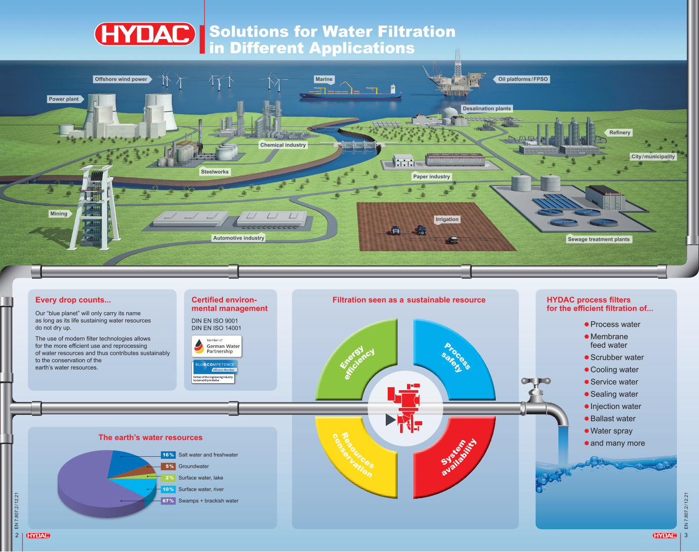
Solutions for Water Filtration in Different Applications
3
EN 7
.807
.2 / 1
2.21
Offshore wind power Oil platforms / FPSO
Refinery
City / municipality
Power plant
Mining
Chemical industry
Sewage treatment plants
Paper industry
Automotive industry
Steelworks
Irrigation
Desalination plants
Marine
2
EN 7
.807
.2 / 1
2.21
The earth’s water resources
Every drop counts...Our “blue planet” will only carry its name as long as its life sustaining water resources do not dry up.
The use of modern filter technologies allows for the more efficient use and reprocessing of water resources and thus contributes sustainably to the conservation of the earth’s water resources.
HYDAC process filters for the efficient filtration of...
lProcess water lMembrane
feed water lScrubber water lCooling water lService water lSealing water lInjection water lBallast water lWater spray land many more
Filtration seen as a sustainable resourceCertified environ- mental managementDIN EN ISO 9001DIN EN ISO 14001
Salt water and freshwater
Groundwater
Surface water, lake
Surface water, river
Swamps + brackish water67 %
16 %
5 %
2 %
10 %
conservation
availa
bilit
y
R
esources
Syste
m
En
ergy
Process
ef
f cien
cy
safety
5
EN 7
.807
.2 / 1
2.21
4
EN 7
.807
.2 / 1
2.21
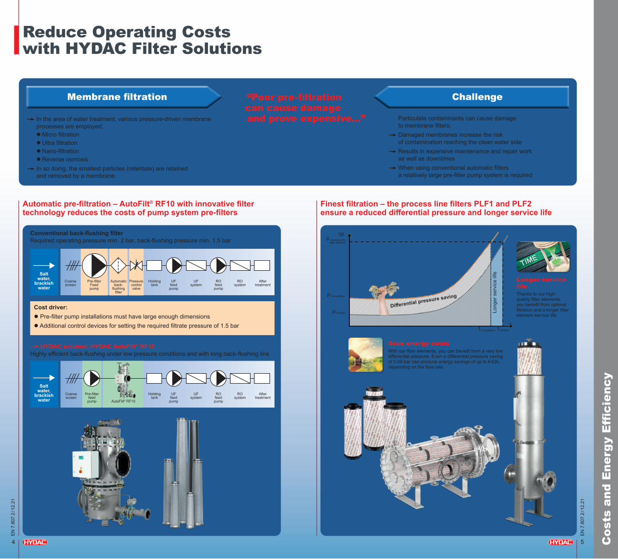
Reduce Operating Costs with HYDAC Filter Solutions
Finest filtration – the process line filters PLF1 and PLF2 ensure a reduced differential pressure and longer service life
Automatic pre-filtration – AutoFilt® RF10 with innovative filter technology reduces the costs of pump system pre-filters
Conventional back-flushing filterRequired operating pressure min. 2 bar, back-flushing pressure min. 1.5 bar
�HYDAC solution: HYDAC AutoFilt® RF10Highly efficient back-flushing under low pressure conditions and with long back-flushing line
Cost driver:l Pre-filter pump installations must have large enough dimensionsl Additional control devices for setting the required filtrate pressure of 1.5 bar
p Changing the filter element
∆p
p Competition
p HYDAC
t Competition t HYDAC
t
Long
er s
ervi
ce li
fe
Differential pressure saving
Longer service lifeThanks to our high- quality filter elements you benefit from optimal filtration and a longer filter element service life.
Save energy costsWith our filter elements, you can benefit from a very low differential pressure. Even a differential pressure saving of 0.49 bar can produce energy savings of up to €42k, depending on the flow rate.
Cos
ts a
nd E
nerg
y E
ffci
ency
Coarse screen
Coarse screen
Salt water,
brackish water
Salt water,
brackish water
Pre-filter Feed pump
Pre-filter feed
pump
Automatic back-
flushing filter
AutoFilt® RF10
Pressure control valve
Holding tank
Holding tank
UF feed
pump
UF feed
pump
UF system
UF system
RO system
RO system
After treatment
After treatment
RO feed pump
RO feed pump
�In the area of water treatment, various pressure-driven membrane processes are employed:
l Micro filtration l Ultra filtration l Nano-filtration l Reverse osmosis�In so doing, the smallest particles (retentate) are retained
and removed by a membrane.
Particulate contaminants can cause damage to membrane filters:
�Damaged membranes increase the risk of contamination reaching the clean water side
�Results in expensive maintenance and repair work as well as downtimes
�When using conventional automatic filters a relatively large pre-filter pump system is required
Membrane fltration Challenge “Poor pre-fltration can cause damage and prove expensive...”

Finest filtration 25 – 1 µm
The bodyguard for high requirements
PLF2 inline filter
Surface champion
Processmicron® and Flexmicron filter elements
Insurance against
downtimesPMRF
candle filters
Cleaning in place filtration
The bodyguard for high requirements
PLF1 inline filter
Fine filtration 200 – 25 µm
Allround talentAutoFilt®
RF3 / RF4 / RF5 / RF7
The specialist for low pressure
AutoFilt® RF10
Coarse filtration ≥ 200 µm
Dirt trapPRFS
screen basket filter
HybridAutoFilt® ATF
TwistFlow Strainer
6
EN 7
.807
.2 / 1
2.21
HYDAC Water Filtration – Work Areas and Fineness
7
EN 7
.807
.2 / 1
2.21
Ove
rvie
w
RO
RO
RO
MMF
UF
Intake
Intake
Challenges in water treatment...A reverse osmosis plant based on semi-permeable membranes is usually at the end of the water processing chain. The pre-filtered untreated water is pumped back through the membrane with a high pressure pump in order to separate it into pure water and waste water.
It becomes clear why the condition of the untreated water is of particular importance for the reverse osmosis (RO): contaminated or damaged membranes result in pressure losses and eventually in downtimes or damages to the entire system.
... and the solution from HYDAC Filter solutions from HYDAC can be used both as protective filters and work filters.
As protective filters they would be used for the pre-treatment of the media for the protection of ultra filtration systems (UF) or multi-media filters (MMF), and as work filters they can even take over the functions of ultra-filtration systems (UF) or multi-media filters (MMF) and perform the entire pre-treatment of the water prior to the reverse osmosis.
Intake = upstream
UF = ultra filtration
MMF = multi-media filters
RO = reverse osmosis
Intake
Filter element = Processmicron® High Flow / 9" HLC Con
vent
iona
l so
lutio
nC
onve
ntio
nal
solu
tion
Spec
ial
HYD
AC
sol
utio
n
Filter element = Processmicron® High Flow / 9" HLC
Filter element = Processmicron® High Flow 6"

8
EN 7
.807
.2 / 1
2.21
9
EN 7
.807
.2 / 1
2.21
The Hybrid: Automatic Filter AutoFilt® ATF TwistFlow Strainer
PRFS / PRFSD screen basket filter AutoFilt® TwistFlow Strainer ATF
Nominal size l DN 50 – DN 700
Volume flow Qmax l 3600 m3/h
Operating pressure pmax l 16 bar
Filtration ratings l 25 µm to 10000 µm
Nominal size l G 1" – DN 200
Volume flow Qmax l 400 m3/h, higher volume flows with skid solution possible
Operating pressure pmax l 16 bar
Filtration ratings l Dependent on particle nature and operating conditions
The Dirt Trapper: Process Screen Basket Filter PRFS / PRFSD
Product description l Screen basket filter –
also available as double filter
l Used as coarse filter, bypass filter or pre-separator
Screen basket technology l Screen basket insert with bracket
l Wire mesh 25 to 1000 µm
l Wedge wire: 50 to 3000 µm
l Perforated plate 3000 to 10000 µm
Product advantages l High filtration efficiency
l Simple handling
l Robust filter materials – ideal for long-term operation
l Cleanable filter materials
l Low operating costs
l Particles cannot enter the clean side when changing the basket
l Also available as a switchable double filter
Product description l Coarse separation by centrifugal force
with guaranteed filtration ratings
l 2-stage operating principle: 1. Centrifugal separation tackles � High contamination loads
2. Conical filter element � Guarantees the filtration rating
Filter element technology l Depending on the specific weight, even
particles < 100 µm are separated effectively
l Wedge wire or SuperMesh wire mesh 200 to 3000 µm
l Optional: SuperFlush non-stick coating
Product advantages l No transfer of contamination
to the clean side
l Suitable for a wide variability in the quality of untreated water
l Consistent filtrate quality
l Also available as skid solution for high flow rates
Sectional view PRFS Sectional drawing for AutoFilt® ATF Skid solution
Specifications Specifications
Coa
rse
Filt
rati
on ≥
200
µm

10
EN 7
.807
.2 / 1
2.21
11
EN 7
.807
.2 / 1
2.21
The Allrounder: Automatic Filters AutoFilt® RF3 / RF4 / RF5 / RF7
AutoFilt® RF3 / RF4 / RF5 / RF7
Nominal size l G 1" – DN 900
Volume flow Qmax l 7500 m3/h
Operating pressure pmax l 100 bar
Filtration ratings l 25 µm to 3000 µm
Product description l Self-cleaning automatic filter in – vertical design:
AutoFilt® RF3 / RF4 / RF5– horizontal design,
space-saving: AutoFilt® RF7 – compact design for low
volume flows: AutoFilt® RF4 – economy design with
vertical inlet, up to 200 µm: AutoFilt® RF5
Filter element technology l Conical filter elementsl Wedge wire: 50 to 3000 µm l SuperMesh wire mesh: 25 to 60 µm
Product advantages l Automatic back-flushing reduces
operating costsl Isokinetic filtration and back-flushing
provides greater efficiencyl Variable flange positionsl Numerous material and control variantsl No interruption of the filtrate flow
during back-flushingl Proved its worth over a thousand times
Back-flushing efficiency in conical filter elements compared to conventional cylinder filter elements
Specifications
The AutoFilt® TwistFlow Strainer ATF can achieve ratings finer than 200 µmDepending on the specific weight, even particles < 100 µm are separated effectively. Whereas with conventional hydrocyclones under changed operating conditions there is the risk of contamination reaching the clean side, the conical wedge wire in the AutoFilt® ATF performs a protective function (safety filter) with defined filtration ratings and thus prevents contamination reaching the clean side.
Efficiency / particle size
Specific weight 7.5 g/cm3
Specific weight 2.6 g/cm3
Specific weight 1.7 g/cm3
> 100 µm 99 % 98 % 77 %
100 – 75 µm 92 % 84 % 35 %
75 – 50 µm 87 % 78 % 21 %
Mode of operationFiltration
l Fluid enters the housing tangentially
l As a result of the tangential inflow and the conical housing cross-section, the fluid flows down in a spiral shape
l Particles with a high density are pressed against the housing wall by the centrifugal forces, and are deposited in the lower section of the housing
l Particles with a low density, which are not deposited below, are separated out by the conical slotted tube filter element with a defined filtration rating
Cleaning
l Deposited particles and those separated by the conical slotted tube filter element collect in the lower section and are removed periodically
l Cleaning is performed by flushing with unfiltered fluid
l Filtration is continuous as only partial flow is used for flushing
Low High
Sectional drawing for AutoFilt® RF3
Back- flushing line

12
EN 7
.807
.2 / 1
2.21
13
EN 7
.807
.2 / 1
2.21
The Specialist for Low Pressure – Automatic Filter AutoFilt® RF10
AutoFilt® RF10
Nominal size l DN 100 – DN 600
Volume flow Qmax l 3500 m3/h
Operating pressure pmax l 6 bar
Filtration ratings l 25 µm to 3000 µm
Product description l Self-cleaning automatic filter
l Hydrodynamic suction effect
l Conical JetFlush technology
Filter element technology l Conical filter elements
l Wedge wire: 50 to 3000 µm
l SuperMesh wire mesh: 25 to 60 µm
Product advantages l Back-flushing independent of pressure
on clean side of filter
l Dependent only on the inlet pressure
l Highly efficient back-flushing with low pressure conditions and long back-flush lines
l Suitable for high contamination loads and contamination peaks
Specifications
Versions
Mode of operation
Filtration Back-flushingFiltrationl The medium being filtered flows through the filter elements
from the inside to the outsidel Contamination particles then collect on the smooth inside
of the filter elementsl As the level of contamination increases, the differential
pressure between the contaminated and clean sides of the filter increases. If the pressure loss reaches the differential pressure trigger point, back-flushing starts automatically
Back-flushingl AutoFilt® RF3 / RF5 / RF7: The gear motor rotates the flushing
arm under the filter elements that need cleaningl AutoFilt® RF4: During automatic back-flushing, the pneumatic
drive rotates the filter element plate, including the filter elements, into the correct position, so that a contaminated filter element sits over the flushing opening
l The back-flush valve is openedl The pressure drop between filtrate side and back-flush
line flushes a small amount of the filtrate back through the contaminated filter elements
l The contaminant particles deposited on the inside of the filter elements are loosened and flushed into the back-flush line via the flushing arm
AutoFilt® RF3
The allrounder – proved its worth over a thousand times
AutoFilt® RF5
Economy with vertical inlet up to 200 µm
AutoFilt® RF4
Compact for low flow rates
AutoFilt® RF7
Horizontal design saves space
Filtration Back-flushing
Back-flushing efficiency in conical filter elements compared to conventional cylinder filter elements
Low High
Back-flushing independent of pressure on clean side of filter
Inlet �� Back-flushing line
Back- flushing line∆p

14
EN 7
.807
.2 / 1
2.21
15
EN 7
.807
.2 / 1
2.21
Fine
Filt
rati
on 2
00 –
25
µm
Filtration without interrupting production: Consistent performance and cleanliness
l The medium being filtered enters the filter housing via the filter inlet A and flows through the filter elements of the back-flushing filter from the inside to the outside B and leaves the filter via the filter outlet C
l During the filtration process, the JetFlush reservoir D located above the filter elements is filled with medium from the dirty side
l As fluid is filtered, particles collect on the inside of the filter elements
l As the level of contamination increases, the differential pressure between the contaminated and clean side of the filter increases
l When the differential pressure reaches the pre-set trigger point, back-flushing starts automatically
Triggering back-flushing
Automatic back-flushing is triggered:l In case of exceedance,
the differential pressure is triggeredl By means of a timerl By pressing the test button
Filtration functionFiltration
Filtration
Filtration
Back-flushing Phase 1
Back-flushingBack-flushing Phase 2
D
A
B B
C
Back-flushing function
A
E
F
I
H
G
J1
K
H
I
J2
Effective back-flushing without interrupting filtration
Phase 2 of back-flushing – Discharging the contamination:
l Once the core flow has developed, the JetFlush reservoir located above the filter element is closed J2
l Closing the filter element initiates the second phase, namely discharging the contamination: The fluid column which is already moving sucks water from the filtrate side to K because no fluid is entering the filter element because it is now closed at the top
l Due to the conical filter element geometry, the whole surface of the filter element is now clean and residue-free
l The contamination is discharged via the back-flushing line I
l After cleaning the filter element, the flushing arm rotates to the next filter element to be cleaned; the process is repeated
l When the back-flush cycle is finished, the back-flush valve is closed H
Simultaneously during filtration
Phase 1 of back-flushing – Removing the contamination particles
Back-flushing in general:l The gear motor E rotates the flushing arm F
to the filter element to be cleaned Gl The back-flush valve H opensl The pressure drop between the filter inlet A
and the back-flush line I, combined with the conical geometry of the element triggers the special jet-flush effect of the AutoFilt® RF10
l The remaining filter elements continue filtering to ensure uninterrupted filtration
Phase 1 of back-flushing – Stripping away the contamination:l In the first phase, unfiltered fluid from the JetFlush
reservoir J1 above flows into the filter elementl The conical filter element geometry produces a
core flow here, supplied mainly by the JetFlush reservoir
l This core flow is supported by the open JetFlush effect which also draws water from the filtrate side into the inside of the filter element
Back-flushing – Phase 2
Back-flushing – Phase 1
16
EN 7
.807
.2 / 1
2.21
17
EN 7
.807
.2 / 1
2.21
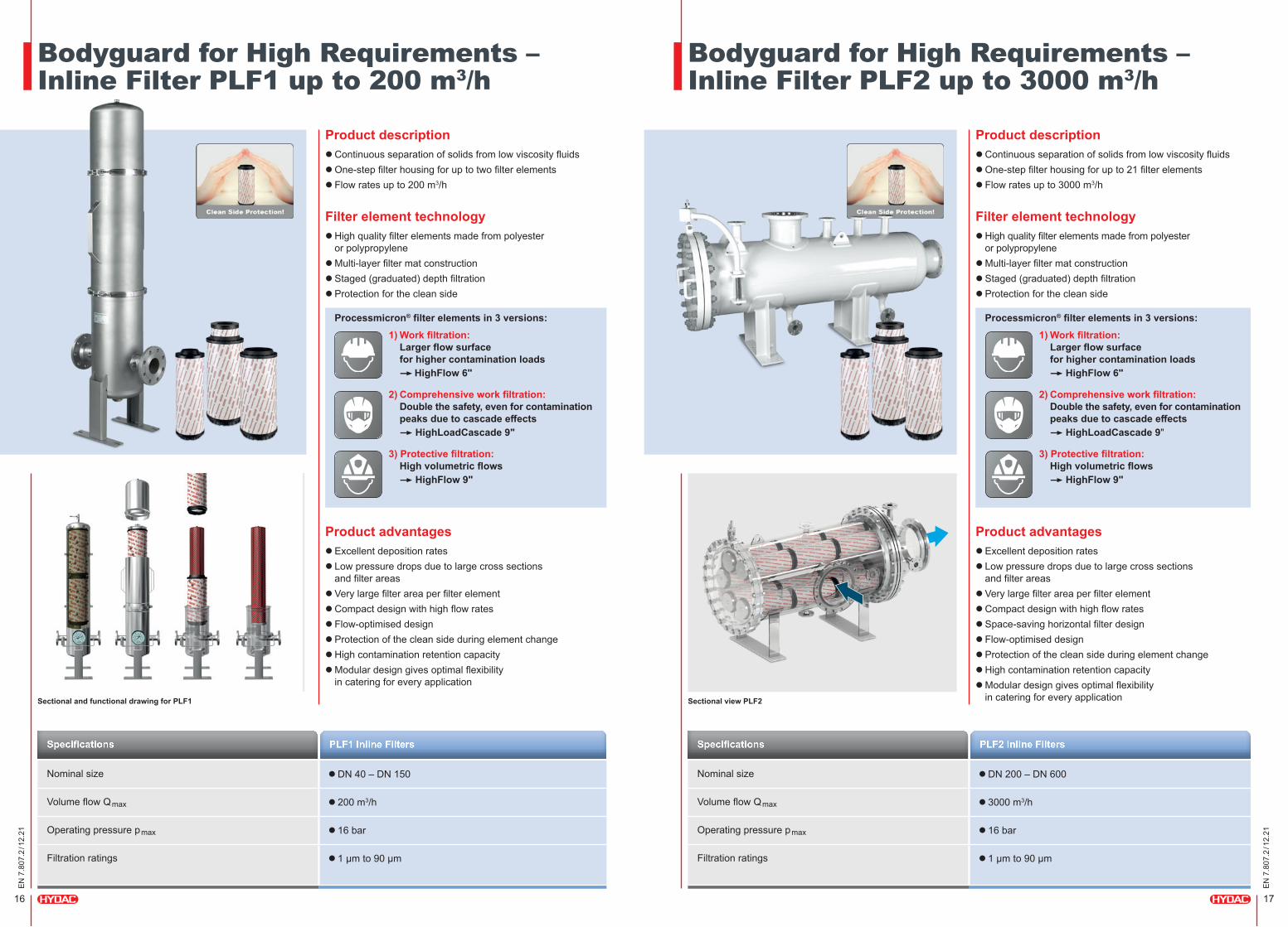
Bodyguard for High Requirements – Inline Filter PLF1 up to 200 m3/h
Bodyguard for High Requirements – Inline Filter PLF2 up to 3000 m3/h
PLF2 Inline FiltersPLF1 Inline Filters
Nominal size l DN 200 – DN 600
Volume flow Qmax l 3000 m3/h
Operating pressure pmax l 16 bar
Filtration ratings l 1 µm to 90 µm
Nominal size l DN 40 – DN 150
Volume flow Qmax l 200 m3/h
Operating pressure pmax l 16 bar
Filtration ratings l 1 µm to 90 µm
Product description l Continuous separation of solids from low viscosity fluidsl One-step filter housing for up to two filter elementsl Flow rates up to 200 m3/h
Filter element technology l High quality filter elements made from polyester
or polypropylenel Multi-layer filter mat constructionl Staged (graduated) depth filtrationl Protection for the clean side
Product description l Continuous separation of solids from low viscosity fluidsl One-step filter housing for up to 21 filter elementsl Flow rates up to 3000 m3/h
Filter element technology l High quality filter elements made from polyester
or polypropylenel Multi-layer filter mat constructionl Staged (graduated) depth filtrationl Protection for the clean side
Product advantages l Excellent deposition ratesl Low pressure drops due to large cross sections
and filter areasl Very large filter area per filter elementl Compact design with high flow ratesl Flow-optimised designl Protection of the clean side during element changel High contamination retention capacityl Modular design gives optimal flexibility
in catering for every application
Product advantages l Excellent deposition ratesl Low pressure drops due to large cross sections
and filter areasl Very large filter area per filter elementl Compact design with high flow ratesl Space-saving horizontal filter designl Flow-optimised designl Protection of the clean side during element changel High contamination retention capacityl Modular design gives optimal flexibility
in catering for every application
Processmicron® filter elements in 3 versions: Processmicron® filter elements in 3 versions:1) Work filtration: Larger flow surface
for higher contamination loads � HighFlow 6"
2) Comprehensive work filtration: Double the safety, even for contamination
peaks due to cascade effects �HighLoadCascade 9"
3) Protective filtration: High volumetric flows �HighFlow 9"
1) Work filtration: Larger flow surface
for higher contamination loads �HighFlow 6"
2) Comprehensive work filtration: Double the safety, even for contamination
peaks due to cascade effects �HighLoadCascade 9"
3) Protective filtration: High volumetric flows �HighFlow 9"
Sectional view PLF2Sectional and functional drawing for PLF1
SpecificationsSpecifications

18
EN 7
.807
.2 / 1
2.21
19
EN 7
.807
.2 / 1
2.21
Ver
y Fi
ne F
iltra
tion
25
– 1
µm
Processmicron® Filter Elements for Series PLF1 and PLF2
Insurance against Downtimes – Candle Filters PMRF
PMRF Candle Filters
Nominal size l G 1" – DN 250
Volume flow Qmax l 1200 m3/h
Operating pressure pmax l 40 bar
Filtration ratings l 1 µm to 90 µm
Product description l Separation of solid particles from low viscosity fluids
l Suitable for applications with the highest cleanliness requirements
l Tried-and-tested candle filter technology for finest filtration
l Also available as a switchable double filter
Filter element technology l Filtration ratings: 1 µm to 90 µm
l Flexmicron Premium: durable, pleated filter elements (pleat technology) with low layer thickness made from melt-blown or high-quality glass fibres for graduated depth filtration
�Long service life even in fluids difficult to filter
l Flexmicron Standard: Spun Spray depth filter elements (melt-blown) for graduated depth filtration: high cleanliness in a single pass, high filter thickness of filter medium
�High storage volume for contamination
l Flexmicron Economy: Spun Spray depth filter elements (melt-blown) suitable for applications with medium requirements for fluid and type purity
�Inexpensive solution
Product advantages l Economic operation through high quality standards,
defined filtration rates and high separation values
l Compact housing with high flow rates
l Service-friendly for filter element change
l Efficient system and component protection
l Environmentally safe disposal, as incinerable
Technical data l Filtration ratings: 1 µm to 90 µm l Length: 20", outer diameter 6" or 9" l Type of filter element pleated or Spun Sprayl Filter material: polyester or polypropylene
The right filter element for optimal particle filtration
Design of Processmicron® Filter Elements
Sectional view PMRF
Specifications
HighFlow 6"Working filtration: l M-pleatl Optimised, enlarged upstream area
for high polluting loads
Multi-layer filter mat constructionl Robust and high-quality layer structure � No skewing of the filter layers
l High contamination retentionl Low pressure loss
Staged (graduated) depth filtrationl High purity in single passagel High layer thickness of the filter medium� High storage volume for contamination
HighLoadCascade 9"Comprehensive working filtration:l Combination of parallel folds (outside)
and M-folds (inside)l Double security, even with contamination surges,
thanks to cascading effectl Selection of filter layers precisely tailored to the
filtration task at hand (outer and inner layers)
HighFlow 9"Protective filtration: l Pleated filter element construction (parallel folding)l High flow ratesl Extreme fold stability through parallel folding
at large filter element circumference
Contam
inatio
n

EN 7
.807
.2 / 1
2.21
Coo
ling
Syst
ems
57.0
00El
ectro
nics
180
.000
Acce
ssor
ies
61.0
00C
ompa
ct H
ydra
ulic
s 53
.000
Filte
r Sys
tem
s 79
.000
Proc
ess
Tech
nolo
gy 7
7.00
0Fi
lter T
echn
olog
y 70
.000
Accu
mul
ator
Tec
hnol
ogy
30.0
00
Global Presence. Local Expertise. www.hydac.com
Head Office Industriegebiet Grube König HYDAC Process Technology Am Wrangelflöz 1 GmbH 66538 Neunkirchen Germany
Tel.: +49 6897 509-1241 Fax: +49 6897 509-1278
E-mail: [email protected] Internet: www.hydac.com
HYDAC HeadquartersHYDAC CompaniesHYDAC Sales and Service Partners Free Sales Partners


