32
January, 1990 Eaton ® Hydrostatic Variable Motors Series 1 Models 33-64 Hydrostatic Variable Motors Repair Information

January, 1990Eaton®
Hydrostatic Variable Motors
Series 1 Models 33-64Hydrostatic Variable Motors
Repair Information

2
Table of Contentspage
ID Tag ........................................................................................................................................................... 3
Required Tools .............................................................................................................................................. 3
Introduction and Part Names ........................................................................................................................ 4
Exploded View Drawing ................................................................................................................................ 5
Minor Repairs: ............................................................................................................................................. 6
Control Valve Inspection ......................................................................................................................... 6
Orifice Installation ................................................................................................................................... 7
Shaft Seal Replacement ......................................................................................................................... 8
Valve Block Inspection ........................................................................................................................... 9
Major Repairs: Disassembly ................................................................................................................... 11
Shaft Seal and Control Valve ............................................................................................................... 11
Valve Block ........................................................................................................................................... 12
End Cover and Servo Pistons .............................................................................................................. 14
Mounting Flange, Servo Pistons and Trunnions ................................................................................... 16
Swashplate, Shaft and Cylinder Block .................................................................................................. 18
Major Repairs: Reassembly .................................................................................................................... 19
Slipper Clearance ................................................................................................................................. 19
Trunnions and Servo Pistons ............................................................................................................... 20
Minimum Displacement Setting ............................................................................................................ 21
Mounting Flange, End Cover Bearing and Shaft End Play ................................................................... 24
End Cover, Valve Block and Control Valve .......................................................................................... 26
Shaft Seal ............................................................................................................................................. 28
Special Tools............................................................................................................................................... 28
Hydraulic Fluid Recommendations ............................................................................................................. 30

3
Eaton CorporationHydraulics DivisionSpencer, Iowa 51301
Rotation
Serial No.
Model No.
Eaton0000 00 - 00000 00 000000
• 9/64 in. Hex Key • Small Screwdriver (1/8 in. Blade)
• 1/4 in. Hex Key • Hammer ( steel and Plastic)
• 1/2 in. Socket • Depth Micrometer
• 9/16 in. Socket • Slide Hammer
• 5/8 in. Socket • Split Blade Bearing Puller
• 3/4 in. Socket • Prick Punch
• 7/8 in. Socket • Scribe
• 1 in. Socket • Punch
• 1-3/8 in. Socket • Arbor Press
• Dial Indicator with Magnetic Base • Clean, Lint Free Cloths
• Spring Compression Scale (0-10 lbs) • Loctite
• No. 5 or 7 Retaining Ring Pliers • Light Petroleum Jelly
• Adjustable joint Pliers • Suitable Solvents and Cleaners
• 3 in.X 1/4-20 Bolt • Rotating Seal Puller (Special)
• Breaker Bar or Ratchet Wrench • Low Clearance Bearing Puller (Special)
• Torque Wrench (200 lb-ft capacity) • Bearing Cone Driver (Special)
• 18 to 20 in. Adjustable Wrench
Required Tools
Special Tools are shown on pages 28 and 29.
ID Tag
A - Displacement (cu.in./rev.)0033 = 3.30039 = 3.90046 = 4.60054 = 5.40064 = 6.40076 = 7.6
B - Identifies Type of Product21 = Variable Displacement Pump31 = Fixed Displacement Motor41 = Variable Displacement Motor
C - Identifies Specific Unit Configuration
D - Month of Manufactur
E - Year of Manufacture
F - Specific Serial Number of Unit
G - Identifies Direction of Input Shaft (Pumps Only) RotationObserved from Shaft End of UnitCW = ClockwiseCCW = Counterclockwise
E F
A CB
G
D

4
Introduction and Part Names
Introduction
This manual provides service information for Eaton Models 33 thru 64 Variable Motors. It’s divided into two mainsections: the first covers minor repairs and the second gives instructions for the complete disassembly, inspectionand reassembly of the motor.
The following recommendations apply to both minor and major repairs:
• Most repairs require the removal of the motor from the vehicle.
• Cleanliness is extremely important.
• Clean the port areas thoroughly before disconnecting the hydraulic lines.
• Plug the motor ports and cover the open end of the hydraulic line immediately after they’re disconnected.
• Drain the oil and clean the exterior of the motor before making repairs.
• Wash all metal parts in clean solvent.
• Use compressed air to dry the parts. Do not wipe them dry with paper towels or cloth; Lint in a hydraulic systemwill cause damage.
• The compressed air should be filtered and moisture free.
• Always use new seals when reassembling hydraulic motors.
• For replacement parts and ordering information refer to parts list 6-132.
• Lubricate the new seals with a petroleum jelly like Vaseline before installation.
• Torque all bolts over gasketed joints, then repeat the torquing sequence to make-up for gasket compression.
• Verifying the accuracy of motor repairs on an authorized test stand is essential.
♦ Parts used as required.
Models 33 thru 64 Variable Motor Parts
ItemNo. Description Qty.
ItemNo. Description Qty.
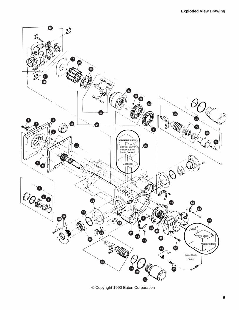
1 Shaft Seal Kit 1 32 Trunnion Shims ♦2 O-ring 1 34 Plug and O-ring 13 O-ring 1 35 Motor Housing 14 Mounting Flange Bolt 12 36 Servo Piston S/A 25 Shipping Strap 2 37 Retaining Ring 46 Mounting Flange S/A 1 38 Pin 27 Bearing Cup 1 39 O-ring 28 Dowel Pin 7 40 O-ring 29 Mounting Flange Gasket 1 41 Servo Sleeve 2
10 Drive Shaft S/A 1 42 Servo Sleeve Retainer 211 Replacement Bearing Kit ♦ 43 Cap Screw 612 Swashplate S/A 1 44 End Cover Gasket 113 Thrust Plate 1 45 Replacement Bearing Kit ♦14 Rotating Group 1 46 Shaft Shims ♦15 Piston and Slipper S/A 9 47 End Cover 116 Slipper Retainer Plate 1 52 End Cover Bolt 619 Retaining Strap and Bolts 2 53 End Cover Bolt 220 Cylinder Barrel 1 54 Valve Block Option 121 Bearing Plate 1 63 Hose Fitting ♦22 Valve Plate 1 65 Hose ♦23 Control Valve Option 1 71 Servo Piston with Spacer 128 Trunnion Bolt 6 72 Spacer Shims ♦29 Trunnion S/A 2 73 Servo Piston Spacer 130 Replacement Bearing Kit ♦ 74 Spacer Bolt 131 O-ring 2
5
Exploded View Drawing
© Copyright 1990 Eaton Corporation
Seals
Valve Block
5363
47
4546
43
4235
34
36
3940
41
65
854
51
52
44
73
74
36
71
72
20
21
22
8
16
19
13 15
37
38
12
4
5
6
7
8 9
11
10
14
23
8
Mounting Bolts
Gasket(s)
Control Valve/Port Plate forSlave Control
1
2 3
28 29
31
32
33
30
Mounting Bolts
Valve Block
Seals
6
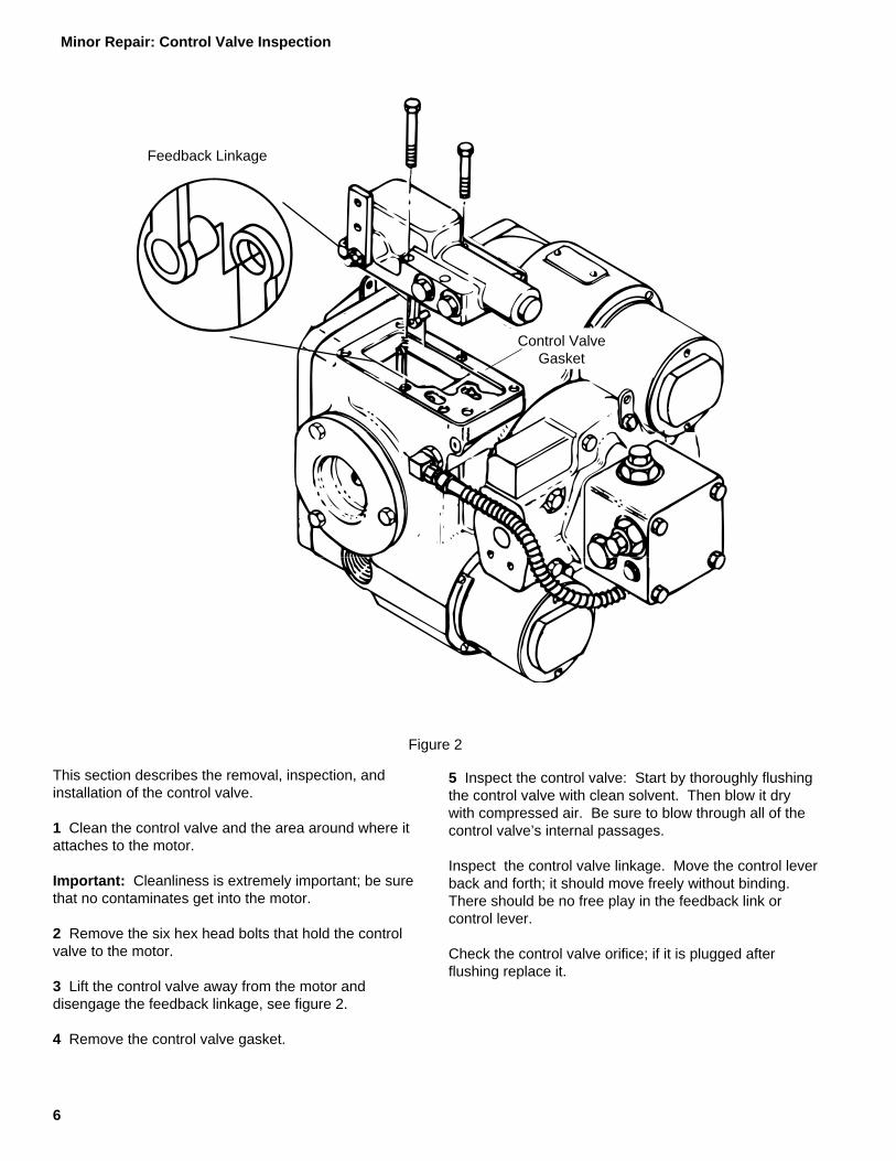
This section describes the removal, inspection, andinstallation of the control valve.
1 Clean the control valve and the area around where itattaches to the motor.
Important: Cleanliness is extremely important; be surethat no contaminates get into the motor.
2 Remove the six hex head bolts that hold the controlvalve to the motor.
3 Lift the control valve away from the motor anddisengage the feedback linkage, see figure 2.
4 Remove the control valve gasket.
5 Inspect the control valve: Start by thoroughly flushingthe control valve with clean solvent. Then blow it drywith compressed air. Be sure to blow through all of thecontrol valve’s internal passages.
Inspect the control valve linkage. Move the control leverback and forth; it should move freely without binding.There should be no free play in the feedback link orcontrol lever.
Check the control valve orifice; if it is plugged afterflushing replace it.
Figure 2
Feedback Linkage
Control ValveGasket
Minor Repair: Control Valve Inspection

7
Note: There are two types of control valve orifices:
Shallow Orifice Pocket
.058 in.
Stake in 3 Places
Control Valve
Deep Orifice Pocket
.180 in.Control Valve
6 Place a new control valve gasket on the motor.
7 Connect the feedback linkage and position the controlvalve on the motor.
Important: When the control valve is positioned on themotor make sure the feedback linkage points towardsthe motor’s end cover.
8 Install the six hex head bolts and tighten them fingertight.
9 Move the control lever back and forth; it should movefreely in both directions and self-center. If it doesn’trecheck the feedback linkage.
10 Tighten the six hex head bolts to 16 lb-ft [22 Nm].
The plate orifice is used in control valves that have ashallow orifice pockets.
The orifice size is stamped on the orifice in thousandthsof an inch, example: 57 = .057 in.
Install the plate orifice so the orifice size is visible. Stakeit in three places with a center punch. Insure that theorifice is properly seated after staking.
The plug is used in control valves that have a deeporifice pockets.
Before installing the plug orifice be sure that the o-ring isin place. Apply petroleum jelly to the edge of the plugorifice and o-ring.
Carefully insert the plug orifice into the orifice pocket;The large opening in the plug must go into the controlvalve.
This section describes the removal, inspection, and installation of the control valve.
1 Clean the control valve and the area around where it attaches to the motor.
Important: Cleanliness is extremely important; be sure that no contamination gets into the motor.
2 Remove the six hex head bolts that hold the control valve to the motor.
3 Lift the control valve away from the motor and disengage the feedback linkage, see figure 2.
4 Remove the control valve gasket.
5 Inspect the control valve: Start by thoroughly flushing the control valve with clean solvent. Then blow it dry withcompressed air. Be sure to blow through all of the control valve’s internal passages.
Inspect the control valve linkage. Move the control lever back and forth; it should move freely without binding. Thereshould be no free play in the feedback link or control lever.
Check the control valve orifice; if it is plugged after flushing replace it.
6 Place a new control valve gasket on the motor.
Minor Repair: Control Valve Inspection

8
This section describes the removal and installation of themotor’s shaft seal.
1 Drain the oil from the motor.
2 Position the motor so the shaft seal is accessible.
3 Clean the area around the motor shaft and seal.
Important: Cleanliness is extremely important; be surethat no contaminates get into the motor.
4 Using a retaining ring pliers remove the retaining ring.
5 Screw a 3 in. X 1/4-20 bolt into the threaded hole inthe stationary seal. Pull on the bolt to remove the seal.
6 Use the special pulling tool, Owatonna Tool Co. P/NCAS 1844, to remove the rotating seal, see figure 1. Ifthe special tool is not available pull out the rotating sealwith a wire bent to the shape of the puller.
Note: Detailed drawings of all special tools are given inthe back of this manual.
7 Remove the o-ring; it will either be in the rotating sealor on the shaft.
Note: Eaton recommends replacing the entire shaftseal. Use Shaft Seal Kit P/N 990231.
Important: The metal-to-metal sealing surfaces arecritical. Clean the areas of contact with a suitablesolvent then blow them dry. The solvent must evaporatewithout leaving a residue. Do not touch the sealingsurfaces after cleaning.
8 Apply petroleum jelly to the o-ring and install it in therotating seal
9 Apply a light coating of clean hydraulic oil to thecleaned metal sealing surface of the rotating seal.
10 Install the rotating seal using the special pulling tool(CAS 1844).
11 Screw a 3 in. X 1/4-20 bolt into the threaded hole inthe new stationary seal. The bolt provides a convenientmeans for holding the seal.
12 Apply petroleum jelly to the o-ring that is around thelargest part of the stationary seal.
13 Apply a light coating of clean hydraulic oil to thecleaned metal sealing surface of the stationary seal.
14 Install the stationary seal.
15 Using the retaining ring pliers install the retaining ringwith the beveled side out.
Figure 1
Bolt
Rotating Seal
O-ring
Stationary Seal
Pulling Tool
Minor Repair: Seal Shaft Inspection

9
This section describes the removal, inspection, andinstallation of the valve block.
1 Clean the valve block and the area around where itattaches to the motor.
Important: Cleanliness is extremely important; be surethat no contaminates get into the motor.
2 Position the motor so the valve block is accessible.
7 Remove the two o-rings and back-up rings, and thesquare cut seal from between the valve block and motor,see figure 3.
8 Remove the low pressure relief valve (also called thecharge pressure relief valve).
Note: The low pressure relief valve can be identified bythe notches machined into its large hex head, see figure4.
9 Mark the high pressure relief valves so they can bereinstalled in the same ports.
Note: The three digit number stamped on each reliefvalve indicates its pressure setting. Multiply this numberby ten to get the actual pressure setting (in PSI).Examples:
11 Remove the o-rings and back-up rings from the reliefvalves. The small o-ring on each high pressure reliefhas a back-up ring on each side. The small o-ring onthe low pressure relief valve doesn’t have back-up rings.
12 Inspect the relief valves for damage and replace asnecessary.
Figure 4
Back-upRings
Notches
Low PressureRelief
High PressureRelief
O-ring
10 Remove the high pressure relief valves.
NumberStamped onRelief Valve
MultiplierRelief Valve
PressureSetting
500 x10 5000 PSI
016 x10 160 PSI
Figure 3
Sq. Cut Seal
ControlPressure
Hose
Bolt (4)
Hose FittingValve Block
Back-up Ring
O-ring
3 If the motor gets control pressure from the valve blockdisconnect the hose at the valve block and remove thehose fitting.
4 Loosen the plugs and relief valves that are screwedinto the valve block.
5 Remove the four hex head bolts that hold the valveblock to the motor.
6 Remove the valve block.
O-ring
Minor Repair: Valve Block Inspection

10
Low PressureRelief Valve
High PressureRelief Valve
Gauge PortPlugs
ValveBlock
13 Remove the gauge port plugs and o-rings.
Figure 5
Figure 6
Spool
Shuttle ValvePlug
Valve Block
Shuttle ValveSpring
Shuttle Valves
14 Remove the shuttle valve plugs and o-rings.
15 Remove the shuttle valve springs, spool, and valves.
16 Wash the relief valves, plugs, and shuttle valve inclean solvent. Flush out the valve block. Blow dry theparts with compressed air. Be sure to blow through theinternal passages of the valve block. Inspect the partsfor damage and replace as necessary.
17 Install the relief valves, shuttle valve, and plugs. Usenew o-rings and back-up rings.
Install back-up rings around the small o-rings on the highpressure relief valves, see figure 4.
Lubricate the new o-rings with petroleum jelly beforeinstallation.
Tighten all plugs and relief valves finger tight. They willbe torqued after the valve block is mounted on themotor.
Back-up Ring
O-ring
Sq. Cut Seal
Hose Fitting
Figure 7
Bolt (4)
Valve Block
18 Install new o-rings and back-up rings in the groovesaround the high pressure ports as shown in figure 7.Install a square-cut seal in the groove around the lowpressure port. Use petroleum jelly to hold these sealingrings in place while the valve block is installed.
19 Position the valve block on the motor. Install the fourhex head bolts and tighten them to 28 lb-ft [38 Nm].
20 Tighten the high pressure relief valves to 25 lb-ft [34Nm].
Tighten the low pressure relief valve, and shuttle valveplugs to 80 lb-ft [108 Nm].
Tighten the gauge port plugs and control pressure fitting,if used, to 17 lb-ft [23 Nm].
21 Connect the control pressure hose to the valve blockfitting, if used.
Note: The control pressure hose is now obsolete. Poormotor control characteristics may be experienced whenthe motor gets control pressure from the valve block. Itis best to run a separate control pressure line from thecharge pump to the motor. If possible re-plumb theapplication so the control pressure hose is no longerused. Be sure to plug the port in the valve block.
Minor Repair: Valve Block Inspection

11
Disassembly
This section describes the complete disassembly,inspection,and reassembly of the motor. Due to thecomplexity of the heavy duty motor certainsubassemblies are disassembled, inspected, andreassembled upon removal from the motor. Thisprocedure insures repair accuracy and helps avoid theloss of small parts.
When major repairs are planned it is recommended thatthe process laid out in this section be followed from startto finish.
1 Clean the exterior of the motor and drain the oil.
2 Position the motor so the shaft seal is accessible.
Important: Cleanliness is extremely important; be surethat no contaminates get into the motor.
Figure 8
Pulling Tool
O-ring
Rotating Seal
Stationary Seal
Bolt
3 Using a retaining ring pliers remove the retaining ring.
4 Screw a 3 in. X 1/4-20 bolt into the threaded hole inthe stationary seal. Pull on the bolt to remove the seal.
5 Use the special pulling tool, Owatonna Tool Co. P/NCAS 1844, to remove the rotating seal, see figure 8. Ifthe special tool is not available pull out the rotating sealwith a wire bent to the shape of the puller.
Note: Detailed drawings of all special tools are given inthe back of this manual.
6 Remove the o-ring; it will either be in the rotating sealor on the shaft.
7 Remove the six hex head bolts that hold the controlvalve to the motor.
8 Lift the control valve away from the motor anddisengage the feedback linkage, see figure 9.
9 Remove the control valve gasket.
10 Inspect the control valve: Start by thoroughlyflushing the control valve with clean solvent. Then blowit dry with compressed air. Be sure to blow through all ofthe control valve’s internal passages.
Inspect the control valve linkage. Move the control leverback and forth; it should move freely without binding.There should be no free play in the feedback link orcontrol lever.
Check the control valve orifice; if it is plugged afterflushing replace it.
FeedbackLinkage
Control ValveGasket
Figure 9
Major Repairs: Shaft Seal and Control Valve

12
11 Reposition the motor so the shaft is vertical and thevalve block is on top. Stand the motor on two blocks ofwood as shown in figure 10.
12 If the motor gets control pressure from the valveblock remove the control pressure hose and fittings.
13 Loosen the plugs and relief valves that are screwedinto the valve block.
14 Remove the four hex head bolts that hold the valveblock to the motor.
15 Remove the valve block.
16 Remove the two o-rings and back-up rings, and thesquare cut seal from between the valve block and motor,see figure 10.
17 Remove the low pressure relief valve (also called thecharge pressure relief valve).
Note: The low pressure relief valve can be identified bythe notches machined into its large hex head, see figure11.
18 Mark the high pressure relief valves so they can bereinstalled in the same ports.
Note: The three digit number stamped on each reliefvalve indicates its pressure setting. Multiply this numberby ten to get the actual pressure setting (in PSI).Examples:
20 Remove the o-rings and back-up rings from the reliefvalves. The small o-ring on each high pressure reliefvalve has a back-up ring on each side. The small o-ringon the low pressure relief valve doesn’t have back-uprings.
21 Inspect the relief valves for damage and replace asnecessary.
O-ring
High PressureRelief
Low PressureRelief
O-ring
Back-upRings
Notches
Figure 11
19 Remove the high pressure relief valves.
NumberStamped onRelief Valve
MultiplierRelief Valve
PressureSetting
500 x10 5000 PSI
016 x10 160 PSI
ControlPressure
Hose
Hose FittingBolt (4)
Valve Block
Sq. Cut Seal
Back-up RingO-ring
Figure 10
Major Repairs: Valve Block

13
Shuttle ValveSpring
Spool
Shuttle Valves
Shuttle ValvePlug
Valve Block
Figure 13
ValveBlock
Gauge PortPlugs
Low PressureRelief Valve
High PressureRelief Valve
Figure 12
22 Remove the gauge port plugs and o-rings.
23 Remove the shuttle valve plugs and o-rings.
24 Remove the shuttle valve springs, spool, and valves.
25 Wash the relief valves, plugs, and shuttle valve inclean solvent. Flush out the valve block. Blow dry theparts with compressed air. Be sure to blow through theinternal passages of the valve block. Inspect the partsfor damage and replace as necessary.
26 Install the relief valves, shuttle valve, and plugs. Usenew o-rings and back-up rings.
Install back-up rings around the small o-rings on the highpressure relief valves, see figure 11.
Lubricate the new o-rings with petroleum jelly beforeinstallation.
Tighten all plugs and relief valves finger tight. They willbe torqued after the valve block is mounted on themotor.
Major Repairs: Valve Block
14
Valve Plate
Bearing Plate
Dowel Pin (7)
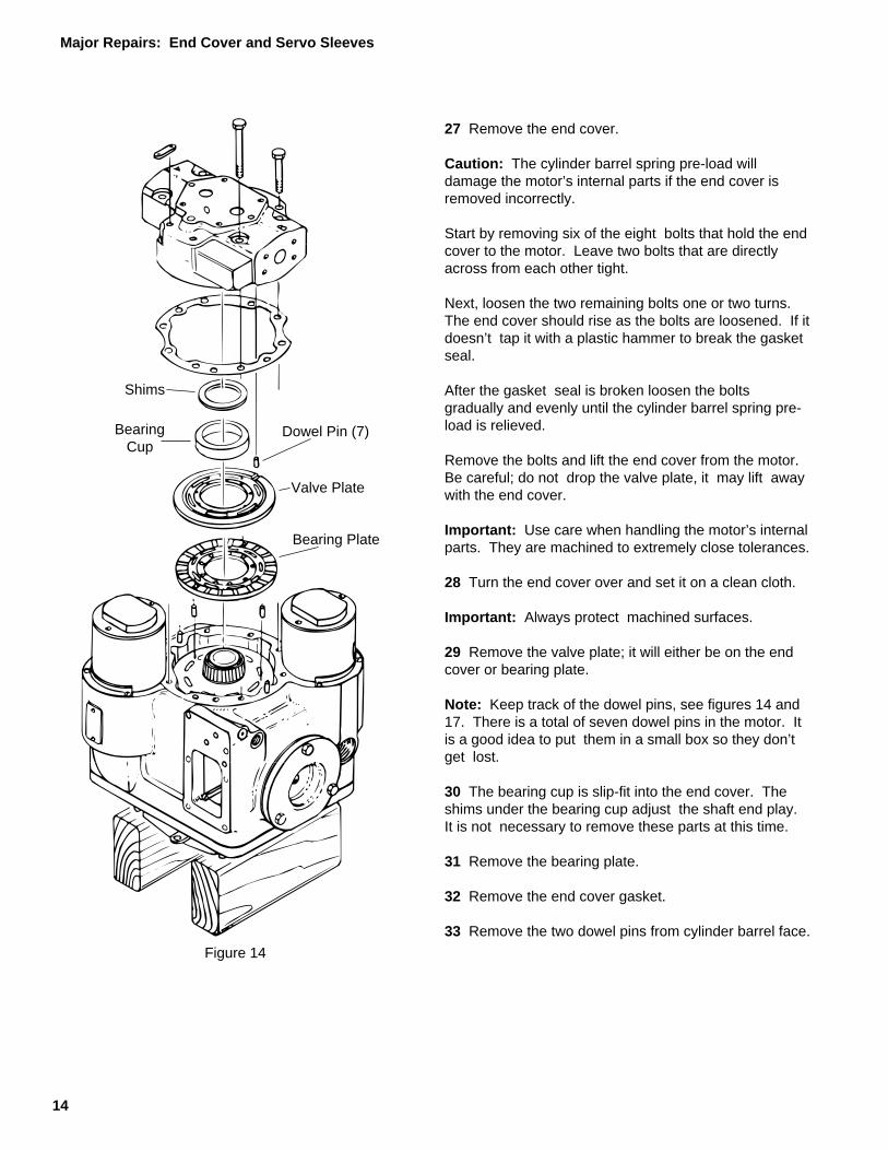
Figure 14
27 Remove the end cover.
Caution: The cylinder barrel spring pre-load willdamage the motor’s internal parts if the end cover isremoved incorrectly.
Start by removing six of the eight bolts that hold the endcover to the motor. Leave two bolts that are directlyacross from each other tight.
Next, loosen the two remaining bolts one or two turns.The end cover should rise as the bolts are loosened. If itdoesn’t tap it with a plastic hammer to break the gasketseal.
After the gasket seal is broken loosen the boltsgradually and evenly until the cylinder barrel spring pre-load is relieved.
Remove the bolts and lift the end cover from the motor.Be careful; do not drop the valve plate, it may lift awaywith the end cover.
Important: Use care when handling the motor’s internalparts. They are machined to extremely close tolerances.
28 Turn the end cover over and set it on a clean cloth.
Important: Always protect machined surfaces.
29 Remove the valve plate; it will either be on the endcover or bearing plate.
Note: Keep track of the dowel pins, see figures 14 and17. There is a total of seven dowel pins in the motor. Itis a good idea to put them in a small box so they don’tget lost.
30 The bearing cup is slip-fit into the end cover. Theshims under the bearing cup adjust the shaft end play.It is not necessary to remove these parts at this time.
31 Remove the bearing plate.
32 Remove the end cover gasket.
33 Remove the two dowel pins from cylinder barrel face.
Shims
BearingCup
Major Repairs: End Cover and Servo Sleeves
15
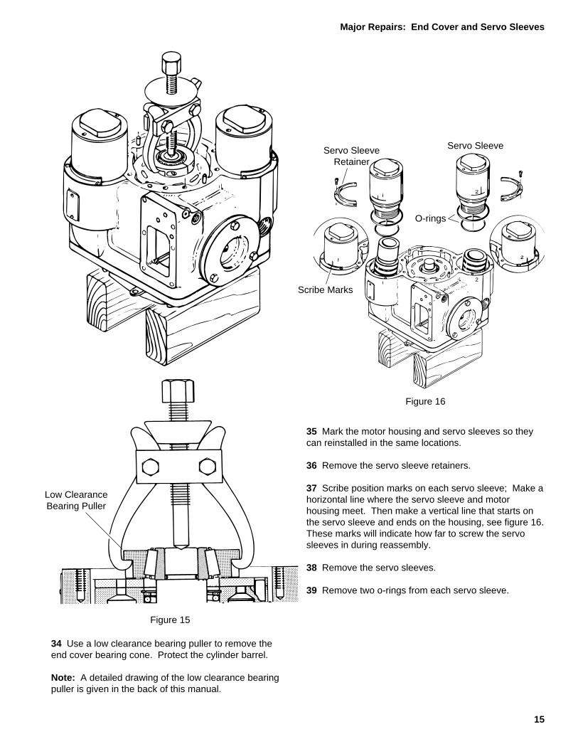
34 Use a low clearance bearing puller to remove theend cover bearing cone. Protect the cylinder barrel.
Note: A detailed drawing of the low clearance bearingpuller is given in the back of this manual.
Figure 15
Low ClearanceBearing Puller
Scribe Marks2
Servo Sleeve
O-rings
Servo SleeveRetainer
Figure 16
35 Mark the motor housing and servo sleeves so theycan reinstalled in the same locations.
36 Remove the servo sleeve retainers.
37 Scribe position marks on each servo sleeve; Make ahorizontal line where the servo sleeve and motorhousing meet. Then make a vertical line that starts onthe servo sleeve and ends on the housing, see figure 16.These marks will indicate how far to screw the servosleeves in during reassembly.
38 Remove the servo sleeves.
39 Remove two o-rings from each servo sleeve.
Major Repairs: End Cover and Servo Sleeves

16
Bolt (12)Mounting Flange
Bearing Cup
DowelPin
Gasket
Figure 17
40 Reposition the motor so the control valve mount ison top. Be careful; do not let the cylinder barrel slideout of the motor.
41 Remove the twelve hex head bolts that hold themounting flange to the motor.
42 Remove the mounting flange, tapping it with aplastic hammer will help to break it loose.
43 Remove the mounting flange gasket.
Note: Do not remove the bearing cup from the mountingflange unless it is damaged. Go to step 46 if the bearingcup is undamaged.
44 Use an internal bearing puller or a long punch toremove the old bearing cup. Be careful; do not damagethe mounting flange.
45 Press the new bearing cup into the mounting flange.Be sure that it is pressed all the way to the bottom of therecess.
Case DrainHole
Servo Pistons
Pin
Retaining Rings
Figure 18
46 Remove the inside retaining ring from each of thepins that connect the servo piston links to theswashplate. Slide the pins out through the case drainholes and remove the servo pistons, see figure 18.
Note: Disassembly of the servo pistons is not requiredunless they are damaged or the motor’s minimumdisplacement is being changed.
Major Repairs: Mounting Flange, Servo Pistons and Trunnions
17
Sliding HammerPuller
Mark Trunnionand Housing
Shims
O-ring
O-ringShims
Trunnion BearingCone
Figure 19
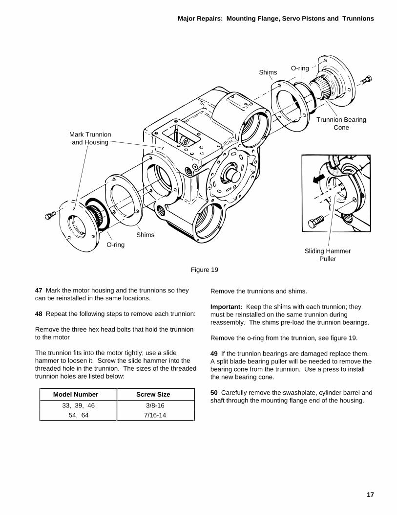
47 Mark the motor housing and the trunnions so theycan be reinstalled in the same locations.
48 Repeat the following steps to remove each trunnion:
Remove the three hex head bolts that hold the trunnionto the motor
The trunnion fits into the motor tightly; use a slidehammer to loosen it. Screw the slide hammer into thethreaded hole in the trunnion. The sizes of the threadedtrunnion holes are listed below:
Remove the trunnions and shims.
Important: Keep the shims with each trunnion; theymust be reinstalled on the same trunnion duringreassembly. The shims pre-load the trunnion bearings.
Remove the o-ring from the trunnion, see figure 19.
49 If the trunnion bearings are damaged replace them.A split blade bearing puller will be needed to remove thebearing cone from the trunnion. Use a press to installthe new bearing cone.
50 Carefully remove the swashplate, cylinder barrel andshaft through the mounting flange end of the housing.
Model Number Screw Size
33, 39, 46 3/8-16
54, 64 7/16-14
Major Repairs: Mounting Flange, Servo Pistons and Trunnions

18
Critical SealingArea
Figure 20
51 Remove the shaft and bearing assembly from theswashplate and cylinder barrel. Keep the cylinder barreland pistons together.
Note: Do not remove the bearing cone from the shaftunless it is damaged. Go to step 54 if the bearing coneis undamaged.
52 Press the old bearing cone from the shaft.
Caution: Do not damage the sealing area of the shaft,see figure 20. The shaft sealing area is between thebearing journal and the key way or splined end of theshaft. This area is extremely critical.
53 Press the new bearing cone onto the shaft. Use thespecial stop limit tool shown in the back of this manual.The position of the bearing cone on the shaft isimportant.
Spacer
RetainingStrap
TrunnionBearing Cup
Figure 21
Cylinder Barrel
Swashplate
54 Set the swashplate and cylinder barrel assembly onthe trunnion; in this position it will be easier to break theretaining strap bolts loose. Remove one of the retainingstraps and loosen the other.
Important: keep the cylinder barrel and pistonstogether.
55 Reposition the swashplate and cylinder barrelassembly so the cylinder barrel is on the bottom.Remove the swashplate by lifting it slightly and sliding itover to disengage the retaining strap.
56 Remove the retaining strap and thrust plate from theswashplate.
57 Replace the trunnion bearing cups if they aredamaged. Use a long punch to remove the old bearingcups, then carefully press the new bearing cups into theswashplate.
Major Repairs: Swashplate, Shaft and Cylinder Barrel

19
Reassembly
Inspect the cylinder barrel, pistons, piston slippers, andthrust plate. Replace any worn or damaged parts.Check all mating surfaces; replace any parts withscratches or burrs that could cause leakage. Inspectparts for excessive wear and replace as necessary.Wash all metal parts in clean solvent and blow them drywith compressed air. Do not wipe parts dry with papertowels or cloth. Lint in a hydraulic system will causedamage.
Always use new seals when reassembling hydraulicmotors. Refer to parts list 6-132 for seal part numbers,replacement parts, and ordering information.
Important: During reassembly lubricate the new sealswith a petroleum jelly like Vaseline. Also lubricate allmachined surfaces and bearings with clean hydraulicfluid.
Slipper RetainerPlate
RetainingStrap
Spacer
Piston
Swashplate
Piston SlipperThrust Plate
Figure 22
58 Before beginning reassembly check the pistonslipper clearance:
First, use a vernier calipers to measure the spacerheight, height “A” in figure 21.
Next, measure the thickness of the slipper retainer plateand piston slippers, Thickness “B” in the figure.
Finally, calculate the piston slipper clearance “C” bysubtracting thickness “B” from height “A”.
Clearance “C” must not exceed .008 in. [,20 mm].
If the piston slipper clearance is too large replace wornparts: the thrust plate and/or piston slipper assemblies.Do not file or grind the spacers to adjust the slipperclearance.
59 Position the cylinder barrel, pistons, and slipperretainer so the piston slippers are on top.
60 Apply two drops of Loctite 271 in each of the fourretaining strap holes in the swashplate. Apply theLoctite on closer than two threads from the runningsurface. Do not apply loctitie to the retaining strap bolts.
Caution: Remove all excess Loctite, it will contaminatethe motor if not removed.
61 Place the thrust plate in the swashplate.
62 Install one of the retaining straps, and leave the boltsloose.
63 Apply a light coating of clean hydraulic fluid to thethrust plate.
64 Fit the swashplate onto the cylinder barrel assembly.Be sure the slipper retainer plate is between theswashplate and retaining strap.
65 Turn the swashplate and cylinder barrel over so theswashplate is on the bottom.
66 Install the second retaining strap and tighten all fourretaining strap bolts to 18 lb-ft [25 Nm]. Remove allexcess Loctite.
67 Liberally lubricate the piston slippers, thrust plate,retainer plate, pistons, and cylinders. These parts musthave sufficient start-up lubrication.
68 Slide the shaft and bearing assembly through theswashplate into the cylinder barrel.
Swashplate
Thrust Plate
Slipper RetainerPlate
Loctite FourThreaded Holes
Figure 23
Bearing Cup
RetainingStrap
Major Repairs: Swashplate, Shaft and Cylinder Barrel
20
Control ValveMount
Trunnion
O-ring
Shims
Shims
O-ring
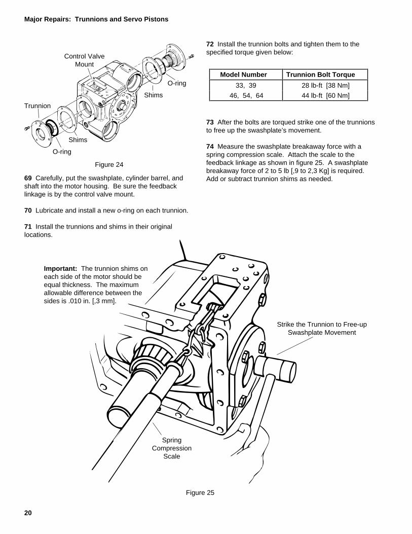
Figure 24
72 Install the trunnion bolts and tighten them to thespecified torque given below:
69 Carefully, put the swashplate, cylinder barrel, andshaft into the motor housing. Be sure the feedbacklinkage is by the control valve mount.
70 Lubricate and install a new o-ring on each trunnion.
71 Install the trunnions and shims in their originallocations.
Strike the Trunnion to Free-upSwashplate Movement
SpringCompression
Scale
Model Number Trunnion Bolt Torque
33, 39 28 lb-ft [38 Nm]
46, 54, 64 44 lb-ft [60 Nm]
73 After the bolts are torqued strike one of the trunnionsto free up the swashplate’s movement.
74 Measure the swashplate breakaway force with aspring compression scale. Attach the scale to thefeedback linkage as shown in figure 25. A swashplatebreakaway force of 2 to 5 lb [,9 to 2,3 Kg] is required.Add or subtract trunnion shims as needed.
Figure 25
Important: The trunnion shims oneach side of the motor should beequal thickness. The maximumallowable difference between thesides is .010 in. [,3 mm].
2
2
Major Repairs: Trunnions and Servo Pistons
21
I.D. Tag
Pin
RetainingRing
Servo PistonWith Spacer
Figure 26
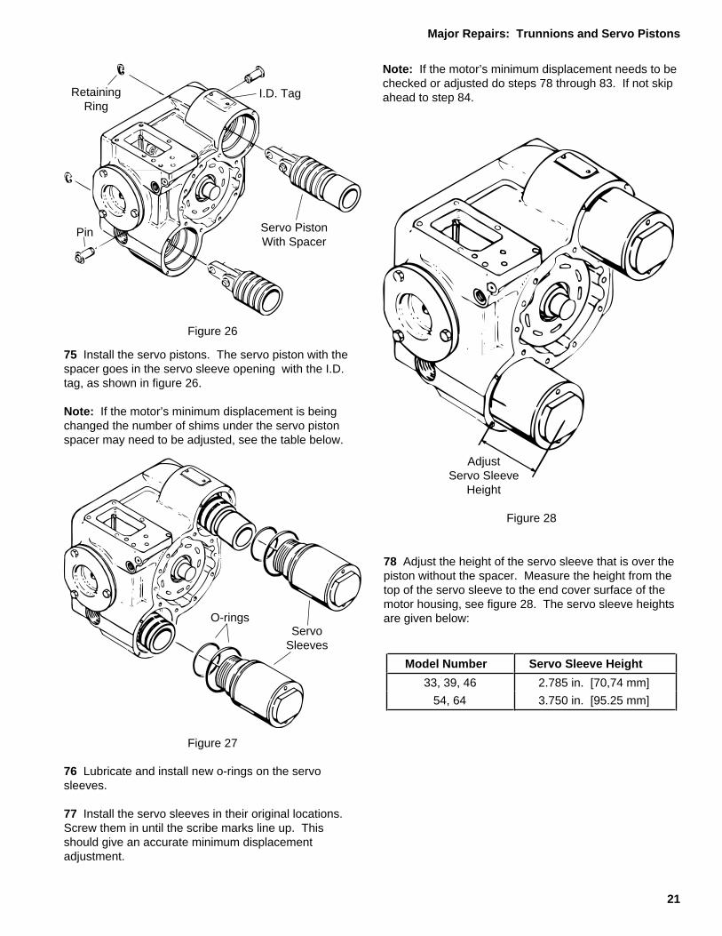
75 Install the servo pistons. The servo piston with thespacer goes in the servo sleeve opening with the I.D.tag, as shown in figure 26.
Note: If the motor’s minimum displacement is beingchanged the number of shims under the servo pistonspacer may need to be adjusted, see the table below.
Figure 27
ServoSleeves
O-rings
76 Lubricate and install new o-rings on the servosleeves.
77 Install the servo sleeves in their original locations.Screw them in until the scribe marks line up. Thisshould give an accurate minimum displacementadjustment.
Note: If the motor’s minimum displacement needs to bechecked or adjusted do steps 78 through 83. If not skipahead to step 84.
Model Number Servo Sleeve Height
33, 39, 46 2.785 in. [70,74 mm]
54, 64 3.750 in. [95.25 mm]
78 Adjust the height of the servo sleeve that is over thepiston without the spacer. Measure the height from thetop of the servo sleeve to the end cover surface of themotor housing, see figure 28. The servo sleeve heightsare given below:
Figure 28
AdjustServo Sleeve
Height
Major Repairs: Trunnions and Servo Pistons

22
Adjust forDesired
MinimumDisplacement
Figure 29
Measure DepthGauge Position
DowelPin
HoleSwashplate Stop Pad
Servo Piston SpacerMust Be Touching
Bottom of Servo Sleeve
79 Position the motor so the mounting flange end is ontop. Stand it on wooden blocks so the other servosleeve can be adjusted. While the motor is in thisposition the cylinder barrel will be setting on the woodenblocks. Be sure to protect it from damage orcontamination.
80 Tilt the swashplate to the minimum displacementposition; the servo piston spacer should touch thebottom of the servo sleeve.
81 Place the depth gauge on the mounting flangesurface so the gauge point is over the swashplate stoppad.
The depth gauge must be a precise distance from thecenter of the dowel pin hole in the motor housing, seefigure 30. Depth gauge positioning information is givenbelow:
82 Adjust the servo sleeve that is over the piston withthe spacer to get the desired depth gauge reading. Besure the swashplate is in the minimum displacementposition; the servo piston spacer must be touching thebottom of the servo sleeve. Choose the depth gaugereading for the desired minimum swashplate angle fromthe table below figure 30.
Figure 30
*The maximum swashplate angle on model 33 motors is 15.5°
MinimumSwash -
plateAngle
Model 33 * Models 39 & 46
Models 54 & 64
0° .559 [14,2] .632 [16,0] .642 [16,3]1° .526 [13,4] .599 [15,2] .609 [15,5]2° .492 [12,5] .567 [14,4] .577 [14,7]3° .459 [11,7] .534 [13,6] .544 [13,8]4° .425 [10,8] .500 [12,7] .510 [12,9]5° .390 [9,89] .467 [11,9] .476 [12,1]6° .355 [9,02] .433 [11,0] .442 [11,2]7° .320 [8,12] .398 [10,1] .407 [10,3]8° .284 [7,21] .363 [9,23] .372 [9,44]9° .248 [6,29] .328 [8,33] .336 [8,53]
10° .211 [5,37] .292 [7,42] .299 [7,61]11° .174 [4,43] .256 [6,50] .263 [6,67]12° .136 [3,47] .219 [5,57] .225 [5,72]13° .098 [2,50] .182 [4,63] .187 [4,76]14° .059 [1,50] .144 [3,67] .149 [3,78]15° .020 [,51] .106 [2,70] .110 [2,78]16° .067 [1,70] .070 [1,77]17° .028 [,71] .029 [,74]18° .000 [,00] .000 [,00]
Depth Gauge Readingin. [mm]
Model Number Distance of Depth GaugeFrom Dowel Pin Center
33, 39, 46 1.315 in. [33,40 mm]
54, 64 1.670 in. [42,42 mm]
Major Repairs: Trunnions and Servo Pistons

23
83 If the motor’s minimum displacement is beingchanged the number of shims under the servo pistonspacer may need to be adjusted. The following tableshows the required number of shims and the spacer bolt
length for each minimum swashplate angle. Theoreticaldisplacements are also given for each swashplate angle.
Important: Verifying the motor’s minimum displacementon an authorized test stand is essential.
Number of Shims Bolt Length in. [mm]
MinimumSwash -
plateAngle
Model 33 * Models39 & 46
Models54 & 64
Model 33 *Models39 & 46
Models54 & 64
0° 0 0 0 1.5 [38] 1.5 [38] 1.5 [38]
1° 0 0 0 1.5 [38] 1.5 [38] 1.5 [38]
2° 0 0 0 1.5 [38] 1.5 [38] 1.5 [38]
3° 1 1 0 1.5 [38] 1.5 [38] 1.5 [38]
4° 1 1 1 1.5 [38] 1.5 [38] 1.75 [45]
5° 2 2 1 1.75 [45] 1.75 [45] 1.75 [45]
6° 2 2 1 1.75 [45] 1.75 [45] 1.75 [45]
7° 3 3 2 1.75 [45] 1.75 [45] 2 [51]
8° 3 3 2 1.75 [45] 1.75 [45] 2 [51]
9° 4 4 2 2 [51] 2 [51] 2 [51]
10° 4 4 3 2 [51] 2 [51] 2.25 [57]
11° 5 5 3 2 [51] 2 [51] 2.25 [57]
12° 5 5 3 2 [51] 2 [51] 2.25 [57]
13° 6 6 4 2.25 [57] 2.25 [57] 2.5 [64]
14° 6 6 4 2.25 [57] 2.25 [57] 2.5 [64]
15° 7 7 4 2.25 [57] 2.25 [57] 2.5 [64]
16° 7 5 2.25 [57] 2.5 [64]
17° 8 5 2.25 [57] 2.5 [64]
18° 8 5 2.25 [57] 2.5 [64]
Swash -plateAngle
Model 33 * Model 39 Model 46 Model 54 Model 64
1° .209 [3,42} .209 [3,42] .247 [4,05] .292 [4,79] .346 [5,67]2° .418 [6,84] .418 [6,84] .494 [8,10] .585 [9,58] .692 [11,3]3° .627 [10,3] .627 [10,3] .742 [12,2] .877 [14,4] 1.04 [17,0]4° .836 [13,7] .836 [13,7] .989 [16,2] 1.17 [19,2] 1.38 [22,7]5° 1.05 [17,1] 1.05 [17,1] 1.24 [20,3] 1.46 [24,0] 1.73 [28,4]6° 1.26 [20,6] 1.26 [20,6] 1.49 [24,4] 1.76 [28,8] 2.08 [34,1]7° 1.47 [24,1] 1.47 [24,1] 1.74 [28,5] 2.06 [33,7] 2.43 [39,8]8° 1.68 [27,5] 1.68 [27,5] 1.99 [32,6] 2.35 [38,5] 2.78 [45,6]9° 1.89 [31,0] 1.89 [31,0] 2.24 [36,7] 2.65 [43,4] 3.14 [51,4]
10° 2.11 [34,6] 2.11 [34,6] 2.50 [40,9] 2,95 [48,4] 3.49 [57,2]11° 2.32 [38,1] 2.32 [38,1] 2.75 [45,1] 3.25 [53,3] 3.85 [63,1]12° 2.54 [41,6] 2.54 [41,6] 3.01 [49,3] 3.56 [58,3] 4.21 [69,0]13° 2.76 [45,2] 2.76 [45,2] 3.27 [53,5] 3.87 [63,3] 4.57 [74,9]14° 2.98 [48,9] 2.98 [48,9] 3.53 [57,8] 4.17 [68,4] 4.94 [80,9]15° 3.20 [52,5] 3.20 [52,5] 3.79 [62,1] 4.49 [73,5] 5.31 [87,0]16° 3.43 [56,2] 4.06 [66,5] 4.80 [78,7] 5.68 [93,1]17° 3.66 [59,9] 4.33 [70,9] 5.12 [83,9] 6.05 [99,2]18° 3.89 [63,7] 4.60 [75,3] 5.44 [89,1] 6.44 [105]
Theoretical Displacement vs Swashplate Anglecu.in./rev. [cu.cm./rev.]
*The maximum swashplate angle on model 33 motors is 15.5°.
Minimum Displacement Setting
24
Dowel Pin
Shipping Strap
Bolt (12)
Gasket
Figure 31
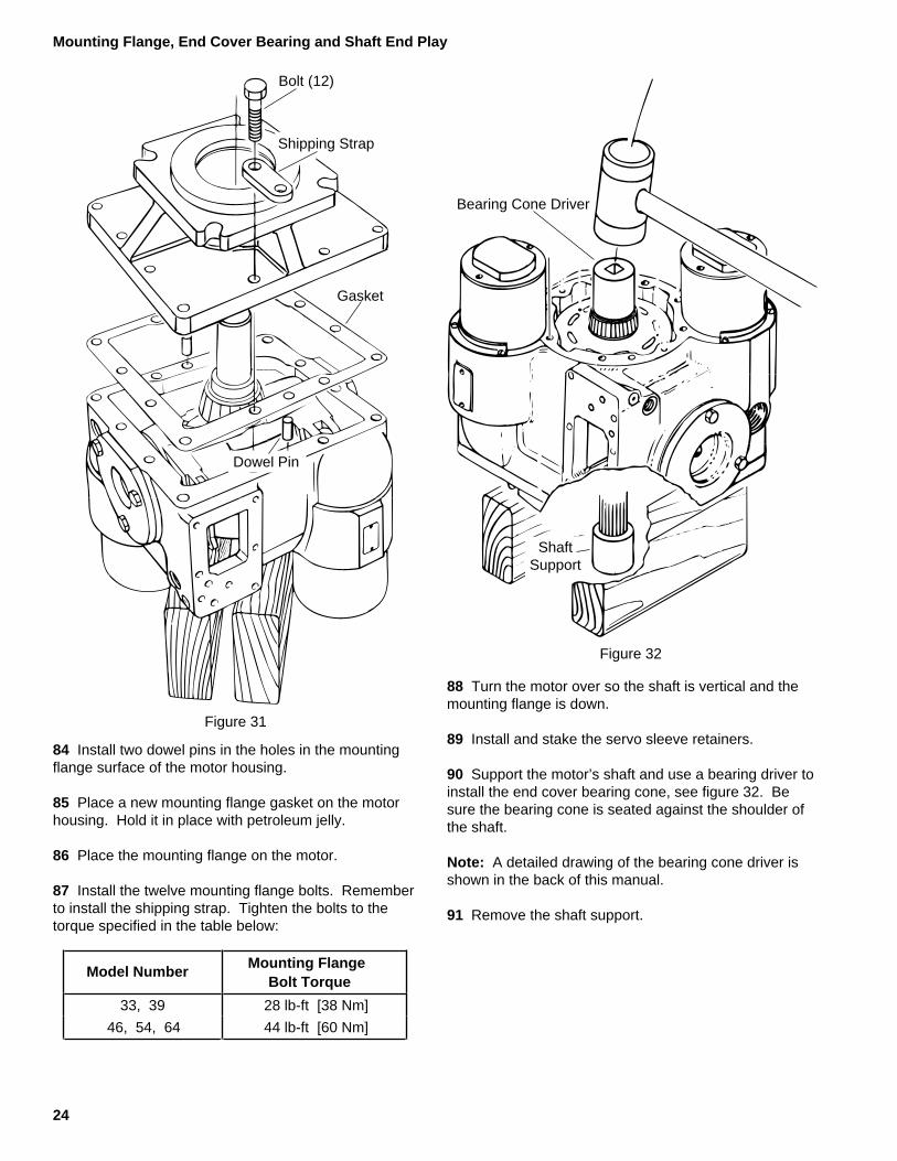
84 Install two dowel pins in the holes in the mountingflange surface of the motor housing.
85 Place a new mounting flange gasket on the motorhousing. Hold it in place with petroleum jelly.
86 Place the mounting flange on the motor.
87 Install the twelve mounting flange bolts. Rememberto install the shipping strap. Tighten the bolts to thetorque specified in the table below:
Model NumberMounting Flange
Bolt Torque
33, 39 28 lb-ft [38 Nm]
46, 54, 64 44 lb-ft [60 Nm]
Bearing Cone Driver
ShaftSupport
Figure 32
88 Turn the motor over so the shaft is vertical and themounting flange is down.
89 Install and stake the servo sleeve retainers.
90 Support the motor’s shaft and use a bearing driver toinstall the end cover bearing cone, see figure 32. Besure the bearing cone is seated against the shoulder ofthe shaft.
Note: A detailed drawing of the bearing cone driver isshown in the back of this manual.
91 Remove the shaft support.
Mounting Flange, End Cover Bearing and Shaft End Play
25
BearingCup
Shims
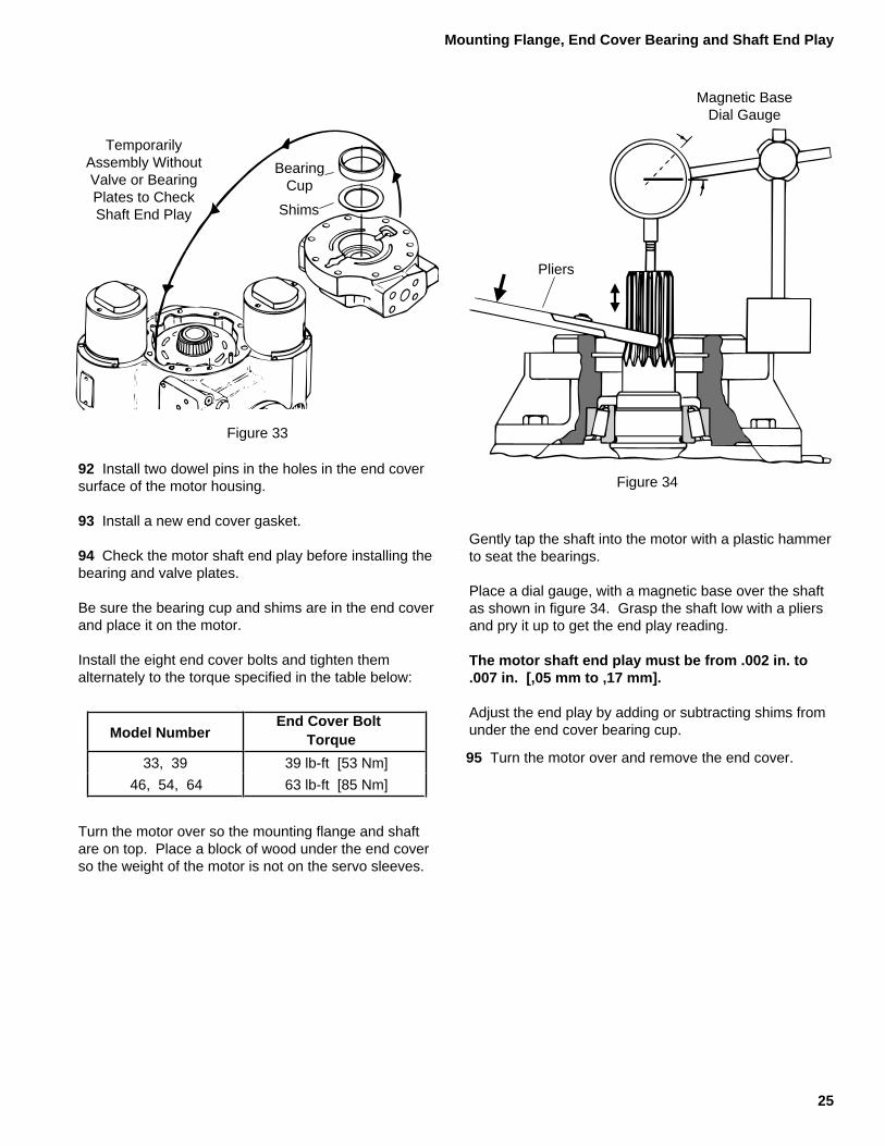
TemporarilyAssembly WithoutValve or BearingPlates to CheckShaft End Play
Figure 33
92 Install two dowel pins in the holes in the end coversurface of the motor housing.
93 Install a new end cover gasket.
94 Check the motor shaft end play before installing thebearing and valve plates.
Be sure the bearing cup and shims are in the end coverand place it on the motor.
Install the eight end cover bolts and tighten themalternately to the torque specified in the table below:
Model NumberEnd Cover Bolt
Torque
33, 39 39 lb-ft [53 Nm]
46, 54, 64 63 lb-ft [85 Nm]
Turn the motor over so the mounting flange and shaftare on top. Place a block of wood under the end coverso the weight of the motor is not on the servo sleeves.
Figure 34
Gently tap the shaft into the motor with a plastic hammerto seat the bearings.
Place a dial gauge, with a magnetic base over the shaftas shown in figure 34. Grasp the shaft low with a pliersand pry it up to get the end play reading.
The motor shaft end play must be from .002 in. to.007 in. [,05 mm to ,17 mm].
Adjust the end play by adding or subtracting shims fromunder the end cover bearing cup.
Magnetic BaseDial Gauge
Pliers
95 Turn the motor over and remove the end cover.
Mounting Flange, End Cover Bearing and Shaft End Play
26
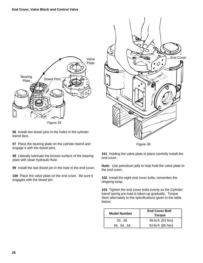
End Cover
Figure 36
101 Holding the valve plate in place carefully install theend cover.
Note: Use petroleum jelly to help hold the valve plate tothe end cover.
102 Install the eight end cover bolts, remember theshipping strap.
103 Tighten the end cover bolts evenly so the Cylinderbarrel spring pre-load is taken-up gradually. Torquethem alternately to the specifications given in the tablebelow:
ValvePlate
BearingPlate Dowel Pins
Figure 35
96 Install two dowel pins in the holes in the cylinderbarrel face.
97 Place the bearing plate on the cylinder barrel andengage it with the dowel pins.
98 Liberally lubricate the bronze surface of the bearingplate with clean hydraulic fluid.
99 Install the last dowel pin in the hole in the end cover.
100 Place the valve plate on the end cover. Be sure itengages with the dowel pin.
End Cover, Valve Block and Control Valve
Model NumberEnd Cover Bolt
Torque
33, 39 39 lb-ft [53 Nm]
46, 54, 64 63 lb-ft [85 Nm]

27
Bolt (4)
Back-up Ring
O-ring
Sq. Cut Seal
Valve Block
Hose Fittings
Hose Ass'y
Figure 37
Control ValveGasket
FeedbackLinkage
Figure 38
104 Install new o-rings and back-up rings in the groovesaround the high pressure ports as shown in figure 37.Install a square-cut seal in the groove around the lowpressure port. Use petroleum jelly to hold these sealingrings in place while the valve block is installed.
105 Position the valve block on the motor. Install thefour hex head bolts and tighten them to 28 lb-ft [38 Nm].
106 Tighten the high pressure relief valves to 25 lb-ft[34 Nm].
Tighten the low pressure relief valve, and shuttle valveplugs to 80 lb-ft [108 Nm].
Tighten the gauge port plugs and control pressure hosefittings, if used, to 17 lb-ft [23 Nm].
107 Connect the control pressure hose between themotor housing and valve block fittings, if used. Tightenboth ends to 7.5 lb-ft [10 Nm].
108 Reposition the motor so the control valve mount ison top.
109 Place a new control valve gasket on the motor.
110 Connect the feedback linkage and position thecontrol valve on the motor.
Important: When the control valve is positioned on themotor make sure the feedback linkage points towardsthe end cover.
111 Install the six hex head bolts and tighten themfinger tight.
112 Move the control lever back and forth; it shouldmove freely in both directions and self-center. If itdoesn’t, recheck the feedback linkage.
113 Tighten the six hex head bolts to 16 lb-ft [22 Nm].
Note: The control pressure hose is now obsolete. Poormotor control characteristics may be experienced whenthe motor gets control pressure from the valve block. Itis best to run a separate control pressure line from thecharge pump to the motor. If possible re-plumb theapplication so the control pressure hose is no longerused. Be sure to plug the port in the valve block.
End Cover, Valve Block and Control Valve

28
Retaining Ring
Stationary Seal
O-ring
Figure 39
Rotating Seal
115 Apply petroleum jelly to the o-ring and install it inthe rotating seal
116 Apply a light coating of clean hydraulic oil to thecleaned metal sealing surface of the rotating seal.
117 Install the rotating seal using the special pulling tool(CAS 1844).
118 Screw a 3 in. X 1/4-20 bolt into the threaded hole inthe new stationary seal. The bolt provides a convenientmeans for holding the seal.
119 Apply petroleum jelly to the o-ring that is aroundthe largest part of the stationary seal.
120 Apply a light coating of clean hydraulic oil to thecleaned metal sealing surface of the stationary seal.
121 Install the stationary seal.
122 Using the retaining ring pliers install the retainingring with the beveled side out.
Caution: Verifying the accuracy of repairs on anauthorized test stand is essential.
114 Reposition the motor so the shaft seal can beinstalled.
Note: Eaton recommends replacing the entire shaftseal. Use Shaft Seal Kit P/N 990231.
Important: The metal-to-metal sealing surfaces arecritical. Clean the areas of contact with a suitablesolvent then blow them dry. The solvent must evaporatewithout leaving a residue. Do not touch the sealingsurfaces after cleaning.
Low Clearance Bearing Puller
Model B C D E F G
33, 39, 461.0501.070
1.565 Ref.1.351.29
12°-45'13°-15'
1.9071.913
2.0202.026
54, 641.1151.135
2.071 Ref..131.125
10°-5'10°-35'
2.3102.316
2.4322.438
Material / Heat Treatment;Stentor / 45-55 Rc
Special Tools( All dimensions are given in inches.)
B .375.378
A AH
Dia.
.510
.490
1.1351.115
4.0103.990
Dia..740.760
Dia.
3/8-16 UNC2 Places
3.5103.490
.021
.041.052.072
Section A-A
Dia.C
D
E
F
G
Dia.
Dia.E
E
29
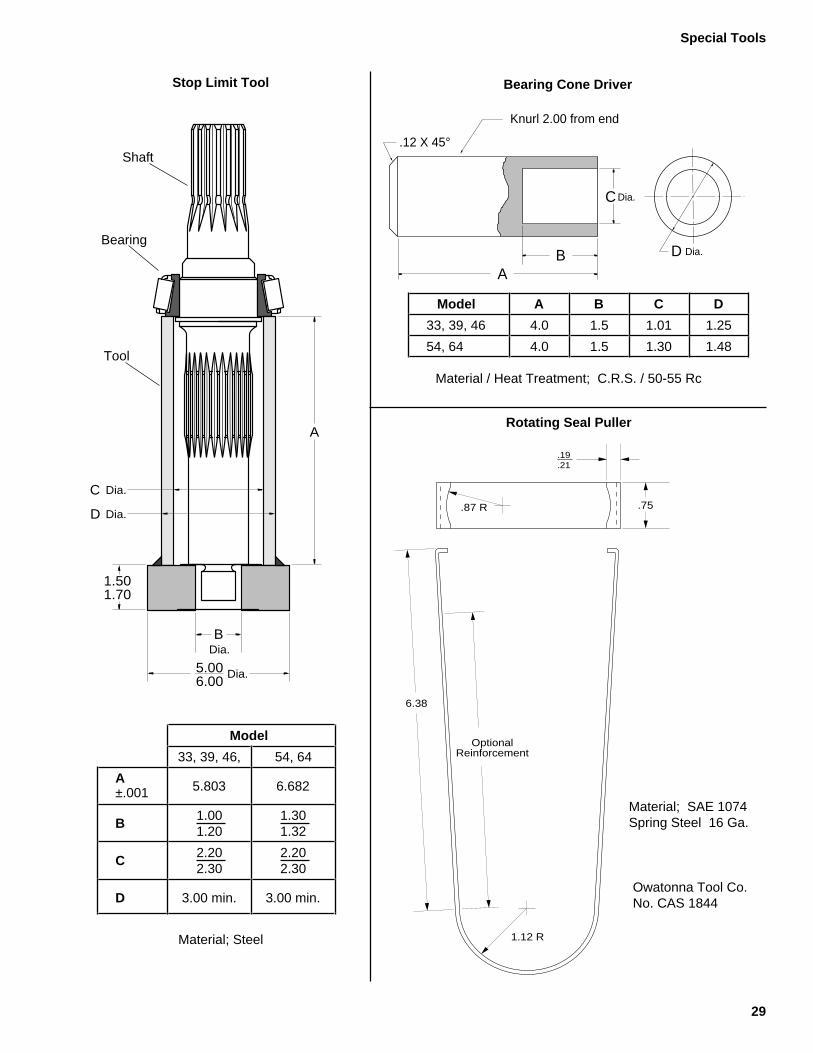
Bearing Cone DriverStop Limit Tool
A
BDia.
5.006.00
Dia.
Dia.
Dia.
C
D
1.501.70
Model
33, 39, 46, 54, 64
A ±.001 5.803 6.682
B1.001.20
1.301.32
C2.202.30
2.202.30
D 3.00 min. 3.00 min.
Material; Steel
Shaft
Bearing
Tool
D Dia.
C Dia.
BA
.12 X 45°
Knurl 2.00 from end
Model A B C D
33, 39, 46 4.0 1.5 1.01 1.25
54, 64 4.0 1.5 1.30 1.48
Material / Heat Treatment; C.R.S. / 50-55 Rc
Rotating Seal Puller
6.38
.75
.19
.21
OptionalReinforcement
1.12 R
.87 R
Owatonna Tool Co.No. CAS 1844
Material; SAE 1074Spring Steel 16 Ga.
Special Tools

30
Hydraulic Fluid Recommendations
A reputable supplier can help you make the best selection of hydraulic fluid for use inEaton hydrostatic products.
For satisfactory operation the following recommendations apply:
1. The filter system used in the hydraulic circuit should be capable of cleaning andmaintaining the hydraulic fluid to meet ISO Cleanliness Code 18/13 per SAEJ1165. This code allows a maximum of 2500 particles per milliliter greater than 5µm and a maximum of 80 particles per milliliter greater than 15 µm.
2. At normal operating temperatures optimum viscosity ranges from 80-180 SUS(16-39 cSt). Viscosity should never fall below 60 SUS (10 cSt) and, at the lowestexpected start-up temperature, should not exceed 10,000 SUS (2158 cSt).
3. The fluid should be chemically stable, incorporating rust and oxidation inhibitors.
Specific types of fluid that meet these requirements are:
• Premium quality, industrial anti-wear type hydraulic fluid
• Engine crankcase oil — SAE 10w, SAE 20w-20, SAE 30
• Automatic transmission oil
• Hydraulic transmission oil
• Synthetic fire resistant fluid — Quintolubric, Cosmolubric, or equivalent
Note: If the natural color of the fluid has become black or milky it is possible that anoverheating or water contamination problem exists.
Take level readings when fluid is cold.

31
Notes

© 2008 Eaton CorporationAll Rights ReservedPrinted in USADocument No. E-MOPI-TS007-ESupersedes 07-140November 2008
EatonFluid Power GroupHydraulics Business USA14615 Lone Oak RoadEden Prairie, MN 55344USATel: 952-937-9800Fax: 952-294-7722www.eaton.com/hydraulics
EatonFluid Power GroupHydraulics Business EuropeRoute de la Longeraie 71110 MorgesSwitzerlandTel: +41 (0) 21 811 4600Fax: +41 (0) 21 811 4601
EatonFluid Power GroupHydraulics Business Asia Pacific 11th Floor Hong Kong New World Tower 300 Huaihai Zhong Road Shanghai 200021 China Tel: 86-21-6387-9988 Fax: 86-21-6335-3912


