28
Safety and operating instructions Hydraulic breakers RX 2, 3, 4, 6, 8 www.cp.com

Safety and operating instructionsHydraulic breakers
RX 2, 3, 4, 6, 8
www.cp.com

9800 1050 01f | Original instructions2
RX 2, 3, 4, 6, 8

ContentsIntroduction. . . . . . . . . . . . . . . . . . . . . . . . . . . . . . . . . . . . . . . . . . . . . . . . . . . . . . . . . . . . . . . . . . . . . . . 5
About the Safety and operating instructions. . . . . . . . . . . . . . . . . . . . . . . . . . . . . . . . . . . . . . . 5
Safety instructions. . . . . . . . . . . . . . . . . . . . . . . . . . . . . . . . . . . . . . . . . . . . . . . . . . . . . . . . . . . . . . . . . 6Safety signal words. . . . . . . . . . . . . . . . . . . . . . . . . . . . . . . . . . . . . . . . . . . . . . . . . . . . . . . . . . . . . . . . 6Personal precautions and qualifications. . . . . . . . . . . . . . . . . . . . . . . . . . . . . . . . . . . . . . . . . . . . . . 6Carrier, precautions. . . . . . . . . . . . . . . . . . . . . . . . . . . . . . . . . . . . . . . . . . . . . . . . . . . . . . . . . . . . . . . . 7Installation, precautions. . . . . . . . . . . . . . . . . . . . . . . . . . . . . . . . . . . . . . . . . . . . . . . . . . . . . . . . . . . . 7Operation, precautions. . . . . . . . . . . . . . . . . . . . . . . . . . . . . . . . . . . . . . . . . . . . . . . . . . . . . . . . . . . . 7Maintenance, precautions. . . . . . . . . . . . . . . . . . . . . . . . . . . . . . . . . . . . . . . . . . . . . . . . . . . . . . . . . . 9Storage, precautions. . . . . . . . . . . . . . . . . . . . . . . . . . . . . . . . . . . . . . . . . . . . . . . . . . . . . . . . . . . . . . 10
Overview. . . . . . . . . . . . . . . . . . . . . . . . . . . . . . . . . . . . . . . . . . . . . . . . . . . . . . . . . . . . . . . . . . . . . . . . . 11Design and function. . . . . . . . . . . . . . . . . . . . . . . . . . . . . . . . . . . . . . . . . . . . . . . . . . . . . . . . . . . . . . 11Main parts. . . . . . . . . . . . . . . . . . . . . . . . . . . . . . . . . . . . . . . . . . . . . . . . . . . . . . . . . . . . . . . . . . . . . . 11Labels. . . . . . . . . . . . . . . . . . . . . . . . . . . . . . . . . . . . . . . . . . . . . . . . . . . . . . . . . . . . . . . . . . . . . . . . . . 11
Transport. . . . . . . . . . . . . . . . . . . . . . . . . . . . . . . . . . . . . . . . . . . . . . . . . . . . . . . . . . . . . . . . . . . . . . . . . 12
Installation. . . . . . . . . . . . . . . . . . . . . . . . . . . . . . . . . . . . . . . . . . . . . . . . . . . . . . . . . . . . . . . . . . . . . . . 12Hoses and connections. . . . . . . . . . . . . . . . . . . . . . . . . . . . . . . . . . . . . . . . . . . . . . . . . . . . . . . . . . . 12Hydraulic oil. . . . . . . . . . . . . . . . . . . . . . . . . . . . . . . . . . . . . . . . . . . . . . . . . . . . . . . . . . . . . . . . . . . . . 13Pressure adjustment. . . . . . . . . . . . . . . . . . . . . . . . . . . . . . . . . . . . . . . . . . . . . . . . . . . . . . . . . . . . . . 14Assembly. . . . . . . . . . . . . . . . . . . . . . . . . . . . . . . . . . . . . . . . . . . . . . . . . . . . . . . . . . . . . . . . . . . . . . . . 14Insertion tool. . . . . . . . . . . . . . . . . . . . . . . . . . . . . . . . . . . . . . . . . . . . . . . . . . . . . . . . . . . . . . . . . . . . 15
Operation. . . . . . . . . . . . . . . . . . . . . . . . . . . . . . . . . . . . . . . . . . . . . . . . . . . . . . . . . . . . . . . . . . . . . . . . 17Preparation before breaking. . . . . . . . . . . . . . . . . . . . . . . . . . . . . . . . . . . . . . . . . . . . . . . . . . . . . . . 17Operating. . . . . . . . . . . . . . . . . . . . . . . . . . . . . . . . . . . . . . . . . . . . . . . . . . . . . . . . . . . . . . . . . . . . . . . 17
Maintenance. . . . . . . . . . . . . . . . . . . . . . . . . . . . . . . . . . . . . . . . . . . . . . . . . . . . . . . . . . . . . . . . . . . . . 19Lubrication. . . . . . . . . . . . . . . . . . . . . . . . . . . . . . . . . . . . . . . . . . . . . . . . . . . . . . . . . . . . . . . . . . . . . . 19Every second hour. . . . . . . . . . . . . . . . . . . . . . . . . . . . . . . . . . . . . . . . . . . . . . . . . . . . . . . . . . . . . . . . 20Every day. . . . . . . . . . . . . . . . . . . . . . . . . . . . . . . . . . . . . . . . . . . . . . . . . . . . . . . . . . . . . . . . . . . . . . . 20Every week. . . . . . . . . . . . . . . . . . . . . . . . . . . . . . . . . . . . . . . . . . . . . . . . . . . . . . . . . . . . . . . . . . . . . . 21Every year. . . . . . . . . . . . . . . . . . . . . . . . . . . . . . . . . . . . . . . . . . . . . . . . . . . . . . . . . . . . . . . . . . . . . . . 21
Storage. . . . . . . . . . . . . . . . . . . . . . . . . . . . . . . . . . . . . . . . . . . . . . . . . . . . . . . . . . . . . . . . . . . . . . . . . . . 21
Disposal. . . . . . . . . . . . . . . . . . . . . . . . . . . . . . . . . . . . . . . . . . . . . . . . . . . . . . . . . . . . . . . . . . . . . . . . . . 22
Technical data. . . . . . . . . . . . . . . . . . . . . . . . . . . . . . . . . . . . . . . . . . . . . . . . . . . . . . . . . . . . . . . . . . . . 23Machine data. . . . . . . . . . . . . . . . . . . . . . . . . . . . . . . . . . . . . . . . . . . . . . . . . . . . . . . . . . . . . . . . . . . . 23Capacities. . . . . . . . . . . . . . . . . . . . . . . . . . . . . . . . . . . . . . . . . . . . . . . . . . . . . . . . . . . . . . . . . . . . . . . 23Noise declaration statement. . . . . . . . . . . . . . . . . . . . . . . . . . . . . . . . . . . . . . . . . . . . . . . . . . . . . . . 23
EC Declaration of Conformity. . . . . . . . . . . . . . . . . . . . . . . . . . . . . . . . . . . . . . . . . . . . . . . . . . . . . 25EC Declaration of Conformity (EC Directive 2006/42/EC). . . . . . . . . . . . . . . . . . . . . . . . . . . . . . 25
39800 1050 01f | Original instructions
ContentsRX 2, 3, 4, 6, 8

9800 1050 01f | Original instructions4
RX 2, 3, 4, 6, 8Safety and operating instructions

Introduction
Thank you for choosing Chicago Pneumatic brand products. For over a century, theChicago Pneumatic brand has represented performance and innovation in thepneumatic tool industry.
Today the brand is found around the world on a range of pneumatic and hydraulictools that includes breakers, rock drills, chipping hammers, clay-diggers, picks andbusters, scabblers, pumps and a whole lot more.
The Chicago Pneumatic brand is associated with powerful and reliable products thatare easy to maintain and that give good value for the money.
For more information please visit www.cp.com
Construction Tools PC ABBox 703391 27 KalmarSweden
About the Safety and operatinginstructions
The aim of the instructions is to provide you with knowledge of how to use thehydraulic breaker in an efficient, safe way. The instructions also give you advice andtell you how to perform regular maintenance on the hydraulic breaker.
Before using the hydraulic breaker for the first time you must read these instructionscarefully and understand all of them.
59800 1050 01f | Original instructions
Safety and operating instructionsRX 2, 3, 4, 6, 8

Safety instructionsTo reduce the risk of serious injury or death toyourself or others, read and understand the Safetyand operating instruction before installing,operating, repairing, maintaining, or changingaccessories on the machine.Post this Safety and operating instruction at worklocations, provide copies to employees, and makesure that everyone reads the Safety and operatinginstruction before operating or servicing themachine. For professional use only.In addition, the operator or the operator's employermust assess the specific risks that may be present asa result of each use of the machine.
Safety signal words
The safety signal words Danger, Warning andCaution have the following meanings:
Indicates a hazardous situationwhich, if not avoided, will resultin death or serious injury.
DANGER
Indicates a hazardous situationwhich, if not avoided, couldresult in death or serious injury.
WARNING
Indicates a hazardous situationwhich, if not avoided, couldresult in minor or moderateinjury.
CAUTION
Personal precautions andqualifications
Only qualified and trained persons may operate ormaintain the machine. They must be physically ableto handle the bulk, weight, and power of the tool.Always use your common sense and goodjudgement.
TransportTransport of the hydraulic breaker may only beundertaken by persons who:> are authorised to operate a crane or fork-lift truck
in conformity with the applicable nationaldirectives,
> are aware of all the relevant national safetyinstructions and accident prevention instructions
> and have read and understood the safety andtransport chapters of this manual.
Installation, storage, maintenance anddisposalInstallation, storage, maintenance and disposal ofthe hydraulic breaker may only be undertaken bypersons who:> are aware of all the relevant national safety
instructions and accident prevention instructions
> and have read and understood the Safety andoperating instructions.
OperationOperation of the hydraulic breaker may only beundertaken by qualified carrier operators. Carrieroperators are qualified if they:> are trained to operate a carrier in conformity with
national directives,
> are aware of all the relevant national safetyinstructions and accident prevention instructions
> and have read and understood the Safety andoperating instructions.
TestingTesting of the hydraulic installation must only becarried out by professional technicians. Thetechnicians must be authorised to approve ahydraulic installation in accordance with nationaldirectives.
Personal protective equipmentAlways use approved protective equipment.Operators and all other persons in the working areamust wear protective equipment, including at aminimum:> Protective helmet
> Hearing protection
> Impact resistant eye protection with sideprotection
> Respiratory protection when appropriate
> Protective gloves
> Proper protective boots
> Appropriate work overall or similar clothing (notloose-fitting) that covers your arms and legs.
9800 1050 01f | Original instructions6
RX 2, 3, 4, 6, 8Safety and operating instructions

Drugs, alcohol or medicationWARNING Drugs, alcohol or medication
Drugs, alcohol or medication may impair yourjudgment and powers of concentration. Poorreactions and incorrect assessments can lead tosevere accidents or death.►Never use the machine when you are tired or
under the influence of drugs, alcohol ormedication.
►No person who is under the influence of drugs,alcohol or medication may operate the machine.
Carrier, precautions
Before using or transporting the carrier with thehydraulic breaker attached, carefully read the carriermanufacturer's safety regulations and operatinginstructions.Make sure that the carrier is equipped with adequateprotective features, including a protective screen infront of the operator.The hydraulic breaker must only be mounted on acarrier with sufficient load capacity.Carriers without sufficient load capacity will notprovide the required degree of stability and couldeven fall over during hydraulic breaker use, causinginjury and damage.
Installation, precautions
Hydraulic systemDANGER Compressed gas, explosion
hazardThe integrated piston accumulator is pressurizedeven when the hydraulic system is shut off. Todismount the accumulator without first releasingthe nitrogen gas can cause serious personal injuryor death.►Fill the integrated piston accumulator with
nitrogen (N 2) only.
►Only authorised personnel are qualified to workwith the accumulator.
WARNING Hydraulic oil at highpressureThin jets of hydraulic oil under high pressure canpenetrate the skin and cause permanent injury.► Immediately consult a doctor if hydraulic oil has
penetrated the skin.
►Never use your fingers to check for hydraulic fluidleaks.
►Keep your face away from any possible leaks.
WARNING Hydraulic oilSpilled hydraulic oil can cause burns, accidents dueto slippery conditions and will also harm theenvironment.►Take care of all spilled oil and handle it according
to your safety and environmental regulations.
►Never dismount the hydraulic machine when thehydraulic oil is hot.
►Never run any hydraulic lines for attachment ofthe hydraulic machine through the drivers cab.
CAUTION Skin eczemaHydraulic oil can cause eczema if it comes in contactwith the skin.►Avoid getting hydraulic oil on your hands.
►Always use protective gloves when working withhydraulic oil.
►Wash hands after contact with hydraulic oil.
Assembly or disassemblyWARNING Moving parts
Risk for leaking oil and personal injury, such ascrushed hands and fingers.►Never check bores or passages with hands or
fingers.
►Any boom movements must only be done incooperation with the personnel mounting thehydraulic breaker.
► If the hydraulic breaker is mounted on a quickhitch coupling, make sure it is locked securely andall risks of the hydraulic breaker coming loose areeliminated.
Operation, precautions
DANGER Explosion hazardIf an working tool comes into contact with explosivesor explosive gases, an explosion could occur. Whenworking on certain materials and when using certainmaterials in machine parts, sparks and ignition canoccur. Explosions will lead to severe injuries or death.►Never operate the machine in any explosive
environment.
►Never use the machine near flammable materials,fumes or dust.
►Make sure that there are no undetected sourcesof gas or explosives.
79800 1050 01f | Original instructions
Safety and operating instructionsRX 2, 3, 4, 6, 8

WARNING Operating pressureIf the maximum operating pressure for the hydraulicmachine is exceeded, the accumulator can be overcharged which can result in material damage andpersonal injury.►Always run the hydraulic machine with the correct
operating pressure. See "Technical data".
WARNING Dust and fume hazardDusts and/or fumes generated or dispersed whenusing the machine may cause serious and permanentrespiratory disease, illness, or other bodily injury (forexample, silicosis or other irreversible lung diseasethat can be fatal, cancer, birth defects, and/or skininflammation).Some dusts and fumes created by drilling, breaking,hammering, sawing, grinding and other constructionactivities contain substances known to the State ofCalifornia and other authorities to cause respiratorydisease, cancer, birth defects, or other reproductiveharm. Some examples of such substances are:> Crystalline silica, cement, and other masonry
products.
> Arsenic and chromium from chemically-treatedrubber.
> Lead from lead-based paints.
Dust and fumes in the air can be invisible to thenaked eye, so do not rely on eye sight to determineif there is dust or fumes in the air.To reduce the risk of exposure to dust and fumes,do all of the following:►Perform site-specific risk assessment. The risk
assessment should include dust and fumes createdby the use of the machine and the potential fordisturbing existing dust.
►Use proper engineering controls to minimize theamount of dust and fumes in the air and tominimize build-up on equipment, surfaces,clothing, and body parts. Examples of controlsinclude: exhaust ventilation and dust collectionsystems, water sprays, and wet drilling. Controldusts and fumes at the source where possible.Make sure that controls are properly installed,maintained and correctly used.
►Wear, maintain and correctly use respiratoryprotection as instructed by your employer and asrequired by occupational health and safetyregulations. The respiratory protection must beeffective for the type of substance at issue (and ifapplicable, approved by relevant governmentalauthority).
►Work in a well ventilated area.
► If the machine has an exhaust, direct the exhaustso as to reduce disturbance of dust in a dust filledenvironment.
►Operate and maintain the machine asrecommended in the operating and safetyinstructions
►Select, maintain and replace consumables/working tools/ other accessories as recommendedin the operating and safety instructions. Incorrectselection or lack of maintenance of consumables/inserted tools/ other accessories may cause anunnecessary increase in dust or fumes.
►Wear washable or disposable protective clothesat the worksite, and shower and change into cleanclothes before leaving the worksite to reduceexposure of dust and fumes to yourself, otherpersons, cars, homes, and other areas.
►Avoid eating, drinking, and using tobaccoproducts in areas where there is dust or fumes.
►Wash your hands and face thoroughly as soon aspossible upon leaving the exposure area, andalways before eating, drinking, using tobaccoproducts, or making contact with other persons.
►Comply with all applicable laws and regulations,including occupational health and safetyregulations.
►Participate in air monitoring, medical examinationprograms, and health and safety trainingprograms provided by your employer or tradeorganizations and in accordance withoccupational health and safety regulations andrecommendations. Consult with physiciansexperienced with relevant occupational medicine.
►Work with your employer and trade organizationto reduce dust and fume exposure at the worksiteand to reduce the risks. Effective health and safetyprograms, policies and procedures for protectingworkers and others against harmful exposure todust and fumes should be established andimplemented based on advice from health andsafety experts. Consult with experts.
►Residues of hazardous substances on the machinecan be a risk. Before undertaking any maintenanceon the machine, clean it thoroughly.
WARNING Electric shockThe hydraulic breaker is not insulated against electriccurrent. If the hydraulic breaker come in contactwith electric circuits or other electrical powersources, there is a risk of severe injury or death.►Never work in the proximity of electric circuits or
other electrical power sources.
►Make sure there are no hidden electric circuits inyour working area.
9800 1050 01f | Original instructions8
RX 2, 3, 4, 6, 8Safety and operating instructions

WARNING ProjectilesFailure of the work piece, of accessories, or even ofthe hydraulic breaker itself may generate highvelocity projectiles. During breaking, splinters, orother particles may become projectiles and causebodily injury by striking the operator or otherpersons. Also, breakage of the work piece,accessories, or the working tool may generate highvelocity projectiles that can cause bodily injury. Inaddition, objects falling from a height can causebodily injury. To reduce risks:►Close off the working area.
►Before starting, make sure that no persons are inthe danger area, 20 meters both horizontally andvertically from the hydraulic breaker.
► Immediately switch off the hydraulic breaker whenpersons are present in the danger area.
►Press the working tool against the working surfacebefore you start.
►Never operate unless the working tool is retainedin the hydraulic breaker with a proper toolretainer.
WARNING Noise hazardHigh noise levels can cause permanent and disablinghearing loss and other problems such as tinnitus(ringing, buzzing, whistling, or humming in theears). To reduce risks and prevent an unnecessaryincrease in noise levels:►Risk assessment of these hazards and
implementation of appropriate controls isessential.
►Operate and maintain the machine asrecommended in these instructions.
►Select, maintain and replace the working tool asrecommended in these instructions.
► If the machine has a silencer, check that it is inplace and in good working condition.
►Always use hearing protection.
►Use damping material to prevent work piecesfrom 'ringing'.
Maintenance, precautions
WARNING Involuntary startAn involuntary start of the hydraulic breaker can leadto severe injuries.►Follow the instructions in the carrier manual to
prevent involuntary start of the hydraulic breaker.
► Installation of a start circuit on the hydraulicbreaker must be made in a way that avoids anyunintentional starts.
►A foot pedal on the carrier must be equipped witha protection cover.
WARNING Hydraulic system under highpressureMaintenance work on a hydraulic breaker underpressure can lead to severe injuries. Connectionscan loosen suddenly, parts can suddenly move andhydraulic oil can be ejected.►Depressurise the hydraulic system before
performing maintenance on the hydraulic breakeror the carrier.
WARNING Machine modificationAny machine modification may result in bodilyinjuries to yourself or others.►Never modify the machine. Modified machines
are not covered by warranty or product liability.
►Always use original parts, cutting blades/workingtools, and accessories.
►Change damaged parts immediately.
►Replace worn components in good time.
CAUTION Hot working toolThe tip of the working tool can become hot andsharp when used. Touching it can lead to burns andcuts.►Never touch a hot or sharp working tool.
►Wait until the working tool has cooled downbefore carrying out maintenance work.
WARNING Working tool hazardsAccidental engagement of the start and stop deviceduring maintenance or installation can cause seriousinjuries, when the power source is connected.►Never inspect, clean, install, or remove the
working tool while the power source isconnected.
99800 1050 01f | Original instructions
Safety and operating instructionsRX 2, 3, 4, 6, 8

Storage, precautions
WARNING Hydraulic breaker andworking tool are heavyIf the breaker or working tool topple over or falldown it can result in material damage and personalinjury.►Store the hydraulic breaker and the working tool
so that falling or rolling down is prevented.
9800 1050 01f | Original instructions10
RX 2, 3, 4, 6, 8Safety and operating instructions

OverviewTo reduce the risk of serious injury or deathto yourself or others, read the Safetyinstructions section found on the previouspages of this manual before operating themachine.
Design and function
RX is a range of rigmounted hydraulic breakersdesigned for all kinds of demolition works. No otheruse is permitted.The hydraulic breaker is operated from the driver'scab of the carrier using the carrier's hydraulic system.The breaker frequency is controlled by the oil flowfrom the carrier.
Main parts
A
B
C
D
E
A. Hammer boxB. Percussion unitC. Gasfilling valveD. Tool retainerE. Split pin
Labels
The machine is fitted with labels containingimportant information about personal safety andmachine maintenance. The labels must be in suchcondition that they are easy to read. New labels canbe ordered from the spare parts list.
119800 1050 01f | Original instructions
Safety and operating instructionsRX 2, 3, 4, 6, 8

Data plateA
B
C
D E
A. Machine type
B. Maximum permitted compressed air pressure
C. Serial number
D. The warning symbol together with the booksymbol means that the user must read thesafety and operating instructions before themachine is used for the first time.
E. The CE symbol means that the machine isEC-approved. See the EC declaration which isdelivered with the machine for moreinformation. If the CE symbol is missing, itmeans that the machine is not EC-approved.
Noise level label
WA
xxx dB
The label indicates the guaranteed noise levelcorresponding to EC-directive 2000/14/EC. See"Technical data" for accurate noise level.
Labels on the accumulator
Read through the overhaul instructions carefullybefore servicing or charging.
The accumulator must only be charged withNitrogen.NOTICE Only certified personnel are allowed towork with the accumulator.
TransportWARNING Falling breaker can cause
injuries►Place the hydraulic breaker in a safe position
where it can not fall over and cause damage.
Carefully check that the carrier is stable enoughwhen transporting or performing maintenance orother kind of work on the hydraulic breaker. Thehydraulic breaker is delivered in a box. To lift out thehydraulic breaker in a safe way, use the lifting eye.
InstallationBefore installing the hydraulic breaker on the carrieror operating it, read the operation manual and safetyinstructions provided by the carrier manufacturer.Follow all instructions.The carrier must have the appropriate hydraulicsystem for operation of the breaker.If the carrier is too large for the hydraulic breaker itmay lead to broken working tools and increasedwear. See "Technical data" for choosing suitablecarrier.The safety equipment in the hydraulic system mustbe checked for quality (CE mark, etc.), suitability andfunctionability by a professional or authorisedsupervisor before use.
Hoses and connections
WARNING Whipping hydraulic hoseHydraulic hoses under pressure can whipuncontrollably if screws loosen or are loosened. Awhipping hydraulic hose can cause severe injuries.►Depressurize the hydraulic system before
loosening the connection of a hydraulic hose.
►Tighten the nuts on the connections of thehydraulic hoses to the required torque.
9800 1050 01f | Original instructions12
RX 2, 3, 4, 6, 8Safety and operating instructions

Type of nipple: Chicago Pneumatic JIC standardnipple. The nipple dimensions can be found in theSpare parts list.The quality of the hydraulic hoses should be 2SC(according to EN 857) or better when connectingthe breaker to the carrier. If quick couplings are tobe used, we recommend using the "Flat Face" quickcoupling. This type is sturdy and easy to clean. Thequick couplings pressure class must agree with thecarrier's working pressure.Always clean the quick couplings before mountingor dismounting. Always plug hoses and hose nippleswith tight and clean plugs when dismounting.
Hose connections
D
A
B
C
A. Tank line
B. Pressure line
C. Pressure for CP-lube
D. Central lubrication point
Hose connectionsTank, return lineCentral lubrication
Symbol
M22 x 1.5G ¼ in.RX 2M26 x 1.5G ¼ in.RX 3M26 x 1.5G ¼ in.RX 4M26 x 1.5G ¼ in.RX 6M26 x 1.5G ¼ in.RX 8
Hose connectionsPressure forCP-Lube
Pressure tobreaker
Symbol
-M22RX 2-M26RX 3
M14 x 1.5M26RX 4M14 x 1.5M26RX 6M14 x 1.5M26RX 8
Tightening torque for pressure and return hose150 NmRX 2150 NmRX 3150 NmRX 4150 NmRX 6210 NmRX 8
NOTICE The tightening torques in the table aboveare valid when the pressure and return hose aremounted directly on the hydraulic breaker'sconnection nipple. If the pressure and return hoseare connected with an additional connection nipple,another tightening torques must be used.
Hydraulic oil
Normally the type of hydraulic oil the carrier is usingalso works for the hydraulic breaker. When ahydraulic breaker is connected to the carrier, thehydraulic oil will get contaminated faster. Check andfollow the carrier's instructions for changing oil andoil filter.It is common to change the oil filter more frequentlywhen a hydraulic breaker is installed.NOTICE When the machine is delivered it containssome mineral based hydraulic oil. Before connectingto the carrier's hydraulic system, check which typeof hydraulic oil the carrier is using. Mixing differenttypes of hydraulic oil may destroy the lubricationquality which can lead to machine damage.In order to protect the environment we recommendthe use of biologically degradable hydraulic oil.
139800 1050 01f | Original instructions
Safety and operating instructionsRX 2, 3, 4, 6, 8

Viscosity15-100 cStViscosity (permitted)
NOTICE Always use clean oil and fillingequipment.
Pressure adjustment
To ensure that the accumulator and hammer are notoverloaded, a separate pressure relief valve shouldbe installed, see picture below. It is set at a value of30 bar over the hammer’s maximum operatingpressure. If the carrier’s breaker circuit is alreadyequipped with a pressure limiting valve, no extravalve is necessary.
P
M
T
P T
Assembly
WARNING Falling breaker can causeinjuries►Place the breaker in a safe position where it can
not fall over and cause damage.
Preparation1. Place the breaker in a position where it is easy
and safe to mount the adapter plate.
Mounting the adapter plate2. Place a locking washer pair on each screw.
3. Tighten the screws with an spanner.
4. Always use NORDLOCK™ washers under boltand nut (NORDLOCK™ is a registered trademarkof Nord-Lock AB).
5. Tightening torqueAdapter plate200 NmRX 2200 NmRX 3390 NmRX 4390 NmRX 6390 NmRX 8
Connecting the breaker to the carrier6. Place the breaker in a safe way at installation.
9800 1050 01f | Original instructions14
RX 2, 3, 4, 6, 8Safety and operating instructions
7. Carefully lower the stick of the boom into theadapter.
WARNING Moving parts can crushand cut►Never check bores or passages with hands or
fingers.
An assistant should direct the movement of thedipper arm until the bores in the dipper arm areflush with those in the adapter.Agree with the assistant on clear hand signalsfor use during the mounting procedure.
8. Insert the pin and lock
9. Lift up the hydraulic breaker using the boom.
10. Extend the bucket cylinder until the bore in thetoggle is flush with those in the adapter. Inserttoggle pin and lock.
11. After mounting the breaker, carefully extend andretract the bucket cylinder to its full extent ineach direction. It is important that the cylindercan be fully extended and retracted without anydifficulty.
Connecting the hydraulic hose12. Circulate the hydraulic oil before connecting the
hydraulic breaker. This is to make sure that thehydraulic oil is clean. Use the same routine whenchanging the hydraulic oil hose. For furtherinformation see "The hydraulic oil".
13. Connect the pressure and return hose.
14. Run the hydraulic oil through the carrier's oilfilter for approximately 3 minutes to make surethat the hoses are clean.
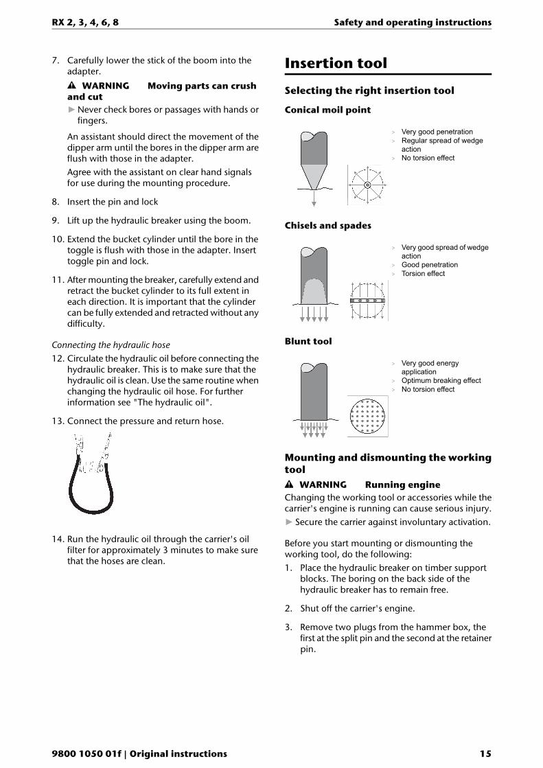
Insertion tool
Selecting the right insertion tool
Conical moil point
> Very good penetration> Regular spread of wedge
action> No torsion effect
Chisels and spades
> Very good spread of wedgeaction
> Good penetration> Torsion effect
Blunt tool
> Very good energyapplication
> Optimum breaking effect> No torsion effect
Mounting and dismounting the workingtool
WARNING Running engineChanging the working tool or accessories while thecarrier's engine is running can cause serious injury.►Secure the carrier against involuntary activation.
Before you start mounting or dismounting theworking tool, do the following:1. Place the hydraulic breaker on timber support
blocks. The boring on the back side of thehydraulic breaker has to remain free.
2. Shut off the carrier's engine.
3. Remove two plugs from the hammer box, thefirst at the split pin and the second at the retainerpin.
159800 1050 01f | Original instructions
Safety and operating instructionsRX 2, 3, 4, 6, 8

Dismounting the working tool:1. Drive out the spring pin by using a break pin
punch and a hammer. Press the retainer pin outfrom the hole at the back upwards until you canremove it through the hole on the front side.
NOTICE Dismount the working tool with alifting strap to reduce the risk of crushed bodyparts. Some working tools are heavy, thereforelift out the working tool in a safe way.
2. Check that the spring pin is not worn out ordamaged. Change if necessary.
Mounting the working tool:1. Clean and lubricate the bushing plentifully. This
is especially important when mounting a newworking tool.
2. Mount the working tool.
3. Rotate the working tool to spread the grease.
4. Mount the retainer pin, and make sure it remainsin position so it not falls through the boring atthe back.
5. Drive in the spring pin by using a break pinpunch and a hammer, until it is flushed with thepercussion unit.
9800 1050 01f | Original instructions16
RX 2, 3, 4, 6, 8Safety and operating instructions

OperationNOTICE The hydraulic breaker or the working toolis not to be used as a lifting device. When liftingheavy components use the hook on the carrier arm.
Preparation before breaking
Operating temperaturesThe operating temperatures of the hydraulic breakerare between -20ºC (-4ºF) and + 80ºC (+176ºF).
CAUTION Temperature hazardThe hydraulic breaker and the hydraulic oil systemof the carrier can be damaged if the hydraulic breakeris used at higher or lower temperatures.►Only start the hydraulic breaker when the
hydraulic oil has reached the proper operatingtemperature.
► If the ambient temperature is below – 20ºC (-4ºF),you must warm up the working tool and thehydraulic breaker before use.
► If the oil temperature exceeds + 80ºC (+176ºF),you must not use the hydraulic breaker as the oilquality becomes inadequate which severelyshortens the life time of seals and O-rings.
Engine rpmToo high engine rpm only results in increased fuelconsumption and increased oil temperature. Adaptthe engine rpm to the recommended value to givethe correct operating oil flow.
Operating
Risk areaBefore starting the hydraulic breaker, make sure thatno persons are in the risk area, 20 meters bothhorizontally and vertically from the hydraulicbreaker.
20 m
BreakingCAUTION Machine and tool hazard
Continuous operation at full extension and/orretraction can result in damage to the hydrauliccylinders.►Always avoid operating the breaker with the
cylinders fully extended or retracted.
►Reposition the carrier and/or boom to avoid fullyextended or retracted cylinders.
►Pay attention and look at what you are doing.
Never start the hydraulic breaker until both carrierand the hydraulic breaker are in the correct position.
179800 1050 01f | Original instructions
Safety and operating instructionsRX 2, 3, 4, 6, 8

♦ Direct the hydraulic breaker in a position 90°towards the object.
♦ Start near the edge and work your way in towardsthe middle. Never start in the middle of largeobjects.
♦ Never run the hydraulic breaker longer then 15seconds on the same spot. Move the working toolto a new position if the object does not break.
♦ Never bend with the working tool.
♦ Use the correct feed pressure. When the feedpressure is correct the hydraulic breaker is workingat its best and the vibrations are at a minimum.Also the wear on the bushing and inserted tool iskept to a minimum.
♦ Listen to the sound from the hydraulic breaker.The sound changes if there is any bendingbetween the working tool and bushing.
♦ Never run the breaker with the boom cylinders attheir end positions. It may cause damage to thecarrier.
9800 1050 01f | Original instructions18
RX 2, 3, 4, 6, 8Safety and operating instructions

♦ Avoid idling strokes; it causes wear on bothworking tool and tool retainers.
Use under water♦ Never use the hydraulic breaker under water.
This would seriously damage the hydraulic breakerand may damage the whole hydraulic installation.
MaintenanceIt is essential that regular maintenance is performedto maintain the breakers maximum efficiency.Equipment that is insufficiently maintained can bedangerous for both the operator and persons nearthe breaker. Make sure that regular maintenanceroutines with lubrication are followed to keep theequipment safe and efficient.
Lubrication
Lubricate the chisel shank thoroughly every twohours using high-temperature grease such asgenuine chisel grease from your supplier. This alsolubricates the bushing and the tool holder; 5-10pumps of the grease gun is sufficient. Stop whenthe grease starts to emerge at the chisel holder orbetween the chisel and the bushing.
WARNING Running engineIf the carrier's engine is running when lubricatingthe chisel by hand there is a risk of severe accidents.►Always switch off the carrier's engine to avoid
accidents.
During lubrication, the chisel must be pressedagainst the hammer piston so that the spacebetween piston and the chisel does not fill withgrease.
WARNING Explosion hazardUse of other gases than Nitrogen (N2) can cause anexplosion.►Charge the accumulator with Nitrogen (N2) only!
CP supplies a service box containing all necessarytools and parts required to service the pistonaccumulator. See the Spare parts list.If the hammer's performance begins to deteriorate,we recommend that you check the pressure in thepiston accumulator.NOTICE The pressure must be checked with thehammer at a working temperature of 60º-70ºC.To measure the pressure, bring down the hammerwith no pressure on the chisel. Detach the plug fromthe charge valve (G) and connect the test pressuregauge.The piston accumulator only needs to be filled if thepressure falls below the minimum level.
Filling1. Connect pressure relief valve (B) to gas bottle
valve (A).
2. Connect gas hose (C) to pressure relief valve (B)as shown in figure.
3. Close pressure relief valve (B).
4. Open gas bottle valve (A).
5. Remove the plug from the charge valve (G).
6. Guide the nozzle of the hose (C) into the chargevalve.
7. Carefully open the relief valve (B).
8. Fill the piston accumulator.
9. Read the pressure on the pressure gauge (D).
10. Close the pressure relief valve when the desiredpressure has been reached.Pull the gas hose out of the charge valve (G) andfit the plug.
199800 1050 01f | Original instructions
Safety and operating instructionsRX 2, 3, 4, 6, 8

11. Close gas bottle valve (A).
G
C
B
D
A
Checking and reducing the gas pressure1. Always use the gas hose (C) and the pressure
gauge (D) when checking the gas pressure.
2. Connect the gas hose to the pressure gauge.
3. Remove the plug from the charge valve (G).
4. Press the nozzle of the gas hose into the chargevalve and read the pressure.
5. Reduce the pressure by repeatedly inserting andremoving the nozzle.
NOTICE Only the nozzle may be used to reducethe pressure. Never use pins, screwdrivers etc. asthese can damage the charge valve.
Every second hour
Regularly lubricate the working tool, the tool retainerand the bushings.
Lubricating with a grease gunWARNING Hot working tool during
operation and a period of time after use.►Avoid contact with the working tool.
WARNING Hot hydralic breaker duringoperation and a period of time after use.►Avoid contact with the hydralic breaker.
CAUTION Skin eczemaGrease can cause eczema when it comes in contactwith the skin.►Avoid getting grease on your hands. Wash
thoroughly after contact.
1. Press the working tool against the piston so thatthe space between the piston and the workingtool does not fill with grease.
2. Lubricate the working tool's shank plentifullywhile pressing the working tool against thesurface to avoid filling the cavity with grease. Ifthe cavity is filled with grease when the hydraulicbreaker is started, the lower seals may bedamaged.
When the working tool shank is exposed to highpressure and high temperatures a standard type ofgrease will melt and run. To avoid this always use agenuine working tool grease from your supplier.
Central lubrication systemWe recommend Chicago Pneumatic's centrallubrication system. When this system is fitted on thecarrier, grease is pumped continuosly from alubrication container on the carrier to the breakerwhen the breaker is activated. This increases the lifeof the tool bushings and insertion tools considerably.
Every day
♦ Check the tool retainer and split pin.
♦ Check that hoses, couplings and accumulator arein a good condition.
♦ Check that bolts and connections are free fromdamage and properly tightened. See tighteningtorques in the spare parts list.
♦ Refill the central lubricating system.
9800 1050 01f | Original instructions20
RX 2, 3, 4, 6, 8Safety and operating instructions

Every week
♦ Clean the hydraulic breaker carefully.
♦ Check the wear bushing's wear and maximuminner wear limits.
A
The wear bushing must be replaced when theinner diameter (A) has reached its maximum wearlimit, see section "Wear limits" and "Replacingthe working tool bushing".
♦ Check the working tool for wear.The working tool must be replaced when theouter diameter (B) has reached its minimum wearlimit. See section "Wear limits".
B
Too large clearance can make the working toolbreak and the piston can be damaged.
♦ Check the breaker and the adapter plate for cracksand wear.
♦ Check that the accumulator screws are properlytightened. The correct tightening torque is foundin the spare parts list.
The working tool may never be sharpened byforging. Sharpening must only be performed bymilling, grinding, or turning.
Wear limits
B mm (in.)A mm (in.)39 (1.54)45 (1.77)RX 249 (1.93)55 (2.17)RX 359 (2.32)65 (2.56)RX 467 (2.64)73 (2.87)RX 677 (3.03)83 (3.27)RX 8
Replacing the working tool bushingThe working tool bushing is kept in place by the toolretainer. A new bushing has a slip fit.
1. If a worn out bushing is stuck, use a slidinghammer to remove it.
2. Carefully clean the bore and the bushing seatarea.
3. Lubricate and mount the bushing.
4. Use a plastic sledgehammer to insert thebushing.
5. Keep the bushing in position with help of thetool retainer.
Every year
Overhauling must be done after one year ofcontinuous operation. Overhauling must for safetyreasons be performed by authorised personnel atan authorised workshop.
StorageWARNING Falling breaker can cause
injuries►Place the hydraulic breaker in a safe position
where it can not fall over and cause damage.
If the hydraulic breaker is not used for a long time,the following points have to be considered to protectthe hydraulic breaker from corrosion:
219800 1050 01f | Original instructions
Safety and operating instructionsRX 2, 3, 4, 6, 8

1. Clean the hydraulic breaker carefully.
2. Dismount the working tool and lubricate thefront part of the piston, wear bushing, and theretainer pin.
3. Store the hydraulic breaker in a dry place.
Always keep the breaker in an upright position, ifstored for a long time.
DisposalA used machine must be treated and scrapped insuch a way that the greatest possible portion of thematerial can be recycled and any negative influenceon the environment is kept as low as possible.Before a used machine is scrapped it must beemptied and cleaned from all hydraulic oil. Theremaining hydraulic oil must be deposited and anynegative influence on the environment is to be keptas low as possible.
9800 1050 01f | Original instructions22
RX 2, 3, 4, 6, 8Safety and operating instructions

Technical data
Machine data
RX 8RX 6RX 4RX 3RX 28460 050 428460 0500 418460 0500 408460 0500 398460 0500 38Part number816 (370)600 (272)470 (213)328 (149)207 (94)Service weight, lb (kg)660 (300)470 (214)370 (168)265 (120)165 (75)Delivery weight, lb (kg)
11,500-26,500(5.2-12.0)
9,300-19,800(4.2-9.0)
6,400-13,200(2.9-6.0)
4,600–9,900(2.1-4.5)
2,900–6,600(1.3-3.0)
Suitable carrier weight class,lb (tonnes)
16.3(415)
15.0(380)
13.8(350)
12.6(320)
10.4(265)
Working length of workingtool in standard version, in.(mm)
3.1 (80)2.8 (70)2.4 (62)2.0 (52)1.7 (42)Working tool diameter, in.(mm)
Easy PowerEasy PowerEasy PowerEasy PowerEasy PowerStart up mode3⁄5 (15)3⁄5 (15)3⁄5 (15)3⁄5 (15)½ (12)Hose inside diameter P,
in.(mm)3⁄5 (15)3⁄5 (15)3⁄5 (15)3⁄5 (15)½ (12)Hose inside diameter T, in.
(mm)
Capacities
RX 8RX 6RX 4RX 3RX 215.9-23.8(60-90)
11.9-19.8(45-75)
9.2-15.9(35-60)
7.9–13.2(30-50)
4.0–9.2(15-35)
Oil flow, gpm (l/min)
530-1,000530-1,200520-1,300670–1,500560–1,600Impact rate, bpm1,740–2,175(120-150)
1,450–2,030(100-140)
1,595–2,030(110-140)
1,595–2,030(110-140)
1,595–1,885(110-130)
Operating pressure, psi (bar)
231814128Maximum hydraulic input power, kW2,610(180)2,465(170)2,465(170)2,465(170)2,320 (160)Pressure relief valve on carrier, psi (bar)174(12)160(11)203(14)232(16)203(14)Piston accumulator gas pressure (min, at
operating temperature 140-158°F (60-70°C)), psi (bar)
239(16.5)218(15)276(19)297(20.5)268(18.5)Piston accumulator gas pressure (max, atoperating temperature 140-158°F (60-70°C)), psi (bar)
435(30)363(25)218(15)363(25)363(25)Back pressure acceptance, psi (bar)
Noise declaration statement
RX 8RX 6RX 4RX 3RX 28786858381Sound pressure 1
dB(A)115114113111109Sound power 2 dB(A)
1 Sound pressure level according to EN ISO 3744 in accordance with directive 2000/14/EC at 10 metres distance.2 Guaranteed sound power according to EN ISO 3744 in accordance with directive 2000/14/EC inclusive spreadin production.These declared values were obtained by laboratory type testing in accordance with the stated directive orstandards and are suitable for comparison with the declared values of other tools tested in accordance withthe same directive or standards. These declared values are not adequate for use in risk assessments and valuesmeasured in individual work places may be higher. The actual exposure values and risk of harm experiencedby an individual user are unique and depend upon the way the user works, in what material the breaker isused, as well as upon the exposure time and the physical condition of the user, and the condition of thebreaker.
239800 1050 01f | Original instructions
Safety and operating instructionsRX 2, 3, 4, 6, 8

We, Construction Tools PC AB, cannot be held liable for the consequences of using the declared values, insteadof values reflecting the actual exposure, in an individual risk assessment in a work place situation over whichwe have no control.
9800 1050 01f | Original instructions24
RX 2, 3, 4, 6, 8Safety and operating instructions

EC Declaration of Conformity
EC Declaration of Conformity (EC Directive 2006/42/EC)
We, Constructions Tools PC AB, hereby declare that the machines listed below conform to the provisions ofEC Directive 2006/42/EC (Machinery Directive) and 2000/14/EC (Noise Directive).
Weight (kg)Pmax (bar)Measured soundpower level [dB(A)]
Guaranteed soundpower level [dB(A)]Hydraulic breaker
75130108109RX 2120140110111RX 3168140112113RX 4214140113114RX 6300150114115RX 8
Technical Documentation authorised representative:Conny SjöbäckConstructions Tools PC ABDragonvägen 2KalmarGeneral Manager:Jenny Hassan
Manufacturer:Constructions Tools PC ABBox 703391 27 KalmarSwedenPlace and date:Kalmar, 2012-04-23
259800 1050 01f | Original instructions
Safety and operating instructionsRX 2, 3, 4, 6, 8

9800 1050 01f | Original instructions26
RX 2, 3, 4, 6, 8

279800 1050 01f | Original instructions
RX 2, 3, 4, 6, 8

2015-07 | No. 9800 1050 01f© Copyright Construction Tools PC AB


