CR46 Farmi Forest Corporation Ahmolantie 6 FIN-74510 Iisalmi, Finland Tel. +358 (0)17 83 24 400 info@farmiforest.fi www.farmiforest.fi PROFI STANDARD OPERATION, MAINTENANCE AND SPARE PARTS MANUAL READ THIS OPERATION AND MAINTENANCE MANUAL CAREFULLY BEFORE USING THE MACHINE FROM MACHINE: CL00001 58233380 A-EN-241016-ER HYDRAULIC CRANE TRANSLATION OF THE INSTRUCTION MANUAL
READ THIS OPERATION AND MAINTENANCE MANUAL CAREFULLY BEFORE USING THE MACHINE
FROM MACHINE: CL00001 58233380 A-EN-241016-ER
HYDRAULIC CRANE
TRANSLATION OF THE INSTRUCTION MANUAL
CR46
2
CR46
3
When ordering spare parts, please indicate machines type from the machine plate, serial number, spare parts order number, description and quantity required. Example. CR46, 54566000, slide bearing 1 pc
TABLE OF CONTENTS
PRODUCT WARRANTY 4
GENERAL SAFETY INSTRUCTIONS 6
TECHNICAL DATA 11
TECHNICAL DATA 12
STICKERS AND PLATES 13
ASSEMBLY AND MOUNTING 14
COMMISSIONING 15
PRACTICE RUNS 16
DETACHING THE CRANE 16
STORAGE INSTRUCTIONS 17
MAINTENANCE 17
MAINTENANCE TABLE 19
LUBRICATION 20
TROUBLE SHOOTING 21
TESTING THE STABILITY 22
DETERMINING THE STAND-STABILITY BY CALCULATION 22
PRESSURE RELIEF VALVES 24
HYDRAULICS 25
CONNECTING THE ON/OFF VALVE (60 l) 26
INSTALLATION INSPECTION RECORD 27
ANNUAL INSPECTION RECORD 28
200001774 CR46 30
13465710 SLEWING DEVICE AND COLUMN 32
200001637 LIFTING BOOM 34
200001773 FOLDING BOOM 36
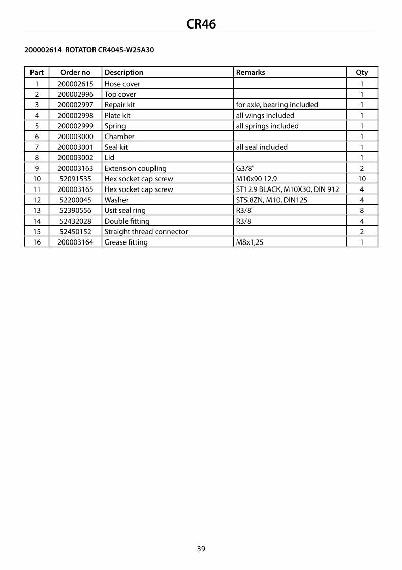
200002614 ROTATOR CR 404S-W25A30 38
200001717 CROSS LINK, WITHOUT BRAKE 40
200001712 CROSS LINK, WITH BRAKE 41
200001715 CROSS LINK, WITH DUAL BRAKE 42
200002801 TIMBER GRAPPLE PTK021S / CR300 44
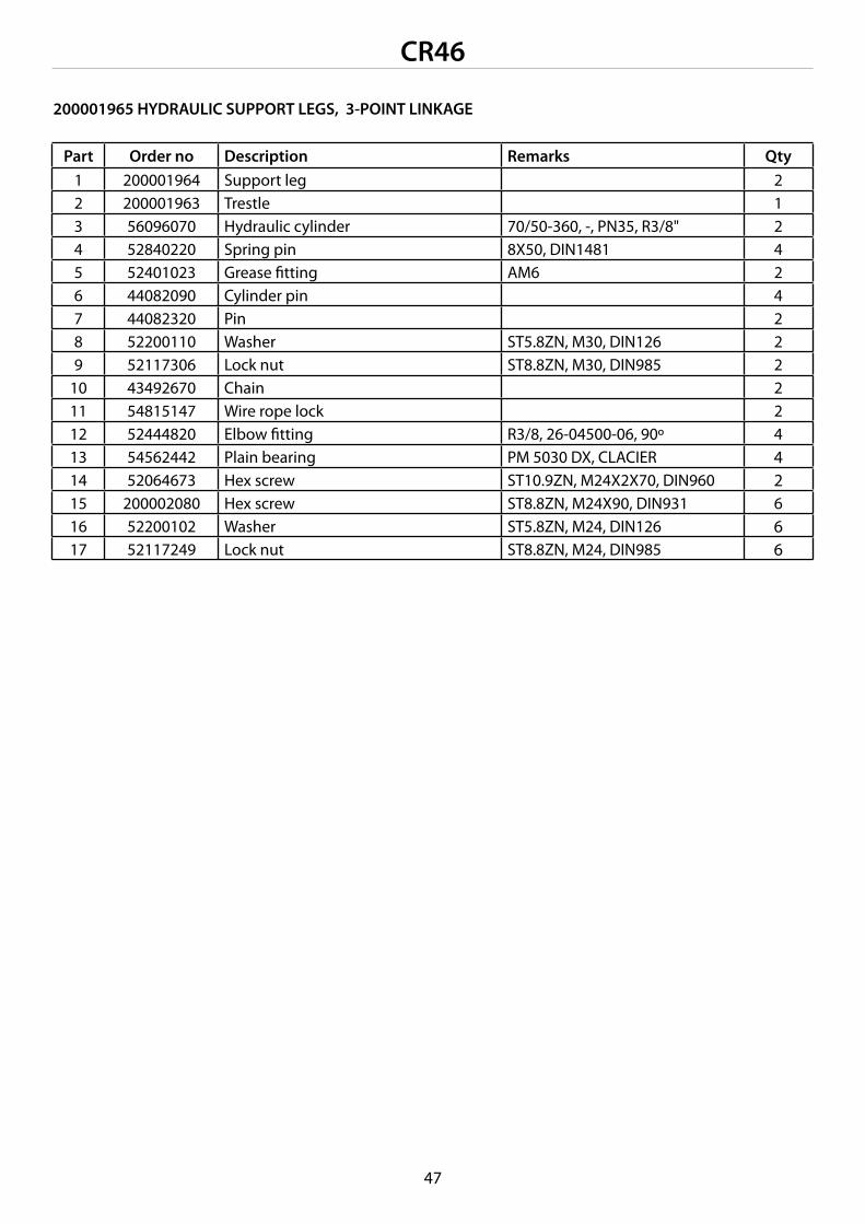
200001965 HYDRAULIC SUPPORT LEGS, 3-POINT LINKAGE 46
PRODUCT REGISTRATION FORM 50
CR46
4
WARNING SYMBOLS IN THIS MANUAL
• imminent danger which could cause serious personal injury or death
• danger which could cause personal injury
• conditions or misuse that could damage equipment or machinery
• reminders, such as for performing checks or carrying out maintenance or repair procedures
INTRODUCTION
This manual includes the information and maintenance instructions required for operating the machine in the optimal manner. Although you have experience in using this kind of machinery, read the operation and maintenance instructions carefully since they include information enabling efficient and safe operation. Regular maintenance is the best way to guarantee the efficient and economical performance of the machine.
Each and every operator must read, understand, and follow all safety instructions and procedures.
CUSTOMER FEEDBACK
We are happy to receive your opinions and suggestions for improvements by mail, fax or e-mail.All implemented suggestions for improvements will be rewarded.
WARNING!
!
CAUTION!
!
!DANGER!
CAUTION!
!
PRODUCT WARRANTY
Farmi provides a 12-months warranty on all Farmi products.Register on our home page (www.farmiforest.fi) under FeedBack (”Product Registration” form) within 30 days after the receipt of the product to get full product warranty and additional information on your product. If it is not possible for you to register via internet, please register as follows: Complete the registration form on the last pages of this manual and return it to us within 30 days after the receipt of the product.
CR46
5
Manufacturer:Farmi Forest Corporation Ahmolantie 6, FIN-74510 IISALMI, Finland
Person authorized to compile the technical documentation:Name: Matti BergAddress: Ahmolantie 6, FIN-74510 IISALMI, Finland
Commercial name:Farmi
Machine denomination:Hydraulic crane
Machine type:CR46
Machine series number:
Herewith, we declare that the machine brought into circulation conforms with the pertinent requirements of the Machinery Directive 2006/42/EC and the EMC Directive (directive relating to electromagnetic compatibility) 2004/108/EC.
The following harmonized standards have been applied for the conceptional design of the machine: EN ISO 12100, EN 12999, EN ISO 4413, EN60204-1, EN ISO 4254-1
Iisalmi 24.10.2016 (Place) (date)
Sami Jerkku
EC DECLARATION OF CONFORMITYOriginal declaration of conformity
CR46
6
GENERAL SAFETY INSTRUCTIONS
These safety instructions are meant for the owners of FARMI equipment, as well as those who operate, service or repair it.
The instructions help with:
• using the machine safely, appropriately and effec-tively.
• identifying, avoiding and preventing potentially dangerous situations.
The manufacturer supplies an instruction manual, which must always be available at the place of ope-ration of the machine. Each user must read the safety, maintenance and operating instructions before operating the machine, and comply with these instructions at all times.
Ensure that every operator of the machine is familiar with the content of the instruction manual and situation-specific safety instructions, and has been sui-tably trained before operating the machine.
The machine complies with technical requirements and applicable safety regulations. However, incorrect use, maintenance or repair of the machine may cause risks.
In addition to the instruction manual, remember to comply with regulations of the local occupational health and safety authorities, and with your country’s laws and decrees.
The manufacturer is not liable for damages caused by:
• incorrect, negligent or inappropriate use of the product.
• non-original spare parts.• normal wear and tear.• misuse caused by an untrained person’s
improper actions.• alterations made without the manufacturer’s
permission.
Written authorization must be requested from the manufacturer for any alterations to the machine.
STARTING
• Familiarize yourself thoroughly with the use, opera-tion and controls of the machine and its equipment before starting.
• Familiarize yourself with the capacities and limita-tions of the machine and its equipment.
• Do not use the machine unless you are completely familiar with its operation.
• Be aware of the machine’s danger zones.• During operation, prevent bystanders from entering
the danger zone.• Ensure that each operator has the necessary safety
equipment, such as a helmet, safety goggles, work safety boots and suitable protective clothing.
• Never wear loose clothing around moving parts. Protect long hair!
• Ensure that work is carried out according to the stipulations of applicable occupational health and safety legislation.
• Before starting up or using the machine, ensure that it cannot cause a risk to other people or property.
• Perform a safety check on the machine before eve-ry use. If you observe any faults or deficiencies, re-pair the machine immediately.
• Before operating the machine, ensure that there are no foreign articles in it.
• Place the machine on a hard, level surface for ope-ration. In the winter avoid working in slippery areas.
• Before mounting and using the machine, check the PTO drive shaft for correct condition and attachment.
• Never use a faulty or deficient machine.
CAUTION!
!
CAUTION!
!
CR46
7
TRANSPORT
• Before driving with the machine, ensure the safe mounting of the machine. Make sure that the journals are seating correctly and that the pins are tight. Check the tension of the lower link stabilizers.
• Before driving with the machine, make sure that the required lamps and reflectors as well as the slow moving vehicle sign are attached correctly. Moreover, the lamps should be checked for correct functioning.
• Before driving with the attached machine, make sure that the hydraulic unit of the machine is dep-ressurized (unless otherwise instructed in the ope-rating instructions).
• When driving on public roads, always observe the valid traffic regulations. The travel speed must be adapted to the specific conditions.
• When driving, please take into consideration the additional mass resulting from the machine’s weight. It may affect the reactions, the steerability and the braking function of the tractor.
• Please note that the machine rear sways when turning.
• Pay attention to the machine’s height near bridges or other height restricting objects.
• When backing off, the machine may obstruct the rear view. Exercise extreme caution. If necessary, ask a flagman to help you; he can indicate the required distances.
• It is prohibited for other people to ride on the ma-chine.
OPERATION
Many occupational accidents take place in abnormal circumstances. Therefore it is im-portant to take into account all the possible circumstances that may arise during operation of the machine.
• Depending on the machine’s type, it will have diverse safety devices and protectors. These are meant to protect the machine and its operator, and they must never be removed or altered. Never start up or use the machine without all the safety devices and protectors in place. Also check the uni-versal joint’s safety equipment and joins.
• Never insert any body part into the machine with the engine running.
• If any faults arise that may jeopardize occupational safety, turn off the machine.
• During operation, the machine’s operator is res-ponsible for safety in the whole work area. Work may not be carried out in the presence of any fac-tors that jeopardize occupational safety.
• Exercise extreme caution when hitching / unhit-ching the machine from a tractor/trailer.
The machine’s operator must have constant, unobstructed visibility of the work area. If this is not possible, the operator must work with an assistant.
• Look out for moving parts when the machine is in operation.
• Secure the machine against unauthorized and accidental operation (e.g. moving when parked) whenever it is left unattended.
• Never leave the machine running unattended.• Avoid causing fast, stroke-like loading.• Never exceed the given operating values.• All safety and warning signs on and in the machine
must be legible and intact.• The machine may not be operated by persons who
are unwell or under the influence of drugs or alco-hol.
MAINTENANCE
• The machine may only be serviced and repaired by professionals.
• Electrical and hydraulic faults may only be repaired by authorized professionals.
• In cases requiring welding, contact the manufac-turer.
• Turn off the tractor engine and disconnect the uni-versal joint before beginning service or maintenan-ce actions.
• Before any maintenance work, turn the main power switch of the tractor to OFF.
• Ensure that there is no pressure in the hydraulic system.
• Take out the key from the tractor’s ignition for the duration of the servicing or maintenance. Check that the power is off from the machine you are working on.
!DANGER!
CAUTION!
!
CR46
8
• When servicing the machine, place it on a level sur-face and ensure that it cannot be moved.
• Observe the service intervals and annual safety inspections.
• All spare parts and equipment must fulfill the manufacturer’s requirements. This can be guaran-teed by using original parts.
• Put all safety devices back into place immediately once servicing or maintenance is complete.
When lifting the machine, check that the lifting/hoisting equip-ment is in perfect working order. Check the weight of the machine before lifting it. Choose lifting trajectories so that they do not cause any danger.
Many countries have specific legislation on lifting, hois-ting cables and hoists. Always comply with local safety regulations.
OILS AND LUBRICATION
• Always use the oil types recommended by the manufacturer. Other types of oil may cause faults or improper operation of the equipment, which could lead to serious damage to people or property.
• Never mix different liquids or oils.• Always follow the manufacturer’s lubrication
instructions.• Use control equipment carefully until the hydraulic
oil has had time to reach its operating temperature.
SAFETY INSTRUCTIONS FOR HYDRAULIC CIRCUITS
1. Work on hydraulic equipment may only be carried out by professional hydraulic engineers.
2. Be cautious when using the equipment in cold con-ditions.
3. Check the machine for leaks. Do not use the machine if there is a leak from any system. Check all hydraulic hoses – particularly those which are bent during use – and replace any that are in poor con-dition or have leaks. Ensure that all joins are tight and that the lines are not damaged. Check that all protective caps and filler caps are closed properly. Check the hose sheathing for damage.
4. Check that all hose connectors, lengths and qualities comply with applicable requirements. When replacing or repairing hoses, use original parts or hoses and connectors recommended by the manufacturer. Check particularly that the pressure classes of the hoses and connectors are suitable to the operating pressure levels.
5. Check that all safety devices such as pressure relief valves, etc., are in place and work properly. Familiarize yourself with their use. Safety systems may never be bypassed.
6. Check the main hydraulic parts daily, and always after a fault. Replace any damaged parts imme-diately.
7. If a component is damaged, clean it before re- pairing it. Do not use solvents when cleaning parts.
8. Do not attempt to carry out repairs that you are not fully familiar with.
9. Never carry out repairs of the hydraulic circuit when the system is pressurized. When pressurized, the oil spray can penetrate the skin and cause mor-tal danger.
10. Never work below a device or component that is only being held up by hydraulics. Use separate sup-ports when carrying our maintenance or repairs. Do not disconnect cylinders or their valves until the machine is well supported.
11. Most hydraulic oils do not evaporate easily. Risk factors include hot oil, spills and oil mist (pressu-rized).
12. If oil gets into your eyes, rinse with plenty of water and contact a doctor.
13. Avoid prolonged or repeated contact with your skin.
14. If sprays or contact with the skin cannot be avoided, use protective gloves, goggles and clothing as necessary. Do not use oily clothing.
CAUTION!
!
CR46
9
15. Avoid discharging hydraulic oil into the environ- ment, as it can pollute waterways and the ground-water. If biodegradable oil is to be used, please contact the manufacturer beforehand and have the suitability of your equipment for the operation with biodegradable oil confirmed by him before such oil is used.
16. Store the oil in sealed containers provided by the manufacturer. Try to transfer the oil directly from its container into the tank.
17. If the oil must be passed through other containers, ensure that they are completely clean. Caps, fun-nels, sieves and filling holes must also be clean.
18. Never store oil outdoors, as water could condense in it.
19. Always dispose of oil in a suitable container, never into the environment!
CR46
10
Voltage rating, kV Minimum distance, mOverhead line Pendant line
below on side<1 2 2 0,5
1-45 2 3 1,5110 3 5 -220 4 5 -400 5 5 -
SAFETY INSTRUCTIONS FOR LOADERS
• Ensure the machine is properly supported during storage.
• Council of State Decision 856/1998 requires that loading crane operators be at least 18 years of age and have received sufficient instruction in its ope-ration. This applies in Finland.
• Before starting the machine, ensure that there are no bystanders within a radius of 20 meters.
• During operation, the vehicle must be positioned on sufficiently solid ground, in a properly stab-le position. The support legs must be used in all circumstances.
• Always put on the parking brake during loading.• Do not exceed the given load values.• Never stand beneath a hanging load.• Do not leave booms in raised position unattended!• The loader must not be used for lifting people.• When lifting, note that the booms sag slowly.• When working in the proximity of live wires, always
adhere to the given safety distances (cf. table).
• Take particular care when lifting heavy loads and turning the loader to the side.
• Never use the loader for towing.• Do not run the machine’s movements to their
extremes at full speed.• If the vehicle assembly falls over, do not jump out
of the vehicle.• If the booms sag down under excess loading, use
the shifting boom to shift the load closer to the column. Do not open the grapple.
• If the machine comes into contact with a power line, do the following:
• Call for assistance immediately and ensure that no one enters the danger zone.
• If you are outside the machine, do not touch any part of the machine.
• If you are inside the machine, leave it by JUMPING OUT. When you jump, make sure both feet touch the ground at the same time. Do not touch the vehicle or the ground with your hands after jumping out. Move at least 20 meters away from the vehicle by hopping on two feet.
The noise level from the engine should not exceed 70 dB. Check the engine noise and wear ear protection if it exceeds 70 dB.
9. Folding cylinder10. Extension cylinder11. Pendant + rotator12. Grapple13. Grapple cylinder14. Mounting rack + hydraulic support legs15. Support leg cylinder16. Control valve
TECHNICAL DATA
CR46
12
TECHNICAL DATA CR46Gross lifting torque, kNm 46Net lifting torque, kNm 37Max. reach, m 7Lifting capacity without equipment, kg 4 m 6,7 m
760420
Slewing torque, kNm 11,6Weight with equipment, kg 875Hydraulic support legs, weight, kg 295Recommended pump capacity, l/min 30-60Working pressure, bar 180Directional control valve, standard (accessory) On/Off ( HPC)Hydraulic support legs with 3-point linkage standard
CR46
13
1
65
4
3
2
STICKERS AND PLATES
These stickers and plates must be found on the crane. Replace missing stickers or plates immediately.
1. Machine plate CR46 (200002498)
2. Danger area 20 m (40146720)
3. Lifting capacity CR46 (200002556)
4. Minimum distance (40146730)
5. FARMI Smart (200002509)
6. Sticker CR46 (200002515)
CR46
14
INSTALLATION INSPECTION
Decisions 354/83 and 530/83 made by the Finnish Council of State stipulate that an installation inspection must be performed for each crane-vehicle assembly before use.
An inspection form can be found in this manual.
The person performing the inspection must be familiar with the crane’s construction and operation.
MOUNTING THE MULTI- AND DOUBLE-ACTING VALVES
The valve must be positioned or covered so that the levers cannot be used inadvertently.
Install the valve using the included bracket at the desired location, paying attention to the direction of the hoses and movement during loading and trans-ferring so that there is no risk of abrasion or clamping.
The label indicating the safe distance from live conductors must be clearly visible during operation.
Hoses in the operator’s cabin must be protected so that the user is not endangered by oil jets in the event of breakage.
The levers in the multi-lever valve can be moved to different positions if necessary. Detach the levers from the valve before moving them.
ASSEMBLY AND MOUNTING
Read these instruction before starting any assembly or moun-ting work. Improper mounting work can cause hazards during use of the crane. Mounting car-ried out in a manner other than
that specified in this manual can expose the user to danger and will void the manufacturer’s guarantee.
Check the stability of the crane-vehicle assembly by performing the necessary calculations. See “Determi-ning the stability”.
The mounting must be performed by the manufac-turer or a service center or person authorized by the manufacturer.
The strength class of the mounting bolts is 10.9. Use self-locking nuts, e.g., DIN985.
Put all screws into place. First tighten all screws in threa-ded holes to torque, and then all screws in unthreaded holes.
Retighten the bolts after the test run and the first day of use.
When mounting the crane on a foundation not delive-red by FARMI Forest, use the mounting plate shown in figure 1.In mounting, allow enough space for servicing and repairs.
CAUTION!
!
CAUTION!
!
CAUTION!
!
!DANGER!
Fig 1.
CR46
15
The person testing the crane must be qualified to use it.
1. Read the installation inspection report. If no installation inspection has been performed, do not use the crane.
2. Ensure that the control valve’s pressure line (P) has been connected properly and that the return (T) is unobstructed.
3. Check the hydraulic oil level.4. Familiarize yourself with the control valve’s
functions.5. Ensure that the hoses can move freely. Remove
any transport supports and ties.6. Ensure that there are no people or obstacles in
the operating area. The danger zone is 20 m.7. The crane must be tested on a level, firm base.
TESTING
1. Ensure that the control valve’s control levers are in the middle position.
2. Connect the oil flow to the crane. Let oil flow through the valve for a while.
3. Lower the support legs.4. Carefully drive the crane movements one by one
to their extreme positions and repeat this until the movements are smooth.
5. After testing the crane, inspect the joints and repair any leaks.
6. Check the mounting bolts of the crane and the fitting stand, and tighten them if necessary.
7. Check the hydraulic oil level, and top up the oil if necessary.
Be careful when bleeding air from the system. If you drive a cylinder to its extreme position at full force, the air pressure in the cylinder will damage the seals.
Be extremely careful when there is air in the cylinders.
CONNECTION TO THE HYDRAULIC SYSTEM
Before connecting the crane to the tractor’s hydraulic system, make sure that the oils are compatible. The cra-ne has been tested using ISO VG46S oil that meets the API SE, CD, and API GL-4 requirements.We recommend connecting the pressure hose to the single-acting hydraulic outlet and the return hose to the tank via the return filter. The filter’s intended flow rate is 80 l/min and the filtering density 25 µm abs.The crane can also be connected to the double-acting hydraulics outlet. If this is done, make sure that the lever of the double-acting valve controlling the flow is in the right position so that the pressure is directed to the pressure connection of the crane’s control valve. Check the operation of the double-acting outlet in the vehicle’s operating manual.
COMMISSIONING
Before using the crane, familiari-ze yourself with the operating and safety instructions.
INSPECTIONS BEFORE TESTING
Do not pressurize the hydraulic system before connecting the control valve’s 1/2” quick couplings to the vehicle’s hydraulic system.Connect the pressure hose (P) to the valve as indicated by the arrow and the return hose (T) to the vehicle as indicated by the arrow.
Do not pressurize the control valve’s return line (T) – this could cause the valve to break.Ensure that the 1/2” quick coup-ling are locked.
CAUTION!
!
CAUTION!
!
CAUTION!
!
!DANGER!
CR46
16
PRACTICE RUNS
• Drive through every movement with an unloaded crane, paying attention to the positions in which the crane can hit obstacles.
• Move the control levers smoothly and steadily, avoiding quick and jerky movements.
• Learn to use several functions simultaneously. This enables smooth, precise operation.
• Start off at a low engine speed in order to avoid sudden movements.
• When you have become accustomed to the crane’s movements, choose the appropriate engine speed so that operation is efficient but you still have the movements under control.
The lowest recommended operating temperature for the crane is -25oC.
Note that the hydraulic seals, hoses, and steel structures are prone to damage at low temperatures.When starting work at cold temperatures, first let the oil flow freely through the valve for a couple of minutes.
The maximum operating temperature for hydraulic oil is +75oC.
Use the support legs only to provide additional support for the vehicle.
When working on an inclined surface, do not load the crane with the full lifting torque, and be extremely careful.
When loading from uphill, note that the slewing movement may not be able to support the load but the pressure relief valves can be overloaded and the load can move down, causing a danger of the crane falling over.
Never move the boom to its extreme position at full speed!
Be careful when working near electric cables.Observe the safe distances.
When transferring the crane, support it against the trailer body or load.
DETACHING THE CRANE
Ensure that the ground under the crane is sufficiently hard and level.
Ensure that there are no extra people around and that no danger will be caused to others where the crane is to be stored. Pay special attention to the storage loca-tion of the control valve, ensuring that, e.g., it is out of the reach of children.
Always switch the pump off before removing the quick coup-ling between the crane and the vehicle.
When detaching the crane from the vehicle, make sure that there are no people in the immediate vicinity.
1. Lower the support legs to the desired height.2. Lower the booms as shown in fig. 2.3. Lower the crane using a hoist.4. Make sure that the crane cannot lean over. Fig. 2.5. Detach the crane from the vehicle.6. Detach and cover the control valve’s quick
couplings.
Fig. 2. Lowering the booms
CAUTION!
!
CAUTION!
!
CAUTION!
!
WARNING!
!
!DANGER!
CR46
17
STORAGE INSTRUCTIONS
1. Clean the crane and, if necessary, touch up any points where paint has peeled off.
2. Lubricate the crane thoroughly (see Lubricating Instructions).
3. Release the pressure from the cylinders.4. Protect the cylinder piston rods and exposed
parts of the control valve with grease.5. Store the crane in a sheltered area, away from
direct contact with the ground.6. When you start using the crane again, remove the
protective grease from the cylinder piston rods and the control valve.
MAINTENANCE
• Maintenance work must be carried out regularly to ensure safe and trouble-free operation.
• Always use the appropriate tools.• Determine the location of the defect.• Keep the disassembled sections, removed parts,
and the repair area protected from dirt.• Clean the parts using kerosene, never fuel oil.• Valve adjustments and repairs are to be performed
by dedicated service personnel.
SLEWING DEVICE
• See maintenance table.
BOOMS
• Keep the axial clearance in the joints as small as possible. Do not over-tighten.
REPLACING BEARINGS
• When installing bearing sleeves, use an appro- priate drift.
• Make sure that the new bearing’s grease hole meets the nipple.
• If the bearings have grease pockets, fill these with Vaseline.
CR46
18
PRESSURE MEASUREMENT
Always make the adjustments with the manometer in place.• The main pressure is measured from the measuring
point in the control valve’s inlet section.• Adjustments and inspections for each movement:
• Set the main pressure relief valve to 5 bar above the value set for the protective valve.
• Perform the movement, and check and adjust the pressure if necessary.
• Finish by adjusting the main pressure to the set value.
• Pressure measurements are to be performed at the normal operating temperature and at the normal flow rate.
• The free flow pressure can be read from the manometer when the flow of oil is directed through the valve.
REPAIR WELDING
If welding is required for modifying or repairing the crane, note the following:
• Have welding work always performed by qualified personnel; class C. Class B is only required for wel-ding joints which must withstand high stress.
• Remove paint and any oil from the location to be welded.
• Connect the ground terminal directly to the piece to be welded – there must be no joints in between.
• Use OK 48.00 or equivalent electrodes. The electrodes must be dry.
Using the appropriate hydraulic oils and lubricants is essential for the trouble-free operation of the machine.
CHANGING THE OIL
Change the oil according to the vehicle’s maintenance recommendations. The crane has been filled with ISO VG46S oil at the fac-tory.If the oil temperature does not exceed 70oC in the summer, winter oil can be used all year round.
When changing oil, make sure that the oil grade being used is compatible with the system and any oil remai-ning in it.
HYDRAULIC OIL REQUIREMENTS
The freezing point must be below -50oC.
The viscosity must not be lower than 1.5 Eo, +50oC for piston pumps and 2.5 Eo, + 50oC for gear pumps.
The hydraulic oil must contain the necessary additives for lubrication, rust protection, and defoaming.
Hydraulic oils intended for use in tractors are usually also suitable for use in hydraulic cranes.
OIL MAKE HYDRAULIC SYSTEM GREASE NIPPLES-10oC ...+30oC -25oC...-10oC
BP ENERGOL SHF 46 ENERGOL SHF 32,22 ENERGREASE LS-EP2, L21MESSO UNIVIS N46 UNIVIS N 32,22 BEACON EP2,
MULTIPURPOSE GR MOLYMOBIL DTE 16 DTE 15,13 MOBILUX EP 2
TROUBLE POSSIBLE CAUSE REMEDYCRANES WORKING MOVEMENTS SLOW
PUMP IS TOO SLOW CHECK PUMPS ROTATING SPEEDFAULTY PUMP CHANGE OR GET THE PUMP FIXEDLEAKS OR OBSTRUCTIONS IN OIL LINES
INSPECT OIL LINES
OIL TOO THICK CHANGE TO A THINNER (CORRECT) OIL GRADE
CRANES DESCENDING MOVEMENTS SLOW
OBSTRUCTIONS IN THE OIL LINES CHECK THE LINES AND THE CHOKESCLOGGED-UP (RETURN) FILTER CLEAN OR RENEW FILTEROIL TOO THICK CHANGE TO A THINNER (CORRECT) OIL
GRADECRANES MOVEMENTS TOO FAST
ROTATION SPEED TOO HIGH OR PUMP TOO BIG
CHOOSE A CORRECT SPEED OF ROTATION AND CORRECT PUMP SIZE
INCORRECT OPERATION LEARN TO OPEN THE CONTROL VALVE TO A SUITABLE DEGREE
CRANES WORKING MOVEMENTS POWERLESS
NOT ENOUGH OIL ADD OIL (AIR BLEEDING)FAULTY PUMP CHANGE OR GET THE PUMP FIXEDFAULTY RELIEF VALVE OR SHOCK VALVES
CHANGE THE RELIEF VALVE OR SHOCK VALVES
FAULTY CONTROL VALVE CHANGE OR GET THE VALVE FIXEDFAULTY CYLINDERS OR SEALS CHECK THE CYLINDERS AND CHANGE THE
SEALSCRANE MOVEMENTS ARE JERKY
AIR IN HYDRAULIC SYSTEM CHECK OIL LEVEL, BLEED AIR FROM SYSTEMNOT ENOUGH OIL CHECK THERE ARE NO OBSTRUCTIONS OR
LEAKS ON THE INLET SIDE, ADD OIL
FAULTY PUMP CHECK THE PUMP AND GET IT FIXEDBOOMS DESCEND BY THEMSELVES
FAULTY CONTROL VALVE INSPECT THE CONTROL VALVE AND GET IT FIXED
FAULTY CYLINDERS OR HOSESFAULTY SHOCK VALVE
FIX THE LEAKAGE POINT. CHECK CYLINDERS AND SEALS,CHECK, CLEAN, ADJUST
CHECK SCREWS TIGHTENING TORQUE (CON-TACT THE MANUFACTURER),CHANGE A NEW BLOCK WITH SPINDLES
TROUBLE SHOOTING
CR46
22
You can use the example for calculating the stand stability for any tractor by measuring ”K” and ”H” from the tractor. With these measures you can calculate ”C”.
K = Distance between the tractors rear shaft and the cranes pivot pointH = Tractors wheelbase
See the tractors manual for rear axle weight M3, “n” value must be more than 1.
TESTING THE STABILITY
The formulas and examples included in these instruc-tions are based on the SFS 4677 standard.During the test, the vehicle is in normal working con-dition without load, tilted 5o to the side. The ground must withstand the maximum load applied by the wheels or the other points of support.
The test is performed at the maximum reach with 10% overload. All normal crane functions are performed, but cautiously. The vehicle’s 5o inclination is achieved by putting a suitable riser under one of the rear wheels. Its height can be calculated as follows: h = riser height needed z =vehicle width from wheel center to wheel center h = 0.087 x z Example: z =180 cm h = 0.0887 x 180 cm = 16 cm
The vehicle is considered stable if no more than one point of support rises off the ground during the test. Increased stability when loading it from the side can be achieved by lengthening the track and/or adding rear axle load by using, for example, wheel weights.
DETERMINING THE STAND-STABILITY BY CALCULATION
The crane is considered stable when the stability ratio ”n” calculated from formula below is equal or larger than 1.
EXAMPLE 1
A1 = Normal distance from cranes turning center to overturning edge.B1 = Normal distance from booms end (load) to over-turning edge.C1 = Distance from vehicles rear axles center and overturning edge.E1 = Normal distance from booms point of support to overturning edge.G = Maximum load at distance A + BN = Cranes weight without boomsP = Booms weight (centroid)M2 = Rear axle weight without load n1 = Stability factor
Formula C =H x AK + H
EXAMPLE 2
A2 = Normal distance from cranes turning center to overturning edge.B2 = Normal distance from booms end (load) to over-turning edge.C2 = Distance from vehicles rear axles center and overturning edge.E2 = Normal distance from booms point of support to overturning edge.G = Maximum load at distance A + BN = Cranes weight without boomsP = Booms weight (centroid)M3 = Rear axle weight without load n2 = Stability factor
CR46
23
A1
M2
E1B1
C1
G
N
P
K H
M3
N C2E2
PB2
A2
G
EXAMPLE 1tractor + FARMI 100 + CR46
Formula n =N x A1+ M2 x C1
G x B1 + P x E1
N = 870 kg B1 = 480 cm C1= 90 cm
A1 = 220 cm P = 525 kg M2 = 1000 kg
G = 420 kg E1 = 100 cm
n1 =870 x 220 + 1000 x 90
=1,107420 x 480 + 525 x 100
EXAMPLE 2tractor Valtra T190 + CR46
Formula n =N x A2 + M3 x C2
G x B2 + P x E2
N = 520 kg B2 = 560 cm C2= 120 cm
A2 = 140 cm P = 525 kg M3 = 2190 kg
G = 420 kg E2 = 180 cm
n2 =520 x 140 + 2190 x 120
=1,018420 x 560 + 525 x 180
CR46
24
FUNCTION MULTI-LEVER VALVEMAIN PRESSURE RELIEF VALVE
Fig 4. Modifying the valve for closed center system
HYDRAULICS
CONNECTION TO THE CLOSED CENTER SYSTEM, ON / OFF, 80 l
1. Replace the R1/2” plug on the T fitting by a R1/2” double nipple. Connect the tank hose here.2. Plug this hole for the tank hose with R1/4” and R1/2” plugs.3. Tighten the main relief valve by ¾ turn so that its pressure is at least 5-10 bar higher than that of the tractor
New tank hose:Replace the R1/2” plug by a R1/2” double nipple.
Plug the original hole for the tank hose with a R1/4” taper plug and a R1/2” plug.
CR46
26
1 2 3 4 5 6 7 8
1
8
76 54 3
2
1
2
7
8
CONNECTING THE ON/OFF VALVE (60 l)
FOLDING
ROTATOR + GRAPPLE
EXTENSION
LIFTING
SLEWING
SUPPORT LEG, LEFT
SUPPORT LEG, RIGHT
RETURN (T)PRESSURE (P)
out in closed open
CR46
27
INSTALLATION INSPECTION RECORD
ITEM UNDER INSPECTION Notes F R1. Before installation; 3-point liftstate of lifting arm state of pusher arm locking of tractive resistance sensorgaskets and cleanness of hydraulic connections2. Before test drivecheck state of machine, load and operating platesstick minimum distance warning label e.g. to valve connector or rear windowcheck sizes and locking of loader’s mounting pinscheck that the hydraulic hoses are connected correctly check that fast couplings are securely in placecheck that valve shafts move smoothlycheck the amount of hydraulic oil in the tractorcheck valve table attachment check shielding of hoses in the cabin and shielding of leverscheck tightness of loader fastening screws (cf. installation manual)3. During test drivecylinder bleedingdetermining stand stabilitytest use with allowable load (cf. loading table)loader/cabin at various hoist positionsloader/cabin at various boom positionshose friction4. After test drivesagging of booms, max. range 15 cm/mincheck amount of oil with cylinders broken inoil leaks; tighten joins if necessary
CRANE TYPE FARMI CHASSIS: modelSERIAL NO. make, modelYEAR OF MANUFACTURE
Load test according to SFS 4261
date: performed by:
F = faultless R = needs repair
CR46
28
ANNUAL INSPECTION RECORD
ITEM UNDER INSPECTION ANNUAL INSPECTION
F R NOTES
CLEANLINESS OF LIFTING BOOMWELDED JOINTS OF LIFTING BOOMWELDED JOINTS OF FOLDING BOOMSWELDED JOINTS OF COLUMNFASTENING OF ROTATORSTATE OF BRACKETSBACKLASH OF ROTATING DEVICESTATE OF SWIVEL AXIS BEARINGSSTATE OF LIFTING BOOM BEARINGSSTATE OF FOLDING BOOM BEARINGSSTATE OF JOINT PINSLOCKING OF JOINT PINS STATE OF CONTROLSSTATE OF CYLINDERSSTATE OF CYLINDER GASKETSSTATE OF PISTON RODS STATE OF HYDRAULIC HOSESSTATE OF HYDRAULIC HOSE STATE OF HYDRAULIC CONNECTORSPROTECTION OF REGULATING VALVE LEVERS TIGHTNESS OF LOADER’S FASTENING OPERATION, MAINTENANCE AND INSPECTION MANUAL STATE OF SAFETY DISTANCE TABLE STATE OF LOAD SIGNSTATE OF MACHINE PLATEHAS INSTALLATION INSPECTION BEEN CARRIED OUT?PRESSURE RELIEF VALVE _______ barPROTECTION VALVES _______ barSTATE OF STRUCTURES AFTER MAX. ALLOWABLE TEST LOADSAGGING OF BOOMS, MAX. RANGE OF 60 cmSTATE OF SLIDE PLATES, MAX. GAP OF 8 mm
F = faultless R = needs repair
Inspector: Date and place: Notes:
CR46
29
CR46
30
1
10
9
8
7
6
5
4
3
2
11
20
19 18
17
16
1514
13
12
21
2827
23
22
4
4
56
7
810
1213
14
14
14
14
15
15
15
15
18
19
1818 19
23
200001774 CR46
CR46
31
200001774 CR46
Part Order no Description Remarks Qty1 13465710 Slewing device 12 200001637 Lifting boom 13 200001773 Folding boom 14 33460520 Joint pin 45 43465260 Joint arm 26 43465270 Joint arm 27 54566000 Plain bearing 28 52401015 Grease fitting AR1/8 29 43465320 Joint pin 1
Part Order no Description Remarks Qty1 200002615 Hose cover 12 200002996 Top cover 13 200002997 Repair kit for axle, bearing included 14 200002998 Plate kit all wings included 15 200002999 Spring all springs included 16 200003000 Chamber 17 200003001 Seal kit all seal included 18 200003002 Lid 19 200003163 Extension coupling G3/8" 2
10 52091535 Hex socket cap screw M10x90 12,9 1011 200003165 Hex socket cap screw ST12.9 BLACK, M10X30, DIN 912 412 52200045 Washer ST5.8ZN, M10, DIN125 413 52390556 Usit seal ring R3/8" 814 52432028 Double fitting R3/8 415 52450152 Straight thread connector 216 200003164 Grease fitting M8x1,25 1
CR46
40
1
3
2
Part Order no Description Remarks Qty1 200003014 Frame 12 200003015 Upper pin kit 13 200003016 Lower pin kit 1
200001717 CROSS LINK, WITHOUT BRAKE
CR46
41
3
1
2
5
4
Part Order no Description Remarks Qty1 200003014 Frame 12 200003015 Upper pin kit 13 200003017 Lower pin kit 14 200003018 Brake disc kit 5 200003019 Spring kit
200001712 CROSS LINK, WITH BRAKE
CR46
42
3
1
2
5
4
Part Order no Description Remarks Qty1 200003014 Frame 12 200003020 Upper pin kit 13 200003017 Lower pin kit 14 200003018 Brake disc kit 5 200003019 Spring kit
200001715 CROSS LINK, WITH DUAL BRAKE
CR46
43
CR46
44
6
5
4
3
2
1.1
1.10
1.11
1.12
1.13
1.9
1.8
1.7
1.2
1.6
1.3
1.4
1.5
1.5
1.5
1.5
1.9
1.9
1.10
1.10
1.101.10
1.11
1.111.111.11
1.11
1.11
4
200002801 TIMBER GRAPPLE PTK021S / CR300
CR46
45
Part Order no Description Remarks Qty1 23595050 Timber grapple 1
Farmi Forest Oy grants a 12-month warranty on all of its products, covering material and manufacturing faults. The warranty comes into effect on the product’s delivery date.
The manufacturer is not liable for damages caused by:
• misuse of the product• alterations or repairs made without the manufacturer’s permission• insufficient maintenance• non-original parts
The warranty does not cover wearing parts.
Send faulty parts, carriage paid, to the manufacturer for inspection. Repairs will be conducted by Farmi Forest Oy or an authorized expert. The warranty is valid only if the bottom part of this page is filled in and returned to the manufacturer within 30 days of receipt of the product.By returning the warranty certificate, you confirm that you have read and understood the instruction manual that came with the product.