67 E 3.701.12/03.12 Hydraulic Dampers 1. HYDRAULIC DAMPERS 1.1. DESCRIPTION 1.1.1 Mode of operation The pressure fluctuations occurring in hydraulic systems can be cyclical or one- off problems due to: z flow rate fluctuations from displacement pumps z actuation of shut-off and control valves with short opening and closing times z switching pumps on and off z sudden linking of spaces with different pressure levels. HYDAC hydraulic dampers are particularly suitable for damping such pressure fluctuations. Selecting the most suitable hydraulic damper for each system ensures that z vibrations caused by pipes, valves, couplings etc are minimised and subsequent pipe and valve damage is prevented z measuring instruments are protected and their performance is no longer impaired z the noise level in hydraulic systems is reduced z the performance of machine tools is improved z interconnection of several pumps in one line is possible z an increase in pump rpm and feed pressure is possible z the maintenance and servicing costs can be reduced z the service life of the system is increased. 1.2. APPLICATION 1.2.1 Pulsation damping TYPE SB...P / SBO...P without damper Pressure Time with accumulator (standard connection bladder accumulator) Pressure Time with accumulator as pulsation damper Pressure Time General The HYDAC pulsation damper z prevents pipe breaks caused by material fatigue, pipe oscillations and irregular flow rates, z protects valves, control devices and other instruments, z improves noise level damping. Applications The pulsation damper is particularly suitable for: hydraulic systems, displacement pumps of all types, sensitive measurement and control instruments and manifolds in process circuits in the chemical industry. Mode of operation The pulsation damper has two fluid connections and can therefore be fitted directly inline. The flow is directed straight at the bladder or diaphragm by diverting it in the fluid valve. This causes direct contact of the flow with the bladder or diaphragm which, in an almost inertialess operation, balances the flow rate fluctuations via the gas volume. It particularly compensates for higher frequency pressure oscillations. The pre- charge pressure is adjusted to individual operating conditions Construction The HYDAC pulsation damper consists of: z the welded or forged pressure vessel in carbon steel; available with internal coating or in stainless steel for chemically aggressive fluids; z the special fluid valve with inline connection, which guides the flow into the vessel (threaded or flange connection); z the bladder or diaphragm in various elastomers as shown under 1.4.1. Installation As close as possible to the pulsation source. Mounting position preferably vertical (gas valve pointing upwards).
Transcript
67
E 3.
701.
12/0
3.12
Hydraulic Dampers
1. Hydraulic dampers1.1. DESCRIPTION1.1.1 mode of operationThe pressure fluctuations occurring in hydraulic systems can be cyclical or one-off problems due to:
z flow rate fluctuations from displacement pumps z actuation of shut-off and control valves with short opening and closing times z switching pumps on and off z sudden linking of spaces with different pressure levels.
HYDAC hydraulic dampers are particularly suitable for damping such pressure fluctuations.Selecting the most suitable hydraulic damper for each system ensures that
z vibrations caused by pipes, valves, couplings etc are minimised and subsequent pipe and valve damage is prevented zmeasuring instruments are protected and their performance is no longer impaired z the noise level in hydraulic systems is reduced z the performance of machine tools is improved z interconnection of several pumps in one line is possible z an increase in pump rpm and feed pressure is possible z the maintenance and servicing costs can be reduced z the service life of the system is increased.
1.2. APPlICATION1.2.1 pulsation damping
Type sB...p / sBO...p
without damper
Pre
ssur
e
Time
with accumulator (standard connection bladder accumulator)
Pre
ssur
e
Time
with accumulator as pulsation damper
Pre
ssur
e
Time
GeneralThe HYDAC pulsation damper
z prevents pipe breaks caused by material fatigue, pipe oscillations and irregular flow rates, z protects valves, control devices and other instruments, z improves noise level damping.
applicationsThe pulsation damper is particularly suitable for: hydraulic systems, displacement pumps of all types, sensitive measurement and control instruments and manifolds in process circuits in the chemical industry.
mode of operationThe pulsation damper has two fluid connections and can therefore be fitted directly inline.The flow is directed straight at the bladder or diaphragm by diverting it in the fluid valve. This causes direct contact of the flow with the bladder or diaphragm which, in an almost inertialess operation, balances the flow rate fluctuations via the gas volume. It particularly compensates for higher frequency pressure oscillations. The pre-charge pressure is adjusted to individual operating conditionsconstructionThe HYDAC pulsation damper consists of:
z the welded or forged pressure vessel in carbon steel; available with internal coating or in stainless steel for chemically aggressive fluids; z the special fluid valve with inline connection, which guides the flow into the vessel (threaded or flange connection); z the bladder or diaphragm in various elastomers as shown under 1.4.1.
installationAs close as possible to the pulsation source. Mounting position preferably vertical (gas valve pointing upwards).
68
E 3.
701.
12/0
3.12
1.2.2 Suctionflowstabiliser Type sB...s
GeneralThe HYDAC suction flow stabiliser
z improves the NPSH value of the system; z prevents cavitation of the pump; z prevents pipe oscillations.
applicationsMain application areas are piston and diaphragm pumps in public utility plants, reactor construction and the chemical industry.mode of operationTrouble-free pump operation is only possible if no cavitation occurs in the pump suction and pipe oscillations are prevented.A relatively high fluid volume in the suction flow stabiliser in relation to the displacement volume of the pump reduces the acceleration effects of the fluid column in the suction line. Also an air separation is achieved due to the extremely low flow rate in the suction flow stabiliser and the deflection on a baffle. By adjusting the charging pressure of the bladder to the operating conditions, the best possible pulsation damping is achieved.constructionThe HYDAC suction flow stabiliser consists of a welded vessel in steel or stainless steel. Inlet and outlet are on opposite sides and are separated by a baffle. The upper part houses the encapsulated bladder. In addition, there is a vent screw in the cover plate and a drainage facility on the bottom.installationAs close as possible to the suction inlet of the pump. Mounting position vertical (gas valve pointing upwards).
without damper
Pre
ssur
e
Time
Pre
ssur
e
with accumulator (standard bladder accumulator)
Time
withaccumulatorassuctionflowstabiliser
Pre
ssur
e
Time
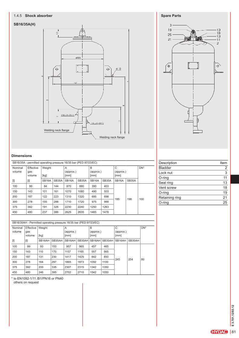
1.2.3 shock absorber Type sB...a
GeneralThe HYDAC shock absorber
z reduces pressure shocks; z protects pipelines and valves from being destroyed.
applicationsThe accumulators are particularly suitable for use in pipelines with quick-acting valves or flaps and whilst pumps are being switched on and off.They are also suitable for energy storage in low pressure applications.mode of operationSudden changes in pipeline flow, such as those caused by pump failure or the closing or opening of valves, can cause pressures which are many times higher than the normal values.The shock absorber prevents this by converting potential into kinetic energy and vice versa. This prevents pressure shocks and protects pipelines, valves, control instruments and other devices from destruction.constructionThe HYDAC shock absorber consists of:
z the welded pressure vessel in carbon steel with or without corrosion protection or in stainless steel; z the connection including perforated disc which prevents the flexible bladder from extruding from the vessel, and the flange; z the bladder in various elastomer qualities as shown under point 1.4.1 with built-in gas valve, which is used for charging pressure p0 and for possible monitoring activities.
special modelShock absorbers can also be in the form of diaphragm or piston accumulators. Available on request.installationAs close as possible to the source of the erratic condition. Mounting position vertical (gas valve pointing upwards).
On the suction and pressure side of piston pumps almost identical conditions occur regarding irregularity of the flow rate. Therefore the same formulae for determining the effective gas volume are used for calculating the damper size. That in the end two totally different damper types are used is due to the different acceleration and pressure ratios on the two sides.Not only is the gas volume V0 a decisive factor but also the connection size of the pump has to be taken into account when selecting the pulsation damper. In order to avoid additional variations in cross-section which represent reflection points for vibrations, and also to keep pressure drops to a reasonable level, the connection cross-section of the damper must be the same as the pipeline.The gas volume V0 of the damper is determined with the aid of the formula for adiabatic changes of state.By giving the residual pulsation or the gas volume, the damper size can be calculated with the aid of the HYDAC software asp (accumulator simulation program). The results can then be printed out or the data files can be stored in ASP format.The ASP-program is available free of charge via our website www.hydac.com or via E-Mail to [email protected].
suction side
V0 V0
designations:DV = fluctuating fluid volume [l] DV = m qq = stroke volume [l]
z = no. of compressions / effective cylinders per revolutionx = residual pulsation [± %]κ = isentropic exponentΦ = pressure ratio of pre-charge pressure to operating pressure [0.6 ... 0.9]
calculation exampleGiven parameters:Single-acting 3-piston pump Piston diameter: 70 mm Piston stroke: 100 mm Motor speed: 370 min-1 Output: 427 l/min Operating temperature: 20 °C Operating pressure - Outlet: 200 bar - Inlet: 4 bar
required:a) Suction flow stabiliser for a residual
pulsation of ± 2.5%b) Pulsation damper for a residual
pulsation of ± 0.5%
solution:a) Determining the required suction flow
stabiliser
V0 = 0.54 lselected: SB16S-25 with 1 l gas volume
b) Determining the required pulsation damper
V0 = 3.2 lselected: SB330P-4
isentropic exponent κ dependent on pressure and temperature:
VV
x x
0 1 1
1100
1100
=
−−
+
Δ
Φ Φκ κ
V0
2
11 4
11 4
0.035•0 74
10
0 6
12 5100
0 6
12 5100
=
−−
+
• .• .
..
..
..
π
VV
x x
0 1 1
1100
1100
=
−−
+
Δ
Φ Φκ κ
V0
2
12 0
12 0
0.035•0 74
10
0 7
10 5100
0 7
10 5100
=
−−
+
• .• .
..
..
..
π
71
E 3.
701.
12/0
3.12
determining the required damper sizeThe accumulator must absorb the kinetic energy of the fluid by converting it into potential energy within the pre-determined pressure range. The change of state of the gas is adiabatic in this case
m (kg) = weight of fluid in the pipelinev (m/s) = velocity of the fluidp1 (bar) = zero head of the pumpp2 (bar) = permitted operating pressure p0 (bar) = pre-charge pressure
A special calculation program to analyse the pressure curve is available for sizing during pump failure or start-up and for manifolds.
1.3.2 shock absorberPressure shock produced when a valve is closed without a hydraulic accumulator
Simplified pressure shock calculation for the closing of a valve.estimate of Joukowsky's max. occurring pressure shockDp(N/m²) = ρ • a • Dv ρ (kg/m³) = fluid density Dv = v - v1Dv = change of fluid velocity v (m/s) = fluid velocity before the change in its condition v1 (m/s) = fluid velocity after the change in its condition a (m/s) = propagation velocity of pressure wave
a (m/s) = 11
ρ ••D
E e+
K K (N/m²) = compression modulus of the fluid E (N/m²) = modulus of elasticity of pipeline D (mm) = internal diameter of pipeline e (mm) = wall thickness of the pipeline
The pressure wave runs to the other end of the pipeline and will reach the valve again after time t (reflection time), whereby:
t (s) =2 • L
aL (m) = length of the pipelineT (s) = effective operating time
(closing) of the valveIf T < t then:pmax = p1 + DpIf T > t then:
pmax = p1 + ρ • a • Dv •tT
v = v max
v < v max
PRESSURE SHOCKP = maximum
v = 0
v = 0
v = 0
Vm v
ppp
pp0
2
12
1
11
2
1
0
1
0 4
2 1 10
=
−−
• • .
• • •
•κ
κ
72
E 3.
701.
12/0
3.12
solution:Determination of reflection time:
* since T < t the max. pressure surge occurs and the formula as shown in Point 1.3.2. must be used.
Dp = ρ • a • DvDp = 980 • 1120 •(2.45-0) •10-5
= 26.89 barpmax = p1 + Dp
pmax = 6 + 26.89 = 32.89 bar
Determining the required gas volume:p0 ≤ 0.9 • pmin
p0 ≤ 0.9 • 5 = 4.5 bar
with
selected:4 off shock absorbers SB 35AH-450.
calculation exampleRapid closing of a shut-off valve in a re-fuelling line.Given parameters:Length of the pipeline L: 2000 mNW of pipeline D: 250 mmWall thickness of pipeline e: 6.3 mmMaterial of pipeline: SteelFlow rate Q: 432 m³/h = 0.12 m³/sDensity of medium ρ: 980 kg/m³Zero head of pump p1: 6 barMin. operating pressure pmin: 4 barEffective closing time of the valve T: 1.5 s (approx. 20% of total closing time)Operating temperature: 20 °CCompression modulus of the fluid K: 1.62 × 10⁹ N/m²Elasticity modulus (steel) E: 2.04 × 10¹¹ N/m²
required:Size of the required shock absorber, when the max. pressure (p2) must not exceed 10 bar.
• • •
• • •
m V D L= =• • • •ρπ
ρ4
2
V0
22
11
1 4 2
11 44
1641 l
0 25 2000 980 2 45 0 4
2 7 117 1 10
74 5
=
V0 =
−−
π• . • • • . • .
•.
.
.
Vm v
ppp
pp0
2
12
1
11
2
1
0
1
0 4
2 1 10
=
−−
• • .•
κ
κ
a =
+
1
980 1162 10
2502 04 10 6 39 11•
. • . • • .
tL
as= = =
2 2 20001120
3 575• •
. *
a m/s=1120
11
ρ ••D
E e+
a =
K
v = =012
0 25 42 45 m/s
2
.. •
.π
vQA
=
73
E 3.
701.
12/0
3.12
1.4. TECHNICAL DATA1.4.1 mOdel cOde (also order example)
seriesSB... = with bladder SBO... = with diaphragm
Type A = shock absorber AH = high flow shock absorber P = pulsation damper PH = high flow pulsation damper S = suction flow stabiliser
Nominal volume [i]
Fluid connection A = threaded connection E = threaded connection for welded construction (diaphragm accumulators only) F = flange 4)
Type code 1 = standard model (not for threaded construction) 2 = back-up model 1) 6 = standard model for thread-type diaphragm accumulators of the type SBO...P-...A6
material code 2) depends on operating medium Standard model = 112 for mineral oils
connction Al = ISO 228 (BSP), standard connection Bl = DlN 13 to ISO 965/1 (metric) 4) Cl = ANSI B1.1 (UNF thread,sealing to SAE standard) 4) Dl = ANSI B1.20 (NPT thread) 4)
SBO250P-0.075E1 and for SBO210P-0.16E1: AK = ISO 228 (BSP), standard connection
zzz
1) Not available for all models 2) Not all combinations are possible 3) When ordering spare bladder, please state diameter of the smaller shell port 4) Please give full details when ordering
74
E 3.
701.
12/0
3.12
1.4.2 GeneralOperating pressureSee tables (may differ from nominal pressure for foreign test certificates).Nominal volumesSee tableseffective gas volumeSee tables, based on nominal dimensions. This differs slightly from the nominal volume and must be used when calculating the usable volume.On the diaphragm accumulator, the effective gas volume corresponds to the nominal volume.
usable volumeVolume of fluid which is available between the operating pressures p2 and p1.FluidsMineral oils, hydraulic oils, non-flam fluids, water, emulsions, fuels. Others on request.Gas chargeHydraulic accumulators must only be charged with nitrogen. Never use other gases. risK OF eXplOsiON!When supplied, the accumulator is only pre-charged for storage purposes. Higher pre-charge pressures are possible by arrangement.
permitted operating temperature-10 °C ... +80 °C 263 K ... 353 K with material code 112. Other media on request.permitted pressure ratioRatio of maximum operating pressure p2 to gas pre-charge pressure p0.See catalogue section:
zAccumulators No. 3.000
General safety instructionsOn no account must any welding, soldering or mechanical work be carried out on the accumulator shell.After the hydraulic line has been connected it must be completely vented. Work on systems with hydraulic dampers (repairs, connecting pressure gauges etc) must only be carried out once the pressure and the fluid have been released.
* Certification to PED 97/23/EC 1) M56x4, high pressure connection DN 16, others on request 2) Standard connection code = AI, others on request 3) Special model, on request
sB330/550p(pH)-... sB800p-... sB1000p-...
Nominal volume [l]
Max. operating pressure* [bar]
Effective gas volume [l]
Weight [kg]
A [mm]
B [mm]
Ø D [mm]
E [mm]
H [mm]
J 2) thread ISO 228
Series
1 330
1.0 11 365 80 118
120 57
G 1 1/4
SB330P
550 13 384 70 121 53 SB550P
1.5 800 3)
1.3 36 346 – 160 – 55 SB800P
1000 3) 94 414 – 215 – 49 1) SB1000P
2.5 330 2.4 16 570 80 118
120
57
G 1 1/4
SB330P
550 2.5 20 589 70 121 53 SB550P
4 330 3.7 18 455 80
171 57 SB330P
26 491 100 150 85 G 1 1/2 SB330PH
5 550 4.9 26 917 70 121120
53G 1 1/4
SB550P
6
330
5.7 20 559 80
171 57 SB330P
28 593100
150
85 G 1 1/2SB330PH
10 9.3 40 620
229
SB330P
50 652 130x140 100 SAE2"-6000 PSI SB330PH
13
330
12.0 48 712100 85 G 1 1/2
SB330P
20 18.4 70 920 SB330P
80 952 130x140 100 SAE2"-6000 PSI SB330PH
24
330
23.6 82 986100 85 G 1 1/2
SB330P
32 33.9100 1445 SB330P
110 1475 130x140 100 SAE2"-6000 PSI SB330PH
76
E 3.
701.
12/0
3.12
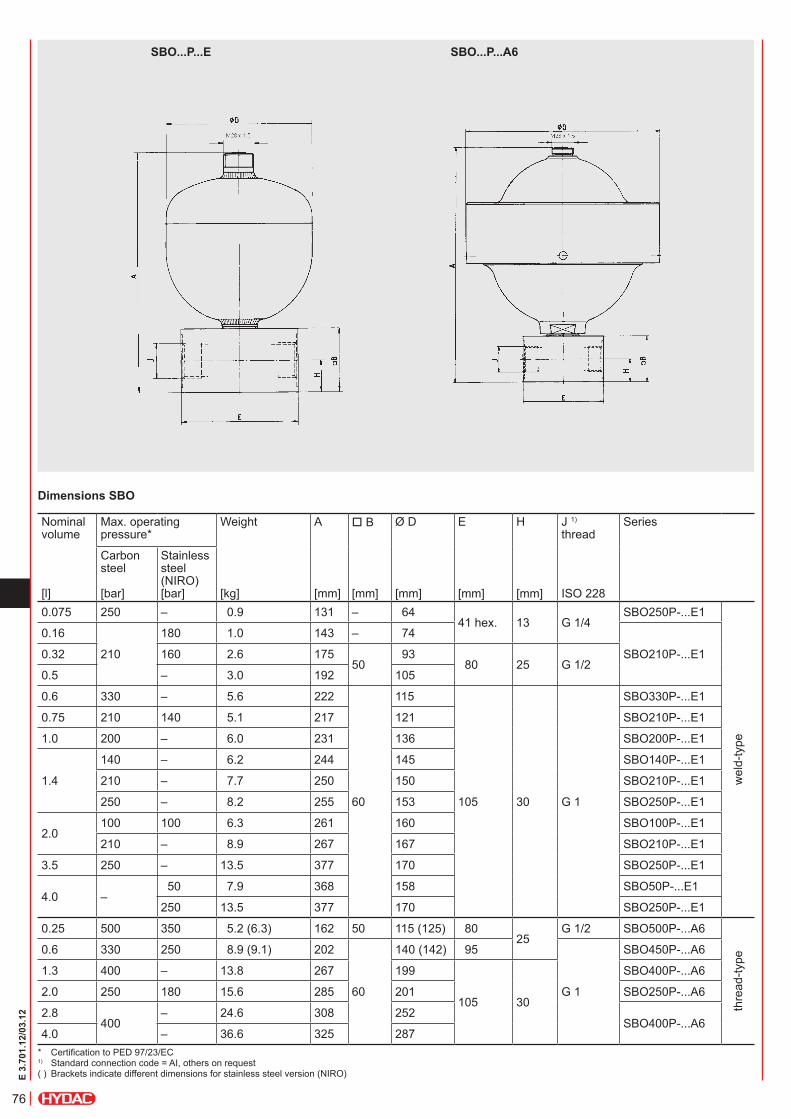
dimensions sBO
sBO...p...e sBO...p...a6
* Certification to PED 97/23/EC 1) Standard connection code = AI, others on request ( ) Brackets indicate different dimensions for stainless steel version (NIRO)
Nominal volume
Max. operating pressure*
Weight A B Ø D E H J 1) thread
Series
[l]
Carbon steel [bar]
Stainless steel (NIRO) [bar]
[kg]
[mm]
[mm]
[mm]
[mm]
[mm]
ISO 228
0.075 250 – 0.9 131 – 6441 hex. 13 G 1/4
SBO250P-...E1
wel
d-ty
pe
0.16
210
180 1.0 143 – 74
SBO210P-...E10.32 160 2.6 17550
93 80 25 G 1/2
0.5 – 3.0 192 105
0.6 330 – 5.6 222
60
115
105 30 g 1
SBO330P-...E1
0.75 210 140 5.1 217 121 SBO210P-...E1
1.0 200 – 6.0 231 136 SBO200P-...E1
1.4
140 – 6.2 244 145 SBO140P-...E1
210 – 7.7 250 150 SBO210P-...E1
250 – 8.2 255 153 SBO250P-...E1
2.0100 100 6.3 261 160 SBO100P-...E1
210 – 8.9 267 167 SBO210P-...E1
3.5 250 – 13.5 377 170 SBO250P-...E1
4.0 – 50 7.9 368 158 SBO50P-...E1
250 13.5 377 170 SBO250P-...E1
0.25 500 350 5.2 (6.3) 162 50 115 (125) 8025
G 1/2 SBO500P-...A6
thre
ad-ty
pe
0.6 330 250 8.9 (9.1) 202
60
140 (142) 95
g 1
SBO450P-...A6
1.3 400 – 13.8 267 199
105 30
SBO400P-...A6
2.0 250 180 15.6 285 201 SBO250P-...A6
2.8400
– 24.6 308 252SBO400P-...A6
4.0 – 36.6 325 287
77
E 3.
701.
12/0
3.12
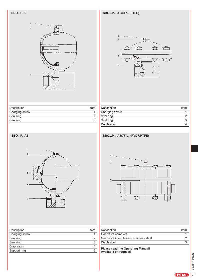
sBO...p-...a6/347...(pTFe)
pulsation dampers for aggressive media
Pulsation damper in stainless steel with PTFE coated diaphragm and PTFE or FFKM seals. Also available without connection block.
Certification to PED 97/23/EC
Permitted operating temperature: -15 °C ... +80 °C
Permitted pressure ratio p2 : p0 = 2 : 1
Nominal volume [l]
Max. operating pressure [bar]
Weight [kg]
A [mm]
B [mm]
Ø D [mm]
E [mm]
H [mm]
J 1) thread ISO 228
0.2 40 11 140
60
210
105 30 g 1250 27 197 230
0.5 40 12 165 210
250 26 200 2301) Standard connection code = AI, others on request
sBO...p-...a4/777... (pVdF/pTFe)
Pulsation damper in PVDF with PTFE-coated diaphragm.
Permitted operating temperature: -10 °C ... +65 °C
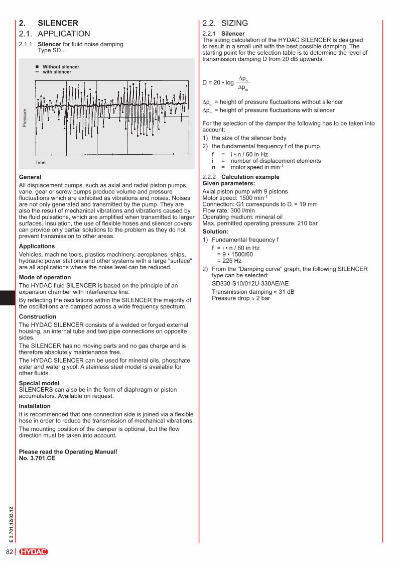
2.2. SIzINg2.2.1 silencerThe sizing calculation of the HYDAC SILENCER is designed to result in a small unit with the best possible damping. The starting point for the selection table is to determine the level of transmission damping D from 20 dB upwards.
For the selection of the damper the following has to be taken into account:1) the size of the silencer body2) the fundamental frequency f of the pump. f = i • n / 60 in Hz
i = number of displacement elements n = motor speed in min-1
2.2.2 calculation exampleGiven parameters:Axial piston pump with 9 pistons Motor speed: 1500 min-1 Connection: G1 corresponds to Di = 19 mm Flow rate: 300 l/min Operating medium: mineral oil Max. permitted operating pressure: 210 barsolution:1) Fundamental frequency f f = i • n / 60 in Hz
= 9 • 1500/60 = 225 Hz
2) From the "Damping curve" graph, the following SILENCER type can be selected:
SD330-S10/012U-330AE/AE Transmission damping ≈ 31 dB
Pressure drop ≈ 2 bar
Dpo = height of pressure fluctuations without silencerDpm = height of pressure fluctuations with silencer
2. sileNcer2.1. APPlICATION2.1.1 silencer for fluid noise damping
Type SD...
Without silencer – with silencer
Pre
ssur
e
Time
GeneralAll displacement pumps, such as axial and radial piston pumps, vane, gear or screw pumps produce volume and pressure fluctuations which are exhibited as vibrations and noises. Noises are not only generated and transmitted by the pump. They are also the result of mechanical vibrations and vibrations caused by the fluid pulsations, which are amplified when transmitted to larger surfaces. Insulation, the use of flexible hoses and silencer covers can provide only partial solutions to the problem as they do not prevent transmission to other areas.
applicationsVehicles, machine tools, plastics machinery, aeroplanes, ships, hydraulic power stations and other systems with a large "surface" are all applications where the noise level can be reduced.
mode of operationThe HYDAC fluid SILENCER is based on the principle of an expansion chamber with interference line.By reflecting the oscillations within the SILENCER the majority of the oscillations are damped across a wide frequency spectrum.
constructionThe HYDAC SILENCER consists of a welded or forged external housing, an internal tube and two pipe connections on opposite sides.The SILENCER has no moving parts and no gas charge and is therefore absolutely maintenance free.The HYDAC SILENCER can be used for mineral oils, phosphate ester and water glycol. A stainless steel model is available for other fluids.
special model SILENCERS can also be in the form of diaphragm or piston accumulators. Available on request.
installationIt is recommended that one connection side is joined via a flexible hose in order to reduce the transmission of mechanical vibrations.The mounting position of the damper is optional, but the flow direction must be taken into account.
please read the Operating manual! No. 3.701.ce
D = 20 • logDpo
Dpm
83
E 3.
701.
12/0
3.12
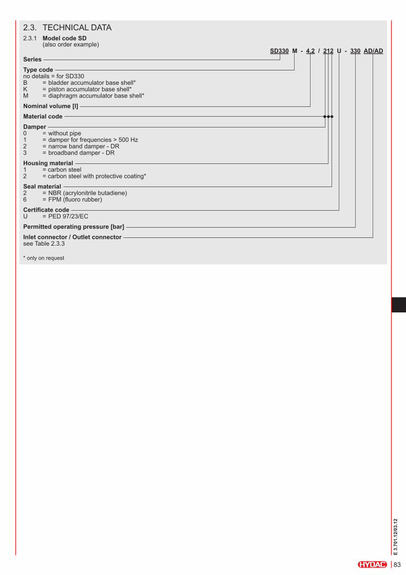
2.3. TECHNICAl DATA2.3.1 model code sd
(also order example)sd330 m - 4,2 / 212 u - 330 ad/ad
seriesType code no details = for SD330 B = bladder accumulator base shell* K = piston accumulator base shell* M = diaphragm accumulator base shell*
Nominal volume [l]material codedamper 0 = without pipe 1 = damper for frequencies > 500 Hz 2 = narrow band damper - DR 3 = broadband damper - DR
Housing material 1 = carbon steel 2 = carbon steel with protective coating*
seal material 2 = NBR (acrylonitrile butadiene) 6 = FPM (fluoro rubber)
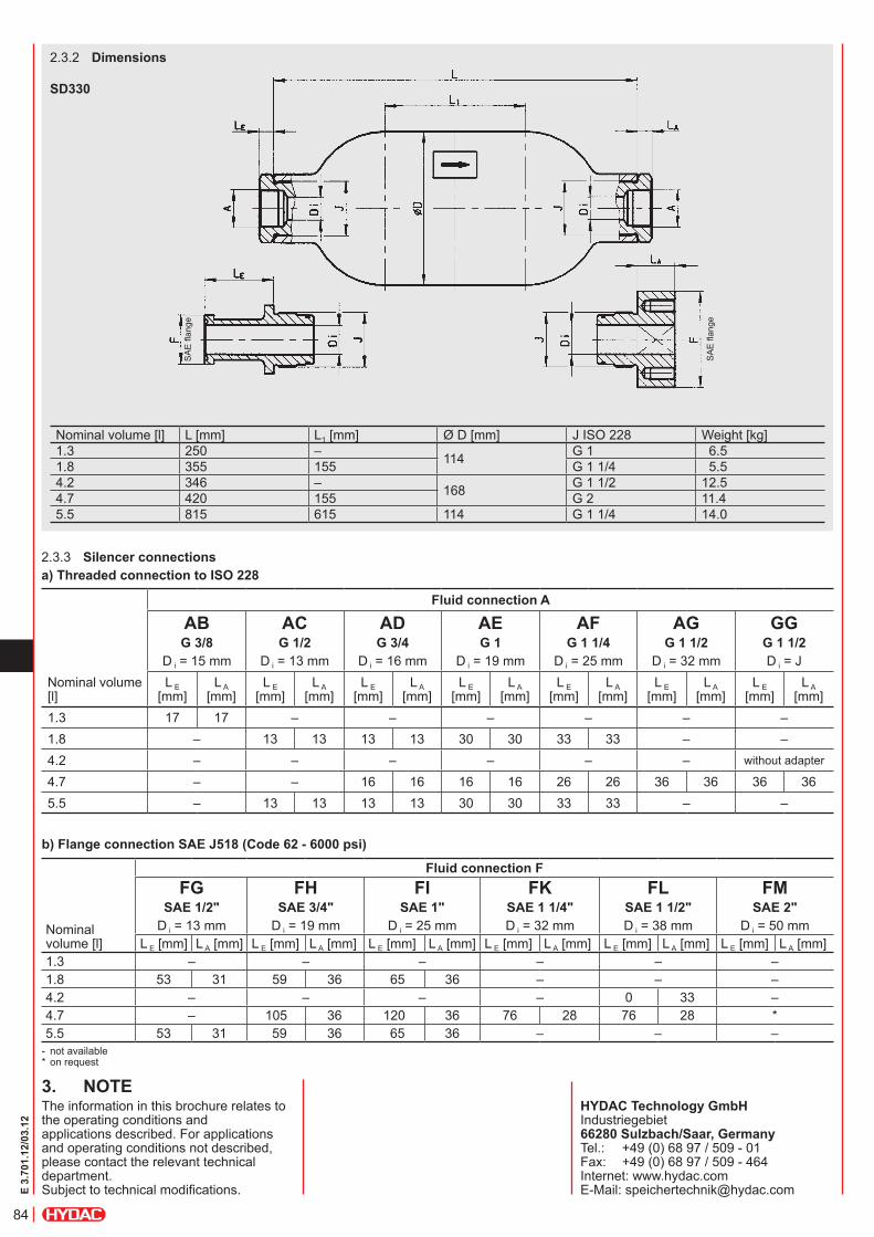
2.3.3 silencer connectionsa) Threaded connection to isO 228
- not available * on request
b) Flange connection sae J518 (code 62 - 6000 psi)
3. NOTeThe information in this brochure relates to the operating conditions and applications described. For applications and operating conditions not described, please contact the relevant technical department. Subject to technical modifications.