22
HYDRAULIC FAN DRIVE SYSTEMS HYDRAULIC SYSTEMS DIVISION Outstanding Hydraulic Products, Service and Expertise, Worldwide

HYDRAULIC FAN DRIVE SYSTEMS
HYDRAULIC SYSTEMS DIVISION Outstanding Hydraulic Products, Service and Expertise, Worldwide

Haldex Hydraulic Fan Drives
The Haldex fan drive offering includes systems that range from simple to complex. System designers canchoose the option best suited to the design criteria driving each vehicle and cooling system project. The fandrive systems and components within this catalog are not all inclusive regarding system solutions. For in-stance, the fan drive system may also be integral to the hydrostatic drive charge pump system, the brakecharging system, the pilot control valve system, etc. Haldex has provided fan drive system solutions for allthese and many other types of integrations. Solutions from the vehicle perspective are one of our core com-petencies. We have many other products (pumps, electrohydraulic power systems, valves, etc.) that may beapplicable to your application. Therefore, if you do not find the specific solution within this catalog, contactHaldex for assistance. We will engineer a solution specifically for your vehicle.
2
Pictures on front cover are used with the kind permission of eg: Atlet, BT, Huddig, Scania, Toro and Volvo Construction Equipment.
VehicleHost Control
ECM
WM900Motor
W900Pump
Reservoir
The demand for increased energy savings, reduced emissions and reduced noise in vehicles is requiring thatvehicle engineers question traditional design approaches and traditional systems. One area of focus onvehicles ranging from buses to excavators is cooling systems.
Haldex fan drive systems offer significant advantages to cooling system designers when compared to tradi-tional belt and electric fan drive systems. These advantages include:
• Fan speed independent of engine speed• Precise control of coolant temperature• On-Demand cooling capability which eliminates excess power consumption• Reduced noise• Reduced emissions• Flexibility in cooling system design

Table of Contents
Basic Systems & Selection Criteria ............................................................................................................ 2 - 4System Descriptions ................................................................................................................................. 5 - 10How To Apply A Fan Drive System ................................................................................................................ 11Recommended Application Data Information .......................................................................................... 12 - 13Haldex Pumps & Hydraulic Motor Quick Reference Chart ........................................................................... 14Ordering Guide ............................................................................................................................................. 15Controls Capability .................................................................................................................................. 16 - 20
Haldex is a leader in the design and application of Hydraulic Fan Drive systems. This catalog has beendesigned to be a tool to assist you in selecting the fan drive system that best meets your vehicle needs. Asimple guide to mating the system to your objectives is included on Page 4. Pages 5-10 outline each type offan drive system and the various circuits available for each type of system. The systems are:
• Follows Engine Speed
• On / Off
• Independently Variable
• Two Speed
A typical performance map is included for each circuit along with a circuit diagram. A very detailed guide toapplying a fan drive system is featured on Page 11. A quick reference to the full line of Haldex pumps andfluid motors is included on Page 14. The catalog also describes the electronic controls that are available forcontrolling fan drive systems as well as guidance in specifying the control parameters required for your sys-tem.
When used in conjunction with the Haldex Hydraulic Motor catalog, this catalog allows for the fan drive sys-tem you have chosen to be specified by model code. In addition, a staff of knowledgeable applicationsspecialists is available to assist you with any of your custom requirements.
About This Catalog 3

Follows Engine SpeedNo Over Speed w/ Over Speed
Protection Protection On / Off Independently Variable 2 Speed
9 Cost
Noise
7 Temperature control
Efficiency
TOTALS
An On / Off will be most likely to fit your needs for your hydraulic fan drive system. Of course, othersystem parameters may override this choice.
Selecting The Best System For Your Needs
The system drivers shown on the "Y" axis generally provide an initial indication of the basic type of fan drive system to pursue:
INSTRUCTIONS:
1. Choose your most important drivers (cost, noise, temperature control or efficiency) for determiningthe appropriate fan drive system. You may choose any number of these drivers.
2. Assign a number between 1 and 10 for importance to the drivers you have chosen (10 being thehighest importance).
3. Place these numbers in the boxes to the left of the drivers.
4. Multiply the importance number by the number in each circuit column.(ex. check valve circuit: 5, 1, 1, 1, etc.) Then put that product into the box to the right.
5. Total the numbers in the boxes for each circuit column. The highest total represents thesystem that will most likely fit your needs.
Matrix of criteria vs. type of hydraulic fan drive systems. Select two drivers.
Follows Engine SpeedNo Over Speed w/ Over Speed
Protection Protection On / Off Independently Variable 2 Speed
Cost
Noise
Temperature control
Efficiency
TOTALS
5
1
1
1
4
2
2
2
3
3
4
4
1
5
5
5
2
4
3
3
EXAMPLE: Assuming Cost and Temperature Control are the most important drivers.Cost is ranked as a 9 and Temperature Control as a 7. (See scenario below.)
5 45
1
1 7
1
52
4 36
2
2 14
2
50
3 27
3
4 28
4
55
1 9
5
5 35
5
44
2 18
4
3 21
3
39
4

System Descriptions
FAN DRIVE SYSTEMS: Follows Engine SpeedNo Over Speed Protection
Circuit 1 - Check valve to prevent cavitation during deceleration and spin-down.
PERFORMANCE(Circuit 1)
* Length adder to Hydraulic Motor Catalog max. length dimension, mm [inch].E.G. WM900 L above = 32 mm. WM900 max. length in Motor Catalog - pg 16 (X dim.) = 111 mm [4.37 in.] for19 cc. Therefore, 32 mm + 111 mm = 143 mm [5.62 in.] max. length.
WM600 WM900 WM1500 GM20 GM30
FAMILY
WM600
WM900
WM1500
GM20
GM30
L*
13 [.51]
32 [1.25]
40 [1.57]
32 [1.25]
35 [1.37]
W
77 [3.03]
88 [3.46]
115 [4.52]
149 [5.86]
171 [6.73]
H
86 [3.38]
106 [4.17]
135 [5.31]
164 [6.45]
183 [7.2]
FAN DRIVE SYSTEMS: Follows Engine Speedw/ Over Speed Protection
Circuit 2 - Relief valve to limit the maximum motor speed and protect the motorfrom over-pressurization.
* Length adder to Hydraulic Motor Catalog max. length dimension, mm [inch].E.G. WM900 L above = 32 mm. WM900 max. length in Motor Catalog - pg 16 (X dim.) = 111 mm [4.37 in.] for19 cc. Therefore, 32 mm + 111 mm = 143 mm [5.62 in.] max. length.
WM600 WM900 WM1500 GM20 GM30
FAMILY
WM600
WM900
WM1500
GM20
GM30
L*
37 [1.45]
32 [1.25]
40 [1.57]
32 [1.25]
35 [1.37]
W
140 [5.51]
88 [3.46]
113 [4.44]
148 [5.82]
171 [6.73]
H
86 [3.38]
130 [5.11]
144 [5.66]
170 [6.69]
213 [8.38]
PERFORMANCE(Circuits 2, 3 & 8)
5

FAN DRIVE SYSTEMS: Follows Engine Speedw/ Over Speed Protection
Circuit 8 - Check valve to prevent cavitation during deceleration and spin-down, a solenoidvalve to control the direction of flow through the motor and a cross-over relief valve tolimit the maximum motor speed and protect the motor from over-pressurization in bothdirections.
* Length adder to Hydraulic Motor Catalog max. length dimension, mm [inch].E.G. WM900 L above = 49 mm. WM900 max. length in Motor Catalog - pg 16 (X dim.) = 111 mm [4.37 in.] for19 cc. Therefore, 49 mm + 111 mm = 160 mm [6.29 in.] max. length.
WM600 WM900 WM1500
FAMILY
WM600
WM900
WM1500
L*
47 [1.85]
49 [1.92]
51 [2]
W
197 [7.75]
238 [9.37]
243 [9.56]
H
91 [3.58]
115 [4.52]
141 [5.55]
System Descriptions (cont.)
FAN DRIVE SYSTEMS: Follows Engine Speedw/ Over Speed Protection
Circuit 3 - Check valve to prevent cavitation during deceleration and spin-downand a relief valve to limit the maximum motor speed and protect the motor fromover-pressurization.
* Length adder to Hydraulic Motor Catalog max. length dimension, mm [inch].E.G. WM900 L above = 40 mm. WM900 max. length in Motor Catalog - pg 16 (X dim.) = 111 mm [4.37 in.] for19 cc. Therefore, 40 mm + 111 mm = 151 mm [5.94 in.] max. length.
WM600 WM900 WM1500 GM20 GM30
FAMILY
WM600
WM900
WM1500
GM20
GM30
L*
37 [1.45]
40 [1.57]
40 [1.57]
32 [1.25]
35 [1.37]
W
138 [5.43]
90 [3.54]
160 [6.29]
148 [5.82]
171 [6.73]
H
89 [3.5]
130 [5.11]
135 [5.31]
180 [7.08]
213 [8.38]
PERFORMANCE(Circuits 2, 3 & 8)
PERFORMANCE(Circuits 2, 3 & 8)
6

System Descriptions (cont.)
FAN DRIVE SYSTEMS: On / Off
Circuit 4 - Relief valve to limit the maximum motor speed and prevent themotor from over-pressurization and a solenoid valve to bypass flow around the motor.
* Length adder to Hydraulic Motor Catalog max. length dimension, mm [inch].E.G. WM900 L above = 92 mm. WM900 max. length in Motor Catalog - pg 16 (X dim.) = 111 mm [4.37 in.] for19 cc. Therefore, 92 mm + 111 mm = 203 mm [7.99 in.] max. length.
WM600 WM900 WM1500 GM20 GM30
FAMILY
WM600
WM900
WM1500
GM20
GM30
L*
37 [1.45]
92 [3.62]
40 [1.57]
32 [1.25]
35 [1.37]
W
138 [5.43]
90 [3.54]
177 [6.96]
148 [5.82]
171 [6.73]
H
137 [5.39]
130 [5.11]
144 [5.66]
230 [9.05]
239 [9.4]
NOTE: Valve coils not shown for clarity.
PERFORMANCE(Circuit 4)
* Length adder to Hydraulic Motor Catalog max. length dimension, mm [inch].E.G. WM900 L above = 48 mm. WM900 max. length in Motor Catalog - pg 16 (X dim.) = 111 mm [4.37 in.] for19 cc. Therefore, 48 mm + 111 mm = 159 mm [6.25 in.] max. length.
WM600 WM900 WM1500
FAMILY
WM600
WM900
WM1500
L*
29 [1.14]
48 [1.88]
33 [1.29]
W
144 [5.66]
146 [5.74]
155 [6.1]
H
137 [5.39]
137 [5.39]
167 [6.57]
Circuit 10 - Check valve to prevent cavitation during deceleration and spin-down, a thermal pilot-operatedwax capsule to activate the relief valve at a specific temperature, a relief valve to limit the maximum fan speed andprotect the motor from over-pressurization and a needle valve for field adjusting the relief valve (if required) and theminimum motor speed. Note: This system only monitors the fluid running through it (no external signal available).
PERFORMANCE(Circuit 10)
7
System Descriptions (cont.)
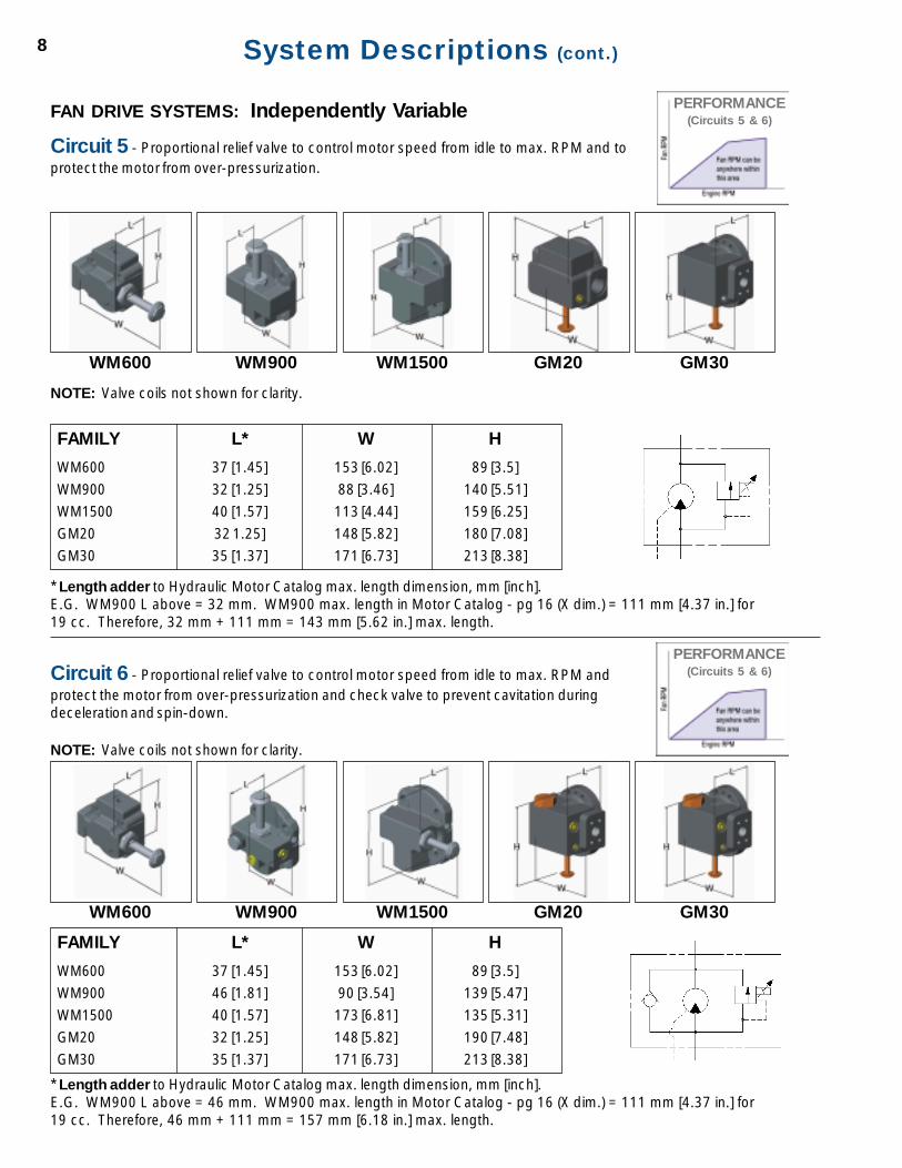
FAN DRIVE SYSTEMS: Independently Variable
Circuit 5 - Proportional relief valve to control motor speed from idle to max. RPM and toprotect the motor from over-pressurization.
* Length adder to Hydraulic Motor Catalog max. length dimension, mm [inch].E.G. WM900 L above = 32 mm. WM900 max. length in Motor Catalog - pg 16 (X dim.) = 111 mm [4.37 in.] for19 cc. Therefore, 32 mm + 111 mm = 143 mm [5.62 in.] max. length.
WM600 WM900 WM1500 GM20 GM30
FAMILY
WM600
WM900
WM1500
GM20
GM30
L*
37 [1.45]
32 [1.25]
40 [1.57]
32 1.25]
35 [1.37]
W
153 [6.02]
88 [3.46]
113 [4.44]
148 [5.82]
171 [6.73]
H
89 [3.5]
140 [5.51]
159 [6.25]
180 [7.08]
213 [8.38]
NOTE: Valve coils not shown for clarity.
* Length adder to Hydraulic Motor Catalog max. length dimension, mm [inch].E.G. WM900 L above = 46 mm. WM900 max. length in Motor Catalog - pg 16 (X dim.) = 111 mm [4.37 in.] for19 cc. Therefore, 46 mm + 111 mm = 157 mm [6.18 in.] max. length.
WM600 WM900 WM1500 GM20 GM30
FAMILY
WM600
WM900
WM1500
GM20
GM30
L*
37 [1.45]
46 [1.81]
40 [1.57]
32 [1.25]
35 [1.37]
W
153 [6.02]
90 [3.54]
173 [6.81]
148 [5.82]
171 [6.73]
H
89 [3.5]
139 [5.47]
135 [5.31]
190 [7.48]
213 [8.38]
Circuit 6 - Proportional relief valve to control motor speed from idle to max. RPM andprotect the motor from over-pressurization and check valve to prevent cavitation duringdeceleration and spin-down.
NOTE: Valve coils not shown for clarity.
PERFORMANCE(Circuits 5 & 6)
PERFORMANCE(Circuits 5 & 6)
8

System Descriptions (cont.)
* Length adder to Hydraulic Motor Catalog max. length dimension, mm [inch].E.G. WM900 L above = 50 mm. WM900 max. length in Motor Catalog - pg 16 (X dim.) = 111 mm [4.37 in.] for19 cc. Therefore, 50 mm + 111 mm = 161 mm [6.33 in.] max. length.
WM600 WM900 WM1500
FAMILY
WM600
WM900
WM1500
L*
48 [1.88]
50 [1.96]
41 [1.61]
W
182 [7.16]
184 [7.24]
192 [7.55]
H
91 [3.58]
112 [4.4]
135 [5.31]
Circuit 9 - Proportional flow control to control the fan speed from idle to max.RPM including a load sense shuttle valve. Primarily used with closed center pistonpump systems.
NOTE: Valve coils not shown for clarity.
PERFORMANCE(Circuit 9)
9

System Descriptions (cont.)
* Length adder to Hydraulic Motor Catalog max. length dimension, mm [inch].E.G. WM900 L above = 49 mm. WM900 max. length in Motor Catalog - pg 16 (X dim.) = 111 mm [4.37 in.] for19 cc. Therefore, 49 mm + 111 mm = 160 mm [6.29 in.] max. length.
WM600 WM900 WM1500
FAMILY
WM600
WM900
WM1500
L*
37 [1.45]
49 [1.92]
40 [1.57]
W
138 [5.43]
152 [5.98]
166 [6.53]
H
137 [5.39]
112 [4.4]
135 [5.31]
FAN DRIVE SYSTEMS: Two-Speed
Circuit 7 - Check valve to prevent cavitation during deceleration and spin-down, a relief valve to limitthe maximum motor speed and protect the motor from over-pressurization and a solenoid valveto provide two-speed operation.
NOTE: Valve coils not shown for clarity.
PERFORMANCE(Circuit 7)
10

Step by Step instructions on how to apply a Fan Drive System. The balance of the fan drive information is to be filled inon the Fan Drive Application Data sheets (see pages 12 and 13). NOTE: Formula numbers in bold and circled corre-spond to numbers in bold and circled in Application Data Sheets on pages 12 and 13.
How To Apply A Fan Drive System
Determine critical fan speed, NM at a specified engine speed, NE (RPM).
2. Determine fan power, HP, or torque, TM required at the critical speed. (HP or ft-lbs)
Convert power to torque, if necessary.
MM N
HPlbsftT
5252)(
×=−
Determine fan system operating pressure, P at the critical speed. (PSI)
This pressure is up to the designer’s discretion and depends on several factors including pressure ratings for system components, componentsizes and system life requirements. Pump and motor sizes will be smaller with higher pressures but system life reduces as pressure increases. Also,any “under hood” regulations should be considered.
Calculate motor displacement.
P
TccD M
M
1374)(
×=
Calculate flow required, QM for the motor at critical speed.
3485)( MM
M
NDGPMQ
×=
If a clipping relief valve is not being used in the motor, required pump flow, QP = QM - Skip to step 8.
Determine additional flow, QA, to allow over the relief valve to compensate for temperature variations and component wear for maintaining a
consistent fan speed (at critical fan speed NM). Add this to the required motor flow, QM to get the flow required from the pump. QP
AMP QQGPMQ +=)(
This flow is up to the designer’s discretion. It is safe to assume a 10% reduction in system volumetric efficiency over its life. Also, it is safe toassume a 5-10% reduction in volumetric efficiency at oil temperatures exceeding 180°F. In order to compensate for these factors, the pump canbe sized for additional flow.
Note: This additional flow will be discharged over the relief valve at system pressure. This should be calculated into the total heat loadrequirements of the system.
Determine pump speed, NP at the specified engine speed, NE (RPM).
This is determined from the engine to pump speed ratio. Example: If the ratio of engine speed to pump speed is 1:1.2, 2.1×= EP NN
Calculate pump displacement.
P
PP N
QccD
4030)(
×=
Calculate required maximum input torque, TP for the pump.
68)( P
P
DPlbsftT
×=−
This is required for selecting the type of shaft end (i.e. 9 tooth vs. 11 tooth spline, etc.) and provides for engine HP loss to drive fan at maximumcondition.
11. Select the proper pump and motor series based on displacements, pressure, shaft loading, mounting requirements, etc. from the Haldex pumpand fluid motor families. See catalog page 14 to begin family selection.
Note: The pump and motor efficiencies assumed in the equations above are conservative to insure that the system is not under cooled.Variables:
NM Motor Speed (RPM) QM Motor Input Flow (GPM) DP Pump Displacement (cc)
NP Pump Speed (RPM) QP Pump Output Flow (GPM) DM Motor Displacement (cc)
NE Engine Speed (RPM) TM Motor Output Torque (ft-lbs) P Fan System Pressure (PSI)
HP Fan Power (HP) TP Pump Input Torque (ft-lbs) QA Additional Flow over RV (GPM)
See Application Data Sheets on pages 12 & 13.
11
1
10
9
8
7
6
5
4
3
1115

Fan Drive System Application Data Sheet
Note: Note: Note: Note: Note: Transfer the items from each step in the fan drive sizing procedure on page 11 to the spaces below (and right) withcircled numbers in bold.
Contact: Motor Project #:
Phone: Pump Project #:
Fax: Date:
Customer: Originator:
Address: Motor Target Price: Pump Target Price:
City, State, Zip: E.A.U.:
E-mail Address:
Competitive Information (model #, current problems, etc.):
System Information
Application Description:
Maximum System Pressure:
Fluid Type:
Viscosity Range:
Temp. Range:
Filtration Level:
Ambient Temp. Range:
Design Life Requirement:
Noise Limitations:
Motor Information
Customer P/N: Current Supplier:
Displacement:
Motor Model Code (If Known):
Valve Model Code (If Known):
Fan Speed Range: Torque Range:
Critical Fan Speed: Torque at Critical Speed:
Supply Flow Range: Pressure at Critical Speed:
Recommended Application Data Information12
5
1 34
Hydraulic Circuit:

Recommended Application Data Information (cont.) 13
Flow Required at Critical Speed:
Maximum Outlet Pressure: Is Case Drain Acceptable? : Yes / No
Rotation (looking at fan motor shaft): CW / CCW / Bi-rotational
Flange Style: Shaft Style:
Seal and Outboard Ball Bearing Requirements:
Dust Seal : Yes / No
Radial Shaft Load: ________ @ ________ RPM Axial Shaft Load: ________ @ ________ RPM
Inlet Port Size: Outlet Port Size:
Valving Requirements:
Relief Valve Setting: ________ @ ________ Fan RPM Does RV Limit Fan Speed? Yes / No
Flow Allowed Over RV for Wear / Temperature Variations:
Solenoid Coil Voltage: Solenoid Coil Connector Style:
Proportional Controller Required? Yes / No If Yes, see Controller Requirements on pages 16 - 20.
Envelope Restrictions (L x W x H):
Motor Shaft Orientation (horizontal, vertical, other: describe):
Pump InformationCustomer P/N: Current Supplier: Displacement:
Pump Model Code (if known):
Valve Model Code (if known):
Engine RPM Range: Engine to Pump RPM Ratio:
Critical Engine Speed: Pump Flow at Critical Speed:
Pump Input Torque:
Rotation: CW / CCW
Flange Style: Shaft Style:
Wet Mount: Yes / No
Seal and Outboard Ball Bearing Requirements:
Are Dual Seals and a Weep Hole Required? Yes / No
Radial Shaft Load: ________ @ ________ RPM Axial Shaft Load: ________ @ ________ RPM
Inlet Port Size: Outlet Port Size:
Valving Requirements:
Envelope Restrictions (L x W x H):
Fan InformationManufacturer: Contact:Diameter: Material:Weight: Max. Rated Speed:Balance Specification:Torque vs. Speed Equation (supply curve if available):Thrust vs. Speed Equation (supply curve if available):Push / Pull Relative to Motor Shaft:
6
7
9
871
10

Haldex offers one of the widest selections of gear pumps and hydraulic motors in the industry. All Haldex products aredesigned to provide solutions to our customers' application challenges. Haldex pumps and motors are used for fan drivesystems on skid steer loaders, wheel loaders, excavators, paving equipment, buses and forklifts. Leading equipment manu-facturers throughout the mobile equipment market specify these components. The Haldex line of hydraulic pumps andmotors covers a displacement range from .065 in.3 to 9.82 in.3. The various series include cast iron fixed clearance, alumi-num body pressure balanced and cast iron pressure balanced designs. Both unidirectional and birotational configurations areavailable. Each series offers a large selection of shaft, flange and valve options to meet your application requirements.
Haldex Pump & Fluid Motorsfor Fan Drive Systems
14
Special fixed displacement product. Sizing characteristics differ from those shown in this catalog.Contact factory for assistance.*
NOTE: As can be seen from the above quick reference chart, a displacement selection may cross several differentpump or motor families (frame sizes). Frame sizes overlap intentionally. This provides capability in one frame size that isnot achievable in another. For instance, the example illustrates that the displacement selected (27cc) is available in theWM900 and WM1500 motor. The WM1500 has higher bearing side load capability and pressure capability, but is not aseconomical as the WM900 model. If the application does not need these additional capacities in pressure and load, theWM900 would be the motor of choice; i.e. best value. For a full illustration of the family capability, please refer to thespecific product catalog (Haldex Hydraulic Motor Catalog, W900 Pump Catalog, etc.).
Quick Reference Chart
.065 .129 .517 .732 1.50 2.00 3.00 4.00 5.00 6.00 7.00 8.00 9.821 cc 2 cc 8 cc 12 cc 24 cc 33 cc 50 cc 65 cc 82 cc 98 cc 114 cc 131 cc 161 cc
Displacement (in.3/rev.)(cc/rev)
WM600 Series
WM900 Series
WM1500 Series
GM20 Series
GM30 Series
GC Series
1.6527 cc
*
.065 .129 .517 .732 1.50 2.00 3.00 4.00 5.00 6.00 7.00 8.00 9.821 cc 2 cc 8 cc 12 cc 24 cc 33 cc 50 cc 65 cc 82 cc 98 cc 114 cc 131 cc 161 cc
Displacement (in.3/rev.)(cc/rev)
W600 Series
W900 Series
D Series
W1500 Series
G20 Series
GM30 Series
GC Series
1.6527 cc
*
*
Motors
Pumps

Fan Drive System Ordering Information 15
Each Fan Drive option has been assigned an order code which islisted in the tables below. Configure the desired options as shownin the example model code to the right.
Note: The fan drive order code is a suffix to the WM600, WM900& WM1500 motor order code as shown in the example below. Thefan drive order code for the GM20 & GM30 appears in the middleof the model code as shown in the example below.
3. RELIEF VALVE SETTING
R**** Available in 100 PSI incrementsto 3000 PSI. Consult factory
**** for higher pressures.Proportional Relief Valve has amax. setting. Choose 1000, 2000or 3000 PSI only.
NN Not Applicable
NOTE: WM600 Relief Valve has a max.setting of 2600 PSI. Consult factory forhigher settings.
4. FLOW FOR RV SETTINGSpecify the flow at which the reliefvalve is to be set. (RV will be set at0.25 GPM, if not specified.)
F ** Relief flow multiplied by 10.Available in 0.5 GPM incrementsfrom 2 to 8 GPM.
NN Not Applicable
Example: F45The relief valve will be set at thespecified pressure with a full-bypassflow of 4.5 GPM.
All values assume 32cSt (151 SSU)viscosity.
6. COIL VOLTAGE010 10 VDC012 12 VDC024 24 VDC036 36 VDC048 48 VDCNN NOT APPLICABLE
5. SOLENOID PRESSURE RATINGSF < 3000 PSINN Not Applicable
7. TERMINATION TYPEDS Dual SpadesDL Leadwires (2)DM Leads with Metripak-150 ConnectorsDD DIN 43650 ConnectorNN NOT APPLICABLE
2. VALVE OPTIONFor Normally Closed Two-Way Solenoid ValveOptions MD & ME, an orifice has to be specified.Orifice size is application dependent. Pleasecontact factory to determine size.For Thermo Valve Option TA ONLY(Specify temperature setting):Model Description
40 40ºC (104ºF)50 50ºC (122ºF)55 55ºC (131ºF)60 60ºC (140ºF)
For Proportional Valve Options PA, PB,PC & PD ONLY(Specify proportional valve controller):Model Description
01 Proportional Valve Controller - Coil Mounted02 Proportional Valve Controller - RemoteNN Not Applicable
1. VALVE TYPEMODEL Circuit Page FamilyCODE DESCRIPTIONS # # W600 W900 / W1500 G20 /G30
GE Overrunning Check Valve, Integral 1 5 •GF Overrunning Check Valve, Cartridge 1 5 • •FA Relief Valve 2 5 • • •HP Overrunning Check Valve and Relief Valve 3 6 •
(Integral CV & Cartridge RV)
HR Overrunning Check Valve and Relief Valve 3 6 • •(Cartridge CV & RV)
MB Normally Closed Two-Way Solenoid Valve 4 7 • • •with Relief Valve (Cartridge RV)
PA Proportional Relief Valve Only 5 8 • • •PB Proportional Relief Valve with Check Valve 6 8 •
(Integral CV)
PC Proportional Relief Valve with Check Valve 6 8 • •(Cartridge CV)
MD Normally Closed Two-Way Solenoid Valve 7 10 •with Check Valve and Relief Valve (Integral
CV & Cartridge RV)
ME Normally Closed Two-Way Solenoid Valve 7 10 •with Check Valve and Relief Valve
(Cartridge CV & RV)
RA 2-Position, 4-Way Solenoid Valve, Cross- 8 6 •Over Relief Valve and Check Valve
(Integral CV)
RB 2-Position, 4-Way Solenoid Valve, Cross- 8 6 •Over Relief Valve and Check Valve
(Cartridge CV)
PD Proportional Flow Control with Shuttle Valve 9 9 • •TA Thermo Valve 10 7 • •
1 2 3 4 5 6 7
ORDER CODE
VALV
E O
PTI
ON
REL
IEF
VALV
E
SETT
ING
FLO
W F
OR
RV
SETT
ING
SOLE
NO
ID T
YPE
CO
IL V
OLT
AG
ETE
RM
INA
TIO
N
TYP
E
VALV
E T
YP
E
EXAMPLE MB NN R1200 F45 SF 024 DS
Your Options
The descriptions and circuit numbers below correspond to the circuits on pages 5 through 10.
Sample WM900 Motor Model Code from Hydraulic Motor Catalog, page 21, followed by Fan Drive Model Code shown above:
WM900 Motor Fan Drive WM09A1 / B / 190 / R / 03 / FA / 103 MB / NN / R1200 / F45 / SF / 024 / DS
Sample GM20 Motor Model Code from Hydraulic Motor Catalog, page 41, with Fan Drive Model Code shown above in between:
GM20 Motor Fan Drive GM20 Motor P1 - GM20D - 2W15V11H MBNNR1200SF024DS A1261L
(WM600 & WM1500 are similar to the WM900example shown here.)
(GM30 is similar to the GM20 example shownhere.)

Haldex offers a complete line of Fan Drive electronic controls that interface directly with the electrohydraulicFan Drive packages. These range in complexity from simple proportional plug and play controls that plugdirectly into the electrohydraulic valve coil, to stand alone electronic control packages that operate the entirefan drive control system. The controls illustrated demonstrate the spectrum of features available to the OEM.Haldex will assist the OEM in the control specification to achieve the optimum system for the specific vehicle.
GENERAL OPERATION OF THE HALDEX FAN DRIVE CONTROLLERS
Fan drive controllers are designed to control the pressure relieving electro-proportional cartridge valves aspart of a proportional fan-drive system. Since fan torque is a cubic function relative to speed, it is moreeconomical to control fan speed using pressure control than flow control. These controllers range insophistication from simple on-off inputs to multiple sensor proportional inputs and are designed to fit theneeds of rugged off-highway vehicles.
The controllers illustrated operate on the principle that temperature is to be proportionally controlledbetween design set points. They provide the necessary output to the electrohydraulic proportional valve inthe fan drive system allowing precise fan motor speed correlated to temperature. The inputs can range froma temperature switch providing a voltage input to the controller, to an analog sensor input correlated totemperature.
The controllers illustrated in this catalog are typical of the two types developed specifically for fan drivesystems. However, special controllers can be developed for higher volume OEM applications.
INTEGRAL PLUG-IN CONTROLLERS
DESCRIPTIONThese controllers are designed for single input temperature control. They consist of a series of convenient,plug-mounted control amplifiers for controlling the fan drive proportional valves. These valve solenoids andcontrollers have DIN 43650/ISO 4400 electrical connectors. These controllers come in a variety of input andoutput configurations and adjustments.
OPERATIONThis control module utilizes high frequency switching (PWM) to supply a proportional valve solenoid with aninput signal that is proportional to an external signal. The external signal can be from a 10K potentiometer,0–5 VDC, 0-10 VDC, 0–20 mA, or from other pre-set levels. NOTE: Simplified controllers are also avail-able (re: ramping only) NOTE: These controllers fail to full fan speed mode.
TYPICAL FEATURES• Mounts directly to solenoid coils with DIN 43650A connectors.• IP65 internal protection (IEC529).• Adjustments accessible with a removable cover.• No internal fuses; circuit limits current electronically.• Short circuit proof and reverse polarity protected.• Connector can be disconnected from coil when powered.• Maximum current adjustment does not affect minimum current setting.• Independent ramp adjustments and internal supply for potentiometer.• Fails to full fan speed.
Controls Capability16

TYPICAL RATINGSSupply Voltage: 9–32 VDCControl Input Signal Options: 10 K external potentiometer (accepts 5K to 50K pots), or 0–5 VDC signal,0-10 VDC signal, or 0–20 mA current signal.Input Resistance: Voltage Control: 125K Ohms; Current Control: 50K OhmsRamp Up and/or Down: 0.01–5.0 seconds (independently adjustable)Operating Conditions: –20° to 85°C (-4º to 185ºF); 0 to 85% relative humidity
REMOTE MOUNTED CONTROLLER
(See Page 20 for illustration)
Description:These controllers are designed for multiple input temperature control. Power supply input is 12 or 24VDC (nominal). The controller accepts up to three analog temperature sensor inputs and up to two digitalinputs. The OEM can select the number of temperature inputs by setting a DIP switch on the controller.NOTE: Once specified, these can be factory preset by Haldex. The temperature range accepted by thecontroller is set by the sensor specifications. See Page 19 for sensor input requirements. The controllercompares the actual value of the temperature inputs with programmed setpoints (specified by the OEM) togenerate a proportional current output to the valve. The valve proportionally controls the pressure at the fanmotor and therefore motor speed. Proportional control occurs when the temperature sensor inputs fallwithin the minimum and maximum temperature setpoints of the controller. Turning on the digital inputcauses the controller to ramp for a 2.5 second period from maximum current output (idle fan speed) to thenecessary current output required to achieve set point fan speed. The fan cools by operating between astarting fan speed and a maximum fan speed, which are determined by the cooling system layout. Theserequirements should be specified on Page 19 (sensor inputs). Calibrating the controller potentiometer andtuning the pressure setting of the valve sets both speeds. Digital inputs can also be set to actuate full fanspeed mode when required for engine retarding or other applications where high heat loads are generated.Idling speed is the mode of operation of the fan when it is not required to cool. The controller and propor-tional valve are designed to provide a maximum fan speed in the cooling circuit in case of a power loss.
Overcurrent protection is provided. Once an overcurrent situation is detected, the controller output turns offfor several cycles of 10 msec. until the situation corrects itself. If the overcurrent situation continues, thecontroller will eventually shut off completely to allow the fan to run at maximum speed and cool the system.
The fan controller has two modes of operation; calibration and run. A DIP switch sets the mode of opera-tion. In calibration mode, the OEM powers the controller and adjusts the calibration potentiometer until thefan is running at the desired rpm corresponding to the minimum temperature setpoint programmed in thecontroller (the starting speed). This is the speed to which the fan should ramp when any of the input tem-peratures go above the minimum temperature setpoint or the digital input turns on. Once the unit is cali-brated, the OEM selects run mode. In run mode, changing the setting of the potentiometer will have noeffect on the output. NOTE: Once specified, these can be factory preset by Haldex.
The controller is packaged for the rugged mobile environment. OEM specific packaging and connectionstyles are available. For higher volume applications, contact Haldex.
Controls Capability (cont.) 17

Controls Capability (cont.)18
(1) Calibration current output is set by the OEM when calibrating the controller. NOTE: Once specified, these can befactory preset by Haldex.
(2) The factory setting for the ramp time for the digital inputs is 2.5 seconds. The factory setting for the ramp time forthe temperature sensor inputs is 1 second. If other ramp times are required, specify the ramp times when orderingthe controller on Page 19.
rellortnoCotstupnI tuptuOrellortnoC)edoMnuR(
tuptuOevlaV deepSnaF
rosneSerutarepmeT)tnioptes.pmet.nim<(
tuptuotnerrucmumixaM nepoylluF deepsgnildI
rosneSerutarepmeT)tnioptes.pmet.nim>(
1revospmartnerruCnoitarbilacehtotdnoces
tuptuotnerruc )1( .gnittes
lortnoclanoitroporP.pmetehtnehwsrucconihtiwllafstupnirosnes.pmet.xamdna.nimeht.rellortnocehtfostnioptes
sezitiroirprellortnocehTstupnirosneserutarepmet
stupnilatigidehtrevoottesyrotcaferaseitiroirp(
.)noitacilppatius
erusserPgnittes
dehsilbatsegnirud
noitarbilac
deepsnafgnitratStniopgnitratseht(
lanoitroporprofnaffolortnoc
)deeps
ehtfodeepsehTylraenilyravlliwnaf
ehtneewtebdeepsnafgnitrats
gnirudtes(ehtfonoitarbilac
dna)rellortnocnafmumixam
.deeps
rosneSerutarepmeT.pmet.xam>(
)tnioptes
spmA0 erusserPnehwgnittessahrellortnoc
tnerruc0tuptuo)desolC(
nafmumixaMdeeps
1tupnIlatigiDNO
spmaR )2( mumixammorfottuptuotnerruc
tuptuotnerrucnoitarbilac
erusserPgnittes
dehsilbatsegnirud
noitarbilac
morfsnurnaFotdeepsgnildi
deepsnafgnitrats
1tupnIlatigiDFFO
mumixamotspmaRsagnolsa(tuptuotnerructonsitnioptes.pmet.nim
)dedeecxe
snruterevlaVnepoyllufot
noitisop
otsnruternaFmorfdeepsgnildideepsnafgnitrats
rossoLrewoPehtotstupnIoN
rellortnoC
spmA0 erusserPnehwgnittessahrellortnoc
tnerruc0tuptuo)desolC(
nafmumixaMdeeps

Controls Capability (cont.) 19
(1) The controller is programmed with minimum and maximum temperature setpoints. The current output (andresulting fan speed) will be proportional to the highest input temperature over this temperature range. The fulltemperature range of each sensor and the desired minimum and maximum setpoints must be specified.
(2) Factory set per OEM specifications.(3) The controller will give priority to the input that requires the fan to operate at the higher speed. This priority is factory
set and must be specified by the OEM.
(1) Provide sensor data sheet with complete specifications.(2) Liquid temp. sensor for engine coolant, liquid temp. sensor for hyd. oil, air temp. sensor for charge air, etc.
snoitacificepSlacinhceT
stupnIrosneSerutarepmeT
rosnescificepsMEOhtiwxedlaHtcatnoC
spmarrellortnocehT.stnemeriuqertupni
yficepS.eulavtesyrotcafarevotuptuo
.sgnittesyrotcafnahtrehtofi,setarpmar
elbatnistnemeriuqernoitacificepseeS
.woleb
muminiM
erutarepmeT
tniopteS
mumixaM
tniopteSerutarepmeT
1tupnIrosneSerutarepmeT )1( tupnIrosneS,
2 )1( 3tupnIrosneSdna, )1(
elbaliavA )2( elbaliavA )2(
1tupnIlatigiD )3( 2tupnIlatigiDdna )3( .doirepdnoces5.2arevotuptuospmaR
.deriuqeremitpmarrehtofi,yficepS
deriuqeRnoitamrofnInoitacificepS
:)CDV42ro21(egatlovylppusrewoP
stupni)ffo/no(latigiD MEOemulovrofelbaliavawolevitcA.dradnatssihgihevitcA(
:)snoitacilppa
1ytiroirP__________:deriuqeremitpmaR_______________________rofderiuqertupni1latigiD
2ytiroirP__________:deriuqeremitpmaR_______________________rofderiuqertupni2latigiD
:stupnigolanA
n/p&rerutcafunam1rosneS )1( ______________________________________________________:
noitcnuf1rosneS )2( ________________________________________________________________:
______________________:sesaercnierutarepmetsaegatlovgnisaercedrognisaercnI:1rosneS
.elbatcitsiretcarahcegatlov.sverutarepmetaedivorp,onfIN/Y:esnopserraeniL:1rosneS
.sliatedrehtufrofxedlaHtcatnocesaelp,onfIN/Y:epytecnatsiserelbairaV:1rosneS
_______:dellortnocebotegnar.pmeTRO_____:tnioptes.xaM_____:tnioptes.niM:1rosneS
n/p&rerutcafunam2rosneS )1( ______________________________________________________:
noitcnuf2rosneS )2( ________________________________________________________________:
______________________:sesaercnierutarepmetsaegatlovgnisaercedrognisaercnI:2rosneS
.elbatcitsiretcarahcegatlov.sverutarepmetaedivorp,onfIN/Y:esnopserraeniL:2rosneS
.sliatedrehtufrofxedlaHtcatnocesaelp,onfIN/Y:epytecnatsiserelbairaV:2rosneS
_______:dellortnocebotegnar.pmeTRO_____:tnioptes.xaM_____:tnioptes.niM:2rosneS
n/p&rerutcafunam3rosneS )1( ______________________________________________________:
noitcnuf3rosneS )2( ________________________________________________________________:
______________________:sesaercnierutarepmetsaegatlovgnisaercedrognisaercnI:3rosneS
.elbatcitsiretcarahcegatlov.sverutarepmetaedivorp,onfIN/Y:esnopserraeniL:3rosneS
.sliatedrehtufrofxedlaHtcatnocesaelp,onfIN/Y:epytecnatsiserelbairaV:3rosneS
_______:dellortnocebotegnar.pmeTRO_____:tnioptes.xaM_____:tnioptes.niM:3rosneS

Controls Capability (cont.)20
snoitacificepSlareneG
snoitidnoCgnitarepO )Fº052otpu04-(Cº021otpu04-
retemoitnetoPnoitarbilaC )5( tnerrucehtesaercedotesiwkcolcnruTgnittesyrotcaF.)deepsnafsesaercni(tuptuo
.%05si
srotacidnIDEL KOrewoP-1DELNO1tupnIlatigiD-2DELNO2tupnIlatigiD-3DEL
sgnitteShctiwSPID edoMnuRronoitarbilaCmetsySsteS)edoMnoitarbilaC(NO
)edoMnuR(FFO
snoitcennoClacirtcelE srotcennocnip-6hcstueDowT)P6-51TD:N/P(
erasessenraheriwhtiwsrotcennocgnitaM.tseuqernopuelbaliava
noitcetorPerusolcnE 925CEIrep)ledomdetaluspacne(76PI
erusolcnE .wolebliatedeeS
(5) Used to adjust the fan speed in calibration mode. A change in the potentiometer causes a corresponding changein the fan speed. Set the potentiometer at the speed to which the fan should ramp when the input temperature(s)goes above the minimum setpoint or the digital input is ON.
NOTE: Connectors 1 & 2 areDeutsch p/n DT15-6P(male).
Mating (female) connectorswith and without wiringharnesses available uponrequest.

Only Haldex offers this extensive rangeof pumps, hydraulic motors, power unitsand flow dividers worldwide.
GC Series Hydraulic PumpsCompact cast iron gear pumps with a wide variety ofintegrated options provide custom systems capability andhigh-effifiency performance. Displacements from 0.065 to0.711 cu. in. (1.066 to 11.65 cc) per revolution. Pressures to4,000 psi (275 Bar).
W Series Gear PumpsHighly efficient pumps feature 4,000 psi continuousoperation, speed range from 500 to 4,000 rpm, low noiseoperation and overall efficiency greater than 90%.Displacements from .183 to 3.05 cu. in. (3 to 50 cc) perrevolution. Other features include SAE, ISO and DIN shafts,flanges and ports; integrated valves and multiple pumpconfigurations.
G20-LS/G-30LS Load Sense Variable Discharge Gear PumpsOffers the horsepower conservation of a load sense systemand the low cost reliability of a gear pump. Featuring cast ironconstruction and 4,000 psi continuous operation for severe-duty applications. Displacements from 1.41 to 9.82 cu. in. (23to 161 cc).
G20 & G30 Series Gear PumpsRugged cast iron pumps offer high performance for severe-duty applications. Available in single, multiple and through-drive versions. Displacements from 1.41 to 9.82 cu. in. (23 to161 cc) per revolution. Pressures to 4,000 psi (275 Bar)continuous.
G20 / G30 Specialty ProductsG20-DM Pump/Motor Series, G20 series pump with direct
mount motor options. Motor options --- 7.5 HP, 10 HP, and 15HP and displacements from 1.41 to 2.94 cu. in. (23 to 48 cc)for pump/motor units. Integral manifold options also available.
G20 / G30 PTO Pump Series. Specifically designed pumpoptions and features for PTO (power take off) applications.Displacements from 1.41 to 9.82 cu. in. (23 to 161 cc).
G20 / G30 two section flow dividers. Displacements from1.41 to 9.82 cu. in. (23 to 161 cc) per section. Pressures to 4,000psi continuous (275 Bar).
Gerotor PumpsHigh-efficiency, low-maintenance design with quiet operationand uniform flow. Extremely tolerant of contamination.Displacements from 0.05 to 8.29 cu. in. (0.8 to 135.8 cc) perrevolution. Pressures to 2,000 psi (136 Bar).
GC-9500 AC Hydraulic Power UnitsAC power units offering the ultimate in design versatility andordering flexibility. It can be ordered completely assembled or inkits. Standard options include: 81 motors (1/2-5 hp, TEFC, open,drip-proof, explosion proof motors); 4 reservoirs (5,10, 15 and 20gal.); and 18 pumps (pressure balanced and high/low with flows to28 gpm and pressures to 3500 psi).
HE Power Packs incorporating AC & DC Hydraulic MotorsSelf-contained modular power systems in fully assembled orcomponent form; wide range of standard pumps, motors,switches, mounts, valves, and reservoirs. Custom optionsalso available. Pressures to 4,000 psi (276 Bar). Flows from 0.20to 7.0 GPM.
Hydraulic MotorsAvailable in the GC, W and G20 Series in unidirectional andbirotational configurations. Motors available with modularvalve, bearing, seal and shaft options for maximum flexibility.Displacements from 0.065 to 5.30 cu. in. (1.06 to 87.0 cc) perrevolution. Pressures to 4,000 psi (275 Bar).
Two-Stage Hydraulic PumpsExternal gear pumps designed for high-speed positioningcoupled with maximum working pressure. High-pressuredisplacements from 0.258 to 1.395 cu. in. (4.23 to 22.86 cc)per revolution. Pressures to 4,000 psi (275 Bar). Flows from5 to 28 GPM.
Rotary Flow DividersRotary-gear units up to four sections for synchronizedoperation of multiple cylinders or motors, proportionaldivision of output or intensified flow. Single-sectiondisplacements from 0.065 to 0.813 cu. in. (1.0 to 13.32 cc)per revolution. Pressures to 4,500 psi (306 Bar).
Call us for more informationFor application assistance or detailed literature on anyHaldex product line, call us toll-free: 1-800-572-7867.Visit our web site: http://www.hbus.haldex.comE-mail us: [email protected]

PRODUCT RANGE
H a l d e x i s a ni n n o v a t o r i nvehicle technology
supplying proprietary systems andcomponents for trucks, cars andindustrial vehicles, worldwide. With4,100 employees and yearly salesexceeding 6 billion SwedishKronor, Haldex is listed on theStockholm Stock Exchange(www.haldex.com).
www.hbus.haldex.com
Haldex Hydraulics Corp.2222 15th StreetROCKFORD, IL 61104USATel: +1-815 398 4400Fax: +1-815 398 5977E-mail: [email protected]
Haldex Hydraulics Corp.214 James Farm RoadStatesville, NC 28625USATel: +1-704 873 2587Fax: +1-704 878 0530E-mail: [email protected]
Haldex Hydraulics ABRingvägen 3, Box 95SE-280 40 SKÅNES FAGERHULTSwedenTel: +46-433 32400Fax: +46-433 30546E-mail: [email protected]
Haldex Hydraulics ABIndustrigatan 6, Box 511SE-195 25 MÄRSTASwedenTel: +46–8 591 288 50Fax: +46-8 591 288 60E-mail: [email protected]
Haldex Hydraulics GmbHSeligenweg 12, Postfach 15 07DE-95014 HOFGermanyTel: +49-9281 895-0Fax: +49-9281 87133E-mail: [email protected]
He Power Packs12/24/48 VDC 0.8 – 3.5 kW and0.75 – 3 kW AC modular powerpacks
Pressure Switches5 - 350 bar, connecting/disconnecting
He Classic Power Packs12/24/48 VDC modularpowerpacks in weatherproofboxes
W300 Hydraulic pumps0.8 – 5.7 cc 230 bar
W600 Hydraulic pumps4 – 12 cc/section 276 bar
WM600 Hydraulic motors4 – 12 cc/section 276 bar
W900 Hydraulic pumps5 – 31 cc/section 276 bar
WM900 Hydraulic motors5 - 31 cc/section 276 bar
WQ900 The quiet pump5 - 23 cc/section 230 bar
W1500 Hydraulic pumps19 - 50 cc/section 276 bar
WM1500 Hydraulic motors19 - 50 cc/section 276 bar
G25 Hydraulic pumps23 – 87 cc/section 250 bar
GM25 Hydraulic motors23 – 87 cc/section 250 bar
GPA Internal Gear pumps1.7 – 63 cc/section 100 bar
GC Hydraulic pumps / fluid motors1.06 – 11.65cc/section 276 bar
II-Stage Hydraulic pumps4.2 – 22.8 cc/section 276 bar
Rotary Flow Dividers3.8 – 13.3 cc/section 300 bar
D Hydraulic pumps3.8 - 22.9 cc/section 207 bar
G20/G30 Hydraulic pumps23 – 161 cc/section 276 bar
GM20/GM30 Hydraulic motors23 – 161 cc/section 276 bar
G20/G30 (LS) Hydraulic pumps23 – 161 cc/section 276 bar
Transmission pumps
Fuel pumps
FAN DRIVE 12 / 01
The right to modification for technical improvements is reserved. Printed in USA.


