Hydraulic Fracturing of Oil and Gas Wells in Michigan Michigan Department of Environmental Quality Office of Oil, Gas, and Minerals www.michigan.gov/ogs 4/2013 The Department of Environmental Quality (DEQ), Office of Oil, Gas, and Minerals (OOGM) is charged with the responsibility of ensuring the best use of Michigan’s geological resources for their social and economic benefits while protecting the environment and public health and safety. The OOGM employs over 50 staff members who live and work in the communities they protect. As the use of hydraulic fracturing has expanded and developed over the past several decades, the OOGM has worked to stay ahead of technological changes by implementing rules and regulations that address potential risks to the environment and public health and safety. Recent advances in technology have opened up new areas to oil and gas development. While this is exciting economic news for some areas, it also poses potential risks to the region’s ground and surface waters as well as other environmental resources. The OOGM staff have worked with environmental groups and the oil and gas industry to address concerns before risks become reality. This document was created to help the public by providing them with basic information on what hydraulic fracturing is, why it is needed and what the OOGM has done to protect the public and resources of the State of Michigan. Terms in bold face type are defined in the glossary at the end of this document. DEQ-OOGM Geologist inspecting floor of rig during drilling operation.
Transcript
Hydraulic Fracturing of
Oil and Gas Wells in Michigan
Michigan Department of Environmental QualityOffice of Oil, Gas, and Minerals
www.michigan.gov/ogs4/2013
The Department of Environmental Quality (DEQ), Office of Oil, Gas, and Minerals (OOGM) is charged with the responsibility of ensuring the best use of Michigan’s geological resources for their social and economic benefits while protecting the environment and public health and safety. The OOGM employs over 50 staff members who live and work in the communities they protect. As the use of hydraulic fracturing has expanded and developed over the past several decades, the OOGM has worked to stay ahead of technological changes by implementing rules and regulations that address potential risks to the environment and public health and safety. Recent advances in technology have opened up new areas to oil and gas development. While this is exciting economic news for some areas, it also poses potential risks to the region’s ground and surface waters as well as other environmental resources. The OOGM staff have worked with environmental groups and the oil and gas industry to address concerns before risks become reality. This document was created to help the public by providing them with basic information on what hydraulic fracturing is, why it is needed and what the OOGM has done to protect the public and resources of the State of Michigan. Terms in bold face type are defined in the glossary at the end of this document.
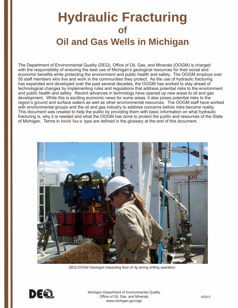
DEQ-OOGM Geologist inspecting floor of rig during drilling operation.
What is Hydraulic Fracturing? Hydraulic fracturing is part of the completion of some oil or natural gas wells after they are drilled. Hydraulic fracturing involves pumping water at high pressure to create fractures in reservoir rock that allow the oil or natural gas to flow more freely to the well bore. Proppants, usually silica sand, are added to the water to hold the fractures open once they are created. Small concentrations of chemicals are added to improve the effectiveness of the fracture job.
Recently, hydraulic fracturing and horizontal drilling have been utilized, to increase exposure of more reservoir rock formation to the well bore to maximize production. Horizontal drilling has been used commercially since the 1980s but has not been widely applied until recent years. Hydraulic fracturing has been utilized throughout the United States for more than 60 years and allows production in tight geologic formations which would otherwise not yield economical amounts of oil and natural gas. In the past 60 years significant advancements of the technology have occurred in such areas proppant development, fluid advances, modeling and simulation, and horizontal well integration. After completing a hydraulic fracture treatment the fracturing fluid begins to flow back through the well casing to the wellhead. Typically, 25 to 75 percent of the hydraulic fracturing fluid is recovered as “flowback” water within a few weeks or months after hydraulic fracturing. The rest remains in the oil and gas-bearing formation or is recovered over time along with the oil and gas that is produced.
Hydraulic Fracturing in MichiganMichigan has comprehensive laws and rules , enforced by the DEQ, that regulate hydraulic fracturing as well as every other aspect of oil and gas drilling and production. The DEQ works to consider the risks of hydraulic fracturing and to institute regulations that minimize those risks. In Michigan, since 1952, when the first hydraulic fracture stimulation was performed in Michigan, more than 12,000 wells have been hydraulically fractured. Most of these are Antrim Shale Formation gas wells in the northern Lower Peninsula. Hydraulic fracturing procedures may take one to fifteen days depending on the length of the interval to be treated. OOGM staff inspect the sites regularly during drilling and completion activities. Recent interest in horizontally drilling and/or hydraulically fracturing formations has focused on the Utica-Collingwood in Northern Michigan, the A1 Carbonate in Mid and West Michigan, and the Black River (Van Wert zone) in Southern Michigan. The formations are more than 3,000 feet deep (4,000 to 10,000 feet below ground surface) and due to the long lateral lengths (up to 2 miles) are expected to require significant volumes of fluids for hydraulic fracturing. In response, the Supervisor of Wells Instruction 1-2011 was issued, which improves environmental protection measures and fosters greater transparency. The Instruction applies to high volume hydraulic fracturing well completions. It sets standards for water withdrawal evaluation; monitoring and reporting of fracturing pressures and rates; providing information on chemical additives; and reporting of flowback water.
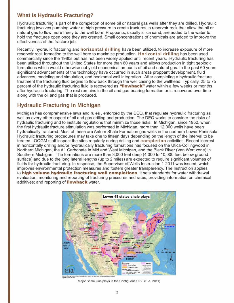
Major Shale Gas plays in the Contiguous U.S., (EIA, 2011)
2
Freshwater Pit
Flare
Company Man Trailers
Wellhead
Steel tanks containing produced water
Truck loading produced water for transport todisposal
Processing &separation equipment
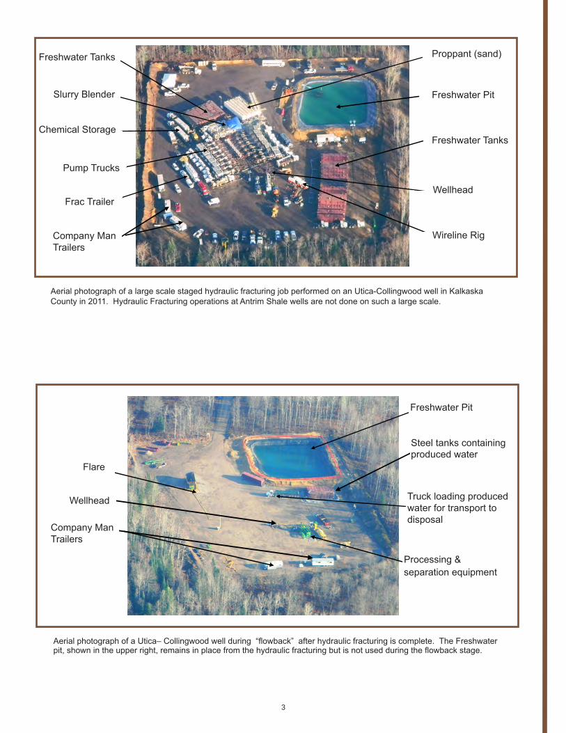
Aerial photograph of a Utica– Collingwood well during “flowback” after hydraulic fracturing is complete. The Freshwater pit, shown in the upper right, remains in place from the hydraulic fracturing but is not used during the flowback stage.
Proppant (sand)
Freshwater Pit
Freshwater Tanks
Wellhead
Freshwater Tanks
Wireline Rig
Slurry Blender
Chemical Storage
Pump Trucks
Frac Trailer
Company Man Trailers
Aerial photograph of a large scale staged hydraulic fracturing job performed on an Utica-Collingwood well in Kalkaska County in 2011. Hydraulic Fracturing operations at Antrim Shale wells are not done on such a large scale.
3
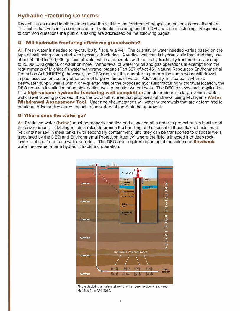
Hydraulic Fracturing Stages
Figure depicting a horizontal well that has been hydraulic fractured, Modified from API, 2012.
Hydraulic Fracturing Concerns: Recent issues raised in other states have thrust it into the forefront of people’s attentions across the state. The public has voiced its concerns about hydraulic fracturing and the DEQ has been listening. Responses to common questions the public is asking are addressed on the following pages.
Q: Will hydraulic fracturing affect my groundwater? A: Fresh water is needed to hydraulically fracture a well. The quantity of water needed varies based on the type of well being completed with hydraulic fracturing. A vertical well that is hydraulically fractured may use about 50,000 to 100,000 gallons of water while a horizontal well that is hydraulically fractured may use up to 20,000,000 gallons of water or more. Withdrawal of water for oil and gas operations is exempt from the requirements of Michigan’s water withdrawal statute (Part 327 of Act 451 Natural Resources Environmental Protection Act (NREPA)); however, the DEQ requires the operator to perform the same water withdrawal impact assessment as any other user of large volumes of water. Additionally, in situations where a freshwater supply well is within one-quarter mile of the proposed hydraulic fracturing withdrawal location, the DEQ requires installation of an observation well to monitor water levels. The DEQ reviews each application for a high-volume hydraulic fracturing well completion and determines if a large-volume water withdrawal is being proposed. If so, the DEQ will screen that proposed withdrawal using Michigan’s Water Withdrawal Assessment Tool. Under no circumstances will water withdrawals that are determined to create an Adverse Resource Impact to the waters of the State be approved.
Q: Where does the water go? A: Produced water (brine) must be properly handled and disposed of in order to protect public health and the environment. In Michigan, strict rules determine the handling and disposal of these fluids: fluids must be containerized in steel tanks (with secondary containment) until they can be transported to disposal wells (regulated by the DEQ and Environmental Protection Agency) where the fluid is injected into deep rock layers isolated from fresh water supplies. The DEQ also requires reporting of the volume of flowback water recovered after a hydraulic fracturing operation.
4
Q: What chemicals are used in Hydraulic Fracturing?A: The hydraulic fracturing fluid is generally composed of approximately 99.5% fresh water and sand and 0.5% chemical additives including friction reducers, biocides, stabilizers, acids, and compounds that increase the viscosity of the fluid. Like many household cleaners and solvents, some of the chemical additives used in hydraulic fracturing can have adverse health or environmental impacts if they are not properly handled. Oil and gas operators are required to provide to the DEQ copies of all Material Safety Data Sheets (MSDSs) for additives used in high volume hydraulic fracturing well completions. The MSDSs include information on physical characteristics, toxicity, health effects, first aid, reactivity, storage, disposal, protective equipment, and spill response. The DEQ posts the MSDSs on the Department’s web site for public review. While the details on some of the chemical compounds used in hydraulic fracturing are exempted from disclosure on the MSDSs under federal law, the MSDSs will provide enough information for the DEQ to track and monitor spills. More information about chemicals used in hydraulic fracturing can be found at Fracfocus.org.
Q: What if there is a spill? A: Surface spills of chemical additives or flowback water can have adverse environmental or public health impacts. Michigan requires secondary containment under tanks and other areas where spills are most likely to occur. If a spill does occur, it must be reported immediately to the DEQ, and cleaned up according to strict legal requirements identified in Part 201 of Act 451 (NREPA).
What’s in Fracturing Fluid?What’s in Fracking Fluid?
5
Q: Will my groundwater become contaminated?
A: A major public concern surrounding oil and natural gas development and particularly hydraulic fracturing is the migration of gas or other fluids out of the reservoir and into fresh water aquifers. In other states where migration of gas into freshwater aquifers has occurred, it has been the result of improper well construction or well construction problems not from hydraulic fracturing itself. The installation of steel pipe (“casing”) encased in cement is critical to preventing migration of gas or fluids. Michigan has strong regulations that require each oil and gas well to have a casing and cementing plan that will contain gas and other fluids within the well bore and the formation. Surface casing must be set a minimum of 100 feet into competent bedrock and at least 100 feet below any fresh water zones, this casing is cemented from the base to the ground surface. For most deeper wells, and intermediate casing string is set and cemented for added protection. Before fracturing or other completion operations can take place, a production casing must be set to the depth of the target reservoir and cemented in place. Geology varies across the state; therefore, every casing and sealing plan is thoroughly reviewed for site specific geologic characteristics. Additional strings of casing or revisions to the casing and sealing plan may be required by the DEQ to ensure that the plan will prevent migration of gas or fluids.
COLDWATER SHALE
ANTRIM SHALE
TRAVERSE LIMESTONE
DUNDEE
DETROIT RIVER ANYHDRITE AND SALT
AMHERSTBERG/SYLVANIA/BOIS BLANC
BASS ISLAND
SALINA SALTS/SHALES
A-2 CARBONATE & EVAPORATE/A-1 CARBONATE & EVAPORATE/POTASSIUM SALT
NIAGARAN/BURNT BLUFF/CABOT HEAD
CINCINNATIAN
UTICA-COLLINGWOOD
GROUND SURFACE
1,000'
2,000'
3,000'
4,000'
5,000'
6,000'
7,000'
8,000'
9,000'
STATE EXCELSIOR 1-25 HD1OLIVER TOWNSHIP, KALKASKA COUNTYTRUE VERTICAL DEPTH = 8,943MEASURED DEPTH = 16,890
EXAMPLE UTICA-COLLINGWOOD HORIZONTAL HYDRAULICALLY FRACTURED COMPLETED WELL DESIGN
GLACIAL DRIFTFRESHWATER AQUIFER
CASING STRINGS:
20'' CONDUCTOR SET AT 97 FEET
13-3/8'' SURFACE STRING SET AT 1,142 FEET. CEMENTED TO SURFACE
9-5/8'' INTERMEDIATE STRING SET AT 5,023 FEET. CEMENTED TO 3,100 FEET.
7'' LINER HUNG AT 4,740 FEET AND SET AT 9,101 FEET. CEMENTED TO 6,580 FEET
4.5'' PRODUCTION STRING TO TOTAL DEPTH. CEMENTED TO 7,700 FEET.
FRESHWATER AQUIFERFRESHWATER AQUIFER
FRESHWATER AQUIFER
SURFACE CASINGSET ATLEAST100 FEETBELOWAQUIFER
MU
LTIPLE IM
PE
RV
IOU
S LAYER
S A
ND
CO
NFIN
ING
FOR
MATIO
NS
6
Glossary
Aquifer: Sediment or rock formation that is contains water and porous and permeable enough to transmit water to wells and springs.
Brine: All nonpotable water resulting, obtained, or produced fromthe exploration, drilling or production of oil or gas, or both.
Casing: Heavy steel pipe place in an openhole and cemented into place. Casing is designed to withstand high pressures, large tensile loads and resist chemical reaction and corrosion. A casing string refers to a series of connected segments of casing or pipe that serves to prevent the hole from caving, keep the fluids inside the casing string from migrating to porous formations, prevents unwanted fluids from entering the hole, and protects fresh water aquifers.
Completion: Equipment and procedures used to bring a wellbore into production and enhance productivity after a well has been drilled, cased and sealed.
High volume hydraulic fracturing well completion: A well completion operation that is intended to use a total of more than 100,000 gallons of hydraulic fracturing fluid.
Horizontal Drilling: Deviation of a wellbore from vertical toward a horizontal inclination in order to intersect targeted fractures and/or maximize contact with a productive formation.
Large Volume Water Withdrawal: A water withdrawal intended to produce a cumulative total of over 100,000 gallons of water per day when averaged over a consecutive 30-day period. Use of surface water is prohibited for activities regulated under Part 615.
Flowback Water: Flowback water is a mix of fracturing fluids and native water from the formation itself (often termed “produced water”) that contains salts and other dissolved constituents. These fluids come to the surface through casing after the well has been completed.
Reservoir: A geological formation that contains economically producible quantities of oil and/or gas.
Secondary containment: A bermed plastic lining or other physical barrier that is used to contain primary containers and designed to catch spilled materials from the primary container. Secondary containment provides redundancy to primary containers, easing clean-up and protecting the environment.
Water Withdrawal Assessment Tool (WWAT): A computer program designed to estimate the likely ecological impact of a proposed water withdrawal on nearby streams and rivers. The WWAT considers the geographic variations in Michigan’s streams, geology, precipitation and fish community types to formulate mathematical models of stream flow, groundwater characteristics, and fish ecology. Stream flow models are used in combination with groundwater models to estimate how much a well will reduce the flow in nearby streams and to assess any impact to the types and abundance of fish that live there, serving as indicators to health of the overall stream ecosystem. (www.miwwat.org).
Photograph of a Utica–Collingwood well being drilled in Kalkaska County.
7
More Information / Contact UsGo to our homepage at www.michigan.gov/ogs and click on “hydraulic fracturing” to find Material Safety Data Sheets for the additives used in hydraulic fracturing completions, hydraulic fracturing presentations, current maps, regulations, Supervisor of Wells Instruction 1-2011 listing of wells and much more.
Still have questions? Contact the DEQ-OOGM at: Michigan DEQ, Office of Oil, Gas, and Minerals, P.O. Box 30256, Lansing, MI 48909-7756.
To report an environmental emergency situation, call our 24-hour Pollution Emergency Alerting System (PEAS) at 1-800-292-4706.
References:GWPC (Ground Water Protection Council) & ALL Consulting, 2009. Modern shale gas development in the US: A primer. Contract DE-FG26-04NT15455. Washington, DC: US Department of Energy, Office of Fossil Energy and National Energy Technology Laboratory. Accessed April 2012, from http://www.all-llc.com/publicdownloads/ShaleGasPrimer2009.pdfEIA, 2011. Shale Gas and Oil Plays, Lower 48 States. Digital image accessed April 2012. http://www.eia.gov/oil_gas/rpd/shale_gas.jpg
API, 2012. American Petroleum Institute, Shale Energy: 10 Points Everyone Should Know, March 2012. Digital image Accessed April 2012 http://www.api.org/~/media/Files/Policy/Exploration/HYDRAULIC_FRACT_ILLUSTRATION_121609.ashx
0 4020 Miles
1:500,000
5/15/2008
K E N TK E N T
D E L T AD E L T A
B A YB A Y
H U R O NH U R O N
L A K EL A K E
S A N I L A CS A N I L A C
I O N I AI O N I A
C A S SC A S S
O A K L A N DO A K L A N D
M A C K I N A CM A C K I N A C
C H I P P E W AC H I P P E W A
W A Y N EW A Y N E
A L L E G A NA L L E G A N
I O S C OI O S C O
E A T O NE A T O N
C L A R EC L A R E
S A G I N A WS A G I N A W
T U S C O L AT U S C O L A
N E W A Y G ON E W A Y G O
B A R R YB A R R Y
A L C O N AA L C O N A
L A P E E RL A P E E R
L E N A W E EL E N A W E E
J A C K S O NJ A C K S O N
A L P E N AA L P E N A
C A L H O U NC A L H O U N
S T. C L A I RS T. C L A I R
M A S O NM A S O N
O T T A W AO T T A W A
I N G H A MI N G H A M
E M M E TE M M E T
A N T R I MA N T R I M
G E N E S E EG E N E S E E
O S C O D AO S C O D A
O C E A N AO C E A N A
C L I N T O NC L I N T O N
O G E M A WO G E M A W
B E R R I E NB E R R I E N
G R A T I O TG R A T I O T
M O N R O EM O N R O E
M O N T C A L MM O N T C A L M
C H E B O Y G A NC H E B O Y G A N
O T S E G OO T S E G O
B R A N C HB R A N C H
S C H O O L C R A F TS C H O O L C R A F T
O S C E O L AO S C E O L A
M E C O S T AM E C O S T A I S A B E L L AI S A B E L L A M I D L A N DM I D L A N D
W E X F O R DW E X F O R D
W A S H T E N A WW A S H T E N A W
M A C O M BM A C O M B
G L A D W I NG L A D W I N
H I L L S D A L EH I L L S D A L E
K A L K A S K AK A L K A S K A
M A N I S T E EM A N I S T E E
V A N B U R E NV A N B U R E N
C R A W F O R DC R A W F O R D
M I S S A U K E EM I S S A U K E E
B E N Z I EB E N Z I E
L I V I N G S T O NL I V I N G S T O N
K A L A M A Z O OK A L A M A Z O O
M U S K E G O NM U S K E G O N
P R E S Q U E I S L EP R E S Q U E I S L E
A R E N A CA R E N A C
R O S C O M M O NR O S C O M M O N
S T. J O S E P HS T. J O S E P H
S H I A W A S S E ES H I A W A S S E E
A L G E RA L G E R
M O N T M O R E N C YM O N T M O R E N C Y
L E E L A N A UL E E L A N A U
L U C EL U C E
C H A R L E V O I XC H A R L E V O I X
G R A N D T R A V E R S EG R A N D T R A V E R S E