105
,- R • •• / I Hydraulic Institute Engineering Data Book First Edition

,- R
• ••
/
I
Hydraulic InstituteEngineering Data Book
FirstEdition

Cedar Falls, Iowa
Oakland. California
4546474849-74
4344
83,6485-979899-102
1314
56
7,69101112
15, 16171819
23-3133353739404142
7576777679608162
103,104
105,106
117
107-114115116
ItlE-3ItlE-4t11E-5
SECTION I-PREFACE .
SECTION II-CHARACTERISTICSOF FLUIDSIIA. WATER
IIA-l Properties of Water at Various Temperatures .IIA-2 Temperature vs Specific Gravity for Water .
lIB. OTHER FLUIDSIIB-l Degrees A.P,1. vs Specific Gravity for OilIIB-2 Specific Gravities vs Degrees Baume _ _ .IIB·3 Solids and Slurries ....................................•... _.IIB-4 Vapor Pressure-Liquid H2 ••••...••....••••.
IIB-S Vapor Pressure of Helium. . .... _...IIB-6 Vapor Pressure-Various Liquids
Chart 1 -600 to 240°F .Chart 2 -1800 to 60°F .
IIC. VISCOSITYIIC-l Definitions and Methods of Measurement., .....•.IlC-2 Viscosity Blending Chart .IIC-3 Viscosity Conversion Table .IIC-4 Viscosity Conversion Table
Table of Contents
SECTION III-FLUID FLOWInA. GENERAL
IJlA-l Fluid Flow-General .IIIA-l Friction Factors for Asphalt-Dipped Cast Iron Pipe .IIIA-2 Friction Factors for Steel or Wrought Iron Pipe .IIIA-3 Friction Factors for any kind and Size of Pipe1I1A-4 Relative Roughness Factors for New Clean Pipes .I1IA-S Kinematic Viscosity and Reynolds Number Chart .IIIA-6 Installation for Example No.1 .IIIA-7 Installation for Example No.2 ............................•.
IIIB. FRICTION LOSS-WATERIIIB-1 Friction Loss-Water.IIIB-l Installation for Example NO.3IIIB-2 Friction Loss for Water in Feet per Foot of Stainless Steel Tubing
and in Feet for Sanitary Fitti ngs .1118-3 Friction Losses in Deep Well Vertical Turbine Pump Columns and Discharge Heads1118-3 (a) Friction Loss Chart for Standard Pipe Column .1118-3 (b) Head Loss in Discharge Heads .IIIB-4 Friction Loss for Water in Feet per 100 Feet of PipeIIIB-S Resistance Coefficients for Valves and Fittings
Table 32 (a) ...........................................•.Table 32 (b) . . ......•.Table 32 (e) .............................................................•.Table 33-Resistance Coefficients for Fittings.
IIIB-SA Resistance Coefficients for 90 Degree Bends of Uniform Diameter.IIIB·58 Aesistance Coefficients for 8ends of Uniform Diameter and Smooth Surface.1118·6 Resistance Coefficients for Increasers and Diffusers1118-7 Resistance Coefficients for Reducers .
mc. OTHER FLUIDS(IIC Calculation of Friction Loss for any Fluid in Steel or Wrought Iron PipesIIIC-l thru IIIC-13 Friction Loss Modulus for 100 Feet of Pipe , .IIIC-14 Installation for Example No.4........... . .IIIC-15 Table 34-Friction Loss for Viscous Liquids ...............•.
IIID. FRICTION LOSS OF NOZZLES1110-1 Table 35-Theoretical Discharge of Nozzles in GPM .
IIIE. FRICTION LOSSOF PAPERSTOCKIIIE-l Friction of Paper Stock Suspensions in Pipes ..........................•.IIIE-2 Friction Loss of Paper Stock Suspensions in Schedule 40 Steel Pipe
(Table 36 thru 43) .Friction of Paper Stock Suspensions in Pipes (Table 44) .Friction of Paper Stock Suspensions in 90° Short Radius Elbows (Table 45) .Conversion of Tons of Stock per 24 Hours at Various Consistencies to GPM(Table 46) .
t 1 r i
Montebello. CaliformaCommerce, Georgia
Toccoa. GeorgiaMansfield. OhioFresno. California
Afton Pumps, Inc. Houston, TexasAllis-Chalmers Corporation Cincinnati, OhioAmpco Metal Division
Ampco-Pittsburgh Corporation Milwaukee. WisconsinA-S-H Pump Paoli, PennsylvaniaAurora Pump
Unit of General Signal North Aurora, IllinoisBarrett, Haentjens & Company Hazleton. PennsylvaniaBIF-A Unit of General Signal West Warwick, Rhode IslandBingham.WiIlamette Company Portland, OregonBuffalo Pumps Division
Buffalo Forge Company Buffalo, New YorkByron Jackson Pump Division
Borg-Warner Corporation Los Angeles, CaliforniaCarver Pump Company Muscatine. IowaCascade Pump Company Santa Fe Springs. CaliforniaCrane Deming Pumps Salem. OhioDean Brothers Pumps, Inc. Indianapolis. IndianaDelaval Turbine, Inc. Princeton. New JerseyDenver Equipment Division
Joy Manufacturing Company Colorado Springs, ColoradoDresser Industries. Inc.
Pacific Pump Division Huntington Park. CaliforniaThe Duriron Company, Inc. Dayton. OhioECa Pump Corporation South Plainfield. New JerseyEconomy Pump Corporation Cleveland, OnioFairbanks Morse Pump Division
Colt Industnes, Inc Kansas City. KansasFlygt Corporation Norwalk. ConnecticutFoster Pump Works, Inc. Westerly. Rhode IslandFrederick Iron & Steel, Inc. Frederick. MarylandFybroc Division-MetPro Corporation Hatfield. PennsylvaniaThe Galigher Company Salt lake City. UtahGaso Pumps. Inc. Tulsa. OklahomaGaulin Corporation Everett. MassachusettsGoulds Pumps, Inc. Seneca Fajls, New YorkGoyne Pump Company Ashland. PennsylvaniaHydr-O-Matic Pumps
A Division of Wylain, Inc, Ashland. OhioIngersoll-Rand Company Woodcliff lake, New JerseyIn Fluid Handling Division Skokie. IllinoisJacuzzi Brothers, Inc. little Rock, ArkansasJohnston Pump Company Glendora, CaliforniaKrogh Pump Company San Francisco, CalifornialaBour Pump Company Elkhart, IndianaLadish Company k ・ ョ ッ セ ィ 。 N WisconsinLawrence Pumps, Inc. lawrence. Massachusettslayne & Bowler, Inc. Memphis. TennesseeChas. S. lewis & Company, Inc. 51. louis. MissouriLFE Fluid Control Division
Eastern Midland Weinman Hamden. ConnecticutMorris Pumps, Inc. Baldwinsville, New YorkMoyno Pump Division
Robbins & Myers. Inc. Springfield. OhioNational Pump Company, Inc. Glendale. ArizonaOberdorter Foundries, Inc. Syracuse. New YorkPacific Pumping Company
Division of Baltimore Aircoil. IncPatterson Pump
Dubie-Clark CompanyPeabody Barnes, Inc.Peabody Floway, Jnc.Peerless Pump
Division of Indian HeadRoper Pump CompanyScot Pump Division
Ardox Corporation Mequon, WisconsinSundstrand Fluid Handling Arvada. ColoradoTaco, Inc. Cranston. Rhode IslandTait, Inc. Dayton, OhioThrush Products, Inc. Peru, IndianaTRW Reds Pump Company Bartlesville, OklahomaTuthill Corporation Oak Brook, IllinoisUnion Pump Company Battle Creek, MichiganUnited Centrifugal Pumps San Jose. CaliforniaValley Pump DivIsion of Valley Industries, Inc. Lubbock, TexasViking Pump Division
Houdaille Industries, Inc.Warren Pumps, Inc.
Subsidiary of Houdaille Industries. Inc. Warren. MassachusettsWaterous Company South St. Paul. MinnesotaWaukesha Foundry Division
Abex Corporation Waukesha. WisconsinWEMCa Division
Envirotech Corporation Sacramento. CaliforniaWestern Land Roller Company Hastings. NebraskaA. R. Wiltley & Sons, Inc. Denver, ColoradoWilson-Snyder Pumps
Oilwell Division ot U_ S. Steel Dallas, TexasWorthIngton Pump Corporation (USA) Harrison, New Jersey
List of Members-1978
© 1979 by Hydraulic Institute
1230 Keith Building
Cleveland, Ohio 44115
Printed in U.S.A.
Hydraulic Institute1230 Keith BuildingCleveland, Ohio 44115
,-lIlIlr _

132-134.. .. 135,136
121-127128129130130131
(a) To develop and publish standards for pumps.(b) To coliect and disseminate information of
value to its members and to the public.(c) To appear for its members before govern-
mental departments and agencies and otherbodies in regard to matters affecting the in-dustry.
(d) To promote a spirit of cooperation among itsmembers for the improved production. properuse, and increased distribution of pumps.
(e) To increase the amount and to improve thequality of pump service to the public.
(f) To support educational and research activities.(g) To promote the business interests of its mem-
bers but not to engage in business of the kindordinarily carried on for profit or to performparticular services for its members or individ-ual persons as distinguished from activitiesto improve the business conditions and lawfulinterests of all of its members."
as well as the interests of the public in such mat-ters as are involved in manufacturing, engineer-ing, safety, transportation, and other problems ofthe industry, and to this end, among other things:
Preface
Of parallel interest is the following quotation fromArticle III. Membership, of the By-Laws of the Insti-tute:"Corporations, firms and individuals engagedwithin the United States in the manufacture ofpumps for sale in the open market, shall be eligibleto apply for membership in the Institute."
The Hydraulic Institute appreciates its responsi-bility in this connection and wili continue to wel-come ali suggestions of a constructive nature.Such recommendations wili be taken into accountin the development of future editions of the Hand-book.
This Handbook replaces the Hydraulic InstitutePipe Friction Manual and provides additional tech-nical information for those working with fluids.It is a companion to the Hydraulic Instllute Stan-dards, making available to the user a wealth ofdata for solving problems related to the pumpingand transfer of fluids.
The content is the result of recommendations ofmembers and friends of the Hydraulic Instituteand is based on the latest information available.Sources of additional material are listed in thebibliography.
Origin
The Hydraulic Institute came into being on April18-19, 1917, when sixteen manufacturers of in-dustrial pumps met and formed The HydraulicSociety. In 1933 the Society was re-organized andthe name changed to the Hydraulic Institute.
In 1917, when the Society was formed, the pumpindustry was faced with an urgent need to solve anumber of engineering problems brought aboutby the production needs of World War I. Today.while the activity has grown manifold, engineeringis stili the basic interest. The most important mani-festations of this interest appear in the develop-ment of standards, in engineering conferences,in sponsorship of cooperative research projects,and in cooperation with other engineering organ-izations.
Purpose and Aims
The purpose and aims of the Institute are best ex-pressed in the following quotation taken from Arti-cle II of the By-Laws of the Institute:"The Objects of the Institute are: To promote andfurther the interests of manufacturers of pumps.
SectionI
203
192192193193194194,195195196196196
197
198
199,200
201
191191
153154
155-161162·164165166,167168-173174,175176,177178
..... 179180181.182183-186187, 188
SECTION VI-BIBLIOGRAPHYVI BIBLIOGRAPHY .
SECTION V-USEFUL INFORMATIONVA. CONVERSION TABLES
VA-l Temperature..... . .VA-2 Acceleration of Gravity . .•.................•...
VA-3 Physical DimensionsTable A-Length. . ............•.........•.........•........•...........Table B-Area ....•....•..•....••.. . .....•...............•..Table C-Volume . . .•...•.....•........•............••..•....•....
VA-4 Velocity......... ......•.....•. ...•. .. . ..•...•..•.....••......VA-5 Capacity. . .......•........VA-6 Mass, Weight and Force .....••.. · .......•••...•... . ..........•....VA-7 Density. . . . . . . . . . . . . . . • • • . . . • • . . . .........•......VA-8 Pressure......... .........••..••.....•....... • ..•..........VA-9 Energy, Work, Heat.... ..... . . .....•....•.VA-10 Power. . .......•..............
VB. VOLUME OF ROUND AND RECTANGULAR TANKS .VC. BAROMETRIC PRESSURE-EFFECT OF ALTITUDE .VD. CIRCUMFERENCE AND AREAS OF CIRCLES.. .. .VE. MECHANICAL FRICTION IN LINE SHAFTS .
SECTION IV-CHARACTERISTICS OF PIPING MATERIALSIVA. STEEL PIPE
IVA-' Pipe Dimensions; Wrought Steel and Stainless Steel.IVA-2 Specifications for Wrought Steel and Stainless Steel Pipe.IVA-3 API Casing List. . - ..IVA-4 API Plain-End Liner List.IVA·5 API Tubing List.... . . ...••.....•....•.IYA-6 API Drill Pipe List .
IVB. IRON PIPEIYB-1 Cast Iron Pipe Dimensions ..IVB-2 Ductile Iron Pipe Dimensions.
IVC. NON-FERROUS PIPE AND TUBINGIve-1 Aluminum Alloy Seamless Pipe and Extruded Pipe. 137.138lYC-2 Aluminum Alloy Pipe-Oil and Gas Transmission and Distribution Piping Systems 139,140IVC-3 Aluminum Coiled Tubing-Instrument and Oil Lines, Refrigeration Services. 141IYC-4 Seamless Copper and Seamless Red Brass Pipe...... 142IYC-S Threadless Copper Pipe 143IVC-6 Seamless Copper Water Tube.... 144IVG-7 Wrought Seamless Copper and Copper Alloy Tube ....••....•..•...... 145-148IVG-8 Copper Capillary Tube, Hard-Drawn ........•..•........ 149IVC-9 Seamless Copper-Nickel Pipe and Tube......... .........•...•...•.. 150-152
IVD. PLASTIC LINE PIPEIVD-l Thermosetting Resin Line Pipe, Glass Fiber Reinforced.IVD-2 Thermoplastic Line Pipe (PVC) . . .
IVE. FLANGESIVE.l Steel Pipe Flanges and Flanged Fittings-lSD, 300, 400, 600, 900, 1500 and 2500 lbIVE-2 Steel Flange Facings-lSD, 300, 400 lb and Higher. Lapped JointsIVE-3 Dimensions of Facings (Other than Ring Joints), All Pressures.IVE·4 Dimensions of Ring Joint FacingsIVE-5 API Type 68 Flanges-2000, 3000, 5000 PSI.IVE-6 API Type 68X Integral Flanges for 5,000.10,000 and 15.000 PSI ...........•..IVE-7 API Type 6BX Welding Neck Flanges for 10,000 and 15,000 PSIIVE-8 Welding Ends for Welding Neck Flanges.IVE·9 API Type 6BX Blind and Test Flanges for 10,000 and 15,000 PSI.IVE-l0 Test and Gage Connections for 15,000 Lb. Christmas TreesIVE-11 API Type 66 Threaded Flange, Counterbore Dimensions ....IVE-12 Cast Iron Flange Dimensions and Drilling Templates-25, 125, 250 and 800 PSI ...IVE-13 Assembly of Steel RF Flanges to Cast Iron, Brass, Bronze or Stainless Steel
II

6
SectiooR
1 T1 r セ
Characteristicsof Fluids
Characteristic •UI
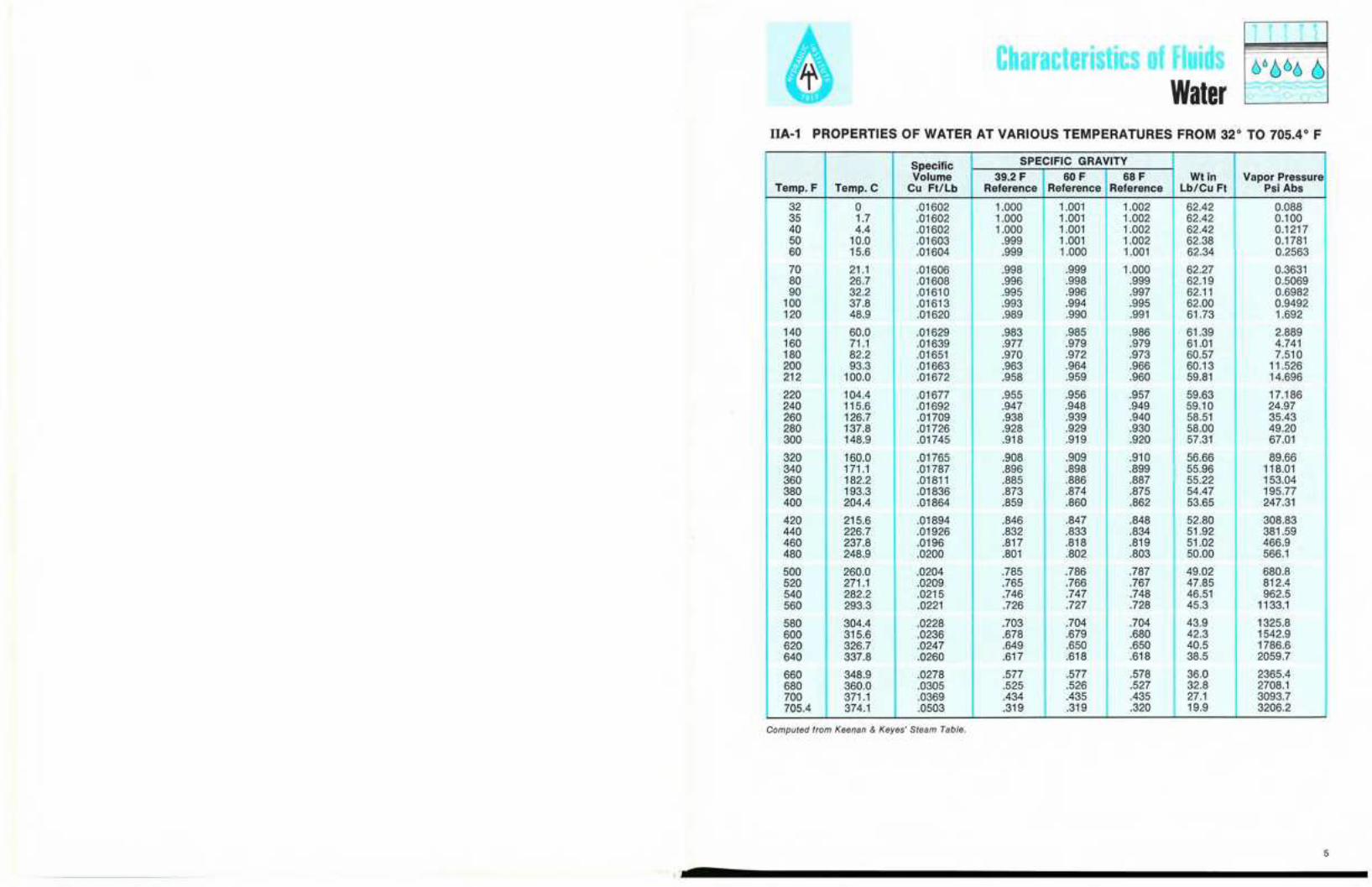
WaterIIA-1 PROPERTIES OF WATER AT VARIOUS TEMPERATURES FROM 32° TO 705.4° F
Specific SPECIFIC GRAVITYVolume 39.2 F 60 F 68 F WI in Vapor Pressure
Temp. F Temp. C Cu FI/Lb Reference Reference Reference Lb/Cu FI Psi Abs
32 0 .01602 1.000 1.001 1.002 62.42 0.08835 1.7 .01602 1.000 1.001 1.002 62.42 0.10040 4.4 .01602 1.000 1.001 1.002 62.42 0.121750 10.0 .01603 .999 1.001 1.002 62.38 0.178160 15.6 .01604 .999 1.000 1.001 62.34 0.2563
70 21.1 .01606 .998 .999 1.000 62.27 0.363180 26.7 .01608 .996 .998 .999 62.19 0.506990 32.2 .01610 .995 .996 .997 62.11 0.6982
100 37.8 .01613 .993 .994 .995 62.00 0.9492120 48.9 .01620 .989 .990 .991 61.73 1.692
140 60.0 .01629 .983 .985 .986 61.39 2.889160 71.1 .01639 .977 .979 .979 61.01 4.741180 82.2 .01651 .970 .972 .973 60.57 7.510200 93.3 .01663 .963 .964 .966 60.13 11.526212 100.0 .01672 .958 .959 .960 59.81 14.696
220 104.4 .01677 .955 .956 .957 59.63 17.186240 115.6 .01692 .947 .948 .949 59.10 24.97260 126.7 .01709 .938 .939 .940 58.51 35.43280 137.8 .01726 .928 .929 .930 58.00 49.20300 148.9 .01745 .918 .919 .920 57.31 67.01
320 160.0 .01765 .908 .909 .910 56.66 89.66340 171.1 .01787 .896 .898 .899 55.96 118.01360 182.2 .01811 .885 .886 .887 55.22 153.04380 193.3 .01836 .873 .874 .875 54.47 195.77400 204.4 .01864 .859 .860 .862 53.65 247.31
420 215.6 .01894 .846 .847 .848 52.80 308.83440 226.7 .01926 .832 .833 .834 51.92 381.59460 237.8 .0196 .817 .818 .819 51.02 466.9480 248.9 .0200 .801 .802 .803 50.00 566.1
500 260.0 .0204 .785 .786 .787 49.02 680.8520 271.1 .0209 .765 .766 .767 47.85 812.4540 282.2 .0215 .746 .747 .748 46.51 962.5560 293.3 .0221 .726 .727 .728 45.3 1133.1
580 304.4 .0228 .703 .704 .704 43.9 1325.8600 315.6 .0236 .678 .679 .680 42.3 1542.9620 326.7 .0247 .649 .650 .650 40.5 1786.6640 337.8 .0260 .617 .618 .618 38.5 2059.7
660 348.9 .0278 .577 .577 .578 36.0 2365.4680 360.0 .0305 .525 .526 .527 32.8 2708.1700 371.1 .0369 .434 .435 .435 27.1 3093.7705.4 374.1 .0503 .319 .319 .320 19.9 3206.2
Computed from Keenan & Keyes' Steam Table.
5

Characteristics of FluidsWater
1r 1r i(:}6 666
I--" セ セ
10 0 a
Characteristics of FluidsOther Fluids
1r 1r i
7(cont'd)
D = Density or Specific Gravity of mixturem = Proportion of oil dr densityn = Proportion of oil of d, densityd, = Specific Gravity of m oild l :::: Specific Gravity of n oil
gallon of water at 60" Fahrenheit in air is 8.32828pounds .
To determine the resulting gravity by mixing oilsof different gravities:
D:::; md , + nd,m+n
118-1 DEGREES A.P.1. VS SPECIFIC GRAVITY FOR OIL
The relation of Degrees A.P.1. to Specific Gravity(G) is expressed by the following formula;
141.5DegreesA.P.1. = ---cr- -131.5,
G = 141.5131.5+ DegreesA.P.1.
The following tables are based on the weight of1 gallon (U.S.) of oil with a volume of 231 cubicinches at 60 degrees Fahrenheit in air at 760 m.m.pressure and 50% humidity. Assumed weight of 1
Reprinted with permission from the Allis-Chalmers Corporation.
Soecific Specific Specific Specific Specific Specific Specific SpecificDegrees gravity at Degrees gravity at Degrees gravity at Degrees gravity at Degrees gravity at Degrees gravity at Degrees gravity at Degrees gravity atA.P.1. Goo·GO°F. A.P.1. GO°·60oF. A.P.1. SO°·GO°F. A.P.1. 60o·GooF. A.P.I. Goo·60oF. A.P.I. 60o.60oF. A.P.1. 60°_GOoF. A.P.1. 60°_60°F.
10.0 1.0000 15.0 .9659 20.0 .9340 25.0 .9042 30.0 .8762 35.0 .8498 40.0 .8251 45.0 .801710.1 .9993 15.1 .9652 20.1 .9334 25.1 .9036 30.1 .8756 35.1 .8493 40.1 .8246 45.1 .801210.2 .9986. 15.2 .9646 20.2 .9328 25.2 .9030 30.2 .8751 35.2 .8488 40.2 .8241 45.2 .800810.3 .9979 15.3 .9639 20.3 .9321 25.3 .9024 30.3 .8745 35.3 .8483 40.3 .8236 45.3 .800310.4 .9972 15.4 .9632 20.4 .9315 25.4 .9018 30.4 .8740 35.4 .8478 40.4 .8232 45.4 .7999
10.5 .9965 15.5 .9626 20.5 .9309 25.5 .9013 30.5 .8735 35.5 .8473 40.5 .8227 45.5 .799410.6 .9958 15.6 .9619 20.6 .9303 25.6 .9007 30.6 .8729 35.6 .8468 40.6 .8222 45.6 .799010.7 .9951 15.7 .9613 20.7 .9297 25.7 .9001 30.7 .8724 35.7 .8463 40.7 .8217 45.7 .798510.8 .9944 15.8 .9606 20.8 .9291 25.8 .8996 30.8 .8718 35.8 .8458 40.8 .8212 45.8 .798110.9 .9937 15.9 .9600 20.9 .9285 25.9 .8990 30.9 .8713 35.9 .8453 40.9 .8208 45.9 .7976
11.0 .9930 16.0 .9593 21.0 .9279 26.0 .8984 31.0 .8708 36.0 .8448 41.0 .8203 46.0 .797211.1 .9923 16.1 .9587 21.1 .9273 26.1 .8978 31.1 .8702 36.1 .8443 41.1 .8198 46.1 .796711.2 .9916 16.2 .9580 21.2 .9267 26.2 .8973 31.2 .8697 36.2 .8438 41.2 .8193 46.2 .796311.3 .9909 16.3 .9574 21.3 .9260 26.3 .8967 31.3 .8692 36.3 .8433 41.3 .8189 46.3 .795811.4 .9902 16.4 .9567 21.4 .9254 26.4 .8961 31.4 .8686 36.4 .8428 41.4 .8184 46.4 .7954
11.5 .9895 16.5 .9561 21.5 .9248 26.5 .8956 31.5 .8681 36.5 .8423 41.5 .8179 46.5 .794911.6 .9888 16.6 .9554 21.6 .9242 26.6 .8950 31.6 .8676 36.6 .8418 41.6 .8174 46.6 .794511.7 .9881 16.7 .9548 21.7 .9236 26.7 .8944 31.7 .8670 36.7 .8413 41.7 .8170 46.7 .794111.8 .9874 16.8 .9541 21.8 .9230 26.8 .8939 31.8 .8665 36.8 .8408 41.8 .8165 46.8 .793611.9 .9868 16.9 .9535 21.9 .9224 26.9 .8933 31.9 .8660 36.9 .8403 41.9 .8160 46.9 .7932
12.0 .9861 17.0 .9529 22.0 .9218 27.0 .8927 32.0 .8654 37.0 .8398 42.0 .8155 47.0 .792712.1 .9854 17.1 .9522 22.1 .9212 27.1 .8922 32.1 .8649 37.1 .8393 42.1 .8151 47.1 .792312.2 .9847 17.2 .9516 22.2 .9206 27.2 .8916 32.2 .8644 37.2 .8388 42.2 .8146 47.2 .791812.3 .9840 17.3 .9509 22.3 .9200 27.3 .8911 32.3 .8639 37.3 .8383 42.3 .8142 47.3 .791412.4 .9833 17.4 .9503 22.4 .9194 27.4 .8905 32.4 .8633 37.4 .8378 42.4 .8137 47.4 .7909
12.5 .9826 17.5 .9497 22.5 .9188 27.5 .8899 32.5 .8628 37.5 .8373 42.5 .8132 47.5 .790512.6 .9820 17.6 .9490 22.6 .9182 27.6 .8894 32.6 .8623 37.6 .8368 42.6 .8128 47.6 .790112.7 .9813 17.7 .9484 22.7 .9176 27.7 .8888 32.7 .8618 37.7 .8363 42.7 .8123 47.7 .789612.8 .9806 17.8 .9478 22.8 .9170 27.8 .8883 32.8 .8612 37.8 .8358 42.8 .8118 47.8 .789212.9 .9799 17.9 .9471 22.9 .9165 27.9 .8877 32.9 .8607 37.9 .8353 42.9 .8114 47.9 .7887
13.0 .9792 18.0 .9465 23.0 .9159 28.0 .8871 33.0 .8602 38.0 .8348 43.0 .8109 48.0 .788313.1 .9786 18.1 .9459 23.1 .9153 28.1 .8866 33.1 .8597 38.1 .8343 43.1 .8104 48.1 .787913.2 .9779 18.2 .9452 23.2 .9147 28.2 .8860 33.2 .8591 38.2 .8338 43.2 .8100 48.2 .787413.3 .9772 18.3 .9446 23.3 .9141 28.3 .8855 33.3 .8586 38.3 .8333 43.3 .8095 48.3 .787013.4 .9765 18.4 .9440 23.4 .9135 28.4 .8849 33.4 .8581 38.4 .8328 43.4 .8090 48.4 .7865
13.5 .9759 18.5 .9433 23.5 .9129 28.5 .8844 33.5 .8576 38.5 .8324 43.5 .8086 48.5 .786113.6 .9752 18.6 .9427 23.6 .9123 28.6 .8838 33.6 .8571 38.6 .8319 43.6 .8081 48.6 .785713.7 .9745 18.7 .9421 23.7 .9117 28.7 .8833 33.7 .8565 38.7 .8314 43.7 .8076 48.7 .785213.8 .9738 18.8 .9415 23.8 .9111 28.8 .8827 33.8 .8560 38.8 .8309 43.8 .8072 48.8 .784813.9 .9732 18.9 .9408 23.9 .9106 28.9 .8822 33.9 .8555 38.9 .8304 43.9 .8067 48.9 .7844
14.0 .9725 19.0 .9402 24.0 .9100 29.0 .8816 34.0 .8550 39.0 .8299 44.0 .8063 49.0 .783914.1 .9718 19.1 .9396 24.1 .9094 29.1 .8811 34.1 .8545 39.1 .8294 44.1 .8058 49.1 .783514.2 .9712 19.2 .9390 24.2 .9088 29.2 .8805 34.2 .8540 39.2 .8289 44.2 .8054 49.2 .783114.3 .9705 19.3 .9383 24.3 .9082 29.3 .8800 34.3 .8534 39.3 .8285 44.3 .8049 49.3 .782614.4 .9698 19.4 .9377 24.4 .9076 29.4 .8794 34.4 .8529 39.4 .8280 44.4 .8044 49.4 .7822
14.5 .9692 19.5 .9371 24.5 .9071 29.5 .8789 34.5 .8524 39.5 .8275 44.5 .8040 49.5 .781814.6 .9685 19.6 .9365 24.6 .9065 29.6 .8783 34.6 .8519 39.6 .8270 44.6 .8035 49.6 .781314.7 .9679 19.7 .9358 24.7 .9059 29.7 .8778 34.7 .8514 39.7 .8265 44.7 .8031 49.7 .780914.8 .9672 19.8 .9352 24.8 .9053 29.8 .8772 34.8 .8509 39.8 .8260 44.8 .8026 49.8 .780514.9 .9665 19.9 .9346 24.9 .9047 29.9 .8767 34.9 .8504 39.9 .8256 44.9 .8022 49.9 .7800
Reprinted withpermission from theAllis-ChalmersCorporation.
...o
00
50
50
00
00
50
100
50
200
150
250
350 Wa:::;)
lia:W
300 D.:::;;WI-
o.86.88.90.96 .94 .92
SPECIFIC GRAVITY.981.00
6
r-- • - /'.- -,
./ 6
..,-/'
./ 5
,//
" 5/
/
" 4
V/ 4
/'V
I V./
,/
VV
./V
)(/
// -
/1
/ iI1/
I1.02
IIA-2 TEMPERATURE VS SPECIFIC GRAVITY FOR WATER
SPECIFIC GRAVITY.86 84 82 80 78 76 74 72 70 68 66 64 62 60 58 56
6

Other FluidsCaracteriI .
Other FluidsCharacteri
IIB-1 DEGREES A.P.r. VS SPECIFIC GRAVITY FOR OIL (Cont'd)
54.5 .7608 61.0 .7351 67.5 .7111 74.0 .6886 80.5 .6675 87.0 .6476 93.5 .6289 100.0 .611254.6 .7603 61.1 .7347 67.6 .7107 74.1 .6882 80.6 .6671 87.1 .6473 93.6 .628654.7 .7599 61.2 .7343 67.7 .7103 74.2 .6879 80.7 .6668 87.2 .6470 93.7 .628354.8 .7595 61.3 .7339 67.8 .7100 74.3 .6876 80.8 .6665 87.3 .6467 93.8 .628154.9 .7591 61.4 .7335 67.9 .7096 74.4 .6872 80.9 .6662 87.4 .6464 93.9 .6278
55.0 .7587 61.5 .7332 68.0 .7093 74.5 .6869 81.0 .6659 87.5 .6461 94.0 .627555.1 .7583 61.6 .7328 68.1 .7089 74.6 .6866 81.1 .6656 87.6 .6458 94.1 .627255.2 .7579 61.7 .7324 63.2 .7086 74.7 .6862 81.2 .6653 87.7 .6455 94.2 .626955.3 .7575 61.8 .7320 68.3 .7082 74.8 .6859 81.3 .6650 87.8 .6452 94.3 .626755.4 .7571 61.9 .7316 68.4 .7079 74.9 .6856 81.4 .6646 87.9 .6449 94.4 .6264
55.5 .7567 62.0 .7313 68.5 .7075 75.0 .6852 81.5 .6643 88.0 .6446 94.5 .626155.6 .7563 62.1 .7309 68.6 .7071 75.1 .6849 81.6 .6640 88.1 .6444 94.6 .625855.7 .7559 62.2 .7305 68.7 .7068 75.2 .6846 81.7 .6637 88.2 .6441 94.7 .625655.8 .7555 62.3 .7301 68.8 .7064 75.3 .6842 81.8 .6634 88.3 .6438 94.8 .625355.9 .7551 62.4 .7298 68.9 .7061 75.4 .6839 81.9 .6631 88.4 .6435 94.9 .6250
56.0 .7547 62.5 .7294 69.0 .7057 75.5 .6836 82.0 .6628 88.5 .6432 95.0 .624756.1 .7543 62.6 .7290 69.1 .7054 75.6 .6832 82.1 .6625 88.6 .6429 95.1 .624456.2 .7539 62.7 .7286 69.2 .7050 75.7 .6829 82.2 .6621 88.7 .6426 95.2 .624256.3 .7535 62.8 .7283 69.3 .7047 75.8 .6826 82.3 .6618 88.8 .6423 95.3 .623956.4 .7531 62.9 .7279 69.4 .7043 75.9 .6823 82.4 .6615 88.9 .6420 95.4 .6236
Specific SpecIfic Specllic Specific Specific Specific Specific SpecIficDegrees gravity at Degrees gravity at Degrees gravity at Degrees raVily at Degrees gravity at Degrees gravity at Degrees gravity at Degrees gravity at
A.P.1. Goo·GO°F. A.P.1. Goo·GooF. A.P.1. 60o·GooF. A.P.I. OO·GO°F. A.P.1. 60o·GooF. A.P.1. Gl)°.60oF. A.P.1. Goo·GooF. A.P.1. GOO·GOOF.
50.0 .7796 56.5 .7527 63.0 .7275 69.5 .7040 I 76.0 .6819 I 82.5 .6612 89.0 .6417 95.5 .623350.1 .7792 56.6 .7523 63.1 .7271 69.6 .7036 76.1 .6816 82.6 .6609 89.1 .6414 95.6 .623150.2 .7788 56.7 .7519 63.2 .7268 69.7 .7033 76.2 .6813 82.7 .6606 89.2 .6411 95.7 .622850.3 .7783 56.8 .7515 63.3 .7264 69.8 .7029 76.3 .6809 82.8 .6603 89.3 .6409 95.8 .622550.4 .7779 56.9 .7511 63.4 .7260 69.9 .7026 76.4 .6806 82.9 .6600 89.4 .6406 95.9 .6223
50.5 .7775 57.0 .7507 63.5 .7256 70.0 .7022 76.5 .6803 83.0 .6597 89.5 .6403 96.0 .622050.6 .7770 57.1 .7503 63.6 .7253 70.1 .7019 76.6 .6800 83.1 .6594 89.6 .6400 96.1 .621750.7 .7766 57.2 .7499 63.7 .7249 70.2 .7015 76.7 .6796 83.2 .6591 89.7 .6397 96.2 .621450.8 .7762 57.3 .7495 63.8 .7245 70.3 .7012 76.8 .6793 83.3 .6588 89.8 .6394 96.3 .621250.9 .7758 57.4 .7491 63.9 .7242 70.4 .7008 76.9 .6790 83.4 .6584 89.9 .6391 96.4 .6209
51.0 .7753 57.5 .7487 64.0 .7238 70.5 .7005 77.0 .6787 83.5 .6581 90.0 .6388 96.5 .620651.1 .7749 57.6 .7483 64.1 .7234 70.6 .7001 77.1 .6783 83.6 .6578 90.1 .6385 966 .620351.2 .7745 57.7 .7479 64.2 .7230 70.7 .6998 77.2 .6780 83.7 .6575 90.2 .6382 96.7 .620151.3 .7741 57.8 .7475 64.3 .7227 70.8 .6995 77.3 .6777 83.8 .6572 90.3 .6380 96.8 .619851.4 .7736 57.9 .7471 64.4 .7223 70.9 .6991 77.4 .6774 83.9 .6569 90.4 .6377 96.9 .6195
51.5 .7732 58.0 .7467 64.5 .7219 71.0 .6988 77.5 .6770 84.0 .6566 90.5 .6374 97.0 .619351.6 .7728 58.1 .7463 64.6 .7216 71.1 .6984 77.6 .6767 84.1 .6563 90.6 .6371 97.1 619051.7 .7724 58.2 .7459 64.7 .7212 71.2 .6981 77.7 .6764 84.2 .6560 90.7 .6368 97.2 .618751.8 .7720 58.3 .7455 64.8 .7208 71.3 .6977 77.8 .6761 84.3 .6557 90.8 .6365 97.3 .618451.9 .7715 58.4 .7451 64.9 .7205 71.4 .6974 77.9 .6757 84.4 .6554 90.9 .6362 97.4 .6182
52.0 .7711 58.5 .7447 65.0 .7201 71.5 .6970 78.0 .6754 84.5 .6551 91.0 .6360 97.5 .617952.1 .7707 58.6 .7443 65.1 .7197 71.6 .6967 78.1 .6751 84.6 .6548 91.1 .6357 97.6 .617652.2 .7703 58.7 .7440 65.2 .7194 71.7 .6964 78.2 .6748 84.7 .6545 91.2 .6354 97.7 .617452.3 .7699 58.8 .7436 65.3 .7190 71.8 .6960 78.3 .6745 84.8 .6542 91.3 .6351 97.8 .617152.4 .7694 58.9 .7432 65.4 .7186 71.9 .6957 78.4 .6741 84.9 .6539 91.4 .6348 97.9 .6168
52.5 .7690 59.0 .7428 65.5 .7183 72.0 .6953 78.5 .6738 85.0 .6536 91.5 .6345 98.0 .616652.6 .7686 59.1 .7424 65.6 .7179 72.1 .6950 78.6 .6735 85.1 .6533 91.6 .6342 98.1 .616352.7 .7682 59.2 .7420 65.7 .7175 72.2 .6946 78.7 .6732 85.2 .6530 91.7 .634 98.2 .616052.8 .7678 59.3 .7416 65.8 .7172 72.3 .6943 78.8 .6728 85.3 .6527 91.8 .6337 98.3 .615852.9 .7674 59.4 .7412 65.9 .7168 72.4 .6940 78.9 .6725 85.4 .6524 91.9 .6334 98.4 .6155
53.0 .766953.1 .766553.2 .766153.3 .765753.4 .7653
53.5 .764953.6 .764553.7 .764053.8 .763653.9 .7632
54.0 .762854.1 .762454.2 .762054.3 .7616544 7612
59.5 .740859.6 .740559.7 .740159.8 .739759.9 .7393
60.0 .738960.1 .738560.2 .738160.3 .737760.4 .7374
60.5 .737060.6 .736660.7 .736260.8 .7358609 7354
66.0 .716566.1 .716166.2 .715766.3 .715466.4 .7150
66.5 .714666.6 .714366.7 .713966.8 .713666.9 .7132
67.0 .712867.1 .712567.2 .712167.3 .7118674 7114
72.5 .693672.6 .693372.7 .692972.8 .692672.9 .6923
73.0 .691973.1 .691673.2 .691373.3 .690873.4 .6906
73.5 .690273.6 .689973.7 .689673.8 .6892739 6889
79.0 .672279.1 .671979.2 .671679.3 .671379.4 .6709
79.5 .670679.6 .670379.7 .670079.8 .669779.9 .6693
80.0 .669080.1 .668780.2 .668480.3 .6681804 6678
85.5 .652185.6 .651885.7 .651585.8 .651285.9 .6509
86.0 .650686.1 .650386.2 .650086.3 .649786.4 .6494
86.5 .649186.6 .648886.7 .648586.8 .6482869 6479
92.0 .633192.1 .632892.2 .632592.3 .632392.4 .6320
92.5 .631792.6 .631492.7 .631192.8 .630992.9 .6306
93.0 .630393.1 .630093.2 .629793.3 .6294934 6292
98.5 .615298.6 .615098.7 .614798.8 .614498.9 .6141
99.0 .613999.1 .613699.2 .613499.3 .613199.4 .6128
99.5 .612699.6 .612399.7 .612099.8 .6118999 6115
IIB-2 SPECIFIC GRAVITIES VS DEGREES BAUME
S T G .. t 60° F Corresponding to Degrees Baume for Liquids Lighter than Waterpeci IC ravilies a 600 ..,. . 600 F 140
Calculated from the formula, speci Ie gravIty 600 . 160 Deg. Be
IDegrees Specific Degrees Specific Degrees Specific Degrees Specific IDegrees Specific Degrees SpecificBaume gravity Baume gravity 8aume gravity 88ume gravity Baume gravity 8aume gravity
10 1.0000 25 0.9032 40 0.8235 55 0.7568 70 0.7000 85 0.651211 0.9929 26 0.8974 41 0.8187 56 0.7527 71 0.6965 88 0.648212 0.9859 27 0.8917 42 0.8140 57 0.7487 72 0.6931 87 0.845213 0.9790 28 0.8881 43 0.8092 58 0.7447 73 0.6897 88 0.642214 0.9722 29 0.8805 44 0.8046 59 0.7407 74 0.6863 89 0.8393
15 0.9655 30 0.8750 45 0.8000 80 0.7368 75 0.6829 90 0.636416 0.9589 31 0.8696 46 0.7955 61 0.7330 76 0.6796 91 0.833517 0.9524 32 0.8642 47 0.7910 82 0.7292 77 0.6763 92 0.630618 0.9459 33 0.8589 48 0.7865 63 0.7254 78 0.6731 93 0.627819 0.9396 34 0.8537 49 0.7821 64 0.7216 79 0.6699 94 0.6250
20 0.9333 35 0.8485 50 0.7778 65 0.7179 80 0.6667 95 0.622221 0.9272 36 0.8434 51 0.7735 66 0.7143 81 0.6635 96 0.619522 0.9211 37 0.8383 52 0.7692 67 0.7107 82 0.6604 97 0.616723 0.9150 38 0.8333 53 0.7650 68 0.7071 83 0.6573 98 0.614024 0.9091 39 0.8284 54 0.7609 69 0.7035 84 0.6542 99 0.6114
100 0.6087
T G .. t 60° F. Corresponding to Degrees Baume for Liquids Heavier than WaterSpeci IC ravilies a 600
'f . 60° F =145
Calculated from the formula, speci Ie gravlly 600 . 145 Deg. Be
Degrees Specific Degrees Specific IDegrees Specific Degrees Specific IDegrees Specific Degrees Specific
8aume gravity 8aume gravity 8aume gravity Baume gravity 8aume gravity 8aume gravity
0 1.0000 12 1.0902 24 1.1983 36 1.3303 48 1.4948 60 1.7059
1 1.0069 13 1.0985 25 1.2083 37 1.3426 49 1.5104 61 1.7262
2 1.0140 14 1.1069 26 1.2185 38 1.3551 50 1.5263 62 1.7470
3 1.0211 15 1.1154 27 1.2288 39 1.3679 51 1.5426 63 1.7683
4 1.0284 16 1.1240 28 1.2393 40 1.3810 52 1.5591 64 1.7901
5 1.0357 17 1.1328 29 1.2500 41 1.3942 53 1.5761 65 1.8125
6 1.0432 18 1.1417 30 1.2609 42 1.4078 54 1.5934 66 1.8354
7 1.0507 19 1.1508 31 1.2719 43 1.4216 55 1.6111 67 1.8590
8 1.0584 20 1.1600 32 1.2832 44 1.4356 56 1.6292 68 1.8831
9 1.0662 21 1.1694 33 1.2946 45 1.4500 57 1.6477 69 1.907910 1.0741 22 1.1789 34 1.3063 46 1.4646 58 1.6667 70 1.933311 1.0821 23 1.1885 35 1.3182 47 1.4796 59 1.6860
Reprinted with permission from the Allis-Chalmers Corporation .
8 9.

Characteristics of FluidsOther Fluids
1r 1r iCharacteristics of Fluids
Other Fluids118-3 -SOLIDS AND SLURRIES 118-4 VAPOR PRESSURE-LIQUID H2
Useful Formulas
Specific Gravity of Slurries
Number of U.S. Gallons Per Minute equivalent to 1 ton of dry solids per 24 hours in slurries of various solid-water ratios
% Solids Solid- SPECIFIC GRAVITY OF THE DRY SOLIDS IN THE SLURRYby Weight WaterRatio Slurry I., 2.2 2.' 2.7 2.' 2.' ,.. '.2 ,.. ,.. '.2 5.'
5 1,19.00 Sp. Gr. 1.02 1.03 1.03 1.03 1.03 1.03 1.03 1.04 1.04 1.04 1.04 1.04G.P.M.... 3.23 3.24 3.23 3.22 3.22 3.22 3.22 3.21 3.21 3.20 3.20 3.19
10 1, 9.00 Sp. Gr. 1.03 1.06 1.07 1.07 1.07 1.07 1.07 1.07 1.08 1.08 1.08 1.09G.P.M.... 1.62 1.57 1.56 1.56 1.55 1.56 1.55 1.55 1.55 1.54 1.54 1.53
15 1, 5.67 Sp. Gr. 1.05 1.09 1.10 1.10 1.11 1.11 1.11 1.12 1.12 1.12 1.13 1.14G.P.M ... 1.06 1.02 1.01 1.01 1.00 1.00 1.00 1.00 0.93 0.93 0.98 0.98
20 1 , 4.00 Sp. Gr. 1.06 1.12 1.14 1.14 1.15 1.15 1.15 1.16 1.16 1.17 1.18 1.19G.P.M.... 0.78 0.74 0.73 0.73 0.73 0.72 0.72 0.72 0.71 0.71 0.71 0.70
25 1 , 3.00 Sp. Gr. 1.03 1.16 1.18 1.19 1.19 1.20 1.20 1.21 1.21 1.23 1.24 1.25G.P.M.... 0.62 0.57 0.56 0.56 0.56 0.56 0.55 0.55 0.55 0.54 0.54 0.53
30 1 , 2.33 Sp.Gr. 1.09 1.20 1.23 1.23 1.24 1.25 1.25 1.26 1.27 1.28 1.30 1.32G.P.M.... 0.51 0.45 0.45 0.45 0.45 0.45 0.44 0.44 0.44 0.43 0.43 0.42
35 1, 1.86 Sp. Gr. 1.11 1.24 1.27 1.28 1.29 1.30 1.30 1.32 1.33 1.35 1.36 1.39G.P.M ... 0.43 0.39 0.37 0.37 0.37 0.37 0.37 0.36 0.36 0.35 0.35 0.34
40 1, 1.50 Sp. Gr. 1.13 1.28 1.33 1.34 1.35 1.36 1.36 1.38 1.39 1.42 1.44 1.47G.P.M.... 0.37 0.33 0.31 0.31 0.31 0.31 0.31 0.30 0.30 0.29 0.29 0.28
45 1 , 1.22 Sp. Gr. 1.15 1.33 1.38 1.40 1.41 1.42 1.43 1.45 1.47 1.50 1.52 1.56G.P.M.... 0.32 0.23 0.27 0.26 0.26 0.26 0.26 0.26 0.25 0.25 0.24 0.24
50 1, 1.00 Sp.Gr. 1.17 1.38 1.44 1.45 1.47 1.49 1.50 1.52 1.55 1.58 1.62 1.57G.P.M.... 0.23 0.24 0.23 0.23 0.23 0.22 0.22 0.22 0.22 0.21 0.21 0.20
55 1, 0.82 Sp. Gr. 1.19 1.43 1.51 1.53 1.55 1.57 1.58 1.61 1.63 1.68 1.73 1.79G.P.M.... 0.26 0.21 0.20 0.20 0.19 0.19 0.19 0.19 0.19 0.18 0.18 0.17
60 1, 0.67 Sp. Gr. 1.21 1.49 1.59 1.61 1.63 1.65 1.67 1.70 1.74 1.79 1.84 1.92G.P.M.... 0.23 0.19 0.18 0.17 0.17 0.17 0.17 0.16 0.16 0.16 0.15 0.14
65 1 , 0.54 Sp.Gr. 1.23 1.55 1.67 1.70 1.72 1.74 1.76 1.81 1.85 1.92 1.99 2.08G.P.M.... 0.21 0.17 0.15 0.15 0.15 0.15 0.15 0.14 0.14 0.13 0.13 0.12
70 1 ,0.43 Sp. Gr. 1.25 1.62 1.76 1.79 1.82 1.85 1.88 1.98 1.98 2.07 2.14 2.27G.P.M.... 0.19 0.15 0.14 0.13 0.13 0.13 0.13 0.12 0.12 0.12 0.11 0.10
J//
C-H, 0.21% 0, 99.79% P 1/Triple Point 13.8°K
1.02 PSIA
/Critical Point 33.2°K12.98 ATM191 PSIA /NBS RP 1932 IT-S Dia!lram
0
1/I
5 I
//
0 I
//
5 /, /
/0 /
//
/15 "
/ /--"--'
4
9
105
3
<iii 7D.
la:::lIJlIJlUJa: 6D.
UJI-::l..JoIJllD<
b. The formula for concentration of solids byweight. Cw• is:
C _ Weight of dry solidsW - Weight of dry solids + weight of liquid phase
S_ _ ---"1.:=2 _
m = =1.431 + NSUHセ
2.2
EXAMPLE 2: Carrying media other than water andsolids slurry. If the liquid is a brine with a specificgravity of 1.2 and the % solids by weight is 35%.with the solids having a specific gravity of 2.2.then:
where
a. The formula for specific gravity of a solids-liquids mixture or slurry. Sm. is:
S,,, = Specific gravity of mixture or slurrySI, = Specific gravity of liquid phaseS, = Specific gravity of solids phaseC" = Concentration of solids by weight
EXAMPLE 1: Water and solids slurry. If the water isliquid with a specific gravity of 1.0 and the % solidsby weight is 30%, with the soiids having a specificgravity of 2.7. then:
1Sm = =1.23
1+ NSPHセ -1)2.7
Reprinted with permission from the Allis-Chalmers Corporation.o
15 20 25 3010 TEMPERATURE-OK 11

Ch racteri tic of Fluid 66666 6Other Fluids
Characteristics of FluidsOther Fluids
1r 1 r i
n8·5 VAPOR PRESSURE OF HELIUM
I I I I r-1200 '-
I---i----. ---lセ
!l 1000 -E -E I-I
lセwa::::l 800til LtilW
+=a: I Ia..a:0 - --+---a..« 600>
I
9B5
800
600500
400 Z
+---1"- 29.6"
,/
CHART 1-60° to 240°F.
+--+--1--+.-f- -+----l-
,7
I-
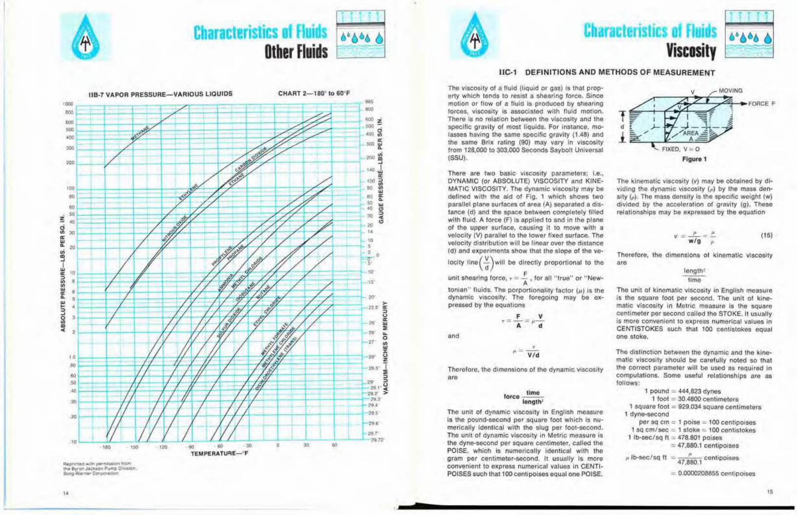
JIB-6 VAPOR PRESSURE-VARIOUS LIQUIDS
BOO
600500
400
.. II-f- I ]
-
I
:J-,..
rf t--
7I-
,
jJ T_o- - <--
-'- -2 3 4 5
TEMPERATURE-oK
Based on water having 1.00 specificgravity at 68° F., corresponding to aweight of 62.344 Ib.lcu. ft., and 1 psiequalling 2.310 feet.
o
400
1400
1600
Reprinted with permission fromthe Byron Jackson Pump Diyision,Borg-Warner Corporation
-30 o 30 60 90 120
TEMPERATURE-oF
'50 180 2'0 240
12
Reprinted with permission fromJ. F. Pritchard & Company.Kansas City. Missouri '3
Characteristics of FluidsOther Fluids
Characteristics of FluidsViscosity
IIC-1 DEFINITIONS AND METHODS OF MEASUREMENT
Therefore, the dimensions of kinematic viscosityare
(15)v ]セ]AAZwIg p
length'
time
The unit of kinematic viscosity in English measureis the square foot per second. The unit of kine-matic viscosity in Metric measure is the squarecentimeter per second called the STOKE. It usuallyis more convenient to express numerical values inCENTISTOKES such that 100 centistokes equalone stoke.
1 pound = 444,823 dynes1 foot = 30.4800 centimeters
1 square foot = 929.034 square centimeters1 dyne-second
per sq em = 1 poise = 100 centipoises1 sq em/sec = 1 stoke = 100 centistokes
1 Ib-sec/sq It = 478.801 poises= 47,880.1 centipoises
I' Ib-sec/sq It 47; centipoises, 80.1
= 0.0000208855 centipoises
The kinematic viscosity (v) may be obtained by di-viding the dynamic viscosity (1') by the mass den-sity (p). The mass density is the specific weight (w)divided by the acceleration of gravity (g). Theserelationships may be expressed by the equation
FIXED, V = 0
Figure 1
The distinction between the dynamic and the kine-matic viscosity should be carefully noted so thatthe correct parameter will be used as required incomputations. Some useful relationships are asfollows:
F VT = -=1'-
A d
There are two basic viscosity parameters; i.e.,DYNAMIC (or ABSOLUTE) VISCOSiTY and KINE-MATIC VISCOSITY. The dynamic viscosity may bedefined with the aid of Fig. 1 which shows twoparallel plane surfaces of area (A) separated a dis-tance (d) and the space between completely fiiledwith fiuid. A force (F) is applied to and in the planeof the upper surface, causing it to move with avelocity (V) parallel to the lower fixed surface. Thevelocity distribution will be linear over the distance(d) and experiments show that the slope of the ve-
locity line ( セI will be directly proportional to the
unit shearing force, T =.£: , for ail "true" or "New-A
tonian" fluids. The porportionality factor (I.L) is thedynamic viscosity. The foregoi ng may be ex-pressed by the equations
Therefore, the dimensions of the dynamic viscosityare
and
The viscosity of a fluid (liquid or gas) is that prop-erty which tends to resist a shearing force. Sincemotion or flow of a fluid is produced by shearingforces, viscosity is associated with fluid motion.There is no relation between the viscosity and thespecific gravity of most liquids. For instance, mo-lasses having the same specific gravity (1.48) andthe same Brix rating (90) may vary in viscosityfrom 128,000 to 303,000 Seconds Saybolt Universal(SSU).
force limelenglh'
The unit of dynamic viscosity in English measureis the pound-second per square foot which is nu-merically identical with the slug per foot-second.The unit of dynamic viscosity in Metric measure isIhe dyne-second per square centimeter, called IhePOISE, which is numerically identical with thegram per centimeler-second. II usually is moreconvenient to express numerical values in CENTI-POISES such that 100centipoises equal one POISE.
CHART 2-180°10 GO°FIIB-7 VAPOR PRESSURE-VARIOUS L1aUIDS
Reprinted with permission fromthe Byron Jackson Pump Division.Borg-Warner Corporation
100
80
6050
Z -40
14 15
7

Characteristics of FluidsViscosity
Characteristics of FluidsViscosity
The viscosities of most fluids vary appreciably withchanges in temperature. The influence of changein pressure usually is negligible.
The viscosities of fluids, such as mineral oil andwater, are unaffected by the magnitude and kindof motion to which they may be subjected as longas the temperature remains constant. Thus theratio of shear stress to shear rate is a constant forall shear rates, is independent of time, and zeroshear rate exists only at zero shear stress; such afluid is said to be Newtonian.
When the ratio of shear stress to shear rate in-creases as the shear rate increases, reversibly andindependent of time, a fluid is said to be dilatent.
When the shear stress to shear rate ratio is con-stant for shear rates above zero, is independent oftime, but when shear occurs only for shear stressabove a fixed minimum greater than zero, a fluidis said to be plastic.
When the ratio of shear stress to shear rate de-creases as shear rate increases, reversibly andindependent of time, and zero shear rate occursonly at zero shear stress, a fluid is said to bepseudo-plastic.
When the ratio of shear stress to shear rate de-creases as shear rate increases and is time depen-dent in that this ratio increases back to its "rest"value gradually with lapse of time at zero shearrate and stress, and decreases to a limit valuegradually with lapse of time at constant shear rate,
PERCENTAGE OF COMPONENT OILS
VISCOSITY BLENDING CHART
OIL A 0OIL B 100
«...o...«ena:w>Z::l
I-...o1Il>«enenCzouwen>I-(jjouen:>
150
400
2000
750
500
1000
200
t='1500 Z
WZoc.:;;ou>I-(jjouen:>:rCl:rw:rt:.
3000
70
50
55
300
60
45
100
90
80
40
100
o90
10
80
207030
60
40
50
50
40
60
3070
2080
IIC·2
1090
セ
I-- _. -
/./
セ./
セセ | Z N G A
A セ
M セ ,
1./
././
50
55
40
60
45
70
200
400
150
750
500
300
100
90
80
1000
2000
3000
t=' 1500ZwZoc.:;;ou>I-(jjoUen:>;:o...w:rt:.1Il...o...«ena:w>Z::l
I-...o1Il>«enenczouwen>l-t)oUen:>
a fluid is said to be thixotropic.
When the shear stress to shear ratio rate is con-stant for all shear rates at any given instant of time,but increases with time, a fluid is said to berheopectic.
Viscosity is measured by an instrument called aviscosimeter. A definite volume of fluid is allowedto flow through a capillary tube or orifice of speci-fied proportions and the time of efflux noted. In-struments of the capillary type, such as the Ost-wald, Bingham, and Ubbelohde viscosimeters areused primarily for fluids of low viscosity, such aswater. Instruments of the orifice type are usedcommercially for more viscous fluids such as pe-troleum products, and the time of efflux of thesample is taken as a measure of the viscosity. TheSaybolt viscosimeter is commonly used in theUnited States, the Saybolt Universal for fluids ofmedium viscosity and the Saybolt Furol for thoseof high viscosity. The viscosity is expressed inSeconds Saybolt Universal (SSU) or Seconds Say-bolt Furol (SSF). The relationship between SayboltUniversal viscosities and kinematic viscosities incentistokes is given in "ASTM Conversion Tablesfor Kinematic and Saybolt Universal Viscosities'"or by the ASTM Standard, Designation: 0446:Similar information for Saybolt Furol viscositiesmay be obtained from the ASTM Standard, Desig-nation: 0666.· The respective British counterpartsof the Saybolt Universal and Saybolt Furol viscosi-meters are the Redwood and Redwood Admiraltyviscosimeters. The Engler viscosimeter is used ex-tensively on the continent of Europe. Viscosimeterssuch as the Brookfield are particularly useful withnon-Newtonian fluids. There are many other vis-cosimeters for special pu rposes, discussion ofwhich is beyond the scope of this Manual. Viscosityconversion tables for use with the above described
viscosimeters are shown in Tables I1C-3 and 4. Aviscosity blending chart for use with oils is shownin IlC-2. Let oil (A) have the higher viscosity and oil(B) the lower viscosity. Mark the viscosity of (A) and(B) on the right and left hand scales, respectively,and draw a straight line connecting the marks asshown. The viscosity of any blend of (A) and (B) willbe shown by the intersection of the vertical linerepresenting the percentage composition and theline described above. See examples 1 and 2.
*American Society tor Testing Materials, 1916 Race St., Phila-delphia, Pa.
v = セ = -p.-p wIg
=0.000671970 ..!':-w
= 0.00107639 stokes
u sq em/sec
929.034
I), = centipoises
w = Ib/cu It
g = 980.665 em/sec/sec
= 32.1740 ft/sec/sec at sealevel and approximately 45degrees latit·ude
where
v sq It/sec
and
v sq ftl sec
16 17
7
Characteristics of FluidsViscosity
1 T1 TlCharacteristics of Fluids .t} /)66 ()
Viscosity 0 -v-u0 a <>
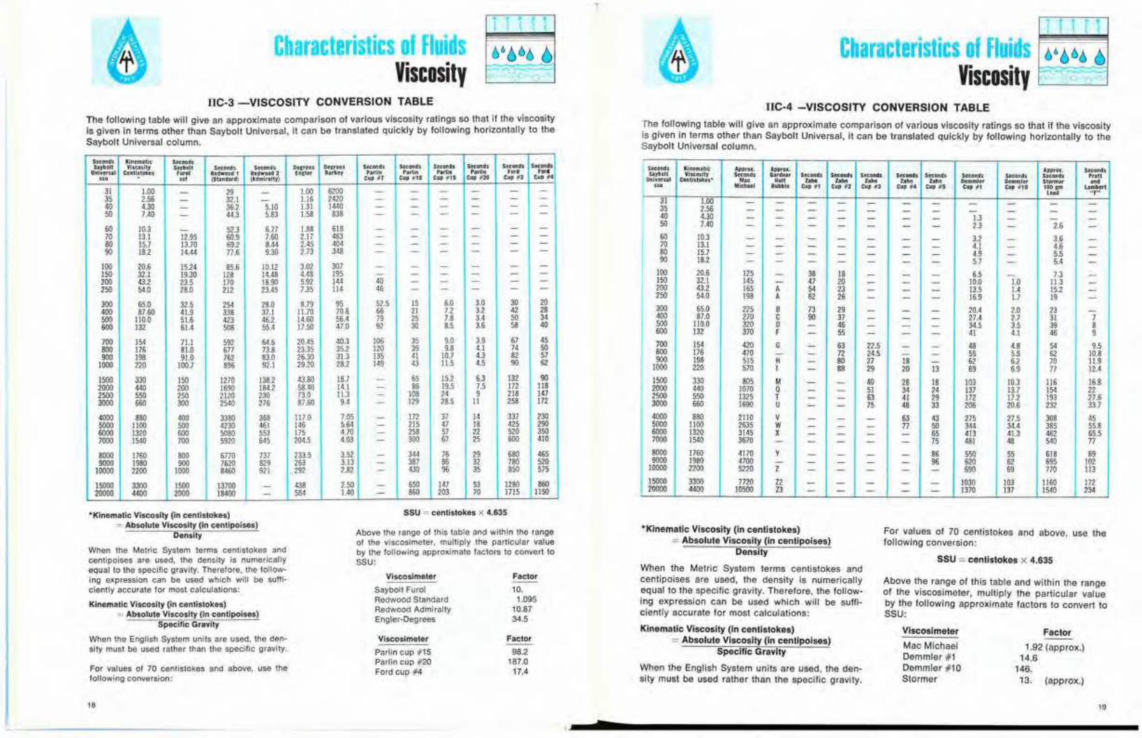
IIC-3 -VISCOSITY CONVERSION TABLE
The following table will give an approximate comparison of various カ ゥ セ 」 ッ ウ ゥ エ ケ ratings .so that if the viscosityis given in terms other than Saybolt Universal, it can be translated qUickly by followmg hOrizontally to theSaybolt Universal column.
I1C-4 -VISCOSITY CONVERSION TABLE
The following table will give an approximate comparison of various viscosity ratings so that if the viscosityis given in terms other than Saybolt Universal, it can be translated quickly by following horizontally to theSaybolt Universal column.
Seconds Kinematic SecondsDegrees Seconds Seconds Seconds Seconds Seconds SecondsSaybolt Viscosity Sayboft Seconds Seconds Degrees
Parlin Parlin Parlin Ford FordUniversal Centistokes Furol Redwood t Redwood 2 Engler Barbey ParlinCup #4'" .., (Standard) (Admiralty) Cup i7 Cup #10 Cup #15 Cup #20 Cup #3
31 1.00 - 29 - 1.00 6200 - - -35 2.56 32.1 1.16 2420 - - - - - -- -40 4.30 36.2 5.10 1.31 1440 - - - - - --50 7.40 44.3 5.83 1.58 838 - - - - - --
60 10.3 52.3 6.77 1.88 618 - - - - - --70 13.1 12.95 60.9 7.60 2.17 483 - - - - - -80 15.7 13.70 69.2 8.44 2.45 404 - - - - - -90 18.2 14.44 77.6 9.30 2.73 348 - - - - - -
100 20.6 15.24 85.6 10.12 3.02 307 - - - - - -150 32.1 19.30 128 14.48 4.48 195 - - - - - -200 43.2 23.5 170 18.90 5.92 144 40 - - - - -250 54.0 28.0 212 23.45 7.35 114 46 - - - - -
300 65.0 32.5 254 28.0 8.79 95 52.5 15 6.0 3.0 30 20400 87.60 41.9 338 37.1 11.70 70.8 66 21 7.2 3.2 42 28500 110.0 51.6 423 46.2 14.60 56.4 79 25 7.8 3.4 50 34
61.4 508 55.4 17.50 47.0 92 30 8.5 3.6 58 40600 132
700 154 71.1 592 64.6 20.45 40.3 106 35 9.0 3.9 67 4535.2 120 39 9.8 4.1 74 50800 176 81.0 677 73.8 23.35
4.3 82 57900 198 91.0 762 83.0 26.30 31.3 135 41 10.7149 43 11.5 4.5 90 621000 220 100.7 896 92.1 29.20 28.2
1500 330 150 1270 138.2 43.80 18.7 - 65 15.2 6.3 132 902000 440 200 1690 184.2 58.40 14.1 - 86 19.5 7.5 172 1182500 550 250 2120 230 73.0 11.3 - 108 24 9 218 1473000 660 300 2540 276 87.60 9.4 - 129 28.5 11 258 172
4000 880 400 3380 368 117.0 7.05 - 172 37 14 337 2305000 1100 500 4230 461 146 5.64 - 215 47 18 425 2906000 1320 600 5080 553 175 4.70 - 258 57 22 520 3507000 1540 700 5920 645 204.5 4.03 - 300 67 25 600 410
8000 1760 800 6770 737 233.5 3.52 - 344 76 29 680 4659000 1980 900 7620 829 263 3.13 - 387 86 32 780 520
10000 2200 1000 8460 921 ,292 2.82 - 430 96 35 850 575
15000 3300 1500 13700 - 438 2.50 - 650 147 53 1280 86020000 4400 2000 18400 584 1.40 - 860 203 70 1715 1150
Seconds Kinematic Approx. Approx. Approx. SecondsSaybort Viscosity Seconds Gardner Seconds Seconds Seconds Seconds Seconds Seconds Seconds Seconds PrattUniversal Centistokes* Moo Holt Zahn bh" Zahn Zahn Zahn Demmler Demmler Stormer ..d
'" Michael Bubble Cup #1 Cup #2 Cup #3 Cup #4 Cup #5 Cup #1 Cup #10 100 gm LambertLoad "F"
31 1.00 - - - - - - - -35 2.56 - - - - - - - - - - -40 4.30 - - - - - - - 1.3 - - -50 7.40 - - - - - - - 2.3 - 2.6 -
60 10.3 - - - - - - - 3.2 - 3.6 -70 13.1 - - - - - - - 4.1 - 4.6 -80 15.7 - - - - - - - 4.9 - 5.5 -90 18.2 - - - - - - - 5.7 - 6.4 -
100 20.6 125 - 38 18 - - - 6.5 - 7.3 -150 32.1 145 - 47 20 - - - 10.0 1.0 11.3 -200 43.2 165 A 54 23 - - - 13.5 1.4 15.2 -250 54.0 198 A 62 26 - - - 16.9 1.7 19 -300 65.0 225 B 73 29 - - - 20.4 2.0 23 -400 87.0 270 C 90 37 - - - 27.4 2.7 31 7500 110.0 320 0 - 46 - - - 34.5 3.5 39 8600 132 370 F - 55 - - - 41 4.1 46 9700 154 420 G - 63 22.5 - - 48 4.8 54 9.5800 176 470 - - 72 24.5 - - 55 5.5 62 10.8900 198 515 H - 80 27 18 - 62 6.2 70 11.9
1000 220 570 I - 88 29 20 13 69 6.9 77 12.41500 330 805 M - - 40 28 18 103 103 116 16.82000 440 1070 Q - - 51 34 24 137 13.7 154 222500 550 1325 T - - 63 41 29 172 17.2 193 27.63000 660 1690 U - - 75 48 33 206 20.6 232 33.74000 880 2110 V - - - 63 43 275 27.5 308 455000 1100 2635 W - - - 77 50 344 34.4 385 55.86000 1320 3145 X - - - - 65 413 41.3 462 65.57000 1540 3670 - - - - - 75 481 48 540 778000 1760 4170 Y - - - - 86 550 55 618 899000 1980 4700 - - - - - 96 620 62 695 102
10000 2200 5220 Z - - - - - 690 69 770 113
15000 3300 7720 Z2 - - - - - 1030 103 1160 17220000 4400 10500 Z3 - - - - - 1370 137 1540 234
SSU = centistokes X 4.635
Above the range of this table and within the rangeof the viscosimeter, multiply the particular valueby the following approximate factors to convert toSSU:
For values of 70 centistokes and above, use thefollowing conversion:
SSU = centistokes X 4.635
Above the range of this table and within the rangeof the viscosimeter, muitiply the particular valueby the following approximate factors to convert toSSU:
Factor
1.92 (approx.)14.6
146.13. (approx.)
Viscosimeter
Mac MichaeiDemmler #1Demmler #10Stormer
·Kinematic Viscosity (in centistokes)= Absolute Viscosity (in centipoises)
Density
When the Metric System terms centistokes andcentipoises are used, the density is numericallyequal to the specific gravity. Therefore, the follow-ing expression can be used which will be suffi-ciently accurate for most calculations:
Kinematic Viscosity (in centistokes)= Absolute Viscosity (in centipoises)
Specific Gravity
When the English System units are used, the den-sity must be used rather than the specific gravity.
Factor
10.1.095
10.8734.5
98.2187.0
17.4
FactorViscosimeter
Parlin cup #15Parlin cup #20Ford cup #4
Viscosimeter
Saybolt FurolRedwood StandardRedwood AdmiraltyEngler-Degrees
For values of 70 centistokes and above, use thefollowing conversion:
*Kinematic Viscosity (in centistokes):::: Absolute Viscosity (in centipoises)
Density
When the Metric System terms centistokes andcentipoises are· used, the density is numericallyequal to the specific gravity. Therefore, the follow-ing expression can be used which will be suffi-ciently accurate for most calculations:
Kinematic Viscosity (in centistokes)= Absolute Viscosity (in centipoises)
Specific Gravity
When the English System units are used, the den-sity must be used rather than the specific gravity.
18 19
p
Sectionm
z
Fluid Flow

Fluid FlowGeneral
IIIA-1 -FLUID FLOW-GENERAL
TrON 1 PIPE
The resistance to the incompressible flow of anyfluid in any pipe may be computed from the equa-tion
wherein
h, = Frictional resistance in feet of fluidL = Length of pipe in feetD = Average internal diameter of pipe in feetV = Average velocity in pipe in feel/secondg = Acceleration due to gravity in feet/second/
second. Hereafter, the value 32.17 feel/second/second for sea level and 45 de-grees latitude will be used.
I = Friction factor
Equation (2) was combined with Equation (1)and solutions carried out for each kind and size ofpipe. These were used to construct large-scalelogarithmic plots from which the values of (h,)shown in Section IlIB, Tables 1-31 incL, wereobtained.
TABLE A
-5to+l0-5to + 5oto +10
Probablemaximum
variation in IPer Cent£, feet
0.000150.00040.0005
Material
Steel or wrought ironAsphalt-dipped cast ironGalvanized iron
(1 )L V'
h/=1 --D 2g
SECTION 2- CONSTRUCTION OFCHARTS AND TABLES
wherein
V = Average velocity in feel/secondD = Average internal diameter in feetv = Kinematic viscosity of the fluid in square
feet/second
The Colebrook Equation 1"12
_1_ = -2 10 (_'_ + 2.51) (2)vI g" 3.7D RVt
offers a reliable means for computing the frictionfactor (I) to be used in Equation (1).
The Reynolds Number (R) is given by the equation
R= VDv
(3)
SECTION 3· OLD PIPES
A study of References 8, 9, 10, 11 in Section VIshowed that the problem of estimating the frictionfactors for old pipes or allowing for the deteriora-tion of new pipes is beyond the scope of this Hand-book.The deterioration of pipes with age depends on theparticular chemical properties of the fluid and themetal with which it is in contact. It is recommendedthat prior experience be considered and local watersupply officials be consulted where it is necessaryto estimate the friction losses in old pipes or toallow for the aging of new pipes. References 8, 9,10, 11 of Section VI may be consulted for generalinformation on the subject. For commercial instal-lations, it is recommended that 15 percent beadded to the values shown in Tables 1-31.
References 1, 2, 3, 4, 5, 6 and 7 in Section VI werestudied to obtain the best value of the roughnessparameter (0) and the probable variations in thefriction factors for new pipes. The probable varia-tions in (t) for some classes of new clean pipe aregiven in Table A.
SECTION 4-TABLES OF FRICTIONLOSS FOR WATER EXPLANATION
. Frictional resistances for water flowing in new,clean steel pipe (Schedule 40)' or in asphalt-dipped cast iron pipe are given in Section IlIB,Tables 1-31 incL, herein."
The tables show the discharge in cubic feet persecond, the average velocity in feet per second,and the velocity head in feet for any fluid in a cir-
23
7

Characteristics of FluidsGeneral
Fluid FlowGeneral
SECTION 5-VALVES AND FITTINGS
The resistance to flow caused by a valve or fittingmay be computed from the equation
wherein
h = Frictional resistance in feet of fluidV = Average velocity in feet/second in a pipe
of corresponding diameterg = 32.17 feet/second/secondk = Resistance coefficient for valve or fitting
SECTION 6-FRICTION FACTORDIAGRAMS
As previously stated, the resistance to the in-compressible flow of any fluid in any pipe may becomputed from the equation (1)
L V'hl = 1--° 29
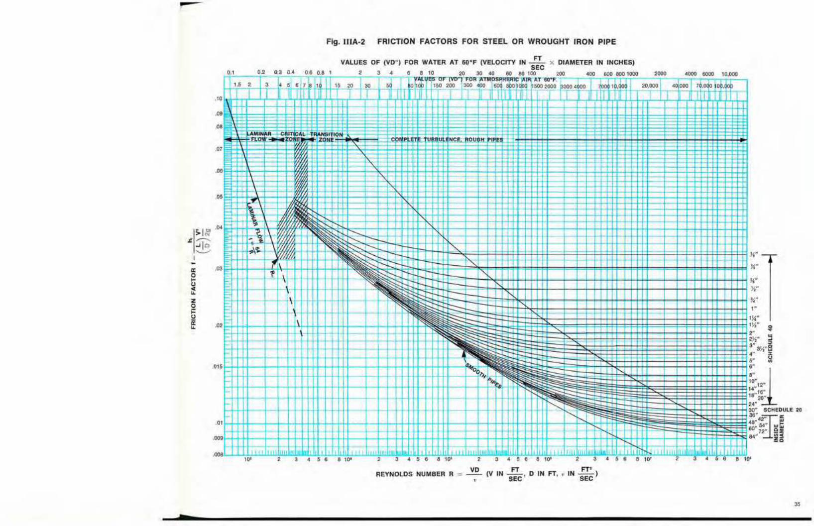
Values of (I) may be obtained directly from Fig.II1A-1 where the pipe is new clean asphalt-dippedcast iron, from Fig. ll1A-2 where the pipe is newclean steel of Schedule 40 wall thickness, or fromFig. IllA-3 which applies to any size and type ofsurface. The probable variations in (I) for someclasses of new clean pipe are given in Table A. Itwill be necessary to know the approximate value of
the relative roughness factor, .2- to enter Fig. IIIA-3D
and this can be obtained, for several kinds ofpipes, from Fig. lIIA-4.
If the fluid is fresh water at 60' F or atmosphericair at 60' F the scales at the top of Figs. II1A-1-3incl., may be used. For convenience in air andwater computations only, the scale readi ng is theproduct of the average velocity in feet/second andthe internal diameter in inches, (VD'·).
For other fluids or temperatures the scales at thebottom of Figs. IIIA-1-3 incl., must be used. Thescale reading is the Reynolds Number, R, givenby equation (3).
The data for Figs. lIlA-1-3 incl., were obtained di-rectly from solutions of Equation (2). Figs. t1lA-4and IlIA-5 were taken from Reference 2 with minorchanges.
Values of the kinematic viscosity (u) at varioustemperatures are given in Fig. IIlA-5 for a numberof different fluids. The Reynolds Number also maybe obtained directly from Fig.IIlA-5with the aid ofthe quantity (VD") mentioned above. The tracerline shows that for kerosene at 175 0 F flowing withan average velocity of 12.5 ft/sec in a pipe of 4inches internal diameter, the Reynolds Numberwould be 3.5 x 10', In cases where viscosities areobtained from sources other than Fig. llIA-5, it isabsolutely essential that they be expressed in sqIt/sec in order that they may be used with Fig.IIIA-5 or Equation (3). Kinematic viscosities mea-sured in stokes or centistokes may be convertedto (v) in square feet/second by the formula.
(6)( B) ""k = 3.50 Ian 2wherein
B= total conical angle of the increaser indegrees
Equation (6) applies only to values of ebetween 7.5and 35 degrees. Noteworthy is the fact that above50 degrees a sudden enlargement will be as goodor better than a conical increaser. Values of (k) forconical diffusers as reported by Reference 11 ofSection VI are shown in Section IllB, Fig. IlIB-6.The values shown include the entrance mouthpiecewhich accounts in part for the increase over Gib-son's values for conical increasers. Resistancecoefficients for reducers, as reported by Russell aregiven in Section IllB, Fig. lIIB-7.
wherein
h = Frictional resistance in feet of fluidV, = Average velocity in feet/second in the
smaller (upstream) pipeA, = Internal cross-sectional area of the smaller
pipe in square feetD, = Internal diameter of the smaller pipe in feet
Vo}A2 = Corresponding values for the largerD, (downstream) pipeg = 32.17 feet/second/secondk = Resistance coefficient, usually taken as
unity since the variation is almost alwaysless than ±3 per cent.
Equation (5) is useful for computing the resistanceto flow caused by conical increasers and diffusers.Values of (k) for conical increasers based on datareported by Gibson,g, 21 are given in Section IlIB,Fig. IllB-6 or may be computed by the equation
The resistance to flow caused by a sudden en-largement may be computed from the equation
h = k IV, - V,l'29
( A')'V"=k 1-_ -A, 29
= k[1 - HセZI 'J [セ
- [(_0,)' J' V,'- k - 1 2 (5)0, 9
'Note 1: ANSI 836.10 of the American National Standards Insti-tute.
セ G t ィ ・ Tables should not be applied to problems involving thepumping of fluid-solid mixtures. It is suggested that priorexperience be considered and that qualified sources beconsulted where it is necessary to estimate the frictionlosses in pipes carrying solids in suspension.
For paper stock suspensions, see Section IllB.···For easy references, values of GPM and hI are shown in
shaded column.
Cast iron flanged elbows and drainage-type elbowsmay be expected to approximate pipe bends. Valuesof the resistance coefficient (k) may be taken fromSection llIB. The solid line curves in Fig. IlIB-5aare given by Reference 12a of Section VI with therange of scatter of the test points as indicated.The broken line curves may be used as a guide toprobable resistance coefficients for intermediate
values of the relative roughness ヲ 。 」 エ ッ イ L セ N A valueD
of, = 0.00085 feet will be satisfactory for uncoatedcast iron and cast steel elbows. Resistance coeffi-cients for pipe bends with less than 90 degree de-flection angles as reported by Wasielewski'" 18 areshown in Fig.IIlB-5b. The curves shown are forsmooth surfaces but may be used as a guide toapproximating the resistance coefficients for sur-faces of moderate roughness such as clean steeland cast iron. Figs. llIB-5a and IlIB-5b in Section
lllB are not reliable below セ = 1, where R is theD
radius of the elbow in feel. The approximate radiusof a flanged elbow may be obtained by subtractingthe flange thickness from the center-to-face dimen-sion. The center-to-face dimension for a reducingelbow is usually identical with that of an elbow ofthe same straight size as the larger end.
The resistance coefficients for miter bends as re-ported by Shubert'" 17b are shown in Section lIlB,Table 33. The rough pipe used in the Shubert in-
vestigation had a relative roughness factor, -'-D
of about 0.0022. Reference 12b of Section VIshould be consulted for information on the varia-tion of the resistance coefficients with variation inthe Reynolds Number.
(4)ィ]ォセ29
Values of (k) for valves and fittings may be foundin Section IlIB. Reference to the literature will re-veal wide differences in the published values of(k) for all types of valves and fittings. The availabledata are inconclusive. As indicated in Section III(B),flanged valves and fittings usually exhibit lower re-sistance coefficients than screwed valves and fit-tings. The resistance coefficients decrease with theincreasing size of most valves and fittings.
cular pipe of the same diameter as that specifiedin each table for rates of flow in gallons per min-ute. The values of the friction head (hi) in feet offluid per 100 feet of pipe apply to any fluid havinga kinematic viscosity, u = 0.00001216 square feetper second (1.130 centistokes) which is the valuefor pure fresh water at 60' F... ' The friction heads
are average values for pipes having the.!.- valuesD
given in the tables, where (,) is a linear measureof the absolute roughness of the pipe walls and(D) is the internal diameter of the pipe. Further in-formation on the roughness parameter is given inSection IV.
The tabulated values of (hi) are in feet of purefresh water (60' F) per 100 feet of new clean steelpipe (Schedule 40)' or of new clean asphalt-dippedcast iron pipe as specified.
No allowance has been made for age, differ-ences in diameter resulting from manufacturingtolerances, or any abnormal conditions of interiorsurface. Any factor of safety must be estimatedfrom the local conditions and the requirements ofeach particular installation. An example illustratingthe use of the tables will be found in Section J1IB.
24 25
tr

Fluid Flow6eneral
Fluid Flow6eneral
"9.56 x 0.1723
0.000023
= 71,600
If the Reynolds Number is above 4000, the flow willusually be turbulent and the curves in Figs. IlIA 1-3 incl., apply. The range R セ 2000-4000 is calledthe critical zone in which the flow may be highlyunstable and the friction factor indeterminate.
--=- = 0.000180D
k '" 0.10
V = 3.230 = 5.90 ft/sec'0.5476
and
so that
The velocity,
V' (590)'The velocity head, - = -'- = 0.541 feet
2g 64.34
The kinematic viscosity, from Fig. IIIA-5, will bev = 0.0000026 square feet/second
The Reynolds Number, by Equation (3), will be
R = VD = 5.90 x 0.8350 = 1890000 = 1.89 X 106" 0.0000026 "
セtィ・ウ・ also may be obtained from Section 11IB, Table 17, byinterpolation.
tained from Section IVA.
Diameter, D = 10.020 inches = 0.8350 feet
Area, A = 0.5476 square feet
Relative roughness factor, --=- = 0.000180D
. 1450The discharge, Q = = 3.230 cu ft/sec'
7.481 x 60
The resistance coefficients for the fittings may beobtained from Section IIIB, Tables 32(a), 32(b)and 32(c). as follows:
Entrance, k = 0.5 (assuming a square-edged inlet)
Wedge-disc gate valve, k = 0.06
From Section IllS, Fig. IIIS-5a
For 90 degree pipe bend,
R 50D 10.020
"'5
The friction factor may be taken from Fig. IIIA-2,f = 0.0139. The head loss due to pipe friction, byEquation (1), will be
L V'h,=1 --
D 2g
= 0.0139 HセI 0.5410.8350
= 2.07 feet
P _ (239 + 1) 62.34 x 0.8090- 144
'" 84 psi
Example 2. Use 01 Friction Factor Diagrams. Asimplified boiler feed pump installation is shown inFig. IIlA-7. The rate of flow is 1450 gpm at thepump. It is requi red to compute the net positivesuction head (h".), the total suction head (h,). thetotal discharge head (h,) and the total head (H).
The pressure head at the center of the gauge willbe 1 foot greater than this value because the gaugeis 1 foot below the center of the pipe. Therefore,the reading of the discharge pressure gauge willbe
The pressure head at the centerline of the pipewhere the gauge is connected to the dischargepipe will be the pressure head in the dischargetank plus the head loss in the pipe and fittingsminus the velocity head at the point where thegauge is connected. No difference in elevations isinvolved because the pipe is horizontal. Therefore,
Required pressure head= 142.8 + 90.3 + 7.63 - 1.42
'" 239 feet Of kerosene
h=k セ2g
= [2.2 + 0.17 + 2 (1.0) + 1.0] 1.42= 7.63 feet of kerosene
The specific gravity of kerosene at 70° F relativeto water at 60° F may be estimated from SectionlIC, to be 0.809. The specific weight of water at
60° F is 62.34 Ib/cu. ft. from Section IIA. There-fore, the pressure head at discharge into the pres-sure tank will be
h" = (62.00 - 62.52) + 90.3 + 7.63 + 142.8'" 240 feet of kerosene
50 x 144Tank pressure head = -=-'..:...-'--'--'---
0.809 x 62.34
'" 142.8 feet of kerosene
The discharge head (ho) will be
SOLUTION: a. Suction Line. The following proper-ties of 1O-inch Schedule 40 steel pipe may be ob-
The resistance coefficients for the fittings, fromSection IIIB, Tables 32(a), 32(b) and 32(c), will be
Square-edged inlet, k = 0.5Wedge-disc gate valve, k = 0.17
The head loss in the fittings, by Equation (4) will be
The resistance coefficients for the fittings, fromSection IIIB, Tables 32(a), 32(b) and 32(c), will be
Swing check vaive, k = 2.2Wedge-disc gate valve, k = 0.17Regular screwed elbow, k = 1.0Sudden enlargement, k = 1.0
Therefore, the pump actually operates with a suc-tion lift of 1.50 feet of kerosene.
The suction head (h,) will be
h, = (67.00 - 62.52) - 5.03 - 0.95
= 4.48 - 5.98
= -1.50 feet of kerosene
V'h=k-
2g
= (0.5 + 0.17) 1.42
= 0.95 feet of kerosene
b. Discharge Line. The head loss due to pipefriction, by Equation (1), will be
L V'h,=1 --
D 2g
= 0.0226 ( 485 ) 1.420.1723
= 90.3 feet of kerosene
The head loss in the fittings, by Equation (4), will be
turbulent. The friction factor, from Fig. IllA-2, willbe 1 = 0.0226. The head loss due to pipe friction,by Equation (1). will be
L V'h,=1 --
D 2g
= 0.0226 (0. セ [ R S I 1.42
= 5.03 feet of kerosene
(7)
(8)
v = 0.00107639 x stokes
= 0.0000107639 x centistokes
For further information on viscosity, see SectionlIC.
If the Reynolds Number is less than 2000, theflow is laminar and the friction factor for any fluidin any pipe is given by the equation
1= セR
Example 1. Use 01 Friction Factor Diagrams. Apump delivers kerosene at 70° F through 512 feet ofnew 2-inch steel pipe (Schedule 40) and screwedfittings to a tank (See Fig. IIIA-6). The tank pressureis maintained constant at 50 psi at the level of thedischarge pipe. It is required to estimate the suc-tion head (h,), the discharge head (h,,), and thereading of the discharge pressure gauge (Po) whenthe rate of flow is 100 gpm.
SOLUTION: a. Suction Line. Table 9, SectionIIIB, shows the average velocity (V) to be 9.56
V'ft/sec and the velocity head, _ to be 1.42 feet of2g
kerosene. Fig. IIIA-5 shows the specific gravity ofkerosene to be 0.813 at 60/60 and the kinematicviscosity (,,) to be 0.000023 sq ft/sec at 70° F. Sec-tion IVA, shows the internal diameter of the pipeto be 0.1723 ft. The Reynolds Number, by Equation(3), will be
As an alternate procedure, determine the quantity(VD") and use Fig. llIA-5 at 70° F. Proceed from theintersection of the curve labelled kerosene and 70°F to the (VD") value of 19.8. The resulting Reynoldsnumber is aproximately 7 x 10⁴•
This is above the critical zone and the flow will be
26 27
t

Fluid FlowGeneral
Fluid FlowGeneral
10.19 x 0.63540.0000026
The total suction head is given by
hs = hs"I" + hVPll - ha
h, = 144 p,w
144 x 14.7
58.82= 36.0 feet
Wherein w =58.82 Ib/cu ft at T = 250 0 F from Sec-tion IIA. Therefore, the total suction head is
h, = 62.17 + 73.5 セ 36.0= 99.67'" 100 feet of water at 250 0 F.
(9)[1 2 JV,'
h= (c:-) -1 2Q
k = 0.266
h = Head loss in feet of fluidC" = Coefficient of velocity for nozzleV, = Velocity at throat (smallest cross-section)
of nozzie in feet/secondg = 32.17 feet/second/second
wherein
V,'2g
Yl... (E.'.)' v.l..2g = D2 2g
= (7.625)4 1.613.750
= 27.5 feet
h = [(o.:S -1J27.5
= (1.041 - 1) 27.5
= 1.13 feet
The coefficient of velocity has the same numericalvalue as the coefficient of discharge for mostsmooth nozzles such as are used in Venturi Meters.The throat velocity head may be obtained fromthe pipe velocity head,
Therefore, by Equation (5)
h = (V, - V2l' = (17.85 - 10.19)' = 0.91 feet2g 64.34
The total loss due to the elbow will be
h = 0.45 + 0.91 = 1.36 feet
The head loss in the Venturi Meter will be partlyin the meter nozzle and partly in the diffuser. Thenozzle loss may be computed by the formula
by
Therefore, the nozzle loss will be
The loss in the 16-inch long diffuser may be esti-mated by Equation (6) or, from Section 1I1B, Fig.IIlB-6 as follows:
D, - D, = 7.625 - 3.750 = 3.875 =0.1212L 2 x 16 32
for which
The friction factor, from Fig. IIIA-2 will be f =0.0145.
The head loss due to pipe friction, by Equation (1),will be
As before,
--=-- = 0.0102 =0.00152D 6.69
and from Section IIIB, Fig. 1I1B-5a:
k '" 0.28
V'h =k- =0.28 x 1.61 =0.45 feet
2g
L V'h,=f--D 2g
= 0.0145 H セ I 1.610.6354
= 3.97 feet
The head loss in the 6-inch by 8-inch dischargeelbow may be estimated from Section IVA Tablesfor 6-inch Schedule 80 pipe, as follows:
D = 5.761 inchesA = 0.1810 square feet
Average diameter of elbow
5.761 + 7.625= ====-
2
= 6.69 inches
R 11.75Average- = --
D 6.69
= 1.76
V, = 10.19 ft/sec
= 2,490,000
= 2.49 x 10"
The loss caused by changing the direction of thefiow will be
An additional loss will be caused by the use of theelbow as an increaser. This may be estimated as asudden eniargement loss as it is unlikely that theelbow will act as favorably as a straight increaser.
The inlet velocity V, =.9..= 3.230 = 17.85 ft/sec, A 0.1810
As before,
= 144 P"l'o/w144 x 30
=58.82
= 73.5 feet
hVP:l
and
b. Discharge Line (250· F). The following prop-erties of 8-inch Schedule 80 steel pipe may be ob-tained from Section I VA.
Diameter, D =7.625 inches =0.6354 feet
Area, A = 0.3171 square feet
Relative roughness, -' = 0.000236D
The velocity, V =.9.. = 3.230 = 10.19 ft/secA 0.3171
V2 (1019)'The velocity head, - = . = 1.61 feet
2g 64.34
The Reynolds Number,
R= VDv
wherein
h, = total suction head in feet (positive)h" = net positive suction head in feeth"I" = vapor pressure of liquid in feet absoluteh, = atmospheric pressure in feet absolute
Assuming the atmospheric pressure to be 14.7psia, and remembering that the vapor pressure ofthe water in the direct contact heater is 30 psia,
,0.0102 1Average - = = 0.001
D 9
The total resistance coefficient for the fittings inthe suction Iine will be
Total k = 0.5 + 2 (0.06) + 4 (0.10) + 0.38 = 1.40
The head loss due to the fittings, by Equation (4),will be
and
ィ ] ォ セ2g
= 1.40 x 0.541= 0.76 feet
The roughness parameter for cast fittings may betaken as,
,= 0.00085 x 12 = 0.0102 inches
For reducing elbow,
Average £!. = 9.5 = 1.06D 9
The total head loss in the suction line
= 2.07 + 0.76 = 2.83 feet.
The net positive suction head, (h".), is the totalsuction head in feet of liquid absolute determinedat the suction nozzle and referred to datum lessthe vapor pressure of the liquid in feet absolute.The datum is the centerline of the pump for hori-zontal pumps. The pressure in the direct contactheater is 30 psi absolute which is equal to thevapor pressure of water at 250 0 F. Therefore, theheater may be considered to be at atmosphericpressure for the purpose of computing the netpositive suction head. The net positive suctionhead will be
h" = (132.00 セ 67.00) - 2.83=65.00 - 2.83 = 62.17'" 62 feet of water at 250 0 F
k '" 0.38 for a straight size elbow
The effect of the reduction of area in a reducing el-bow is difficult to estimate. It usually reduces theloss below that to be expected in an equivalentstraight size elbow. No further allowance will bemade here because the elbow loss is aiready small.
Therefore,
28 29
t
Fluid FlowGeneral
Fluid FlowGeneral
The friction factor, from Fig. lIIA-3, will be
From Section lIIB, Tables 32(a), 32(b) and 32(c).
at T = 250 0 F, w =58.82 Ib/cu ft
The resistance coefficients for the fittings may beobtained;
The total head for the pump will be
H = hd - h,
= 2508 - 100
"" 2408 feet of water at 250 0 F
Economizer pressure head friction loss
900 x 14458.82
= 2203 feet of water at 250 0 F
The total discharge head will be
hd = 57.25 + 2203 + 16.21 + 11.44 + 220
= 2507.90
"" 2508 feet of water at 250 0 F
It should be noted that the pipe friction and filtinglosses in the discharge line are a very small por-tion of the total discharge head. Therefore, the de-gree of refinement of the preceding computationsis unwarranted for an installation of this type. Theindicated procedure may be useful in the solutionof other problems where the hydraulic losses aremore important.
55.59Friction loss =12.11
58.82
= 11.44 feet of water at 250 0 F
The head loss in the fittings, by Equation (4), willbe
h = [0.5 + 4 (0.075) + 6 (0.10) + 2 (0.29) + 1.0] 1.81= 5.39 feet
and
The total head loss due to friction in the 350 0 F dis-charge line wili be
h = 6.72 + 5.39
= 12.11 feet of water at 350 0 F
exclusive of the loss in the pressure regulator.
All head losses should be expressed in feet ofwater at the pump temperature (250 0 F) beforecomputing the pump discharge head. The neces-sary conversions, based on the specific weights,are as follows;
Discharge line, 350 0 F,
For 90 degree flanged elbow,
k = 0.29, the same as for the 250 0 F discharge line.
for which
The expansion loop may be considered as three90 degree pipe bends, making a total of six pipebends in the line.
..0.. = 0.000236D
k = 0.10V = .9.= 3.418 = 10.78 ft/sec
A 0.3171The velocity,
The head loss due to pipe friction, by Equation (1),will be
f =0.0143 for -' =0.000236D
at T =350 0 F, w =55.59 Ib/cu ft
58.82The discharge, Q =3.230 -- =3.418 cu ft/sec
55.59
L V' 165hI = f - -- = 0.0143 1.81 = 6.72 feet
D 2g 0.6354
V' (1078)'The velocity head, - = . =1.81 feet2g 64.34
The kinematic viscosity, by Fig. IIlA-5, will be
v = 0.0000019 sq ft/sec
The Reynolds Number,
R = VD = 10.78 x 0.6354 = 3 600,000 = 3.6 x 10"u 0.0000019 '
Entrance from heater,
k = 0.5 (assuming a square edged inlet)
The head loss in the Venturi Meter will be
h = 1.13 + 4.21 = 5.34 feet
From Section IIIB, Tables 32(a), 32(b) and 32(c)
Swing check valve, k = 2.0Wedge-disc gate valve, k = 0.075Sudden enlargement at heater, k = 1.0
Resistance coefficients for the remainder of thefittings may be obtained;
From Section IIlB, Fig. IIIB-5a; 90 degree flangedelbow,
and
for which
R 11.75
D 7.625
= 1.54
!.- = 0.0102 = 0.00134D 7.625
and
h= k{Hセj - Qイセセ= 0.266 [( 7.625) 2 _ 1] 2 1.61
3.750
= 4.21 feet
.h = [2.0 + 2(0.075) + 0.29 + 1.0] 1.61= 3.44 x 1.61 = 5.54 feet
k "" 0.29
The head loss in these fittings, by Equation (4) willbe
The total friction head loss in the 250 0 F dischargeline will be
h = 3.97 + 1.36 + 5.34 + 5.54
Wedge-disc gate valve,
k = 0.075
Heater and pressure regulator,
F" I (40+50)144nctlon ass = 58.82
= 16.21 feet of water at 250 0 FSudden enlargement to economizer,
k = 1.0= 220 feet of water at 250 0 F
Static Head friction loss
c. Discharge Line (350· Fl. The volumetric rateof flow will be increased due to the expansion ofwater in the heater. The specific weight at eachtemperature, from Section !lA, will be;
From Section lII(B), Fig. IIlB-5a; 90 degree pipebend,
R 40D 7.625
= 5.25
= (127.00 - 77.00) 55.59 + (77.00 - 67.00)58.82
= 47.25 + 10.00
= 57.25 feet of water at 250 0 F
30 31
¢
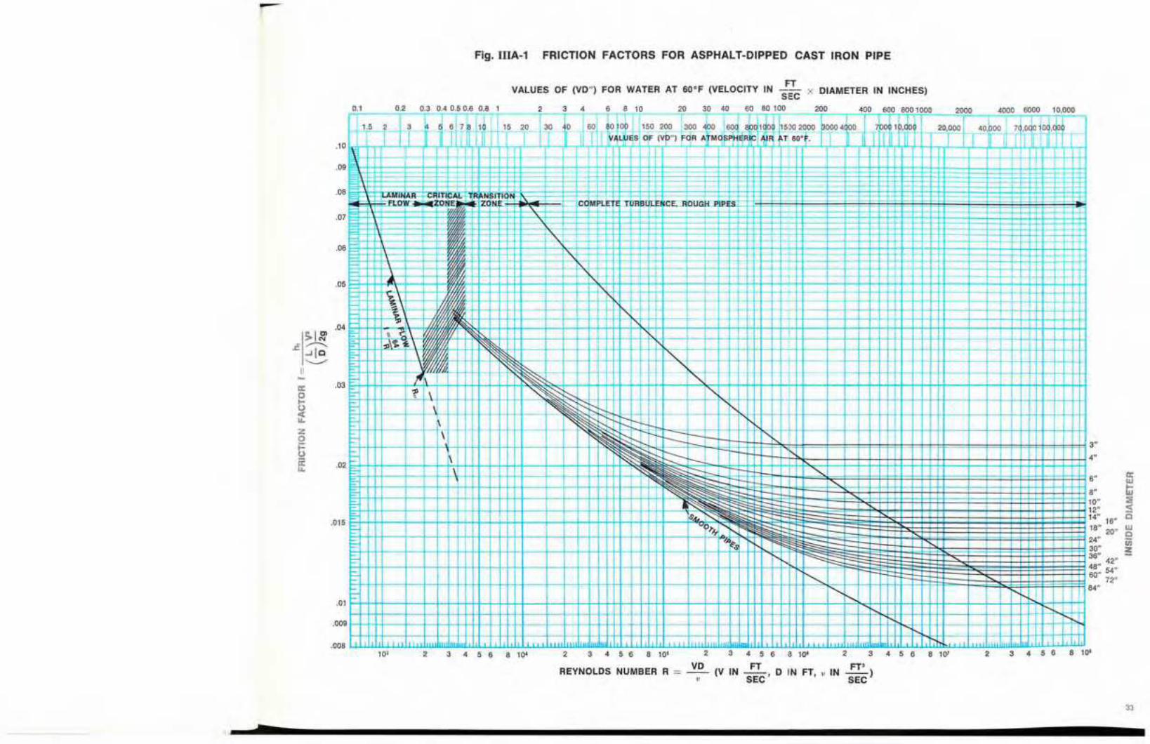
Fig.IIIA-1 FRICTION FACTORS FOR ASPHALT-DIPPED CAST IRON PIPE
-
--
--1---1--+-+
-f-1--
VALUES OF (VD") FOR WATER AT GO°F (VELOCITY IN ::c x DIAMETER IN INCHES)
2 3 4 6 810 20 30 40 60 80 100 ⦅MMMM]RZZイッッZZMMMイMMMNZT」ケッZZoッtVLッセoイXLPZ[oョャPイZPセPMセRセPセPPセ⦅L⦅NNNZTセPセPPセVセP[ZZPP[NNNNLNNZQN[ZNPZ[ZZPPセPZNNNNNNL
20 30 0 Q' セoセo I 150 200 300 '\00 Vセ 100 UPPRセP⦅ 0,q04doo poAQNー[ェNjNZZZoh⦅NNNLNNNNZRBBPGMGZZLPセPLPQ 40,boo 7J,oJoio L、ッセI I y-", セウ OF (VO") fqR a セ m ア ー p セ EjR C T 60oF. I III II T I I II II T"t t-<
J +-t+t-
03 0405060810201
l-+-,lr,S,------,2r--+3 _ .1rr QセセU,101.:!.+rr'-Y--,L.,hLJi-4'.WIJ..f-+-Irnr'-.....,-+-,
I
,08
,07CDM LEU t RBUE CE;::FOUCH:I I! S
,06
I-- -1-+-+-1--1- KセiMMMKKMKMKMKKKMエMhMKKエKヲMMMMMOMMエMMエMhMMhKKMKMiMKMャ
3"
4"
6"
84"
II:W
8" t:i10" :;;12" oct14" 16" Q
: 18" 20" セ
24" Cij30" l!:36" 42"
I 48" 54"I 60" 72"
I I I
, ,1 I
f---+-f--H++++-t-++1+_·I-+++I+++++-+-H
I"
4+-1-++11+--1-+-+-f-t--H-J',,+-f-t-++---1--+- - -+--1-1-1-1-+
セl=-I-
セ セ セ セ,01 fセKエKKMMセKKKエKKKKKQKャMMセKKKhMKKKKQKャMMiMKKMhhMKKKKMャKMゥiMMKMMエNN]ZBエNNNhhMエKKKKKiMMKMKMMiMhMphZZZKMエゥMエQ I'
,04E- \I .-1\ セ
: ャMNャセMKN|⦅ wエhKhtiKセ 「、KKMMMャMェNMKMKKKKKMhMKKセLLM」MiMェNMKMKKKKKMhMKMヲMMMMKMKMMQhMKKKKKKKMhMMMKMKMQMhMヲKKKKMhQ
EF-++++--+-H
·WI"f/J.1. pGNャサhMhKMiMKMnゥセセセG rt--lH-+-+-+-t+--l エ M K K K M M B セ K K h K K K M h M K K K M K M i K M K M K M K K K K M i h M K K i M M M K M M M i i M M i M K K K M i M M i M M i M K K K セE- It セ "-,03 E;:.++++--I-,?J..':'Mヲ|G|MKMKKKKMiMKKKKヲGセセセセセセMKKMiMKKKMャMKiMhMKセゥBZKMhMエKQMKKKエKMエMhhMKKKKMKエKエMイMMKMエMKMMエMQhMエKMエKエエQ
\ セ t-- r-- i'.セ ᄃ G ヲ エ [ セ M A Z イ Z Z Z K h M h M M K M K M h M n K K K K K h M M K M K M h M K Q i M h K K K K K M M K M K M K M Q K j N K ェ ヲ M K K K K i
I- \ ,,++++-++-H-f--+ セ セ t:-l I セ "'r-.
セB イセ セセ\ ,-
I=F-++++--+-+-+-J-V-f-HK h K K M M エ M M エ M K K M K M K K セ i M ヲ セ
セ セ セセ セ L セ.015 E-l+++-+--1--1H++++-I-++-if+-+-+--1-+++++-H+H---P"ol:2+<セ セ セ
II:oo<Ii.
Zoi=oirIi.
-セ I '">'"M セ
J: .... Ie"---/
II
REYNOLDS NUMBER R =
LPPYQMMェKKKMMャMMiMiセMKNjMiNKMwMKMiMiMMMャMセMihKNjMiNKMiMKMKMiMiMMKセセMKKKKKMiMKKャKMKMKMKMKKr^ォQMKKQKMKMKMKMKKヲKhMヲヲBh ...,008 エᄆLエエェャセ Bセ Bセ ,,,±;:;,,,,jj;jj;ttJljLᄆエエェャセ Bセ LLLェセLLLェ[[[ェエ[ャ[エエャᄆエエエ[エェエLセ Bセ LLLᄆセLLェエ[ェ[ェ[ェェエエャNᄆエエェェセLセ LLLᄆLLセ[[[ェエ[ェェェ[ェセャエェ NZェセエNLセNセ NBセiエ ᄋェBエ[[[エ[エ[ェ[エエエセセセ
10' 2 3 4 5 6 8 10' 2 3 4 5 8 8 10' 2 3 4 5 6 8 10' 2 3 4 5 6 8 10' 2 3 4 5 6 8 10'
vセ (V IN :ETC' D IN FT," IN Z[セI
33
7
-Fig. IIIA-2 FRICTION FACTORS FOR STEEL OR WROUGHT IRON PIPE
VALUES OF (VD") FOR WATER AT GO°F (VELOCITY IN セ x DIAMETER IN INCHES)SEC
01 02 03 04 06 08 1 2 3 4 6 8 10 20 30 40 60 60100 200 400 6008001000 2000 4000 6000 10,000r=r:----.;.;"--...:;::.....:.r--nTn-i----r--T-...:;-.--,--T-v1pilES-orrvo·.0Frfl\iMp·S'1RE;Rle-·r-,o: oᄋfLtMイMMイMイtイtttZGZZBGMMMLMMイセイMLョZGZGMセセMMN
1,52 3 456781' 1520 30 5 000 150200 300 <!po 60d X「ッセ」 5002000 000400 001,0 20,000 40000 7,000,0
I I I I I I II I II I I I I I I
,08-AMIN R- G IT-
EN .111
p - .... U U NCe:- OU '''-PI' E
.07
.06
.05
1"
r-_I--
B B L セI- セ セI-- 't--. ;:;:: _ =F
セ Q M M K K K K M M M Q イ M M エ M M エ M K M h M h M h M M K K エ M K M K M K M M エ M h M h M M M M h M h K M M K M M K M K K K K K h M K K K K M M セ セ M ᆬI-- セL
,01
1X"1!1"
セ2"2!1" セ3" ::>
3!1"g4" J:
5" セ::: i10"14" 12"
18" 16"20"
24"30" SCHEDULE 20
36" ill' a:48,,42 w60" 54" w ti
72" 5!::::Er 84" セ Z A
I _0
tjj=!tU11::LiiL、uZャャャオエオャャャャャャャキセセエャエェャャエ、Lセセ IlllllJ:!llャBャDャャャiセiiセャiャQャャャャゥエキエィBGilエエGセャェ IllitJiセK iuiiijエGGGセLGiiiidエAiiiQセセャiiエエiQャQilエエTLZセ iセK iuZiiiセ 'JJiャiャゥャャャャセ QiiiiiゥャャャャャャャセャゥャャQゥNiエlエセiiセiセ QQセQセNjセAェj QQャエZiiwiiiセAャャiオエセョエャエエJGャエャャセiiL.00810' 2 3 4 5 6 8 10' 2 3 4 5 6 8 10' 2 3 4 5 6 8 10' 2 3 4 5 6 8 10' 2 3 4 5 6 8 10'
.009
I-L P Q U Q M T K K K M K M M M Q i M h M K K K K M h M K K K M M K M i M h M K K K K M h K K K M セ B G 。 、 M M ]セ セ ᄋ ィ N
-II:oI-()
セzoセ()
ii...
• I'"> '"ᆪ セ -'Ieセ
II
REYNOLDS NUMBER R = セ (V IN セL D IN FT, v IN FT')v SEC SEC
35
b

Fig. IIIA-3 FRICTION FACTORS FOR ANY KIND AND SIZE OF PIPE
0.1 0.2 0.3 0.4 0.50.6 08 1
VALUES OF (VD") FOR WATER AT 60°F (VELOCITY IN .!!...SEC
2 3 4 6 8 10 20 30 40 60 80 100
x DIAMETER IN INCHES)
200 400 600 800 1000 2000 4000 6000 10000
OS
04
.03
02
015·'0III
01 IIIw
008 Z::t:Cl
006 :::J0a::
.004 W>
003 i=<C...J
002Wa::
0015
.0010008
.0006
.0004
.0003
.0002
.00015
.0001
I I .00006.00006
I.00005.00004.00003
I .00002,000015
.000018 10'
- .000,005
I I I
I I I I I
8 10'
I I, "' I I
;-I
'''' f"::. l-
I II セ ャ ャ ォ N オ G lIn
4 5 6
I I I I I
II , I If I' J
I II
"
32III
3 4 5 6 8 10'2
1IIIIIIIIIIIIIIIniI! I
f-I
3 4 5 6 8 10'
REYNOLDS NUMBER R = VvD (V IN :ETC' 0 IN FT, v IN ZZセI
2
comセエet TO! B E ce;--. OUGH-PIPE
8 10'I I II I I II 11111 1111 1" ..
4 5 63
\
\
2
...
:; \
10'
1 l. .J U. ALlJES 0 (VD" "OR ェHtmoセpheセイc AIR 1i. 60·. I I J .l,[1,+rr'_t-r--,L;r"-r'-t'T'-rYl-r-t...,1r-
5TT
2_O_,30--/...0.,... 11 80)1 ° L150 200 er セ 600_
1001dO.... 15;.c0,,-0_20rO_0-t3..,O,OO_4+-0°--.t--rt°roHl'0;"/-'0t+5,.,0,--0_0r- fOOO1--rl-rh'°-t°r°/-,llIH'-t--,r-i
,+4+--+1-H4-H-++f+-1H-1H-----,f-HH-++++-+t-H-t- f-HH--H-H--t-r-+-H------1I-t---'H-+-i++-+++t+--+---+-+--t-Hf-tt-+++-ti
-+--...;: セ
H-H+--l-+-IH-+-+-f+-I-t-If-++--l--l-I--+++++-+-+-I-H--l--l-I--+++H-H-H-+--+---1' - -1 .I I I 1111 III"
h M K K K セ G
.03=-
=-
\.02F+-Hf+-+-+--+-+l:l-I++-I-t+H--+-+--+-+++-+t-:1"l
1.5 2 3 セ 6 78 1r--. I.1
.09
.08-!J,
m i n a セ セ セ i t i c a l .:RAN,8m!-FL-o ' ZON . ONE
. ..07
a::ot-O
i:tzoセa:....
37
7
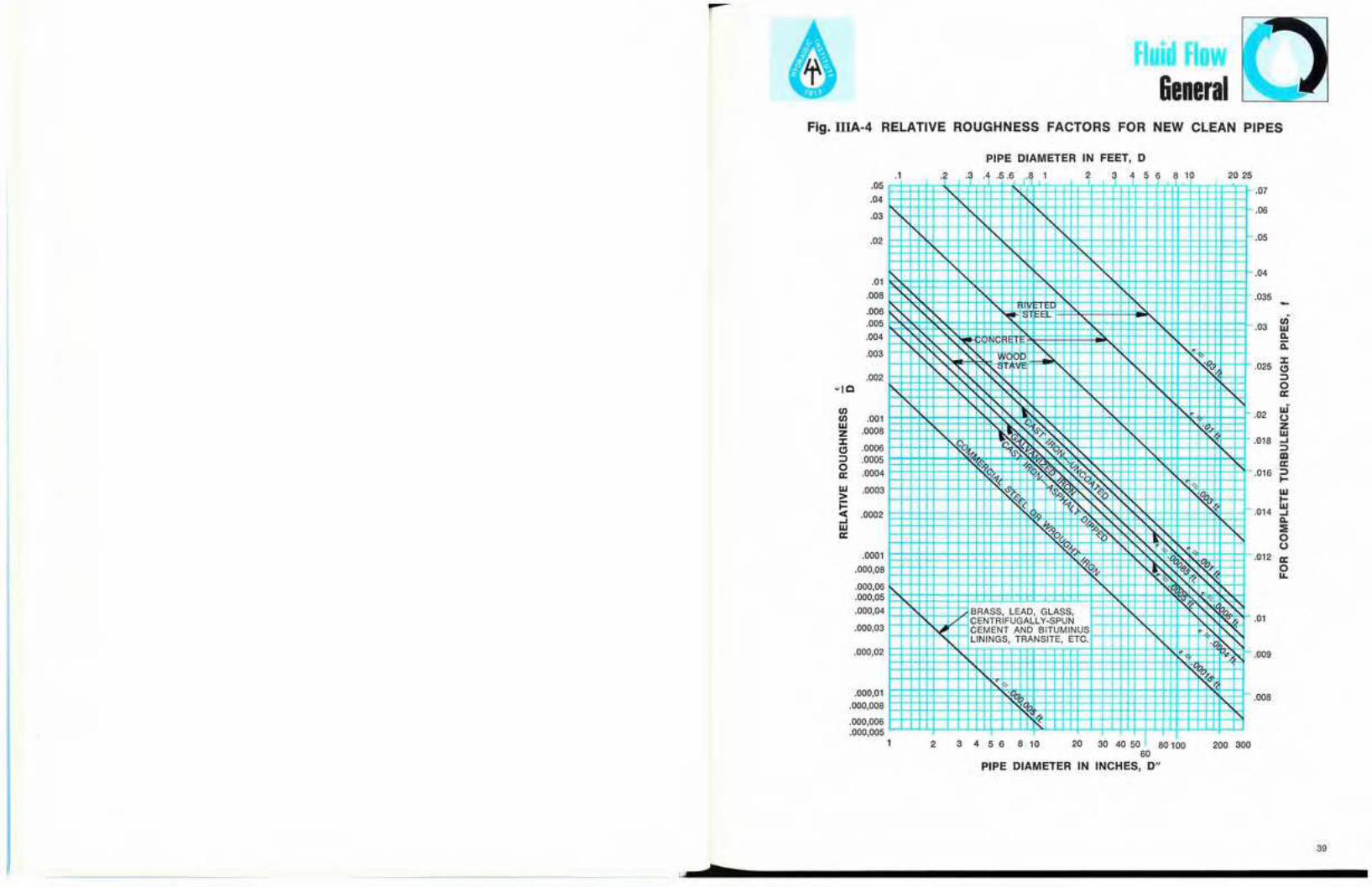
Fluid FlowGeneral
Fig. IIIA·4 RELATIVE ROUGHNESS FACTORS FOR NEW CLEAN PIPES
PIPE DIAMETER IN FEET, D
.01
.07
.06
.05
.04
.035 -
.03IIIIIJDo.ii:
.025:I:III::J0a:
.02 uiUZIIJ
.018 ..J::JIIIa:
.016 ::JI-IIJI-
.014IIJ..JDo.:::;:0U
.012 a:0...
.009
.008
1 a
.1 .3 A .5.6 1 2 3 4 6 8 10 20 25
セ
r'\. i'\ "'-
II'\. I cc'
I, C'
•セ
, ,,A ,
r-. セ セ
I'-. "-7-
.(;1;G
,
セZGZZ・セ 'fl"GセTゥ
,J>- 0.'fI "., ゥ v セ セ n ^
L L セ
N '1\:' a1.: (1, . 1',."
G('l <:i G
0/ r'\.N' A セ L
/,,p N セ N C2
"I"- ,:.../;.....1'- "(. ll>&
セ,BRASS. LEAD, GLASS.CENTRIFUGALLY-SPUN I'-. ,.....
vi CEMENT AND BITUMIN US I.: 1'-.'LININGS, TRANSITE, ETC.
セ•
Gセ
iGセ "'.•'?
{(.
1 2 3 4 5 6 8 10 20 30 40 50 80 a 200 300
.05
.04
.03
.02
.01
.008
.006
.005
.004
.003
.002-10
IIIIII .001IIJ
.0008Z:I:III .0006::J .00050
.0004a:IIJ .0003>i=<I: .0002..JIIJa:
.0001
.000,08
.000,06
.000,05
.000,04
.000,03
.000,02
.000,01
.000,008
.000,006
.000,005
60
PIPE DIAMETER IN INCHES, D"
39ャ セ _

Fluid Flow&eneral
Fluid Flow&eneral
SUDDEN ENLARGEMENTA'2=oo; A 1/A 2 ==O.
PRESSURE TANK
I
2 ELBOWS-R/D<1
1-\-27'\ - \ WEDGE-DISC\ GATE VALVE
SQUARE EDGED INLET
ELEV, 67,0'
Fig. IIIA·6 INSTALLATION FOR EXAMPLE No.1
--------------- I
MMMMゥセセセセセゥセョZエNセ]セエZ]ZZZ]ZZZSイe]]ZZZセNNjeセlQセvLQVRセP]MoGMMMMMヲセッTMGUP PSI
OPEN TANK T
ALL PIPE IS NEW 2-INCH STEEL SCHEDULE 40
00
'" u:0 <Il0 W
'" W0 0:0
"'" w0
00 wセ
0 0:
'" :::>0 I-
'" ...0:
0 W... l>.0 :E'" w0 I-
'"0
0セ
00000
C;CD<OI.O-q-M
ogo
.- co UHf)...,. CO) (\I000000 a000000 0、セセセセセ セ00000 0
':>3S 1I3d G Q セ 'OS 'AJ.ISO:>SIII :>11VW3NI)I
セ c d (Oll),<:" M N000000 a」ゥセ セアア f::! 000000 c:::i
'"oo
000000 0セ」ッ (01l')'V (") N
ooo
'"
(, I I I I I I ,000000 0000000 0セ co <0 l,() '<t c? C\l
S3>10.LSI.LN30 'A.LISOOSIA OI.LVIt\l3NI>I
I! l. I I I I e I ,o IX) «)to '<t C') Nセ ci ci ci ci ci c:i
4041
セMMMMMMMMMMMMMMMMMMMMM

Fluid Flow&eneral
Fluid FlowFriction Loss -Water
Fig. IlIA·? INSTALLATION FOR EXAMPLE No.2 I1IB·1-FRICTION LOSS-WATER
Pd
= (293 - 2) x 62.34 = 126 psi144
*(NOTE: It is preferable to use FIg. IIIA-5 for flanged elbowsR
when the - ratio Is greater than unity. The use of Fig. IIlA-5D
is illustrated in Section lilA, Example 4.)
V'h = k - =3.79 x 0.4052g
= 1.53 feet
The pump must raise the water from elevation28.62 to elevation 289.00. Therefore, the dischargehead will be
hd = (289.00 - 28.62) + 1.53 + 34.25'" 296 feet
The pressure head in the discharge pipe at thepoint where the pressure gauge is attached will beequal to the static head plus the friction losses inthe discharge pipe minus the velocity head. Thestatic head = 265 - 7 = 25lJ feet. The other quan-tities have been computed above. Therefore, therequired pressure head = 258 + 1.53 + 34.25 -0.405 '" 293 feet. The pressure head at the centerof the gauge will be 2 feet less than this valuebecause of the 2-foot vertical connection. The spe-cific weight of water at 60° F is 62.34 pounds percubic foot from Section !lA. Therefore, the read-ing of the discharge pressure gauge will be
k = 2 x 0.31 + 2 + 0.17 + 1.0= 3.79
and, by Equation (4), Section lIlA, the head lossdue to the fittings will be
follows:
'Regular flanged elbOW, k = 0.31Swing check valve, k = 2.0Wedge-disc gate valve, k = 0.17Sudden enlargement, k = 1.0
The total resistance coefficient for the fittings willbe
b. Discharge Line. The head loss due to pipe fric-tion in the discharge line will be
1250h, = 2.74 -- = 34.25 feet
100
The resistance coefficients for the fittings may beobtained from Tables 32(a), 32(b) and 32(c), as
V2h=k-
2g= (0.8 x 0.405)
= 0.324 feet
The pump must raise the water from elevation24.00 to elevation 28.62. Therefore, the suction liftwill be
h, = (28.62 - 24.00) + 0.32 + 0.14 = 5.08 feet.
SOLUTION: a. Suction Line. The following informa-tion may be obtained from Table 13 for a flow of200 gallons per minute:
V'Velocity head - = 0.405 feet, 2g
Pipe friction loss, h, = 2.74 feet per 100 feet ofpipe.
The resistance coefficient for the foot valve may beobtained from Tables 32(b) and 32(c):
Foot valve, k = 0.8
The head loss due to pipe friction will be
5hi = 2.74 - = 0.14 feet
100
and, by Equation (4), Section IlTA, the head lossin the foot valve will be
Example 3. Use of Tables for Water. A pumpdraws water (60° F) from a sump and delivers itto an elevated tank through 1250 feet of new 4-inchdiameter asphalt-dipped cast iron pipe (See Fig.IIIB-1).The suction pipe is vertical, 5 feet long andequipped with a foot valve. The discharge pipecontains two regular 90 degree flanged elbows
with セ = 1.4, a swing check valve, and an openD
wedge-disc gate valve. It is required to find thesuction lift (hJ, the discharge head (h,I), and thereading of the discharge pressure gauge (Pd),when the rate of flow is 200 gallons per minute.
60'
--ELEV. 127.00'
ALL DISCHARGE VALVES 8" WEDGE- ISC GATES
HEATER350'F.40 PSI
PRESSUREDROP
7W x 3%" VENTURI METER-Co = 0.98
8" TO 6" REDUCING ELBOW11.75" RADIUS
ECONOM i z e r M M M M M M M M M M M M i セ M M -_M セ セ ⦅ [ [ [ L Z [ [ セ M ] ⦅AND BOILER900 PSI GA.
PRESSURE REGULATOR
-50 PSI PRESSURE DROP
セセ]ZXZBZsZcZhIedule 80 STEEL PIPE2-90' BENDS-50" RADIUS
10"SCHEDULE 40STEEL PIPE
セN
セセ
<,<:\/'ALL DISCHARGE ELBOWS/' 8"-11.75" RADIUS
TOTAL LENGTH OF SUCTION PIPE 230 FT. INCLUDING FITTINGSTOTAL LENGTH OF 250' DISCHARGE PIPE 108 FT. INCLUDING FITTINGSTOTAL LENGTH OF 350° DISCHARGE PIPE 165 FT. INCLUDING FITTINGS
,.....--DIRECT CONTACT HEATER30 PSI ABSOLUTE-250'F.
..........""" ......,.1 ELEV. 132.00' MINIMUM WATER LEVEL
L SUCTION VALVES" WEDGE-DISC GATES
。 セ ョ i f ] ゥ
65'
ELEV. 67.00' CENTERLINE PUMP
10" TO 8" REDUCING ELBOWJ9.5" RADIUS
42 43
______________________________-l.Jrrr _

Fluid FlowFriction Loss -Water
Fluid FlowFriction Loss- Water
Fig. illB-2-FRICTION LOSS FOR WATER IN FEET PER FOOT OFSTAINLESS STEEL TUBING AND IN FEET FOR SANITARY FITTINGS.
-SUMP
FIG. I1IB-1 INSTALLATION FOR EXAMPLE NO.3 Je.apacit 0.0.-1" 0.0.-1%" 0.0.-2" 0.0. 21/2" 0.0. 3" 0.0. 4"in U.S.
1.0.- 1.870" 1.0. 2.370" 1.0. 2.870" 1.0. 3.834"G.P.M. 1.0.- 0.902" 1.0.- 1.402"Tubing Elbow T.. Tubing Elbow T.. Tubing Elbow T.. Tubint Elbow T.. Tubing Elbow T.. Tubing Elbow T..
2 .01 .01 .I4 .025 .02 .2
5 .035 .025 .25
10 .12 .05 .4 .02 .01 .15 .005 .015 .1
15 .25 .I .8 .04 .02 .25 .013 .02 .IS20 .43 .22 1.5 .06 .03 .3 .02 .025 .2 .005 .02 .1 .003 .02 .06
25 .66 .4 2.3 .08 .04 .4 .025 .03 .25 .006 .03 .15 .004 .03 .08
30 .93 .7 3.3 .IDS .06 .55 .035 .05 .3 .008 .05 .2 .005 .04 .I35 1.22 1.25 5.2 .135 .09 .8 .04 .06 .4 .011 .06 .25 .006 .05 .13
40 .17 .11 1.0 .05 .08 .5 .015 .07 .3 .007 .06 .IS45 .21 .16 1.3 .063 .I .6 .02 .09 .35 .008 .065 .18
50 .25 .2 1.6 .073 .12 .7 .022 .I .4 .01 .07 .2
60 .34 .35 2.2 .I .18 .9 .03 .12 .45 .015 .08 .25
80 .57 .76 3.7 .16 .3 1.5 .05 .IS .55 .02 .1 .4100 .85 1.35 5.8 .23 .44 2.3 .075 .18 .6 .03 .II .5 .008 .04 .I120 1.18 2.05 9.1 .32 .64 3.3 .105 .21 1.0 .04 .13 .6 .01 .05 .IS140 .42 .85 4.5 .14 .23 1.25 .05 .16 .8 .013 .06 2
160 .54 1.13 5.8 .17 .28 1.6 .07 .2 1.1 .015 .07 .25
180 .67 1.45 7.4 .205 .31 2.0 08 .21 1.3 .02 .08 .3
200 .81 1.82 9.0 .245 .35 2.5 .1 .26 1.6 .025 .09 .4
220 .95 2.22 11.0 .29 .41 3.0 .12 .3 1.9 .028 .I .5
240 1.10 2.63 13.5 .34 .48 3.7 .14 .33 2.2 .035 .II .55
260 .39 .53 4.5 .165 .39 2.5 .04 .lIS .6
280 .45 .61 5.3 .19 .42 2.8 .045 .12 .65
300 .515 .7 6.2 .22 .5 3.1 .05 .13 .7
350 .68 1.05 8.5 .28 .67 4.1 .07 .IS .9400 .86 1.55 11.0 .36 .88 5.2 .085 .18 1.2
450 1.05 2.25 13.5 .44 1.1 6.6 .105 .2 1.5500 .54 1.4 8.0 .13 .23 1.75550 .64 1.7 9.5 .15 .27 2.1600 .75 2.05 10.2 .175 .3 2.5
6'0 .87 2.41 13.0 .2 .34 2.8700 1.0 ... 2.8 15.0 .23 .4 3.4750 .26 .43 3.8800 .3 .5 4.4850 .33 .56 5.0900 .37 .62 5.7950 .41 .7 6.3
1000 .45 .8 7.01100 .53 1.06 8.6
ELBOW-5W' RAD.
SUDDENENLARGEMENT
A,= 00 A,/A,=O
OPEN TANK
ELEV. 289. •
1250'
l\;;"_-- DISCHARGE PRESSURE GAGE
'-FOOT VALVE
ALL PIPE IS NEW 4-INCH ASPHALT-DIPPED CAST IRON
i]ZZャ]⦅]⦅]⦅M]MZセM]]]M ELEV. 24.00'
265'
NOTES: 1. FOR ELBOWS - RID = 1.5
2. FLOW THRU TEES-FLOW A TO BPORT C CAPPED OFF.
3. TEST MEDIUM - WATER AT 70' F
A Reprinted withpermission from theDairy and FoodIndustries SupplyAssociation, Inc.
4445
_____________M M M j A セ _
z::Eセ...Ioowa.a.ca:<czセII)
a:oLL
....a:<:I:oII)II)
o...I
Zoi=oa:LL
セ
CIS-M•mSClii:
47
ooM
oo
o:5::E
0-0":5 1
セ0-oC)セ B 0-
"C)
Fluid FlowFriction Loss -Water
HEAD LOSS PER 100 FT OF COLUMN-FT
1"'-'"""- LLセセ '"'" セセ イZZZZセセ セ.., R
a'<'];
セLMFMLN 00
"- f' f::: '::::: ::::::- セ セ GXセセ0
セセ -'c", セセ 0
0,セ セ セセ BMセエM
0
f:::" I""-'セ
I't'-- r::s..'f::>セセ セ t-"-セ r:: f' j:::f::: セセセセ セセ
セ セi GGGMG」ャLヲZウセセセI'p:::セセ
f'1'-J'--...1'- I'-...
セ , セ セィB セセ{ZZ[ZZZ エZZZセセセ ,"-I'-... セ セ セ セ 1':---- セセ
セ , I'"'""r:::: ["'---... 1'--, '0-'c' セ I' "- r.::t::::;::GoMG」Bセセ "-
セ L L セ i"-r----. I"---- セ.1-1" I 1"--['-... t:::I"--.- セ f'-.-.. "- I"-
1'-. I'-...
'"'""f' i'---
'"'"" '"'"" '"'"""'-,
'"'"" " i"-- セ "'- ....1'-N."'""1'-,"- " ....
セ "'"" '"""- 8 " I.... i"-- " セi"-- -'c", I'
1,,- '"""- "- " "" "" '"'"". iセ I'-....... ,........セ........
I"""" " "-
"" "" ....... ?-'c 1,"",,- セセ ............... セ
セI...... NNNNセ "'- ""-?
l セ セ1"-1'-,
........ -'c", "-I"- "'- ........ " I'1'-.
セ r::: iGMセ '"'""8-'c ,.......
セf'1' i"---r:::f::: セ セ セi 8:: セ f' I"-......
iセI'- i B セ .......G::: "8-'c ''''' セ f'i
I"-- "'-!' i G M セ セ
セ ウ <J;
"'- f'1' I"---.l'- セ -'c" 1"-1"- I'-- r-......1'-.... J"::: S -\- セ
f' ........ セMG」 'セセ "-r----.I"-
セ f' ........セ I'-... セセ "- I"-"'-I...... " ]MGセ セセ f' "-セ ャ G M M N N N N "-c ,;, "- I'--l"-f'
セ i' I"-r----. "-I"--" { B N N N N N N N N セ ェ セ M G 」 I"-r----."'"'"""- <' cf .--" ....... " r....
....... '.he .......... " 1'....
I' ,......." "'- 1'"""- ....r---- I'"" t:-.....
'"-'r '.k- セ L N N N N N N N I" ","N セ
...........-'c,
1"'- "" f'f'....... '""- " I'--.......
....r----. I"---.セ "1""--" -'c " I' "'-
I"-Gセ I"-
セ l"- t.......セ m m セ セ
Reprinted from AWWA Standard El01-71 bypermission of the Association. Copyrighted 1971by the American Water Works Association, Inc.,6666 West Quincy Ave" Denver, Colorado 80235
column and the inner shaft enclosing tube). For theouter pipe columns, the calculations used in con-structing the chart were based on inside diameters,which are closest to the nominal size for pipe up toand including 12 inches, (for example, 10 inch =10.2 inch inside diameter); in sizes 14 inches andlarger the diameters shown are equivalent to theoutside diameter of pipe with 3/B inch wall thick-ness (for example, 16 inch = 15% inch insidediameter). For the inner columns (shaft-enclosingtubes), the calculations were based on the outsidediameters of standard or extra-heavy pipe. Thus,"8 x 2" on the chart is actually 8.071 x 2318, and16 x 3 is 15% x 3%.
mated average losses. Where extreme accuracy isimperative, actual loss measurements in the dis-charge head to be used-with the correct tubing orshaft, column, and discharge pipe-should bespecified on the bid request by the purchaser.
Fluid FlowFriction Loss -Water
IIIB-3 FRICTION LOSSES IN DEEP WELL VERTICAL TURBINE PUMP COLUMNSAND DISCHARGE HEADS
Discharge Head Loss
The discharge head loss chart Fig. IlIB-3(b) shouldbe used to determine the hydraulic losses in thedischarge head. Losses in discharge heads varywith the size of the head, the design of the head,and the size of tubing or shaft, column and dis-charge pipe used. Fig. IIIB-3(b) represents esti-
Column Friction LossThe column friction chart Fig. IIIB-3(a) should beused to determine the loss in head due to columnfriction. This chart has been compiled from data onhead losses where the flow is between the insidediameter of the column pipe and the outside diam-eter of the shaft-enclosing tube.
For open line shafting, the losses shown on Fig.IIIB-3should be used by assuming the losses equalto those indicated on the chart for a shaft-enclosingtube of a size that would normally enclose the openline shaft in question.
The diagonals on Fig. IIIB-3(a) are labeled to shownominal diameters (in inches of the outer pipe
46
iiiiiiiiiiiiiiiiiiiiiiiiiiiiiiiiiiiiiiiiiiiiiiiiiiiiiiiiiiiiiiiiiiiiiiiiiiiiiiiiiiiiiiiiiiiiiiiiii セ -'-dt 4

Fluid FlowFriction Loss -Water
Fluid FlowFriction Loss -Water
I1IB-4 FRICTION LOSS FOR WATER IN FEET PER 100 FEET OF PIPE
Fig. I1IB-3(b) HEAD LOSS IN DISCHARGE HEADSTABLE 1 TABLE 2
STEEL SCHEDULE 40Y4INCH ID = 0.364 INCHES
NOMINAL folD = 0.00495
DISCHARGE hrV V2/2g feet per 100
CFS GPM ft/sec feet feet of pipe0.000111 0.05 0.154 0.000369 0.2030.000223 0.10 0.308 0.001477 0.4050.000334 0.15 0.462 0.00332 0.6080.000446 0.20 0.617 0.00591 0.8100.000557 0.25 0.771 0.00923 1.013
TRANSITION TO TURBULENT FLOW0.000891 0.4 1.23 0.0236 3.70.00134 0.6 1.85 0.0532 7.60.00178 0.8 2.47 0.0946 12.70.00223 1.0 3.08 0.1477 19.10.00267 1.2 3.70 0.213 26.7
0.00312 1.4 4.32 0.290 35.30.00356 1.6 4.93 0.378 45.20.00401 1.8 5.55 0.479 56.40.00446 2.0 6.17 0.591 69.00.00557 2.5 7.71 0.923 105
0.00668 3.0 9.25 1.330 1480.00780 3.5 10.79 1.810 2000.00891 4.0 12.33 2.36 2590.0100 4.5 13.87 2.99 3260.0111 5.0 15.42 3.69 398
STEEL SCHEDULE 40Va INCH ID = 0.269 INCHES
NOMINAL dO = 0.00669
DISCHARGE h rV V2/2g feet per 100
CFS GPM It/sec feet feet of pipe
.0000446 0.02 0.113 0.000198 0.272
.0000891 0.04 0.226 0.000792 0.543
.000134 0.06 0.339 0.00178 0.815
.000178 0.08 0.452 0.00317 1.087
.000223 0.10 0.565 0.00495 1.359
.000267 0.12 0.677 0.00713 1.630
.000312 0.14 0.790 0.00971 1.902
.000356 0.16 0.903 0.0128 2.174
.000401 0.18 1.02 0.0160 2.445
.000446 0.20 1.13 0.0198 2.717TRANSITION TO TURBULENT FLOW
.000668 0.3 1.69 0.0446 9.70
.000891 0.4 2.26 0.0792 16.2
.00111 0.5 2.82 0.124 24.2
.00134 0.6 3.39 0.178 33.8
.00156 0.7 3.95 0.243 44.8
.00178 0.8 4.52 0.317 57.4
.00201 0.9 5.08 0.401 71.6
.00223 1.0 5.65 0.495 87.0
.00267 1.2 6.77 0.713 122
.00312 1.4 7.90 0.971 164
.00356 1.6 9.03 1.28 212
.00401 1.8 10.2 1.60 265
.00446 2.0 11.3 1.98 324
10,0004,0002,000700 1,00040020060 60 1004020
0
8 -1-!/ / / I
6 I / / 'I II I II I I I I I
4I I II I I I 1/
/ / II I I II I II I
1/ 1/ 1/ 1/ IIII I I 1//'I 1/ I
2
/ / / 111/IIII
II!l'i 1//1/
1'I
I0 I I8
/ -I-ff /
6 I I I I I I I I II I I II I I I I I I
4 I I I II I II II I I IIv / / I / '/ I II II I / I / /
IIIII II
/'/ I rl I 1/ I2 " I
>'0'
Bセ[Zy[ Vi / / I
iOセvセN /<0-' /
セセ セ '" 'I '" tiD0 セオ Is
8/ 1/
6 I I I I I / II I II I I I I I II I II II I
II II I I I I/ I 'I II II I I II I I I 1/
/ !/ / /IIIIII I 'I II
I
/ II,I / II I III!lij 1/ 1/
/ 1/I
o.
o.
1.
O.
o.
0.0
0.1
0.0
0.04
0,0110
0.02
CAPACITY-GPM
NOTE: No allowance has been made for age, differences in diameter, or any abnormal condition of interior surface. Any factorof safety must be estimated from the local conditions and the requirements of each particular installation.
46
セ49
--------------------------------------------------_...'- .

Fluid FlowFriction Loss -Water
Fluid FlowFriction Loss- Water
IIIB-4 FRICTION LOSS FOR WATER IN FEET PER 100 FEET OF PIPE IIIB-4 FRICTION LOSS FOR WATER IN FEET PER 100 FEET OF PIPE
TABLE 3
STEEL SCHEDULE 40% INCH 10 セ 0.493 INCHES
NOMINAL dO = 0.00365
DISCHARGE h,V V212g feet per 100
CFS GPM ft/sec feet feet of pipe0.00134 0.6 1.01 0.0158 1.740.00178 0.8 1.34 0.0281 2.890.00223 1.0 1.68 0.0440 4.300.00334 1.5 2.52 0.0988 8.930.00446 2.0 3.36 0.176 15.0
0.00557 2.5 4.20 0.274 22.60.00668 3.0 5.04 0.395 31.80.00780 3.5 5.88 0.538 42.60.00891 4.0 6.72 0.702 54.90.0100 4.5 7.56 0.889 68.4
0.0111 5.0 8.40 1.097 83.50.0123 5.5 9.24 1.33 1000.0134 6.0 10.08 1.58 1180.0149 6.5 10.9 1.85 1370.0156 7.0 11.8 2.15 158
0.0167 7.5 12.6 2.47 1810.0178 8.0 13.4 2.81 2050.0189 8.5 14.3 3.17 2310.0201 9.0 15.1 3.56 2560.0212 9.5 16.0 3.96 2860.0223 10.0 16.8 4.39 316
TABLE 4
STEEL SCHEDULE 40
* INCH 10 = 0.622 INCHESNOMINAL <10 = 0.00289
DISCHARGE h,V V212g feet per 100
CFS GPM ft/sec feet feet of pipe0.00156 0.7 0.739 0.00849 0.7400.00223 1.0 1.056 0.0173 1.860.00334 1.5 1.58 0.0390 2.850.00446 2.0 2.11 0.0693 4.780.00557 2.5 2.64 0.1083 7.16
0.00668 3.0 3.17 0.156 10.00.00780 3.5 3.70 0.212 13.30.00891 4.0 4.22 0.277 17.10.0100 4.5 4.75 0.351 21.30.0111 5.0 5.28 0.433 25.8
0.0123 5.5 5.81 0.524 30.90.0134 6.0 6.34 0.624 36.50.0149 6.5 6.86 0.732 42.40.0156 7.0 7.39 0.849 48.70.0167 7.5 7.92 0.975 55.5
0.0178 8.0 8.45 1.109 62.70.0189 8.5 8.98 1.25 70.30.0201 9.0 9.50 1.40 78.30.0212 9.5 10.03 1.56 86.90.0223 10.0 10.56 1.73 95.9
0.0245 11.0 11.6 2.10 1150.0267 12.0 12.7 2.49 1360.0290 13.0 13.7 2.93 1590.0312 14.0 14.8 3.40 1830.0334 15.0 15.8 3.90 209
TABLE 5
STEEL SCHEDULE 40:y, INCH 10 セ 0.824 INCHESNOMINAL <10 = 0.00218
DISCHARGE h,V V2/2g feet per 100
CFS GPM ft/sec feet feet of pipe
0.00223 1.0 0.602 0.00563 0.2600.00334 1.5 0.903 0.0127 0.7300.00446 2.0 1.20 0.0225 1.210.00557 2.5 1.50 0.0352 1.800.00668 3.0 1.81 0.0506 2.50
0.00780 3.5 2.11 0.0689 3.300.00891 4.0 2.41 0.0900 4.210.0100 4.5 2.71 0.114 5.210.0111 5.0 3.01 0.141 6.320.0134 6.0 3.61 0.203 8.87
0.0156 7.0 4.21 0.276 11.80.0178 8.0 4.81 0.360 15.00.0201 9.0 5.42 0.456 18.80.0223 10 6.02 0.563 23.00.0245 11 6.62 0.681 27.6
0.0267 12 7.22 0.810 32.60.0290 13 7.82 0.951 37.80.0312 14 8.42 1.103 43.50.0334 15 9.03 1.27 49.70.0356 16 9.63 1.44 56.3
0.0379 17 10.23 1.63 63.10.0401 18 10.8 1.82 70.30.0423 19 11.4 2.03 78.00.0446 20 12.0 2.25 86.10.0490 22 13.2 2.72 104
0.0535 24 14.4 3.24 1220.0579 26 15.6 3.80 1430.0624 28 16.8 4.41 1640.0668 30 18.1 5.06 187
TABLE 6
STEEL SCHEDULE 401 INCH 10 = 1.049 INCHES
NOMINAL flO = 0.00172
DISCHARGE hiV V2/2g feet per 100
CFS GPM ft/sec feet feet of pipe
0.00267 1 0.371 0.00214 0.1140.00446 2 0.742 0.00857 0.3790.00668 3 1.114 0.01927 0.7720.00891 4 1.48 0.0343 1.2950.0111 5 1.86 0.0535 1.93
0.0134 6 2.23 0.0771 2.680.0156 7 2.60 0.1049 3.560.0178 8 2.97 0.137 4.540.0201 9 3.34 0.173 5.650.0223 10 3.71 0.214 6.86
0.0267 12 4.45 0.308 9.620.0312 14 5.20 0.420 12.80.0356 16 5.94 0.548 16.50.0401 18 6.68 0.694 20.60.0446 20 7.42 0.857 25.1
0.0490 22 8.17 1.036 30.20.0535 24 8.91 1.23 35.60.0579 26 9.65 1.45 41.60.0624 28 10.39 1.66 47.90.0668 30 11.1 1.93 54.6
0.0713 32 11.9 2.19 61.80.0758 34 12.6 2.48 69.40.0802 36 13.4 2.78 77.40.0847 38 14.1 3.09 86.00.0891 40 14.8 3.43 95.0
0.0936 42 15.6 3.78 104.50.0980 44 16.3 4.15 1140.102 46 17.1 4.53 1240.107 48 17.8 4.93 1350.111 50 18.6 5.35 146
0.123 55 20.4 6.48 1760.134 60 22.3 7.71 2090.145 65 24.1 9.05 2450.156 70 26.0 10.49 2830.167 75 27.8 12.0 324
0.178 80 29.7 13.7 3670.189 85 31.6 15.5 4130.201 90 33.4 17.3 4620.212 95 35.3 19.3 5130.223 100 37.1 21.4 567
NOTE: No allowance has been made for age, differences in diameter, or any abnormal condition of interior surface. Any factorof safety must be estimated from the local conditions and the requirements of each particular installation.
50
NOTE: No allowance has been made for age, differences In diameter, or any abnormal condition of interior ウ オ イ セ 。 」 ・ N Any factorof safety must be estimated from the local conditions and the requirements of each particular installation.
51Jz -

Fluid FlowFriction Loss-Water
Fluid FlowFriction Loss-Water
IIIB·4 FRICTION LOSS FOR WATER IN FEET PER 100 FEET OF PIPE IIIB-4 FRICTION LOSS FOR WATER IN FEET PER 100 FEET OF PIPE
TABLE 7
STEEL SCHEDULE 401¥. INCH 10 =1.380 INCHESNOMINAL dO =0.00130
DISCHARGE h,V V2/2g feet per 100
CFS GPM ft/sec feet feet of pipe
0.00334 1.5 0.322 0.00161 0.06230.00446 2 0.429 0.00286 0.1020.00668 3 0.644 0.00644 0.2070.00891 4 0.858 0.01144 0.3420.0111 5 1.073 0.0179 0.508
0.0134 6 1.29 0.0257 0.7040.0156 7 1.50 0.0350 0.9300.0178 8 1.72 0.0458 1.180.0201 9 1.93 0.0579 1.460.0223 10 2.15 0.0715 1.77
0.0267 12 2.57 0.103 2.480.0312 14 3.00 0.140 3.280.0356 16 3.43 0.183 4.200.0401 18 3.86 0.232 5.220.0446 20 4.29 0.286 6.34
0.0490 22 4.72 0.346 7.580.0535 24 5.15 0.412 8.920.0579 26 5.58 0.483 10.370.0624 28 6.01 0.561 11.90.0668 30 6.44 0.644 13.6
0.0713 32 6.86 0.732 15.30.0758 34 7.29 0.827 17.20.0802 36 7.72 0.927 19.20.0847 38 8.15 1.032 21.30.0891 40 8.58 1.14 23.5
0.0936 42 9.01 1.26 25.80.0980 44 9.44 1.38 28.20.102 46 9.87 1.51 30.70.107 48 10.30 1.65 33.30.111 50 10.7 1.79 36.0
0.123 55 11.8 2.16 43.20.134 60 12.9 2.57 51.00.145 65 13.9 3.02 59.60.156 70 15.0 3.50 68.80.167 75 16.1 4.02 78.7
0.178 80 17.2 4.58 89.20.189 85 18.2 5.17 100.20.201 90 19.3 5.79 1120.212 95 20.4 6.45 1240.223 100 21.5 7.15 138
0.245 110 23.6 8.65 1660.267 120 25.7 10.3 1970.290 130 27.9 12.1 2300.312 140 30.0 14.0 2670.334 150 32.2 16.1 306
TABLE 8
STEEL SCHEDULE 401'12 INCH 10 = 1.610 INCHESNOMINAL dO = 0.00112
DISCHARGE h,V V2/2g feet per 100
CFS GPM ft/sec feet feet of pipe
0.00334 1.5 0.236 0.000868 0.03000.00446 2 0.315 0.00154 0.04920.00668 3 0.473 0.00347 0.09880.00891 4 0.630 0.00618 0.1640.0111 5 0.788 0.00965 0.242
0.0134 6 0.946 0.0139 0.3330.0156 7 1.103 0.0189 0.4390.0178 8 1.26 0.0247 0.5580.0201 9 1.42 0.0313 0.6890.0223 10 1.58 0.0386 0.829
0.0267 12 1.89 0.0556 1.160.0312 14 2.21 0.0756 1.530.0356 16 2.52 0.0988 1.960.0401 18 2.84 0.125 2.420.0446 20 3.15 0.154 2.94
0.0490 22 3.47 0.187 3.520.0535 24 3.78 0.222 4.140.0579 26 4.10 0.261 4.810.0624 28 4.41 0.303 5.510.0668 30 4.73 0.347 6.26
0.0713 32 5.04 0.395 7.070.0758 34 5.36 0.446 7.920.0802 36 5.67 0.500 8.820.0847 38 5.99 0.577 9.780.0891 40 6.30 0.618 10.79
0.0936 42 6.62 0.681 11.80.0980 44 6.93 0.747 12.90.102 46 7.25 0.817 14.00.107 48 7.56 0.889 15.20.111 50 7.88 0.965 16.4
0.123 55 8.67 1.17 19.70.134 60 9.46 1.39 23.20.145 65 10.24 1.63 27.10.156 70 11.03 1.89 31.30.167 75 11.8 2.17 35.8
0.178 80 12.6 2.47 40.50.189 85 13.4 2.79 45.60.201 90 14.2 3.13 51.00.212 95 15.0 3.48 56.50.223 100 15.8 3.86 62.2
0.245 110 17.3 4.67 74.50.267 120 18.9 5.56 88.30.290 130 20.5 6.52 1030.312 140 22.1 7.56 1190.334 150 23.6 8.68 137
0.356 160 25.2 9.88 1560.379 170 26.8 11.15 1750.401 180 28.4 12.50 1960.423 190 29.9 13.9 2180.446 200 31.5 15.4 241
TABLE 9
STEEL SCHEDULE 402 INCH 10 = 2.067 INCHES
NOMINAL dO セ 0.00087
DISCHARGE h,V V2/2g feet per 100
CFS GPM ftlsec feet feet of pipe
0.00446 2 0.191 0.000568 0.01510.00668 3 0.287 0.00128 0.03020.00891 4 0.382 0.00227 0.04970.0111 5 0.478 0.00355 0.07310.0134 6 0.574 0.00511 0.1004
0.0156 7 0.669 0.00696 0.1310.0178 8 0.765 0.00909 0.1660.0201 9 0.860 0.0115 0.2050.0223 10 0.956 0.0142 0.2480.0267 12 1.15 0.0205 0.343
0.0312 14 1.34 0.0278 0.4530.0356 16 1.53 0.0364 0.5780.0401 18 1.72 0.0460 0.7170.0446 20 1.91 0.0568 0.8680.0490 22 2.10 0.0688 1.03
0.0535 24 2.29 0.0818 1.200.0579 26 2.49 0.0960 1.390.0624 28 2.68 0.111 1.600.0668 30 2.87 0.128 1.820.0780 35 3.35 0.174 2.42
0.0891 40 3.82 0.227 3.100.100 45 4.30 0.288 3.850.111 50 4.78 0.355 4.670.123 55 5.26 0.430 5.590.134 60 5.74 0.511 6.59
0.145 65 6.21 0.600 7.690.156 70 6.69 0.696 8.860.167 75 7.17 0.799 10.10.178 80 7.65 0.909 11.40.189 85 8.13 1.03 12.8
0.201 90 8.60 1.15 14.20.212 95 9.08 1.28 15.80.223 100 9.56 1.42 17.40.245 110 10.52 1.72 20.90.267 120 11.5 2.05 24.7
0.290 130 12.4 2.40 28.80.312 140 13.4 2.78 33.20.334 150 14.3 3.20 38.00.356 160 15.3 3.64 43.00.379 170 16.3 4.11 48.4
0.401 180 17.2 4.60 54.10.423 190 18.2 5.13 60.10.446 200 19.1 5.68 66.30.490 220 21.0 6.88 80.00.535 240 22.9 8.18 95.0
0.579 260 24.9 9.60 1110.624 280 26.8 11.14 1280.668 300 28.7 12.8 1460.713 320 30.6 14.5 1660.758 340 32.5 16.4 187
0.802 360 34.4 18.4 2090.847 380 36.3 20.5 2330.891 400 38.2 22.7 258
TABLE 10
STEEL SCHEDULE 402'h INCH 10 セ 2.469 INCHESNOMINAL dO = 0.000729
DISCHARGE h,V V2/2g feet per 100
CFS GPM ft/sec feet feet of pipe
0.00668 3 0.201 0.000628 0.01290.00891 4 0.268 0.00112 0.02130.0134 6 0.402 0.00251 0.04320.0178 8 0.536 0.00447 0.07120.0223 10 0.670 0.00698 0.105
0.0267 12 0.804 0.0100 0.1450.0312 14 0.938 0.0137 0.1910.0356 16 1.07 0.0179 0.2430.0401 18 1.21 0.0226 0.3000.0446 20 1.34 0.0279 0.362
0.0490 22 1.47 0.0338 0.4300.0535 24 1.61 0.0402 0.5020.0579 26 1.74 0.0472 0.5800.0624 28 1.88 0.0547 0.6630.0668 30 2.01 0.0628 0.753
0.0780 35 2.35 0.0855 1.000.0891 40 2.68 0.112 1.280.100 45 3.02 0.141 1.600.111 50 3.35 0.174 1.940.123 55 3.69 0.211 2.32
0.134 60 4.02 0.251 2.720.145 65 4.36 0.295 3.160.156 70 4.69 0.342 3.630.167 75 5.03 0.393 4.130.178 80 5.36 0.447 4.66
0.189 85 5.70 0.504 5.220.201 90 6.03 0.565 5.820.212 95 6.37 0.630 6.450.223 100 6.70 0.698 7.110.245 110 7.37 0.844 8.51
0.267 120 8.04 1.00 10.00.290 130 8.71 1.18 11.70.312 140 9.38 1.37 13.50.334 150 10.05 1.57 15.40.356 160 10.7 1.79 17.4
0.379 170 11.4 2.02 19.60.401 180 12.1 2.26 21.90.423 190 12.7 2.52 24.20.446 200 13.4 2.79 26.70.490 220 14.7 3.38 32.2
0.535 240 16.1 4.02 38.10.579 260 17.4 4.72 44.50.624 280 18.8 5.47 51.30.668 300 20.1 6.28 58.50.780 350 23.5 8.55 79.2
0.891 400 26.8 11.2 1031.003 450 30.2 14.1 1301.114 500 33.5 17.4 1601.225 550 36.9 21.1 1931.337 600 40.2 25.1 230
NOTE: No allowance has been made for age, differences In diameter, or any abnormal condition of interior surface. Any factorof safety must be estimated from the local conditions and the requirements of each particular installation.
52
•
NOTE: No allowance has been made for age, differences In diameter, or any abnormal condition of interior surface. Any factorof safety must be estimated from the local conditions and the requirements of each particular Installation.
53
•

Fluid FlowFriction Loss -Water
Fluid FlowFriction Loss-Water
IllB-4 FRICTION LOSS FOR WATER IN FEET PER 100 FEET OF PIPETABLE 11
IIIB-4 FRICTION LOSS FOR WATER IN FEET PER 100 FEET OF PIPE
ASPHALT·DIPPEDSTEEL SCHEDULE 40 CAST IRON
3 INCH 10 セ 3.068 INCHES 10 セ 3.00 INCHESNOMINAL dO セ 0.000587 dO セ 0.00160
DISCHARGE h, h,V V2/2g feet per 100 V V2/2g feet per 100
CFS GPM It/sec feet feet of pipe ft/sec feet feet of pipe
0.0111 5 0.217 0.000732 0.0112 0.227 0.000800 0.01280.0223 10 0.434 0.00293 0.0372 0.454 0.00320 0.04350.0334 15 0.651 0.00659 0.0762 0.681 0.00720 0.09000.0446 20 0.868 0.0117 0.126 0.908 0.0128 0.15100.0557 25 1.085 0.0183 0.189 1.13 0.0200 0.2280
0.0668 30 1.30 0.0263 0.262 1.36 0.0288 0.3200.0780 35 1.52 0.0359 0.347 1.59 0.0392 0.4270.0891 40 1.74 0.0468 0.443 1.82 0.0512 0.5490.100 45 1.95 0.0593 0.547 2.04 0.0648 0.6830.111 50 2.17 0.0732 0.662 2.27 0.0800 0.830
0.123 55 2.39 0.0885 0.789 2.50 0.0968 0.9930.134 60 2.60 0.105 0.924 2.72 0.115 1.1700.145 65 2.82 0.124 1.07 2.95 0.135 1.360.156 70 3.04 0.143 1.22 3.18 0.157 1.560.167 75 3.25 0.165 1.39 3.40 0.180 1.78
0.178 80 3.47 0.187 1.57 3.63 0.205 2.020.189 85 3.69 0.211 1.76 3.86 0.231 2.280.201 90 3.91 0.237 1.96 4.08 0.259 2.550.212 95 4.12 0.264 2.17 4.31 0.289 2.820.223 100 4.34 0.2927 2.39 4.54 0.320 3.10
0.245 110 4.77 0.354 2.86 4.99 0.387 3.730.267 120 5.21 0.421 3.37 5.45 0.461 4.400.290 130 5.64 0.495 3.92 5.90 0.541 5.130.312 140 6.08 0.574 4.51 6.35 0.627 5.930.334 150 6.51 0.659 5.14 6.81 0.720 6.80
0.356 160 6.94 0.749 5.81 7.26 0.820 7.710.379 170 7.38 0.846 6.53 7.72 0.925 8.700.401 180 7.81 0.948 7.28 8.17 1.04 9.730.423 190 8.25 1.06 8.07 8.62 1.16 10.800.446 200 8.68 1.17 8.90 9.08 1.28 11.9
0.490 220 9.55 1.42 10.7 9.98 1.55 14.30.535 240 10.4 1.69 12.6 10.9 1.84 17.00.579 260 11.3 1.98 14.7 11.8 2.16 19.80.624 280 12.2 2.29 16.9 12.7 2.51 22.80.668 300 13.0 2.63 19.2 13.6 2.88 26.1
0.713 320 13.9 3.00 22.0 14.5 3.28 29.70.758 340 14.8 3.38 24.8 15.4 3.70 33.60.802 360 15.6 3.79 27.7 16.3 4.15 37.80.847 380 16.5 4.23 30.7 17.2 4.62 42.20.891 400 17.4 4.68 33.9 18.2 5.12 46.8
0.936 420 18.2 5.16 37.3 19.1 5.65 51.50.980 440 19.1 5.67 40.9 20.0 6.20 56.41.025 460 20.0 6.19 44.6 20.9 6.77 61.51.069 480 20.8 6.74 48.5 21.8 7.38 66.81.114 500 21.7 7.32 52.5 22.7 6.00 72.3
1.225 550 23.9 8.85 63.2 25.0 9.68 871.337 600 26.0 10.5 74.8 27.2 11.5 1021.448 650 28.2 12.4 87.5 29.5 13.5 1211.560 700 30.4 14.3 101 31.8 15.7 1421.671 750 32.5 16.5 116 34.0 18.0 162
1.782 800 34.7 18.7 131 36.3 20.5 1841.894 850 36.9 21.1 148 38.6 23.1 2072.005 900 39.1 23.7 165 40.8 25.9 2322.117 950 41.2 26.4 184 43.1 28.9 2582.228 1000 43.4 29.27 204 45.4 32.0 285
NOTE: No allowance has been made for age differences in diameter, or any abnormal condition of mtenor surface. Any factorof safety must be estimated from the'local conditions and the requirements of each particular installation.
54
t
TABLE 12
STEEL SCHEDULE 40 STEEL SCHEDULE 4031f, INCH 10 セ 3.548 INCHES 31/2 INCH 10 セ 3.548 INCHESNOMINAL dO = 0.000507 NOMINAL dO セ 0.000507
DISCHARGE h,DISCHARGE h,
V V2/2g feel per 10C V V2/2g feet per 100CFS GPM ft/sec feet feet of pipe CFS GPM ft/sec feet feet of pipe
0.0111 5 0.162 0.000409 0.00562 0.490 220 7.14 0.792 5.120.0223 10 0.323 0.00164 0.0186 0.535 240 7.79 0.943 6.040.0334 15 0.487 0.00368 0.0377 0.579 260 8.44 1.11 7.040.0446 20 0.649 0.00655 0.0630 0.624 280 9.09 1.28 8.110.0557 25 0.811 0.0102 0.0938 0.668 300 9.74 1.47 9.26
0.713 320 10.4 1.68 10.480.0668 30 0.974 0.0147 0.130 0.758 340 11.0 1.89 11.80.0780 35 1.14 0.0200 0.172 0.802 360 11.7 2.12 13.20.0891 40 1.30 0.0262 0.219 0.847 380 12.3 2.36 14.60.100 45 1.46 0.0331 0.271 0.891 400 13.0 2.62 16.20.111 50 1.62 0.0409 0.3280.936 420 13.6 2.89 17.80.980 440 14.3 3.17 19.40.134 60 1.95 0.0589 0.455 1.025 460 14.9 3.46 21.20.156 70 2.27 0.0802 0.604 1.069 480 15.6 3.77 23.00.178 80 2.60 0.105 0.773 1.114 500 16.2 4.09 25.00.201 90 2.92 0.133 0.959
0.223 100 3.25 0.164 1.17 1.225 550 17.8 4.95 30.11.337 600 19.5 5.89 35.61.448 650 21.1 6.91 41.60.245 110 3.57 0.198 1.39 1.560 700 22.7 8.02 48.00.267 120 3.89 0.236 1.64 1.671 750 24.3 9.20 54.90.290 130 4.22 0.277 1.90
0.312 140 4.54 0.321 2.18 1.782 800 26.0 10.5 62.30.334 150 4.87 0.368 2.48 1.894 850 27.6 11.8 70.1
2.005 900 29.2 13.3 78.42.117 950 30.8 14.8 87.20.356 160 5.19 0.419 2.80 2.228 1 000 32.5 16.4 96.40.379 170 5.52 0.473 3.15
0.401 180 5.84 0.530 3.50 2.451 1 100 35.7 19.8 116.10.423 190 6.17 0.591 3.87 2.674 1200 38.9 23.6 1380.446 200 6.49 0.655 4.27 2.896 1300 42.2 27.7 162
3.119 1400 45.4 32.1 1873.342 1500 48.7 36.8 214
NOTE: No allowance has 「 ・ セ ョ made for age, differences in diameter, or any abnormal condition of interior surface. Any factorof safety must be estimated from the local conditions and the requirements of each particular installation.
55
•

Fluid FlowFriction Loss -Water
Fluid FlowFriction Loss -Water
IIIB-4 FRICTION LOSS FOR WATER IN FEET PER 100 FEET OF PIPETABLE 13
IIIB·4 FRICTION LOSS FOR WATER IN FEET PER 100 FEET OF PIPE
ASPHALT·DIPPEDSTEEL SCHEDULE 40 CAST IRON
4 INCH 10 セ 4.026 INCHES 10 = 4.00 INCHESNOMINAL dO セ 0.000447 dO セ 0.00120
DISCHARGE h, h,V V2/2g feet per 100 V V2/2g feet per 100
CFS GPM ft/sec feet feet of pipe ft/sec feet feet of pipe
0.0111 5 0.126 0.000247 0.00310 0.128 0.000253 0.003250.0223 10 0.252 0.000987 0.01017 0.255 0.00101 0.010800.0446 20 0.504 0.00395 0.0344 0.511 0.00405 0.037000.0668 30 0.756 0.00888 0.0702 0.766 0.00912 0.07700.0981 40 1.01 0.0158 0.118 1.02 0.0162 0.131
0.111 50 1.26 0.0247 0.176 1.28 0.0253 0.1990.134 60 1.51 0.0355 0.245 1.53 0.0365 0.2780.156 70 1.76 0.0484 0.325 1.79 0.0496 0.3700.178 80 2.02 0.0632 0.415 2.04 0.0648 0.4760.201 90 2.27 0.0800 0.515 2.30 0.0820 0.594
0.223 100 2.52 0.0987 0.624 2.55 0.101 0.7250.245 110 2.77 0.119 0.744 2.81 0.123 0.8690.267 120 3.02 0.142 0.877 3.06 0.146 1.030.290 130 3.28 0.167 1.017 3.32 0.171 1.190.312 140 3.53 0.193 1.165 3.57 0.199 1.38
0.334 150 3.78 0.222 1.32 3.83 0.228 1.580.356 160 4.03 0.253 1.49 4.08 0.259 1.780.379 170 4.28 0.285 1.67 4.34 0.293 2.000.401 180 4.54 0.320 1.86 4.60 0.328 2.240.423 190 4.79 0.356 2.06 4.85 0.366 2.49
0.446 200 5.04 0.395 2.27 5.11 0.406 2.740.490 220 5.54 0.478 2.72 5.62 0.490 3.280.535 240 6.05 0.569 3.21 6.13 0.583 3.880.579 260 6.55 0.667 3.74 6.64 0.685 4.540.624 280 7.06 0.774 4.30 7.15 0.794 5.25
0.668 300 7.56 0.888 4.89 7.66 0.912 6.030.713 320 8.06 1.01 5.51 8.17 1.04 6.870.758 340 8.57 1.14 6.19 8.68 1.17 7.750.802 360 9.07 1.28 6.92 9.19 1.31 8.680.847 380 9.58 1.43 7.68 9.70 1.46 9.66
0.891 400 10.1 1.58 8.47 10.2 1.62 10.70.936 420 10.6 1.74 9.30 10.7 1.79 11.70.980 440 11.1 1.91 10.2 11.2 1.96 12.81.025 460 11.6 2.09 11.1 11.7 2.14 14.01.069 480 12.1 2.27 12.0 12.3 2.33 15.3
1.114 500 12.6 2.47 13.0 12.8 2.53 16.61.225 550 13.9 2.99 15.7 14.0 3.06 19.91.337 600 15.1 3.55 18.6 15.3 3.65 23.61.448 650 16.4 4.17 21.7 16.6 4.28 27.71.560 700 17.6 4.84 25.0 17.9 4.96 32.1
1.671 750 18.9 5.55 28.6 19.1 5.70 36.71.782 800 20.2 6.32 32.4 20.4 6.48 41.61.894 850 21.4 7.13 36.5 21.7 7.32 46.82.005 900 22.7 8.00 40.8 23.0 8.20 52.32.117 950 23.9 8.91 45.3 24.3 9.14 58.1
2.228 1000 25.2 9.87 50.2 25.5 10.1 64.22.451 1 100 27.7 11.9 60.5 28.1 12.3 78.22.674 1200 30.2 14.2 72.0 30.6 14.6 92.82.896 1300 32.8 16.7 84.3 33.2 17.1 108.23.119 1400 35.3 19.3 97.6 35.7 19.9 126
3.342 1500 37.8 22.2 112 38.3 22.8 1443.565 1600 40.3 25.3 127 40.8 25.9 1643.788 1700 42.8 28.5 143 43.4 29.3 1854.010 1800 45.4 32.0 160 46.0 32.8 2074.233 1900 47.9 35.6 178 48.5 36.6 2304.456 2000 50.4 39.5 196 51.1 40.5 255
NOTE: No allowance has been made for age, differences in diameter, or any abnormal condition of mtenor surface. Any factorof safety must be estimated from the local conditions and the requirements of each particular Installation.
56
•
TABLE 14
STEEL SCHEDULE 40 STEEL SCHEDULE 405 INCH 10 セ 5.047 INCHES 5 INCH 10 セ 5.047 INCHES
NOMINAL dO セ 0.000357 NOMINAL dO = 0.000357
DISCHARGE h, DISCHARGE h,V V2/2g feet per 100 V V212g feet per 100
CFS GPM ft/sec feet feet of pipe CFS GPM It/sec feet feet of pipe
0.0111 5 0.0802 0.0000999 0.001070.0223 10 0.160 0.000400 0.00348 1.11 500 8.02 0.999 4.160.0446 20 0.321 0.00160 0.0116 1.23 550 8.82 1.21 4.980.0668 30 0.481 0.00360 0.0237 1.34 600 9.62 1.44 5.880.0891 40 0.641 0.00639 0.0395 1.45 650 10.4 1.69 6.87
1.56 700 11.2 1.96 7.930.111 50 0.802 0.00999 0.05870.134 60 0.962 0.0144 0.0814 1.67 750 12.0 2.25 9.050.156 70 1.12 0.0196 0.1076 1.78 800 12.8 2.56 10.220.178 80 1.28 0.0256 0.137 1.89 850 13.6 2.89 11.50.201 90 1.44 0.0324 0.169 2.01 900 14.4 3.24 12.9
2.12 950 15.2 3.61 14.30.223 100 1.60 0.0400 0.2040.267 120 1.92 0.0576 0.286 2.23 1000 16.0 4.00 15.80.312 140 2.25 0.0783 0.380 2.45 1 100 17.6 4.84 19.00.356 160 2.57 0.102 0.487 2.67 1200 19.2 5.76 22.50.401 180 2.89 0.129 0.606 2.90 1300 20.8 6.75 26.3
3.12 1400 22.5 7.83 30.40.446 200 3.21 0.160 0.7360.490 220 3.53 0.193 0.879 3.34 1500 24.1 8.99 34.80.535 240 3.85 0.230 1.035 3.56 1600 25.7 10.2 39.50.579 260 4.17 0.270 1.20 3.79 1 700 27.3 11.6 44.50.624 280 4.49 0.313 1.38 4.01 1800 28.8 12.9 49.7
4.23 1900 30.5 14.4 55.20.668 300 4.81 0.360 1.580.713 320 5.13 0.409 1.78 4.46 2000 32.1 16.0 61.00.758 340 5.45 0.462 2.00 4.68 2100 33.7 17.6 67.10.802 360 5.77 0.518 2.22 4.90 2200 35.3 19.3 73.50.847 380 6.09 0.577 2.46 5.12 2300 36.9 21.1 80.1
5.35 2400 38.5 23.0 87.00.891 400 6.41 0.639 2.720.936 420 6.74 0.705 2.98 5.57 2500 40.1 25.0 94.20.980 440 7.06 0.774 3.26 5.79 2600 41.7 27.0 1021.02 460 7.38 0.846 3.551.07 480 7.70 0.921 3.85
NOTE: No allowance has been made for age, differences in diameter, or any abnormal condition of interior surface. Any factorat safety must be estimated from the local conditions and the requirements of each particular installation.
57
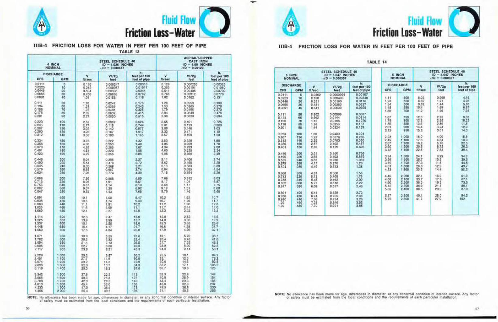
Fluid FlowFriction Loss -Water
Fluid FlowFriction Loss -Water
IIIB-4 FRICTION LOSS FOR WATER IN FEET PER 100 FEET OF PIPETABLE 13
IIIB·4 FRICTION LOSS FOR WATER IN FEET PER 100 FEET OF PIPE
ASPHALT·DIPPEDSTEEL SCHEDULE 40 CAST IRON
4 INCH 10 セ 4.026 INCHES 10 = 4.00 INCHESNOMINAL dO セ 0.000447 dO セ 0.00120
DISCHARGE h, h,V V2/2g feet per 100 V V2/2g feet per 100
CFS GPM ft/sec feet feet of pipe ft/sec feet feet of pipe
0.0111 5 0.126 0.000247 0.00310 0.128 0.000253 0.003250.0223 10 0.252 0.000987 0.01017 0.255 0.00101 0.010800.0446 20 0.504 0.00395 0.0344 0.511 0.00405 0.037000.0668 30 0.756 0.00888 0.0702 0.766 0.00912 0.07700.0981 40 1.01 0.0158 0.118 1.02 0.0162 0.131
0.111 50 1.26 0.0247 0.176 1.28 0.0253 0.1990.134 60 1.51 0.0355 0.245 1.53 0.0365 0.2780.156 70 1.76 0.0484 0.325 1.79 0.0496 0.3700.178 80 2.02 0.0632 0.415 2.04 0.0648 0.4760.201 90 2.27 0.0800 0.515 2.30 0.0820 0.594
0.223 100 2.52 0.0987 0.624 2.55 0.101 0.7250.245 110 2.77 0.119 0.744 2.81 0.123 0.8690.267 120 3.02 0.142 0.877 3.06 0.146 1.030.290 130 3.28 0.167 1.017 3.32 0.171 1.190.312 140 3.53 0.193 1.165 3.57 0.199 1.38
0.334 150 3.78 0.222 1.32 3.83 0.228 1.580.356 160 4.03 0.253 1.49 4.08 0.259 1.780.379 170 4.28 0.285 1.67 4.34 0.293 2.000.401 180 4.54 0.320 1.86 4.60 0.328 2.240.423 190 4.79 0.356 2.06 4.85 0.366 2.49
0.446 200 5.04 0.395 2.27 5.11 0.406 2.740.490 220 5.54 0.478 2.72 5.62 0.490 3.280.535 240 6.05 0.569 3.21 6.13 0.583 3.880.579 260 6.55 0.667 3.74 6.64 0.685 4.540.624 280 7.06 0.774 4.30 7.15 0.794 5.25
0.668 300 7.56 0.888 4.89 7.66 0.912 6.030.713 320 8.06 1.01 5.51 8.17 1.04 6.870.758 340 8.57 1.14 6.19 8.68 1.17 7.750.802 360 9.07 1.28 6.92 9.19 1.31 8.680.847 380 9.58 1.43 7.68 9.70 1.46 9.66
0.891 400 10.1 1.58 8.47 10.2 1.62 10.70.936 420 10.6 1.74 9.30 10.7 1.79 11.70.980 440 11.1 1.91 10.2 11.2 1.96 12.81.025 460 11.6 2.09 11.1 11.7 2.14 14.01.069 480 12.1 2.27 12.0 12.3 2.33 15.3
1.114 500 12.6 2.47 13.0 12.8 2.53 16.61.225 550 13.9 2.99 15.7 14.0 3.06 19.91.337 600 15.1 3.55 18.6 15.3 3.65 23.61.448 650 16.4 4.17 21.7 16.6 4.28 27.71.560 700 17.6 4.84 25.0 17.9 4.96 32.1
1.671 750 18.9 5.55 28.6 19.1 5.70 36.71.782 800 20.2 6.32 32.4 20.4 6.48 41.61.894 850 21.4 7.13 36.5 21.7 7.32 46.82.005 900 22.7 8.00 40.8 23.0 8.20 52.32.117 950 23.9 8.91 45.3 24.3 9.14 58.1
2.228 1000 25.2 9.87 50.2 25.5 10.1 64.22.451 1 100 27.7 11.9 60.5 28.1 12.3 78.22.674 1200 30.2 14.2 72.0 30.6 14.6 92.82.896 1300 32.8 16.7 84.3 33.2 17.1 108.23.119 1400 35.3 19.3 97.6 35.7 19.9 126
3.342 1500 37.8 22.2 112 38.3 22.8 1443.565 1600 40.3 25.3 127 40.8 25.9 1643.788 1700 42.8 28.5 143 43.4 29.3 1854.010 1800 45.4 32.0 160 46.0 32.8 2074.233 1900 47.9 35.6 178 48.5 36.6 2304.456 2000 50.4 39.5 196 51.1 40.5 255
NOTE: No allowance has been made for age, differences in diameter, or any abnormal condition of mtenor surface. Any factorof safety must be estimated from the local conditions and the requirements of each particular Installation.
56
•
TABLE 14
STEEL SCHEDULE 40 STEEL SCHEDULE 405 INCH 10 セ 5.047 INCHES 5 INCH 10 セ 5.047 INCHES
NOMINAL dO セ 0.000357 NOMINAL dO = 0.000357
DISCHARGE h, DISCHARGE h,V V2/2g feet per 100 V V212g feet per 100
CFS GPM ft/sec feet feet of pipe CFS GPM It/sec feet feet of pipe
0.0111 5 0.0802 0.0000999 0.001070.0223 10 0.160 0.000400 0.00348 1.11 500 8.02 0.999 4.160.0446 20 0.321 0.00160 0.0116 1.23 550 8.82 1.21 4.980.0668 30 0.481 0.00360 0.0237 1.34 600 9.62 1.44 5.880.0891 40 0.641 0.00639 0.0395 1.45 650 10.4 1.69 6.87
1.56 700 11.2 1.96 7.930.111 50 0.802 0.00999 0.05870.134 60 0.962 0.0144 0.0814 1.67 750 12.0 2.25 9.050.156 70 1.12 0.0196 0.1076 1.78 800 12.8 2.56 10.220.178 80 1.28 0.0256 0.137 1.89 850 13.6 2.89 11.50.201 90 1.44 0.0324 0.169 2.01 900 14.4 3.24 12.9
2.12 950 15.2 3.61 14.30.223 100 1.60 0.0400 0.2040.267 120 1.92 0.0576 0.286 2.23 1000 16.0 4.00 15.80.312 140 2.25 0.0783 0.380 2.45 1 100 17.6 4.84 19.00.356 160 2.57 0.102 0.487 2.67 1200 19.2 5.76 22.50.401 180 2.89 0.129 0.606 2.90 1300 20.8 6.75 26.3
3.12 1400 22.5 7.83 30.40.446 200 3.21 0.160 0.7360.490 220 3.53 0.193 0.879 3.34 1500 24.1 8.99 34.80.535 240 3.85 0.230 1.035 3.56 1600 25.7 10.2 39.50.579 260 4.17 0.270 1.20 3.79 1 700 27.3 11.6 44.50.624 280 4.49 0.313 1.38 4.01 1800 28.8 12.9 49.7
4.23 1900 30.5 14.4 55.20.668 300 4.81 0.360 1.580.713 320 5.13 0.409 1.78 4.46 2000 32.1 16.0 61.00.758 340 5.45 0.462 2.00 4.68 2100 33.7 17.6 67.10.802 360 5.77 0.518 2.22 4.90 2200 35.3 19.3 73.50.847 380 6.09 0.577 2.46 5.12 2300 36.9 21.1 80.1
5.35 2400 38.5 23.0 87.00.891 400 6.41 0.639 2.720.936 420 6.74 0.705 2.98 5.57 2500 40.1 25.0 94.20.980 440 7.06 0.774 3.26 5.79 2600 41.7 27.0 1021.02 460 7.38 0.846 3.551.07 480 7.70 0.921 3.85
NOTE: No allowance has been made for age, differences in diameter, or any abnormal condition of interior surface. Any factorat safety must be estimated from the local conditions and the requirements of each particular installation.
57

Fluid FlowFriction Loss -Water
IIIB.4 FRICTION LOSS FOR WATER IN FEET PER 100 FEET OF PIPETABLE 16
Fluid FlowFriction Loss-Water
IIIB-4 FRICTION LOSS FOR WATER IN FEET PER 100 FEET OF PIPE
TABLE 15
ASPHALT-DIPPEDSTEEL SCHEDULE 40 CAST IRON
6 INCH 10 = 6.065 INCHES 10 = 6.00 INCHESNOMINAL dO セ P N P P P R Y S ,/0 セ 0.000800
DISCHARGE h, h,V V2/2g feet per 100 V V2/2g feet per 100
CFS GPM ft/sec feet feet of pipe ft/sec feet feet of pipe
0.0223 10 0.111 0.000192 0.00146 0.113 0.000200 0.001570.0446 20 0.222 0.000767 0.00487 0.227 0.000800 0.005230.0668 30 0.333 0.00172 0.00988 0.340 0.00180 0.010700.0891 40 0.444 0.00307 0.0164 0.454 0.00320 0.01790.111 50 0.555 0.00479 0.0244 0.567 0.00500 0.02680.134 60 0.666 0.00690 0.0337 0.681 0.00720 0.03740.156 70 0.777 0.00939 0.0445 0.794 0.00960 0.04960.178 80 0.888 0.0123 0.0564 0.908 0.0126 0.06350.201 90 0.999 0.0155 0.0698 1.02 0.0162 0.07890.223 100 1.11 0.0192 0.0843 1.13 0.0200 0.09580.267 120 1.33 0.0276 0.118 1.36 0.0288 0.1300.312 140 1.55 0.0376 0.155 1.59 0.0392 0.1780.356 160 1.78 0.0491 0.198 1.82 0.0512 0.2290.401 180 2.00 0.0621 0.246 2.04 0.0648 0.2820.446 200 2.22 0.0767 0.299 2.27 0.0800 0.3460.490 220 2.44 0.0927 0.357 2.50 0.0968 0.4150.535 240 2.66 0.110 0.419 2.72 0.115 0.4900.579 260 2.89 0.130 0.487 2.95 0.135 0.5700.624 280 3.11 0.150 0.560 3.18 0.157 0.6550.668 300 3.33 0.172 0.637 3.40 0.180 0.7450.713 320 3.55 0.196 0.719 3.63 0.205 0.8460.758 340 3.78 0.222 0.806 3.86 0.231 0.9520.802 360 4.00 0.240 0.898 4.08 0.259 1.060.847 380 4.22 0.277 0.993 4.31 0.289 1.180.891 400 4.44 0.307 1.09 4.54 0.320 1.300.936 420 4.66 0.338 1.20 4.76 0.353 1.430.980 440 4.89 0.371 1.31 4.99 0.387 1.571.025 460 5.11 0.405 1.42 5.22 0.423 1.711.07 480 5.33 0.442 1.54 5.45 0.461 1.861.11 500 5.55 0.479 1.66 5.67 0.500 2.021.23 550 6.11 0.580 1.99 6.24 0.605 2.421.34 600 6.66 0.690 2.34 6.81 0.720 2.841.45 650 7.22 0.810 2.73 7.37 0.845 3.331.56 700 7.77 0.939 3.13 7.94 0.980 3.871.67 750 8.33 1.08 3.57 8.51 1.12 4.451.78 800 8.88 1.23 4.03 9.08 1.28 5.061.89 850 9.44 1.38 4.53 9.64 1.44 5.692.01 900 9.99 1.55 5.05 10.2 1.62 6.342.12 950 10.5 1.73 5.60 10.8 1.80 7.022.23 1000 11.1 1.92 6.17 11.3 2.00 7.732.45 1 100 12.2 2.32 7.41 12.5 2.42 9.802.67 1200 13.3 2.76 8.76 13.6 2.88 11.22.90 1300 14.4 3.24 10.2 14.7 3.38 13.03.12 1400 15.5 3.76 11.6 15.9 3.92 15.13.34 1500 16.7 4.31 13.5 17.0 4.50 17.43.56 1600 17.8 4.91 15.4 18.2 5.12 19.83.79 1700 18.9 5.54 17.3 19.3 5.78 22.34.01 1800 20.0 6.21 19.4 20.4 6.48 24.84.23 1900 21.1 6.92 21.6 21.6 7.22 27.64.46 2000 22.2 7.67 23.8 22.7 8.00 30.54.68 2100 23.3 8.45 26.2 23.8 8.82 33.64.90 2200 24.4 9.27 28.8 25.0 9.68 36.85.12 2300 25.5 10.1 31.4 26.1 10.6 40.15.35 2400 26.6 11.0 34.2 27.2 11.5 43.55.57 2500 27.8 12.0 37.0 28.4 12.5 47.15.79 2600 28.9 13.0 39.9 29.5 13.5 51.06.02 2700 30.0 14.0 42.9 30.6 14.6 55.26.24 2800 31.1 15.0 46.1 31.8 15.7 59.66.46 2900 32.2 16.1 49.4 32.9 16.6 64.16.68 3000 33.3 17.2 52.8 34.0 18.0 68.87.13 3200 35.5 19.6 59.9 36.3 20.5 78.07.58 3400 37.8 22.2 67.4 38.6 23.1 88.08.02 3600 40.0 24.8 75.5 40.8 25.9 98.78.47 3800 42.2 27.7 84.1 43.1 28.9 1108.91 4000 44.4 30.7 93.1 45.4 32.0 122
ASPHALT-DIPPEDSTEEL SCHEDULE 40 CAST IRON
8 INCH 10 セ 7.981 INCHES 10 セ 8.00 INCHES
NOMINAL dO = 0.000226 ,/0 セ 0.00060
h, h,DISCHARGE V V2/2g feet per 100 V V2/2g feet per 100
CFS GPM ft/sec feet feet of pipe ft/sec feet feet of pipe
0.0223 10 0.0641 0.0000639 0.000401 0.0638 0.0000633 0.000399
20 0.128 0.000256 0.001320 0.128 0.000253 0.0013200.0446 0.000570 0.00269
30 0.192 0.000575 0.00266 0.1910.0668 0.00101 0.00447
40 0.257 0.00102 0.00442 0.2550.0891 0.00158 0.006640.111 50 0.321 0.00160 0.00652 0.319
60 0.385 0.00230 0.00904 0.382 0.00228 0.009200.134 0.00310 0.012100.156 70 0.449 0.00313 0.01190 0.447
80 0.513 0.00409 0.0151 0.511 0.00405 0.01540.178 0.574 0.00513 0.0191
90 0.577 0.00516 0.01860.201 0.638 0.00633 0.02320.223 100 0.641 0.00639 0.0224
0.770 0.00920 0.0311 0.766 0.00911 0.03230.267 120 0.893 0.0124 0.04280.312 140 0.898 0.0125 0.0410
0.0162 0.05480.356 160 1.03 0.0164 0.0521 1.02
0.0205 0.06810.401 180 1.15 0.0207 0.0644 1.15
1.28 0.0253 0.08280.446 200 1.28 0.0256 0.0780
0.490 220 1.41 0.0309 0.0928 1.40 0.0306 0.0989
240 1.54 0.0368 0.1088 1.53 0.0365 0.11630.535 0.0428 0.135
260 1.67 0.0432 0.1260 1.660.579 1.79 0.0496 0.1550.624 280 1.80 0.0501 0.144
0.163 1.91 0.0570 0.1760.668 300 1.92 0.0575
320 2.05 0.0655 0.184 2.04 0.0648 0.1980.713 0.206 2.17 0.0732 0.2220.758 340 2.18 0.0739
0.229 2.30 0.0820 0.2480.602 360 2.31 0.0828
380 2.44 0.0923 0.253 2.43 0.0914 0.2750.847 0.101 0.3040.891 400 2.57 0.102 0.279 2.55
2.89 0.129 0.346 2.87 0.128 0.3801.003 450 0.158 0.464
500 3.21 0.160 0.424 3.191.11 0.507 3.51 0.191 0.5571.23 550 3.53 0.193
3.83 0.228 0.6581.34 600 3.85 0.230 0.597
0.267 0.7671.45 650 4.17 0.271 0.694 4.15
700 4.49 0.313 0.797 4.47 0.310 0.8841.56 0.356 1.011.67 750 4.81 0.360 0.907 4.79
0.405 1.141.78 800 5.13 0.409 1.02 5.11
1.147 5.42 0.457 1.291.89 850 5.45 0.462
0.513 1.442.01 900 5.77 0.518 1.27 5.74
6.09 0.577 1.41 6.06 0.571 1.602.12 950 0.633 1.762.23 1000 6.41 0.639 1.56 6.38
7.05 0.773 1.87 7.02 0.766 2.142.45 1100
2.20 7.66 0.911 2.532.67 1200 7.70 0.920
8.30 1.07 2.942.90 1300 8.34 1.08 2.56
8.98 1.25 2.95 8.93 1.24 3.403.12 1400
3.37 9.57 1.42 3.913.34 1500 9.62 1.44
1.62 4.453.56 1600 10.3 1.64 3.82 10.2
10.9 1.65 4.29 10.8 1.83 5.003.79 1700 2.05 5.584.01 1600 11.5 2.07 4.79 11.5
12.2 2.31 5.31 12.1 2.29 6.194.23 1900
5.86 12.8 2.53 6.844.46 2000 12.8 2.56
7.02 14.0 3.06 8.264.90 2200 14.1 3.09
3.65 9.805.35 2400 15.4 3.68 8.31 15.3
4.28 11.475.79 2600 16.7 4.32 9.70 16.6
18.0 5.01 11.20 17.9 4.96 13.36.24 2600 5.70 15.26.68 3000 19.2 5.75 12.8 19.1
6.48 17.37.13 3200 20.5 6.55 14.5 20.4
7.32 19.57.58 3400 21.8 7.39 16.4 21.7
18.4 23.0 8.20 21.96.02 3600 23.1 8.28
24.4 9.23 20.5 24.3 9.14 24.48.47 3800
22.6 25.5 10.1 27.08.91 4000 25.7 10.2
28.7 12.8 34.010.03 4500 28.9 12.9 28.5
32.1 16.0 35.1 31.9 15.8 42.011.1 5000
42.5 35.1 19.1 51.012.3 5500 35.3 19.3
38.5 23.0 50.5 38.3 22.8 80.513.4 6000 26.7 71.0
41.7 27.0 59.1 41.514.5 6500 31.0 82.015.6 7000 44.9 31.3 68.3 44.7
78.1 47.9 35.6 94.016.7 7500 48.1 36.0
88.6 51.1 40.5 10717.8 6000 51.3 40.9
56 59

STEEL SCHEDULE 40ASPHALT-DIPPED
10 INCHCAST IRON
NOMINAL10 セ 10.020 INCHES 10 = 10.00 INCHES
etO - 0.000180 dO 0.000480
DISCHARGEV I
h, h,
CFS IV2/2g feel per 100 V V2/2g feet per 100
GPM U/sec feet feet of pipe ft/sec feet feet of pipe
0.0223 10 0.0407 0.0000257 0.000138 I 0.0409 0.00002590.0446
0.00014020 0.0814 0.000103 0.000451 0.0817 0.000104
0.0891 40 0.1630.000460
0.000412 0.00149 0.163 0.000415 0.001540.134 60 0.244 0.000926 0.00304 0.245 0.000934 0.003150.178 80 0.325 0.00165 0.00505 0.327 0.00166 0.005250.223 100 0.407 0.00257 0.00747 0.409 0.002590.267
0.00783120 0.488 0.00370 0.0103 0.490 0.00373 0.Q1085
0.312 140 0.570 0.00504 0.0136 0.572 0.00508 0.01440.356 160 0.651 0.00659 0.0174 0.654 0.006640.401
0.0183180 0.732 0.00834 0.0215 0.735 0.00640 0.0227
0.446 200 0.814 0.0103 0.0260 0.817 0.0104 0.02760.490 220 0.895 0.0125 0,0309 0,899 0.01260.535
0.0329240 0.976 0.0148 0.0362 0.960 0.0149
0.579 2600.0367
1.06 0.0174 0.0417 1.06 0,0175 0.04490.624 260 1.14 0.0202 0,0478 1,14 0,0203 0.05140.668 300 1.22 0,0232 0.0542 1.23 0,0233 0,05630.780 350 1.42 0.0315 0.0719 1.43 0.0318 0,07780.891 400 1.63 0,0412 0.0917 1.63 0.0415 0,09901.003 450 1.83 0,0521 0.114 1.84 0.05251.11 500
0,12352.03 0,0643 0.138 2,04 0,0648 0.151
I1.23 550 2.24 0.0778 0.164 2,25 0,07851.34 600
0.1812.44 0,0926 0,192 2.45 0.0934 0,214
1.45 650 2.64 0.109 0.224 2.66 0.110 0.2501.56 700 2.85 0.126 0.256 2.86 0.1271.67 750 3.05
0,2880.145 0.291 3.06 0.146 0.328
1.78 800 3.25 0.165 0.328 3.27 0.1661.89 850 3.46 0.186 0.368
0.3703.47 0.187 0.415
2.01 900 3.66 0.208 0.410 3.68 0.2102.12
0.462950 3.87 0.232 0.455 3.88 0.234 0.512
2.23 1000 4.07 0.257 0.500 4.09 0.259 0.5652.45 1 100 4,48 0.311 0,600 4.49 0.3142.67 1200 4.88
0.6800.370 0.703 4.90 0.373 0.805
2.90 1300 5,29 0.435 0.818 5,31 0.438 0.9453.12 1400 5,70 0.504 0.940 5.72 0.508 1.093.34 1500 6.10 0,579 1.07 6.13 0.584 1.253.56 1600 6,51 0.659 1.21 6.54 0.664 1.423.79 1700 6.92 0.743 1,36 6.94 0.7494.01 1800 7.32 0,834 1,52 7.35
1.600,840 1.78
4,23 1900 7.73 0.929 1.68 7.76 0.936 1.974.46 2000 8.14 1,03 1,86 8,17 1,04 2.174,90 2200 8,95 1.25 2,23 8,99 1,265,35 2400 9.76 1.48 2,64 9,80
2.641.49 3.12
5,79 2600 10,6 1.74 3.08 10.66.24 2800
1.75 3.6311.4 2,02 3.56 11.4 2.03
6.684.18
3000 12.2 2,32 4,06 12.3 2.33 4.797.13 3200 13.0 2.63 4.59 13.1 2.667.58 3400 13.8 2.97 5.16 13.9
5.47
8.02 36003.00 6.18
14.6 3.33 5.76 14.7 3.368.47 3800
6.9115.5 3.71 6.40 15.5 3.74
8.917.68
4000 16.3 4.12 7.07 16.3 4.15 8.5010.03 4500 18.3 5.21 8.88 18.4 5.2511.1 5000 20.3
10.7
12.3 55006.43 10.9 20.4 6.48 13.2
22.4 7.78 13.2 22.5 7.8513.4 6000
15.924.4 9.26 15.6 24.5 9.34 18.9
14.5 6500 26.4 10.9 18.3 26.6 11.0 22.215.6 7000 28.5 12.6 21.1 28.6 12.716.7 7500
25.830.5 14.5 24.3 30.0 14.6 29.6
17.8 8000 32,5 16.5 27,5 32.7 16.618.9
33.68500 34.6 18.6 30.9 34.7 18.7
20,1 900037.8
36,6 20.8 34,6 36.8 21.0 42.221.2 9500 38,7 23,2 38,5 38.8 23.422.3 10000
46.940.7 25,7 42,6 40,9 25.9 51.8
61
Friction Loss-WaterIllB-4 FRICTION LOSS FOR WATER IN FEET PER 100 FEET OF PIPE
TABLE 18ASPHALT-DIPPED
STEEL SCHEDULE 40 CAST IRON
12 INCH 10 = 11.938 INCHES 10 セ 12.00 INCHES
NOMINAL flO = 0.000151 flO = 0.000400
DISCHARGEh, h,
V V2/2g feet per 100 V V2/2g feet per 100
CFS GPM ft/sec feet feet of pipe It/sec feet feet of pipe
0,223 100 0.287 0,00128
I0,00325
I0.284 0.00125 0.00320
0.267 120 0.344 0.00184 0,00448 0,340 0.00180 0.00445
0,312 140 0.401 0.00250 0.00590 0.397 0.00245 0.00589
0.356 160 0.459 0,00327 0.00747 0.454 0,00320 0.00752
0.401 180 0.516 0.00414 0.00920 0.511 0.00405 0,00932
0.446 200 0.573 0.00511 0.0111 0.567 0.00500 0.01129
0.490 220 0.631 0.00618 0.0132 0.624 0,00605 0.0135
0.535 240 0.688 0.00735 0.0155 0.681 0.00720 0.0158
0.579 260 0.745 0.00863 0.0180 0,738 0.00845 0.0182
0,624 280 0.802 0.0100 0.0206 0.794 0.00980 0,0208
0.668 300 0.860 0.0115 0.0233 0,851 0.0113 0.0236
0.780 350 1.00 0.0156 0.0306 0.993 0.0153 0.0316
0.891 400 1.15 0.0204 0,0391 1.13 0.0200 0.0404
1.00 450 1.29 0.0259 0.0485 1.28 0.0253 0.0500
1.11 500 1.43 0.0319 0.0587 1.42 0.0313 0.0604
1.23 550 1.58 0,0386 0.0698 1,56 0.0378 0.0718
1,34 600 1.72 0.0460 0.0820 1.70 0.0450 0,0845
1.45 650 1,86 0.0539 0.0950 1.84 0.0528 0,0990
1.56 700 2.01 0,0626 0,109 1,99 0.0613 0.115
1.67 750 2,15 0.0716 0.124 2,13 0,0703 0.131
1.78 800 2.29 0,0617 0.140 2,27 0,0800 0.148
1,89 850 2.44 0,0922 0.156 2.41 0.0903 0.166
2.01 900 2.58 0,103 0,173 2,55 0.101 0.184
2.12 950 2.72 0,115 0.191 2.69 0,113 0,203
2.23 1000 2.87 0,128 0,210 2.84 0.125 0.224
2.45 1100 3.15 0.154 0,251 3.12 0.151 0.272
2.67 1200 3.44 0.184 0.296 3.40 0.180 0,321
2.90 1300 3.73 0.216 0.344 3.69 0.211 0.372
3.12 1400 4.01 0.250 0.395 3.97 0.245 0.428
3.34 1500 4.30 0.287 0.450 4.26 0.281 0.488
3.56 1600 4,59 0.327 0.509 4.54 0.320 0.552
3.79 1700 4,87 0.369 0.572 4,82 0.361 0.621
4.01 1600 5.16 0.414 0.636 5.11 0.405 0,695
4.23 1900 5.45 0.461 0.704 5.39 0.451 0.774
4.46 2000 5.73 0.511 0.776 5.67 0.500 0.858
4,90 2200 6.31 0.618 0.930 6.24 0.605 1.03
5.35 2400 6.88 0.735 1.093 6.81 0.720 1.22
5.79 2600 7.45 0.863 1.28 7.38 0,845 1.43
6.24 2800 8.03 1.00 1.47 7.94 0.980 1.65
6.68 3000 8.60 1.15 1.68 8,51 1.13 1.88
7,13 3200 9.17 1.31 1.90 9,08 1.28 2.13
7.58 3400 9.75 1.48 2.13 9,65 1.45 2.41
8,02 3600 10.3 1,65 2,37 10.2 1.62 2,70
8.47 3800 10,9 1.84 2.63 10.8 1.81 3.00
8.91 4000 11.5 2.04 2,92 11.3 2.00 3.31
10,03 4500 12,9 2.59 3.65 12.8 2.53 4.18
11.1 5000 14.3 3.19 4.47 14.2 3.13 5.13
12.3 5500 15,8 3.86 5.38 15.6 3.78 6.17
13.4 6000 17.2 4.60 6.39 17.0 4.50 7.30
14.5 6500 18.6 5.39 7.47 18.4 5.28 8.55
15.6 7000 20.1 6.26 8.63 19.9 6.13 9.92
16.7 7500 21.5 7.18 9.88 21.3 7.03 11.4
17.8 8000 22.9 8.17 11.20 22.7 8,00 13.0
18,9 8500 24,4 9.22 12.6 24.1 9.04 14.7
20.1 9000 25.8 10.3 14.1 25.5 10.1 16.4
21.2 9500 27.2 11.5 15.7 26.9 11.3 18.2
22.3 10000 28.7 12.8 17.4 28.4 12,5 20.2
24.5 11 000 31.5 15.4 21.0 31.2 15.1 24.2
26.7 12000 34.4 18.3 24.8 34.0 18.0 28.8
29.0 13000 37,3 21.6 28.9 36.9 21.1 34.0
31.2 14 000 40.1 25,0 33,5 39.7 24.5 39.7
33.4 15000 43,0 28.7 38.4 42.6 28,1 45.7
35.6 16000 45,9 32.7 43.7 45.4 32.0 51,g
37.9 17000 48,7 36.9 49.2 48.2 36,1 58.2
40.1 18000 51,6 41.4 55,2 51,1 40,5 65.0
42.3 19000 54.5 46.1 61,5 53.9 45,1 72.1
44.6 20000 57.3 51,1 68.1 56.7 50.0 79.8
Iuid FlowFriction Loss- Water
Nセ
IllB-4 FRICTION LOSS FOR WATER IN FEET PER 100 FEET OF PIPE
TABLE 17
60

..Fluid Flow
Friction Loss-WaterillS-4 FRICTION LOSS FOR WATER IN FEET PER 100 FEET OF PIPE
Fluid FlowFriction Loss- Water
illS-4 FRICTION LOSS FOR WATER IN FEET PER 100 FEET OF PIPE
TABLE 19
ASPHALT-DIPPEDSTEEL- SCHEDULE 40 CAST IRON14 INCH 00 10 セ 13.124 INCHES 10 = 14.00 INCHESdD = 0.000137 £10 = 0.000343DISCHARGE h, h,V V2/2g feet per 100 V V2/2g feet per 100CFS GPM ft/sec feet feet of pipe ft/sec feet feet of pipe0.446 200 0.474 0.00349 0.00704 0.417 0.00270 0.005330.557 250 0.593 0.00546 0.Q105 0.521 0.00422 0.008000.668 300 0.711 0.00786 0.0147 0.625 0.00608 0.01120.780 350 0.830 0.0107 0.0194 0.729 0.00827 0.01480.891 400 0.948 0.0140 0.0247 0.834 0.0108 0.0190
1.114 500 1.19 0.0218 0.0370 1.04 0.0169 0.02841.34 600 1.42 0.0314 0.0517 1.25 0.0243 0.04001.56 700 1.66 0.0428 0.0683 1.46 0.0330 0.05331.78 800 1.90 0.0559 0.0872 1.67 0.0432 0.06862.01 900 2.13 0.0708 0.108 1.88 0.0547 0.08592.23 1000 2.37 0.0874 0.131 2.08 0.0675 0.10502.45 1100 2.61 0.106 0.157 2.29 0.0817 0.12562.67 1200 2.85 0.126 0.185 2.50 0.0972 0.1482.90 1300 3.08 0.148 0.215 2.71 0.114 0.1723.12 1400 3.32 0.171 0.247 2.92 0.132 0.1983.34 1500 3.56 0.197 0.281 3.13 0.152 0.2253.56 1600 3.79 0.224 0.317 3.33 0.173 0.2543.79 1700 4.03 0.252 0.355 3.54 0.195 0.2854.01 1800 4.27 0.283 0.395 3.75 0.219 0.3184.23 1900 4.50 0.315 0.438 3.96 0.244 0.3534.46 2000 4.74 0.349 0.483 4.17 0.270 0.3905.57 2500 5.93 0.546 0.738 5.21 0.422 0.6006.68 3000 7.11 0.786 1.04 6.25 0.608 0.8557.80 3500 8.30 1.07 1.40 7.29 0.827 1.168.91 4000 9.48 1.40 1.81 8.34 1.08 1.5010.02 4500 10.7 1.77 2.27 9.38 1.37 1.8811.1 5000 11.9 2.18 2.78 10.4 1.69 2.3013.4 6000 14.2 3.14 3.95 12.5 2.43 3.3115.6 7000 16.6 4.28 5.32 14.6 3.30 4.5017.8 8000 19.0 5.59 6.90 16.7 4.32 5.8720.1 9000 21.3 7.08 8.7 18.8 5.47 7.4222.3 10000 23.7 8.74 10.7 20.8 6.75 9.1524.5 11 000 26.1 10.6 12.9 22.9 8.17 11.0526.7 12000 28.5 12.6 15.2 25.0 9.72 13.029.0 13000 30.8 14.8 17.8 27.1 11.4 15.2
31.2 14000 33.2 17.1 20.7 29.2 13.2 17.633.4 15000 35.6 19.7 23.7 31.3 15.2 20.235.6 16000 37.9 22.4 26.8 33.3 17.3 23.037.9 17 000 40.3 25.2 30.2 35.4 19.5 26.040.1 18000 42.7 28.3 33.9 37.5 21.9 29.242.3 19000 45.0 31.5 37.8 39.6 24.4 32.644.6 20000 47.4 34.9 41.9 41.7 27.0 36.249.0 22000 52.2 42.3 50.6 45.9 32.7 43.553.5 24000 56.9 50.3 60.0 50.0 38.9 51.957.9 26000 61.6 59.1 70.3 54.2 45.6 61.262.4 28000 66.4 68.5 81.4 58.4 52.9 71.266.8 30000 71.1 78.6 93.4 62.5 60.8 81.6
TABLE 20
ASPHALT-DIPPEDSTEEL- SCHEDULE 40 CAST IRON
16 INCH 00 10 セ 15.000 INCHES 10 = 16.00 INCHES./0 0.000120 tiD = 0.000300
h, h,DISCHARGEV V2/2g feet per 100 V V2/2g feet per 100
CFS GPM ft/sec feet feet of pipe ft/sec leet feet of pipe
0.545 0.00461 0.00769 0.479 0.00356 0.005810.668 3000.0129 0.638 0.00633 0.009800.891 400 0.726 0.00820
0.00989 0.01481.114 500 0.908 0.0128 0.0193 0.7981.09 0.0184 0.0269 0.957 0.0142 0.02071.34 600
0.0194 0.02761.56 700 1.27 0.0251 0.0356 1.12
1.45 0.0328 0.0454 1.28 0.0253 0.03541.78 8001.44 0.0320 0.04412.01 900 1.63 0.0415 0.0563
1000 1.82 0.0512 0.0683 1.60 0.0396 0.05372.230.0953 1.91 0.0570 0.07602.67 1200 2.18 0.0738
0.1013.12 1400 2.54 0.1004 0.127 2.23 0.0775
1600 2.90 0.131 0.163 2.55 0.101 0.1303.560.203 2.87 0.128 0.1634.01 1800 3.27 0.1660.248 3.19 0.158 0.2004.46 2000 3.63 0.2050.377 3.99 0.247 0.3075.57 2500 4.54 0.3200.535 4.79 0.356 0.4356.68 3000 5.45 0.461
3500 6.35 0.627 0.718 5.58 0.485 0.5847.800.921 6.38 0.633 0.7548.91 4000 7.26 0.8201.15 7.18 0.801 0.94810.02 4500 8.17 1.04
7.98 0.989 1.175000 9.08 1.28 1.4111.19.57 1.42 1.6613.4 6000 10.9 1.84 2.01
12.7 2.51 2.69 11.2 1.94 2.2615.6 70002.968000 14.5 3.28 3.49 12.8 2.5317.8
4.38 14.4 3.20 3.7320.1 9000 16.3 4.153.96 4.5710000 18.2 5.12 5.38 16.022.3
6.49 17.6 4.79 5.5024.5 11 000 20.0 6.20
12000 21.8 7.38 7.69 19.1 5.70 6.5226.78.99 20.7 6.69 7.6329.0 13000 23.6 8.66
22.3 7.75 8.8131.2 14000 25.4 10.04 10.411.5 11.9 23.9 8.90 10.133.4 15000 27.2
25.5 10.1 11.535.6 16000 29.0 13.1 13.5
17000 30.9 14.8 15.3 27.1 11.4 13.037.912.8 14.640.1 18000 32.7 16.6 17.2 28.714.3 16.342.3 19000 34.5 18.5 19.2 30.315.8 18.144.6 20000 36.3 20.5 21.2 31.9
25.5 35.1 19.1 21.849.0 22000 39.9 24.8
24000 43.6 29.5 30.2 38.3 22.8 25.953.535.4 41.5 26.7 30.457.9 26000 47.2 34.6
31.0 35.362.4 28000 50.8 40.2 41.0 44.747.0 47.9 35.6 40.566.8 30000 54.5 46.1
40.5 46.071.3 32000 58.1 52.4 53.5 51.1
34000 61.7 59.2 60.2 54.3 45.7 51.975.851.3 58.180.2 36000 65.4 66.4 67.2 57.4
38000 69.0 74.0 75.0 60.6 57.1 64.784.783.0 63.8 63.3 71.789.1 40000 72.6 82.0
69.8 79.193.6 42000 76.2 90.4 91.5 67.0
44000 79.9 99.2 101 70.2 76.6 86.998.0110 73.4 83.7 95.0102.5 46000 83.5 108.4
91.2 10348000 87.1 118 118 76.610798.9 112111 50000 90.8 128 128 79.8
NOTE: No allowance has been made for age, differences in diameter, or any abnormal condition of interior surface. Any factorof safety must be estimated from the tocal conditions and the requirements of each particular Installation. h b n made for a e differences in diameter or any abnormal condition of interior surface. Any factor
NOTE: セ ヲ o ウ セ セ セ エ セ 。 セ セ セ エ セ Z ・ [ セ ュ 。 エ ・ 、 from tfie I local conditions and エ ィ セ requirements of each particular installation.
62
63

Fluid FlowFriction Loss- Water
IIIB·4 FRICTION lOSS FOR WATER IN FEET PER 100 FEET OF PIPE
Fluid FlowFriction Loss -Water
IIIB·4 FRICTION lOSS FOR WATER IN FEET PER 100 FEET OF PIPE
TABLE 21
ASPHALT-DIPPEDSTEEL- SCHEDULE 40 CAST IRON18 INCH 00 10 = 16.876 INCHES 10 セ 18.00 INCHESdO = 0.000107 dO = 0.000267
DISCHARGE h, h,V V2/2g feet per 100 V V2/2g feet per 100CFS GPM It/sec feet feet of plDe ft/sec feet feet of pipe0.668 300 0.430 0.00288 0.00437 0.378 0.00222 0.003280.891 400 0.574 0.00512 0.00730 0.504 0.00359 0.005541.114 500 0.717 0.00799 0.D109 0.630 0.00618 0.008321.34 600 0.861 0.0115 0.0152 0.756 0.00889 0.011621.56 700 1.00 0.0157 0.0201 0.883 0.0121 0.01541.78 800 1.15 0.0205 0.0256 1.01 0.0158 0.01972.01 900 1.29 0.0259 0.0318 1.13 0.0200 0.02452.23 1000 1.43 0.0320 0.0386 1.26 0.0247 0.02982.67 1200 1.72 0.0460 0.0541 1.51 0.0356 0.04203.12 1400 2.01 0.0627 0.0719 1.77 0.0484 0.05603.56 1600 2.30 0.0819 0.092 2.02 0.0632 0.07284.01 1800 2.58 0.1036 0.114 2.27 0.0800 0.09104.46 2000 2.87 0.128 0.139 2.52 0.0988 0.1105.57 2500 3.59 0.200 0.211 3.15 0.154 0.1706.68 3000 4.30 0.288 0.297 3.78 0.222 0.2407.80 3500 5.02 0.392 0.397 4.41 0.303 0.3208.91 4000 5.74 0.512 0.511 5.04 0.395 0.41510.02 4500 6.45 0.647 0.639 5.67 0.500 0.52511.1 5000 7.17 0.799 0.781 6.30 0.618 0.64513.4 6000 8.61 1.15 1.11 7.56 0.889 0.920
15.6 7000 10.0 1.57 1.49 8.83 1.21 1.2417.8 8000 11.5 2.05 1.93 10.09 1.58 1.6120.1 9000 12.9 2.59 2.42 11.3 2.00 2.0222.3 10 000 14.3 3.20 2.97 12.6 2.47 2.4826.7 12000 17.2 4.60 4.21 15.1 3.56 3.5631.2 14000 20.1 6.27 5.69 17.7 4.84 4.8535.6 16000 22.9 8.19 7.41 20.2 6.32 6.3440.1 18000 25.8 10.36 9.33 22.7 8.00 8.0244.6 20000 28.7 12.8 11.5 25.2 9.88 9.8849.0 22000 31.6 15.5 13.9 27.7 12.0 11.90
53.5 24000 34.4 18.4 16.5 30.3 14.2 14.1057.9 26000 37.3 21.6 19.2 32.8 16.7 16.5062.4 28000 40.2 25.1 22.2 35.3 19.4 19.166.8 30000 43.0 28.8 25.5 37.8 22.9 21.971.3 32000 45.9 32.7 29.0 40.3 25.3 24.975.8 34000 48.8 37.0 32.8 42.9 28.6 28.180.2 36000 51.6 41.4 36.8 45.4 32.0 31.584.7 38000 54.5 46.2 40.8 47.9 35.7 35.189.1 40000 57.4 51.2 45.0 50.4 39.5 38.993.6 42000 60.2 56.4 49.7 53.0 43.6 42.998 44000 63.1 61.9 54.5 55.5 47.8 47.0102 46000 66.0 67.7 59.5 58.0 52.3 51.3107 48000 68.9 73.7 64.8 60.5 56.9 55.8111 50000 71.7 79.9 70.2 63.0 61.8 60.5123 55000 78.9 96.7 84.8 69.3 74.7 73.0
134 60000 86.1 115 101 75.6 88.9 86.7145 65000 93.2 135 118 82.0 104.4 101.8156 70000 100.4 157 136 88.3 121 118
NOTE: No allowance has been made for age, differences in diameter, or any abnormal condition of interior surface. Any factorof safety must be estimated from the local conditions and the requirements of each particular installation.
TABLE 22
ASPHALT-DIPPEDSTEEL- SCHEDULE 40 CAST IRON
20 INCH 00 10 セ 18.812 INCHES 10 = 20.00 INCHESdO 0.0000957 dO = 0.000240
h, h,DISCHARGEV V2/2g feet per 100 V V2/2g feet per 100
CFS GPM ft/sec feet feet of pipe It/sec feet feet of pipe
0.346 0.00186 0.00258 0.306 0.00146 0.001970.668 3000.408 0.00259 0.003320.891 400 0.462 0.00331 0.00432
0.004960.00645 0.511 0.004051.114 500 0.577 0.005170.00583 0.006911.34 600 0.692 0.00745 0.00897 0.613
0.009161.56 700 0.808 0.0101 0.01186 0.715 0.00794
0.923 0.0132 0.0152 0.817 0.0104 0.01171.78 8000.919 0.0131 0.01460.0168 0.01882.01 900 1.0391.02 0.0162 0.01772.23 1000 1.15 0.0207 0.02271.23 0.0233 0.02492.67 1200 1.38 0.0298 0.0318
0.03323.12 1400 1.62 0.0406 0.0422 1.43 0.0318
1.85 0.0530 0.0538 1.63 0.0415 0.04273.56 16000.05332.08 0.0671 0.0669 1.84 0.05254.01 1800
0.0648 0.06500.0828 0.0812 2.044.46 2000 2.310.1013 0.09985.57 2500 2.89 0.129 0.123 2.55
0.174 3.06 0.146 0.1406.68 3000 3.46 0.186
4.04 0.254 0.232 3.57 0.198 0.1887.80 35000.298 4.08 0.259 0.2438.91 4000 4.62 0.331
5.19 0.419 0.372 4.59 0.328 0.30610.02 45000.37611.1 5000 5.77 0.517 0.455 5.11 0.405
6000 6.92 0.745 0.645 6.13 0.583 0.53313.4
8.08 1.014 0.862 7.15 0.794 0.72115.6 70001.32 1.11 8.17 1.04 0.93517.8 8000 9.23
9000 10.39 1.68 1.39 9.19 1.31 1.1820.11.70 10.2 1.62 1.4522.3 10 000 11.5 2.07
2.0726.7 12000 13.8 2.98 2.44 12.3 2.33
14000 16.2 4.06 3.29 14.3 3.18 2.8031.216.3 4.15 3.6616000 18.5 5.30 4.2635.6
5.35 18.4 5.25 4.6240.1 18000 20.8 6.715.678.28 6.56 20.4 6.4844.6 20000 23.1
22.5 7.84 6.8549.0 22000 25.4 10.02 7.91
24000 27.7 11.9 9.39 24.5 9.33 8.1353.526.5 10.95 9.5457.9 26000 30.0 14.0 11.0
28000 32.3 16.2 12.7 28.6 12.7 11.162.430000 34.6 18.6 14.6 30.6 14.6 12.766.8
16.6 14.471.3 32000 36.9 21.2 16.6 32.7
34000 39.2 23.9 18.7 34.7 18.7 16.375.836000 41.5 26.8 20.9 36.8 21.0 18.280.238000 43.9 29.9 23.2 38.8 23.4 20.284.7
25.7 40.8 25.9 22.489.1 40000 46.2 33.128.4 42.9 28.6 24.793.6 42000 48.5 36.5
44000 50.8 40.1 31.3 44.9 31.4 27.19846000 53.1 43.8 34.2 47.0 34.3 29.7102
49.0 37.3 32.448000 55.4 47.7 37.110751.1 40.5 35.2111 50000 57.7 51.7 40.056.2 49.0 42.4123 55000 63.5 62.6 48.3
60000 69.2 74.5 57.4 61.3 58.3 50.413465000 75.0 87.4 67.2 66.4 68.5 59.0145
77.8 71.5 79.4 68.4156 70000 80.8 101.478.6167 75000 86.6 116 89.3 76.6 91.1
80000 92.3 132 102 81.7 103.7 89.5178
85000 98.1 150 115 86.8 117 10118990000 103.9 168 129 91.9 131 113201
97.0 146 126212 95000 109.6 187 143139223 100000 115.4 207 158 102.1 162
64
65

1118-4 FRICTION LOSS FOR WATER IN FEET PER 100 FEET OF PIPE
Fluid FlowFriction Loss -Water
Fluid FlowFriction Loss -Water
1118-4 FRICTION LOSS FOR WATER IN FEET PER 100 FEET OF PIPETABLE 24
ASPHALT-DIPPED
STEEL- SCHEDULE 20 CAST IRON
30 INCH 00 10 = 29.000 INCHES 10 = 30.00 INCHES
t-/D = 0.0000821 tID = 0.000160
DISCHARGEh, h,
V V2/2g feet per 100 V V2/2g feet per 10
CFS GPM ft/sec feet feet of pipe ft/sec feet feet of pipe
0.891 400 0.194 0.000587 0.000540 0.182 0.000512 0.000466
1.114 500 0.243 0.000917 0.000805 0.227 0.000800 0.000695
1.34 600 0.291 0.00132 0.001115 0.272 0.00115 0.000964
1.56 700 0.340 0.00180 0.00147 0.318 0.00157 0.00128
1.78 800 0.389 0.00235 0.00187 0.363 0.00205 0.00163
2.01 900 0.437 0.00297 0.00231 0.408 0.00259 0.00202
2.23 1000 0.486 0.00367 0.00280 0.454 0.00320 0.00244
2.67 1200 0.583 0.00528 0.00390 0.545 0.00461 0.00343
3.12 1400 0.680 0.00719 0.00514 0.635 0.00627 0.00452
3.56 1600 0.777 0.00939 0.00652 0.726 0.00819 0.00577
4.01 1800 0.874 0.0119 0.00814 0.817 0.0104 0.00720
4.46 2000 0.971 0.0147 0.00986 0.908 0.0128 0.00876
5.57 2500 1.21 0.0229 0.0148 1.13 0.0200 0.0132
6.68 3000 1.46 0.0330 0.0206 1.36 0.0288 0.0186
7.80 3500 1.70 0.0449 0.0276 1.59 0.0392 0.0248
8.91 4000 1.94 0.0587 0.0354 1.82 0.0512 0.0320
10.02 4500 2.19 0.0742 0.0440 2.04 0.0648 0.0400
11.14 5000 2.43 0.0917 0.0535 2.27 0.0800 0.0488
13.4 6000 2.91 0.132 0.0750 2.72 0.115 0.0690
15.6 7000 3.40 0.180 0.100 3.18 0.157 0.0923
17.8 8000 3.89 0.235 0.129 3.63 0.205 0.119
20.1 9000 4.37 0.297 0.161 4.08 0.259 0.149
22.3 10 000 4.86 0.367 0.196 4.54 0.320 0.183
26.7 12000 5.83 0.528 0.277 5.45 0.461 0.260
31.2 14000 6.80 0.719 0.371 6.35 0.627 0.351
35.6 16000 7.77 0.939 0.478 7.26 0.819 0.455
40.1 18000 8.74 1.19 0.598 8.17 1.04 0.572
44.6 20000 9.71 1.47 0.132 9.08 1.28 0.703
55.7 25000 12.1 2.29 1.13 11.3 2.00 1.09
66.8 30000 14.6 3.30 1.61 13.6 2.88 1.57
78.0 35000 17.0 4.49 2.17 15.9 3.92 2.13
89.1 40000 19.4 5.87 2.83 18.2 5.12 2.77
100 45000 21.9 7.42 3.56 20.4 6.48 3.50
111 50000 24.3 9.17 4.38 22.7 8.00 4.30
134 60000 29.1 13.2 6.23 27.2 11.5 6.19
156 70000 34.0 18.0 8.43 31.8 15.7 8.39
178 80000 38.9 23.5 11.0 36.3 20.5 10.9
201 90000 43.7 29.7 13.8 40.8 25.9 13.8
223 100000 48.6 36.7 17.0 45.4 32.0 17.0
245 110000 53.4 44.4 20.6 49.9 38.7 20.5
267 120000 58.3 52.8 24.5 54.5 46.1 24.4
290 130000 63.1 62.0 28.7 59.0 54.1 28.6
312 140000 68.0 71.9 33.3 63.5 62.7 33.1
334 150000 72.9 82.5 38.2 68.1 72.0 38.0
356 160000 77.7 93.9 43.3 72.6 81.9 43.2
379 170000 82.6 106 48.8 77.2 92.5 48.7
401 180000 87.4 119 54.7 81.7 104 54.7
423 190000 92.3 132 60.8 86.2 116 61.0
446 200000 97.1 147 67.1 90.8 128 67.6
468 210000 102 162 13.8 95.3 141 74.5
490 220000 107 177 81.0 99.8 155 81.7
512 230000 112 194 88.6 104 169 89.2
535 240000 117 211 96.7 109 184 97.0
557 250000 121 229 106 113 200 105
TABLE 23
STEEL- SCHEDULE 40ASPHALT-DIPPED
24 INCH 00CAST IRON
10 セ 22.624 INCHES 10 セ 24.00 INCHEStiD - 0.0000796 ,/0 0.000200
DISCHARGEV
h, h,
CFS GPM ft/secV2/2g feet per 100 V V2/2g feet per lOtfeet feet of pipe ft/sec feet feet of pipe
0.668 300 0.239 0.000891 0.00107 0.2130.891 400
0.000703 0.000821
1.1140.319 0.00158 0.00178 0.284 0.00125 0.00137
500 0.399 0.00247 0.00267 0.3551.34 600 0.479 0.00356
0.00195 0.00205
1.56 7000.00371 0.426 0.00281 0.00284
0.559 0.00485 0.00490 0.496 0.00383 0.003761.78 800 0.638 0.00633 0.006212.01 900
0.567 0.00500 0.00480
2.230.718 0.00801 0.00767 0.638 0.00633 0.00597
1000 0.798 0.00989 0.009282.67
0.709 0.00782 0.007241200 0.958 0.0142
3.12 14000.0129 0.851 0.01126 0.0102
1.12 0.0194 0.0171 0.993 0.0153 0.01353.56 1600 1.28 0.0253 0.02194.01 1800
1.135 0.0200 0.01731.44 0.0321
4.46 20000.0272 1.276 0.0253 0.0216
5.571.60 0.0396 0.0330 1.42 0.0313 0.0262
2500 1.99 0.0618 0.04996.68
1.77 0.0489 0.03983000 2.39 0.0891 0.0700 2.13 0.0703 0.0563
7.80 3500 2.79 0.121 0.0934 2.488.91 4000
0.0957 0.0759
10.023.19 0.158 0.120 2.84 0.125 0.098
4500 3.59 0.20011.1
0.149 3.19 0.158 0.1225000 3.99 0.247
13.4 60000.181 3.55 0.195 0.149
4.79 0.356 0.257 4.26 0.281 0.21115.6 7000 5.59 0.485 0.343 4.9617.8 8000 6.38 0.633
0.383 0.284
20.10.441 5.67 0.500 0.368
9000 7.18 0.801 0.55122.3 10000
6.38 0.633 0.4647.98 0.989
26.7 120000.671 7.09 0.782 0.571
9.58 1.42 0.959 8.51 1.126 0.81631.2 14000 11.2 1.94 1.29 9.9335.6 16000 12.8 2.53
1.53 1.11
40.1 180001.67 11.35 2.00 1.43
14.4 3.2144.6 20000
2.10 12.76 2.53 1.8016.0 3.96 2.58 14.2
49.0 220003.13 2.21
17.6 4.79 3.10 15.6 3.78 2.6753.5 24000 19.2 5.70 3.67 17.057.9
4.50 3.1626000 20.7 6.69 4.29 18.4
62.4 280005.28 3.71
22.3 7.76 4.96 19.966.8 30000
6.13 4.3223.9 8.91 5.68 21.3
71.3 320007.03 4.97
25.5 10.13 6.42 22.7 8.00 5.6575.8 34000 27.1 11.4 7.22 24.180.2 36000 28.7 12.8
9.04 6.35
84.7 380008.08 25.5 10.13 7.10
89.130.3 14.3 9.00 26.9 11.3 7.90
40000 31.9 15.8 9.9893.6
28.4 12.5 8.7542000 33.5 17.5 11.0 29.8 13.8 9.63
98.0 44000 35.1 19.2 12.1102 46000
31.2 15.1 10.536.7 20.9 13.2
107 48000 38.332.6 16.5 11.5
11122.8 14.3 34.0 18.0 12.5
50000 39.9 24.7 15.5123
35.5 19.5 13.655000 43.9 29.9 18.7 39.0 23.6
13416.4
60000 47.9 35.6 22.3145
42.6 28.1 19.565000 51.9 41.8 26.2
15646.1 33.0 22.9
70000 55.9 48.5 30.4167
49.6 38.3 26.575000 59.8 55.7 34.8 53.2
178 80000 63.844.0 30.5
63.3 39.4 56.7 50.0 34.7189 85000 67.8 71.5 44.4 60.3201 90000 71.8
56.5 39.280.1 49.7 63.8
212 95000 75.863.3 43.9
223 10000089.3 55.5 67.4 70.5 48.9
79.8 98.9 61.5 70.9245 110000 87.8
78.2 54.2120 74.0 78.0 94.6 65.5
267 120000 95.8 142 88.0290 130000
85.1 113 78.0103.7 167 103 92.2 132
312 140000 11291.5
334 150000194 119 99.3 153 106
120 223 137 106 200 121
67
66
,. 2
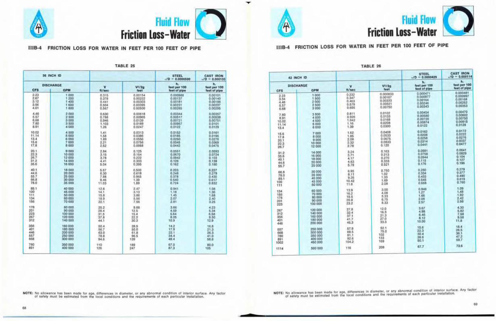
Fluid FlowFriction Loss-Water
Fluid FlowFriction Loss -Water
IllB-4 FRICTION LOSS FOR WATER IN FEET PER 100 FEET OF PIPE
TABLE 25
36 INCH 10 STEEL CAST IRONdO 0.0000500 dO 0.000133
DISCHARGEV
h, h,
CFSV2/2g feet per 100 feet per 100
GPM ft/sec feet feet of pipe feet of pipe
2.23 1000 0.315 0.00154 0.000988 0.001012.87 1200 0.378 0.00222 0.00137 0.001403.12 1400 0.441 0.00303 0.00181 0.001863.56 1600 0.504 0.00395 0.00231 0.002374.01 1800 0.567 0.00500 0.00285 0.00295
4.46 2000 0.630 0.00618 0.00344 0.003575.57 2500 0.788 0.00965 0.00517 0.005386.68 3000 0.946 0.0139 0.00721 0.007517.80 3500 1.103 0.0189 0.00957 0.01018.91 4000 1.26 0.0247 0.0122 0.0129
10.02 4500 1.41 0.0313 0.0152 0.016111.14 5000 1.58 0.0386 0.0185 0.019613.4 6000 1.89 0.0556 0.0260 0.027615.6 7000 2.21 0.0756 0.0345 0.036917.8 8000 2.52 0.0988 0.0442 0.0475
20.1 9 000 2.84 0.125 0.0551 0.059322.3 10000 3.15 0.154 0.0670 0.072426.7 12000 3.78 0.222 0.0942 0.10331.2 14000 4.41 0.303 0.126 0.13935.6 16000 5.04 0.395 0.162 0.180
40.1 18000 5.67 0.500 0.203 0.22744.6 20 000 6.30 0.618 0.248 0.27955.7 25 000 7.88 0.965 0.378 0.43066.8 30000 9.46 1.39 0.540 0.61778.0 35 000 11.03 1.89 0.724 0.832
89.1 40 000 12.6 2.47 0.941 1.08100 45000 14.1 3.13 1.18 1.36111 50 000 15.8 3.86 1.45 1.68134 60000 18.9 5.56 2.07 2.40156 70000 22.1 7.56 2.81 3.25
178 80000 25.2 9.88 3.66 4.23201 90000 28.4 12.5 4.59 5.34223 100000 31.5 15.4 5.64 6.58267 120000 37.8 22.2 8.05 9.50312 140000 44.1 30.3 10.9 12.9
356 160000 50.4 39.5 14.2 16.8401 180000 56.7 50.0 17.9 21.3446 200000 63.0 61.8 22.1 26.3557 250000 78.8 96.5 34.4 41.0668 300 000 94.6 139 49.4 58.8
780 350 000 110 189 67.0 80.0891 400 000 126 247 87.3 105
NOTE: No allowance has 「 ・ セ ョ made for age, differences in diameter, or any abnormal condition of interior surface. Any factorof safety must be estimated from the local conditions and the requirements of each particular installation.
68
s
IllB-4 FRICTION LOSS FOR WATER IN FEET PER 100 FEET OF PIPE
TABLE 26
STEEL CAST IRON42 INCH 10 dO セ 0.0000429 dO セ 0.000114
h, h,DISCHARGE V V2/2g feet per 100 feet per 100
CFS GPM ft/sec feet feet of pipe feet of pipe
2.23 1000 0.232 0.000833 0.000471 0.000481
3.34 1500 0.347 0.00187 0.000977 0.000997
4.46 2000 0.463 0.00333 0.00164 0.00168
5.57 2 SOD 0.579 0.00521 0.00246 0.00252
6.68 3000 0.695 0.00750 0.00343 0.00353
7.80 3 SOD 0.811 0.0102 0.00454 0.00470
8.91 4000 0.926 0.0133 0.00560 0.00602
10.02 4500 1.042 0.0169 0.00720 0.00750
11.14 5 000 1.16 0.0208 0.00674 0.00915
13.4 6 000 1.39 0.0300 0.0122 0.0128
15.6 7 000 1.62 0.0408 0.0162 0.0172
17.8 8 000 1.85 0.0533 0.0208 0.0222
20.1 9 000 2.08 0.0675 0.0258 0.0276
22.3 10 000 2.32 0.0833 0.0314 0.0337
26.7 12 000 2.78 0.120 0.0441 0.0477
31.2 14000 3.24 0.163 0.0591 0.0641
35.6 16000 3.71 0.213 0.0758 0.0829
40.1 18 000 4.17 0.270 0.0944 0.104
44.6 20 000 4.63 0.333 0.115 0.127
55.7 25000 5.79 0.521 0.176 0.196
66.8 30 000 6.95 0.750 0.250 0.279
78.0 35000 8.11 1.02 0.334 0.377
89.1 40 000 9.26 1.33 0.433 0.490
100 45 000 10.42 1.69 0.545 0.619
111 50000 11.6 2.08 0.668 0.760
134 60000 13.9 3.00 0.946 1.09
156 70 000 16.2 4.08 1.27 1.48
178 80 000 18.5 5.33 1.66 1.92
201 90 000 20.8 6.75 2.08 2.42
223 100000 23.2 8.33 2.57 2.98
267 120000 27.8 12.0 3.67 4.30
312 140000 32.4 16.3 4.98 5.82
356 160000 37.1 21.3 6.46 7.58
401 180000 41.7 27.0 8.12 9.58
446 200 000 46.3 33.3 10.00 11.8
557 250 000 57.9 52.1 15.6 18.4
668 300 000 69.5 75.0 22.3 26.5
780 350000 81.1 102 30.4 36.1
891 400000 92.6 133 39.6 47.2
1002 450 000 104.2 169 50.1 59.7
1114 500 000 116 208 67.7 73.6
NOTE: No allowance has been made for age, differences in diameter, or any abnormal condition of ェ ョ エ セ イ ゥ ッ イ sU,rface. Any factorof safety must be estimated from the local conditions and the requirements of each partlcular installation.
69

Fluid FlowFriction Loss -Water
Fluid FlowFriction Loss -Water
IIIB-4 FRICTION LOSS FOR WATER IN FEET PER 100 FEET OF PIPE IIIB-4 FRICTION LOSS FOR WATER IN FEET PER 100 FEET OF PIPE
TABLE 27
48 INCH 10 STEEL CAST IRONdO 0.0000375 dO 0.000100
DISCHARGE h, h,V V2/2gCFS GPM ft/sec feet per 100 feet per 100feet feet of pipe feet of pipe3.34 1500 0.266 0.00110 0.0005084.46 0.0005212000 0.355 0.00195 0.000855 0.0008835.57 2500 0.443 0.00305 0.001296.68 3000 0.001330.532 0.00440 0.001807.80 3500 0.001850.621 0.00598 0.00238 0.00245
8.91 4000 0.709 0.00782 0.0030410.02 0.003144500 0.798 0.00989 0.00378 0.0039111.14 5000 0.887 0.01221 0.00458 0.0047413.4 6000 1.064 0.0176 0.0063615.6 7000 1.24 0.006670.0239 0.00844 0.00890
17.8 8000 1.42 0.0313 0.010820.1 9000 0.01141.60 0.0396 0.013422.3 10000 0.01421.77 0.0489 0.016326.7 12000 0.01732.13 0.0703 0.0229 0.024431.2 14000 2.48 0.0957 0.0305 0.032735.6 16000 2.84 0.125 0.0391 0.042240.1 18000 3.19 0.158 0.048844.6 20000 3.55 0.195
0.05290.0598 0.064855.7 25000 4.43 0.305· 0.0910 0.099666.8 30000 5.32 0.440 0.128 0.142
78.0 35000 6.21 0.598 0.172 0.19289.1 40000 7.09 0.782 0.222 0.248100.2 45000 7.98 0.989 0.278111.4 50000 8.87 1.2210.314
0.341 0.384134 60000 10.64 1.76 0.484 0.548156 70000 12.4 2.39 0.652 0.742178 80000 14.2 3.13 0.849 0.968201 90000 16.0 3.96 1.06 1.22223 100000 17.7 4.89 1.30267 120000 21.3 7.03
1.501.87 2.15
312 140000 24.8 9.57 2.51 2.92356 160000 28.4 12.5 3.26 3.81401 180000 31.9 15.8 4.11446 200000 4.8335.5 19.5 5.05 5.97557 250000 44.3 30.5 7.88 9.28668 300000 53.2 44.0 11.3780 350000 13.462.1 59.8 15.3 18.2891 400000 70.9 78.2 20.0 23.71002 450000 79.8 98.9 25.21114 500000 29.988.7 122.1 31.1 36.8
1225 550000 97.5 148 37.6 44.51337 600000 106.4 176 44.7 53.0
NOTE: No allowance has 「 ・ セ ョ made for age, differences in diameter, or any abnormal condition of interior surface. Any factorof safety must be estimated from the local conditions and the requirements of each particular installation.
70
•
TABLE 28
54 INCH 10 STEEL CAST IRONe/O = 0.0000333 dO = 0.0000889
DISCHARGE h, h,V V2/2g feet per 100 feet per 100
CFS GPM ft/sec feet feet of pipe feet of pipe
4.46 2000 0.280 0.00122 0.000488 0.0004985.57 2500 0.350 0.00191 0.000733 0.0007486.68 3000 0.420 0.00274 0.00102 0.001047.80 3500 0.490 0.00374 0.00134 0.001388.91 4000 0.560 0.00488 0.00172 0.00177
Q セ N P R 4500 0.630 0.00618 0.00213 0.002201 .14 5000 0.700 0.00762 0.00257 0.0026613.4 6000 0.840 0.01098 0.00358 0.0037315.6 7000 0.981 0.0149 0.00476 0.0049917.8 8000 1.121 0.0195 0.00610 0.00642
20.1 9000 1.26 0.0247 0.00760 0.0080022.3 10 000 1.40 0.0305 0.00920 0.0097026.7 12000 1.68 0.0439 0.0129 0.013731.2 14000 1.96 0.0598 0.0171 0.018235.6 16000 2.24 0.0781 0.0219 0.0234
40.1 18000 2.52 0.0988 0.0273 0.029444.6 20000 2.80 0.122 0.0333 0.036055.7 25000 3.50 0.191 0.0504 0.055066.8 30000 4.20 0.274 0.0713 0.078278.0 35000 4.90 0.374 0.0958 0.106
89.1 40000 5.60 0.488 0.124 0.137100.2 45000 6.30 0.618 0.155 0.172111.4 50000 7.00 0.762 0.189 0.211134 60000 8.40 1.098 0.267 0.301156 70000 9.81 1.49 0.358 0.408
178 80000 11.21 1.95 0.465 0.530201 90000 12.6 2.47 0.586 0.668223 100000 14.0 3.05 0.715 0.820267 120000 16.8 4.39 1.02 1.18312 140000 19.6 5.98 1.38 1.59
356 160000 22.4 7.81 1.80 2.07401 180000 25.2 9.88 2.26 2.62446 200000 28.0 12.2 2.77 3.22557 250000 35.0 19.1 4.32 5.01668 300000 42.0 27.4 6.19 7.23
780 350000 49.0 37.4 8.40 9.82891 400000 56.0 48.8 11.00 12.8
1002 450000 63.0 61.8 13.9 16.21114 500000 70.0 76.2 17.0 20.01225 550000 77.0 92.3 20.6 24.2
1337 600000 84.0 109.8 24.5 28.81448 650000 98.1 129 28.7 33.71560 700000 112.1 149 33.2 39.0
NOTE: No allowance has been made for age, differences in diameter, or any abnormal condition of interior surface. Any factorof safety must be estimated from the local conditions and the requirements of each particular installation.
71
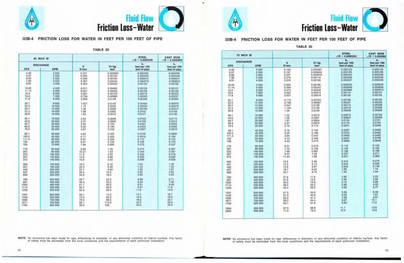
Fluid FlowFriction Loss-Water
Fluid FlowFriction Loss -Water
IllB-4 FRICTION LOSS FOR WATER IN FEET PER 100 FEET OF PIPE IllB-4 FRICTION LOSS FOR WATER IN FEET PER 100 FEET OF PIPE
TABLE 29
60 INCH 10 STEEL CAST IRONdO = 0.0000300 dO = 0.0000800
DISCHARGE h, h,V V2/2g feet per 100 feet per 100
CFS GPM ft/sec feet feet of pipe feet of pipe
4.46 2000 0.227 0.000800 0.000293 0.0002985.57 2500 0.284 0.00125 0.000440 0.0004466.68 3000 0.340 0.00180 0.000612 0.0006217.80 3500 0.397 0.00245 0.000810 0.0008248.91 4000 0.454 0.00320 0.00103 0.00105
10.02 4500 0.511 0.00405 0.00128 0.0013111.14 5000 0.567 0.00500 0.00155 0.0015913.4 6000 0.681 0.00720 0.00216 0.0022315.6 7000 0.794 0.00980 0.00285 0.0029717.8 8000 0.908 0.0128 0.00365 0.00382
20.1 9000 1.021 0.0162 0.00454 0.0047622.3 10 000 1.13 0.0200 0.00550 0.0057926.7 12000 1.36 0.0288 0.00766 0.0081531.2 14000 1.59 0.0392 0.0102 0.010835.6 16000 1.82 0.0512 0.0131 0.0140
40.1 18000 2.04 0.0648 0.0163 0.017444.6 20000 2.27 0.0800 0.0198 0.021255.7 25000 2.84 0.125 0.0301 0.032566.8 30000 3.40 0.180 0.0424 0.046078.0 35000 3.97 0.245 0.0567 0.0618
89.1 40000 4.54 0.320 0.0730 0.0800100.2 45000 5.11 0.405 0.0916 0.100111.4 50000 5.67 0.500 0.112 0.124134 60000 6.81 0.720 0.158 0.176156 70000 7.94 0.980 0.213 0.237
178 80000 9.08 1.28 0.275 0.307201 90000 10.21 1.62 0.344 0.387223 100000 11.3 2.00 0.420 0.478267 120000 13.6 2.88 0.600 0.688312 140000 15.9 3.92 0.806 0.930
356 160000 18.2 5.12 1.04 1.20401 180000 20.4 6.48 1.32 1.52446 200000 22.7 8.00 1.62 1.87557 250000 28.4 12.5 2.52 2.92668 300000 34.0 18.0 3.60 4.20
780 350000 39.7 24.5 4.88 5.71891 400000 45.4 32.0 6.34 7.42
1002 450000 51.1 40.5 8.01 9.401114 500000 56.7 50.0 9.87 11.61225 550000 62.4 60.5 11.9 14.0
1337 600000 68.1 72.0 14.1 16.71448 650000 73.8 84.5 16.6 19.61560 700000 79.4 98.0 19.2 22.71671 750000 85.1 112.6 22.0 26.01782 800000 90.8 128 25.0 29.6
NOTE: No allowance has been made for age, differences in diameter, or any abnormal condition of interior surface. Any factorof safety must be estimated from the local conditions and the requirements of each particular installatIon.
72
$
TABLE 30
72 INCH 10STEEL CAST IRON
dO = 0.0000250 dO = 0.000066
DISCHARGE hi h,V V2/2g feet per 100 feet per 100
CFS GPM It/sec feet feet of pipe feet of pipe
4.46 2000 0.158 0.000387 0.000123 0.0001255.57 2500 0.197 0.000604 0.000183 0.0001866.68 3000 0.237 0.000870 0.000254 0.0002587.80 3500 0.276 0.00118 0.000336 0.0003428.91 4000 0.316 0.00155 0.000427 0.000435
10.02 4500 0.355 0.00196 0.000530 0.00054011.14 5000 0.394 0.00242 0.000640 0.00065613.4 6000 0.473 0.00348 0.000890 0.00091315.6 7000 0.552 0.00474 0.00118 0.0012117.8 8000 0.631 0.00619 0.00150 0.00155
20.1 9000 0.710 0.00783 0.00186 0.0019322.3 10000 0.789 0.00967 0.00227 0.0023526.7 12000 0.947 0.0139 0.00313 0.0032931.2 14 000 1.104 0.0189 0.00418 0.0043835.6 16000 1.26 0.0248 0.00538 0.00563
40.1 18000 1.42 0.0313 0.00673 0.0070344.6 20000 1.58 0.0387 0.00822 0.0085955.7 25000 1.97 0.0604 0.0124 0.013166.8 30000 2.37 0.0870 0.0173 0.018478.0 35000 2.76 0.118 0.0231 0.0248
89.1 40000 3.16 0.155 0.0297 0.0320100.2 45000 3.55 0.196 0.0370 0.0402111.4 50000 3.94 0.242 0.0450 0.0493134 60000 4.73 0.348 0.0637 0.0700156 70 000 5.52 0.474 0.0850 0.0940
178 80 000 6.31 0.619 0.110 0.122201 90 000 7.10 0.783 0.138 0.154223 100000 7.89 0.967 0.168 0.189267 120000 9.47 1.39 0.237 0.271312 140000 11.04 1.89 0.321 0.365
356 160000 12.6 2.48 0.414 0.475401 180000 14.2 3.13 0.522 0.600446 200000 15.8 3.87 0.642 0.736557 250000 19.7 6.04 1.00 1.14668 300000 23.7 8.70 1.42 1.64
780 350000 27.6 11.8 1.92 2.23891 400000 31.6 15.5 2.50 2.90
1002 450000 35.5 19.6 3.16 3.661114 500000 39.4 24.2 3.88 4.521225 550000 43.4 29.2 4.69 5.47
1337 600000 47.3 34.8 5.56 6.501448 650000 51.3 40.8 6.52 7.611560 700000 55.2 47.4 7.56 8.811671 750000 59.2 54.4 8.67 10.11782 800000 63.1 61.9 9.83 11.5
1894 850000 67.0 69.9 11.1 13.02005 900000 71.0 78.3 12.4 14.6
NOTE: No allowance has been made for age, differences in diameter, or any abnormal condition of interior surface. Any factOrof safety must be estimated from the local conditions and the requirements of each particular installation.
73

Fluid FlowFriction Loss -Water
Fluid FlowFriction Loss -Water
IIIB-4 FRICTION LOSS FOR WATER IN FEET PER 100 FEET OF PIPE
TABLE 31
IIIB-5 RESISTANCE COEFFICIENTS FOR VALVES AND FITTINGS
TABLE 32(a)
-
75
1セMKjNNャャjLAMBBBBAZMGMNャNMGセセ.3.5 1 2 4
D
GセAiiセセAAi.8K.6.3.5 , 2 4
D
BRANCHFLOW
SCREWEDTEE
セ l i n eセ FLOW
PIPE - ヲヲゥセュ K 21-+-+"'+\. \SCREWED :-......
iTt:'; i lRETURN G セ ゥ ェ ャ ᄃ セ ゥ ェ-'!J!.Y/ BEND⦅ セ 63 .5 1 2 4
セ FLANGED.4
2
BELL- MOUTHINLET OR REDUCER
K = 0.05 セr e g u l a rSCREWED .6
\ 45° ELL. .4gJjfiEIBk S セ.23 .5 1 2 4
D
セ ZZャZセセセ| セイIセloセnセgセセGSヲヲセ・ャャセセSO セ RADIUS .2UAREK eセセNセd INLET セ B H +- FLANGED
I セ 45° ELL. "!",-'-21;-'--'-74 MGMMAZVNオNjG[G[ZPZMGセRP
D
INWARD PROJECTINGK = 1.0
i""'--
kNZNセSセァiヲセセセセセ.5 , D 2 4
LONG .8
h = K V' FEET OF FLUID29
REGULARSCREWED90° ELL.
NOTE: K DECREASES WITHINCREASING WALL THICKNESS OFPIPE AND ROUNDING OF EDGES
I -1lJjr--. セ RADIUS .6
iijiセM '" SCREWED 4
.. ,90° ELL. . エZエZ。Zセ]A]エセセI \ NSセ-r I s=i .23 .5 1 D 2 4
.....,;:---+
NOTE: No allowance has been made for age, differences in diameter, or any abnormal condition of interior surface. Any factorof safety must be estimated from the local conditions and the requirements of each particular installation.
84 INCH 10STEEL CAST IRON
.10 = 0.0000214 .10 = 0.0000571
OISCHARGE hi hiV V2/2g feet per 100 feet per 100
CFS GPM ft/sec feet feel of pipe feet of pipe
6.68 3000 0.174 0.000469 0.000121 0.0001228.91 4000 0.232 0.000833 0.000203 0.000206
11.14 5000 0.289 0.00130 0.000306 0.00030913.4 6000 0.347 0.00188 0.000425 0.00043215.6 7000 0.405 0.00255 0.000562 0.000573
17.8 8000 0.463 0.00333 0.000717 0.00073120.1 9000 0.521 0.00422 0.000891 0.00091022.3 10 000 0.579 0.00521 0.00108 0.0011026.7 12000 0.695 0.00750 0.00150 0.0015431.2 14000 0.811 0.01021 0.00199 0.00205
35.6 16000 0.926 0.0133 0.00255 0.0026240.1 18000 1.042 0.0169 0.00316 0.0032744.6 20000 1.16 0.D208 0.00384 0.0040055.7 25000 1.45 0.0326 0.00579 0.0060666.8 30000 1.74 0.0469 0.00810 0.00858
78.0 35000 2.03 0.0638 0.0108 0.011589.1 40000 2.32 0.0833 0.0139 0.0148
100.2 45000 2.61 0.105 0.0174 0.0185111.4 50000 2.89 0.130 0.0212 0.0226134 60000 3.47 0.180 0.0298 0.0321
156 70000 4.05 0.255 0.0398 0.0431178 80000 4.63 0.333 0.0513 0.0558201 90000 5.21 0.422 0.0640 0.0700223 100000 5.79 0.521 0.0781 0.0660267 120000 6.95 0.750 0.111 0.122
312 140000 8.11 1.021 0.149 0.166356 160000 9.26 1.33 0.193 0.216401 180000 10.42 1.69 0.242 0.272446 200000 11.6 2.08 0.297 0.334557 250000 14.5 3.26 0.458 0.516
668 300000 17.4 4.69 0.649 0.740780 350000 20.3 6.38 0.880 1.00891 400000 23.2 8.33 1.14 1.30
1002 450000 26.1 10.5 1.44 1.651114 500000 28.9 13.0 1.78 2.04
1225 550000 31.8 15.8 2.14 2.471337 600000 34.7 18.0 2.54 2.941448 650000 37.6 22.0 2.97 3.451560 700000 40.5 25.5 3.43 4.001671 750000 43.4 29.3 3.93 4.58
1782 800000 46.3 33.3 4.47 5.201894 850000 49.2 37.6 5.04 5.872005 900000 52.1 42.2 5.64 6.582117 950000 55.0 47.0 6.29 7.322228 1 000000 57.9 52.1 6.95 8.10
74

Fluid FlowFriction Loss -Water
Fluid flowFriction Loss -Water
20 1'\ BASKET 1.5r L -( "\!K
[ i'I STRAINER 1 r-..
r1 SCREWED10
K .66 JII
セ.3 .6 1 2 4
.41 2 D 4 6 10 20
15
10 I'-... FOOT 1111K I.J
VALVE 1.0
6 In't .6
GLOBE4 Iセ \\cJbp)lhl K -1
FLANGED 12 4 6 10 20 .4
VALVE1 2 4 6 10 20
D D.3
セセcrewGd K: I"-., .3 2 4vi .2-.nm-
K .1 1<::::7 .1---- -- -
GATE .06 \..J{K .06
VALVE .04 .04
FLANGED COUPLINGS.03
1 2 4 6 10 20 AND UNIONS.03.3 6 1 2 4
i|セ6 ....r --. REDUCING BUSHING
/--'"
AND COUPLINGL セ B L G 4 1-f--V, -=F"V, ィ ] k セ Gセ M M •. K 1--.
2 .....r 2g........
SWING SCREWED 1CHECK .3 .6 1 2 4 USED AS REDUCER K = 0.05 - 2.0VALVE 3 SEE ALSO IIIB-7
K 2 USED AS INCREASER LOSS IS UPTO 40% MORE THAN THAT CAUSED
FLANGED '1BY A SUDDEN ENLARGEMENT
2 4 6 '0 20
".. '" SCREWED 6
iセセMセSUDDEN ENLARGEMENT
セ Rr-4
'- t-K
,/ 21'-
,L ,h}I - I\. h = (V, - V,)' FEET OF FLUID1
5iJ".3 .6 , 2 4 2g
4'-
SEE ALSO EQUATION (5)K 3 IF A, = 00 SO THAT V, = 0
ANGLEVALVE
2h = V,'
FLANGED 1.5, 2 4 6 10 20FEET OF FLUID
D2g
76
IIIB-5 RESISTANCE COEFFICIENTS FOR VALVES AND FITTINGS
TABLE 32(b)
h = K V' FEET OF FLUID2g
IIIB-5 RESISTANCE COEFFICIENTS FOR VALVES AND FITTINGS
TABLE 32(c)
Approximate Range of Variation For K
Fitting Range of Variation
90 Deg, Elbow Regular Screwed ± 20 per cent above 2 inch size
Regular Screwed ± 40 per cent below 2 inch size
Long Radius, Screwed ± 25 per cent
Regular Flanged ± 35 per centLong Radius, Flanged ± 30 per cent
45 Deg. Elbow Regular Screwed ± 10 per centLong Radius, Flanged ± 10 per cent
180 Deg. Bend Regular Screwed ± 25 per centRegular Flanged ± 35 per centLong Radius, Flanged ± 30 per cent
Tee Screwed, Line or Branch Flow ± 25 per centFlanged, Line or Branch Flow ± 35 per cent
Globe Valve Screwed ± 25 per cent
Flanged ± 25 per cent
Gate Valve Screwed ± 25 per cent
Flanged ± 50 per cent
Check Valve Screwed ± 30 per cent
Flanged\+ 200 per cent( - 80 per cent
Sleeve Check Valve Multiply flanged values by .2 to .5
Tilting Check Valve Multiply flanged values by .13 to .19
Drainage Gate Check Multiply flanged values by .03 to .07
Angle Valve Screwed ± 20 per cent
Flanged ± 50 per cent
Basket Strainer ± 50 per cent
Foot Valve ± 50 per cent
Couplings ± 50 per cent
Unions ± 50 per cent
Reducers ± 50 per cent
NOTES ON THE USE OF TABLES 32(a), (b) and (c):
1. The value of D given in the charts is nominal IPS (Iron Pipe Size).2. For velocities below 15 feet per second, check valves and foot valves will be only partially open and will
exhibit higher values of K than that shown in the charts.
77

"co
セセ
....:::lD,U1
::DmIJIIJI
セZomoom ....." ..." _.- C"Io _m _.Z e:::t-I =IJI
" ....o e:::t::D en .....
" en =-::I I Ezs: .....G>_=IJI 51: セ
K, = 1.129K, = 1.265
1.440
セ ッセ ッ ッ
K, = 0.47;K, = 0.684
·OPTIMUM VALUE OF a INTERPOLATED
セ o B セ T U B
K, = 0.130 K, = 0.236K, = 0.165 K, = 0.320
セ R N U B
K, = 0.066K, =0.154
K,= 0.042K,= 0.062
K, = 0.143K, = 0.227
セ B
TABLE 33. RESISTANCE COEFFICIENTS FOR MITER BENDS ATREYNOLDS NUMBER;; 2.25 X 10⁵
K, = 0.150K, = 0.268
K, aiD K, I K, aiD I K, K, aiD K, K,0.510 22.5" 1.186 0.120 0.294
30"1.23 0.195 0.347 1,23 0.157 0.30045" 0.415 1.40 0.125 0.252 1.44 0.196 0.320 3D" 1.67 0.156 0.378
0.384 1.50' - 0.250 1.67 0.150 0.300
セ2.37 0.143 0.264
0.377 1.63 0.124 0.266 1.70· 0.149 0.299 3.77.....L0.160_0.2420.376 22.5" 1.86 0.117 0.272 1.91 0.154 0.3120.390 2.325 0.096 0.317 2.37 0.167 0.3370.429 a 2.40' 0.095 - 3D" 2.96 0.172 0.3420.426 2.91 0.108 0.317. 4.11 0.190 0.3540.460 3,49 0.130 0.318 4.70 0.192 0.3600-455 4.65 0.148 0.310 6.10 0.201 0.360
5.59 0.392 0.444 6.05 0.142___0.313
6.28.-..0.399_0.444
K, = 0.016 I K, = 0.034K, = 0.024 K, = 0.044
K, = 0.112K, = 0.284
セ -t:
セ U Pセ B
AO
K, = RESISTANCE COEFFICIENT FOR SMOOTH SURFACEK, = RESISTANCE COEFFICIENT FOR ROUGH SURFACE, セ セ 0.0022
-1
" .
.....-=_.=-.....-CD:E
セセ
........_.C"I-_.e:::t=....e:::t=I
I...cmG>::Dmm
8lD,U1>
lD::DmmZIJIc-i j i セ0>"Zoc:mセ ッ"0Om::D"3:!!c Q-m>z3:-1m lJl-I"mo::D::D
lDo
amセセセセa
cnoooo$;00000 0000
0 ............ 1'\)
o セ ッ セ ッ
--l::r:, ,
01'"
a セ '" w -I u,
./'I"" ... .--'. _ -r- ] ] セ M/ yMLセZN[ZZNNNNNGM . '-,
(7 1/ / /'
1/ ' /1/ / セ •I' [ セM -0 :1-
I I ," I / HAセ t,II L セ N セ, Pt' liT. セ セ
III r1'8 セ\ \ _セセ L セ-1.,1 X
\ \ \ セ Jl'1'ii
--..1_ セ セ \ \ _...\....1.1....1QセNNNlMMMセ
a
co
セ
a
m
セ
a
'"
....
'"
'"
...
cl::D 01
;<l

....-=_.a.....-o==
セセ
....-_.C"I-_.o=p-Oenen
I
IEnr-
......lD,U1lD
:xlmenen
en-lZ A Z セ00Om
:to・ ョ セC:TI:xlTlTI-:l>Qommz:l>Cil-I
TI:xl 0m:xl-<ZlDomrZ00en enZo!:l TI
III c:Z
1\)-• TI1\)0U1:xlX:!:.... 00-'" :I>
:!:m-Im:xl
:I>Zo
o
'"oo
'"'""'"o"セ'"'" セ
oセ
o
oo'"o
'"'"'"
'""'"
'"'"'"
'"o
'"o
•1
-,
, I\\
M M M M ッ セ セ Q\,
セ_:-:::t-'
, 1" -!i:". =-
セoセセ, ,;: .'
"'", :::l"(';,1>0' 1/
セ セBN .Nセ xセ セiGs
\ '\ "'-
f\ ...
JJ'\
,0
セNャ
セl
I
セNBN-
iセ
セlM I-0
1\
'"JJ,
JJ
0
,
I 1\
0
セ
1\
0
セ
IL- I
'""'""'"
'"'"'"
coo
rセo
ex>o
セ
セセ
....-_.C"I-_.o=p-Oen ....en -=I _.
IE '7:- e:::t
===
53lD,en
o TI:xl(;-I
oZ
5enenTIo:xl
セ"tlmTI
セZCl
J'v,' en29
セL I I I I I 1 I I 1 1 I J-.!. I 1 I I I I I I I I I I I I I I I 1 I J 1 1 '-,I- 0'110 .1 セNセoB I セーo 0040,1 セQUP -I...... UPPER LIMIT ·
I- 0, - 0,)/21 I -. -.L ·1 t- ·l- f- l-
V --- -l- +-- -I- --J-L i- - I- ......!- !-l tlWf:R tt f
1/ V -j ":"
I-j f J I I I I I 1 1 1 1 1 , , , , , , , , , , , , ,.l , II - 70 80 90 100 110 120 130 140 150 160 170 1E- I
j I 1/ -8
i J1/ - .J11.f-; 1/, II I J -
vセ..m VI
7if .0,
::.'-- GIBSON: ___- OJ-- 0,
81-- , I - L.li,1-, I L -
ヲMlセ Uf- I I ·
i ,
'1,
, · i RUSSELL:I-- - -=:L' L=6" _._-_
4. i I i-- ,( °S·22 - - -1%-- r, L= 12"---- _.-
セ L セ K - 3.5 tan VII \ セ / - t jvセェ
L= 18"--- ._.-
3 -セ|エG|jii - L
01tan 0/2 = (0, - O,l/2L
, '
l- · - I-セ IV ィ]k{iMHセjイセセ ]k{HセjMQI 0, - 0,)/2 L
-/ (,--I- - ;j ,\%
10.'10 '1 ッGNセッB I' "0'30' 0040'I' oG⦅セo - セoGhl-
t-, I I J I 1 I I I , I ,. I
0.3
0.1
0.0o 10 20 30 40 50 60
o IN DEGREES
RESISTANCE COEFFICIENTS FOR INCREASERS AND DIFFUSERS
o.
004
o.
o.
0.2
o.
1.
1.
0.7
1.2
K
セ

Fluid FlowFriction Loss -Water
Fluid FlowFriction Loss- Other Fluids
IIIB-? FRICTION LOSS FOR PIPE FITTINGS IIIC -CALCULATION OF FRICTION LOSS FOR ANY FLUID IN STEELOR WROUGHT IRON PIPES
セ ヲ -:>
-r5
':=-- c.:=- -I-- c5 __ ""I '"> OJ
t>""IIセ -
-
\
1\\
1\
\
r\'""i'-. M = Friction loss modulus for 100 feet of pipe
LIp = Pressure loss in pounds per square inchper 100 feet of pipe
SG = Specific gravity of fluid at 60° F
The loss due to pipe friction may be obtained as
The bottom scale of each chart represents flow ingallons per minute, gpm. An auxiliary top scaleshows the average velocity in the pipe in feet persecond. Read vertically from the gpm scale to findthe corresponding velocity In feet per second. Thevertical scales, labeled "Friction Loss Modulus for100 Feet of Pipe", represent values of the ratio
Friction loss moduli for laminar flow are shown bythe 45-degree lines in the upper left hand portionof each chart. Moduli for turbulent flow are shownby the steeper curves in the lower right hand por-tion. Both of these regions represent stable statesof flow. A diagonal line separates the regions oflaminar and turbulent flow and represents the criti-cal zone, a region in which it is difficult to predictthe state of flow and hence, the friction loss. Thecritical zone usually represents a region of un-stable flow. The critical zone line gives approxi-mate moduli on the high side for this region ofunstable flow.
(11 )
(12)h, = 2.31 M
LIp = M x SGfollows:
and
To use the charts, proceed as follows:
(a) Select the chart for the size of pipe in question.
(b) Follow the vertical line representing the flow ingpm to its intersection with the desired viscositycurve, and read the modulus at the left.
(c) If the vertical line representing the flow in gpmdoes not intersect the viscosity line in either turbu-lent or laminar flow, use the intersection with thecritical zone line.
(d) Compute the friction loss in pressure drop orhead, as desired, from Equations (11) or (12)above. These equations are repeated on each chart.
The chart for Y2-inch pipe, Fig. II1C-l,may be usedto illustrate the method for finding the frictionmodulus for a flow of 10 gpm at viscosities of 50SSU, 150 SSU and 300 SSU. For 50 SSU, themodulus value is 56. For 300 SSU, the modulusvalue is 119. The 10 gpm line does not intersect the150 SSU line in either the laminar or turbulent re-gion. Therefore, using the intersection of the 10gpm line with the critical zone line, the modulusvalue is 68.
The range of the laminar flow region of each chartmay be indefinitely increased since the friction lossmodulus varies directly with the viscosity (above1000 SSU) and the rate of flow. This does not applyto the turbulent flow region. For example, let it berequired to find the friction modulus for the flow ofa fluid of 20,000 SSU viscosity at a rate of 0.10 gpmin new Y2-inch steel pipe, Fig. IIIC-l. The modulusfor a flow of 1.0 gpm and 10,000 SSU is 395. Therequired modulus will be
M =395 x 20,000 x 0.10 =7910,000 1.0
An example illustrating the use of the charts for
wherein
h, = Friction head loss In feet of fluid per 100feet of pipe
The other quantities are as listed under Equation(10).
(10)M = LIpSG
wherein
The pipe friction charts, Figs. IIIC-l thru II1C-13incl., show friction-loss moduli for the incompres-sible flow of viscous fluids, including water, in sev-eral sizes of new clean steel or wrought iron pipeshaving Schedule 40 wall thickness. Each chart cov-ers the losses for a single size of pipe based on thekinematic viscosity in centistokes (cs). As viscosityis frequently given in Seconds Saybolt Universal,(SSu), corresponding rounded values at 100" Fareshown except in the case of low viscositites whereno accurate SSU equivalents exist. Further infor-mation on viscosity and commonly accepted vis-cosity values for liquids will be found in SectionII-C. No allowance has been made for abnormalconditions of interior surface or installation nor forthe deterioration with age. (See Section lilA.)
U)a:wo::lCWa:a:oLL
セZW(3ii:LLWoowoz
セii)wa:
"'M
"'N
oM
oN
o"'0;
•82 83

Fluid FlowFriction Loss-Other Fluids
Fluid FlowFriction Loss-Other Fluids
/, 1/ 1/1 lljlャllセセゥャlセlljセiNjNゥNNNNljRMlNNlllャNNlNNNNNャNNNNNNャNNNlセMMMャMlNNNNNャNMGMZGRPGZMMGMMセSP
.3 .4 .5 .6.7.8 1.0 3 4 5 6 7 B 10
GALLONS PER MINUTE
FRICTION LOSS MODULUS FOR 100 FEET OF PIPE
PIPE VELOCITY FT. PER SEC.
30205 6 7 8 10
(I1/,\
IllC-1
b. Discharge Line. The friction loss modulus forthe 1V2-inch pipe (Fig. IIIC-5) is 44 and the inter-section shows the flow to be laminar. No additionalallowance for the fittings will be made here. Thepressure loss in the discharge pipe will be
An alternative solution is to use Table 34 to solvedirectly for pipe size by entering the tabie on page99 on the line for 50· gal/min. and movinghorizontally to the proper viscosity column. Underthe column headed 1000 SSU it can be seen thatthe 1V2-inch pipe which has a modulus of 43.8 istoo small, but the modulus for the 2-inch pipe is16.1, which is satisfactory. It can also be seen thatif additional allowance for the age of the pipe mustbe made so that a modulus of 15.0 or less is re-quired, it would be advisable to use a 2V2-inchsuction line, which has a modulus of only 7.9 andis satisfactory.
factory for the suction line, however, judgment willhave to be used to decide if local conditions requirean additional allowance for aging of the pipe,valves and fittings.
The pressure loss in the discharge line could alsohave been obtained from Table 34. The modulusfor 50 gal/min. of oil with a viscosity of 1000 SSUin an 1V2 -inch pipe is 43.8, which is approximatelythe same as obtained from Figure mC-5.
Therefore, the pressure at the pump dischargeflange will be
P =0 119 + 250 =0 369 psi
6P =0 44 x 0.9042 x 300 '" 119 psi100
the solution of a practical problem follows:
Example 4. Use of Charts for Friction Loss 01 AnyFluid. A pump is required to take oil from a ventedtank and deliver it at a rate of 50 gpm to a dis-tributing manifold as shown in Fig. mC-14. Thesuction line is 20 feet long including fittings. Thedischarge pipe is 1'I2-inch new steel, Schedule 40,300 feet long including fittings. The manifold is atthe same elevation as the centerline of the pumpand its pressure must be maintained at 250 psi.The oil has a viscosity of 1000 SSU and a gravityof 25 degrees API. The minimum desired suctionpressure at the pump inlet is 15 inches of mercuryvacuum and it is required that new steel, Schedule40 pipe be used, preferably size 1'I2-inch. It is re-quired to find the correct size for the suction pipeso as not to exceed 15 inches of mercury vacuumat the pump inlet and the pressure in pounds persquare inch at the discharge flange of the pump.
SOLUTION: a. Suction Line. The specific gravity ofthe oi I may be obtained from Section II B and isequal to 0.9042.
Mercury weighs 0.4898 Ib/cu in. at 60° F so thatthe maximum desired suction lift is 15 x 0.4898 =0
7.35 psi. The static lift at the minimum tank levelcorresponds to
10 [0.904 x 62.34J =0 3.91 psi144
The maximum allowable pressure drop in the suc-tion pipe will be 7.35 - 3.91 =0 3.44 psi. The re-quired friction loss modulus, by Equation (11) andneglecting the pipe fittings, will be
M =0 6P X 100SG Actual Length 01 Pipe
3.44 100=o--x-
0.904 20
=0 19.0 for 100 feet of pipe
The size of the suction pipe may be determined byselecting a size from the charts (Figs. I1IC-1-13incl.) such that the intersection of the 50 gpm linewith the 1000 SSU curve is at a modulus valueequal to or less than 19.0. The intersection on Fig.1I1-5 for 1'12-inch pipe is at a modulus value 44which is too high. The intersection on Fig. IIIC-6for 2-inch pipe is at a modulus value 16 which issatisfactory. Furthermore, the intersection is in theupper left hand portion of the chart showing thatthe flow will be laminar. A 2-inch pipe will be satis-
84 85
7

Fluid FlowFriction Loss-Other Fluids
Fluid FlowFriction Loss-Other Fluids
UIC-2 FRICTION LOSS MODULUS FOR 100 FEET OF PIPE UIC-3 FRICTION LOSS MODULUS FOR 100 FEET OF PIPE
PIPE VELOCITY FT. PER SEC. PIPE VELOCITY FT. PER SEC.
1/ / 1/ / セヲMOエ[Nエ\MOMMMvBセOGMヲG -nHvl-+/P,-Ll:=-':-:--L-l-LL--'.-L-LJ-Lj
R Q M B L L O L J L N O i セ f M i O h l N ー N O セ G A ^ J L ア N N ェ セ O セ C M G A ヲ M ャ ヲ O J N M エ M K M K E L N B N L G イ ] L s t [ N [ N e Z [ e [ Z Z N Z Z l Z N L N N Z N N p [ Z N i p N [ Z e N L N Z H セ P Z Z [ N X Z N R T Z N N B ⦅ i Z [ N N G N N Z [ d セ N I セ/ "/ c>' 'I'
3 4 5 6 7 8 10 2 3 4 5 6 7 8 10 20 20
30 40 50 60 7020
p.
3 4 5 6 7 8 102
3 4 5 6 7 8 910
GALLONS PER MINUTE2
1/ I,'
,3 ,4 ,5 ,6 ,7,8 1,0
,7 .8,91,0
30
rTTl I I 1;- I I I I I , , I I' '" I I I I I I I I I I I I I , , I I'" 'I "200 (43,2)
100 セ セ セ ,_
セ セ セ N セ Z エ R 4- /'70 r- セ 1/ '\; セ II60 roc, ./ /1 V-::/ V / / / / :/1/ /(f
セ セ セ / / / / 1/ 1/ i/ / MUᄚセeセェᄋウ[LゥェャセᄋセセセBDセセOセ。ᆪセiOセセs[セセ・セヲセセᄋG[ セイエᄆェv "" ""'V-40 L セ L i O 'I" ,
/ 'b'Y / 1"1 1/ 1'1_ 'I /Ii/ セ / GOセBLiOQW V / 1/ / 17 1/ セ
セ [ W セ ゥ O / / 4 4 iOiOiNGOセセKKMKMi
....> v;f>';I カ セ / / / / / / / lIW; /;
20 h Z N N j N i B ᆬ G [ G T W G ヲ M ᆬ j B L ᆬ M ィ T L T M ャ T J K B \ ィ ャ N ア N L ェ l M A M a セ h O M a M i ヲ A Q i M K K K K M i M M ャセ H'-hr-:H" ,/ 1/ セ B ./ V V I) I I/hIi: / V" 4 / ,,1/17 q, v /1/ 1/ / /ri wCl _ w '\.,]/ / / 4 fI.Jr-I/.ff,1FセMKMhMKKMMKMャo::l v ..;py カBセO / / / / / 1)17 ff/
セ x QYセD。セセセセQセセ。エRエ[。セVセエG^セセエエエZセエセセ l/) 8 ヲMhMPK\セカO '" / セl/) ::::l... 7 '=? '
,'V/ // / /f I;X is 6 hMᆬエWV^イャGGM「hセKMGイKセ^ヲMMvMhTMZvヲLhャャャイMhMヲMQhKKKMKMQ
l/) 0 5 / <f?'Y セL LLセゥOaセOコエOセATO]エコエOエャaャャG QセiZセャOエZセPセ]エ]エセᄆᄆェ::::l "" k セ / I" ,,>... セ セ L B セ .::::l II 4 エMMhセャゥBGMエMWGイᆬ、ッIALiOBM「BGイaMᆬGhaWTMKaイNaMMェLセGイLTMKMKKMKKMhiMKKMセc VI,' //,,' B セo c t-t'-t-kii=r-i'-t'i'H--/t-:>'1-l1"-H0-O v イ K a ャ ィ セ N '1/'--+-!-H-+--+-+-+++---+-I:; :5 3 lol'Y / / / "
II g hMMvGイ[ゥiGBLセッOMケGMhエNゥGPQZBZ y./'-Y4/7iy,./4-t.A--JA
II{j...,fl'lU--++$IIt-++-+-+-f--I-++---+--lZ lL 2 V V.V O セ / 1/ / 'f) I/, ,:;
o ./ V ,/ セ B B / / / $' t,;g t:; OQセ|[W / 7L / / jセ 'I
III セ c ^ O i O セ セ B G ォ [ セ G V-/'--b'nf'++--1/---Y/'-;r/+++-+-++-++--t-t-+-+-J-f--H
セ j セMセQOJWQQᄃセOVGWBセBセ GOセセYNアG_セOセャOセセセOセセOG iヲャAᄃbQeᄃᄃᄃAァセScri l:l1 ,0 BBBMエM[OLiヲMKMゥJKィセNLエMKMhMKMKKMKMKMKMKMKMKQMKMMKMャm 0,9,-' ......8 "./ :\ / 1/ I
J ,7 , ?/ ' / I I'l/) ,6 hMyGpILGM「aMMpaKMᆬTMMyMwMMfMKMエMKKiMhMKMhセセヲMKKKKMMャMMャ
9 ,5 セ セ i O ァ セ エ G J ヲ J ョ セ O セ L a ヲ D セ O 。 ] ] エ ] 。 ] 。 ] e 。 ] 。 ] エ e ] e セ ] s :,";7 -,.4 ",/ L. / 'i/
,3 <r·1 I
f-Y-+4,§I,4+--+'Il-I/-H-j l,-¥/Lft,'+-l-+-l-+-+-l-l-L-J.--L.L.L.L..-L...JLL.L.L-L-H/ /11 1" STEEL PIPE (1.049" I. D.)
,2 hM「ヲKMM[ゥッGGMエMエMKMGィャMyMMaMKMhKMKMエMKKイM[ZZN[NL]ZイZ[G[GZGZGGZ[ZNNャN[GZGZ[[GZZGGGGセZZNZTMMャ/ ャGMMiKGWMKMKMKQMKMMKMKMiMKKMKMhMhヲMKMMKMQGMKMhMャセ
I I
30
30 40 50202 3 4 5 6 7 8 10
GALLONS PER MINUTE
/ / / II,
v' / /' I ,/,1/ / '/ / I II,
,5 ,6 ,7,8 1,0
86 87
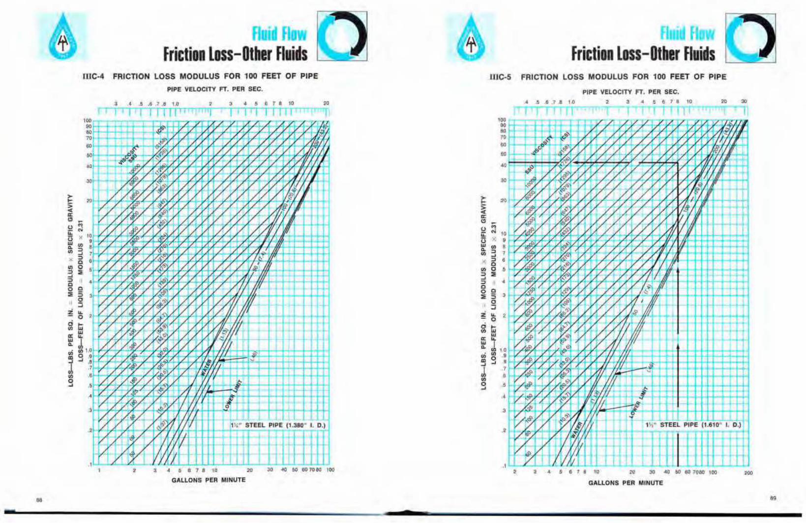
Fluid FlowFriction Loss-Other Fluids
Fluid FlowFriction Loss-Other Fluids
mC-4 FRICTION LOSS MODULUS FOR 100 FEET OF PIPE mc-s FRICTION LOSS MODULUS FOR 100 FEET OF PIPE
PIPE VELOCITY FT. PER SEC.
.4 .5 .6.7.8 1.0 2 3 4 5 6 7 8 10 20 30
fTTTTTTllT セ TTnTfTTrnrrmrrrTl
II I
203 4 5 6 7 8 10
II
2
/
/
/ / V/
/
/
/ /
/
/
//
I'/ I
I II I
/
// !<i
PIPE VELOCITY FT. PER SEC.
P/ /
/
.3 .4 .5 .6.7.8 1.0
/
/ 1/ 1/ // / '"!>"': / / / / fal -
セセN セN
fl." / / V / / V / 1/ /. / セ "1 IIセ
セ '" 'fL/
P'l / ,T, / / 1/ / II
'" 7,:'\" I ,/. '"v / ^iセ / /. V // qV / '/L '(/;1( J!Q:
/VIA セ i/ VI. セ v X V / Vi/,/-b iOGGGGセ " '7 I, / 1& 1/
/ '" .All? / /1 /t/, v'/ VI'V / カャセ / / V V V V / .I.
/ 1/ / f',;/V セ V V 1/1/ /. / i/ 1/ セ/1 < /
/ '/ / / / Nセ/ 1/ /" / / I
/ 1/ / W1/ /. .,,/ / / V / / /. 11.9 /,S>
/ / V
1/ / / 1,< 9'. il セ w G STEEL PIPE (1.380" I. D.)NRエMMイMGM「KvエMKMMᆬMKGセiM「GiヲM」hMエMKKMエMKMイMイMNMMイMMイNLMイゥMセセイtMイャ
100908070
60
50
40
30
>セ 20:>c(II:Cl
セ
U '"i:i: N
0 X 109W Ul
"" 8Ul ::::l
..J 7X ::::l
6Cen 0 5::::l :;:..J::::l II 4C0 C:;: :5 3II 0
::::;
セ LL20
ci セUl W
WII: LLW III.
Ul<Ii Ul 1.0lD 0 .9..J ..J .8
J .7
Ul .60..J .5
.4
v S> V 1,'--t++-++t-+-lH----++I-+II-t-t-t+H-+t-H/ if, 'IT.1 L..L.-"".....J.-L....LLJL.L.U-..L-L.1...L-..L-L.L..l-L-J....-.L.JL.....L..J...I--l......L....L..L..L.....L..l-J....L..J
/ 1//
2
II
3 4 5 6 7 8 10 20 2 3 4 5 6 7 8 10 20 30 40 50 60 7080 100 200
GALLONS PER MINUTE GALLONS PER MINUTE
88 89
2

lui FlowFriction Loss-Other Fluids
•HI
Friction Loss-Other FluidsIIIC-6 FRICTION LOSS MODULUS FOR 100 FEET OF PIPE IIIC-7 FRICTION LOSS MODULUS FOR 100 FEET OF PIPE
20
TTTJTl 20 30
II1
200 300 400 500
6 7 8 10
T r4 532
30 40 50 607080 100
PIPE VELOCITY FT. PER SEC.
20
GALLONS PER MINUTE
N.A'/-l-_Nf+++-+-+-+-2Yi,.."_"_S_TEEL PIPE (2.469" I. D.)
5 6 7 8 10
n
セ
セ
"..,..,30
20
.4 .5.6.7.8 1.0
IT TT
40
.5 QMyT\セセNケ
.4 L...I!:--'" N「G\ャLTMLセOM
10090807060
50
セ
M
'" 10X 9
8 <SUl:::) 7....I:::) 6C0 5:;:II 4
C:::) 3
0:::;u.. 20...
i6'ww "u.. "I
1.0UlUl .90 .8....I
.7
.6
>...:>«II:Cl
UセUw"-Ul
X
Ul:::)....I:::)
Co:;:II
Z
oUl
II:W"-<Iial....I
JUlo....I
30020030 40 50 607080 100
PIPE VELOCITY FT. PER SEC.2 3 4 5 6 7 8 10
I'l TTTTln n.4 .5 .6 .7.8 1.0
TTlI.3
... 90
GALLONS PER MINUTE
91
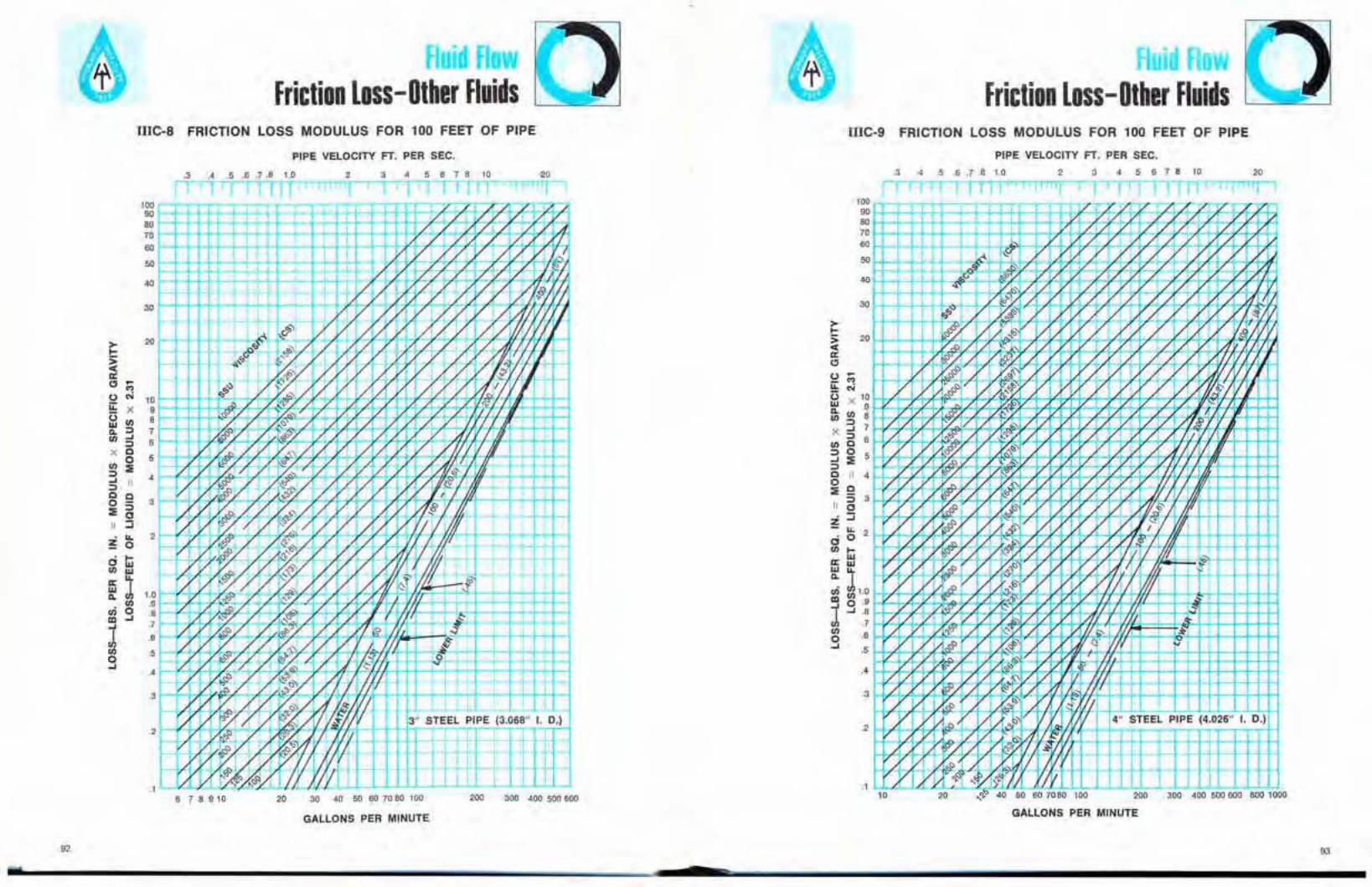
Fluid FlowFriction Loss-Other Fluids
Fluid FlowFriction Loss- Other Fluids
mC-8 FRICTION LOSS MODULUS FOR 100 FEET OF PIPE mC-9 FRICTION LOSS MODULUS FOR 100 FEET OF PIPE
PIPE VELOCITY FT. PER SEC. PIPE VELOCITY FT. PER SEC.
/ 1/ 1/ 1/
q, V/ 1/ Y A1/ I rl
セ
V /, V OiOセ
セ'/ / / /1- - tL/ 'I' !1;l'
Vb.- b4 r-lY-/d VfJ7'; 1/ I'"V / カセ ャWヲOイOセ V-
""'''I 4. V 1/ / iM⦅セ / OQセMGQ..... /セ 4/ /'-t,y-
セ j i0".-- セエT[ b",G
Y W [ M セ 1; '1:111s
I..<WI/+/1/ 1/
/ セ t1 _ セZGTNNTco" 'I' セ セ /1/ 1/ 1/ Iv / / v 101
/ 'FO');
セ<S 1/ it II0.0>
/Mセ
/ / 'I h
<><:s 1/ Iv セ G i I It/'1/ J7, 1/ 1)',,,1/1/ v V / 1/ II II
<><S""
't1/ / 1/ 1/., 1/ 1/ / rv//. lib
,<>'" f/ i!'''r / 4. / I ff«t'&."'7 ;..- セNLoO '4
セ K M O セ { O v v 1/ V7<f? W-I/ セ G I i 1/
.,'1)..1 / 0' V I -yv '(L1f.- rI Iセ\Zウ y I--Y- I
セKカ t7 ,/-9 t?7 セェK、セセュ"-'4- セ IV VZU If-1/ 4' 0 ft カ G ゥ G Q W セ ;0,," (f, 'I ff-/
セ\^ , '-<> ,,,;;--lL - q,./ 4, セ
1/ <>14,7 ",.')1 VI <:> II' セ...,1/ 1/
セ1./,..... / 1/ 1/ -i. '{I セi
セi IYI s>1'_, 1/ IA' '-
セ V セ セ セ セ ケ v i ャ セ H Q,
1/ ,. I
rf- i/
セ M エ ヲ セ At;.... enR L-
1/ 1/ ;/ Ii {I 3" STEEL PIPE (3.068" I. D.)
Nセ 1/ GャNセセ i 1 (III
e7v エ p P セ セ O Q" I-
V
L- a..1/ iGセセセカ / r/1I200 300 400 500 600 800 1000
4 5 6 7 8 10 2032
,'); 40 50 607080 10020
.4 .5 .6.7.8 1.0.3
10
/j'/ /1/ / 4J.Z 1/
/ '1/·/ / 7 /
/1 /
I..... r-8'" . 'I. /1
,,0 セ"" / 1/.. / / 1/1/ /カセ 4/ 1/ / '-1' I I
V I'.,,, .,'" / / 1/ イ セ O
<><:s 1/1/ / VI V1/ 1/ II i/il<:s<> / / 7 / / 1/
セII1I
" / [l;, / / V 1/v <>" セセ 1/ / /
V r/l 1/<S
1/ I; <>" / BBGセ'/ 1/ 1/ V V1/ セ i 1/1/<S
セ '..4 I '1/'I' / 1/ !/ 171/ / 1/ 1/ 1/ /1/ ,
/ 17 セB / '); / / / II IP,,"':/ セB V II VI
セ セ 1/ / I I1/ / 1/ 1/ 17 / 1/1/ rl
/ <>v/ / '" / 'I 1/ III1/ HセBB 1/ i"#.. t;-I '/I
1/ VI ,,"",... 1/ 1/ 1/ 1/1 セ 1/ セGセBI
,- I' . セ / / I
セV-b"/ '1"'1, II lL-
l/ <>" rn IA i I J.17 v 17 1/ V V V rJ II Wi _" 1..-
セ
セ
/ / 1/ 1"/ 1/ / / / 1.17..- ..<; /
,/ r71 b. /'1, セ
<>"Lセ . VI
f/ イ セ セ'"/ 1/
f/ 1-;' 17 f/ "U 1/ !Iセ L -; '" -;
セ I1/ <> r. . rJI
1/ 1/1"" '
1/1/ I.·. 1/ 1/ 4" STEEL PIPE (4.026" I. D.)17 171/ 1..1 iOセ
:;»"/ / ., . f/ i セ II1/ <> r7 II
6/y 1) f/ " -II..<:S セ <P' '(I
.5
20
.2
.3
40
.4
30
10090807060
50
.1
>セ
セa::Cl
u c:;i::L C'i() X 10W 9ll; Ul 8
:3 7x::::l 6
Ul C::::l 0 5.... :;:::::lC II 4
セ c:5 3
110z ::::i
... 2ci°Ul セ
a:: ttlw ...Q. I<Ii セ 1.0セ 0,9J ....8vr .7Ulo .6....
20
JTTTTTI
200 300 400 500 600
2 _--..::.3_,4-r5;-6;.-:7n8,..:.10rrT"T
-rr
30 40 50607080100206 7 8 910
.3 .4 .5 .6 .7.8 1.0
rTITTTTTTT
.2
4
.3
.4
20
.1
2
3
109876
5
40
30
1.0.9.8.7
.6
.5
100908070
60
50
>セ
:>«a::Cl セ
'"U NiL x()
UlWQ. ::::lUl ....
::::lX C
0Ul :;:::::l.... II::::lC C0 :5:;: 0II ::;
セIL0
ci セwUl wa:: IL
W JQ.Ul
<Ii 0al ........JUl0....
GALLONS PER MINUTE GALLONS PER MINUTE
92 93
w 7
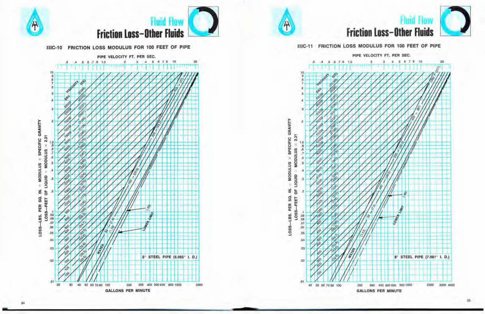
Fluid FlowFriction Loss-Other Fluids
Fluid FlowFriction Loss- Other Fluids
IIIC-10 FRICTION LOSS MODULUS FOR 100 FEET OF PIPE IIIC-11 FRICTION LOSS MODULUS FOR 100 FEET OF PIPE
-
セ
2000 3000 4000
4 5 6 7 8 10
r r32
'//
J
200 300 400 500600 8001000
GALLONS PER MINUTE
PIPE VELOCITY FT. PER SEC.
セ / セN /f / セ f/ 8" STEEL PIPE (7.981" I. D.)
40 50 60 70 80 100
.3 .4 .5 .6 .7.8 1.0
rTTTTT' 11"T '1
.05
.04V
.03
.02I-Q ;,'e / / セOセaKMKMiMKMKKMKMKMhMhM t-4I ++-+-I-+-+
'l LAD" Kセセセセ,,<:> iii M O エ O H M M ᆬ O M ャ M M i K M M K M M K M K M ャ セ N ⦅ M K M K M K K K/ / 11
.01 lNNNlMBGjiMNNilMlljlAMuセNlljNNNNNjNNNNNiNMNNNNlNNNNlNNNllNNNiNNNlMNNlMNliNMiNNNjlNNNM
10987
6
5
4
3
21/
1/
セ
'"N
2000200 300 400 500 600 800 1000
GALLONS PER MINUTE
PIPE VELOCITY FT. PER SEC..3 .4 .5 .6 .7.6 1.0 2 3 4 5 6 7 8 10 20
fTTTT'T
•94
! .
95

Fluid FlowFriction Loss-Other Fluids
Fluid FlowFriction Loss-Other Fluids
IIIC-12 FRICTION LOSS MODULUS FOR 100 FEET OF PIPE IIIC-13 FRICTION LOSS MODULUS FOR 100 FEET OF PIPE
PIPE VELOCITY FT. PER SEC. PIPE VELOCITY FT. PER SEC.
2000 (433)
20
2000 3000 4000 6000 8000
3 4 5 6 7 8 102
200 300 400 500600 8001000
GALLONS PER MINUTE
.3 .4 .5 .6.7.8 1.0
80 100
i;,,...--
/セ セ vro " 1/ V V 1/ 1/ 1.1
roG <,; I /,,,セ G ゥ 1/ V V V V / / V IV.Ii>CS / ol>VI/ VV V 1/ / V V セ 'Jセセ LNLセ / '7 セ r1
v セセ V,,- nl', / / / V V v/ セB / セO / / v / v V / IA
/ セB / ",-<> / V IV / VJ i/.V セcs " /"., V V V vV v 1/ IiI fI'"v V / m II
1/ セ G IV " V V V V f/ rl/ vlセ / 4-'Vv V 1/ / 1/ J 1, セ iOセ
V セB 0, V/ /v V V 11'", il 1.4'"" 'I II!
1.1 V 'J ""/ V IA' IIJ II v'/ Vi:! IV' '/ 1/ V V v' I Ii
v " / BGセL vv V v V 'I Vi'I/. J/ 1/
.I ',,' 1/ '" Ii1.1 V v II VII
/ V .. V 'V IA. II VI1.1 .I 1.1 / セ Vj,I Vv W. 'I IIII v セ v,:" !.Iy v Vl./ V fI 0
v CS n'l/ V '?-V P V セj V v 'L lL II セ
/ I/.' / セカカ / (;I,/11-'" セ\sG '''v f1, セM Iff
iL'- A IL
OJ '"'" V 'II 1/.
1/ IV I'-V v IV 1/ セ
V / 'lo"'Vj,l II I. -Ii;1/ / IZ
<:J I'" 1/,; II
IV IV ャ o セ G 'IV Iv 1/ セ G | [11/V 1/
/ FoCS/ rIll 'I 2" STEEL PIPE (11.938" I. D.)
V セ I.1/ 1.1 (J 'iV1/ 1/ I- '/ セ イ [
v W II
.02
.03
.04
.01
3
4
10987
6
5
> 2l-:>c(a:Cl セo ..,i:L N 1.0o X .9w til .8Co.til :3 .7X ::::) .6
Ctil 0 .5::::> :;;:5 II .4Co 9 3:;; ::::> •
oII :::iZ "- .2
oo l-til W
Wa: "-セ l .1en til .09ID g .08"I .07til .06tilo .05...
7000
204 5 6 7 8 10
GALLONS PER MINUTE
1/ il
.3 .4 .5 .6.7.8 1.0
l/iOl' II 1/'[11/ セセャ J II r/
.01 ャNNZZiセNNオiNNNNNNゥlNlャllNャlllllNNlNjMlNNljlNNMlNjMNlNNNlNNャMMGMQNBBBGNNlNNjN⦅GMMlNNNNjBBBNNjNNNjMMGQNNNj
70 80 100 200 300 400 500600 800 1000 2000 3000 4000
9697
Fluid FlowFriction Loss-Other Fluids
IIIC-14 INSTALLATION FOR EXAMPLE No.4 IIIC-15
Fluid FlowFriction Loss- Other Fluids
TABLE 34-FRICTION LOSS FOR VISCOUS LIQUIDSLoss in Pounds Per Square Inch Per 100 Feet
of New Schedule 40 Steel Pipe Based on Specific Gravity of 1.00
MANIFOLD PRESSURE = 250 psi
MOTOR DRIVEN
20'
PipeVISCOSITY-SAYBOLT SECONDS UNIVERSAL
GPM Size100 200 300 400 500 1000 1500 2000 2500 3000 4000 5000 6000 7000 8000 9000 10,000 15,000
'" 11.2 23.6 35.3 47.1 59 118 177 236 294 353 471 589 706 824 942 - - -3 " 3.7 7.6 11.5 15.3 19.1 38.2 57 76 96 115 153 191 229 268 306 344 382 573
1 1.4 2.9 4.4 5.8 7.3 14.5 21.8 29.1 36.3 43.6 58 73 87 101 116 131 145 218
¥, 6.1 12.7 19.1 25.5 31.9 64 96 127 159 191 255 319 382 446 510 573 637 956
5 1 2.3 4.9 7.3 9.7 12.1 24.2 36.3 48.5 51 73 97 121 145 170 194 218 242 363
lV, 0.77 1.6 2.4 3.3 4.1 8.1 12.2 16.2 20.3 24.3 32.5 40.6 48.7 57 65 73 81 122
,!" 8.5 17.9 26.8 35.7 44.6 89 134 178 223 268 357 446 535 624 713 803 892 -7 1 3.2 6.8 10.2 13.6 17 33.9 51 68 85 102 136 170 203 237 271 305 339 509
Ilf4 1.1 2.3 3.4 4.5 5.7 11.4 17 22.7 28.4 34.1 45.4 57 68 80 91 102 114 170
1 4.9 9.7 14.5 19.4 24.2 48.5 73 97 121 145 194 242 291 339 388 436 485 727
10 IV, 1.6 3.3 4.9 6.5 8.1 16.2 24.3 32.5 40.6 48.7 65 81 97 114 130 146 162 243
'''' 0.84 1.8 2.6 3.5 4.4 8.3 13.1 17.5 21.9 26.3 35 43.8 53 51 70 79 88 131
1 11 14.5 21.8 29.1 36.3 73 109 145 182 218 291 363 436 509 581 654 727 -15 11/4 2.8 4.9 7.3 9.7 12.2 24.3 36.5 48.7 51 73 97 122 146 170 195 219 243 365
1)1 1.3 2.6 3.9 5.3 6.6 13.1 19.7 26.3 32.8 39.4 53 66 79 92 105 118 131 197
1 18 18 29.1 38.8 48.5 97 145 194 242 291 388 485 581 678 775 872 - -20 "'" 4.9 6.4 9.7 13 16.2 32.5 48.7 65 81 97 130 162 195 227 260 292 325 487
IV, 2.3 3.5 5.3 7 8.8 17.5 26.3 35 43.8 53 70 88 105 123 140 158 175 263
2 0.64 1.3 1.9 2.6 3.2 6.4 9.6 12.9 16.1 19.3 25.7 32.1 38.5 45 51 58 64 96
'''' 3.5 4.4 6.6 8.8 11 21.9 32.8 43.8 55 66 88 110 131 153 176 197 219 328
25 2 1 1.6 2.4 3.2 4 8 12.1 16.1 20.1 24.1 32.1 40.2 48.2 56 64 72 80 121
2'" 0.4 0.79 1.2 1.6 2 4 5.9 7.' 9.9 11,8 15.8 19.7 23.7 27.6 31.6 35.5 39.5 59
'''' 5 5.3 7.9 10.5 13.1 26.3 39.4 53 66 79 105 131 158 184 210 237 263 394
30 2 1.4 1.9 2.9 3.9 4.8 9.6 14.5 19.3 24.1 28.9 38.5 48.2 58 67 77 87 96 145
2V> 0.6 0.95 1.4 1.9 2.4 4.7 7.1 9.5 11.8 14.2 19 23.7 28.4 33.2 37.9 42.6 47.4 71
'''' 8.5 9 10.5 14 17.5 35 53 70 88 105 140 175 210 245 280 315 350 526
40 2 2.5 2.5 3.9 5.1 6.4 12.9 19.3 25.7 32.1 38.5 51 64 77 90 103 116 129 193
2'" 1.1 1.3 1.9 2.5 3.2 6.3 95 12.6 15.8 19 25.3 31.6 37.9 44.2 51 57 63 95
IX 12.5 14 14.0 17.5 21.9 43.8 66 88 110 131 175 219 263 307 350 394 438 657
50 2 3.7 4 4.8 6.4 8 16.1 24.1 32.1 40.2 48.2 64 80 96 112 129 145 161 241
2'" 1.6 1.7 2.4 3.2 4 7.9 11.8 15.8 19.7 23.7 31.6 39.5 47.4 55 63 71 79 118
2 5 5.8 5.8 7.7 9.6 19.3 28.9 38.5 48.2 58 77 96 116 135 154 173 193 289
60 2V> 2.2 2.4 2.8 3.8 4.7 9.5 14.2 19 23.7 28.4 37.9 47.4 57 66 76 85 95 142
3 0.8 0.8 1.2 1.6 2 4 6 8 9.9 11.9 15.9 19.9 23.9 27.9 31.8 35.8 39.8 60
2", 2.8 3.2 3.4 4.4 5.5 11.1 16.6 22.1 27.6 33.2 44.2 55 66 77 88 100 III 166
7D 3 1 1.1 1.4 1.9 2.3 4.6 7 9.3 11.6 13.9 18.6 23.2 27.8 32.5 37.1 41.7 46.4 70
4 0.27 0.31 0.47 0.63 0.73 1.6 2.4 3.1 3.9 4.7 6.3 7.8 9.4 11 12.5 14.1 15.6 23.5
2'" 3.6 4.2 4.2 5.1 6.3 12.6 19 25.3 31.6 37.9 51 63 76 88 101 114 126 190
80 3 1.3 1.4 1.6 2.1 2.7 5.3 8 10.6 13.3 15,9 21.2 26.5 31.8 37.1 42.4 47.7 53 80
4 0.36 0.36 0.54 0.72 0.89 1.8 2.7 3.6 4.5 5.4 7.2 8.9 10.7 12.5 14.3 16.1 17.9 26.8
2'" 5.3 6.1 6.4 6.4 8 15.8 23.7 31.6 39.5 47.4 63 79 95 111 127 142 158 237
100 3 1.9 2.2 2.2 2.7 3.3 6.6 9.9 13.3 16.6 19.9 26.5 33.1 39.8 46.4 53 60 66 99
4 0.52 0.57 0.67 0.89 1.1 2.2 3.4 4.5 5.6 6.7 8.9 11.2 13.4 15.6 17.9 20.1 22.3 33.5
.. TURBULENT.. •FLOW
LAMINAR FLOW --NOTE: For a liquid having a specific gravity other than 1.00 multiply the value from the table by the specific gravity of that liquid.
For commercial installations, it is recommended that 15% be added to the above values. No allowance for aging of pipe isincluded.
7

Fluid FlowFriction Loss- Other Fluids
Fluid FlowFriction Loss-Other Fluids
IIIC-15 TABLE 34 (Continued)-FRICTION LOSS FOR VISCOUS LIQUIDSLoss in Pounds Per Square Inch Per 100Feet
of New Schedule 40 Steel Pipe Based on Specific Gravity of 1.00
IIIC-15 TABLE 34 (Continued)-FRICTION LOSS FOR VISCOUS LIQUIDSLoss in Pounds Per Square Inch Per 100Feet
of New Schedule 40 Steel Pipe Based on Specific Gravity of 1.00
F'
Pipl! VISCOSITY-SAYBOLT SECONDS UNIVERSALGPM Sfll! 100 200 300 400 500 1000 1500 2000 2S00 3000 4000 5000 6000 7000 1000 9000 10,000 15,000
3 2.7 3.1 3.2 3.2 4 8 11.9 15.9 19.9 23.9 31.8 39.8 47.7 56 64 72 80 119120 4 0.73 0.81 0.81 1.1 1.3 2.7 4 5.4 6.7 8 10.7 13.4 16.1 18.8 21.4 24.1 26.8 40.2
6 .098 0.11 0.16 0.21 0.26 0.52 0.78 1.0 1.3 1.6 2.1 2.6 3.1 3.6 4.2 4.7 5.2 7.8
3 3.4 4 4.3 4.3 4.6 '.3 13.9 18.6 23.2 27.8 37.1 46.4 56 65 74 84 93 139140 4 0.95 1.1 1.1 1.3 1.6 3.1 4.7 6.3 7.8 '.4 12.5 15.6 18.8 21.9 25 28.2 31.3 46.9
6 0.13 0.15 0.18 0.24 0.30 0.61 0.91 1.2 1.5 1.8 2.4 3.0 3.6 4.2 4.' 5.5 6.1 '.1
3 4.4 5 5.7 5.7 5.7 10.6 15.9 21.2 26.5 31.8 42.4 53 64 74 85 95 106 159160 4 1.2 1.4 1.4 1.4 1.8 3.6 5.4 7.2 8.' 10.7 14.3 17.9 21.5 25 28.6 32.2 35.7 54
6 0.17 0.18 0.21 0.28 0.35 0.69 1.0 1.4 1.7 2.1 2.8 3.5 4.2 4.' 5.5 6.2 6.' 10.4
3 5.3 6.3 7 7 7 11.9 17.9 23.9 29.8 35.8 47.7 60 72 84 95 107 119 179180 4 1.5 1.8 1.8 1.8 2 4 6 8 10.1 12.1 16.1 20.1 24.1 28.1 32.2 36.2 40.2 60
6 0.2 0.24 0.24 0.31 0.39 0.78 1.2 1.6 2 2.3 3.1 3.' 4.7 5.5 6.2 7 7.8 11.7
3 6.5 7.7 8.8 8.8 8.8 13.3 19.9 26.5 33.1 39.8 53 66 80 93 106 119 133 199200 4 1.8 2.2 2.2 2.2 2.2 4.5 6.7 8.' 11.2 13.4 17.9 22.3 26.8 31.3 35.7 40.2 44.7 67
6 0.25 0.3 0.3 0.35 0.43 0.87 1.3 1.7 2.2 2.6 3.5 4.3 5.2 6.1 6.' 7.8 8.7 13
4 2.6 3.2 3.5 3.5 3.5 5.6 8.' 11.2 14 16.8 22.3 27.9 33.5 39.1 44.7 50 56 84250 6 0.36 0.43 0.45 0.45 0.54 1.1 1.6 2.2 2.7 3.3 4.3 5.4 6.5 7.6 8.7 '.8 10.8 16.3
8 .095 0.12 0.12 0.15 0.18 0.36 0.54 0.72 D.' 1.1 1.5 1.8 2.2 2.5 2.' 3.3 3.6 5.4
4 3.7 4.3 5 5 5 6.7 10.1 13.4 16.8 20.1 26.8 33.5 40.2 47 54 60 67 101300 6 0.5 0.6 0.65 0.65 0.65 1.3 2 2.6 3.3 3.9 5.2 6.5 7.8 9.1 10.4 11.7 13 19.5
8 0.13 0.17 0.17 0.18 0.22 0.43 0.65 0.87 1.1 1.3 1.7 2.2 2.6 3 3.5 3.' 4.3 6.5
6 0.82 1 1.1 1.2 1.2 1.7 2.6 3.5 4.3 5.2 6.' 8.7 10.4 12.1 13.9 15.6 17.3 26400 8 0.23 0.27 0.29 0.29 0.29 0.58 0.87 1.2 1.5 1.7 2.3 2.' 3.5 4.1 '.6 5.2 5.8 8.7
10 D." 0.09 0.1 0.1 0.12 0.23 0.35 0.47 0.58 0.7 0.93 1.2 1.4 1.6 I., 2.1 2.3 3.5
6 1.2 1.5 1.6 1.8 1.8 2.2 3.2 4.3 5.4 6.5 8.7 10.8 13 15.2 17.3 19.5 21.7 32.5500 8 0.33 0.39 0.44 0.47 0.47 0.72 1.1 1.5 1.8 2.2 2.' 3.6 4.3 5.1 5.8 6.5 7.2 10.8
10 0.11 0.14 0.15 0.15 0.15 0.29 0.44 O.sa 0.73 0.87 1.2 1.5 1.8 2 2.3 2.6 2.' 4.4
6 1.8 2.2 2.3 2.4 2.6 2.7 3.' 5.2 6.5 7.8 10.4 13 16 18.2 20.8 23.4 26 39ODD 8 0.47 0.57 0.62 0.67 0.67 0.87 1.3 1.7 2.2 2.6 3.5 4.3 5.2 6.1 6.' 7.8 8.7 13
10 0.16 0.18 0.2 0.22 0.22 0.35 0.52 0.7 0.87 1.1 1.4 1.8 2.1 2.4 2.8 3.3 3.5 5.2
6 2.3 2.7 3 3.2 3.5 3.6 4.6 6.1 7.6 '.1 12.1 15.2 18.4 21.2 24.3 27.3 30.3 45.5
"Xl 8 0.6 0.74 0.82 0.89 0.93 1 1.5 2 2.5 3 4.1 5.1 6.1 7.1 8.1 9.1 10.1 15.210 0.2 0.25 0.27 0.3 0.3 0.41 0.61 0.82 1 1.2 1.6 2 2.4 2.' 3.3 3.7 4.1 6.1
6 2.8 3.5 3.7 4 4.2 4.8 5.2 6.' 8.7 10.4 13.9 17.3 20.8 24.3 27.7 31.2 34.7 52..0 8 0.78 0.94 1 1.1 1.2 1.2 1.7 2.3 2.' 3.5 4.6 5.8 6.' 8.1 '.3 10.4 11.6 17.3
10 0.26 0.3 0.34 0.38 0.4 0.47 0.7 0.92 1.2 1.4 I.' 2.3 2.8 3.3 3.7 4.2 4.7 7
6 3.5 4.3 4.6 5.0 5.2 6 6 7.8 '.8 11.7 15.6 19.5 23.4 27.3 31.2 35.1 39 58.5900 8 0.95 1.1 1.3 1.4 1.5 1.5 2 2.6 3.3 3.' 5.2 6.5 7.8 '.1 10.4 11.7 13 19.5
10 0.32 0.37 0.43 0.46 0.5 0.52 0.79 1.1 1.3 1.6 2.1 2.6 3.1 3.7 4.2 4.7 5.2 7.'
8 1.1 1.4 1.5 1.6 1.8 I.' 2.2 2.' 3.6 4.3 5.8 7.2 8.7 10.1 11.6 13 14.5 21.71000 10 0.38 0.45 0.5 0.55 0.6 0.6 0.87 1.2 1.5 1.8 2.3 2.' 3.5 '.1 4.7 5.2 5.8 8.7
12 0.17 0.2 0.22 0.24 0.25 0.29 0.43 0.58 0.72 0.87 1.2 1.5 1.7 2 2.3 2.6 2.' 4.3
TURBULENTM M M M Z N N N ] N N Z f L [ [ Z l Z N N Z o Z N Z w ] セ N M .....-------LAMINAR FLOW--------..セ セ
NOTE: For a liquid having a specific gravity other than 1.00 multiply the value from the table by the specific gravity of that liquid.For commercial installations, it is recommended that 15% be added to the above values. No allowance for aging of pipe isincluded.
100
7
PipeVISCOSITY-SAYBOLT SECONDS UNIVERSAL
GPM Size20,000 25,000 30,000 40,000 150,000 60,000 70,000 I 80,000 I 90,000 100,000 125,000 150,000 175,000 200,000 SOO,OOO
2 19.3 24.1 28.9 38.5 48.2 sa 67 77 87 '6 120 145 16' 193 482
3 2y" '.5 11.8 14.2 19 23.7 28.4 33.2 37.9 42.6 47.4 59 71 83 95 237
3 4 5 6 8 9.9 11.9 13.9 15.9 17.9 19.9 24.9 29.8 34.8 39.8 99
2 32 40 48.2 64 80 '6 112 129 145 161 201 241 281 321 803, 2"" 15.8 19.7 23.7 31.6 39.5 47.4 55 63 71 79 99 118 138 lsa 395
3 6.6 8.3 ,., 13.3 16.6 ,., 23.2 26.5 29.8 33 41.4 49.7 58 66 166
2 45 56 67 90 112 135 157 180 202 225 281 337 393 450 -7 2"" 22.1 27.6 33.2 44.2 59 66 77 88 100 III 138 166 1'4 22l 553
3 '.3 11.6 13.9 18.6 23.2 27.8 32.5 37.1 41.7 46.4 58 70 81 93 232
2'" 31.6 39.5 47.4 63 79 95 III 126 142 158 197 237 276 316 790
10 3 13.3 16.6 19.9 26.5 33.1 39.8 46.4 53 60 66 83 99 116 133 331
4 4.5 5.6 6.7 8.' 11.2 13.4 15.6 17.9 20.1 22.3 27.9 33.5 39.1 44.7 112
m 47.4 59 71 95 118 142 166 190 213 237 296 355 415 474 -
" 3 19.9 24.9 29.8 39.8 49.7 60 70 80 89 99 124 149 174 199 497
4 6.7 8.4 10.1 13.4 16.8 20.1 23.5 26.8 30.2 33.5 41.9 50 59 67 168
3 26.5 33.1 39.8 53 66 80 93 106 119 133 166 199 232 265 663
20 4 8.' 11.2 13.4 17.9 22.3 26.8 31.3 35.7 40.2 44.7 56 67 78 89 223
6 1.7 2.2 2.6 3.5 4.3 5.2 6.1 6.' 7.8 8.7 10.8 13 15.2 17.3 43.3
3 33.1 41.4 49.7 66 83 99 116 133 149 166 207 249 290 331 828
25 4 11.2 14 16.8 22.3 27.9 33.5 39.1 44.7 50 56 70 84 98 112 279
6 2.2 2.7 3.3 4.3 5.4 6.5 7.6 8.7 '.8 10.8 13.5 16.3 19 21.7 54
3 39.8 49.7 60 80 99 119 139 159 179 199 249 298 348 398 -30 4 13.4 16.8 20.1 26.8 33.5 40.2 46.9 54 60 67 84 101 117 134 335
6 2.6 3.3 3.' 5.2 6.5 7.8 '.1 IDA 11.7 13 16.3 19.5 22.7 26 65
3 53 66 80 106 133 160 186 212 239 265 331 398 464 532 -40 4 17.9 22.3 26.8 35.7 44.7 54 63 72 80 89 112 134 156 179 447
6 3.5 4.3 5.2 6.' 8.7 IDA 12.1 13.9 15.6 17.3 21.7 26 30.3 34.7 87
4 22.3 27.9 33.5 44.7 56 67 78 89 101 112 140 168 196 223 559
50 6 4.3 5.4 6.5 8.7 10.8 13 15.2 17.3 19.5 21.7 27.1 32.5 37.9 43.3 108
8 1.5 1.8 2.7 2.' 3.6 4.3 5.1 5.8 6.5 7.2 , 10.8 12.6 14.5 36.1
4 26.8 33.5 40.2 54 67 80 94 107 121 134 168 201 235 268 670
60 6 5.2 6.5 7.8 10.4 13 16 18.2 20.8 23.4 26 32.5 39 45.5 52 130
8 1.7 2.2 2.6 3.5 4.3 5.2 6.1 6.' 7.8 8.7 10.8 13 15.2 17.3 43.4
4 31.3 39.1 46.9 63 78 94 110 125 141 156 196 235 274 313 782
70 6 6.1 7.6 '.1 12.1 15.2 18.4 21.2 24.3 27.3 30.3 37.9 45.5 53 61 152
8 2 2.5 3 4.1 5.1 6.1 7.1 8.1 '.1 10.1 12.6 15.2 17.7 20.2 51
6 6.' 8.7 10.4 13.9 17.3 20.8 24.3 27.7 31.2 34.7 43.3 52 61 6' 173
80 8 2.3 2.' 3.5 4.6 5.8 6.' 8.1 '.3 IDA 11.6 14.5 17.3 20.2 23.1 58
10 0.93 1.2 1.4 I.' 2.3 2.8 3.3 3.7 4.2 4.7 5.8 7 8.2 '.3 23.3
6 7.8 '.8 11.7 15.6 19.5 23.4 27.3 31.2 35.1 39 48.7 59 68 78 195
90 8 2.6 3.3 3.' 5.2 6.5 7.8 '.1 IDA 11.7 13 16.3 19.5 22.8 26 65
10 Ll 1.3 1.6 2.1 2.6 3.1 3.7 4.2 4.7 5.2 6.6 7.' '.2 10.5 26.2
6 8.7 10.8 13 17.3 21.7 26 30.3 34.7 39 43.3 54 65 76 87 217
100 8 2.' 3.6 4.3 5.8 7.2 8.7 10.1 11.6 13 14.5 18.1 21.7 25.3 28.9 72
10 1.2 1.5 1.8 2.3 2.' 3.5 4.2 4.7 5.2 5.8 7.3 8.7 10.2 11.6 29.1
LAMINAR FLOW
NOTE: For a liquid having a specific gravity other than 1.00 multiply the value from the table by the specific gravity of that liquId.For commercial installations, it is recommended that 15% be added to the above values. No allowance for aging of pipe isincluded.
101
Fluid FlowFriction Loss- Other Fluids
Fluid FlowFriction Loss of Nozzles
IIID-1 -THEORETICAL DISCHARGE OF NOZZLES IN U.S. GALLONS PER MINUTE
TABLE 35
HeadVeloc'y
Diameter of Nozzle in InchesofDisch.
PSIG Feet Feet l{. Yo li'. y, % Y, % % Yo 1 1X 1}4 1%per Sec.
10 23.1 38.6 0.37 1.48 3.32 5.91 13.3 23.6 36.9 53 72 94 120 148 17915 34.6 47.25 0.45 1.81 4.06 7.24 16.3 28.9 45.2 65 88 116 147 181 21920 46.2 54.55 0.52 2.09 4.69 8.35 19.8 33.4 52.2 75 102 134 169 209 25325 57.7 61.0 0.58 2.34 5.25 9.34 21.0 37.3 58.3 84 114 149 189 234 283
30 69.3 66.85 0.64 2.56 5.75 10.2 23.0 40.9 63.9 92 125 164 207 256 30935 80.8 72.2 0.69 2.77 6.21 11,1 24.8 44.2 69.0 99 135 177 224 277 33440 92.4 77.2 0.74 2.96 6.64 11.8 26.6 47.3 73.8 106 145 189 239 296 35745 103.9 81.8 0.78 3.13 7.03 12.5 28.2 50.1 78.2 113 153 200 253 313 379
50 115.5 86.25 0.83 3.30 7.41 13.2 29.7 52.8 82.5 119 162 211 267 330 39955 127.0 90.5 0.87 3.46 7.77 13.8 31.1 55.3 86.4 125 169 221 280 346 41860 138.6 94.5 0.90 3.62 8.12 14.5 32.5 57.8 90.4 130 177 231 293 362 43865 150.1 98.3 0.94 3.77 8.45 15.1 33.8 60.2 94.0 136 184 241 305 376 455
70 161.7 102.1 0.98 3.91 8.78 15.7 35.2 62.5 97.7 141 191 250 317 391 47375 173.2 105.7 1.01 4.05 9.08 16.2 36.4 64.7 101.0 146 198 259 327 404 48980 184.8 109.1 1.05 4.18 9.39 16.7 37.6 66.8 104.0 150 205 267 338 418 50585 196.3 112.5 1.08 4.31 9.67 17.3 38.8 68.9 108.0 155 211 276 349 431 521
90 207.9 115.8 1.11 4.43 9.95 17.7 39.9 70.8 111.0 160 217 284 359 443 53695 219.4 119.0 1.14 4.56 10.2 18.2 41.0 72.8 114.0 164 223 292 369 456 551
100 230.9 122.0 1.17 4.67 10.5 18.7 42.1 74.7 117.0 168 229 299 378 467 565105 242.4 125.0 1.20 4.79 10.8 19.2 43.1 76.5 120.0 172 234 306 388 479 579
110 254.0 128.0 1.23 4.90 11.0 19.6 44.1 78.4 122.0 176 240 314 397 490 593115 265.5 130.9 1.25 5.01 11.2 20.0 45.1 80.1 125.0 180 245 320 406 501 606120 277.1 133.7 1.28 5.12 11.5 20.5 46.0 81.8 128.0 184 251 327 414 512 619125 288.6 136.4 1.31 5.22 11.7 20.9 47.0 83.5 130.0 188 256 334 423 522 632
130 300.2 139.1 1.33 5.33 12.0 21.3 48.0 85.2 133.0 192 261 341 432 533 645135 311.7 141.8 1.36 5.43 12.2 21.7 48.9 86.7 136.0 195 266 347 439 543 656140 323.3 144.3 1.38 5.53 12.4 22.1 49.8 88.4 138.0 199 271 354 448 553 668145 334.8 146.9 1.41 5.62 12.6 22.5 50.6 89.9 140.0 202 275 360 455 562 680
150 346.4 149.5 1.43 5.72 12.9 22.9 51.6 91.5 143.0 206 280 366 463 572 692175 404.1 161.4 1.55 6.18 13.9 24.7 55.6 98.8 154.0 222 302 395 500 618 747200 461.9 172.6 1.65 6.61 14.8 26.4 59.5 106.0 165.0 238 323 423 535 660 799250 577.4 193.0 1.85 7.39 16.6 29.6 66.5 118.0 185.0 266 362 473 598 739 894300 692.8 211.2 2.02 8.08 18.2 32.4 72.8 129.0 202.0 291 396 517 655 808 977
IIIC-15 TABLE 34 (Concluded)-FRICTION LOSS FOR VISCOUS LIQUIDSLoss in Pounds Per Square Inch Per 100 Feet
of New Schedule 40 Steel Pipe Based on Specific Gravity of 1.00
PipeVISCOSITY-SAYBOLT SECONDS UNIVERSAL
CPM Size20,000 25,000 30,000 40,000 50,000 60,000 70,000 80,000 90,000 100,000 125,000 150,000 175,000200,000 500,000
6 10.4 13 15.6 20.8 26 31.2 36.4 41.6 46.8 52 65 78 91 104 260
120 8 3.5 4.3 5.2 6.' 8.7 10.4 12.1 13.9 15.6 17.3 21.7 26 30.4 34.7 87
10 1.4 1.8 2.1 2.8 3.5 4.2 4.' 5.6 6.3 7 8.7 10.5 12.2 14 34.9
6 12.1 15.2 18.2 24.3 30.3 36.4 42.5 48.5 55 51 76 91 106 121 303
140 8 4 5.1 6.1 8.1 10.1 12.1 14.2 16.2 18.2 20.2 25.3 30.4 35.4 40.5 101
10 1.7 2 2.4 3.3 4.1 4.9 5.7 6.5 7.3 8.1 10.2 12.2 14.3 16.3 40.7
6 13.9 17.3 20.8 27.7 34.7 41.6 48.5 56 62 69 87 104 121 139 347
160 8 4.6 5.8 6.' '.3 11.6 13.8 16.2 18.5 20.8 23.1 28.9 34.7 40.5 46.2 116
10 1.9 2.3 2.8 3.7 4.7 5.6 6.5 7.5 8.4 9.3 11.6 14 16.3 18.6 46.6
6 15.6 19.5 23.4 31.2 39 46.8 55 62 70 78 98 117 137 156 390
180 8 5.2 6.5 7.8 10.4 13 15.6 18.2 20.8 23.4 26 32.5 39 45.5 52 130
10 2.1 2.6 3.1 4.2 5.2 6.3 7.3 8.4 '.4 10.5 13.1 15.7 18.3 2l 52
8 5.8 7,2 8.7 11.6 14.5 17.3 20.2 23.1 26 28.9 36.1 43.4 51 58 145
200 10 2.3 2.' 3.5 4.7 5.8 7 8.2 '.3 10.5 11.6 14.6 17.5 20.4 23.3 58
12 1.2 1.5 1.7 2.3 2.' 3.5 4.1 4.6 5.2 5.8 7.2 8.7 10.1 11.6 28.9
8 7.2 9 10.8 14.5 18.1 21.7 25.3 28.9 32.5 36.1 45.2 54 63 72 181
250 10 2.' 3.6 4.4 5.8 7.3 8.7 10.2 11.6 13.1 14.6 18.2 21.8 25.5 29.1 73
12 1.5 1.8 2.2 2.' 3.6 4.3 5.1 5.8 6.5 7.2 , 10.9 12.7 14.5 36.2
8 8.7 10.8 13 17.3 21.7 26 30.4 34.7 39 43.4 54 65 76 87 217
300 10 3.5 4.4 5.2 7 8.7 10.5 12.2 14 15.7 17.5 21.8 26.2 30.6 34.9 87
12 1.7 2.2 2.6 3.5 4.3 5.2 6.1 7 7.8 8.7 10.9 13 15.2 17.4 43.4
8 11.6 14.5 17.3 23 28.9 34.7 40.5 46.2 52 58 72 87 101 116 289
400 10 4.7 5.8 7 9.3 11.6 14 16.3 18.6 2l 23.3 29.6 34.9 40.7 46.6 116
12 2.3 2.' 3.5 4.6 5.8 7 8.1 9.3 10.4 11.6 14.5 17.4 20.3 23.2 58
8 14.5 18.1 21.7 28.9 36.1 43.4 51 58 65 72 '0 108 126 145 361
500 10 5.8 7.3 8.7 11.6 14.6 17.5 2004 23.3 26.2 29.1 36.4 43.7 51 58 146
12 2.' 3.6 4.3 5.' 7.2 8.7 10.1 11.6 13 14.5 18.1 21.7 25.3 28.9 72
8 17.3 21.7 26 34.7 43.4 52 51 69 78 87 lOB 130 152 173 434
600 10 7 8.7 10.5 14 17.5 2l 24.4 27.9 31.4 34.9 43.7 52 61 70 175
12 3.5 4.3 5.2 7 8.7 10.4 12.2 13.9 15.6 17.4 21.7 26.1 30.4 34.7 87
8 20.2 25.3 30.3 40.5 51 51 71 81 91 101 126 152 177 202 506
700 10 8.2 10.2 12.2 16.3 20.4 24.4 28.5 32.6 36.7 40.7 51 51 71 82 204
12 4.1 5.1 6.1 8.1 10.1 12.2 14.2 16.2 18.2 20.3 25.3 30.4 35.5 40.5 101
8 23.1 28.9 34.7 46.2 58 69 81 93 104 116 145 173 202 231 578
BOO 10 '.3 11.6 14 18.6 23.3 27.9 32.6 37.3 41.9 46.6 58 70 82 93 233
12 4.6 5.8 7 '.3 11.6 13.9 16.2 18.5 20.8 23.1 28.9 34.7 40.5 46.3 116
8 26 32.5 39 52 65 78 91 104 117 130 163 195 228 260 650
900 10 10.5 13.1 15.7 2l 26.2 31.4 36.7 41.9 47.1 52 66 79 92 lOS 262
12 5.2 6.5 7.8 10.4 13 15.6 18.2 20.8 23.4 26.1 32.6 39.1 45.6 52 130
8 28.9 36.1 43.4 58 72 87 101 116 130 145 181 217 253 289 7231000 10 11.6 14.6 17.5 23.3 29.1 34.9 40.7 46.6 52 58 73 87 102 116 291
12 5.8 7.2 8.7 11.6 14.5 17.4 20.3 23.2 26.1 28.9 36.2 43.4 51 58 145
LAMINAR FLOW--------
The actual discharge from nozzles will vary from90% to 95% of the theoretical discharge.
For hydraulic sluicing the following pressures atbase of nozzles are recommended:Light fine material and loose sandy soil
50 to 75 PSIGStiff loam overburden 100 to 125 PSIGHard clay. . . . . . . . . . . . . . 150 to 200 PSIGThe following amounts of water are recommendedto move 1 cubic foot.
Heavy sand 20 cubic feet of waterAverage quarry overburden, 8 to 10 cu It of water
For sprinkling golf courses it is reasonably safe tofigure 10 gallons per minute for each Green with 35PSIA at hose vaive outlet and 25 gallons per minutefor each Firway with 35 PSIA at hose valve outlet.The standard conditions are 100 feet of '14 inchhose for Greens sprinklers and 100 feet of 1 inchhose for Fairways sprinklers. Use gate valves witha hose nipple at all outlets instead of the customaryhose faucets on account of the friction loss in thehose faucets.
F'
NOTE: For a liquid having a specific gravity other than 1.00 multiply the value from the table by the specific gravity of that liquid.For commercial installations, it is recommended that 15% be added to the above values. No allowance for aging of pipe isincluded.
102
2
Note:-The actual quantities will vary from these figures, the amount of variation depending upon the shape of nozzle and size ofpipe at the point where the pressure is determined. With smooth taper nozzles the actual discharge is about 94% of the figuresgiven in the tables.
103
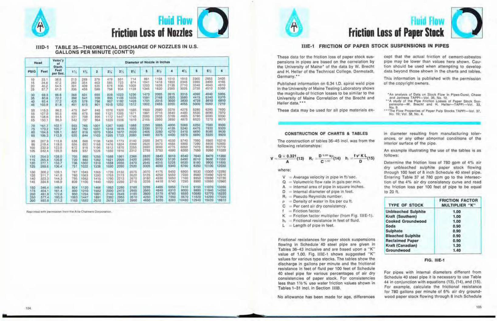
Fluid FlowFriction Loss of Nozzles
Fluid FlowFriction Loss of Paper Stock
IIIE-1 FRICTION OF PAPER STOCK SUSPENSIONS IN PIPES
CONSTRUCTION OF CHARTS & TABLES
No allowance has been made for age, differences
FRICTION FACTORTYPE OF STOCK MULTIPLIER "K"
Unbleached Sulphite 1.00Kraft (Southern) 1.00Cooked Groundwood 1.00Soda 0.90Sulphate 0.90Bleached Sulphite 0.90Reclaimed Paper 0.90Kraft (Canadian) 1.20Groundwood 1.40
For pipes with internal diameters different fromSchedule 40 steel pipe it is necessary to use Table44 in conjunction with equations (13), (14), and (15).For example, calculate the frictional resistancefor 780 gallons per minute of 6% air dry ground-wood paper stock flowing through 8 inch Schedule
FIG. IIIE-1
* An analysis of Data on Stock Flow in Pipes-Durst, Chaseand Jenness TAPPI-Vol. 35, No. 12.
'" '" A study of the Pipe Friction Losses of Paper Stock Sus-pensions-W. Brecht and H. Heller-TAPPI-Vol. 33,NO.9.
---"'The Flow Properties of Paper Pulp Stocks TAPPI-Vol. 37,No. 10; Vol. 38, No.4.
in diameter resulting from manufacturing toler-ances, or any other abnormal conditions of theinterior surface of the pipe.
An exampie illustrating the use of the tables is asfollows:
Determine the friction loss of 780 gpm of 4% airdry unbleached sulphite paper stock flowingthrough 100 feet of 8 inch Schedule 40 steel pipe.Entering Table 37 at 780 gpm go to the intersec-tion of the 4% air dry consistency curve and readthe friction loss per 100 feet of pipe to be equalto 20 ft.
cept that the actual friction of cement-asbestospipe may be lower than values here shown. Cau-tion shouid be used when attempting to developdata beyond those shown in the charts and tables.
This information is published with the permissionof the copyright owners.
o 0.205 vpC '-'" (14)
Frictional resistances for paper stock suspensionsflowing in Schedule' 40 steel pipe are given inTables 36-43 inclusive and are based upon a "K"value of 1.00. Fig. IlIE-1 shows suggested "K"values for various type stocks. The tables show thedischarge in gallons per minute and the frictionalresistance in feet of fluid per 100 feet of Schedule40 steel pipe for various percentages of air dryconsistencies of paper stock. For consistenciesless than 1V2 % use water friction values shown inTables 1-31 inc!. in Section nIB.
where:
V =Average velocity in pipe in ft/sec.Q = Volumetric flow rate in gals per min.A = Internal area of pipe in square inches.D = Internal diameter of pipe in feet.RE· = Pseudo Reynolds number.p = Density of water in Ibs per cu ft.C =Per cent air dry consistency.f = Friction factor.K = Friction factor mUltiplier (from Fig. tIlE-l).h, = Frictional resistance in feet of fluid.L = Length of pipe in feet.
The construction of tables 36-45 incl. was from thefollowing relationships:
These data for the friction loss of paper stock sus-pensions in pipes are based on the correlation bythe University of Maine' of the data by W. Brechtand H. Heller of the Technical College, Darmstadt,Germany.· *
Published information on 6.34 I.D. spiral weld pipein the University of Maine Testing Laboratory showsthe magnitude of friction losses to be similar to theUniversity of Maine Correlation of the Brecht andHeller data.'"
These data may be used for all pipe materials ex-
v = Q x 0.321(13)A
IIID-1 TABLE 35-THEORETICAL DISCHARGE OF NOZZLES IN U.S.GALLONS PER MINUTE (CONT'D)
Reprinted with permission from the Allis-Chalmers Corporation.
HeadVeloc'y Diameter of Nozzle in Inchesof
PSIGI Disch.
Feet Feet 1}'2 1% 2 2X 2!1 2% 3 3);'2 4 Tセ 5 5X 6perSec.
10 23.1 38.6 213 289 378 479 591 714 851 1158 1510 1915 2365 2855 340515 34.6 47.2 260 354 463 585 723 874 1041 1418 1850 2345 2890 3490 416520 46.2 54.5 301 409 535 676 835 1009 1203 1638 2135 2710 3340 4040 481025 57.7 61.0 336 458 598 756 934 1128 1345 1830 2385 3025 3730 4510 5380
30 69.3 66.8 368 501 655 828 1023 1236 1473 2005 2615 3315 4090 4940 589535 80.8 72.2 398 541 708 895 1106 1335 1591 2168 2825 3580 4415 5340 637040 92.4 77.2 425 578 756 957 1182 1428 1701 2315 3020 3830 4725 5610 681045 103.9 81.8 451 613 801 1015 1252 1512 1802 2455 3200 4055 5000 6050 7210
50 115.5 86.2 475 647 845 1070 1320 1595 1900 2590 3375 4275 5280 6380 760055 127.0 90.5 498 678 886 1121 1385 1671 1991 2710 3540 4480 5530 6690 797060 138.6 94.5 521 708 926 1172 1447 1748 2085 2835 3700 4685 5790 6980 833065 150.1 98.3 542 737 964 1220 1506 1819 2165 2950 3850 4875 6020 7270 8670
70 161.7 102.1 563 765 1001 1267 1565 1888 2250 3065 4000 5060 6250 7560 900075 173.2 105.7 582 792 1037 1310 1619 1955 2330 3170 4135 5240 6475 7820 932080 184.8 109.1 602 818 1070 1354 1672 2020 2405 3280 4270 5410 6690 8080 963085 196.3 112.5 620 844 1103 1395 1723 2080 2480 3375 4400 5575 6890 8320 9920
90 207.9 115.8 638 868 1136 1436 1773 2140 2550 3475 4530 5740 7090 8560 1021095 219.4 119.0 656 892 1168 1476 1824 2200 2625 3570 4655 5900 7290 8800 10500
100 230.9 122.0 672 915 1196 1512 1870 2255 2690 3660 4775 6050 7470 9030 10770105 242.4 125.0 689 937 1226 1550 1916 2312 2755 3750 4890 6200 7650 9260 11020
110 254.0 128.0 705 960 1255 1588 1961 2366 2820 3840 5010 6340 7840 9470 11300115 265.5 130.9 720 980 1282 1621 2005 2420 2865 3930 5120 6490 8010 9680 11550120 277.1 133.7 736 1002 1310 1659 2050 2470 2945 4015 5225 6630 8180 9900 11800125 288.6 136.4 751 1022 1338 1690 2090 2520 3005 4090 5340 6760 8350 10100 12030
130 300.2 139.1 767 1043 1365 1726 2132 2575 3070 4175 5450 6900 8530 10300 12290135 311.7 141.6 760 1063 1390 1759 2173 2620 3125 4250 5550 7030 8680 10490 12510140 323.3 144.3 795 1082 1415 1790 2212 2670 3180 4330 5650 7160 8850 10690 12730145 334.8 146.9 809 1100 1440 1820 2250 2715 3235 4410 5740 7260 6990 10680 12960
150 346.4 149.5 824 1120 1466 1853 2290 2760 3295 4485 5650 7410 9150 11070 13200175 404.1 161.4 890 1210 1582 2000 2473 2985 3560 4840 6310 8000 9890 11940 14250200 461.9 172.6 950 1294 1691 2140 2645 3190 3800 5175 6760 8550 10580 12770 15220250 577.4 193.0 1063 1447 1891 2392 2955 3570 4250 5795 7550 9570 11820 14290 17020300 692.8 211.2 1163 1582 2070 2615 3235 3900 4650 6330 8260 10480 12940 15620 18610
104 105
• $

Fluid FlowFriction Loss of Paper Stock
Fluid FlowFriction Loss of Paper Stock
FRICTION LOSS OF PAPER STOCK SUSPENSIONS IN SCHEDULE 40 STEEL PIPE
TABLE 36
University of Maine Correlation of Brecht and Heller Data
200030 40 50 60 80 100 200 300 400 600 800 1000GALLONS PER MINUTE
20
I .0°0I I I I I I I
6" SCHEDULE 40 PIPE 16.065" 1.0. セ ョ セ
....... !./ .25.'Y<I-"" ".NコUセ
セ p !...--"" ---.....l..-
I..- !...--"" セ V i,...- ..... セuM l--- fj. 25 0;'
0 l..- e:::::.- .....---- :..--- I..-- .....セャMヲ
...... ..... .... r:::::-- セ -::::1........ ..... l.-l.- セNUEiJ> °
.....セ
°t ..... セ ::.... ........ I-""
*..... .... セセ
セNoE/ l---lQzCIl '00 L......'f' ---
I-""
Gl
3
2
100908070
60
W 50a.0:: 40
II.o 30
ooセ 20II:Wa. 15
I-WW 10II. 9Z 8
76
5
Z 4oi=oa:II.
eneno....
Common Terms:
Air Dry (A.D.) Consislency-The weight fraction ofpaper left in a sample after drying in the atmos-phere.
Schedule 40 steel fittings, it is necessary to useequation (13) to determine the flow velocity. Table45 can then be entered on the velocity scale andprojected upward to the intersection with the con-sistency curves. The frictional resistance can nowbe read as before. For the various types of paperstock, the K values from Figure lIIE-1 should beused as multipliers of the frictional resistance.
Example: What is the capacity equivalent of 100TID of 5% B.D. stock? The solution is found byentering Table 46 with 100 TID and proceed to the5% B.D. curve. Read the capacity on the abscissato be 335 U.S. gpm.
If the consistency had been expressed as 5.55%A.D. the first step is to convert A.D. to B.D. i.e.,B.D. = 0.9 x A.D. or B.D. = 0.9 x 5.55 = 5.0, thenproceed as before.
Bone Dry (B.D.) Consislency-The weight fractionof paper left in a sample after drying in an oven at212 0 F or higher. Bone dry stock contains 10 percent less moisture than air dry stock. Therefore,the relationship between the two is:
Bone Dry Consistency = 0.9 x Air Dry Consistency
Tons per Day {TID)-Mill output is generally givenin tons of stock per day. The relationship betweenTID, consistency and capacity is:
TID = Capacity (gpm) x per cent B.D. Consistency16.65
The solution of the equation is shown on Table 46for the normal range of B.D. consistencies.
FRICTION LOSS IN FITTINGS
R_ (0.6771 )0.205 x 4.83 x 62.4
=:.:...:.-'-!-_:..:-:.:.:..:'-'-'-=-'-= 35.1, - (6) "'5'
from Table 46, f = 0.012 and, from Figure IIIE-1,K = 1.4
h, = 0.012 (4.83)' x 100 x 1.4 =57.9 feet0.6771
20 stainless steel pipe. From Section IV, 0 =0.6771 feet and A = 51.85 square inches.
V = 780 x 0.321 セ =4.83 FUSee51.85 Sec
Using the density of the suspension to be the sameas water.
To determine frictional resistance of paper stocksuspensions flowing in elbows and tees use Table45. The curves are drawn for 90 0 short radiuselbows. To determine the frictional resistance foreither 90 0 long radius elbows or 45 0 elbows multi-ply the results obtained from Table 45 by a 0.8factor. To determine the frictional resistance of astandard tee, multiply the results obtained fromTable 45 by a 1.7 factor. The following exampiedemonstrates how to use Table 45.
Find the frictional resistance in an 8 inch Schedule40, short radius 90 0 steel elbow for 900 gallons perminute of 3% air dry consistency of unbleachedsulphite paper stock. Entering Table 45 with 900gallons per minute move horizontally to the inter-section of the 8 inch curve. Proceeding verticallyto the intersection of the 3% air dry consistencycurve results in a frictional resistance value of1 foot.
For fittings with internal diameters different from
106 107
• 2

Fluid FlowFriction Loss of Paper Stock
Fluid FlowFriction Loss of Paper Stock
FRICTION LOSS OF PAPER STOCK SUSPENSIONS IN SCHEDULE 40 STEEL PIPE FRICTION LOSS OF PAPER STOCK SUSPENSIONS IN SCHEDULE 40 STEEL PIPEUniversity of Maine Correlation of Brecht and Heller Data University of Maine Correlation of Brecht and Heller Data
TABLE 37 TABLE 38
I I I I II I I I I I 1 I
10" SCHEOUL 40 PIPE (10.02" 1.0.)
200 300 400 600 800 1000 2000 3000 4000 6000GALLONS PER MINUTE
Q ......
セ .B"A
H+-If----l-+-+-++-H--H-+-If-+++-..........MMMMMZZセWVMMMゥBjNNNM]KNMK HッKKKKKKMhMKMMKMMMKMMMMKMMMMKセ
v I-- L.----"" ......V
40
WC. 30ii:lL0 20
00 15セ
a:w ,
oセC.
I-9
W 8W 7lL 6Z 5(/l
4(/l
0..J 3Z0i= 2(J
i.elL
,200020 30 40 50 60 80 100 200 300 400 600 800'000
GALLONS PER MINUTE
1 I-I 1 1 I 1-
0 8" SCHEDULE 40 PIPE 17.981" 1.0.) . ( .0%0
セ -0!...--'" I . セ .0°
0セL ':25Wol-セ
0 V J..._ セSNWUセPVi.......... V セjNNN⦅ I セ I J..._I.-I セl0
セ セQMM i::tf±l-' v イWセᄋイUE.5 セサL I ::::h::: 1--1 l.- I I -5
セセ}NNNNアNNエエャLN .. '-"!.- I
l']; .5P/o 1.....1...].... 1.-1 Ifv ...........2.5o/ff--0 Z 9:;::>9 lI,J InOA
8 ill ...... ...... ..... : ,? +---7 iii .51'/0 .... V ... ..........
r--6
5,
.B0/0...... ....
4
ciIl .....3 l.----""'"
2
1
7
6
5
a:,wc.
t;j,WlL
Z
(/l(/l
o..J
Zoi=(J
i.elL
wC. 4ii:lL 3og 2セ
•'08
•'09

Fluid FlowFriction Loss of Paper Stock
Fluid FlowFriction Loss of Paper Stock
FRICTION LOSS OF PAPER STOCK SUSPENSIONS IN SCHEDULE 40 STEEL PIPE FRICTION LOSS OF PAPER STOCK SUSPENSIONS IN SCHEDULE 40 STEEL PIPE
University of Maine Correlation 01 Brecht and Heller Data University of Maine Correlation of Brecht and HeUer Data
TABLE 39 TABLE 40
6000200 300 400 600 8001000 2000 30004000GALLONS PER MINUTE
I II I I I I I I
14" SCHEDULE 40 PIPE (13.126" 1.0.
:.....1-- 0
V......
L..- .....
セV ..... . 0
V ......V"'" !Y<.....
NNNNNMZZZZエセjZZZZ l::= ::: ...........1--'" :--- !--,I-- t::: %..... I-- V ..........
0 '*..... ........ ...... ........
0 .......... ...... .............1 ........ .........'"-q. 0_' 0
-In 4 flo/<
---Qi5.01<
..... ..... ........ 0
セ ....... ..... .- .....:J :> fl*
I ...... ..... ..... ........:i ..... セ<C I ..... ..... .....
...... .....
1
40
wa. 30ii:II.o 20
oセ 15
a:Wa. 10I- 9W 8W 7II.
6Z
5l/ll/l 4o....
3Zoセ 2
ii:II.
12" SCHEDULE 40 PIPE (11.938" 1.0.
.... ,
........ L..- ....
...............1.-........ L..- i-- p.
..... ..... V ........ ..................
........ l;:1..... セN......
........i--" .....セ
::::..- :::: :;: セ i-- セN 0
........ L..- "'" ..... / ........ ..... i-- B......... ---0
....... L....- ..... .....04.5% ........ ..... ..... ........ ........
........ .....セ • v " ...... ........0 ..... ..... ......o <'.U"lo
"'"...............
ci ................. ...........
<I: !--,I--...........
1
z
40
200 300 400 600 800 1000 2000 30004000 6000GALLONS PER MINUTE
a:セ 10I- 9W BW 7II. 6
5
wa. 30ii:II.o 20
oo 15セ
l/ll/l 4o.... 3Zoセ 2oii:II.
•110
t111

Fluid FlowFriction Loss of Paper Stock
Fluid FlowFriction Loss of Paper Stock
FRICTION LOSS OF PAPER STOCK SUSPENSIONS IN SCHEDULE 40 STEEL PIPE FRICTION LOSS OF PAPER STOCK SUSPENSIONS IN SCHEDULE 40 STEEL PIPEUniversity of Maine Correlation of Brecht and Heller Data University of Maine Correlation of Brecht and Heller Data
TABLE 41 TABLE 42
,--rI
I I I I18" SCHEDULE 40 PIPE 116.876" 1.0.
0
a
a !E 000
1..-1--"" II-'"f! セ」5
MMセ0
セイZZMセ H--lf H:l--- 42 I/oa セ l--9 I
38 ...... -4;; II..-7 - --- ..... J:,..-,- 3f2'-' ..........セ v -VI I I ..... Vo6 °0 セ B 「5 >-
NセA .Pic .:;;I-
j", I v-r ....... ..!a 1-.1 hoo I I ,.... .....
セ
g! ,... Il..- ""'" ..... v 203.5'°/c セ
IR 'I', i--" .......- セ "'"c 3.0% l--I-- V V
v .......< ,I-- セ
vI--200 300 400 600 800 1000 2000 30004000 6000
GALLONS PER MINUTE
4
W 30.ii:
:5 2
81...a:W10.
セWWU.
Z
Ul 4Ulo..J 3
Zoi= 22a:u.
I I I I II I I I I I I
6" SCHEDULE 40 P PE IHnn" 1.0 \
aVセ 0
IaV セ I I 5.b' 0V
5 !.-f"- I-
セ V V j...-- l--l.- 4 b' or....1-' V I
I I セ 17,a v lS! セ
98 v 0v -- .....7 0- "0 v .......... .......... v6 >- セ5 4.. O'ic 00
.......- v4
セ ;l 0 ....... '-'V 2.n< 0
3 ;j. '"!O .... .......- f-'" "'"Z0
:1 0;.: ....V(J .......
2 -C I-- Vc:r;
'-'I--1
40
200 300 400 500600 8001000 2000 3000 4000 6000
GALLONS PER MINUTE
W0. 3ii:u.o 2
o01...a:w0.
Iiiwu.Z
UlUlo..J
Zoi=(J
ii:u.
112 1h'... -..__......... _ 113
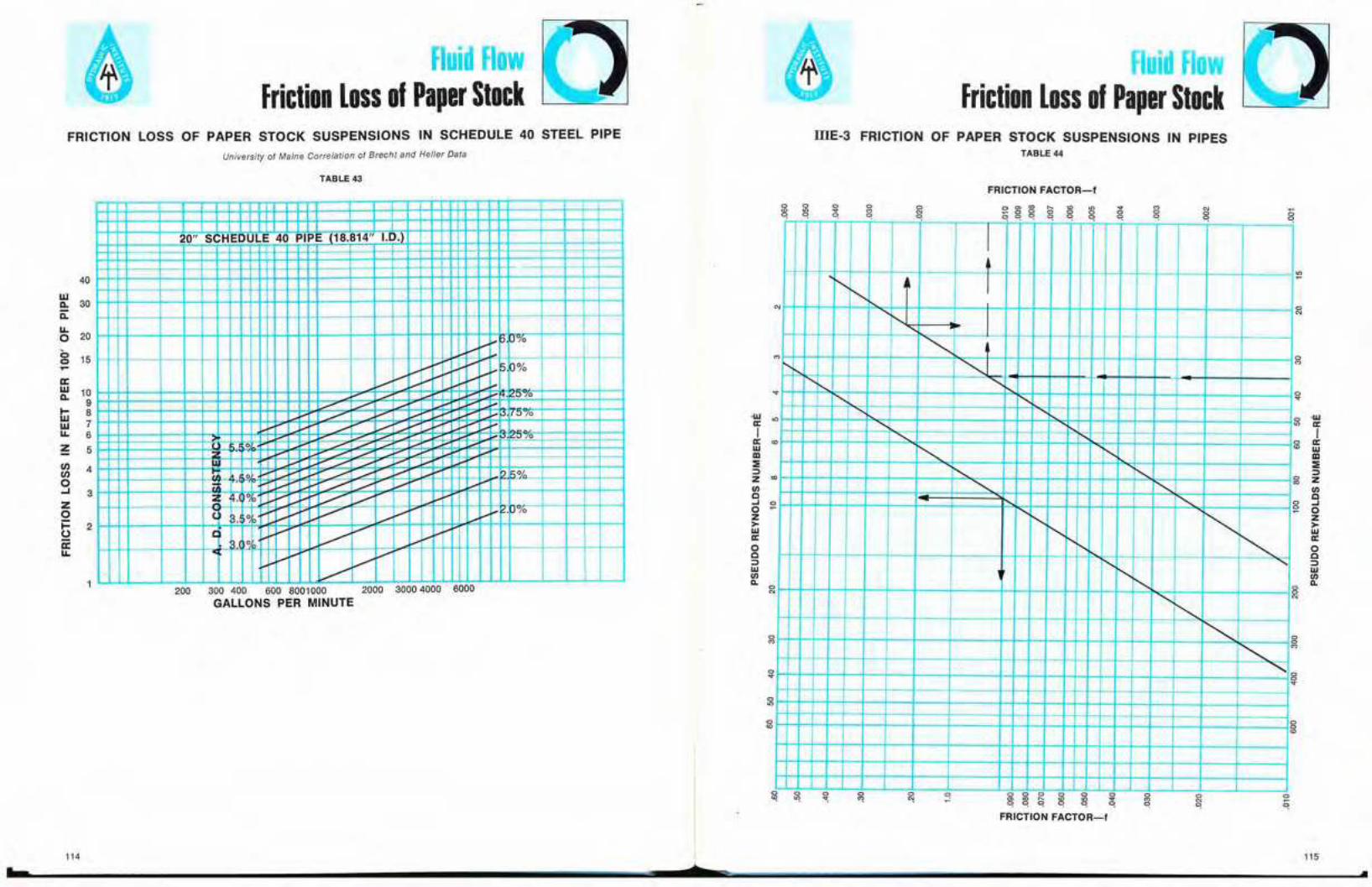
Fluid FlowFriction Loss of Paper Stock
Fluid FlowFriction Loss of Paper Stock
FRICTION LOSS OF PAPER STOCK SUSPENSIONS IN SCHEDULE 40 STEEL PIPE
University 01 Maine Correlation of Brecht and Hefler Data
I1IE·3 FRICTION OF PAPER STOCK SUSPENSIONS IN PIPESTABLE 44
TABLE 43FRICTION FACTOR-I
200 300 400 600 8001000 2000 3000 4000 6000
GALLONS PER MINUTE
aN
aM
a.,
セ Gセ
Ig ffi
III:;:::>
g zl/)C
a ..Ja 0
Z>lIJa:oc::>lIJl/)l1.
セ
a
Na
QmtOr--wt.n "".... 0 0 000 00o 0 0 0 0
aMa
a a:g ;ge, e, e,
I
'" I"-.-N
.......
""セ
M
""i'.......
""".,r--.., .......
"セ
"-........,
"" i'-t--.... r......,セ i"..
:: ""'-" r....... セI"-.-
1'-,..." "'"i'- ",r.......I"-.-
"" I".......I"".......
a
""M
"" aa.,
aa.,
a a a a
aN
aM
-wa:I
a:lIJIII:;:::>zl/)C..JoZ>lIJa:oc::>lIJl/)l1.
I I I I I I I I IT I I II II I I I
20" SCHEDULE 40 PIPE 118.814" I.D.l
i M M セ N セ G W P.....
v .....iMMセ P%v I .....V V v I-- セ -5-0 0
;.-. .......5"l0........ L-- L.-
...... l...--'5""°0
0 I
Y
セ0 ....... ...... y 1"."1<
..... .- ....... ......,0 i.-' J.,.. [....---" ..- I--
0 I-- l.- V V I.-.!-.l%
......
'f v VV 1--1.-
0 vv l.- V V
..............
40
wCo 30c::ILo 20
oo 15....a:w 10Co 9I- 8ltl 7IL 6
Z 5
(/) 4(/)
o.... 3
Zoj:::: 2()
ii:IL
FRICTION FACTOR-I
114 115.' ¢Z --..-

i 10Friction Loss of Paper Stock
FI "d F wFriction Loss of Paper Stock
20f--+----jf---+----i--+----+--+----+--+---+--l-----l
IIIE-4 FRICTION OF PAPER STOCK SUSPENSIONS IN 90·
SHORT RADIUS ELBOWS TABLE 46
IIIE-5 CONVERSION OF TONS OF STOCK PER 24 HOURSAT VARIOUS CONSISTENCIES TO U.S. GPM
PER CENT BONE DRY STOCK
000 0 0 0 0 0 0f 0
000 0 0 0 0 0000 0 0 0 0 0 0 ッセ
00000 セ 00 00 セ セ0 :=a>co セ 00 00 セ セ NN
o20" .===1,8"--..., ,.-----t6' N
9
-
TABLE 45
o
3.0 -6%
/"'5% 1
1----1% AIR DRYCiONSISTENCY セ O 4V, 0$
:;:: 2.04%
セ - l3V, % I:w - , I 3% %___ /.:...:..:-- 2V,00J: 1.0 L セ セ I
セ :: セ ::J-r- セ「セ⦅ゥjL⦅MMB」MQ ⦅MMM]N]MMゥMiGR]P⦅yNセP⦅]]M⦅]⦅ZZャセ 0.5 .J- 'IEg 0.4 セ G (CE§ -__-I- 0.3W '---+-----4--+---+- LONG RADIUS OR 45° ELBOWS MULTIPLY BY .8セ 0.2 _ I tTANDARD TEES MUl:l!PLY-!D" 1·L
f------1---+----jh-V'ETI'CTTY 1ilFEE PER' s e c o n セ
++-8000 >--,I-- _60005000 L.--" I -I4000 I I I ".J-
L =-- 12" « -3000 .:::::::::J" -:;..- I -<- I:::=L Z
/...-l- - --T I 10" ...:-ヲ M M M K M M M M M Q i M M M M K M M M a セ セ ⦅ i ⦅ ⦅ ⦅ L ........"'-+-=_I__r ::ii:-
20001--+--I1--+,/../'" ,/' ./' V -+-- l .t..--- J. +-- i M M セ ⦅/ // ....... l---"......-1 1.t--:::::1.-セ I _ 8"-
QPPPiMMMMKMMKMセMMM」セOM⦅セカMZLカ /IY セ f- t--L セw 800 -r> セ M N i l セ 6" :=セ 600 ¢t/ '" セ _ r - セ:E 500 / I f--1J,l-a: 400 '-/- J.. 4" 13-セ 300 / T ---r::: I I--Ul-
セ '00 Oセ / カMセェ -1T' M ヲ セCl 100 / // ............1 -l r-_
XPセセAセᄃセセセセセセセセイセeセxセaセmセpleMfriction HEAD LOSS INVPセ AN 8" SHORT RADIUS 90°
/ ./ ELBOW FLOWING 900 GPM
UPセセセセセエセセセセiセセ]]e]MM[ OF 3% A. D. STOCK IS 1 FOOT40 -
30 ---/
TONS OF STOCK PER 24 HOURS
"116
•117
•
SectionlI
Characteristicsof Piping Materials
.....' ----------*-----------------

Characteristics of Piping MaterialsSteel Pipe
, $
IVA-1 PIPE DIMENSIONS; WROUGHT STEEL AND STAINLESS STEEL(ANSI 836.10-1975 AND ANSI 836.19-19652
)
NOTES:1. Covers pipe manufactured to specifications noted in Table.
2. Data reprinted by permission of The American Society of Mechanical Engineers, 345 East 45th St., NewYork, N.Y.
3. "S" suffix to schedule number denotes wall thickness pertains only to stainless steel pipe. Stainlesssteel pipe schedule numbers with dimensions and schedule numbers the same as steel pipe are notsuffixed in this table.
Size 10ENTIFICATION Wall Internal Internal Internal Internal dONominal & Thickness Diameter Area Diameter Area f=O.00015 Ft.(Outside API Standard Schedule Inches Inches Square Feet Square
Diameter) Standard X·Strong Number Inches FeetXX-Strong
y, lOS 0.049 0.307 0.0740 0.0256 0.00051 0.005865L STD 40 0.068 0.269 0.0568 0.0224 0.00040 0.006691
(.405) 5L XS 80 0.095 0.215 0.0363 0.0179 0.00025 0.008372
y, lOS 0.065 0.410 0.1320 0.0342 0.00092 0.0043905L STD 40 0.088 0.364 0.1041 0.0303 0.00072 0.004945
(.540) 5L XS 80 0.119 0.302 0.0716 0.0252 0.00050 0.005960
'Yo lOS 0.065 0.545 0.2333 0.0454 0.00162 0.0033035L STD 40 0.091 0.493 0.1909 0.0411 0.00133 0.003651
(.675) 5L XS 80 0.126 0.423 0.1405 0.0353 0.00098 0.004255
'!2 5S 0.065 0.710 0.3959 0.0592 0.00275 0.002535lOS 0.083 0.674 0.3568 0.0562 0.00248 0.002671
(.840) 5L STD 40 0.109 0.622 0.3039 0.0518 0.00211 0.0028945L XS 80 0.147 0.546 0.2341 0.0455 0.00163 0.003297
160 0.188 0.464 0.1691 0.0387 0.00117 0.0038795L XXS 0.294 0.252 0.0499 0.0210 0.00035 0.007143
'v. 5S 0.065 0.920 0.6648 0.0767 0.00462 0.001957lOS 0.083 0.884 0.6138 0.0737 0.00426 0.002036
(1.050) 5L STD 40 0.113 0.824 0.5333 0.0687 0.00370 0.0021845L XS 80 0.154 0.742 0.4324 0.0618 0.00300 0.002426
160 0.219 0.612 0.2942 0.0510 0.00204 0.0029415L XXS 0.308 0.434 0.1479 0.0362 0.00103 0.004147
1 5S 0.065 1.185 1.1029 0.0988 0.00766 0.001519lOS 0.109 1.097 0.9452 0.0914 0.00656 0.001641
(1.315) 5L STD 40 0.133 1.049 0.8643 0.0874 0.00600 0.0017165L XS 80 0.179 0.957 0.7193 0.0798 0.00500 0.001881
160 0.250 0.815 0.5217 0.0679 0.00362 0.0022095L XXS 0.358 0.599 0.2818 0.0499 0.00196 0.003005
11/4 5S 0.065 1.530 1.8385 0.1275 0.01277 0.001176lOS 0.109 1.442 1.6331 0.1202 0.01134 0.001248
(1.660) 5L STD 40 0.140 1.380 1.4957 0.1150 0.01039 0.0013045L XS 80 0.191 1.278 1.2828 0.1065 0.00891 0.001408
160 0.250 1.160 1.0568 0.0967 0.00734 0.0015525L XXS 0.382 0.896 0.6305 0.0747 0.00438 0.002009
1'!2 5S 0.065 1.770 2.4606 0.1475 0.01709 0.001017lOS 0.109 1.682 2.2220 0.1402 0.01543 0.001070
(1.900) 5L STD 40 0.145 1.610 2.0358 0.1342 0.01414 0.0011185L XS 80 0.200 1.500 1.7671 0.1250 0.01227 0.001200
160 0.281 1.338 1.4061 0.1115 0.00976 0.0013455L XXS 0.400 1.100 0.9503 0.0917 0.00660 0.001636
121
.
Characteristics of Piping MaterialsSteel Pipe
Char cteri tic of PipiSteel Pipe
IVA-1 PIPE DIMENSIONS; WROUGHT STEEL AND STAINLESS STEEL
Size IDENTIFICATION Wall Internal Internal Inlernal Internal ,/0Nominal & Thickness Diameter Area Diameter Area ,,=0.00015Ft.(Outside API Standard Schedule Inches Inches Square Feet Square
Diameter) Standard X-Strong Number Inches FeetXX-Strong
2 5L 5LX 5S 0.065 2.245 3.9584 0.1871 0.02749 0.000802lOS 0.109 2.157 3.6542 0.1798 0.02538 0.000834
(2.375) 5L 5LX STD 40 0.154 2.067 3.3556 0.1723 0.02330 0.0008715L 5LX XS 80 0.218 1.939 2.9529 0.1616 0.02051 0.000928
160 0.344 1.687 2.2352 0.1406 0.01522 0.0010675L 5LX XXS 0.436 1.503 1.7742 0.1253 0.01232 0.001198
2'h 5L 5LX 5S 0.083 2.709 5.7638 0.2258 0.04003 0.000664lOS 0.120 2.635 5.4532 0.2196 0.03787 0.000683
(2.875) 5L 5LX STD 40 0.203 2.469 4.7878 0.2058 0.03325 0.0007295L5LX XS 80 0.276 2.323 4.2383 0.1936 0.02943 0.000775
160 0.375 2.125 3.5466 0.1771 0.02463 0.0008475L5LX XXS 0.552 1.771 2.4634 0.1476 0.01711 0.001016
3 5L5LX 5S 0.083 3.334 8.7301 0.2778 0.06063 0.000540(3.500) lOS 0.120 3.260 8.3469 0.2717 0.05797 0.000552
5L 5LX 0.125 3.250 8.2958 0.2708 0.05761 0.0005545L 5LX 0.156 3.188 7.9823 0.2657 0.05543 0.0005655L 5LX 0.188 3.124 7.6650 0.2603 0.05323 0.0005765L 5LX STD 40 0.216 3.068 7.3927 0.2557 0.05134 0.0005875L 5LX 0.250 3.000 7.0686 0.2500 0.04909 0.0006005L 5LX 0.281 2.938 6.7794 0.2448 0.04708 0.0006135L5LX XS 80 0.300 2.900 6.6052 0.2417 0.04587 0.000621
160 0.438 2.624 5.4078 0.2187 0.03755 0.0006865L 5LX XXS 0.600 2.300 4.1548 0.1917 0.02885 0.000783
3'h 5L 5LX 5S 0.083 3.834 11.5450 0.3195 0.08017 0.000469(4.000) lOS 0.120 3.760 11.1036 0.3133 0.07711 0.000479
5L 5LX 0.125 3.750 11.0447 0.3125 0.07670 0.0004805L 5LX 0.156 3.688 10.6825 0.3073 0.07418 0.0004885L 5LX 0.188 3.624 10.3149 0.3020 0.07163 0.0004975L 5LX STD 40 0.226 3.548 9.8868 0.2957 0.06866 0.0005075L 5LX 0.250 3.500 9.6211 0.2917 0.06681 0.0005145L 5LX 0.281 3.438 9.2833 0.2865 0.06447 0.0005245L 5LX XS 80 0.318 3.364 8.8880 0.2803 0.06172 0.000535
4 5L 5LX 5S 0.083 4.334 14.7526 0.3612 0.10245 0.000415(4.500) lOS 0.120 4.260 14.2531 0.3550 0.09898 0.000423
5L 5LX 0.125 4.250 14.1863 0.3542 0.09852 0.0004245L 5LX 0.156 4.188 13.7754 0.3490 0.09566 0.0004305L5LX 0.188 4.124 13.3576 0.3437 0.09276 0.0004365L 5LX 0.219 4.062 12.9589 0.3385 0.08999 0.0004435L 5LX STD 40 0.237 4.026 12.7303 0.3355 0.08841 0.0004475L5LX 0.250 4.000 12.5664 0.3333 0.08727 0.0004505L 5LX 0.281 3.938 12.1798 0.3282 0.08458 0.0004575L 5LX 0.312 3.876 11.7993 0.3230 0.08194 0.0004645L 5LX XS 80 0.337 3.826 11.4969 0.3188 0.07984 0.0004705L 5LX 120 0.438 3.624 10.3149 0.3020 0.07163 0.0004975L 5LX 160 0.531 3.438 9.2833 0.2865 0.06447 0.0005245L 5LX XXS 0.674 3.152 7.8030 0.2627 0.05419 0.000571
5 5S 0.109 5.345 22.4381 0.4454 0.15582 0.000337(5.563) lOS 0.134 5.295 22.0202 0.4413 0.15292 0.000340
5L 0.156 5.251 21.6558 0.4376 0.15039 0.0003435L 0.188 5.187 21.1311 0.4323 0.14674 0.0003475L 0.219 5.125 20.6290 0.4271 0.14326 0.0003515L STD 40 0.258 5.047 20.0058 0.4206 0.13893 0.0003575L 0.281 5.001 19.6428 0.4163 0.13641 0.0003605L 0.312 4.939 19.1588 0.4116 0.13305 0.0003645L 0.344 4.875 18.6655 0.4063 0.12962 0.0003695L XS 80 0.375 4.813 18.1937 0.4011 0.12635 0.0003745L 120 0.500 4.563 16.3528 0.3803 0.11356 0.000394
160 0.625 4.313 14.6100 0.3594 0.10146 0.0004175L XXS 0.750 4.063 12.9653 0.3386 0.09004 0.000443
122
IVA-1 PIPE DIMENSIONS; WROUGHT STEEL AND STAINLESS STEEL
Size IDENTIFICATION Wall Internal Internal Internal Internal ,/0Nominal & Thickness Diameter Area Diameter Area £=0.00015Ft.(Outside API Standard Schedule Inches Inches Square Feet Square
Diameter) Standard X-Strong Number Inches FeetXX-Strong
6 5L5LX 5S 0.109 6.407 32.2403 0.5339 I 0.22389 0.000281(6.625) lOS 0.134 6.357 31.7391 0.5298 0.22041 0.000283
5L 5LX 0.188 6.249 30.6698 0.5208 0.21299 0.0002885L 5LX 0.219 6.187 30.0642 0.5156 0.20878 0.0002915L 5LX 0.250 6.125 29.4647 0.5104 0.20462 0.0002945L 5LX STD 40 0.280 6.065 28.8903 0.5054 0.20063 0.0002975L 5LX 0.312 6.001 28.2838 0.5001 0.19642 0.0003005L 5LX 0.344 5.937 27.6837 0.4948 0.19225 0.0003035L 5LX 0.375 5.875 27.1085 0.4896 0.18825 0.0003065L 5LX XS 80 0.432 5.761 26.0667 0.4801 0.18102 0.0003125L 5LX 120 0.562 5.501 23.7669 0.4584 0.16505 0.0003275L 5LX 160 0.719 5.187 21.1311 0.4323 0.14674 0.000347
5L XXS 0.864 4.897 18.8343 0.4081 0.13079 0.000368
8 5S 0.109 8.407 55.5101 0.7006 0.38549 0.000214(8.625) 10S 0.148 8.329 54.4848 0.6941 0.37837 0.000216
5L 5LX 0.188 8.249 53.4432 0.6874 0.37113 0.0002185LX 0.203 8.219 53.0552 0.6849 0.36844 0.000219
5L 5LX 0.219 8.187 52.6429 0.6823 0.36558 0.0002205L 5LX 20 0.250 8.125 51.8486 0.6771 0.36006 0.0002225L 5LX 30 0.277 8.071 51.1617 0.6726 0.35529 0.0002235L 5LX 0.312 8.001 50.2781 0.6668 0.34915 0.0002255L 5LX STD 40 0.322 7.981 50.0270 0.6651 0.34741 0.0002265L 5LX 0.344 7.937 49.4769 0.6614 0.34359 0.0002275L 5LX 0.375 7.875 48.7070 0.6563 0.33824 0.0002295L 5LX 60 0.406 7.813 47.9430 0.6511 0.33294 0.0002305L 5LX 0.438 7.749 47.1608 0.6458 0.32751 0.0002325L 5LX XS 80 0.500 7.625 45.6635 0.6354 0.31711 0.000236
8 5L 5LX 100 0.594 7.437 43.4396 0.6198 0.30166 0.000242(8.625) 120 0.719 7.187 40.5681 0.5989 0.28172 0.000250
140 0.812 7.001 38.4955 0.5834 0.26733 0.0002575L XXS 0.875 6.875 37.1223 0.5729 0.25779 0.000262
160 0.906 6.813 36.4558 0.5678 0.25317 0.000264
10 5S 0.134 10.482 86.2935 0.8735 0.59926 0.000172(10.750) lOS 0.165 10.420 85.2757 0.8683 0.59219 0.000173
5L 5LX 0.188 10.374 84.5245 0.8645 0.58698 0.0001745L 5LX 0.203 10.344 84.0363 0.8620 0.58359 0.0001745L 5LX 0.219 10.312 83.5172 0.8593 0.57998 0.0001755L 5LX 20 0.250 10.250 82.5159 0.8542 0.57303 0.0001765L 5LX 0.279 10.192 81.5847 0.8493 0.56656 0.0001775L 5LX 30 0.307 10.136 80.6906 0.8447 0.56035 0.0001785L 5LX 0.344 10.062 79.5167 0.8385 0.55220 0.0001795L 5LX STD 40 0.365 10.020 78.8543 0.8350 0.54760 0.0001805L 5LX 0.438 9.874 76.5731 0.8228 0.53176 0.0001825L 5LX XS 60 0.500 9.750 74.6619 0.8125 0.51849 0.000185
80S' 0.500 9.750 74.6619 0.8125 0.51849 0.00018580 0.594 9.562 71.8104 0.7968 0.49868 0.000188
5L 5LX 100 0.719 9.312 68.1045 0.7760 0.47295 0.000193120 0.844 9.062 64.4968 0.7552 0.44789 0.000199
XXS 140 1.000 8.750 60.1320 0.7292 0.41758 0.000206160 1.125 8.500 56.7450 0.7083 0.39406 0.000212
I l'Does Not Conform To USA 836.10-1959
123
bn-.- <z....] セ セ セ ⦅ セ ⦅ セ ] ................................... -----
Characteristics of Piping MaterialsSteel Pipe
Characteristics of Piping MaterialsSteel Pipe
IVA-1 PIPE DIMENSIONS; WROUGHT STEEL AND STAINLESS STEEL
Size IDENTIFICATION Wall Internal Internal Internal Internal dONominal & Thickness Diameter Area Diameter Area £=0.00015Ft.(Outside API Standard Schedule Inches Inches Square Feet Square
Diameter) Standard X-Strong Number Inches FeetXX-Strong
12 5S 0.156 12.438 121.5041 1.0365 0.84378 0.000145(12.750) lOS 0.180 12.390 120.5681 1.0325 0.83728 0.000145
5LX 0.203 12.344 119.6745 1.0287 0.83107 0.0001465L 5LX 0.219 12.312 119.0549 1.0260 0.82677 0.0001465L 5LX 20 0.250 12.250 117.8588 1.0208 0.81846 0.0001475L 5LX 0.281 12.188 116.6688 1.0157 0.81020 0.0001485L 5LX 0.312 12.126 115.4848 1.0105 0.80198 0.0001485L 5LX 30 0.330 12.090 114.8002 1.0075 0.79722 0.0001495L 5LX 0.344 12.062 114.2690 1.0052 0.79354 0.0001495L 5LX STD 0.375 12.000 113.0973 1.0000 0.78540 0.000150
40S' 0.375 12.000 113.0973 1.0000 0.78540 0.0001505LX 40 0.406 11.938 111.9317 0.9948 0.77730 0.000151
5L 5LX 0.438 11.874 110.7348 0.9895 0.76899 0.0001525L 5LX XS 0.500 11.750 108.4340 0.9792 0.75301 0.000153
80S' 0.500 11.750 108.4340 0.9792 0.75301 0.0001535L 5LX 60 0.562 11.626 106.1575 0.9688 0.73721 0.0001555L 5LX 80 0.688 11.374 101.6053 0.9478 0.70559 0.000158
100 0.844 11.062 96.1075 0.9218 0.66741 0.000163XXS 120 1.000 10.750 90.7626 0.8958 0.63030 0.000167
140 1.125 10.500 86.5901 0.8750 0.60132 0.000171160 1.312 10.126 80.5315 0.8438 0.55925 0.000178
14 5S 0.156 13.688 147.1533 1.1407 1.0219 0.000132(14.000) 5L 5LX lOS' 0.188 13.624 145.7804 1.1353 1.0124 0.000132
5LX 10 0.210 13.580 144.8403 1.1317 1.0058 0.0001335LX 0.219 13.562 144.4566 1.1302 1.0032 0.000133
5L 5LX 0.250 13.500 143.1388 1.1250 0.9940 0.0001335L 5LX 0.281 13.438 141.8271 1.1198 0.9849 0.0001345L 5LX 20 0.312 13.376 140.5214 1.1147 0.9758 0.0001355L 5LX 0.344 13.312 139.1799 1.1093 0.9665 0.0001355L 5LX STD 30 0.375 13.250 137.8865 1.1042 0.9575 0.0001365L 5LX 0.438 13.124 135.2765 1.0937 0.9394 0.000137
5LX 0.469 13.062 134.00 1.0885 0.9306 0.0001385L 5LX XS 0.500 13.000 132.73 1.0833 0.9218 0.000138
60 0.594 12.812 128.92 1.0677 0.8953 0.0001405L 5LX 80 0.750 12.500 122.72 1.0417 0.8522 0.000144
100 0.938 12.124 115.45 1.0103 0.8017 0.000148120 1.094 11.812 109.58 0.9843 0.7610 0.000152140 1.250 11.500 103.87 0.9583 0.7213 0.000157160 1.406 11.188 98.31 0.9323 0.6827 0.000161
2.000 10.000 78.54 0.8333 0.5454 0.0001802.125 9.750 74.66 0.8125 0.5185 0.0001852.200 9.600 72.38 0.8000 0.5027 0.0001882.500 9.000 63.62 0.7500 0.4418 0.000200
16 5S 0.165 15.670 192.85 1.3058 1.3393 0.000115(16.000) 5L 5LX 108* 0.188 15.624 191.72 1.3020 1.3314 0.000115
5L 5LX 0.219 15.562 190.20 1.2968 1.3209 0.0001165L 5LX 10 0.250 15.500 188.69 1.2917 1.3104 0.0001165L 5LX 0.281 15.438 187.19 1.2865 1.2999 0.0001175L 5LX 20 0.312 15.376 185.68 1.2813 1.2895 0.0001175L 5LX 0.344 15.312 184.14 1.2760 1.2788 0.0001185L 5LX STD 30 0.375 15.250 182.65 1.2708 1.2684 0.0001185L 5LX 0.438 15.124 179.65 1.2603 1.2476 0.000119
5LX 0.469 15.062 178.18 1.2552 1.2374 0.0001205L 5LX XS 40 0.500 15.000 176.71 1.2500 1.2272 0.000120
60 0.656 14.688 169.44 1.2240 1.1767 0.00012380 0.844 14.312 160.88 1.1927 1.1172 0.000126
100 1.031 13.938 152.58 1.1615 1.0596 0.000129120 1.219 13.562 144.46 1.1302 1.0032 0.000133140 1.438 13.124 135.28 1.0937 0.9394 0.000137160 1.594 12.812 128.92 1.0677 0.8953 0.000140
*Does Not Conform To USA 836.10-1959
124
IVA-1 PIPE DIMENSIONS; WROUGHT STEEL AND STAINLESS STEEL
Size IDENTIFICATION Wall Internal Internal Internal Internal dONominal & Thickness Diameter Area Diameter Area £=0.00015Ft.(Outside API Standard Schedule Inches Inches Square Feet Square
Diameter) Standard X-Strong Number Inches FeetXX-Strong
18 5S 0.165 17.670 245.22 1.4725 1.7029 0.000102(18.000) 5L 5LX lOS' 0.188 17.624 243.95 1.4687 1.6941 0.000102
5L 5LX 10 0.250 17.500 240.53 1.4583 1.6703 0.0001035L 5LX 0.281 17.438 238.83 1.4532 1.6585 0.0001035L 5LX 20 0.312 17.376 237.13 1.4480 1.6467 0.0001045L 5LX 0.344 17.312 235.39 1.4427 1.6346 0.0001045L 5LX STD 0.375 17.250 233.71 1.4375 1.6230 0.000104
5LX 0.406 17.188 232.03 1.4323 1.6113 0.0001055L 5LX 30 0.438 17.124 230.30 1.4270 1.5993 0.000105
5LX 0.469 17.062 228.64 1.4218 1.5878 0.0001055L 5LX XS 0.500 17.000 226.98 1.4167 1.5763 0.0001065L 5LX 40 0.562 16.876 223.68 1.4063 1.5533 0.0001075L 5LX 60 0.750 16.500 213.82 1.3750 1.4849 0.000109
80 0.938 16.124 204.19 1.3437 1.4180 0.000112100 1.156 15.688 193.30 1.3073 1.3423 0.000115120 1.375 15.250 182.65 1.2708 1.2684 0.000118140 1.562 14.876 173.80 1.2397 1.2070 0.000121160 1.781 14.436 163.72 1.2032 1.1370 0.000125
20 5S 0.188 19.624 302.46 1.6353 2.1004 0.0000917(20.000) 108· 0.218 19.564 300.61 1.6303 2.0876 0.0000920
5L 5LX 10 0.250 19.500 293.65 1.6250 2.0739 0.00009235L 5LX 0.281 19.438 296.75 1.6198 2.0608 0.00009265L 5LX 0.312 19.376 294.86 1.6147 2.0476 0.00009295L 5LX 0.344 19.312 292.92 1.6093 2.0341 0.00009325L 5LX STD 20 0.375 19.250 291.04 1.6042 2.0211 0.0000935
5LX 0.406 19.188 289.17 1.5990 2.0081 0.00009385L 5LX 0.438 19.124 287.24 1.5937 1.9947 0.0000941
5LX 0.469 19.062 285.38 1.5885 1.9818 0.00009445L 5LX XS 30 0.500 19.000 283.53 1.5833 1.9689 0.0000947
40 0.594 18.812 277.95 1.5677 1.9302 0.00009575L 5LX 60 0.812 18.375 265.21 1.5313 1.8417 0.0000980
80 1.031 17.938 252.72 1.4948 1.7550 0.0001009100 1.281 17.438 238.83 1.4532 1.6585 0.0001032120 1.500 17.000 226.98 1.4167 1.5763 0.0001059140 1.750 16.500 213.82 1.3750 1.4849 0.0001091160 1.969 16.062 202.62 1.3385 1.4071 0.0001121
22 5S 0.188 21.624 367.25 1.8020 2.5503 0.0000832(22.000) lOS' 0.218 21.564 365.21 1.7970 2.5362 0.0000835
5L 5LX 10 0.250 21.500 363.05 1.7917 2.5212 0.00008375L 5LX 0.261 21.438 360.96 1.7865 2.5067 0.00008405L 5LX 0.312 21.376 358.87 1.7813 2.4922 0.00008425L 5LX 0.344 21.312 356.73 1.7760 2.4773 0.00008455L 5LX STD 20 0.375 21.250 354.66 1.7708 2.4629 0.0000847
5LX 0.406 21.188 352.59 1.7657 2.4485 0.00008505L 5LX 0.438 21.124 350.46 1.7603 2.4338 0.0000852
5LX 0.469 21.062 348.41 1.7552 2.4195 0.00008555L 5LX XS 30 0.500 21.000 346.36 1.7500 2.4053 0.00008575L 5LX 0.625 20.750 338.16 1.7292 2.3484 0.0000867
60 0.875 20.250 322.06 1.6875 2.2365 0.000088980 1.125 19.750 306.35 1.6458 2.1275 0.0000911
100 1.375 19.250 291.04 1.6042 2.0211 0.0000935120 1.625 18.750 276.12 1.5625 1.9175 0.0000960140 1.875 18.250 261.59 1.5208 1.8166 0.0000986160 2.125 17.750 247.45 1.4792 1.7184 0.0001014
*Does Not Conform To USA 836.10·1959
125..b .C _

Characteristics of Piping MaterialsSteel Pipe
Characteristics of Piping MaterialsSteel Pipe
IVA-1 PIPE DIMENSIONS; WROUGHT STEEL AND STAINLESS STEEL
Size IDENTIFICATION Wall Internal Internal Internal Internal dONominal & Thickness Diameter Area Diameter Area ,,=0.00015Ft.(Outside API Standard Schedule Inches Inches Square Feet Square
Diameter) Standard X-Strong Number Inches Feetx x セ s ャ イ ッ ョ ァ
24 5S 0.218 23.564 436.10 1.9637 3.0285 0.0000764(24.000) 5L 5LX 10 0.250 23.500 433.74 1.9583 3.0121 0.0000766
5L 5LX 0.281 23.438 431.45 1.9532 2.9962 0.00007685L 5LX 0.312 23.376 429.17 1.9480 2.9804 0.00007705L 5LX 0.344 23.312 426.82 1.9427 2.9641 0.00007725L 5LX STD 20 0.375 23.250 424.56 1.9375 2.9483 0.0000774
5LX 0.406 23.188 422.30 1.9323 2.9326 0.00007765L 5LX 0.438 23.124 419.97 1.9270 2.9164 0.0000778
5LX 0.469 23.062 417.72 1.9218 2.9008 0.00007815L 5LX XS 0.500 23.000 415.48 1.9167 2.8852 0.00007835L 5LX 30 0.562 22.876 411.01 1.9063 2.8542 0.00007875L 5LX 40 0.688 22.624 402.00 1.8853 2.7917 0.0000796
60 0.969 22.062 382.28 1.8385 2.6547 0.000081680 1.219 21.562 365.15 1.7968 2.5357 0.0000835
100 1.531 20.938 344.32 1.7448 2.3911 0.0000860120 1.812 20.376 326.08 1.6980 2.2645 0.0000883140 2.062 19.876 310.28 1.6563 2.1547 0.0000906160 2.344 19.312 292.92 1.6093 2.0341 0.0000932
26 5L 5LX 0.250 25.500 510.71 2.1250 3.5466 0.0000706(26.000 5L 5LX 0.281 25.438 508.22 2.1198 3.5293 0.0000708
5L 5LX 10 0.312 25.376 505.75 2.1147 3.5122 0.00007095L 5LX 0.344 25.312 503.20 2.1093 3.4945 0.00007115L 5LX STD 0.375 25.250 500.74 2.1042 3.4774 0.0000713
5LX 0.406 25.188 498.28 2.0990 3.4603 0.00007155L 5LX 0.438 25.124 495.76 2.0937 3.4427 0.0000716
5LX 0.469 25.062 493.31 2.0885 3.4258 0.00007185L 5LX XS 20 0.500 25.000 490.87 2.0833 3.4088 0.00007205L 5LX 0.562 24.876 486.02 2.0730 3.3751 0.0000724
28 5L 5LX 0.250 27.500 593.96 2.2917 4.1247 0.0000655(28.000) 5L 5LX 0.281 27.438 591.28 2.2865 4.1061 0.0000656
5L 5LX 10 0.312 27.376 588.61 2.2813 4.0876 0.00006585LX 0.344 27.312 585.86 2.2760 4.0685 0.0000659
5L 5LX STD 0.375 27.250 583.21 2.2708 4.0501 0.00006615LX 0.406 27.188 580.56 2.2657 4.0316 0.0000662
5L 5LX 0.438 27.124 577.83 2.2603 4.0127 0.00006645LX 0.469 27.062 575.19 2.2552 3.9944 0.0000665
5L 5LX XS 20 0.500 27.000 572.56 2.2500 3.9761 0.00006675L 5LX 30 0.625 26.750 562.00 2.2292 3.9028 0.0000673
30 5L 5LX 5S 0.250 29.500 683.49 2.4583 4.7465 0.0000610(30.000) 5L 5LX 0.281 29.438 680.62 2.4532 4.7265 0.0000611
5L 5LX 10 0.312 29.376 677.76 2.4480 4.7067 0.00006135LX 0.344 29.312 674.81 2.4427 4.6862 0.0000614
5L 5LX STD 0.375 29.250 671.96 2.4375 4.6664 0.00006155LX 0.406 29.188 669.11 2.4323 4.6466 0.0000617
5L 5LX 0.438 29.124 666.18 2.4270 4.6263 0.00006185LX 0.469 29.062 663.35 2.4218 4.6066 0.0000619
5L 5LX XS 20 0.500 29.000 660.52 2.4167 4.5869 0.00006215L 5LX 30 0.625 28.750 649.18 2.3958 4.5082 0.0000626
32 5L 5LX 0.250 31.500 779.31 2.6250 5.4119 0.0000571(32.000) 5L 5LX 0.281 31.438 776.25 2.6198 5.3906 0.0000573
5L 5LX 10 0.312 31.376 773.19 2.6147 5.3694 0.00005745LX 0.344 31.312 770.04 2.6093 5.3475 0.0000575
5L 5LX STD 0.375 31.250 766.99 2.6042 5.3263 0.00005765LX 0.406 31.188 763.95 2.5990 5.3052 0.0000577
5L 5LX 0.438 31.124 760.82 2.5937 5.2835 0.00005785LX 0.469 31.062 757.79 2.5885 5.2624 0.0000579
5L 5LX XS 20 0.500 31.000 754.77 2.5833 5.2414 0.00005815L 5LX 30 0.625 30.750 742.64 2.5625 5.1572 0.00005855L 5LX 40 0.688 30.624 736.57 2.5520 5.1151 0.0000588
126
IVA-1 PIPE DIMENSIONS; WROUGHT STEEL AND STAINLESS STEEL
Size IDENTIFiCATION Wall Internal Internal Internal Internal dONominal & Thickness Diameter Area Diameter· Area ,=0.00015Ft.(Outside API Standard Schedule Inches Inches Square Feet Square
Diameter) Standard X-Strong Number Inches FeetXX-Strong
34 5L 5LX 0.250 33.500 881.41 2.7917 6.1209 0.0000537(34.000) 5L 5LX 0.281 33.438 878.15 2.7865 6.0983 0.0000538
5L 5LX 10 0.312 33.376 874.90 2.7813 6.0757 0.00005395LX 0.344 33.312 871.55 2.7760 6.0524 0.0000540
5L 5LX STD 0.375 33.250 868.31 2.7708 6.0299 0.00005415LX 0.406 33.188 865.07 2.7657 6.0074 0.0000542
5L 5LX 0.438 33.124 861.74 2.7603 5.9843 0.00005435LX 0.469 33.062 858.52 2.7552 5.9619 0.0000544
5L 5LX XS 20 0.500 33.000 855.30 2.7500 5.9396 0.00005455L 5LX 30 0.625 32.750 842.39 2.7292 5.8499 0.00005505L 5LX 40 0.688 32.624 835.92 2.7187 5.8050 0.0000552
36 5L 5LX 0.250 35.500 989.80 2.9583 6.8736 0.0000507(36.000) 5L 5LX 0.281 35.438 986.34 2.9532 6.8496 0.0000508
5L 5LX 10 0.312 35.376 982.90 2.9480 6.8257 0.00005095LX 0.344 35.312 979.34 2.9427 6.8010 0.0000510
5L 5LX STD 0.375 35.250 975.91 2.9375 6.7771 0.00005115LX 0.406 35.188 972.48 2.9323 6.7533 0.0000512
5L 5LX 0.438 35.124 968.94 2.9270 6.7288 0.00005125LX 0.469 35.062 965.52 2.9218 6.7050 0.0000513
5L 5LX XS 20 0.500 35.000 962.11 2.9167 6.6813 0.00005145L 5LX 0.562 34.876 955.31 2.9063 6.6341 0.00005165L 5LX 30 0.625 34.750 948.42 2.8958 6.5862 0.00005185L 5LX 40 0.750 34.500 934.82 2.8750 6.4918 0.0000522
127..b ... <n.,....... ....................__......................_ ...... _
Characteristics of Piping MaterialsSteel Pipe
Characteristics of Piping MaterialsSteel Pipe
IVA-2 SPECIFICATIONS FOR WROUGHT STEEL AND STAINLESS STEEL PIPE
ANSI ASTM or APIDesignation Designation Title
636.1 ASTM A53 Welded and Seamless Steel Pipe
636.2 ASTM A72 Welded Wrought Iron Pipe
636.3 ASTM A106 Seamless Carbon-Steel Pipe for High-TemperatureService
636.20 ASTM A120 61ack and Hot-Dipped Zinc-Coated (Galvanized)Welded and Seamless Steel Pipe for Ordinary Uses
636.4 ASTM A134 Electric-Fusion (Arc)-Welded Steel Plate Pipe,Sizes 16 in. and Over
636.5 ASTM A135 Electric-Resistance-Welded Steel Pipe
636.9 ASTM A139 Electric-Fusion (Arc)-Welded Steel Pipe,Sizes 4 in. and Over
636.11 ASTM A155 Electric-Fusion-Welded Steel Pipe for High-Temperature Service
636.16 ASTM A211 Spiral-Welded Steel or Iron Pipe
636.26 ASTM A312 Seamless and Welded Austenitic Stainless Steel Pipe
636.40 ASTM A333 Seamless and Welded Steel Pipe for Low-TemperatureService
636.42 ASTM A335 Seamless Ferritic Alloy Steel Pipe for High-Temperature Service
636.47 ASTM A358 Electric-Fusion-Welded Austenitic Chromium-NickelAlloy Steel Pipe for High-Temperature Service
636.48 ASTM A369 Ferritic Alloy Steel Forged and 60red Pipe forHigh-Temperature Service
636.43 ASTM A376 Seamless Austenitic Steel Pipe for High-TemperatureCentral-Station Service
636.49 ASTM A381 Metal-Arc Welded Steel Pipe for High-PressureTransmission Service
API 5L Line Pipe
API 5LX High-Test Line Pipe
Reprinted with permission from the American Societyof Mechanical Engineers, 345 East 45th Street. N.Y.. N.Y.;ANSI 83610-59.
128
IVA-3 API CASING LIST (See A.P.1. Standard SA)
Size: Nominal Type of Thread Size: Nominal Type of ThreadOutside Weight, Wall Outside Weight, Wall
Diameter. Threads and Thicknessセ
セ . .. Diameter. Threads and Thickness j セ ..Coupling, Grade = . E.: Coupling, Grade =
セE.:
セ • Nセ セ • Nセlb. per ft. セセ
セ ;; lb. per ft. セセ
"in, mm in. mm in. mm in. mm • •= セ = セ
D I D I
4>;, 114,3 9.50 H, J, K 0.205 5,21 X - - - 8% 219,1 24.00 J, K 0.264 6,71 X - - -4>;' 114,3 10.50 J. K 0.224 5,69 X - X - 8% 219,1 28.00 H 0.304 7,72 X - - -4>;, 114,3 11.60 J. K 0.250 6,35 X X X - 8% 219,1 32.00 H 0.352 8,94 X - - -4V, 114,3 11.60 N 0.250 6,35 - X X - 8% 219,1 32.00 J. K 0.352 8,94 X X X X4V, 114,3 13.50 N 0.290 7,37 - X X - 8% 219,1 36.00 J, K 0.400 10,16 X X X X
8% 219,1 36.00 N 0.400 10,16 - X X X
11.50 J. K 0.220 5,59 X - 8% 219,1 40.00 N 0.450 11,43 - X X X5 127,0 - - 8% 219,1 44.00 N 0.500 12,70 - X X X5 127,0 13.00 J, K 0.253 6,43 X X X - 8% 219,1 49.00 N 0.557 14,15 - X X X5 127,0 15.00 J. K 0.296 7,52 X X X X5 127,0 15.00 N 0.296 7,52 - X X X
9% 244,5 32.30 H 0.312 7,92 X5 127,0 18.00 N 0.362 9,19 - X X X - - -9% 244,5 36.00 H 0.352 8,94 X - - -9% 244,5 36.00 J, K 0.352 8,94 X X X -5>;, 139,7 14.00 H, J, K 0.244 6,20 X - - - 9% 244,5 40.00 J. K 0.395 10,03 X X X X
5V, 139,7 15.50 J. K 0.275 6,98 X X X X 9% 244,5 40.00 N 0.395 10,03 - X X X5V, 139,7 17.00 J. K 0.304 7,72 X X X X 9% 244,5 43.50 N 0.435 11,05 - X X X5>;, 139,7 17.00 N 0.304 7,72 - X X X 9% 244,5 47.00 N 0.472 11,99 - X X X5¥, 139,7 20.00 N 0.361 9,17 - X X X 9% 244,5 53.50 N 0.545 13,84 - X X X5¥, 139,7 23.00 N 0.415 10,54 - X X X
1O¥4 273,0 32.75 H 0.279 7,09 X - - -6% 168,3 20.00 H 0.288 7,32 X - - - 1O¥4 273,0 40.50 H 0.350 8,89 X - - -
10¥4 273,0 40.50 J. K 0.350 8,89 X - X -6% 168,3 20.00 J. K 0.288 7,32 X X X - 10¥4 273,0 45.50 J. K 0.400 10,16 X - X X6% 168,3 24.00 J, K 0.352 8,94 X X X X 10¥4 273,0 51.00 J, K, N 0.450 11,43 X - X X6% 168,3 24.00 N 0.352 8,94 - X X X to¥.! 273,0 55.50 N 0.495 12,57 X - X X6% 168,3 28.00 N 0.417 10,59 - X X X6% 168,3 32.00 N 0.475 12,06 - X X X
113/4 298,4 42.00 H 0.333 8,46 X - - -11¥4 298,4 47.00 J, K 0.375 9,52 X - X -
7 177,8 17.00 H 0.231 5,87 X - - - 11¥1 298,4 54.00 J. K 0.435 11,05 X - X -7 177,8 20.00 H, J, K 0.272 6,91 X - - - IH4 298,4 60.00 J, K, N 0.489 12,42 X - X -7 177,8 23.00 J, K 0.317 8,05 X X X X7 177,8 23.00 N 0.317 8,05 - X X X 1'% 339,7 48.00 H 0.330 8,38 X - - -7 177,8 26.00 J. K 0.362 9,19 X X X X 1'% 339,7 54.50 J, K 0.380 9,65 X - X -7 177,8 26.00 N 0.362 9,19 - X X X 13¥8 339,7 61.00 J, K 0.430 10,92 X - X -7 177,8 29.00 N 0.408 10,36 - X X X 1'% 339,7 68.00 J. K 0.480 12,19 X - X -7 177,8 32.00 N 0.453 11,51 - X X X 1'% 339,7 72.00 N 0.514 13,06 X - X -7 177,8 35.00 N 0.498 12,65 - X X X7 177,8 38.00 N 0.540 13,72 - X X X 16 406,4 65.00 H 0.375 9,52 X - - -
16 406,4 75.00 J, K 0.438 11,13 X - X -7% 193,7 24.00 H 0.300 7,62 X - - - 16 406,4 84.00 J. K 0.495 12,57 X - X -7% 193,7 26.40 J, K 0.328 8,33 X X X X7% 193,7 26.40 N 0.328 8,33 - X X X 18% 473,1 87.50 H, J, K 0.435 11,05 X - - -7% 193,7 29.70 N 0.375 9,52 - X X X 20 508,0 94.00 H, J, K 0.438 11,13 X X - -7% 193,7 33.70 N 0.430 10,92 - X X X 20 508,0 106.50 J. K 0.500 12,70 X X - -7% 193,7 39.00 N 0.500 12,70 - X X X 20 508,0 133.00 J, K 0.635 16,13 X X - -
Reprinted with permission from theAmerican Petroleum Institute.
129..b ... ........... セ ...... ............................ _

Characteristics of Piping MaterialsSteel Pipe
Characteristics of Piping MaterialsSteel Pipe
IVA-4 API PLAIN-END LINER LIST
Size:Outside Plain-End Wall
Diameter. Weight Thickness. , , , . ,in. mm Ib/ll kg/m Grade in. mm
D I
3% 88,9 9.91 14,76 J 0.289 7,344 101,6 11.34 16,89 J 0.286 7,264V2 114,3 13.04 19,42 J 0.290 7,375 127,0 17.93 26,71 J 0.362 9,195% 139,7 19.81 29,51 J 0.351 9,1760/8 168,3 27.65 41,18 J 0,417 10,59
Reprinted with permission from theAmerican Petroleum Institute.
IVA-S API TUBING LIST
Size: NominalOutside Weight, Wall Types of
Diameter Threads Grade Thickness Endsland , .
In. mm Coupling in. mmD lb. per ft. t
tt1.050 26,7 1.14 H,J,N 0.113 2,87 n ッ ョ セ u ー ウ ・ エ
1.050 26,7 1.20 H, J, N 0.113 2,87 Ext. Upset1,315 33,4 1.70 H, J, N 0,133 3,38 Non-Upset1.315 33,4 1.72 H, J, N 0.133 3,38 Integral Joint1.315 33,4 1.80 H,J, N 0.133 3,38 Ext. Upset
1.660 42,2 2.10 H,J 0.125 3,18 Integral Joint1.660 42,2 2.30 H,J, N 0.140 3,56 n ッ ョ セ u ー ウ ・ エ
1.660 42,2 2.33 H, J, N 0.140 3,56 Integral Joint1.660 42,2 2.40 H,J, N 0.140 3,56 Ext. Upset
1.900 48,3 2.40 H,J 0.125 3,18 Integral Joint1.900 48,3 2.75 H, J, N 0.145 3,68 Non-Upset1.900 48,3 2.76 H, J, N 0.145 3,68 Integral Joint1.900 48,3 2.90 H, J, N 0.145 3,68 Ext. Upset2.063 52,4 3.25 H, J, N 0,156 3,96 Integral Joint
2% 60,3 4.00 H,J, N 0.167 4,24 n ッ ョ セ u ー ウ ・ エ
2% 60,3 4.60 H, J, N 0,190 4,83 Non-Upset2% 60,3 4.70 H,J,N 0.190 4,83 Ext. Upset2% 60,3 5.80 N 0.254 6,45 n ッ ョ セ u ー ウ ・ エ
2% 60,3 5.95 N 0.254 6,45 Ext. Upset
2'fe 73,0 6.40 H, J, N 0.217 5,51 n ッ ョ セ u ー ウ ・ エ2'fe 73,0 6.50 H,J, N 0.217 5,51 Ext. Upset2Ye 73,0 8.60 N 0.308 7,82 Non-Upset27/e 73,0 8.10 N 0.308 7,82 Ext. Upset
3% 88,9 7.70 H, J, N 0.216 5,49 n ッ ョ セ u ー ウ ・ エ
3V2 88,9 9.20 H, J, N 0.254 6,45 n ッ ョ セ u ー ウ ・ エ
3V2 88,9 9.30 H,J, N 0,254 6,45 Ext. Upset3% 88,9 10.20 H,J, N 0.289 7,34 Non-Upset3% 88,9 12.70 N 0.375 9,52 Non-Upset3Y2 88,9 12.95 N 0.375 9,52 Ext. Upset
4 101,6 9.50 H,J, N 0.226 5,74 n ッ ョ セ u ー ウ ・ エ
4 101,6 11.00 H,J, N 0.262 6,65 Ext. Upset4V2 114,3 12.60 H,J, N 0.271 6,88 Non-Upset4Y2 114,3 12.75 H,J, N 0.271 6.88 Ext. Upset
1 nッョセオーウ・エ tubing is available with regular couplings or special bevel couplings. External-upset tubing is avai:able with イ ・ ァ オ セlar, special bevel or special clearance couplings.
tt For information purposes only.Reprinted with permission from theAmerican Petroleum Institute.
130
IVA-6 API DRILL PIPE L1ST*t
Size: CalculatedOutside Nominal p ャ 。 ゥ ョ セ ・ ョ 、 Wall
Diameter, Weight, Weight, Grade Thickness, Upset Ends, for Weld-on. , Ib/ll . , Tool Jointsin. mm Iblft kg/m in. mm
D w,. I
2% 60,3 4.85 4.43 6,60 E 0.190 4,63 Ext. Upset2% 50,3 6.65 6.26 9,32 D, E 0.280 7,11 Ext. Upset2'l"a 73,0 6.65 6.16 9,16 E 0.217 5,51 Int. Upset or Ext. Upset2'l'a 73,0 10.40 9.72 14,48 D, E 0.362 9,19 Int. Upset or Ext. Upset
3V2 88,9 9.50 8.81 13,12 E 0.254 6,45 Int. Upset or Ext. Upset3V2 88,9 13.30 12.31 18,34 D, E 0.368 9,35 Int. Upset or Ext. Upset3% 88,9 15.50 14.63 21,79 D, E 0,449 11,40 Int. Upset or Ext. Upset
4 101,5 11.85 10.46 15,58 E 0.262 6,65 Int. Upset or Ext. Upset4 101,6 14.00 12.93 19,26 D, E 0.330 8,38 Int. Upset or Ext. Upset4% 114,3 13.75 12.24 18,23 E 0.271 6,88 Int. Upset or Ext. Upset4% 114,3 16.60 14.98 22,31 D, E 0.337 8,56 Int. Upset or Ext. Upset4Vz 114,3 20.00 18.69 27,84 D, E 0.430 10,92 Ext. Upset or Int.-Ext. Upset
5 127,0 16.25 14.87 22,15 E 0.296 7,52 Int. Upset5 127,0 19.50 17.93 26,71 D, E 0.362 9,19 Int.-Ext. Upset5V2 139,7 21.90 19.81 29,51 D, E 0.361 9,17 Int.-Ext. Upset5% 139,7 24.70 22.54 33,57 D, E 0.415 10,54 Int.-Ext. Upset6% 168,3 25.20 22.19 33,05 D, E 0.330 8,38 See footnote
セ Drill pipe in sizes and weights shown italicized are tentative and marking within the API monogram is not permitted.t Drill pipe with special end finish is available under this specification. See API Std SA.
Upset requirements for 6% in.-2S.20 lb. drill pipe not established.
Reprinted with permission from theAmerican Petroleum Institute.
131..b ... ..n ....セセセ⦅セセセ⦅セ _

Characteristics of Piping MaterialsIron Pipe
Characteristics of Piping MaterialsIron Pipe
b
IVB-1 CAST IRON PIPE DIMENSIONSData obtained from Handbook of Cast Iron Pipe,Cast Iron Pipe Research Association, Oak Brook,Illinois 60521.
Pipe Thickness Outside Wall Internal Internal Internal Internal .toSize Classes Diameter Thickness Diameter Area Diameter Area L セ P N P P P X U Ft.
Inches Inches Inches Inches Square Feet SquareInches Feet
3 22 3.96 0.32 3.32 8.66 0.2767 0.0601 0.003072323 0.35 3.26 8.35 0.2717 0.0580 0.003128824 0.38 3.20 8.04 0.2667 0.0559 0.003187525 0.41 3.14 7.74 0.2617 0.0538 0.003248426 0.44 3.08 7.45 0.2567 0.0517 0.003311727 0.48 3.00 7.07 0.2500 0.0491 0.003400028 0.52 2.92 6.70 0.2433 0.0465 0.003493229 0.56 2.84 6.33 0.2367 0.0440 0.003591530 0.60 2.76 5.98 0.2300 0.0415 0.0036957
4 22 4.80 0.35 4.10 13.20 0.3417 0.0917 0.002487823 0.38 4.04 12.82 0.3367 0.0890 0.002524824 0.41 3.98 12.44 0.3317 0.0864 0.002562825 0.44 3.92 12.07 0.3267 0.0838 0.002602026 0.48 3.84 11.58 0.3200 0.0804 0.002656327 0.52 3.76 11.10 0.3133 0.0771 0.002712828 0.56 3.68 10.64 0.3067 0.0739 0.002771729 0.60 3.60 10.18 0.3000 0.0707 0.002833330 0.65 3.50 9.62 0.2917 0.0668 0.0029143
6 21 6.90 .35 6.20 30.19 .5167 .2097 0.001645222 .38 6.14 29.61 .5117 .2056 0.001661223 .41 6.08 29.03 .5067 .2016 0.001677624 .44 6.02 28.46 .5017 .1977 0.001694425 .48 5.94 27.71 .4950 .1924 0.001717226 .52 5.86 26.97 .4883 .1873 0.001740627 .56 5.76 26.24 .4817 .1822 0.001764728 .60 5.70 25.52 .4750 .1772 0.001789529 .65 5.60 24.63 .4667 .1710 0.001821430 .70 5.50 23.76 .4583 .1650 0.0018545
8 20 9.05 .35 8.35 54.76 .6958 .3803 0.001221621 .38 8.29 53.96 .6908 .3748 0.001230422 .41 8.23 53.20 .6858 .3694 0.001239423 .44 8.17 52.42 .6808 .3641 0.001248524 .48 8.09 51.40 .6742 .3570 0.001260825 .52 8.01 50.39 .6675 .3499 0.001273426 .56 7.93 49.39 .6608 .3430 0.001286327 .60 7.85 48.40 .6542 .3361 0.001299428 .65 7.75 47.17 .6458 .3276 0.001316129 .70 7.65 45.96 .6375 .3192 0.001333330 .76 7.57 44.53 .6275 .3093 0.0013546
10 20 11.10 .38 10.34 83.97 .8617 .5831 0.000986521 .41 10.28 83.00 .8567 .5764 0.000992222 .44 10.22 82.03 .8517 .5697 0.000998023 .48 10.14 80.75 .8450 .5608 0.001005924 .52 10.06 79.49 .8383 .5520 0.001013925 .56 9.98 78.23 .8317 .5432 0.001022026 .60 9.90 76.98 .8250 .5346 0.001030327 .65 9.80 75.43 .8167 .5238 0.001040828 .70 9.70 73.90 .8083 .5132 0.001051529 .76 9.58 72.08 .7983 .5006 0.001064730 .82 9.46 70.29 .7883 .4881 0.0010782
12 20 13.20 .41 12.38 120.37 1.0317 .8359 0.000823921 .44 12.32 119.21 1.0267 .8278 0.000827922 .48 12.24 117.67 1.0200 .8171 0.000833323 .52 12.16 116.13 1.0133 .8065 0.000838824 .56 12.08 114.61 1.0067 .7959 0.000844425 .60 12.00 113.10 1.0000 .7854 0.000850026 .65 11.90 111.22 .9917 .7724 0.000857127 .70 11.80 109.36 .9833 .7594 0.000864428 .76 11.68 107.15 .9733 .7441 0.000873329 .82 11.56 104.96 .9633 .7289 0.000882430 .89 11.42 102.43 .9517 .7113 0.0008939
132
7
IVB-1 CAST IRON PIPE DIMENSIONS
Pipe Thickness Outside Wall Internal Internal Internal Internal .toSize Classes Diameter Thickness Diameter Area Diameter Area e=0.00085Ft.
Inches Inches Inches Inches Square Feet SquareInches Feet
14 20 15.30 .43 14.44 163.77 1.2033 1.1373 0.000706421 .48 14.34 161.51 1.1950 1.1216 0.000711322 .51 14.28 160.16 1.1900 1.1122 0.000714323 .55 14.20 158.36 1.1833 1.0998 0.000718324 .59 14.12 156.59 1.1767 1.0874 0.000722425 .64 14.02 154.38 1.1683 1.0721 0.000727526 .69 13.92 152.18 1.1600 1.0568 0.000732827 .75 13.80 149.57 1.1500 1.0387 0.000739128 .81 13.68 146.98 1.1400 1.0207 0.000745629 .87 13.56 144.41 1.1300 1.0029 0.000752230 .94 13.42 141.45 1.1183 .9823 0.0007601
16 20 17.40 .46 16.48 213.31 1.3733 1.4813 0.000618921 .50 16.40 211.24 1.3667 1.4669 0.000622022 .54 16.32 209.18 1.3600 1.4527 0.000625023 .58 16.24 207.14 1.3533 1.4385 0.000628124 .63 16.14 204.60 1.3450 1.4208 0.000632025 .68 16.04 202.07 1.3367 1.4033 0.000635926 .73 15.94 199.56 1.3283 1.3858 0.000639927 .79 15.82 196.56 1.3183 1.3650 0.000644828 .85 15.70 193.59 1.3083 1.3444 0.000649729 .92 15.56 190.16 1.2967 1.3205 0.000655530 .99 15.42 186.75 1.2850 1.2969 0.0006615
18 20 19.50 0.50 18.50 268.80 1.5417 1.8667 .000551421 0.54 18.42 266.48 1.5350 1.8506 .000553722 0.58 18.34 264.17 1.5283 1.8345 .000556223 0.63 18.24 261.30 1.5200 1.8146 .000559224 0.68 18.14 258.44 1.5117 1.7947 .000562325 0.73 18.04 255.60 1.5033 1.7750 .000565426 0.79 17.92 252.21 1.4933 1.7515 .000569227 0.85 17.80 248.85 1.4833 1.7281 .000573028 0.92 17.66 244.95 1.4717 1.7010 .000577629 0.99 17.52 241.08 1.4600 1.6742 .000582230 1.07 17.36 236.70 1.4467 1.6437 .0005876
20 20 21.60 0.53 20.54 331.35 1.7117 2.3011 .000496621 0.57 20.46 328.78 1.7050 2.2832 .000498522 0.62 20.36 325.57 1.6967 2.2609 .000501023 0.67 20.26 322.38 1.6883 2.2388 .000503524 0.72 20.16 319.21 1.6800 2.2167 .000506025 0.78 20.04 315.42 1.6700 2.1904 .000509026 0.84 19.92 311.65 1.6600 2.1642 .000512027 0.91 19.78 307.29 1.6483 2.1339 .000515728 0.98 19.64 302.95 1.6367 2.1038 .000519329 1.06 19.48 298.04 1.6233 2.0697 .000523630 1.14 19.32 293.16 1.6100 2.0358 .0005280
24 20 25.80 0.58 24.64 476.84 2.0533 3.3114 .000414021 0.63 24.54 472.98 2.0450 3.2846 .000415622 0.68 24.44 469.13 2.0367 3.2578 .000417323 0.73 24.34 465.30 2.0283 3.2312 .000419124 0.79 24.22 460.72 2.0183 3.1995 .000421125 0.85 24.10 456.17 2.0083 3.1678 .000423226 0.92 23.96 450.88 1.9967 3.1311 .000425727 0.99 23.82 445.63 1.9850 3.0946 .000428228 1.07 23.66 439.66 1.9717 3.0532 .000431129 1.16 23.48 433.00 1.9567 3.0069 .000434430 1.25 23.30 426.38 1.9417 2.9610 .0004378
133

Characteristics of Piping MaterialsIron Pipe
Characteristics of Piping Materials.Iron Pipe
IVB·1 CAST IRON PIPE DIMENSIONS
Pipe Thickness Outside Wall Internal Internal Internal Internal ,{OSize Classes Diameter Thickness Diameter Area Diameter Area ,=0.00085Ft.
Inches Inches Inches Inches Square Feet SquareInches Feet
30 20 32.00 0.68 30.64 737.34 2.5533 5.1204 .000332921 0.73 30.54 732.53 2.5450 5.0870 .000334022 0.79 30042 726.79 2.5350 5.0471 .000335323 0.85 30.30 721.07 2.5250 5.0074 .000336624 0.92 30.16 714042 2.5133 4.9612 .000338225 0.99 30.02 707.80 2.5017 4.9153 .000339826 1.07 29.86 700.28 204883 4.8630 .000341627 1.16 29.68 691.86 204733 4.8046 .000343728 1.25 29.50 683049 204583 4.7465 .000345829 1.35 29.30 674.26 204417 4.6823 .000348130 1046 29.08 664.17 204233 4.6123 .0003508
36 20 38.30 0.75 36.80 1063.62 3.0667 7.3862 0.000277221 0.81 36.68 1056.69 3.0567 7.3381 0.000278122 0.87 36.56 1049.79 3.0467 7.2902 0.000279023 0.94 36042 1041.77 3.0350 7.2345 0.000280124 1.02 36.26 1032.63 3.0217 7.1711 0.000281325 1.10 36.10 1023.54 3.0083 7.1079 0.000282526 1.19 35.92 1013.36 2.9933 7.0372 0.000284027 1.29 35.72 1002.10 2.9766 6.9591 0.000285628 1.39 35.52 990.91 2.9600 6.8813 0.000287229 1.50 35.30 978.68 2.9417 6.7964 0.000289030 1.62 35.06 965041 2.9217 6.7043 0.0002909
42 20 44.50 0.83 42.84 1441041 3.5700 10.0098 0.000238121 0.90 42.70 1432.01 3.5583 9.9445 0.000238922 0.97 42.56 1422.63 3.5467 9.8794 0.000239723 1.05 42040 1411.96 3.5333 9.8053 0.000240624 1.13 42.24 1401.32 3.5200 9.7314 0.000241525 1.22 42.06 1389040 3.5050 9.6486 0.000242526 1.32 41.86 1376.22 304883 9.5571 0.000243727 1043 41.64 1361.79 304700 904569 0.000245028 1.54 41046 1347044 304517 9.3572 0.000246329 1.66 41.18 1331.87 304317 9.2491 0.000247730 1.79 40.92 1315.11 304100 9.1327 0.0002493
48 20 50.80 0.91 48.98 1884.20 4.0817 13.0847 0.000203221 0.98 48.84 1873045 4.0700 13.0100 0.000208822 1.06 48.68 1861.19 4.0567 12.9249 0.000209523 1.14 48.52 1848.98 4.0433 12.8401 0.000210224 1.23 48.34 1835.28 4.0283 12.7450 0.000211025 1.33 48.14 1820.13 4.0117 12.6398 0.000211926 1044 47.92 1803.53 3.9933 12.5245 0.000212927 1.56 47.68 1785.51 3.9733 12.3993 0.000213928 1.68 47044 1767.58 3.9533 12.2749 0.000215029 1.81 47.18 1748.26 3.9317 12.1407 0.000216230 1.95 46.90 1727.57 3.9083 11.9970 0.0002175
134
IVB·2 DUCTILE IRON PIPE DIMENSIONSData obtained from Handbook of Cast Iron Pipe,Cast Iron Pipe Research Association, Oak Brook,Illinois 60521.
Pipe Thickness Outside Wall Internal Internal Internal Internal ,{OSize Classes Diameter Thickness Diameter Area Diameter Area ,=0.00085Ft.
Inches Inches Inches Inches Square Feet SquareInches Feet
3 2 3.96 0.28 3040 9.08 0.2833 0.0631 0.00300003 0.31 3.34 8.76 0.2783 0.0608 0.00305394 0.34 3.28 8045 0.2733 0.0587 0.00310985 0.37 3.22 8.14 0.2683 0.0566 0.00316776 0.40 3.16 7.84 0.2633 0.0545 0.0032278
4 2 4.80 0.29 4.22 13.99 0.3517 0.0971 0.00241713 0.32 4.16 13.59 0.3467 0.0944 0.00245194 0.35 4.10 13.20 0.3417 0.0917 0.00248785 0.38 4.04 12.8190 0.3367 0.0890 0.00252486 0041 3.98 1204410 0.3317 0.0864 0.0025628
6 2 6.90 0.31 6.28 30.97 0.5233 0.2151 0.00162423 0.34 6.22 30.39 0.5183 0.2110 0.00163994 0.37 6.16 29.80 0.5133 0.2070 0.00165585 DAD 6.10 29.22 0.5083 0.2029 0.00167216 0043 6.04 28.65 0.5033 0.1990 0.0016887
8 2 9.05 0.33 8.39 55.29 0.6992 0.3839 0.00121573 0.36 8.33 54.50 0.6942 0.3785 0.00122454 0.39 8.27 53.72 0.6892 0.3730 0.00123345 0042 8.21 52.94 0.6842 0.3676 0.00124246 0045 8.15 52.17 0.6792 0.3623 0.0012515
10 2 11.10 0.35 10040 84.95 0.8667 0.5899 0.00098083 0.38 10.34 83.97 0.8617 0.5831 0.00098654 0041 10.28 83.00 0.8567 0.5764 0.00099225 0044 10.22 82.03 0.8517 0.5697 0.00099806 0047 10.16 81.07 0.8467 0.5630 0.0010039
12 2 13.20 0.37 12046 121.93 1.0383 0.8468 0.00081863 DAD 12040 120.76 1.0333 0.8386 0.00082284 0043 12.34 119.60 1.0283 0.8305 0.00082665 0046 12.28 118044 1.0233 0.8225 0.00083066 0.49 12.22 117.28 1.0183 0.8145 0.0008347
14 1 15.30 0.36 14.58 166.96 1.2150 1.1594 0.00069962 0.39 14.52 165.59 1.2100 1.1499 0.00070253 0042 14046 164.22 1.2050 1.1404 0.00070544 0045 14040 162.86 1.2000 1.1310 0.00070835 0048 14.34 161.51 1.1950 1.1216 0.00071136 0.51 14.28 160.16 1.1900 1.1122 0.0007143
16 1 17040 0.37 16.66 217.99 1.3883 1.5138 0.00061222 0040 16.60 216042 1.3833 1.5029 0.00061453 0043 16.54 214.86 1.3783 104921 0.00061674 0046 16048 213.31 1.3733 104813 0.00061895 0049 16.42 211.76 1.3683 1.4705 0.00062126 0.52 16.36 210.21 1.3633 104598 0.0006235
18 1 19.50 0.38 18.74 275.82 1.5617 1.9154 0.00054432 0041 18.68 274.06 1.5567 1.9032 0.00054603 0044 18.62 272.30 1.5517 1.8910 0.00054784 0047 18.56 270.55 1.5467 1.8788 0.00054965 0.50 18.50 268.80 1.5417 1.8667 0.00055146 0.53 18044 267.06 1.5367 1.8546 0.0005531
20 1 21.60 0.39 20.82 340045 1.7350 2.3642 0.00048992 0042 20.76 338049 1.7300 2.3506 0.00049133 0045 20.70 336.54 1.7250 2.3371 0.00049284 0048 20.64 334.59 1.7200 2.3235 0.00049425 0.51 20.58 332.64 1.7150 2.3100 0.00049566 0.54 20.52 330.71 1.7100 2.2966 0.0004971
135..b-------------- .n....セセセ⦅セ⦅セセセ .......................iliiiiiiiiiiiiiiiiiiiiiiliiiiiiiiiiiiiiiiiiiii _

Characteristics of Piping MaterialsIron Pipe
Characteristics of Piping MaterialsNon-Ferrous Pipe and Tubing
IVB·2 DUCTILE IRON PIPE DIMENSIONS
Data obtained from Handbook of Cast Iron Pipe,Cast Iron Pipe Research Association, Oak Brook,Illinois 60521.
Pipe Thickness Outside Wan Internal Internal Internal Internal dOSize Classes Diameter Thickness Diameter Area Diameter Area e=O.00085Ft.
Inches Inches Inches Inches Square Feet SquareInches Feet
24 1 25.80 0.41 24.98 490.09 2.0817 3.4034 0.00040832 0.44 24.92 487.73 2.0767 3.3871 0.00040933 0.47 24.86 485.39 2.0717 3.3708 0.00041034 0.50 24.80 483.05 2.0667 3.3545 0.00041135 0.53 24.74 480.72 2.0617 3.3383 0.00041236 0.56 24.68 478.39 2.0567 3.3221 0.0004133
30 1 32.00 0.43 31.14 761.60 2.5950 5.2889 0.00032762 0.47 31.06 757.69 2.5883 5.2618 0.00032843 0.51 30.98 753.79 2.5817 5.2347 0.00032924 0.55 30.90 749.91 2.5750 5.2077 0.00033015 0.59 30.82 746.03 2.5683 5.1808 0.00033106 0.63 30.74 742.16 2.5617 5.1539 0.0003318
36 1 38.30 0.48 37.34 1095.06 3.1117 7.6046 0.00027322 0.53 37.24 1089.20 3.1033 7.5639 0.00027393 0.58 37.14 1083.36 3.0950 7.5233 0.00027464 0.63 37.04 1077.54 3.0867 7.4829 0.00027545 0.68 36.94 1071.73 3.0783 7.4425 0.00027616 0.73 36.84 1065.93 3.0700 7.4023 0.0002769
42 1 44.50 0.53 43.44 1482.07 3.6200 10.2922 0.00023482 0.59 43.32 1473.90 3.6100 10.2354 0.00023553 0.65 43.20 1465.74 3.6000 10.1788 0.00023614 0.71 43.08 1457.61 3.5900 10.1223 0.00023685 0.77 42.96 1449.50 3.5800 10.0660 0.00023746 0.83 42.84 1441.41 3.5700 10.0098 0.0002381
48 1 50.80 0.58 49.64 1935.32 4.1367 13.4397 0.00020552 0.65 49.50 1924.42 4.1250 13.3640 0.00020613 0.72 49.36 1913.55 4.1133 13.2886 0.00020664 0.79 49.22 1902.71 4.1017 13.2133 0.00020725 0.86 49.08 1891.90 4.0900 13.1382 0.00020786 0.93 48.94 1881.13 4.0783 13.0634 0.0002084
54 1 57.10 0.65 55.80 2445.46 4.6500 16.9823 0.00018282 0.73 55.64 2431.44 4.6367 16.8850 0.00018334 0.89 55.32 2403.56 4.6100 16.6914 0.00018446 1.05 55.00 2375.83 4.5833 16.4988 0.0001855
IVC-1 ALUMINUM-ALLOYSEAMLESS PIPE AND EXTRUDED TUBE
(ASTM B241-67)
DIAMETERS, WALL THICKNESS, AND WEIGHTS OF ALUMINUMALLOY PIPE
InsideNominal ANSI Outside Diameter, in. Diameter, Wall Thickness, in. Weight, Ib per 1t
PipeSize, Schedule in.in. Number"
Nom m ゥ ョ セ Max b Nom Nom Min m 。 ク セ Nom4 Max
y, { 40 0.405 0.374 0.420 0.269 0.068 0.060 - 0.085 0.09180 0.405 0.374 0.420 0.215 0.095 0.083 - 0.109 0.117
Y, { 40 0.540 0.509 0.555 0.364 0.088 0.077 - 0.147 0.15980 0.540 0.509 0.555 0.302 0.119 0.104 - 0.185 0.200
Yo { 40 0.675 0.644 0.690 0.493 0.091 0.080 - 0.196 0.21280 0.675 0.644 0.690 0.423 0.126 0.110 - 0.256 0.276
{5 0.840 0.809 0.855 0.710 0.065 0.053 0.077 0.186 -
10 0.840 0.809 0.855 0.674 0.083 0.071 0.095 0.232 -Y, 40 0.840 0.809 0.855 0.622 0.109 0.095 - 0.293 0.317
80 0.840 0.809 0.855 0.546 0.147 0.129 - 0.376 0.406160 0.840 0.809 0.855 0.466 0.187 0.164 - 0.451 0.487
{5 1.050 1.019 1.065 0.920 0.065 0.053 0.077 0.237 -
10 1.050 1.019 1.065 0.884 0.083 0.071 0.095 0.297 -
Y, 40 1.050 1.019 1.065 0.824 0.113 0.099 - 0.391 0.42280 1.050 1.019 1.065 0.742 0.154 0.135 - 0.510 0.550
160 1.050 1.019 1.065 0.614 0.218 0.191 - 0.670 0.724
{5 1.315 1.284 1.330 1.185 0.065 0.053 0.077 0.300 -
10 1.315 1.284 1.330 1.097 0.109 0.095 0.123 0.486 -
1 40 1.315 1.284 1.330 1.049 0.133 0.116 - 0.581 0.62780 1.315 1.284 1.330 0.957 0.179 0.157 - 0.751 0.811
160 1.315 1.284 1.330 0.815 0.250 0.219 - 0.984 1.062
{5 1.660 1.629 1.675 1.530 0.065 0.053 0.077 0.383 -
10 1.660 1.629 1.675 1.442 0.109 0.095 0.123 0.625 -
1X 40 1.660 1.629 1.675 1.380 0.140 0.122 - 0.786 0.84980 1.660 1.629 1.675 1.278 0.191 0.167 - 1.037 1.120
160 1.660 1.629 1.675 1.160 0.250 0.219 - 1.302 1.406
{5 1.900 1.869 1.915 1.770 0.065 0.053 0.077 0.441 -
10 1.900 1.869 1.915 1.682 0.109 0.095 0.123 0.721 -
1X 40 1.900 1.869 1.916 1.610 0.145 0.127 - 0.940 1.01580 1.900 1.869 1.916 1.500 0.200 0.175 - 1.256 1.356
160 1.900 1.869 1.916 1.338 0.281 0.246 - 1.681 1.815
{5 2.375 2.344 2.406 2.245 0.065 0.053 0.077 0.555 -
10 2.375 2.344 2.406 2.157 0.109 0.095 0.123 0.913 -2 40 2.375 2.351 2.399 2.067 0.154 0.135 - 1.264 1.365
80 2.375 2.351 2.399 1.939 0.218 0.191 - 1.737 1.876160 2.375 2.351 2.399 1.689 0.343 0.300 - 2.575 2.781
{5 2.875 2.844 2.906 2.709 0.083 0.071 0.095 0.856 -
10 2.875 2.844 2.906 2.635 0.120 0.105 0.135 1.221 -
2X 40 2.875 2.846 2.904 2.469 0.203 0.178 - 2.004 2.16480 2.875 2.846 2.904 2.323 0.276 0.242 - 2.650 2.862
160 2.875 2.846 2.904 2.125 0.375 0.328 - 3.464 3.741
{5 3.500 3.469 3.531 3.334 0.083 0.071 0.095 1.048 -
10 3.500 3.469 3.531 3.260 0.120 0.105 0.135 1.498 -3 40 3.500 3.465 3.535 3.068 0.216 0.189 - 2.621 2.830
80 3.500 3.465 3.535 2.900 0.300 0.262 - 3.547 3.830160 3.500 3.465 3.535 2.626 0.437 0.382 - 4.945 5.341
136
Reprinted with permission from the AmericanSociety for Testing and Materials.
137
..h. O ....⦅ セ セ セ セ iiiiiiiii_iiiiiiiii _
Characteristics of Piping MaterialsNon-Ferrous Pipe and Tubing
Characteristics of Piping MaterialNon-Ferrous Pipe and Tubing
139
NORMAL SIZES, DIMENSIONS, AND WEIGHTS', b OF ALUMINUMALLOY PIPE
IVC.2 ALUMINUM ALLOY PIPE (ASTM B345)OIL AND GAS TRANSMISSION AND DISTRIBUTION PIPING SYSTEMS
Reprinted with permission ofAmerican Society for Testing and Materials
Outside Diameter, In. Inside Wall Thickness, in. Weight per ft,- Ib
Nominal Pipe Schedule Diam-
Size, in. Number c eter, in.,Nominal Min" Max" Nominal Nominal Min" Max" Nominal Max"
1 2 3 4 5 6 7 8 9 10 11
{ 5 2.375 2.344 2.406 2.245 0.065 0.053 0.077 0.555 -10 2.375 2.344 2.406 2.157 0.109 0.095 0.123 0.913 -
2 40 2.375 2.351 2.399 2.067 0.154 0.135 - 1.264 1.365
80 2.375 2.351 2.399 1.939 0.218 0.191 - 1.737 1.876
{ 5 2.875 2.844 2.906 2.709 0.083 0.071 0.095 0.856 -10 2.875 2.844 2.906 2.635 0.120 0.105 0.135 1.221 -
2X 40 2.875 2.846 2.904 2.469 0.203 0.178 - 2.004 2.164
80 2.875 2.846 2.904 2.323 0.276 0.242 - 2.650 2.862
{ 5 3.500 3.469 3.531 3.334 0.083 0.071 0.095 1.048 -10 3.500 3.469 3.531 3.260 0.120 0.105 0.135 1.498 -
3 40 3.500 3.465 3.535 3.068 0.216 0.189 - 2.621 2.830
80 3.500 3.465 3.535 2.900 0.300 0.262 - 3.547 3.830
15 4.500 4.469 4.531 4.334 0.083 0.071 0.095 1.354 -
10 4.500 4.469 4.531 4.260 0.120 0.105 0.135 1.942 -40' 4.500 4.455 4.545 4.026 0.237 0.207 - 3.733 4.031
4 80' 4.500 4.455 4.545 3.826 0.337 0.295 - 5.183 5.598
120 4.500 4.455 4.545 3.626 0.437 0.382 - 6.560 7.084
160 4.500 4.455 4.545 3.438 0.531 0.465 - 7.786 8.409
(5 5.563 5.532 5.625 5.345 0.109 0.095 0.123 2.196 -
10 5.563 5.532 5.625 5.295 0.134 0.117 0.151 2.688 -40' 5.563 5.507 5.619 5.047 0.258 0.226 - 5.057 5.461
5 80' 5.563 5.507 5.619 4.813 0.375 0.328 - 7.188 7.763
120 5.563 5.507 5.619 4.563 0.500 0.437 - 9.353 10.10
160 5.563 5.507 5.619 4.313 0.625 0.547 - 11.40 12.31
15 6.625 6.594 6.687 6.407 0.109 0.095 0.123 2.624 -
10 6.625 6.594 6.687 6.357 0.134 0.117 0.151 3.213 -40' 6.625 6.559 6.691 6.065 0.280 0.245 - 6.564 7.080
6 80' 6.625 6.559 6.691 5.761 0.432 0.378 - 9.884 10.67
120 6.625 6.559 6.691 5.501 0.562 0.492 - 12.59 13.60
160 6.625 6.559 6.691 5.189 0.718 0.628 - 15.67 16.92
5 8.625 8.594 8.718 8.407 0.109 0.095 0.123 3.429 -10 8.625 8.594 8.718 8.329 0.148 0.130 0.166 4.635 -20 8.625 8.539 8.711 8.125 0.250 0.219 - 7.736 8.354
30 8.625 8.539 8.711 8.071 0.277 0.242 - 8.543 9.226
40' 8.625 8.539 8.711 7.981 0.322 0.282 - 9.878 10.67
8 60 8.625 8.539 8.711 7.813 0.406 0.355 - 12.33 13.32
80' 8.625 8.539 8.711 7.625 0.500 0.438 - 15.01 16.21
100 8.625 8.539 8.711 7.439 0.593 0.519 - 17.60 19.00
120 8.625 8.539 8.711 7.189 0.718 0.628 - 20.97 22.65
140 8.625 8.539 8.711 7.001 0.812 0.711 - 23.44 25.31
160 8.625 8.539 8.711 6.813 0.906 0.793 - 25.84 27.90
5 10.750 10.719 10.843 10.482 0.134 0.117 0.151 5.256 -10 10.750 10.719 10.843 10.420 0.165 0.144 0.186 6.453 -20 10.750 10.642 10.858 10.250 0.250 0.219 - 9.698 10.47
1030 10.750 10.642 10.858 10.136 0.307 0.269 - 11.84 12.79
40' 10.750 10.642 10.858 10.020 0.365 0.319 - 14.00 15.12
60 10.750 10.642 10.858 9.750 0.500 0.438 - 18.93 20.45
80' 10.750 10.642 10.858 9.564 0.593 0.519 - 23.25 24.03
100 10.750 10.642 10.858 9.314 0.718 0.628 - 26.61 28.74
Reprinted with permission ofAmerican Society for Testing and Materials
IVC·1 ALUMINUM-ALLOYSEAMLESS PIPE AND EXTRUDED TUBE
(ASTM B241-67)
DIAMETERS, WALL THICKNESS, AND WEIGHTS OF ALUMINUMALLOY PIPE (CONT'D)
b Schedule 40 15 also deSIgnated as standard' pipe and schedule 60 is also designated as "extra heavy" pipe .c For schedules 5 and 10 these values apply to mean outside diameter.L L セ ッ イ schedules ッ エ セ ・ イ than 5 and 10, ュ セ ク ゥ ュ オ ュ wall thickness is controlled by weight tolerance.
3003 セ セ i セ 、 ケ c [ Z オ ヲ エ ゥ 、 ー t ケ ョ セ G エ y Q P j Q セ ᄋ セ Y X U イ 「 P X p S ・ イ COU8
In., the density of V P V Q セ and 6063 alloys, and on nominal dimensions and plain ends. Fory . ,or ,5 6, and 5456 alloys multiply by 0.098; for 5454 alloy multiply by 0.099.
138
Nominal ANSIInside
Outside Diameter, in. Diameter, Wall Thickness, in.Pipe Size, Schedule in.
Weight, Ib per ft
in. Number"'
Nom Min' Max' Nom Nom Min Max c Nom" Max
{ 5 4.000 3.969 4.031 3.834 0.083 0.071 0.095 1.20110 4.000
-3}1 3.969 4.031 3.760 0.120 0.105 0.135 1.720
40 4.000-
3.960 4.040 3.548 0.226 0.198 - 3.151 3.40380 4.000 3.960 4.040 3.364 0.318 0.278 - 4.326 4.672
J
5 4.500 4.469 4.531 4.334 0.083 0.071 0.095 1.354 -10 4.500 4.469 4.531 4.260 0.120 0.105 0.135 1.94240 4.500 4.455
-4 4.545 4.026 0.237 0.207 - 3.733 4.031
80 4.500 4.455 4.545 3.826 0.337 0.295 - 5.183 5.598
l 120 4.500 4.455 4.545 3.626 0.437 0.382 - 6.560 7.084160 4.500 4.455 4.545 3.438 0.531 0.465 - 7.786 8.409
15 5.563 5.532 5.625 5.345 0.109 0.095 0.123 2.196
10 5.563-
5.532 5.625 5.299 0.134 0.117 0.151 2.68840 5.563
-
5 5.507 5.619 5.047 0.258 0.226 - 5.057 5.46180 5.563 5.507 5.619 4.813 0.375 0.328 - 7.188 7.763
120 5.563 5.507 5.619 4.563 0.500 0.438 - 9.353 10.10160 5.563 5.507 5.619 4.313 0.625 0.547 - 11.40 12.31
15 6.625 6.594 6.687 6.407 0.109 0.095 0.123 2.624
10 6.625-
6.594 6.687 6.357 0.134 0.117 0.151 3.21340 6.625
--6 6.559 6.691 6.065 0.280 0.245 - 6.564 7.089
80 6.625 6.559 6.691 5.761 0.432 0.378 - 9.884 10.67120 6.625 6.559 6.691 5.501 0.562 0.492 - 12.59 13.60160 6.625 6.559 6.691 5.189 0.718 0.628 - 15.67 16.92
5 8.625 8.594 8.718 8.407 0.109 0.095 0.123 3.42910 8.625 8.594
-8.718 8.329 0.148 0.130 0.166 4.635
20 8.625-
8.539 8.711 8.125 0.250 0.219 - 7.735 8.35430 8.625 8.539 8.711 8.071 0.277 0.242 - 8.543 9.22640 8.625 8.539 8.711 7.981 0.322 0.282 - 9.878 10.67
8 60 8.625 8.539 8.711 7.813 0.406 0.355 12.33- 13.3280 8.625 8.539 8.711 7.625 0.500 0.438 - 15.01 16.21
100 8.625 8.539 8.711 7.439 0.593 0.519 - 17.60 19.00120 8.625 8.539 8.711 7.189 0.718 0.628 - 20.97 22.65140 8.625 8.539 8.711 7.001 0.812 0.711 - 23.44 25.31160 8.625 8.539 8.711 6.813 0.906 0.793 - 25.84 27.90
5 10.750 10.719 10.843 10.482 0.134 0.117 0.151 5.25610 10.750 10.719
-10.843 10.420 0.165 0.144 0.186 6.453 -
20 10.750 10.642 10.858 10.250 0.250 0.219 - 9.698 10.4730 10.750 10.642 10.858 10.136 0.307 0.269 - 11.84 12.79
10 40 10.750 10.642 10.858 10.020 0.365 0.319 - 14.00 15.1260 10.750 10.642 10.858 9.750 0.500 0.438 - 18.93 20.4580 10.750 10.642 10.858 9.564 0.593 0.519 - 22.25 24.03
100 10.750 10.642 10.858 9.314 0.718 0.628 - 26.61 28.74
j5 12.750 12.719 12.843 12.438 0.156 0.136 0.176 7.268 -
10 12.750 12.719 12.843 12.390 0.180 0.158 0.202 8.359 -20 12.750 12.622 12.878 12.250 0.250 0.219 - 11.55 12.47
12 30 12.750 12.622 12.878 12.090 0.330 0.289 - 15.14 16.3540 12.750 12.622 12.878 11.938 0.408 0.355 - 18.52 20.0060 12.750 12.622 12.878 11.750 0.500 0.437 - 22.63 24.4480 12.750 12.622 12.878 11.376 0.687 0.601 - 30.62 33.07
. ..
...⦅セ <z.... セ セ セ .....................................---------------

Characteristics of Piping MaterialsNon-Ferrous Pipe and Tubing
Characteristics of Piping MaterialsNon-Ferrous Pipe and Tubing
IVC·2 ALUMINUM ALLOY PIPE (ASTM B345)OIL AND GAS TRANSMISSION AND DISTRIBUTION PIPING SYSTEMS
NORMAL SIZES, DIMENSIONS, AND WEIGHTS 0,' OF ALUMINUMALLOY PIPE
Outside Diameter, in. Inside Wall Thickness, in. Weight per ft, a IbNominal Pipe Schedule Ciam-
Size, in. Number" eter, in.,Nominal Mind Maxd Nominal Nominal Mind Max" Nominal Maxd
1 2 3 4 5 6 7 8 9 10 11
15 12.750 12.719 12.843 12.438 0.156 0.136 0.176 7.268 -
10 12.750 12.719 12.843 12.390 0.180 0.158 0.202 8.359 -20 12.750 12.623 12.878 12.250 0.250 0.219 - 11.55 12.47
12 30 12.750 12.623 12.878 12.090 0.330 0.289 - 15.14 16.3540' 12.750 12.623 12.878 11.938 0.406 0.355 - 18.52 20.0060 12.750 12.623 12.878 11.750 0.500 0.437 - 22.63 24.4480' 12.750 12.623 12.878 11.376 0.687 0.601 - 30.62 33.07
110 14.000 - - - 0.250 - - 12.700 -20 14.000 - - - 0.312 - - 15.805 -
14'30 14.000 - - - 0.375 - - 18.875 -40' 14.000 - - - 0.438 - - 21.921 -60 14.000 - - - 0.593 - - 29.375 -80' 14.000 - - - 0.750 - - 36.715 -
110 16.000 - - - 0.250 - - 14.547 -20 16.000 - - - 0.312 - - 18.110 -30 16.000 - - - 0.375 - - 21.650 -16' 40' 16.000 - - - 0.500 - - 28.636 -60 16.000 - - - 0.625 - - 35.503 -80' 16,000 - - - 0,843 - - 47.203 -
18' 40 18.000 - - - 0.563 - - 36.244 -
20' 40 20.000 - - - 0.593 - - 42.516 -
a Based on density of 0.098 Ib per cu in., the density of alloys 1060,6061, and 6063 determined according to the equation:(outside diameter - wall thickness) x wall thickness x 3.6945 = weight in Ib per linear ft.
For alloys 5086 and 5456, multiply by 0.980; for alloys 5050 and 5052 by 0.990, and for alloy 3003 by 1.010.セ Other pipe sizes with outside diameters listed in Table 2 of USA Standard for Wrought-Steel and Wrought·lron Pipe (836.10
-1959) may be considered covered by this specification if agreed upon between the manufacturer and the purchaser."USA Standard Code for Pressure Piping (B31.1-1955).<! Based on standard tolerances for pipe.• Also designated as "Standard" pipe.r Dimensional and weight tolerances for 14, 16, 18, and 20·in. pipe are subject to special inquiry to the manufacturer.fI Also designated as "Extra Heavy" or "Extra Strong" pipe.
Reprinted with permission ofAmerican Society for Testing and Materials
140
[VC·3 ALUMINUM COILED TUBING (ASTM B307)INSTRUMENT LINES, OIL LINES, REFRIGERATION SERVICES, ETC.
TUBE CLASSIFICATION' AND SIZES
Wall Thickness, In.
Outside Diameter, in. Type A Type B
Yo 0.025 0.028y,. 0.028 0.032Y. 0.032 0.035li'. 0.035 0.049
% 0.035 0.049K. 0.035 0.049Y, 0.035 0.049l{. 0.042 0.049
Va 0.042 0.049Y. 0.049 0.058Yo 0.049 0.065
1 0.049 0.065
1Ye 0.049 0.0651X 0.058 0.0651% 0.058 0.065h セ 0.065 0.0721% 0.065 0.0721% 0.065 0.0832 0.072 0.109
a Type A tubes are designed for オ セ ・ where ッ セ ・ イ 。 エ ュ ァ セ イ ・ ウ ᆳ
sures are relatively low and strength IS not of pnme ?onSlder-alian. Type B tubes are intended for greater operating pres-sures (main connection lines).
Reprinted with permission ofAmerican Society for Testing and Materials
PERMISSIBLE VARIATIONSIN WALL THICKNESS
AllowableDeviation ofMean Wall
SpecifiedThicknessb
Allowable Deviation of Wallfrom Thickness at Any Point fromWall" Thick- Specified
ness, in. Wallthe Specified Wall Thickness
Thickness,plus or
minus, in.
0.010to0.035 0.002
0.03610 plus or minus 10 per cen0.049 0.003 of the specified wall
0.050to thickness with a mini0.083 0.004 mum of 0.003 in.
0.084 to0.109 0.005
セ Intermediate wall thickness shall be rounded off to thethird decimal place In accordance with エ ィ セ r ・ 」 ッ セ N ュ ・ ョ セ ・ 、Practices for Designating Significant Places 10 SpecifIed Lim-iting Values (ASTM Designation: E 29).3
b The mean wall thickness is determined by the average oftwo measurements taken opposite each other.
141________________________..<tn セ __........................................... •
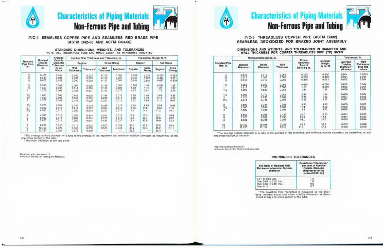
Characteristics of Piping MaterialsNon-Ferrous Pipe and Tubing
Characteristics of Piping MaterialsNon-Ferrous Pipe and Tubing
IVC-4 SEAMLESS COPPER PIPE AND SEAMLESS RED BRASS PIPE(ASTM B42-66 AND ASTM B43-66)
STANDARD DIMENSIONS, WEIGHTS, AND TOLERANCESNOTE-ALL TOLERANCES PLUS AND MINUS EXCEPT AS OTHERWISE INDICATED
Average Nominal Wall Thickness and Tolerance, in. Theoretical Weight Ib/ft
Standard Nominal Outside
PipeSize, Outside Diameter Regular Extra Strong Copper Red Brass
in. Diameter, Tolerance,"in. in.AII Wall Tolerance b Wall Toleranceb Regular Exira Extra
Minus Thickness Thickness Strong Regular Strong
Yo 0.405 0.004 0.062 0.004 0.100 0.006 0.259 0.371 0.253 0.363Yo 0.540 0.004 0.083 0.005 0.123 0.007 0.457 0.625 0.447 0.611Yo 0.675 0.005 0.090 0.005 0.127 0.007 0.641 0.847 0.627 0.829
Yo 0.840 0.005 0.107 0.006 0.149 0.008 0.955 1.25 0.934 1.23Y, 1.050 0.006 0.114 0.006 0.157 0.009 1.30 1.71 1.27 1.67
1 1.315 0.006 0.126 0.007 0.182 0.010 1.82 2.51 1.78 2.46
1}4 1.660 0.006 0.146 0.008 0.194 0.010 2.69 3.46 2.63 3.391Yi 1.900 0.006 0.150 0.008 0.203 0.011 3.20 4.19 3.13 4.102 2.375 0.008 0.156 0.009 0.221 0.012 4.22 5.80 4.12 5.67
2)1 2.875 0.008 0.187 0.010 0.280 0.015 6.12 8.85 5.99 8.663 3.500 0.010 0.219 0.012 0.304 0.016 8.75 11.8 8.56 11.63)/2 4.000 0.010 0.250 0.013 0.321 0.017 11.4 14.4 11.2 14.1
4 4.500 0.012 0.250 0.014 0.341 0.018 12.9 17.3 12.7 16.95 5.562 0.014 0.250 0.014 0.375 0.019 16.2 23.7 15.8 23.26 6.625 0.016 0.250 0.014 0.437 0.027 19.4 32.9 19.0 32.2
8 8.625 0.020 0.312 0.022 0.500 0.035 31.6 49.5 30.9 48.410 10.750 0.022 0.365 0.030 0.500 0.040 46.2 62.4 45.2 61.112 12.750 0.024 0.375 0.030 - - 56.5 - 55.3 -
a The average outside diameter of a tube is the average of the maximum and minimum outside diameters as determined at anyone cross section of the tube.
b Maximum deviation at anyone point.
Reprinted with permission ofAmerican Society for Testing and Materials
142
IVC-5 THREADLESS COPPER PIPE (ASTM B302)SEAMLESS, DEOXIDIZED FOR BRAZED JOINT ASSEMBLY
DIMENSIONS AND WEIGHTS, AND TOLERANCES IN DIAMETER ANDWALL THICKNESS FOR COPPER THREADLESS PIPE (TP) SIZES
Nominal Dimensions, in. Tolerances, in.Cross- Nominal
Standard Pipe Sectional Average Wall
Size,in. Outside Inside Wall Area ofWeight Outside Thickness,
Diameter Diameter Thickness Bore,sq in.Ib per It Diameter," plus and
all minus minus
Yo 0.540 0.410 0.065 0.132 0.376 0.004 0.0035Yo 0.675 0.545 0.065 0.233 0.483 0.004 0.004Yo 0.840 0.710 0.065 0.396 0.613 0.005 0.004
Y, 1.050 0.920 0.065 0.665 0.780 0.005 0.0041 1.315 1.185 0.065 1.10 0.989 0.005 0.00413{ 1.660 1.530 0.065 1.84 1.26 0.006 0.004
1}) 1.900 1.770 0.065 2.46 1.45 0.006 0.0042 2.375 2.245 0.065 3.96 1.83 0.007 0.0062X 2.875 2.745 0.065 5.92 2.22 0.007 0.006
3 3.500 3.334 0.083 8.73 3.45 0.008 0.0073X 4.000 3.810 0.095 11.4 4.52 0.008 0.0074 4.500 4.286 0.107 14.4 5.72 0.010 0.009
5 5.562 5.298 0.132 22.0 8.73 0.012 0.0106 6.625 6.309 0.158 31.3 12.4 0.014 0.0108 8.625 8.215 0.205 53.0 21.0 0.018 0.014
10 10.750 10.238 0.256 82.3 32.7 0.018 0.01612 12.750 12.124 0.313 115 47.4 0.D18 0.020
aThe average outside diameter of a tube is the average of the maximum and minimum outside diameters, as determined at anyone cross-section of the tube.
Reprinted with permission ofAmerican Society for Testing and Materials
ROUNDNESS TOLERANCES
Roundness Tolerances,atid, Ratio of Nominal Wall per cent of Nominal
Thickness to Nominal Outside Outside DiameterDiameter (Expressed to the
Nearest 0.001 in.)
0.01 to 0.03 inel. 1.5Over 0.03 to 0.05, incl. 1.0Over 0.05 to 0.10, incl. 0.8Over 0.10 0.7
a The deviation from roundness is measured as the differ-ence between major and minor outside diameters as deter-mined at anyone cross-section of the tube.
143
.......セ ..<z セ セ セ セ _ __

-Characteristics of Piping Materials
Non-Ferrous Pipe and TubingCharacteristics of Piping Materials
Non-Ferrous Pipe and TubingIVC-6 SEAMLESS COPPER WATER TUBE (ANSI H23.1-67)
PLUMBING AND FLUID CONVEYANCE TUBING
DIMENSIONS, WEIGHTS, AND TOLERANCES IN DIAMETER AND WALLTHICKNESS FOR STANDARD COPPER WATER TUBE SIZES
(ALL TOLERANCES IN THIS TABLE ARE PLUS AND MINUS EXCEPT AS OTHERWISE INDICATED)
Average Outside TheoreticalWeight,Diametera Nominal Wall Thickness and Tolerances, in.Tolerancein. Ib per ft
NominalStandard OutsideSize, in. Diameter, Type K Type L Type M
in.Annealed Drawn Type K Type L Type M
Wall Wall WallThickness tッャ・イ。ョ」・セ Thickness Toleranceb Thickness Toleranceb
y, 0.375 0.002 0.001 0.035 0.004 0.030 0.0035 . . 0.145 0.126 <
% 0.500 0.0025 0.001 0.049 0.004 0.035 0.0035 0.025 0.0025 0.269 0.198 0.145Y, 0.625 0.0025 0.001 0.049 0.004 0.040 0.0035 0.028 0.0025 0.344 0.285 0.204
% 0.750 0.0025 0.001 0.049 0.004 0.042 0.0035 . . 0.418 0.362 .% 0.875 0.003 0.001 0.065 0.0045 0.045 0.004 0.032 0.003 0.641 0.455 0.328
1 1.125 0.0035 0.0015 0.065 0.0045 0.050 0.004 0.035 0.0035 0.839 0.655 0.465lY4 1.375 0.004 0.0015 0.065 0.0045 0.055 0.0045 0.042 0.0035 1.04 0.884 0.682
1}1 1.625 0.0045 0.002 0.072 0.005 0.060 0.0045 0.049 0.004 1.36 1.14 0.9402 2.125 0.005 0.002 0.083 0.007 0.070 0.006 0.058 0.006 2.06 1.75 1.462}2 2.625 0.005 0.002 0.095 0.007 0.080 0.006 0.065 0.006 2.93 2.48 2.033 3.125 0.005 0.002 0.109 0.007 0.090 0.007 0.072 0.006 4.00 3.33 2.68
3}2 3.625 0.005 0.002 0.120 0.008 0.100 0.007 0.083 0.007 5.12 4.29 3.584 4.125 0.005 0.002 0.134 0.010 O.llO 0.009 0.095 0.009 6.51 5.38 4.665 5.125 0.005 0.002 0.160 0.010 0.125 0.010 0.109 0.009 9.67 7.61 6.666 6.125 0.005 0.002 0.192 0.012 0.140 O.Oll 0.122 0.010 13.9 10.2 8.92
8 8.125 0.006 +0.002 0.271 0.016 0.200 0.014 0.170 0.014 25.9 19.3 16.5-0.004
10 10.125 0.008 +0.002 0.338 0.018 0.250 0.016 0.212 0.015 40.3 30.1 25.6-0.006
12 12.125 0.008 +0.002 0.405 0.020 0.280 0.Ql8 0.254 0.016 57.8 40.4 36.7-0.006
"The averag.e outside diameter of a tube is the average of the maximum and minimum outside diameter, as determined at anyone cross section of the tube.
b Maximum deviation at anyone point.e Indicates that the material is not generally available or that no tolerance has been established.
Reprinted with permission ofAmerican Society for Testing and Materials
144
e
IVC-7 WROUGHT SEAMLESS COPPER AND COPPER ALLOY TUBE(ANSI 23.4-67)
APPLICABLE PRODUCTS, UNLESS OTHERWISE SPECIFIED:
Title of Product SpecificationASTM
Designation"Seamless Copper Tube, BrightAnnealed B 68
Seamless Copper Tube B 75Seamless Brass Tube B 135Seamless Copper-Nickel Pipe andTube B 466
a These designations refer to the latest issue of the respec-tive specification which appears in this publication.
Reprinted with permission ofAmerican Society for Testing and Materials
145

-Characteristics of Piping Materials
Non-Ferrous Pipe and TubingCharacteristics of' Piping Materials
Non-Ferrous Pipe and TubingIVC·7 WROUGHT SEAMLESS COPPER AND COPPER ALLOY TUBE
(ANSI 23.4-67)IVC-7 WROUGHT SEAMLESS COPPER AND COPPER ALLOY TUBE
(ANSI 23.4-67)CONTINUED
_When round tube is ordered by outside and inside diameters, the maximum plus and minus deviation of the wall thickness fromthe nominal at any point shall not exceed the values given in the table by more than 50 percent.
Outside Diameter, in.- (mm)
Wall Thickness, in. (mm) lI", oカ・イセ Over X Over 1 Over2 Over 4 Over 7(0.792) to (3.18) \0 (15.9) to (25.4) to (50.8) \0 (102) to (213) \0
Yo (3.18), % (15.9), 1 (25.4), 2 (50.8), 4 (102), 7 (213), 10 (254),
incl incl incl incl incl incl incl
Under 0.018 (0.457) 0.002 0.001 0.0015 0.002 - - -(0.051 ) (0.025 ) (0.038 ) (0.051 ) - - -
0.018 (0.457), incl to 0.025 (0.635) 0.003 0.002 0.002 0.0025 - - -(0.076) (0.051 ) (0.051 ) (0.064 ) - - -
0.025 (0.635), incl to 0.035 (0.889) 0.003 0.0025 0.0025 0.003 0.004 - -(0.076) (0.064 ) (0.064 ) (0.076 ) (0.10 ) - -
0.035 (0.889), incl to 0.058 (1.47) 0.003 0.003 0.0035 0.0035 0.005 0.007 -(0.076) (0.076 ) (0.089 ) (O.089 ) (0.13 ) (0.18 ) -
0.058 (1.47), incl to 0.083 (2.11) 0.0035 0.004 0.004 0.006 0.008 0.010(0.089 ) (0.10 ) (0.10 ) (0.15 ) (O.20 ) {O.25 }
0.083 (2.11), incl to 0.120 (3.03) 0.004 0.005 0.005 0.007 0.009 0.011{O.10 } (0.13 ) (0.13 ) (0.18 ) (0.23 ) (0.28 )
0.120 (3.03), incl to 0.165 (4.19) 0.005 0.006 0.006 0.008 0.010 0.012(0.13 ) (0.15 ) (0.15 ) (O.20 ) (0.25 ) (0.30 )
0.165 (4.19), inclto 0.220 (5.59) - 0.007 0.0075 0.008 0.010 0.012 0.014
- (0.18 ) (0.19 ) (0.20 ) (0.25 ) (0.30 ) (0.36 )
0.220 (5.59), incl to 0.284 (7.21) - - 0.009 0.010 0.012 0.014 0.016- - (0.23 ) {O.25 } (0.30 ) (0.36 ) {0.41 }
0.284 (7.21), incl to 0.380 (9.65) - - 0.011 0.012 0.014 0.016 0.018
- - (0.28 ) (0.30 ) (0.36 ) (0.41 ) (0.46 )
0.380 (9.65) and over - - - 5 per- 5 per- 6 per- 6 per-- - - cent cent cent cent
WALL THICKNESS TOLERANCES FOR COPPER ANDCOPPER·ALLOY TUBE
{Applicable to Specifications B 68, B 75, and B 135}
NOTE-Maximum Deviation at Any Point: The following tolerances are plus and minus; if tolerances all plus or all minus aredesired, double the values given.
[X indicates the preferred sizes]
PREFERRED SIZES OF ROUND SEAMLESS COPPER AND COPPER·ALLOY TUBE','
APPLICABLE TO ASTM DESIGNATIONS B 75 AND B 135
Wall Thickness, in. (mm)
Outside ;; S " 0; in 0;-Diameter, "' '" 0 0 '" N«! s ;; in ;:- ;; .. " .. in N N ;::
セin. (mm) 0O! ","l ",": 0"1 B G セ oq ",O! B G セ ",'": 0"1 セ '" .... '" '" "' Nセッ セッ セッ g!2 ",0 ",0 ... セ ... セ '" セ <0'" 0'" e e :!. e !S e l:-0- 0- 0- 0- 0- 0- 0- 0-0- セ M0 0 0 0 0 0 0 0 0 0 0 セ ,;; セ セ ;;;: ;;!. :>': ;;!.
Yo (3.18) X X X X X X X - - - - - - - - - - - -li". (4.78) X X X X X X X X - - - - - - - - - - -% (6.35) - - X X X X X X X X - - - - - - - - -)(. (7.92) - - X X X X X X X X X - - - - - - - -% (9.52) - - X X X X X X X X X X - - - - - - -V, (12.7) - - X X X X X X X X X X X - - - - - -% (15.9) - - X X X X X X X X X X X - - - - - -%(19.1) - - X X X X X X X X X X X - - - - - -Yo (22.3) - - X X X X X X X X X X X X - - - - -
1 (25.4) - - - X X X X X X X X X X X X - -1% (31.8)
- -- - - X X X X X X X X X X X X X - - -
1V, (38.1) - - - X X X X X X X X X X X X X X - -1% (44.4) - - - X X X X X X X X X X X X X X - -2 (50.8) - - - - X X X X X X X X X X X X X X2% (57.2)
-- - - - X X X X X X X X X X X X X X -
2V, (63.5) - - - - X X X X X X X X X X X X X X X2% (69.8) - - - - X X X X X X X X X X X X X X X3 (76.2) - - - - - X X X X X X X X X X X X X X3V, (88.9) - - - - - X X X X X X X X X X X X X X4 (102) - - - - - - X X X X X X X X X X X X X4V,(114) - - - - - - X X X X X X X X X X X X X5 (127) - - - - - - - X X X X X X X X X X X X5V, (140) - - - - - - - X X X X X X X X X X X X6 (152) - - - - - - - - X X X X X X X X X X X7 (178) - - - - - - - - X X X X X X X X X X X8 (203) - - - - - - - - - X X X X X X X X X X9 (229) - - - - - - - - - X X X X X X X X X X
10 (254) - - - - - - - - - - X X X X X X X X X11 (279) - - - - - - - - - - X X X X X X X X X12 (305) - - - - - - - - - - - X X X X X X X X
• In conformance with the Simplified Practice Recommendations R 235-48 for Copper and Copper-Alloy Round Seamless Tubeissued by the U.S. Department of Commerce.
• This tube is not necessarily available in all alloys in the full range of sizes shown.
Reprinted with permission 01American Society for Testing and Materials
Reprinted with permission 01American Society lor Testing and Materials
146 147
• s
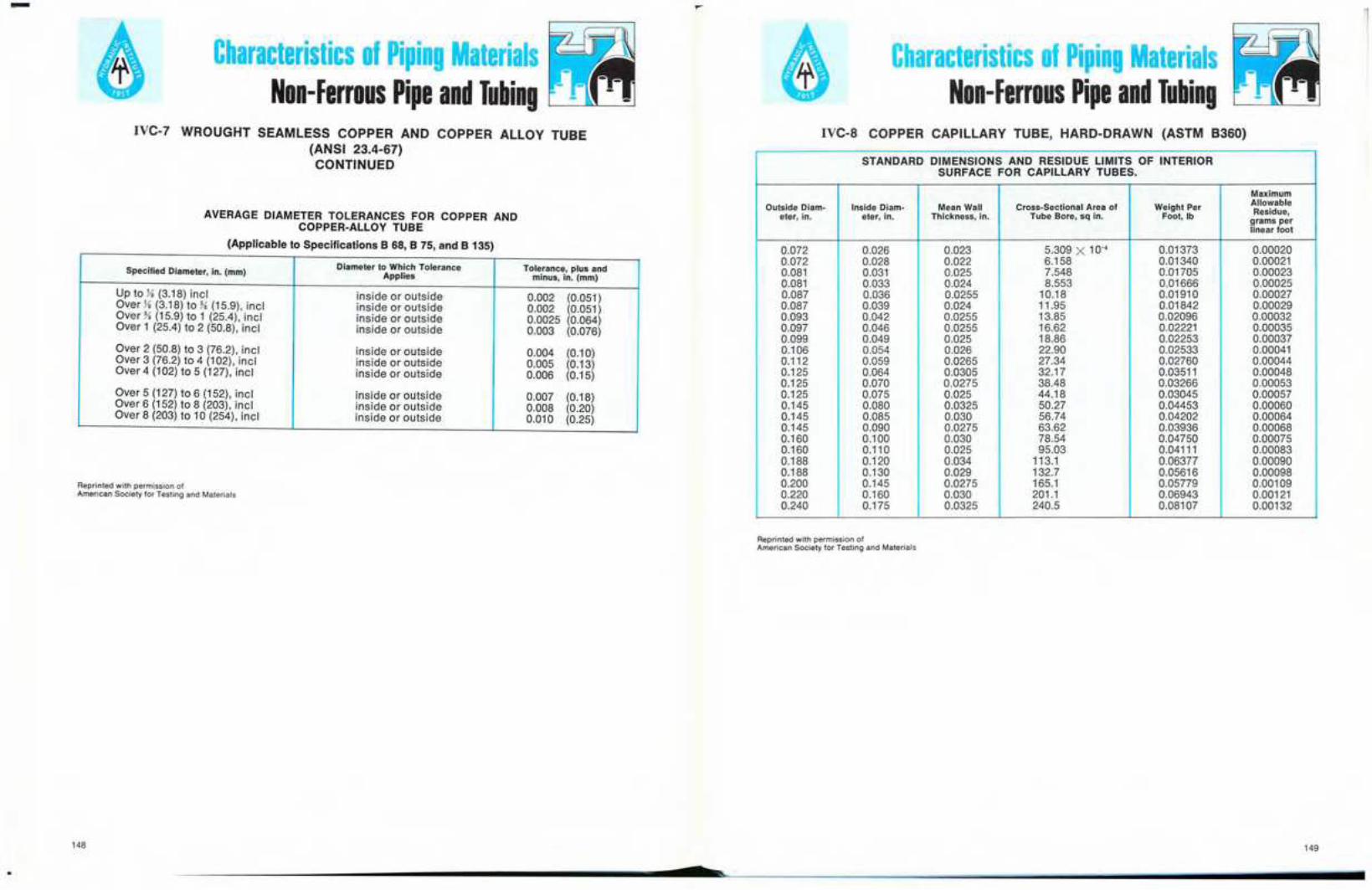
-Characteristics of Piping Materials
Non-Ferrous Pipe and TubingCharacteristics of Piping Materials
Non-Ferrous Pipe and TubingIVC-7 WROUGHT SEAMLESS COPPER AND COPPER ALLOY TUBE
(ANSI 23.4-67)CONTINUED
AVERAGE DIAMETER TOLERANCES FOR COPPER ANDCOPPER-ALLOY TUBE
(Applicable to Specifications B 68, B 75, and B 135)
Specified Diameter, in. (mm) Diameter to Which Tolerance Tolerance, plus andApplies minus, in. (mm)
Up to Yo (3.18) incl inside or outside 0.002 (0.051)Over Yo (3.18) to % (15.9). incl inside or outside 0.002 (0.051)Over %{15.9} to 1 {25.4}, incl inside or outside 0.0025 (O.064)Over 1 (25.4) to 2 (50.8). inc I inside or outside 0.003 (0.076)
Over 2 (50.8) to 3 (76.2). incl inside or outside 0.004 (0.10)Over 3 (76.2) to 4 (102), incl inside or outside 0.005 (0.13)Over 4 (102) to 5 (127), incl inside or outside 0.006 (0.15)
Over 5 (127) to 6 (152). incl inside or outside 0.007 (0.18)Over 6 (152) to 8 (203), incl inside or outside 0.008 (0.20)Over 8 (203) to 10 (254), inc I inside or outside 0.010 (O.25)
Reprinted with permission ofAmerican Society for Testing and Materials
148
IVC-8 COPPER CAPILLARY TUBE, HARD-DRAWN (ASTM B360)
STANDARD DIMENSIONS AND RESIDUE LIMITS OF INTERIORSURFACE FOR CAPILLARY TUBES.
Maximum
Outside Diam- Inside Diam. Mean Wall Cross-Sectional Area of Weight Per AllowableResidue,eter, in. eter, in. Thickness, in. Tube Bore, sq in. Foot, Ib grams per
linear foot
0.072 0.026 0.023 5.309 X 10-' 0.01373 0.000200.072 0.028 0.022 6.158 0.01340 0.000210.081 0.031 0.025 7.548 0.01705 0.000230.081 0.033 0.024 8.553 0.01666 0.000250.087 0.036 0.0255 10.18 0.01910 0.000270.087 0.039 0.024 11.95 0.01842 0.000290.093 0.042 0.0255 13.85 0.02096 0.000320.097 0.046 0.0255 16.62 0.02221 0.000350.099 0.049 0.025 18.86 0.02253 0.000370.106 0.054 0.026 22.90 0.02533 0.000410.112 0.059 0.0265 27.34 0.02760 0.000440.125 0.064 0.0305 32.17 0.03511 0.000480.125 0.070 0.0275 38.48 0.03266 0.000530.125 0.075 0.025 44.18 0.03045 0.000570.145 0.080 0.0325 50.27 0.04453 0.000600.145 0.085 0.030 56.74 0.04202 0.000640.145 0.090 0.0275 63.62 0.03936 0.000680.160 0.100 0.030 78.54 0.04750 0.000750.160 0.110 0.025 95.03 0.04111 0.000830.188 0.120 0.034 113.1 0.06377 0.000900.188 0.130 0.029 132.7 0.05616 0.000980.200 0.145 0.0275 165.1 0.05779 0.001090.220 0.160 0.030 201.1 0.06943 0.001210.240 0.175 0.0325 240.5 0.08107 0.00132
Reprinted with permission ofAmerican Society for Testing and Materials
149
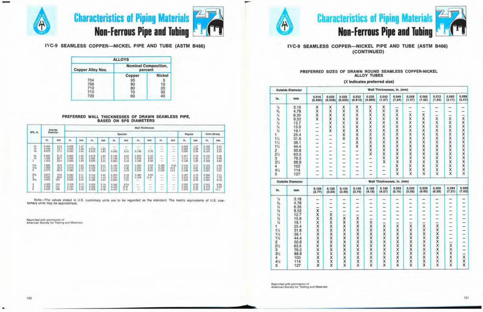
-Characteristics of Piping Materials
Non-Ferrous Pipe and TubingCharacteristics of Piping Materials
Non-Ferrous Pipe and TubingIVC-9 SEAMLESS COPPER-NICKEL PIPE AND TUBE (ASTM B466)
ALLOYS
Nominal Composition,Copper Alloy Nos. percent
Copper Nickel704 95 5706 90 10710 80 20715 70 30720 60 40
PREFERRED WALL THICKNESSES OF DRAWN SEAMLESS PIPE,BASED ON SPS DIAMETERS
Wall ThicknessesOutside
SPS,in. DiameterSpecials Regular Elttra Strong
in. mm in. mm in. mm in. mm in. mm in. mm in. mm in. mm
'10 0.405 10.3 0.058 1.47 - - - - - - - - 0.062 1.57 0,100 2.54V. 0.540 13.7 0.065 1.65 0.072 1.83 - - - - - - 0.082 2.08 0.123 3.12
'" 0.675 17.1 0.065 1.65 0.072 1.83 0.095 2.41 0.148 3.76 - - 0.090 2.29 0.127 3.23
'h 0.840 21.3 0.065 1.65 0.072 1.83 0.120 3.03 0.203 5.16 - - 0.107 2.72 0.149 3.78¥. 1.050 26.7 0.065 1.65 0.083 2.11 0.148 3.76 0.238 6.05 - - 0.114 2.90 0.157 3.99
1 1.315 33.4 0,065 1.65 0.095 2.41 0.203 5.16 0.340 8.64 - - 0.126 3.20 0.182 4.62
IV< 1.660 42.2 0.072 1.83 0.095 2.41 0.120 3.03 0.220 5.59 0.380 9.65 0.146 3.71 0.194 4.93lV, 1.900 48.3 0.072 1.83 0.109 2.77 0.134 3.40 0.250 6.35 0.425 10.8 0.150 3.81 0.203 5.162 2.375 60.3 0.083 2.11 0.120 3.03 0.165 4.19 0.340 8.64 0.520 13.2 0.156 3.96 0.221 5.61
2'n 2.875 73.0 0.083 2.11 0.134 3.40 0.203 5.16 0.380 9.65 - - 0.187 4.75 0.280 7.113 3.500 88.9 0.095 2.41 0.165 4.19 0.250 6.35 0.458 11.6 - - 0.219 5.56 0.304 7.7231/2 4.000 102 0.095 2.41 0.180 4.57 0.284 7.21 - - - - 0.250 6.35 0.321 8.15, 4.500 !l' 0.109 2.77 0.203 5.16 0.340 8.64 - - - - 0.250 6.35 0.341 8.665 5.562 '" 0.125 3.18 0.220 5.59 0.425 10.8 - - - - 0.250 6.35 0.375 9.526 6.625 168 0.134 3.40 0.259 6.58 0.457 11.6 - - - - 0.250 6.35 0.437 11.1
Note-The values stated in U.S. customary units are to be regarded as the standard. The metric equivalents of U.S, cus-tomary units may be approximate.
Reprinted with permission ofAmerican Society for Testing and Materials
150
$
IVC-9 SEAMLESS COPPER-NICKEL PIPE AND TUBE (ASTM B466)(CONTINUED)
PREFERRED SIZES OF DRAWN ROUND SEAMLESS COPPER-NICKELALLOY TUBES
(X indicates preferred size)
Outside Diameter Wall Thicknesses, In. (mm)
in. 0.016 0.020 0.025 0.032 0.035 0.042 0.049 0.058 0.065 0.072 0.083 0.095mm (0.406) (0.508) (0.635) (0.813) (0.889) (1.07) (1.24) (1.47) (1.65) (1.83) (2.11) (2.41
Yo 3.18 X X X X X X - - - - - -l1, 4.78 X X X X X X X - - - - -% 6.35 X X X X X X X X X - - -% 9.52 X X X X X X X X X X X XJ1 12.7 - X X X X X X X X X X X% 15.9 - X X X X X X X X X X X% 19.1 - X X X X X X X X X X X
1 25.4 - - X X X X X X X X X XQセ 31.8 - - X X X X X X X X X X171 38.1 - - - X X X X X X X X X1% 44.4 - - - X X X X X X X X X2 50.8 - - - - X X X X X X X X271 63.5 - - - - X X X X X X X X3 76.2 - - - - - X X X X X X X3J1 88.9 - - - - - X X X X X X X4 102 - - - - - - X X X X X X4X 114 - - - - - - X X X X X X5 127 - - - - - - X X X X X X
Outside Diameter Wall Thicknesses, in. (mm)
in. 0.109 0.120 0.134 0.148 0.165 0.180 0.203 0.220 0.238 0.259 0.284 0.30.0mm (2.77) (3.03) (3.40) (3.76) (4.19) (4.57) (5.16) (5.59) (6.05) (6.58) (7.21) (7.62
Yo 3.18 - - - - - - - - - - - -l1, 4.78 - - - - - - - - - - - -% 6.35 - - - - - - - - - - - -% 9.52 X - - - - - - - - - - -J1 12.7 X X - - - - - - - - - -% 15.9 X X X X - - - - - - - -% 19.1 X X X X X - - - - - - -
1 25.4 X X X X X X X X X X - -1% 31.8 X X X X X X X X X X - -172 38.1 X X X X X X X X X X - -1% 44.4 X X X X X X X X X X - -2 50.8 X X X X X X X X X X - -2J1 63.5 X X X X X X X X X X X -3 76.2 X X X X X X X X X X X -3J1 88.9 X X X X X X X X X X X -4 103 X X X X X X X X X X X X4J1 114 X X X X X X X X X X X X5 127 X X X X X X X X X X X X
Reprinted with permission ofAmerican Society for Testing and Materials
151
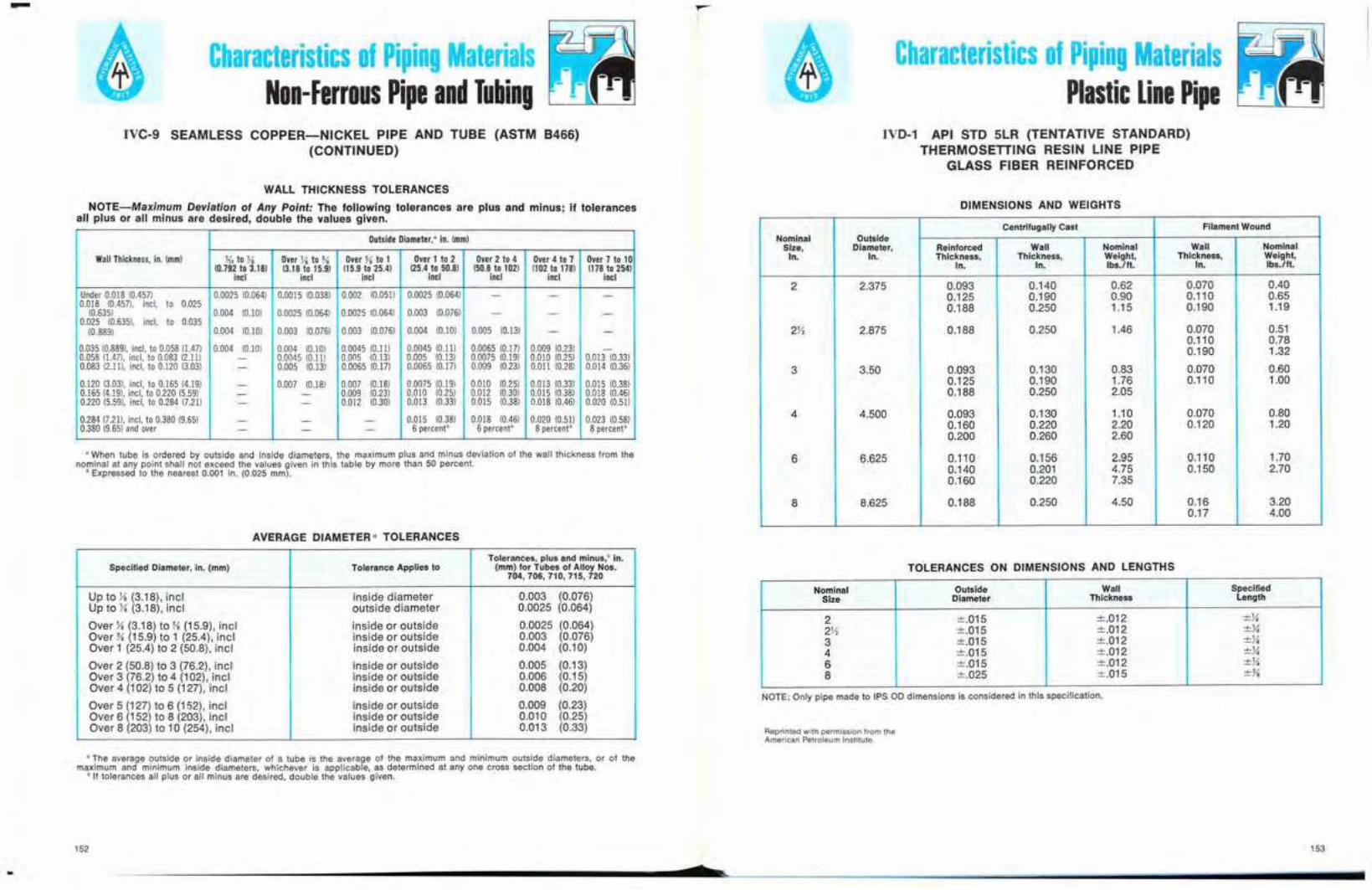
-Characteristics of Piping Materials
Non-Ferrous Pipe and TubingCharacteristics of Piping Materials
Plastic Line PipeIVC·9 SEAMLESS COPPER-NICKEL PIPE AND TUBE (ASTM B466)
(CONTINUED)
WALL THICKNESS TOLERANCES
NOTE-Maximum Deviation of Any Point: The tollowing tolerances are plus and minus; if tolerancesall plus or all minus are desired, double the values given.
Outside Diameter,- in. (mm)
Wall Thickness,in. (mm) J{2 to X Over X to % Over % to 1 Overlto2 Over 2 to 4 Over 4 to 7 Over 7 to 10(0.792 to 3.18) (3.18 to 15.9) (15.9 to 25.4) 125.4to 50.8) (50.8 to 102) (102 to 178) (178 to 254)
incl inel incl incl incl incI incl
Under 0.018 10.4571 0.0025 10.0641 0.0015 10.0381 0.002 10.0511 0.0025 (0.064) - - -0.018 10.457). incl, to 0.025
(0.6351 0.004 10.101 0.0025 10.0641 0.0025 10.0641 0.003 10.0761 - - -0.025 10.635). incl, to 0.035
(0.8891 0.004 10.101 0.003 10.0761 0.003 10.076) 0.004 10.101 0.005 10.13) - -
0.03510.889). incl. 10 0.058(1.471 0.004 10.101 0.004 (0.101 0.0045 10.111 0.0045 10.111 0.0065 10.171 0.009 (0.231 -0.058 (1.471. incl. to 0.083 12.111 - 0.0045 10.111 0.005 (0.131 0.005 10.131 0.0075 10.191 0.010 10.25) 0.013 10.33)0.08312.111,incl. to 0.12013.031 - 0.005 (0.131 0.0065 10.171 0.0065 10.171 0.009 10.23) 0.011 10.281 0.014 10.361
0.120 13.031. incl, to 0.165 14.191 - 0.007 10.181 0.007 10.181 0.0075 10.191 0.010 10.251 0.013 10.331 0.015 10.3810.16514.191.incl. to 0.220 15.591 - - 0.009 (0.231 0.010 10.251 0.012 10.301 0.Dl5 10.381 0.Dl8 10.4610.220 15.591. incl, to 0.284 17.211 - - 0.012 10.301 0.013 10.331 0.Dl5 10.381 0.Dl8 10.461 0.020 (0.511
0.28417.211,incl. to 0.38019.651 - - - 0.015 10381 0.Dl8 10.461 0.020 10.511 0.023 10.5810.380(9.651and over - - - 6 percent b 6 ー・イ」・ョエセ 8 percentb 8percentb
• When tube is ordered by outside and inside diameters, the maximum plus and minus deviation of the wall thickness from thenominal at any point shall not exceed the values given in this table by more than 50 percent.
• Expressed to the nearest 0.001 in. (0.025 mm).
AVERAGE DIAMETER" TOLERANCES
Tolerances,plus and minus,·in.Specified Diameter, in. (mm) Tolerance Applies to (mm) for Tubes of Alloy Nos.
704, 706, 710, 715,720
Up to Yo (3.18), incl inside diameter 0.003 (0.076)Up to Yo (3.18), incl outside diameter 0.0025 (0.064)
Over Yo (3.18) to Yo (15.9), incl inside or outside 0.0025 (0.064)Over Yo (15.9) to 1 (25.4), incl inside or outside 0.003 (0.076)Over 1 (2504) to 2 (50.8), incl inside or outside 0.004 (0.10)
Over 2 (50.8) to 3 (76.2), incl inside or outside 0.005 (0.13)Over 3 (76.2) to 4 (102), incl inside or outside 0.006 (0.15)Over 4 (102) to 5 (127), incl inside or outside 0.008 (0.20)
Over 5 (127) to 6 (152), incl inside or outside 0.009 (0.23)Over 6 (152) to 8 (203), incl inside or outside 0.010 (0.25)Over 8 (203) to 10 (254), incl inside or outside 0.013 (0.33)
• The average outside or inside diameter of a tube is the average of the maximum and minimum outside diameters, or of themaximum and minimum inside diameters, whichever is applicable, as determined at anyone cross section of the tube.
• If tolerances all plus or all minus are desired, double the values given.
152
IVD·1 API STD 5LR (TENTATIVE STANDARD)THERMOSETTING RESIN LINE PIPE
GLASS FIBER REINFORCED
DIMENSIONS AND WEIGHTS
Centrifugally Cast Filament WoundNominal Outside
Size, Diameter, Reinforced Wan Nominal Wan NominalIn. In. Thickness, Thickness, Weight, Thickness, Weight,
In. In. Ibs.lft. In. Ibs.lft.
2 2.375 0.093 0.140 0.62 0.070 00400.125 0.190 0.90 0.110 0.650.188 0.250 1.15 0.190 1.19
2X 2.875 0.188 0.250 1046 0.070 0.510.110 0.780.190 1.32
3 3.50 0.093 0.130 0.83 0.070 0.600.125 0.190 1.76 0.110 1.000.188 0.250 2.05
4 4.500 0.093 0.130 1.10 0.070 0.800.160 0.220 2.20 0.120 1.200.200 0.260 2.60
6 6.625 0.110 0.156 2.95 0.110 1.700.140 0.201 4.75 0.150 2.700.160 0.220 7.35
8 8.625 0.188 0.250 4.50 0.16 3.200.17 4.00
TOLERANCES ON DIMENSIONS AND LENGTHS
Nominal Outside Wan SpecifiedSize Diameter Thickness Length
2 ±.015 ±.012 ±liR セ ±.015 ±.012 ±X3 ±.015 ±.012 ±X4 ±.015 ±.012 ±X6 ±.015 ±.012 ±X8 ±.025 ±.015 ᄆ セ
NOTE: Only pipe made to IPS 00 dimensions is considered in this specification.
Reprinted with permission from theAmerican Petroleum Institute.
153

-Characteristics of Piping Materials
Plastic Line PipeCharacteristics of Piping Materials
Flanges
TEMPLATES FOR DRILLING STEEL FLANGES AND FLANGED FITTINGS
POINT HEIGHT (NOTE 2)
STUD BOLT WITH NUTS
MACHINE BOLT WITH NUT
FLANGE
FLANGE FITTING
IVE-1 150-LB STEEL PIPE FLANGES AND FLANGED FITTINGS
Drilling 1Length of Bolts 3
Outside L
Nominal Diameter Stud Bolls 2 Machine BoltsPipe of Diameter Diameter Number DiameterSize Flange of of of of
0 Boll Bolt Bolts Bolts K6- ln. Ring J.{6a1n.Circle Holes Raised Face Joint Raised Face
V, 3V, 2% % 4 V, 2Y2 - 2% 3% 2% % 4 V, 2Y2 - 2Y4
1 4% 3Ya % 4 V, 23/4 3% 2%1% 4% 31'2 % 4 V, 23/4 3% 2Y21V, 5 3% % 4 V, 3 3Y2 2Y2
2 6 4% % 4 % 3% 33/4 23/42V, 7 5V, % 4 % 3Y2 4 33 7V, 6 % 4 % 33/4 4% 3Y431'2 81'2 7 % 8 % 33/4 4Y4 3Y44 9 7J1 % 8 % 33/4 4Y4 3Y4
5 10 8V, % 8 % 4 4Y2 3Y46 11 91'2 % 8 % 4 4Y2 3Y2
8 13V, 11% % 8 % 4Y4 43/4 3Y2
10 16 14% 1 12 % 43/4 5Y4 4
12 19 17 1 12 % 43/4 5'/4 4Y4
14 21 18% 1Ya 12 1 5Y4 53/4 4Y2
16 23V, 21 % 1Ya 16 1 5Y2 6 43/.
18 25 22% 1% 16 1X 6 6Y2 5
20 27V, 25 1% 20 1X 6Y4 63/4 5Y2
24 32 29V, 1% 20 1% 7 7Y2 6
DIMENSIONS, WEIGHTS AND TOLERANCES
IVD-2 API STD 5LP (TENTATIVE STANDARDS)THERMOPLASTIC LINE PIPE
EXTRUDED POLYVINYL CHLORIDE (PVC)
Reprinted with permission from theAmerican Petroleum Institute.
Nominal Outside Dia. & Minimum Wall Tolerance, Minimum WeightSize, In. Tolerance, In. Thickness, In. In. Lb/l00 ft.
2 2.375± 0.030 0.073 +0.020 33.52.375± 0.030 0.091 +0.020 41.02.375± 0.030 0.113 +0.020 50.82.375± 0.012 0.154 +0.020 67.62.375± 0.012 0.176 +0.021 77.0
R セ 2.875± 0.030 0.088 +0.020 48.72.875± 0.030 0.110 +0.020 60.42.875± 0.030 0.137 +0.020 74.22.875± 0.015 0.203 +0.026 107.02.875± 0.015 0.213 +0.026 113.0
3 3.500± 0.030 0.108 +0.020 72.83.500± 0.030 0.135 +0.020 90.03.500± 0.030 0.167 +0.020 110.03.500± 0.015 0.216 +0.026 140.03.500± 0.015 0.259 +0.031 166.0
3V, 4.000± 0.050 0.123 +0.020 97.04.000± 0.050 0.154 +0.020 118.04.000± 0.050 0.190 +0.023 144.04.000± 0.015 0.296 +0.036 217.0
4 4.500± 0.050 0.110 +0.020 98.04.500± 0.050 0.138 +0.020 119.64.500± 0.050 0.173 +0.021 148.04.500± 0.050 0.214 +0.026 182.04.500± 0.015 0.237 +0.026 200.04.500± 0.015 0.333 +0.040 275.0
5 5.563± 0.050 0.136 +0.020 148.05.563± 0.050 0.171 +0.021 183.05.563± 0.050 0.214 +0.027 228.0
6 6.625± 0.050 0.162 +0.020 208.06.625± 0.050 0.204 +0.024 260.06.625± 0.050 0.255 +0.031 322.0
8 8.625± 0.075 0.210 +0.025 348.08.625± 0.075 0.265 +0.032 432.0
All dimensions given in inches.1 Bolt holes straddle the center lines.2 Length of stud-bolts do not include the height of the points.3 Bolt lengths not shown in table are determined in accordance with ANSI B16.5-1968.
Reprinted with permissionfrom the American Societyof Mechanical Engineers,N.Y.. N.Y.
154
•155
-Characteristics of Piping Materials
FlangesCharacteristics of Piping Materials
FlangesIVE-1 300-LB STEEL PIPE FLANGES AND FLANGED FITTINGS IVE-1 400-LB STEEL PIPE FLANGES AND FLANGED FITTINGS
FLANGE
!! . ャセ
MACHINE BOLT WITH NUT
FLANGE
, .! .
POINT HEIGHT (NOTE 2)
STUD BOLT WITH NUTSFLANGE FITTING
POINT HEIGHT (NOTE 2)
STUD BOLT WITH NUTSFLANGE FITTING
TEMPLATES FOR DRILLING STEEL FLANGES AND FLANGED FITTINGS TEMPLATES FOR DRilLING STEEL FLANGES AND FLANGED FITTINGS
Drilling ILength of Bolts 3
Outside LNominal Diameter
Pipe of Diameter Diameter Stud Bolts 2 Machine BoltsSize Flange of of Number Diameter
0 Bolt Bolt of ofJ{6·ln. Ring K6- ln.
Circle Holes Bolts Bolts Raised Face Joint Raised Face
y, 3% 2% % 4 Y, 2Y, 3 2% 4% 3X % 4 % 2% 3X 2}2
1 4% 3X % 4 % 3 3Y, 2711X 5X 3% % 4 % 3 3X 2%1X 6Y. 471 % 4 % 3}2 4 3
2 6X 5 % 8 % 3M 4 32Yi 7X 5% % 8 % 3% 4}2 3%3 8Y. Vセ % 8 % 4 4% 3X3X 9 7X % 8 % 4X 5 3%4 10 7% % 8 % 4X 5 3%
5 11 9Y. % 8 % 4Y, 5X 46 12Y, 10% % 12 % 4% 571 4X8 15 13 1 12 % 5X 6 4%
10 17Y, 15Y. 1X 16 1 6 6% 5%12 20Y, 17% 1% 16 1Y. 6X 7X 5%
14 23 20% 1X 20 1X 6% 771 616 25Y, 22Y, 1% 20 1X 7X 8 6X18 28 24% 1% 24 1X ?Yo ax 6%20 30Y, 27 1% 24 1M 8 8% 724 36 32 1% 24 1Y, 9 10 7%
Drilling 1Length 2, 3 of Stud Bolls
L
Nominal OutsideMale&DiameterPipe of Flange Diameter Diameter Number Diameter X-In. Female RingSize 0 of of of of Raised also JointBolt Bolt Bolts Belts Face Tongue &
Circle Holes Groove
Y,%
11%
Use 600-lb dimensions in these sizes.1)1
22Y,33Y,
4 10 TYs 1 8 % 514 5 5Y,5 11 914 1 8 % 5Y, 514 5%6 12Y, 10% 1 12 % 5% 5X 68 15 13 1X 12 1 6X 6Y. 6%
10 1m 15Y. 114 16 1X 714 7 7Y,12 20Y, 17% 1% 16 114 7Y. 7X 8
14 23 20Y. 1% 20 114 8 7% 8%16 25Y, 22Y, 1X 20 1% 8X 8% 8%18 28 24% 1X 24 1% 8% 8X 920 30Y, 27 1% 24 1X 9X 9X 9%24 36 32 Q セ 24 1% 10Y, 10% 11
All dimensions given in inches., Bolt holes straddle the center lines.2 Length of stud-bolts do not include the height of the points.J Bolt lengths not shown in table are determined in accordance with ANSI 816.5-1968.
Reprinted with permissionfrom the American Societyof Mechanical Engineers.N.Y., N.Y.
All dimensions given in inches.1 Bolt holes straddle the center lines.2 Length of stud-bolts do not include the height of the points.3 Bolt lengths not shown in table are determined in accordance with ANSI B16.5-1968.
Reprinted with permISSionfrom the American Societyof Mechanical Engineers,N.Y., N.Y.
10-
156
•157
-Characteristics of Piping Materials
FlangesCharacteristics of Piping Materials
FlangesIVE-1 600-LB STEEL PIPE FLANGES AND FLANGED FITTINGS IVE-1 900-LB STEEL PIPE FLANGES AND FLANGED FITTINGS
FLANGEFLANGE
POINT HEIGHT (NOTE 2)
STUD BOLT WITH NUTSFLANGE FITTINGPOINT HEIGHT (NOTE 2)
STUD BOLT WITH NUTSFLANGE FITTING
.. 0
TEMPLATES FOR DRILLING STEEL FLANGES AND FLANGED FITTINGSTEMPLATES FOR DRILLING STEEL FLANGES AND FLANGED FITTINGS
Drilling 1Length 2, 3 of Stud Bolts
L
Nominal Outside
Pipe DiameterDiameter Diameter Male &
Size of Flange of of Number Diameter セ セ ャ ョ N Female0 Bolt Bolt of of Raised also Ring
Circle Holes Bolts Bolts Face Tongue & JointGroove
y, 3% 2% % 4 Y, 3 2% 3% 4% 3)'{ % 4 % 3X 3 3Y.
1 4% 3!1 % 4 % Sセ 3X 3Y,1J4 5Y.i Sセ % 4 % 3% 3Y, 3%1Y, 6Y. 4Y, % 4 % 4 3% 4
2 6Y, 5 % a % 4 3% 4Y.2Y2 7!1 5% % a % 4!1 4Y. 4%3 8X 6% % a % 4% 4Y, 53Yi 9 7Yt. 1 a % 5Y.l 5 5Yi4 10% 871 1 a % 5!1 5Y. 5%
5 13 10Y, 1Y. a 1 6Y. 6 6Y,6 14 11Y, 1X 12 1 6!1 6X 6%a 16Y, 13% 1X 12 1Y. 7Yi 7Y. 7%
10 20 17 1% 16 1X ax a ay,12 22 19Y. 1% 20 1Y. 871 ay. a%
14 23% 20% 1Yi 20 1% 9 8% 9Y.16 27 23% 1% 20 1Yi 9% 9Y, 101a 29Y. 25% 1% 20 1% 10Y, 10Y. 10%20 32 2ay, 1% 24 1% 11Y. 11 11Y,24 37 33 2 24 1% 12% 12Y, 13Y.
Drilling 1Length 2, 3 of Stud Bolts
L
NominalOutsideDiameter Male &
Pipe of FlangeDiameter Diameter Number Diameter X-In. Female
Size 0of of of of Raised also
Ring
Boll Bolt Bolts Bolts Face Tongue &Joint
Circle Holes Groove
Y,%
11Y. Use 1500-lbdimensions in these sizes.1Y,22Y,
3 9Yi 7X 1 a % 5}2 5X 5%
4 11Y, 9X 1Y. a 111 671 6X 6%
5 13% 11 1% a 1X 7X 7 7Yi
6 15 12Y, 1Y.i 12 1Y. 7Yi 7X 7J1
a 1ay, 15Y, 1};2 12 1% Xセ ay. 8%
10 21 Y, 1ay, 111 16 1% 9 8% 9Y.
12 24 21 111 20 1% 9% 9Y, 10
14 25Y. 22 1% 20 111 10Y, 10Y. 1116 27% 24Y. 1% 20 1% 11 10% 11Y,
1a 31 27 2 20 1% 12% 12Y, 13Y.
20 33% 29Y, 2Y. 20 2 13Y, 13Y. 1424 41 35Y, 2% 20 2X 17 16% 17%
..
All dimenSions given In Inches.1 80lt holes straddle the center lines.: Length of stud-bolts do n.ot include the height of the points.
Bolt lengths not shown In table are determined in accordance with ANSI 816.5-1968.
158
Reprinted with permissionfrom the American Societyof Mechanical Engineers.N.Y.. N.Y.
c
All dimensions given in inches.1 801t holes straddle the center lines.Z Length of stud-bolts do not include the height of the points.3 Bolt lengths not shown in table are determined in accordance with ANSi 816.5-1968.
Reprinted with permissionfrom the American Societyof Mechanical Engineers.N.Y., N.Y.
159

-Characteristics of Piping Materials
FlangesCharacteristics of Piping Materials
FlangesIVE-1 1500-LB STEEL PIPE FLANGES AND FLANGED FITTINGS IVE-1 2500-LB STEEL PIPE FLANGES AND FLANGED FITTINGS
POINT HEIGHT (NOTE 2)
STUD BOLT WITH NUTS
FLANGE
FLANGE FITTING
. ! .
.. 0
POINT HEIGHT (NOTE 2)
STUD BOLT WITH NUTS
FLANGE
FLANGE FITTING
TEMPLATES FOR DRILLING STEEL FLANGES AND FLANGED FITTINGSTEMPLATES FOR DRILLING STEEL FLANGES AND FLANGED FITTINGS
Drilling 1Length 2, 3 of Stud Bolts
L
Nominal OutsideDiameter Male &
Pipe of Flange Diameter Diameter Number Diameter ),{ -In. FemaleSize of of of of Raised also Ring
0 Bolt Bolt JointBolls Bolts Face Tongue &
Circle Holes Groove
V, 5}:t 3V, Yo 4 Y. 4% Tセ 4Y.Y. 5V, 3% Yo 4 Y. 4% 4V, 4%
1 6Y. 4Y. 1 4 Yo 5}:t 5 5Y.1Y. 7Y. 5X 1X 4 1 5% 5V, 61X 8 5% 1Y. 4 1Yo 6V, 6Y. 6Y.
2 9Y. 6% 1Yo 8 1 6Y. 6X 7Rセ 10V, 7% 1Y. 8 1Yo Tv, 7Y. 7Y.3 12 9 1% 8 1Y. Xセ 8Y. 8%4 14 10% 1% 8 1V, 9% 9V, 10Y.
5 16V, 12Y. 1% 8 1% 11 V, 11Y. 12Y.6 19 14V, 2Yo 8 2 13V, 13Y. 148 21 Y. 17Y. 2X 12 2 15 14Y. 15V,
10 26V, 21Y. 2% 12 Rセ 19 18% 2012 30 24% 2% 12 2Y. 21 20Y. 22
Drilling ILength 2, 3 of Stud Bolts
LNominal Outside
Pipe DiameterDiameter Diameter Male &
Size of Flange of of Number Diameter X-In. Female Ring0 Bolt Boll of of Raised also JointCircle Holes Bolts Bolts Face Tongue &
Groove
V, Tセ 3Y. Yo 4 Y. 4 3% 4Y. 5X 3V, Yo 4 Y. 4X 4 4Y.
1 5Yo 4 1 4 Yo 4% 4}2 4Y.1X 6Y. 4% 1 4 Yo 4% 4!1 4Y.1V, 7 4% 1X 4 1 5X 5 5Y.2 8V, 6}-) 1 8 Yo 5}2 5X 5%2X 9% 7}2 1X 8 1 6 5% 6Y.3 10V, 8 1Y. 8 1% 6% 6V, 74 12Y. 9V, 1% 8 1Y. 772 7X 7%
5 14% 11 V, 1% 8 1V, 9}1 9Y. 9%6 15V, 12V, 1X 12 1% 10 9% 10Y.8 19 15V, 1% 12 1% 11Y. 11 11%
10 23 19 2 12 1Yo 13Y. 13 13V,12 26V, 22V, 2X 16 2 14% 14V, 15Y.
14 29V, 25 2% 16 2Y.i 16 15% 16%16 32V, 27% 2% 16 2X 17V, 17Y. 18V,18 36 30V, 2Va 16 2% 19Y. 19 20Y.20 38% 32% 3X 16 3 21 20% 22Y.24 46 39 3% 16 3X 24 23% 25V,
All dimensions given in inches.1 Bolt holes straddle the center lines.2 Length of stud-bolts do not include the height of the points.3 Bolt lengths not shown in table are determined in accordance with ANSI 816.5-1968.
Reprinted with permissionfrom the American Societyof Mechanical Engineers,N.Y.. N.Y.
All dimensIons given In Inches.1 Bolt holes straddle the center lines.2 Length of studwbolts do not include the height of the points.3 Bolt lengths not shown in table are determined in accordance with ANSI 816.5-1968.
Reprinted with permissionfrom the American Societyof Mechanical Engineers,N.Y.. N.Y.
..160
s161

-Characteristics of Piping Materials
FlangesCharacteristics of Piping Materials
FlangesIVE-2 ANSI B16.5-1968
STEEL FLANGE FACINGS 1
150 AND 300 LB
IVE-2 STEEL FLANGE FACINGS400 LB AND HIGHER
SeeNote (2)
x
LARGE or SMALLTONGUE FACE
W'ln-T R --.- l j Z ] ] Z Z Z ] エ Z Z Z Z Z セsmall large U
tongue tongue ウ セ セ i i i ..large I ..,....--....--..;
LARGE or SMALL tongue,
g r o o セ セ 1_
K'" fc,Tt111-+----::---\small large Z
groove groove smalland
largegroove" -
I II
1T-'KI'I p セMMMMMエMMャ
RING JOINTFACE
SMALL FEMALE FACE(on end of pipe)
SeeNote (2)
セ ウ ・ ・Note (2)
iMM」セ
kLGMQセ
ヲセQ MMZMMMMャセR uU- +--.-.J-j
I
J{" RAISED FACE
SeeNote (2)
SMALL MALE FACE(on end of pipe)
Reprinted with permissionfrom the American Societyof Mechanical Engineers.N.Y., N.Y.
W'--1 セY." RAISED FACERegularly furnished T '-1 セ i M M M M M Bon 400 lb and higher '\
unless otherwise ordered R ",.
y," I ILARGE or SMALL -lMALE FACE TT iMセMMMZMMMイャ
Ssmallmale
SeeNote (2)
E
C
RING JO(NTTr FACE
K'" r-It::I ====:;:::j
f
ZBセ LARGE OR SMALLIT - TONGUE FACE
T ャ。イセ・ r- lj]セ]ZZ[ZZZェsmall tongue small I
tongue and r .,-----..large
tongue I
Reprinted with permissionfrom the American Societyof Mechanical Engineers,N.Y., N.Y.
cff ' I LARGE or SMALLセ GROOVE FACE
K'" I 11'1--1---1セ
smallY LI4I W Zgroove large I)
groove smaand
largegroove I
SMALL FEMALE FACE(on end of pipe)
joints are furnished with plain face and are threaded with USA(American) Standard Locknut Thread (NPSL).
3 See IVE.4.4 See IVE-3.5 Large male and female faces are not applicable to 150-lb
class because of potential dimensional conflicts.
SeeNote (2)
SMALL MALE FACE(on end of pipe)
)4/1 RAISED FACE
LARGE OR SMALLMALE FACE (5)
!I----+-"-SeeNote (2)
f-c--lK,' RAISED FACE""'1 Regularly furnished
/l, on 150 and 300 lbunless otherwise
ordered
11-------'-----\R
1 See IVE-3 for dimensions of facings (other than ring-joint)and lVE-4 for ring-joint facing.
2 For small male and female joints care should be taken in theuse of these dimensions to insure that the inside diameter offitting or pipe is small enough to permit sufficient bearing sur-face to prevent the crushing of the gasket. (See IV-3). This ap-plies particularly on lines where the joint is made on the end ofthe pipe. Screwed companion flanges for small male and female
S Rsmall largemale male
• LARGE OR SMALLセ セ FEMALE FACE (5)
K'" r llll..l--.-t-'---"'lX セl Ismall large
female female ;-_-...
)4/1
[NNNjG|n|niAGキエBBBGセ
..162
s163
-Characteristics of Piping Materials
FlangesCharacteristics of Piping Materials
FlangesIVE-2 FLANGE FACINGS
LAPPED JOINTS
All dimensions are given in inches,1 For facing requirements of flanges. see IVE-2.2 For facing requirements for lapped joints-see IVE-2.3 Facing Tolerances.-lnside and Outside Diameter of large and small tongue and groove and females, ±Uot In.
Outside Diameter, ).{6 in. raised face, ±j)2 in,Outside Diameter, X in. raised face, ±}{4 in.
4 Height of raised face is either J{6 in. or );,I in.S Height of large and small male and tongue is X in.6 Depth of groove or female is 3{6 in.7 See IVE-2 for thickness and outside diameters of laps.8 Raised portion or full face may be furnished unless otherwise specified on order.9 For small male and female joints care should be taken in the use of these dimensions to insure that the inside diameter of fit-
ting or pipe is small enough to permit sufficient bearing surface to prevent the crushing of the gasket. This applies particularlyon lines where the joint is made on the end of the pipe. Inside diameter of fitting should match inside diameter of pipe as spe-cified by purchaser. Screwed companion flanges for small male and female joints are furnished with plain face and are threadedwith USA Standard Locknut Thread (NPSL).
10 Large male and female faces are not applicable to 150-lb class because of potential dimensional conflicts.
Outside Diameter Outside Diameter Height Minimum i L G セ
Inside Inside OutsideDiameterRaised Diameter Diameter large Depth of Raised Portion
Nom- Face 'f Inside large 'f Raised ,,' "inal Large Small Small Large Diameter Female Small Small
large face Small Groove Small large Nom·Male ,,' " ,,' ,,' Male and "' Female Female inaI
Pipe ,,' Male' Tongue Small Small Large Female' Groove Small Tongue Female ,,' ,,' PipeSize Large Tongue Male Groove Groove Groove Groove Size
Tongue
R S T U W X Y Z K l
Y, 1% % 1% 1 Hi'6 % U(6 'l(, 1% 11K, Y,% 11K, W, 1').{6 ))(, 1% 1 1% 1)4 2K'6 2X %
1 2 13(, 1% IX 2).{, lY.; 1'l(, lK, 2Y.; 2K6 1IX 27'2 1}'2 2Y.; Us 2?{6 1'<, 2l(, 11j(6 2% 2'U6 IY.;IX 2Ye 1% 2X 2Ya 21K6 11K, 2'<6 2J{6 2% 3l(, IX
2 3% 2X 3X 2% 3' J{6 2l(, 3l(, 21K, 3% 4J{6 22);2 4X 21l{6 3% 3% 4K, 2% 3'3(. 3l(, 4Ya 4Yt6 Rセ
3 5 3l(, 4% 4);,1 5l{6 3% 41J{6 4l(, セ セ セ 5 5K6 3Sセ Uセ 3W6 5X 47.l m 5Yt6 3% 5l(, 41l{6 "" "" "" Uセ 5% S セ
4 63(, 4l(, 51J{6 53{6 セ 6X 4% 5% 5% ... セ セ 63(, 6% 4'0 セ
セ セz '05 7l(, 5% 6W6 6l(, セ 7% 5K6 6% 6X z z z 7l(, 7% 5
セ
6 bセ 6% 8 Wセセ BYt6 6K6 8)(, 7K6 セ セ セ BX 8W6 6セ セ セ
8 10% 8% 10 9% 101J{6 8K6 10)(, 9l(, セ セ セ 10% m(. 810 12% 101'2 12 11);,1 12'3(. 101(, 12)(, 11K, 12% 13K, 1012 15 12X 14X 13X 15l(, 12Yt6 14l(, 131(, 15 15K6 12
14 16X 13% 151'2 147.l 16l(, 13'3(. QUセV 141J{6 16X 161J{6 1416 18}2 15% 17% 16% 181(, 15'3(. 171).{6 161J{6 18Y, 181K6 1618 21 17% 20Y, 19);,1 21l{6 17'3(. 20K, 19K, 21 21K6 1820 23 19% 22 21 23J{6 19'3(. 22l{6 20% 23 231(, 2024 27Y.; 23% 26);,1 25X 27l(, 23'3(, 26l(, 253(, 27)/4 271J{6 24
DIMENSIONS OF FACINGS '.2.2.'. (OTHER THAN RING JOINTS) (ALL PRESSURES)IVE·3
RING JOINTFACE
Tongue and Groove. Thickness of lap remaining after ma-chining tongue or groove face shall be no less than wallthickness of pipe used.
Ring-Joint. Thickness of lap remaining after machining ring-groove shall be no less than wall thickness of pipe used.
J The outside diameters of lap for ring joints are shown inIVE-4, dimension K. The outside diameters of laps for largefemale, large tongue and groove and small tongue and grooveare shown in IVE-3. Small male and female are not used withlapped joints.
1 See IVE·3 for dimensions of facings (other than ring-joint)and IVE-4 for ring-joint facing.
2 For Lapped Joints, facings shall be furnished as follows:. Raised f セ 」 ・ N Finished height of face shall be no less than
pipe wall thickness.Large Male and セ ・ ュ 。 ャ ・ N Finished height of male shall be
セ ッ less than wall thickness of pipe used or X in., whicheverIS greater. Thickness of lap remaining after machining femaleface shall be no less than wall thickness of pipe used.
RAISED
p
Reprinted with permissionfrom the American Societyof Mechanical Engineers,N.Y., N.Y.
Reprinted with permissionfrom the American Societyof Mechanical Engineers,N.Y., N.Y.
..164
7
165

-Characteristics of Piping Materials
FlangesCharacteristics of Piping Materials
FlangesIVE-4 DIMENSIONS OF RING JOINT FACINGS IVE-4 DIMENSIONS OF RING JOINT FACINGS
DIMENSIONS OF RING-JOINT FACINGS" (ALL PRESSURES)
Nominal Pipe Size Grooye DimensiOIiS Diameter of Raised Portion K Approximate Distance Between Flanges
Grooye Pitch Radius 300150 300 400 600 900 1500 2500 Number Dlam· Depth Widt ,t 150 400 900 150 2500 150 300 400 GOO 900 1500 2500P,1 Psi Psil P,1 Psi' P,1 Psi eter E F Botton Psi 600 Psi P,1 Psi Psi Psi Psi Psi Psi Psi Psi
P 0 Psi
Yo y, - - - 011 QQセR X, セL X, - 2 - - - - Yo - Y, - - -- - - - - y, - 12 lU. Yo QセR X, - - - 2Ys - - - - - - )(, -- y, - Yo - - y, 13 I 1X. Y, QセR X, - 2Yz - - 2)(. - )i, - li, - - X,- - - - - Yo - 14 ャ セ Y, GセR X, - - - 2% - - - - - - li, -1 - - - - - - 15 1% Yo 1)52 X, 2Yz - - - - li, - - - - - -1 I - I Yo 16 2 Yo 'X2 X, - 2% - 21M. 2% - X, - X, - li, li,IX - - - - - -- 17 2)4 Yo 1)52 X, 2y' - - - - li, - - - - -- IX - IX - IX I 18 2Ys Yo % X, - JYa - 3)(. 3X - X, - li, - X, li,
Hi - - - - - - 19 2)(. Yo % X, J)4 - - - - X, - - - -- lYz - IX - IX - 20 21.\{. Y, lX2 X, - 3)(. - 3% - - )i, - X, - X, -- - IX 21 22M2 Ji. % X, - - - - 4 - - - - - - y,
2 - - - - - - 22 JX Yo % X, 4 - - - - li, - - - - - -- 2 - 2 - - IX 23 3X X, % X, - 4)4 - - 4X - X, - )(, - - y,- - - - - 2 - 24 3% )(. % X, - - - 4y' - - - - - - Yo -
2Yz - - - - - - 25 4 Yo 'X2 X, 4% - - - - X, - - - - - -2X 2Y, 2 26 4 )(. % X, - 5 - - 5X - X, - セN - - Yo- - - - - 2Yz - 27 4)4 )(. %
セZ- - - 5Ys - - - - - - Yo -- - - - - - 2X 28 4Ye (j lM1 - - - - 5% - - - - - - Yo3 - - - - - - 29 4X Yo 'X2 X, 5)4 - - - - X, - - - - - -- t - t - - - 30 4% )(. % X, - - - - - - - - - - - -
3 3 3 31 4% )(. % X, - 5% 6y' - X, - セN ji, - -- - - - - - 3 32 5 Y, 1M2 X. - - - - 6y' - - - - - - y,37;, - - - - - - 33 5)(. Y, lJ{2 X, 6.\{6 - - - - X, - - - - - -- 3X - 3Yz - - - 34 5)(. )(. 'X, セL - 6X - - - - X, - )(, - - -- - - - - 3 - 35 5Ys セN % X, - - - 6% - - - - - - y, -4 - - - - - 36 5Vt Y, %2 X, 6% - - - - ji, - - - - - -- 4 4 4 4 - - 37 SVt )(. 'li, X, - 6Vt 7y' - - - X, X, )(, X, - -- - - - - - 4 38 6)(. X. 2J{2 U, - - - - 8 - - - - - - li,- - - - - 4 - 39 6Ys
セ')(, X, - - - 7% - - - - - - Yo -5 - - - - - - 40 6% 1)51 X, 7% - - - - li, - - - - - -
5 5 5 5 - - 41 7y' セ N % X, - 8X 8X - - - X, X, )(. X, - -- - - - - - 5 42 7X Yo ')(, K. - - - - 9Yz - - - - - - )i,
6 - - - - - - 43 7Ya Y, % X, 8% - - - - X, - - - - - -- - - - - 5 - 44 7y' )(. ')(, X, - - - 9 - - - - - - y, -- 6 6 6 6 - - 45 8)(. l{, % X, - 9X 9Yz - - - X, X, )(. li, - -
Reprinted with permissionfrom the American Societyof Mechanical Engineers.N.Y.. N.Y.
TOLERANCES
E (depth) :t:if'F (width) ±.008P (pitch diam) ±.005R (radius at bottom) Max23° (angle) ±}-20
DIMENSIONS OF RING-JOINT FACINGS'" (ALL PRESSURES) (CONT'D)
All dimensions given In Inches.t For ring joints with lapped flanges in the 300, and 600 Ib standards, ring and groove
number R30 are used instead of R31.
1 For facing requirements for flanges, see IVE-2.
2 For facing requirements for lapped joints see IVE·2.
3 Use 600 lb in sizes }-2 to 3}-2 for 400 Ib pressure.
• Use 1500 Ib in sizes }-2 to 2}-2 for 900 Ib pressure.S Height of raised portion is equal to the depth of groove dimensions "E" but is not
subject to the tolerance for "E". Former full-face contour may be used.
Groove Dimensions Diameter of Raised Portion K Approximate Distance Between FlangesNominal Pipe Size
Pitch Radius 300Groove150 300 400 600 900 1500 2500 Numbe Diam· Depth Width ,t 150 400 900 1500 2500 150 300 400 600 900 1500 '"Psi Psi PsP Psi p" '" Psi eler E F Bottom Psi 600 Psi Psi Psi Psi Psi Psi Psi Psi Psi Psi
p R p"
- - - - - 6 46 8X. Y, '?i'l セN 9X Y,
- - - - - - 6 47 9 Y, % X. - - - - 11 - - - - - - )i,
8 - - - - - - 48 Y セ Yo % X, lOY. - - - - X, - - - - - -8 8 8 8 - - 49 lOY. )(. % X, - lly' 12y' - - - X, X, X. X, - --
50 lOy' X. 2Ml X. - - - 12!1 - - - - - - )i, -8 -
- - - - 8 51 11 ". 2%2 X. 13y' X.52 12 Yo 'X2 X, 13 - - - - l{, - - - - - -
10 - - - - - -10 10 10 10 - - 53 12% X. % X, - 14 1414 - - - X, U, X. )i, - --
10 54 12% X. 2Xl X. - - - 14y' - - - - - - X, -- - - -- -10 55 13)12 'X, IX. l(, - - - - 16% - - - - - - y,-
12 - - 56 15 Yo lJ{2 X, 16 l(,l(,12 12 12 12 - - 57 15 X. % X, - 16)4 16J;i - - - X, X, )(. - -- - - - 12 - 58 15 ". 2X1 X. - - - 17)4 - - - - - - )(. -- -
% X, 16% - Yo - - - - - -14 - - - - - - 59 IS¥. Y, - - -
- - 12 60 16 1M, IX. l(, - - - - 19Yi - - - - - - )(.
- 14 14 14 61 16J;i X. % X, 18 X, X, X.- 14 - - 62 16jt2 X. % X. - - lay. - - - - - - X, - -- - - 19y.j - - - X, -- - - - - 14 - 63 16% Y, l).{, l(, - - - - - -
16 - - - - - - 64 17y' Yo % X, 19 - - - - Yo - - - - - -16 16 16 65 18X )(. % X, - 20 - - - - X, X, )(. - - -
- - - - 16 - - 66 18Y; X. 2)1'1 X. 20Y. X,- - - 16 - 67 lax lX, 1)(. l(, - - - 21Yz - - - - - - X. -- -
68 20Y, Yo % X, 21Yz - - - - y, - - - - - -16 - - - - - -
18 18 18 - - - 69 21 セN % X, - 22y' - - - - X, jセR セN - - -- 23y' - - - - - セN - -18 70 21 Y, % X. - - -
- - - - - 18 71 21 'J{, iセN X, 24y' セ NY, - - -
20 - - - - - - 72 22 Yo 'Xl X, 23)0 - - - - - - -20 20 20 - 73 23 Y, GセQ X. - 25 - - - - X, X, )(, - - -
- - -- 20 - - 74 23 Y, % X. - - 2SY, - - - - - - )(. - -- - - 26)12 - - -- - - - y, -20 75 23 lX, 1)(. l(, - - -
24 - - - - - - 76 26X Yo 'Xl X, 28 YoY, X, -
24 24 24 - - - 77 2714 X. lUI X. - 29Yi - - - - y, - -- 30Y. - - - x. - -- - - 24 - - 78 27J!4 Y, IX, l(, - - - - -- X. -24 79 27X % IX. l(, - - - 31)4 - - - - - -
APPROXIMATE DIS-TANCE BETWEEN FLANGES
Reprinted with permissionfrom the American Societyof Mechanical Engineers,N.Y.. N.Y.
166 167
Or. s

-Characteristics of Piping Materials
FlangesCharacteristics of Piping Materials
Flanges
All dimensions in inches unless otherwise noted.
IVE·52000-PSI
API TYPE 68 FLANGES FORMAXIMUM WORKING PRESSURE
IVE-52000-PSI
API TYPE 68 FLANGES FORMAXIMUM WORKING PRESSURE
(CONTINUED)
セ M M M M M M M OD MMMMMMMMMMセ
I--------BC ---------..1
4. The diameter and depth of counterbore for threaded flangesshall be as specified in (VE-11.
5. The bore J,. of welding-neck flanges shall be as specifiedon the pu rchase order.
NOTE: Bore diameter should be the same as 10 of pipeto be used, but shall not exceed values of J t, shown.
6. The wall thickness of welding-neck flanges shall be not lessthan 87Yi per cent of the nominal wall thickness of the pipeto which the flange is 10 be attached.
7. The welding end of welding-neck flanges shall be cylindri-calor shall have a maximum draft of 7 deg. The lengthshall be sufficient to insure a sound weld. but in no caseshall be less than ;.{ in. See IVE-8.
8. The welding bevel of welding-neck flanges shall be asshown in IYE·B.
REQUIREMENTS
1. Bolt holes shall be drilled X in. larger in diameter than thespecified bolt diameter.
2. The contour of the flange face outside the K diameter isoptional with the manufacturer unless raised or full face isspecified on the purchase order.
3. Ring-groove radius Rt shall be ).{2 in. for groove widths lX2and lX2; X"6 in. for width 1:)2.
HUB ANa BORE DIMENSiONS
'" セ セ
セc '" '" セNセ -"c セ oX l:
セ C m u.!! -u m 0Nセ ;:::::i 8> :" N 」 セ オ N
G.l ClJLL m エjャセャOIセ
"'''' C "'''' 'Cl::O;: Ql セZZッ[Z 41 セZゥェ jセセ
cセュ 」セ c '" 0. is g',e-セBGM セ '" セ
Q) c'- E'Q)L1...Jmu. ..Jm", ....l._a. ._0.._ mJJ:E Q, ",,,,' ';;; :::tEli: N ッ セ セ N 」 セ 」 u- セ
0_ :::J.c .9- ZZZZャセNAR ゥセZj セZ]ZZj ZeッセZO "'1-0. "'I-u.
L,. L, Ls H,. J,.
1Y2. lY2 - 3 1.90 1.6102 1% - 3K. 2.38 2.0672)/2 1171'6 - 3?{6 2.88 2.4693 2X - 3X6 3.50 3.068
4 2K6 3X 4U6 4.50 4.0265' 21J.{6 4 4W6 5.56 4.8136 211(6 4Yi 41116 6.63 5.7618 3t16 5 51<6 8.63 7.813
10 31J.{6 Uセ 61(6 10.75 9.75012 31K6 3171'6 - - -16 4}2 41; - - -18' 41116 4't16 - - -20 5% 5% - - -
GROOVE DETAIL.\
FLANGE SECTIONINTEGRAL FLANGE
------x
セ Km" __1
I 11".....--------- p=.O.005 -I
Reprinted with permission from theAmerican Petroleum Institute. *These sizes inactive; available on special order only.
THREADED FLANGE
Basic Flange Bolting Ring-Joint Groove andDimensions Dimensions Flange Facing Dimensions
セ
J!! • • セ セ
セ • • セセ > >
セ E セ セ
セ セ > 0 0c c 0 e eNセ .! -" G o セ '0 Mセ-" .0 Ea: 2 CJ ou
ャ O I セ ・ セ N セ QlU '0 ッセ E CJ
エセ.- セ セ セオ セ
セァG セGB.c", .c", " $.: セ セ
セ ^ \.!! 41 C) '0 '0
"'c I-c I- c Oi.g : III Za: eO." -",._ m ._ m _m um "" .0. : .c ""Eli: .- m- 'e;; u:: セGBE_ E= EJ!! "'''' BGセ .t:.?:m ii E.-u. _u. c セ cO セ ⦅ N ] :!!0_ 50 m-
セ ッm-
" m'-セ ッ
m_ Co ._ 0 ._ 0セM a:cc セ
_mZO III 0 elll ZIIl elll ..Jl/) o.oa: e ea:
00 T Q X Be LS!J8•• P F E K
1X· 6Ye lX Yo 2% 472 4 Y. 4Y4 20 21;{6 1.l{2 Y. 3U62 61'2 1)(. 1 3K. 5 8 Yo 4Yi 23 3X % K. 4};4271 771 H{6 1}8 31K6 5% 8 Yo 5 26 4 % K. 53 8Y.; 1?i'6 1};4 4% 6% 8 Yo 5}4 31 Tセ % K. 5%
4 10Y4 QQセV 171 6 ax 8 Yo 6 37 5% I%'2 K. 6%5' 13 2K6 Qセ 7K6 lOX 8 1 6Y4 41 7}B % K. BX6 14 2K. 1% 8% 11 Yi 12 1 7 45 8U6 % K. 9718 16X 2}) 2K. 1074 13% 12 lYe 8 49 lOX % K. 11 Ya
10 20 2W6 271 13X 17 16 lY.; 8% 53 12% Q セ R K. 1412 22 2'X6 2% 15% 19X 20 1};4 9 57 15 '11', K. l6X16 27 3K. 3 19);'2 23% 20 171 lOX 65 18X % K. 2018' 29Y.; 3:K6 3Y.; 21 Yi 25% 20 1% 11 69 21 % K. 22Ya20 32 3% 3X 24 28Yi 24 1% 11% 73 23 lh'2 % 25
Reprinted with permission of theAmerican Petroleum Institute.
04 -I
WELDING·NECKLINE-PIPE FLANGE
.. These sizes inactive; available on special order only.**Lssa Includes thickness of two nuts but not either point height.
.. 168
$
169

-Characteristics of Piping Materials
FlangesCharacteristics of Piping Materials
FlangesIVE·S
aooo·psiAPI TYPE 68 FLANGES FORMAXIMUM WORKING PRESSURE
IVE-S API TYPE 68 FLANGES FORaooo·psi MAXIMUM WORKING PRESSURE (CONTINUED)
All dimensions in inches unless otherwise noted,
6. The wall thickness of welding-neck flanges shall be notless than 8772 per cent of the nominal wall thickness ofthe pipe to which the flange is to be attached.
7. The welding end of welding-neck flanges shall be cylindri-calor shall have a maximum draft of 7 deg. The lengthshall be sufficient to insure a sound weld, but in no caseshall be less than Y4 in. See lYE-B.
B. The welding bevel of welding-neck flanges shall be asshown in IVE-B.
4. The diameter and depth of counterbore for threadedflanges shall be as specified in IVE-11.
5. The bore Jf. of welding-neck flanges shall be as specifiedon the purchase order.
NOTE: Bore diameter should be the same as ID of pipeto be used, but shall not exceed values of JI. shown.
REQUIREMENTS
1. Bolt holes shalt be drilled YB in. larger in diameter thanthe specified bolt diameter.
2. The contour of the flange face outside the K diameter isoptional with the manufacturer unless raised or full faceis specified on the purchase order.
3. Ring-groove radius R, shall be k'2 in. for groove widths '){2and '%2; and !{6 in. for widths 2!1"2 and RセセRG
HUB AND BORE DIMENSiONS
'" セ セ
セc '" '" セ'.. セ ",c t.Jll: C
セ C .. '" U.!! -U" 0Lセ S:J セ £U .cC N 」 セ オ N Q)Q,li:i: m C)&BGセ
_mG V ャ セ QI セ セ CD E.= ;"''0 C "''0 "'--'" c セ ュ 」 セ cu. c",o. is セ N ・ M ''0-
セ 」 セ G o M セ G o セ セ G BQ,l c·- E(jjLL.-'mu' -'m", -'c ..J.-a. ,_0.
'E ii: .0:2 cil "''0' 'j( 3: tjj Z ャ セ セ ,af!c .g:gセセセ0_ セ ッ N
Z Z i N i Z セ Z ヲ セ Z U セ ッ セ::1.::;.._Zo :"".0. :""- u. "I-
L, L, L, LN H,. J,
Q セ B 2 - 2 37'1 1.90 1.5002 2U6 - 2ji, 4)(, 2.38 1.93927'1 21K6 - RQセV 4K6 2.88 2.3233 2K6 - 21Y,6 4)(, 3.50 2.900
4 3J{6 371 3}1 4'Y16 4.50 3.8265' 3K6 4 - 5716 5.56 4.8136 31}{6 4}'2 - 5'7'16 6.63 5.7618 4)(, 5 - 6 l lA'6 8.63 7.439
10 4J{6 5);;; - 7J{6 10.75 9.31412 4171'6 4171'6 - - - -16 51J{6 51J{6 - - - -18' 6X 6X - - - -20 6% 6X - - - -
OD
Be
II"Kmio -IーセッNッッウ セfᄆsエRSP z Yo-I 63v'max
T f+y. TH,or l-O -0
I. x -I GROOVE DETAIL
FLANGE SECTIONINTEGRAL FLANGE
"These sizes inactive; available on special order only.
WELDING-NECKLINE-PIPE FLANGE
H 5 IN. & SMALLER: +1>" -)5,piN. & LARGER: +K" -)5,
IJ: JL z)5, --il
THREADED FLANGE
Reprinted with permission of theAmerican Petroleum Institute.
Basic Flange Bolting Ring-Joint Groove andDimensions Dimensions Flange Facing Dimensions
セ
セ .. .. セ セ
セ .. .. セセ > >
セ E セ セ
lii セ > 0 0c c
セ 0 e e MセN m'" '" Goセ '0 J:l Ea: 2 OUcn CLl cQ) .2 Q)
U '0 ッセ E '" '" qIセ.- セ
lii セZァセ
-",セ G B
.c", .c",lii *
0 ,>< .! CJ '0 '0セ」 'Oc I-c I- c ;;J:l £m Zo:: c セ。。 Qi"g._ m .- m _m .2 .!! セu J:l .. .c .cEii: ..- m- E' E_ E= EJ!! "''0 B G セ .c ... '" '6 C. E ..-u. _u. .. u. m" m- m- c, cO ᆪ セ イ Z Z Z m'-0_ 60
o_ m- Co._ 0 '0 ._ 0
セM a: a: セッゥZR セセ ._ m
Zo 1-0 mo em zm em -'''' c co::00 T Q X Be LasB •• p F E K
1Yi" 7 1Yi 1Y.; 2% 4% 4 1 571 20 21}(6 lJ.J'2 Y, 3%2 8X 11K6 1)4 4X 6X 8 V- 6 24 3% % )(, 4%2}'1 9% 111{6 1% 4% 7X 8 1 612 27 4X % )(, 5%3 9X 1W6 1X 5 7X 8 V- 6 31 4% % )(, 6J/s
4 11 X 2!{6 1% 6X 9X 8 1YB 7 37 5% % )(, 7YB5' 13% 2)(, 2 7Yi 11 8 1X 7% 41 7J/s 'K, )(. BX6 15 2X 2)(, 9X 12Yi 12 1YB 8 45 8)(, ')(, )(, 9X8 1BX 2'K6 2Yi 11% 15X 12 1% 9 49 10% 'K, )(, 12YB
10 21)1 3J{6 2% 14Yi 1BYi 16 1% 9)1 53 12% '%2 )(. 14)412 24 3K6 3YB 16X 21 20 1% 10).{ 57 15 '%2 )(, 161116 27% 3'K6 3X 20 24X 20 1% 11% 66 1BYi 2k'2 ii', 20%18" 31 4Yi 4 22Y, 27 20 178 13% 70 21 % Yo 23%20 33% 4% 4X 24X 29:1 20 2 14X 74 23 % Yo 25X
"These sizes inactive; available on special order only.*"Lssll Includes thickness of two nuts but not either point height.
NOTE: Except lor bore of welding neck flanges, dimensions for sizes 1)1 in. to 2l'2 in. inclusive are identical with 5000 psi flangesin Table.
Reprinted with permission of theAmerican Petroleum Institute.
170 171...._-----------------------------_&.....NZNNNNM⦅MMMMMMMMMセ]]] ....................._----------
--Characteristics of Piping Materials
FlangesCharacteristics of Piping Materials
FlangesIVE·5 API TYPE 66 FLANGES FOR
5000·PSI MAXIMUM WORKING PRESSUREAll dimensions in inches unless otherwise noted.
IVE·5 API TYPE 66 FLANGES FOR5000-PSI MAXIMUM WORKING PRESSURE (CONTINUED)
REQUIREMENTS
t--------- 00-----------1
J--------Be -----------1
8. The welding bevel of welding-neck flanges shall be as shownin Fig. IYE-8.
4. The diameter and depth of counterbore for threaded flangesshall be as specified in IYE-11.
5. The bore J L of welding-neck flanges shall be as specified onthe purchase order.
NOTE: Bore diameter should be the same as ID of pipe tobe used, but shall not exceed values of JLshown.
6. The wall thickness of welding-neck flanges shall be not lessthan 871/2 per cent of the nominal wall thickness of the pipeto which the flange is to be attached.
7. The welding end of welding-neck flanges shall be cylindricalor shall have a maximum draft of 7 deg. The length shall besufficient to insure a sound weld, but in no case shall be lessthan 1/4 in. See lYE-B.
1. Bolt holes shall be drilled Va in. larger in diameter than thespecified bolt diameter.
2. The contour of the flange face outside the K diameter isoptional with the manufacturer unless raised or full face isspecified on the purchase order.
3. Ring-groove radius R2 shall be }62 in. for groove widths '}62and '%2, Yi6 in. for widths 1%2 and R セ R N
'These sizes inactive; available on special order only.**See IVE-B for dimension details on these sizes.
HUB AND BORE DIMENSIONS
Ol セ セ, c Ol Olセセ Gセ セ "C Q).ll:: r::::
セ c m Ol u.!!! -u m 0N £:3 セ =" .cC N 」 セ ... Q)Q,li:i: D:l Cl セU5 G1 -" G F セ Q.I !:iT Cl)Ol" c Ol" 01- ᄃ セ セ-Ol 」 セ B 」 セ c'" COla. .- Dl a.セ 」 セ L L M セ B セ セ o ャ eLl c'- o c·- EQju..-'m'" -'''Ol -'c .J.-a. ,_a.,- " ..0:2 cV "'" 'M ::: セEo: N N 。 A セ .c!c ..o:D u- セ0_ ::1 ••- ::I.e..!! セ セ セ セ 」
セ セ Z ᄃ セ ッ セZO "''''''' "' ...... "' ... :z::=::::iL,. L, L, Lx H" J"
1X· 2 - 2 3!1 1,90 1.3372 21(6 - 2:K6 4)(, 2.38 1,6892)4 29<6 - 21K6 4K6 2,88 2.1253 3)(, - 3)(, 417(6 3.50 2.624
4 3Ve Sセ Sセ 5)(, 4.50 3.4385" 4K6 4K6 - 6J<6 5.56 4.3136 5){, 5J{6 - 7Ye 6.63 5,1898 6){, 6){, - aW6 8.63 6,813
10 61Ut> 61K, - 10K, 10.75 8.500
13%** - - - - - -16%-- - - - - - -
Reprinted with permission of theAmerican Petroleum Institute.
GROOVE DETAIL..I
FLANGE SECTIONINTEGRAL FLANGE
------x
1-11--.. ---=--=--_-_Km'o P-"'OOS-"I"I
THREADED FLANGE
Reprinted with permission of theAmerican Petroleum Institute.
WELDING·NECKlINE·PIPE FLANGE
..II-Jtq,'-----
1 ",..... LセNCN
Basic Flange Bolting Ring-Joint Groove andDimensions Dimensions Flange Facing Dimension
セ
J! セセ セ セ
セ セセ セ
セ > >セ E セ セ
セセ > 0 0
Lセc c 4i g e e Mセm" " Goセ '0 .0 Ou
セ A i [ CQI u '0 -!! Ea: セ " "Nセ G.l ,- セ
セセ M セ E qェセ
セoャ .cOl .cOl D N セ セ
*0'0 セ ^ \
,!!! CJ '0 '0セ」 "c "'c "'c ;;.0
セ Bセ ="' za: c セセ .c di"g,_ m 'iii .!! Mセ um N ッ セ .c
EO: m- 'iii i:i: E セ E_ E!! Ol" o ャ セ .c ... 01 '6 1i. eセ-... _...m'" m- E", m- c セ co .B I- c m'-0_ セ M 0_ "- Co ,_ 0 セッ ._ 0
セM a: a: ii:Cia: セセ ,_ m
Zo 00 "'0 ",0 C", Z"' c", -,en c ca:
OD T Q X BC LSSB... P F E K
1}-2 * 7 1}-2 1X 2% 4}B 4 1 5Y2 20 21J1, 1;.)2 X 3%2 B}-2 1W, 1Y2 4Va 6}-2 8 Yo 6 24 3% % )(, 4}B2}-2 9% 11U, 1% 4% Wセ 8 1 6Y2 27 4X % )(, 5%3 10}-2 23{, 1% 5X 8 8 1X 7X 35 5% % )(, 6%
4 12X 2?{, 2Ys 6% 9!,1 8 1X 8 39 6% 'X, )(, 7%5" 14% 3)(, 2% Wセ 11 }-2 8 1!,1 10 44 7% 'X, )(, 96 15!,1 3% 3X 9 12Y2 12 1% 10% 46 8)(, lU2 % Yセ8 19 4J{, 3% 11 }-2 15}} 12 1% 12 50 10 % 2))2 ii, 12}}
10 23 41K, 4X 14}-2 19 12 1% 13% 54 12% 2;.)2 ii, 14%
13%** - - - - - - - - - - - - -QVセJJ - - - - - - - - - - - - -
'These sizes inactive; available on special order only."See IVE-6 for dimension details on these sizes.
'''lSSB includes thickness of two nuts but not of either point height.
NOTE 1: Except for bore welding-neck flanges, dimensions for sizesflanges in Table.
1V2 in. to 2V2 in. inclusive are identical with 3,000 psi
172 173
..h ..& ......:....-. ]]]セセセ ........_ .............. _

--Characteristics of Piping Materials
FlangesCharacteristics of Piping Materials
Flanges
174
IVE-6 API TYPE 6BX INTEGRAL FLANGES FOR 5,000, 10,000 AND 15,000 PSIMAXIMUM WORKING PRESSURE
BREAK SHARP CORNER
GROOVE DETAIL
FLANGE SECTION
IVE-6 API TYPE 6BX INTEGRAL FLANGES FOR 5,000, 10,000 AND 15,000 PSIMAXIMUM WORKING PRESSURE (CONTINUED)
Bolting DimensionsFacing and Groove
Basic flange Dimensions Dimensions
セ • .セセ',i!
,0 u •. 0 ... ッセ Nセ ァセ "DiS u • Zセ t• セ • セセ .セ 'l;u '0 セ ュ •eセ •• =. -. .. Qoセ .:e セ セ
セA..セ.' セ Z Z Z -= 1'% ;a::c .!!i Em .m _u
N セ セ '; .!! ::.::. セGs '- .- '- Ci'l; Zゥゥセ .. eo Z Z セ .5'"セ ュ 00 セ オ セ オ セ N am %u セ セ セ セ uo au セ コ
8 00 T J< J. J. R 8e Lssl/**' K G N E
5,000 PSI
13% 26}'2 4K6 18'7'16 161K, 4);2 % 23X 16 1% 12X 18 16.063 0.786 )(, BX·16016%1 30% 5X 21% 20% 3 % 26% 16 1% 14);2 21K, 18.832 0.705 23{( BX-162
10,000 PSI
l 1K,** 71(, }1J1'2 3K, RGセR 12U2 % SU6 8 % 5 4 2.893 0.450 !:f, BX-15011)(, 7% 12K2 3);2 2U6 12%2 % 5% 8 % 5 4X 3.062 0.466 !:f, BX·1512K, 7% l AU, 311(, 2')(. 2U2 % 6X 8 % 5X 4% 3.395 0.498 'v.. BX-152
2U, 9X 2!i4 4% 3% 2};1 % 7X 8 V- 6 Sri, 4.046 0,554 lU4 BX-1533K, 10% 21%'4 5'%2 41))2 212 % 8X 8 1 6% 6 4.685 0.606 lU4 BX·1544J{6 12l(, RTセ 7ll, 5% 2% % lOll, 8 IX 8 7'1)2 5.930 0.698 2J(( BX·155
7J{6 18ys 4J{, 11% 10 3% % 15% 12 IX 1Iy' 11% 9.521 0,921 ?{, BX-1569 21% 4Y8 14% 121'8 3'J.{, % 18% 16 IX 13 14X 11.774 1.039 Y, BX-157
11 25% su, 17% 15% 4J16 % 22y' 16 1% 15 16% 14.064 I.l49 )(, BX·158
13% 30Y, 6% 21% 19);2 4);2 % 26Y, 20 lYe 17X 20% 17,033 1.279 % BX·15916% 34)(, 6% 25'?{, 23% 3 % 30)(, 24 H1 17}1 221J{6 18,832 0.705 2Ji4 BX·162
15,000 PSI
1'J{,** 7% 1% 31J{, 21K, 1% % 6 8 % 5X 39(, 2.893 0.450 !:f, BX·150QQセV 8ll, QRセR SRセR 21K, 1% % 6K, 8 V- 5);2 4ll, 3,062 0.466 !:f, BX-1512K, 8% 2 4% 3}.t 2X % 6:Ve 8 V- 6 4X 3,395 0.498 1%'4 BX·152
RセV 10 2}.t 5J{6 31K6 2}.t % 7:Ve 8 1 6% 5}.t 4.046 0.554 lh'4 BX·1533J{6 11K, 21U2 6K6 4W6 2X % 9K6 8 IX 7X 6K, 4.685 0.606 1%4 BX·1547K, 19Y, 41K6 12'1(. 10:Ve 3% % 16:Ve 16 IX 12% 12 9.521 0.921 ?{, BX·156
·Dimension Q may be omitted on studded connections. ··This flange is inactive; available on special order only.tThis flange was adopted June 1969 and shall be marked with both the working pressure (5000 WP) and the test pressure (10,000TP) in addition to other marking requirements.
NOTE 1: Bolt holes shall be drilled X in. larger in diameter than the bolt size.u*L sslI includes thickness of two nuts but not of either point height.
Reprinted with permission of theAmerican Petroleum Institute.
175
..._--------------------------_ M M セ M M M M M M M M M M M セ セ ] ] ] セ _--
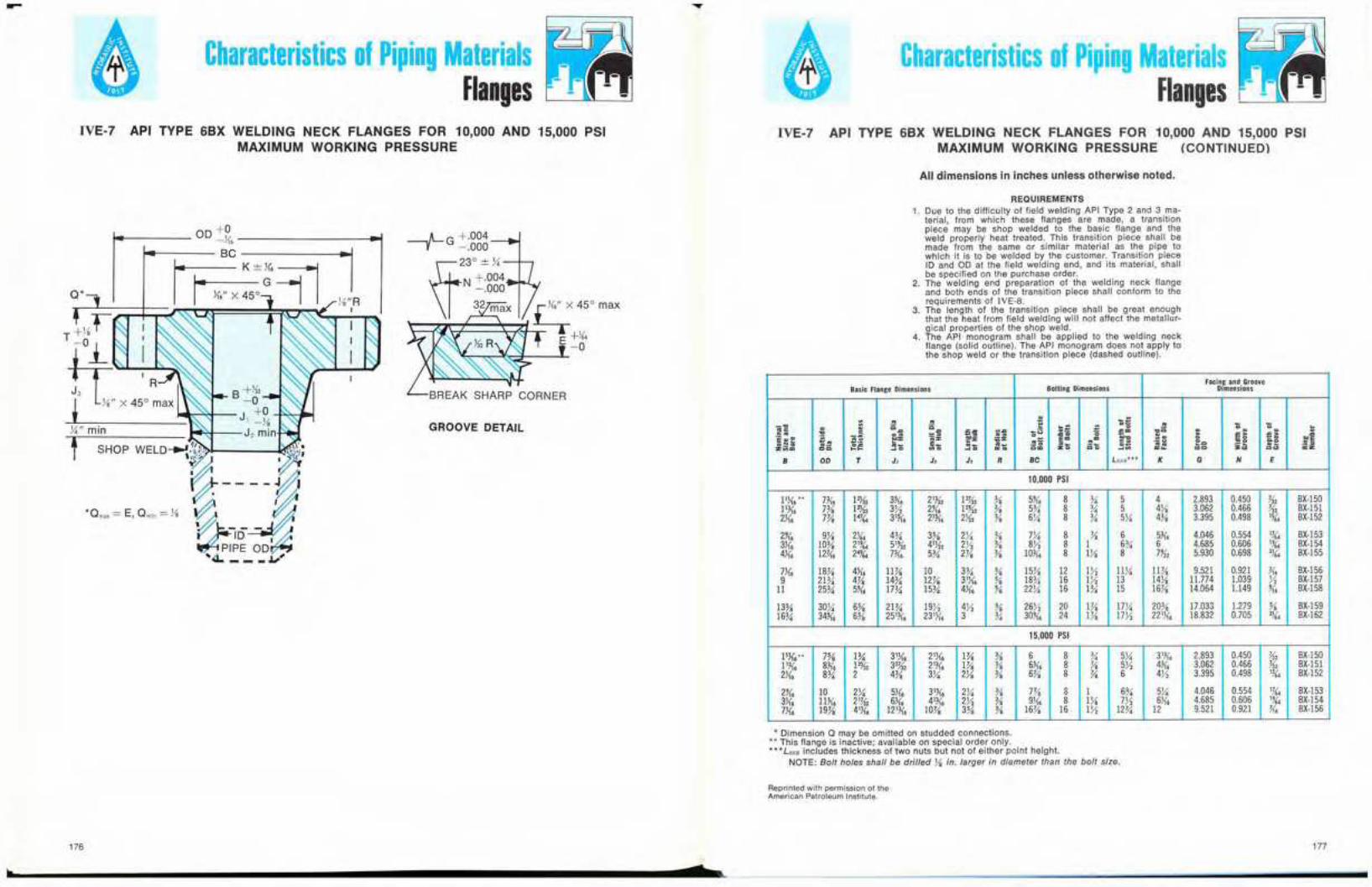
-Characteristics of Piping Materials
FlangesCharacteristics of Piping Materials
FlangesIVE-7 API TYPE 6BX WELDING NECK FLANGES FOR 10,000 AND 15,000 PSI
MAXIMUM WORKING PRESSUREIVE-7 API TYPE 6BX WELDING NECK FLANGES FOR 10,000 AND 15,000 PSI
MAXIMUM WORKING PRESSURE (CONTINUED)
All dimensions in inches unless otherwise noted.
Q'
1
BREAK SHARP CORNER
GROOVE DETAIL
REQUIREMENTS1. Due to the difficulty of field welding API Type 2 and 3 ma-
terial from which these flanges are made, a transitionpiece may be shop welded to the basic flange and theweld properly heat treated. This transition piece shall bemade from the same or similar material as the pipe towhich it is to be welded by the customer. Transition piecelD and OD at the field welding end, and its material, shallbe specified on the purchase order.
2. The welding end preparation of the welding neck flangeand both ends of the transition piece shall conform to therequirements of IYE·B.
3. The length of the transition piece shall be great enoughthat the heat from field welding will not affect the metallur-gical properties of the shop weld.
4. The API monogram shall be applied to the welding neckflange (solid outline). The API monogram does not apply tothe shop weld or the transition piece (dashed outline).
Facing and GrooveBasic Flange Dimensions Bolting Dimensions Dimensions
.セセ
Mセ -j. • ;; • >;'. セ N ァ E ...
セセ Nセ 1;u セ セ >; セ] ""Eセ '. • ... =, -, ..
BGセ. '5i; '5i; セ
ャ セ セ . ZiNセ セZu J!<'z :;:;::
N A A セ E= .= ., NZZZAセ eo セ .ZMセ NUセ
NセE_
セャゥ .- ,- Eli .- .. 3:uz セ ] " セセ セN セN =. 0= z. セセ ]セ 00 00 =z8 00 T J, J, J, • 8e Ls.·IIJ··· K G N E
10,000 PSI
I 1J{, •• 7K, 121,42 3K, RYセR QRセR % 5J{, 8 % 5 4 2.893 0.450 ii, BX-150QQセL 7% 12J.)2 3Y2 2J{, 12U2 % 5% 8 % 5 4X 3.062 0.466 ii, BX-1512J{, Wセ 14h'4 317(6 217(, 2J.)2 % 6X 8 % 5X 4% 3.395 0.498 I%'4 BX-152
2J{, 9X 21(4 4% 3% 2% % 7X 8 Y, 6 5K6 4.046 0.554 1.%"4 BX-1533J{, 10% RGセ 51U2 4'J.)2 2}1 % 8}1 8 1 Vセ 6 4.685 0.606 I%'4 BX-1544J{, 12K, RTセ 7K, Uセ 2% % 10K, 8 IX 8 7U2 5.930 0.698 2){4 BX-155
7J{, 18% 4J{6 11% 10 Sセ % 15% 12 1}1 11% 11Va 9.521 0.921 K, BX-1569 RQセ 4% QTセ 12% 31J{6 % 18% 16 1}1 13 14Ya 11.774 1.039 Y, BX-157
11 25% 5J{, 17% 15% 4J{, % 22% 16 1% 15 16% 14.064 1.149 11, BX-158
13% 30X 6% 21% 19);2 4);2 % 26J;2 20 1% 17X 20% 17.033 1.279 % BX-15916% 34K, 6% 25 1K, 23% 3 % 3011, 24 1% QWセ 22'J{6 18.832 0.705 21(4 BX-162
15,000 PSI
1lJ{6 •. 7% 1% 31J{6 21){6 1% Yo 6 8 % 5X 3W6 2.893 0.450 ii, BX-150l 1K6 8K, 1% S R セ R 21K6 1% Yo 6K, 8 Y, 5);2 4K, 3.062 0.466 K, BX-1512J{6 8% 2 4% 3X 2X Yo 6% 8 Y, 6 Tセ 3.395 0.498 1%'4 BX-152
2J{6 10 2X 5){6 31X6 2X % 7% 8 I 6% 5X 4.046 0.554 'h'4 BX-1533.l{6 11K, RQセR 6J{6 413<6 2);2 Yo 9J{6 8 IX 7Y2 6J{, 4.685 0.606 '%'4 BX-1547J{6 19% 4'J{6 121K6 10% 3% % 16% 16 1);2 12% 12 9.521 0.921 K, BX-156
* Dimension Q may be omitted on studded connections.** This flange is inactive; available on special order only.*- * LSSB includes thickness of two nuts but not of either point heIght.
NOTE: Bolt holes shall be drilled Ya in. larger in diameter than the bolt size.
Reprinted with permission of theAmerican Petroleum Institute.
176
.... ..r__.177
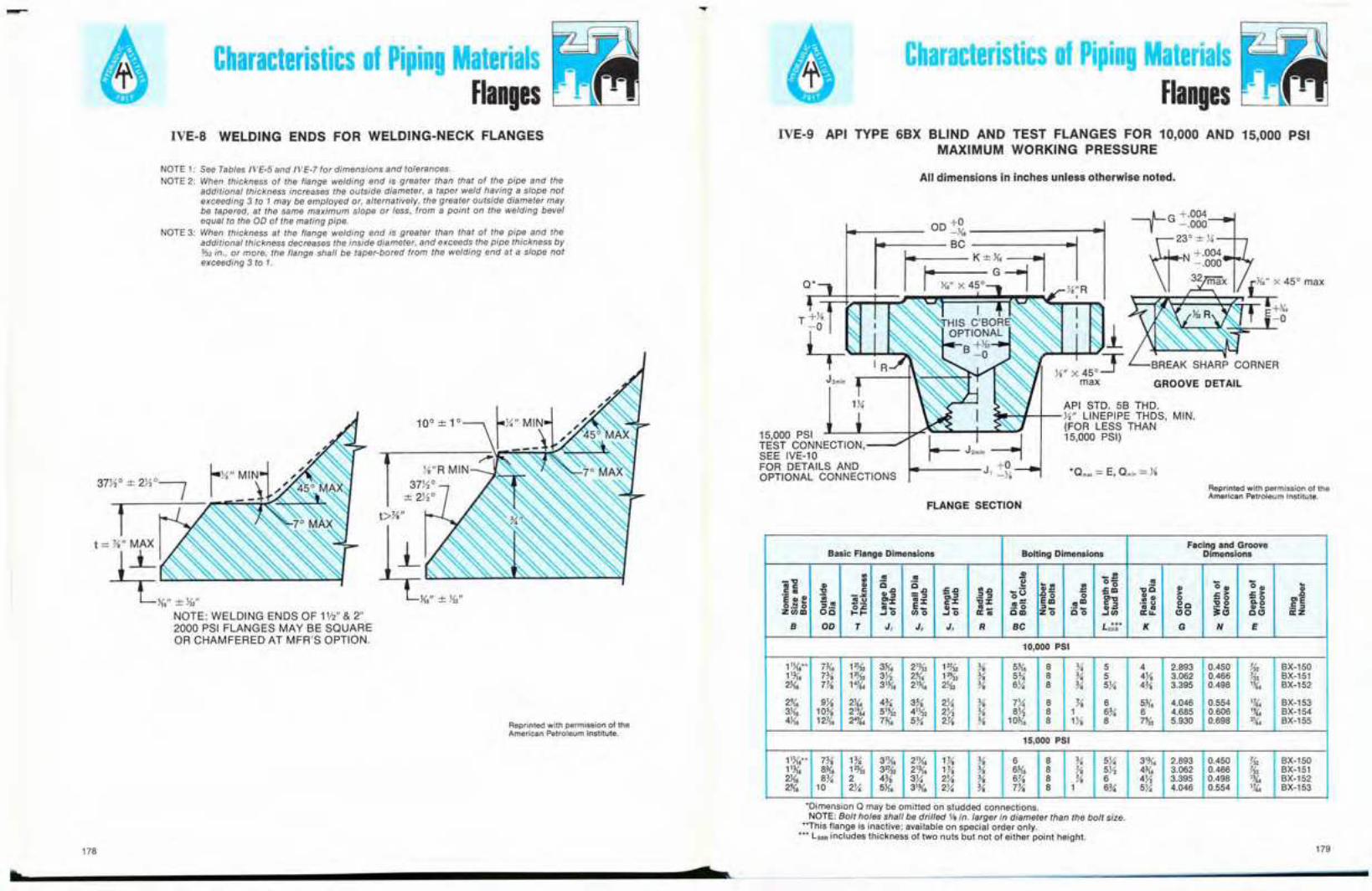
--Characteristics of Piping Materials
FlangesCharacteristics of Piping Materials
FlangesIVE-8 WELDING ENDS FOR WELDING-NECK FLANGES IVE-9 API TYPE 6BX BLIND AND TEST FLANGES FOR 10,000 AND 15,000 PSI
MAXIMUM WORKING PRESSURE
Reprinted with permission of theAmerican Petroleum Institute.
BREAK SHARP CORNER
GROOVE DETAIL
API STD. 58 THO.セセイMKMwG LlNEPIPE THDS, MIN.
(FOR LESS THAN15,000 PSI)
FLANGE SECTION
All dimensions in inches unless otherwise noted.
Facing and GrooveBasic Flange Dimensions Bolting Dimensions Dimensions
.. G .!! " ッセ-" .. 0 セ G0" 0"Ge
セ " e セ ..セ "0 "
セ
.: ca e ,,'" ='E1 "'''' .. ", -u ,,- ='" "- '" Mセ .:! :::I "'- 0セB
> ",>] セ '"eセセ ..
AAANセoャセ G:z: g':z: ,,:z: セ] E.g G'" Ol" 0 _0 OlE'5.!! セZコZ ・セ .- u ee "0 "'00._ 0 0'" G_ E_ ,,- G_ .- 0 セM ,,- GG it; L L セ .: :::Iz.,,,, Oe ...... -'0 "0 -'0 a:G e", ZO Co -'., a:LL "0 eel a:z
B 00 T J, J. J. R Be L *** K G N E'"10,000 PSI
11K,- 7)(. 1Z){z 3K. 213!z QRセR Yo 51{, 8 M 5 4 2.893 0.450 if, BX-150113<, Wセ 1Z){z 3X 21{, 121i2 Yo Uセ 8 M 5 4}$ 3.062 0.466 if, BX-1512K. Wセ 14!G 31)(, 2W, セL Yo Vセ 8 M Uセ Tセ 3.395 0.498 1)(. BX-152
2J<. 9}$ 2)(. T セ 3% 2M Yo 7M 8 Yo 6 5)(. 4.046 0.554 11(. BX-1533J{, 10% 21J{. 51'5'z 41J.s'2 2X Yo ax 8 1 Vセ 6 4.685 0.606 lJ{. BX-1544J<. 12K, 24J{. 7)(. U セ R セ Yo 10)(. 8 Qセ 8 7'5'2 5.930 0.698 ,)(. BX-155
15,000 PSI
11K... 7% Q セ 31J{, 21J{, Qセ Yo 6 8 M 5M SQセL 2.893 0.450 J<, BX-15011)(, 8)(. 1% S R セ R 21j(, Qセ Yo 6K. 8 Yo 5X 4)(. 3.062 0.466 J<, BX-15123<. Xセ 2 Tセ Sセ 2)/, Yo 6yt 8 Yo 6 4X 3.395 0.498 1)(. BX-15221{, 10 2X 5J{, SQセL Rセ Yo Wセ 8 1 6% 5X 4.046 0.554 Q セ BX-153
15,000 PSITEST CONNECTION,--'SEE IVE-10FOR DETAILS ANDOPTIONAL CONNECTIONS
Reprinted with permission of theAmerican Petroleum Institute.
10°"'1°
t>}Ia"
NOTE1: See Tables IVE·5 and /VE·7 for dimensions and tolerances.NOTE 2: When thickness of the flange welding end is greater than that of the pipe and the
additional thickness increases the outside diameter, a taper weld having a slope notexceeding 3 to 1 may be employed or, alternatively, the greater outside diameter maybe tapered, at the same maximum slope or less, from a point on the welding bevelequal to the 00 of the mating pipe.
NOTE 3: When thickness at the flange welding end is greater than that of the pipe and theadditional thickness decreases the inside diameter, and exceeds the pipe thickness by132 in., or more, the flange shall be taper-bored from the welding end at a slope notexceeding 3 to 1.
-11= Yo" MAX
セ L キ N Z N B >..-:'"x>:>"',,セセセセセNOTE: WELDING ENDS OF 1'12" & 2"2000 PSI FLANGES MAY BE SQUAREOR CHAMFERED AT MFR'S OPTION.
*Dlmension Q may be omitted on stUdded connections.NOTE: Bolt holes shall be drilled VB in. larger in diameter than the bolt size.
·*This flange is inactive; available on special order only.**" lSSB includes thickness of two nuts but not of either point height.
•178
s179

Characteristics of Piping MaterialsFlanges
Characteristics of Piping MaterialsFlanges
IVE-10 TEST AND GAGE CONNECTIONS FOR 15,OOO-LB CHRISTMAS TREES
All dimensions in inches unless otherwise noted.
IVE-11 API TYPE 6B THREADED FLANGE, COUNTERBORE DIMENSIONS
Reprinted with permission of theAmerican Petroleum Institute.
ITEM NO. DESCRIPTION
1 COLLAR
2 GLAND
3 PLUG
4 SUB ADAPTER
5 CONNECTOR, y, NPT
5
I1X THD I
L:セ G
SEAT DETAIL
li.-18NF-2LH
2Y.iz DIA. cᄋXPaeセMLiセNjZ[ZZZlMMMMLiGMMェM
TABLE 1LINE-PIPE THREADS IN API 6B FLANGES
All dimensions In inches.
Thread a. q.Size:Nominal Diameter Depth
Yo 0.47 0.125Y- 0.60 0.125Yo 0.74 0.125
Y, 0.93 0.250Y, 1.14 0.250
1 1.41 0.250
Q セ 1.75 0.250lX 1.99 0.2502 2.50 0.250
2X 3.00 0.3753 3.63 0.3753Yi 4.13 0.375
4 4.63 0.3755 5.69 0.3756 6.75 0.375
8 8.75 0.37510 10.88 0.37512 12.94 0.375
14 D 14.19 0.37516 D 16.19 0.37518 D 18.19 0.375
20 D 20.19 0.375
Reprinted with permission of theAmerican Petroleum Institute.
TABLE 2LONG CASING THREADS IN API 6B FLANGES
All dimensions in inches.
ThreadSize: a.Outside q,
Diameter Diameter Depth
4}'2 4.63 0.3755 5.13 0.3755Y2 5.63 0.375
6% 6.75 0.3757 7.13 0.3757% 7.75 0.375
8% 8.75 0.3759% 9.75 0.375
TABLE 3SHORT CASING THREADS IN
API 6B FLANGESAll dimensions in inches.
ThreadSize:
Outside a. q.Diameter Diameter Depth
4X 4.63 0.3755 5.13 0.3755X 5.63 0.375
6% 6.75 0.3757 7.13 0.3757% 7.75 0.375
8% 8.75 0.3759% 9.75 0.375
10% 10.88 0.375
117;t 11.88 0.37513% 13.56 0.37516 16.19 0.375
20 20.19 0.375
TYPE I CONNECTION
180
TYPE II CONNECTION TYPE III CONNECTION
s181
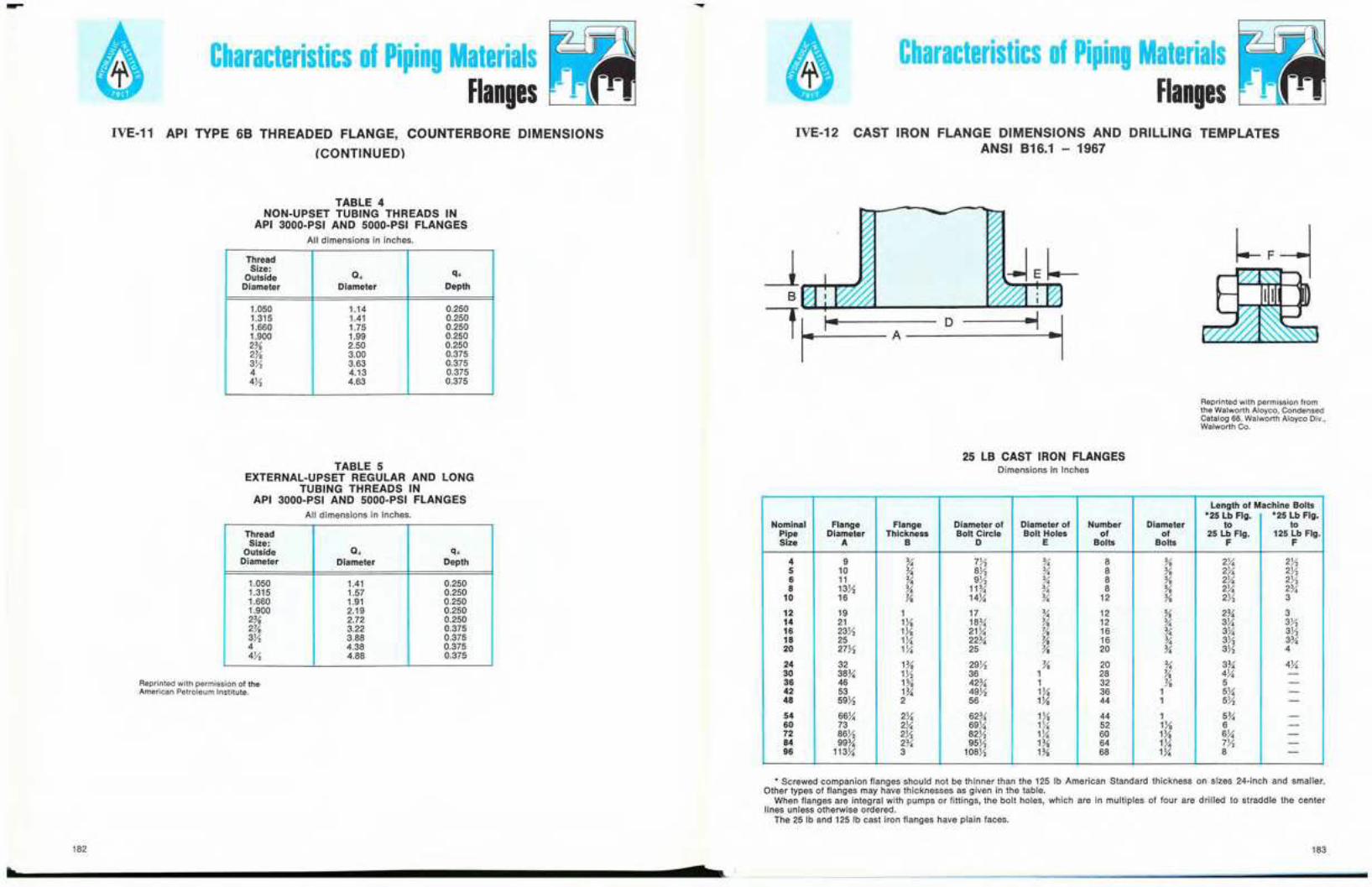
--Characteristics of Piping Materials
FlangesCharacteristics of Piping Materials
FlangesIVE·11 API TYPE 6B THREADED FLANGE, COUNTERBORE DIMENSIONS
(CONTINUED)
IVE-12 CAST IRON FLANGE DIMENSIONS AND DRILLING TEMPLATESANSI B16.1 - 1967
TABLE 4NON-UPSET TUBING THREADS IN
API 3000-PSI AND SOOO-PSI FLANGESAll dimensions in inches.
ThreadSize: a. q.Outside
Diameter Diameter Depth
1.050 1.14 0.2501.315 1.41 0.2501.660 1.75 0.2501.900 1.99 0.2502% 2.50 0.2502% 3.00 0.3753X 3.63 0.3754 4.13 0.3754}2 4.63 0.375
h
182
TABLE SEXTERNAL-UPSET REGULAR AND LONG
TUBING THREADS INAPI 3000-PSI AND SOOO-PSI FLANGES
All dimensions in Inches.
ThreadSize:
Outside a. q.Diameter Diameter Depth
1.050 1.41 0.2501.315 1.57 0.2501.660 1.91 0.2501.900 2.19 0.2502% 2.72 0.2502% 3.22 0.3753X 3.88 0.3754 4.38 0.3754X 4.88 0.375
Reprinted with permission of theAmerican Petroleum Institute.
7
Reprinted with permission fromthe Walworth Atoyco. CondensedCatalog 68, Walworth Aloyco Div.,Walworth Co.
2S LB CAST IRON FLANGESDimensions In Inches
Length of Machine Bolts'25 Lb Fig. '25 Lb Fig.
Nominal Flange Flange Diameter of Diameter of Number Diameter to toPipe Diameter Thickness Bolt Circle Bolt Holes of 01 25 Lb Fig. 125 Lb Fig.Size A B D E Bolts Bolts F F
4 9 % 7X % 8 % 2X 2Yi5 10 % 8X % 8 % 2Y4 2Yi6 11 % 9X % 8 % 214 2Yi8 l3X % 11% % 8 % 2X 2%
10 16 Yo 14J,i % 12 % 2X 3
12 19 1 17 % 12 % 2% 314 21 lYe Qbセ Va 12 % Sセ 3})16 23}) 1% RQセ Yo 16 % Sセ 3X18 25 Qセ RRセ Yo 16 % 3}) Sセ20 27}) Qセ 25 Va 20 % 331 4
24 32 1% 29}) Yo 20 % Sセ 4X30 38% 1}) 36 1 28 Yo 4X -36 46 1% 42% 1 32 Yo 5 -42 53 1% 49}) HI 36 1 5X -48 59X 2 56 1X 44 1 5}) -54 66X R セ 62% 1% 44 1 Uセ -60 73 2X 69X Q セ 52 1% 6 -72 86}) 231 82}) 1X 60 1Ya 6X -84 99% 2% 95X 1% 64 Q セ 7}) -96 113X 3 108Yi 1% 68 1X 8 -
.. Screwed companion flanges should not be thinner than the 125 Ib American Standard thickness on sizes 24-inch and smaller.Other types of flanges may have thicknesses as given in the 1able.
When flanges are integral with pumps or fittings, the bolt holes, which are in multiples of four are drilled to straddle the centerlines unless otherwise ordered.
The 25 Ib and 125 lb cast iron flanges have plain faces.
163
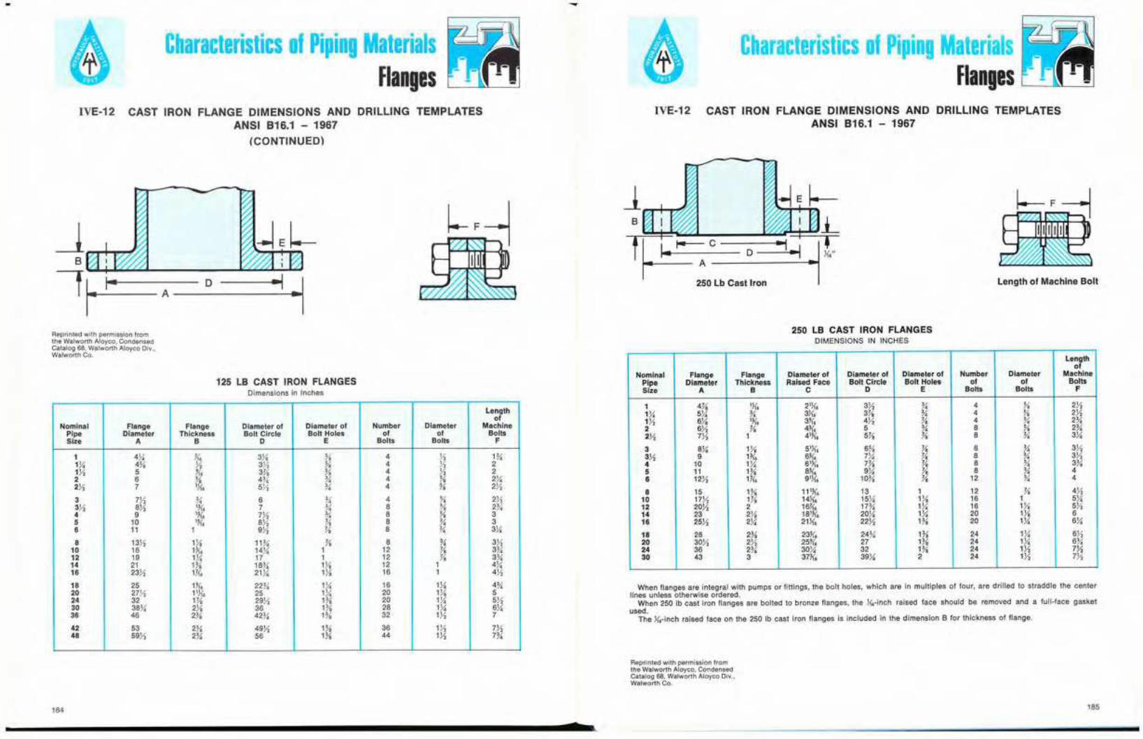
Characteristics of Piping MaterialsFlanges
Characteristics of Piping MaterialsFlanges
IVE-12 CAST IRON FLANGE DIMENSIONS AND DRILLING TEMPLATESANSI 816.1 - 1967
(CONTINUED)
IVE·12 CAST IRON FLANGE DIMENSIONS AND DRILLING TEMPLATESANSI 816.1 - 1967
Lenglh of Machine Boll
セ セ I- A C__D_-_M ⦅ B セ i ⦅ M Q ⦅
250 Lb Casllron
B
! r== A MdMMMMMセ⦅Mゥ⦅セQ
Reprinted with permission fromthe Walworth Aloyco, CondensedCatalog 68, Walworth Aloyco Div.,Walworth Co.
125 LB CAST IRON flANGESDimensions in Inches
Lengthof
Nominal Flange Flange Diameter of Diameter of Number Diameter MachinePipe Diameter Thickness Boll Circle Bolt Holes of of BoltsSize A B D E Bolts Bolts F
1 4}.S 1(. 3Ye % 4 Y, Hi1X 4% Y, Sセ % 4 Y, 21X 5 1(. 3% % 4 Y, 22 6 % 4% % 4 % 2).i2)1 7 'K6 5X % 4 % 2!43 771 % 6 % 4 % 2!;23).1 871 '11'. 7 % 8 % 2%4 9 'll. 771 % 8 % 35 10 % BX V- 8 % 36 11 1 971 V- 8 % 3X8 1371 1X 11% V- 8 % 371
10 16 W. 14X 1 12 V- 3%12 19 1).i 17 1 12 V- 3%14 21 Qセ 18% 1X 12 1 4X16 23X 1Y1' 21X 1% 16 1 41'218 25 1K6 22% 1X 16 1X 4%20 2771 11K, 25 1X 20 1X 524 32 H1i 29Yi 1% 20 1X 5X30 36% 2Ya 36 1% 28 1X 6]436 46 2% 42% 1% 32 1X 7
42 53 2% 49Yi 1% 36 1}2 77248 5971 2% 56 1% 44 1X 7%
250 LB CAST IRON FLANGESDIMENSIONS IN INCHES
Lengthof
Nominal Flange Flange Diameter of Diameter of Diameter of Number Diameter MachinePipe Diameter Thickness Raised Face Bolt Circle Boll Holes of of BollsSize A B C D E Bolts Bolts F
1 4Ve lJ{6 21){6 3X % 4 % 2X1X 5X % 3){6 3% % 4 % 27'117'1 61'8 'K. 3J16 47'1 V- 4 % 2%2 6Yi V- 411'. 5 % 8 % 2%2Yi 7Yi 1 4'U6 5!-'8 V- 8 % 3X
3 8X h セ 51){6 6% V- 8 % 37'137'1 9 1)(. 6ll. 7)4 V- 8 % 37'14 10 1Y,i 61K6 l!-'8 V- 8 % 3%5 11 1% 8ll. 9Y,i V- 8 % 46 12Yi H{6 91J{6 10% V- 12 % 4
8 15 1% 11W6 13 1 12 V- 4Yi10 17Yi 1% 14K. 15X 11'8 16 1 5X12 20Yi 2 16K6 17% 1X 16 1X 57'114 23 2X 181U6 20X 1X 20 1X 616 25X 2)4 21K6 22X 1% 20 1)4 6X
18 28 2% 23)(. 24% 1% 24 1Y,i 67'120 30X 271 25J16 27 1% 24 1X 6%24 36 2% 30X 32 1% 24 1Yi 7!130 43 3 3711'. 39X 2 24 1X 7X
When flanges are integral with pumps or fittings, the bolt holes, which are in multiples of four, are drilled to straddle the centerlines unless otherwise ordered.
When 250 Ib cast iron flanges are bolted to bronze flanges, the K6-inch raised face should be removed and a full-face gasketused.
The K6-inch raised face on the 250 Ib cast iron flanges is included in the dimension B for thickness of flange.
Reprinted with permission fromthe Walworth Aloyco. CondensedCatalog 68, Walworth Aloyco Oi ..... ,Walworth Co.
184
s185
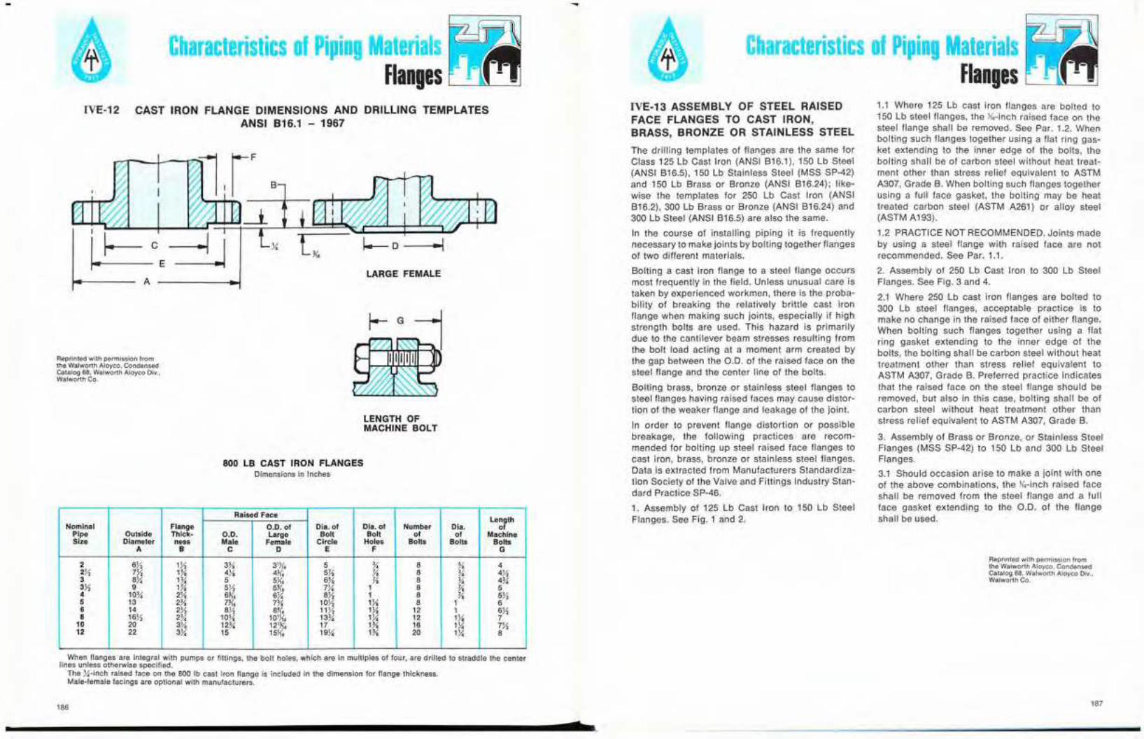
Characteristics of Piping MaterialsFlanges
Characteristics of Piping MaterialsFlanges
Raised FaceLength
Nominal Flange O.D. of Dia. of Dia. of Number Dia. ofPipe Outside t ィ ゥ 」 ォ セ O.D. Large Bolt Bolt of of MachineSize Diameter ness Male Female Circle Holes Bolts Bolts Bolts
A B C D E F G
2 6}t2 171 3% 31.J.{6 5 % 8 % 42}'2 7}2 1% 4X 4li'. 5}8 Yo 8 % 4723 Xセ 1% 5 5J.i'6 6% Yo 8 % 4%371 9 1}8 5!;2 5U6 7X 1 8 Yo 54 10% 211 6li'. ex 871 1 8 Yo 5}25 13 2% 7){. 7% lOX lYe 8 1 66 14 2}2 ex 8% 11 Y2 lX 12 1 6X8 l6X 2% 10% 101K6 13% Q セ 12 lX 7
10 20 3X 12% 121:J<6 17 1% 16 lX 7)112 22 3X 15 15J1'6 19X His 20 Hi 8
CAST IRON FLANGE DIMENSIONS AND DRILLING TEMPLATESANSI B16.1 - 1967
Reprinted with permission fromthe Walworth Aloyco, CondensedCatalog 68, Walworth Aloyco Div.,Walworth Co.
1.1 Where 125 Lb cast iron flanges are bolted to150 Lb steel flanges. the Y..-inch raised face on thesteel flange shall be removed. See Par. 1.2. Whenbolting such flanges together using a flat ring gas-ket extending to the inner edge of the bolts, thebolting shall be of carbon steel without heat treat-ment other than stress relief equivalent to ASTMA307, Grade B. When bolting such flanges togetherusing a full face gasket. the bolting may be heattreated carbon steel (ASTM A261) or alloy steel(ASTM A193).
1.2 PRACTICE NOT RECOMMENDED. Joints madeby using a steel flange with raised face are notrecommended. See Par. 1.1.
2. Assembly of 250 Lb Cast Iron to 300 Lb SteelFlanges. See Fig. 3 and 4.
2.1 Where 250 Lb cast iron flanges are bolted to300 Lb steel flanges, acceptable practice is tomake no change in the raised face of either flange.When bolting such flanges together using a flatring gasket extending to the inner edge of thebolts, the bolting shall be carbon steel without heattreatment other than stress relief equivalent toASTM A307. Grade B. Preferred practice indicatesthat the raised face on the steel flange should beremoved, but also in this case, bolting shall be ofcarbon steel without heat treatment other thanstress relief equivalent to ASTM A307, Grade B.
3. Assembly of Brass or Bronze. or Stainless SteelFlanges (MSS SP-42) to 150 Lb and 300 Lb SteelFlanges.
3.1 Should occasion arise to make a joint with oneof the above combinations, the Y..-inch raised faceshall be removed from the steel flange and a fullface gasket extending to the 0.0. of the flangeshall be used.
The drilling templates of flanges are the same forClass 125 Lb Cast Iron (ANSI B16.1), 150 Lb Steel(ANSI B16.5), 150 Lb Stainless Steel (MSS SP-42)and 150 Lb Brass or Bronze (ANSI B16.24); like-wise the templates for 250 Lb Cast Iron (ANSIB16.2), 300 Lb Brass or Bronze (ANSI B16.24) and300 Lb Steel (ANSI B16.5) are also the same.
In the course of installing piping it is frequentlynecessary to make joints by bolting together flangesof two different materials.
Bolting a cast iron flange to a steel flange occursmost frequently in the field. Unless unusual care istaken by experienced workmen, there is the proba-bility of breaking the relatively brittle cast ironflange when making such joints, especially if highstrength bolts are used. This hazard is primarilydue to the cantilever beam stresses resulting fromthe bolt load acting at a moment arm created bythe gap between the 0.0. of the raised face on thesteel flange and the center line of the bolts.
Bolting brass. bronze or stainless steel flanges tosteel flanges having raised faces may cause distor-tion of the weaker flange and leakage of the joint.
In order to prevent flange distortion or possiblebreakage, the following practices are recom-mended for bolting up steel raised face flanges tocast iron, brass, bronze or stainless steel flanges.Data is extracted from Manufacturers Standardiza-tion Society of the Valve and Fittings Industry Stan-dard Practice SP-46.
1. Assembly of 125 Lb Cast Iron to 150 Lb SteelFlanges. See Fig. 1 and 2.
IVE-13 ASSEMBLY OF STEEL RAISEDFACE FLANGES TO CAST IRON,BRASS, BRONZE OR STAINLESS STEEL
I-G
LARGE FEMALE
LENGTH OFMACHINE BOLT
1--0
IVE-12
Reprinted with permission fromthe Walworth Atoyco, CondensedCatalog 68, Walworth Aloyco Oiv.,Walworth Co.
800 LB CAST IRON FLANGESDimensions in Inches
ャ セ M \-=iJA
When flanges are integral with pumps or fittings, the bolt holes, which are in multiples of four, are drilled to straddle the centerlines unless otherwise specified.
The セ M ゥ ョ 」 ィ raised face on the 800 Ib cast iron flange is included in the dimension for flange thickness.Male-female facings are optional with manufacturers.
186
s187

SectionY
C-I---__...
Acceptable Practice
ASSEMBLY OF 250 LB. CAST IRON FLANGES TO300 LB. STEEL FLANGES
D
cエ]]]セ⦅MMャ
D--£j
Characteristics of Piping MaterialsFlanges
ASSEMBLY OF 125 LB. CAST IRONFLANGES TO 150 LB. STEEL FLANGES
IVE-13 ASSEMBLY OF STEEL RAISED FACE FLANGES TO CAST IRON,
BRASS, BRONZE OR STAINLESS STEEL (CONTINUED)
B ---""11--1
D---£:1
BOLTING PRACTICE FOR FLANGES OF DISSIMilAR METAL
Reprinted with permission fromthe Walworth Aloyco, CondensedCatalog 68, Walworth Aloyco Div..Walworth Co.
Flange Combination Facing Gasket Bolting Used
125 Lb C.1. K6-in. raised face on the steel Flat Ring Carbon Steel without heat treatment other than stressto flange shall be removed. Type relief, equivalent to ASTM A307, Grade B.
150 Lb Steel
See Fig. 1 & 2 Full Face May be heat treated carbon steel, equivalent to ASTMType A261 or Alloy Steel equivalent to A193.
250 Lb C.1. No change necessary in raised Flat Ring Carbon Steel, without heat treatment other than stressto face of either flange. However, Type relief, equivalent to ASTM A307, Grade B.
300 Lb Steel preferred practice indicates thatraised face on steel flange
See Fig. 3 & 4 should be moved.
Brass, Bronze, or K6-ln. raised face on the steel Full Face Carbon Steel, without heat treatment other than stressStainless Steel flange shall be removed. Type Only. relief, equivalent to ASTM A307, Grade 8, or heat
(MSS SP-42) to Steel treated carbon steel, equivalent to ASTM A261 orAlloy Steel equivalent to A193.
A 250 LB. CAST IRON A250 LB. CAST IRONFLANGE WITH j.{1 IN FLANGE WITH )f, IN.RAISED FACE RA)5eD FACE
BFL.AT RING GASKET BFLAT RING GASKETEXTENDING TO THE INNER EXTENDING TO THE INNEREDGE OF THE BOLTS EDGE OF THE BOLTS
C300 LB, STEEL FLANGE WITH C300 LB. STEEL FLANGE WITH){6 IN. RAISED FACE NOT REMOVED .1{, IN. RAISED FACE REMOVED
DCARBON STEEL BOLTING ONLY DCAABON STEEL BOLTING ONLYASTM A307 GRADE 8 OR EQUIVALENT ASTM A307 GRADE 8 OR
EQUIVALENT
Useful Information
,
" iii/
.,
I:1
ill
I,.
. -:'- I. ..-- II.._--.-
IIIy-, .
/:'\
"'" =--
FIG. 4FIG. 3
A 125 LB.CAST IRON FLANGE
B FULL FACE GASKETEXTENDING TO 00OF FLANGE
C 150 LB. STEEL FLANGE WITHK, IN. RAISED FACE REMOVED
OCARBON OR ALLOY STEELBOL.TING MAY BE USED
FIG. 2FIG. 1
A 125 LB.CAST IRON FLANGE
B FLAT RING GASKETEXTENDING TO THE INNEREDGE OF THE BOL15
elSO LB. STEEL FLANGE WITHK, IN. RAISED FACE REMOVED
OCARBON STEEL BOL.TING ONLYASTM A307 GRADE B OR EQUIVALENT
188
s
-Useful InformationConversion Tables
•
VA·1 CONVERSION TABLE-TEMPERATURE
Degrees Celsius = (Degrees Fahrenheit -32) x 5
9
Degrees Fahrenheit = (Degrees Celsius x 9)+ 325
Degrees Kelvin (K) = Degrees Ceisius + 273.15
Degrees Rankine (R) = Degrees Fahrenheit + 459.69
(0 degrees K or R = absolute zero)
Common equivalents: O°C = 32°F20°C = 68°F25°C = 77°F
100°C = 212°F
VA-2 ACCELERATION OF GRAVITY (AT SEA LEVEL) (g)
Latitude,deg. 0 10 20 30 40 45 50 60 70 80 90
g, ftlsec2 32.088 32.093 32.108 32.130 32.158 32.174 32.187 32.215 32.238 32.253 32.258
g, m/s 2 9.780 9.782 9.786 9.793 9.802 9.807 9.811 9.819 9.826 9.831 9.832
Note: Correction for altitude above sea level:
-0.003m/s 2 per 1000 m
-0.003 ft/sec 2 per 1000 ft
191

...Characteristics of Piping Materials
Conversion TablesVA·3 CONVERSION TABLE-PHYSICAL DIMENSIONS
TABLE A-PHYSICAL DIMENSIONS-LENGTH
Useful InformationConversion Tables
VA-3 CONVERSION TABLE-PHYSICAL DIMENSIONS
TABLE C-PHYSICAL DIMENSIONS-VOLUME
•
U.S. CUSTOMARY UNITS SI UNITS OTHER METRiC UNITS
inch foot yard rod mile naul. meter centimeter kilometer(in.) (ft) (yd) (mi) mile (m) (em) (km)
1 0.0833 0.02778 - - - 0.0254 2.54 -
12 1 0.3333 - - - 0.3048 30.48 -
36 3 1 0.1818 .000568 .000494 0.9144 91.44 -
198 16.5 5.500 1 .003125 .002716 5.0292 502.9 .00503
63360 5280 1760 320 1 0.8690 1609 160935 1.609
72913 6076.1 2025.4 368.25 1.1508 1 1852 185200 1.852
39.37 3.281 1.0936 - - - 1 100 0.001
0.3937 0.03281 0.01094 - - - 0.01 1 0.00001
39370 3281 1093.6 198.84 0.6214 .5400 1000 100000 1
TABLE B-PHYSICAL DIMENSIONS-AREA
U.S. CUSTOMARY UNITS 5.1. UNIT OTHER METRIC UNITS
squaresquare square hectometer square
square inch square foot square yard squaremile circular mil square meter millimeter centimeter (hectue) kilometer(in.1) (ttl) セ L セ acre H i ャ セ ャ (eir mil) Hュセ (mm1) (em!) H ィ ュ セ (kmt)
I 0.00694 O.OOO7711 0.1594 X 10⁻⁶ 2.4910 X la-It 1.2732x 10' 6.4517 X 10-- 645.17 6.4517 6.4517 X to- 6.4517 X 10⁻¹¹
144 I 0.11111 2.296 X 10-' 3.5871 X 10-' - 0.0929 92900 92' 0.0929 X 10- 0.0929 X 10--
1296 , 1 0.000207 0.3228 X 10-' - 0.8361 0.8361 X 10' 0.8361 X 10' 0.8361 X 10- 0.8361 X 10--
- 43560 4840 1 0.001563 - 4.047 X 10³ - 0.4047 4.047 X 10⁻³
40.1449X 10' 27.878 X 10' 3.0976 X 10' 640 1 - 2.5889 X 10' - - 258.89 2.5889
0.7854 X 10-' 5.1112 X 10 " I 0.5067 X 10⁻¹ 0.5067 X 10⁻¹ 0.5067 X 10-'
1550 10.76 1.196 - - - 1 1 X QPセ 1 X 10< 1 X 10-< -
0.001550 - - - - 1973.6 1 X 10-' 1 1 X 10⁻¹ - -0.1550 0.001076 197360 1 X 10-< 100 1
107600 11960 2.471 0.3861 X 10⁻¹ - 10000 1 0.010
- 10.76x 10' 1.196 X la' 247.1 0.38614 - 1 X la' - - 1 X 101 1
192
s
U.S. CUSTOMARY UNITS S.1. UNIT OTHER METRIC UNIT
cubic inch US gallon Imp. gallon cubic foot barrel- cubic meter liter(in.)) (US gal) (Imp gal) (ft') (bbl) (m') (I)
1 0.00433 0.00360 0.000579 0.000103 0.00001639 0.01639
231 1 0.8327 0.1337 0.0238 0.003785 3.785
277.42 1.2009 1 0.1606 0.0286 0.004546 4.546
1728 7.481 6.229 1 0.1780 0.02832 28.32
9702 42 34.97 5.615 1 0.15897 158.97
61024 264.17 220 35.31 6.2898 1 1000
61.024 0.2642 0.2198 0.0353 0.00630 0.001 1
* By trade custom, one barrel petroleum 011 is equal to 42 US gal.
VA·4 CONVERSION TABLE-VELOCITY
U.S. CUSTOMARY UNITS S.I. UNIT OTHER METRIC UNITS
meters per centimeters meters kilometersfeet per min feet per sec miles per hr sec per sec per min per hr
('pm) (Ips) (mph) (m/s) (em/sec) (m/min) (km/hr)
1 0.01667 0.01136 0.00508 0.5080 0.3048 0.01829
60 1 0.6818 0.3048 30.48 18.29 1.097
88 1.467 1 0.447 44.70 26.82 1.609
196.85 3.281 2.237 1 100 60.0 3.60
1.9685 0.03281 0.02237 0.010 1 0.6 0.036
3.281 0.05468 0.03728 0.01667 1.667 1 0.06
54.68 0.9113 0.6214 0.2778 27.78 16.67 1
NOTE: 1 knot = 1.15155mph or 1.8532km/hr.
Angular Velocity1 revolution per minute (rpm) = 0.1047 radians per second1 radian per second = 9.55 revolutions per minute
193

..Useful InformationConversion Tables
Useful InformationConversion Tables
VA·5 CONVERSION TABLE-CAPACITY VA·6 CONVERSION TABLE-MASS, WEIGHT AND FORCE (CONTINUED)
Or, the weight of a body having a mass of 1 kilo-gram will be, at sea level,
1 x 32.088---- = 0.9974 Ib force
32.174
Definitions:
2. Weight is a force and is dependent on the ac-celeration of gravity, and therefore varies withlatitude and altitude. The pound (Ib) and kilo-gram (kg) have been commonly used units, butproperly should be termed pound force andkilogram force. The weight of a body having amass of 1 pound will be 1 pound at sea ieveland 45° latitude, but wili be different at otherlocations where the acceieration of gravity isdifferent than 32.174 ft/sec'. For instance, at theequator (0° latitude) and sea level, where theacceleration of gravity is 32.008, the weight of abody having a mass of 1 pound will be
= 1 x 10' dynes
Note: Use of the unit "kilogram force" should beavoided.
1.02 x 10-' kg forcekg force
9.807
11 newton (N) =
The slug is the mass which, if acted on by aforce of 1 pound, wili accelerate at a rate of1 ft/sec'; 1 slug = 32.1741b
The dyne is the force which, applied to a massof 1 gram (g) gives it an acceleration of 1 cm/
1sec'; 1 dyne =-- gram force
980.7 = 1.02 x 10-- kg force
The newton is the force which, if applied to amass of 1 kilogram (kg) gives it an accelerationof 1 m/s;
3. The poundal is the force which, appiied to amass of 1 pound, gives it an acceleration of
11 ft/sec'; 1 poundal = --Ib
32.174
= 0.997 kg force1 x 9.780
9.807
.. By trade custom, one barrel petroleum oil is equal to 42 US gal.
0.1247gpm =--w- X Ib/hr when w =denslly, Ib/eu ft
U.S. CUSTOMARY UNITS S.I. UNIT OTHER METRIC UNITS
Millionsof US cubic cubic
gallons US gallons Imp. gallons cubic feet *barrels meters liters metersper day per min per min per sec per hr per sec per min per hr(MGD) (gpm) (Igpm) (cfs) (bph) (m'/s) (llmin) (m'/hr)
1 694.4 578 1.547 992 0.0438 2628 157.72
0.00144 1 0.8327 0.002228 1.4286 63.06 x 10-' 3.785 0.2271
0.00173 1.2009 1 0.00268 1.7156 75.77 x 10⁻⁶ 4.5454 0.2728
0.64636 448.86 373.8 1 641.23 2.832 X 10-' 1699 101.952
0.00100 0.7000 0.5829 0.00156 1 44.166X 10-' 2.6495 0.1590
22.824 15852 13188 35.316 22643 1 60000 3600
0.000380 0.2642 0.2198 0.000586 0.3774 16.67 x 10⁻⁶ 1 0.0600
0.00634 4.4028 3.666 0.00981 6.2898 2.777 x 10⁻⁴ 16.667 1
VA-6 CONVERSION TABLE-MASS, WEIGHT AND FORCE
Definitions:1. Mass is absolute, the pound (Ib) and kilogram (kg) are most commonly used units, the kilogram is the
81 unit.
U.S. CUSTOMARY UNITS (avoirdupois) S.I. UNIT OTHER METRIC UNITS
grain ounce pound short long kilogram gram metric(gr) (oz) (Ib) Ion Ion (kg) (g) Ion
1 0.002286 - - - - 0.0648 -
437.5 1 0.0625 - - 0.02835 28.35 -
7000 16 1 - - 0.4536 453.6 -
- - 2000 1 .8929 907.2 - 0.9072
- - 2240 1.12 1 1016 - 1.016
15432 35.27 2.205 - - 1 1000 0.001
15.432 0.03527 0.002205 - - 0.001 1 -
- - 2205 1.102 0.9842 1000 1 000000 1
VA-7 CONVERSION TABLE-DENSITY
U.S. CUSTOMARY UNITS S.1. UNIT OTHER METRIC UNIT
kilogramspounds per pounds per pounds per per cubic
grams per milliliterUS gallon cubic fool cubic inch meier(Ib/US gal) (Ib/ft') (Ib/in.') (k9/m') (g/ml)
1 7.481 0.004329 119.8 0.1198
0.1337 1 0.0005787 16.02 0.01602
231 1728 1 27680 27.68
0.008345 0.06243 3.613 x 10⁻⁵ 1 0.001
8.345 62.43 0.03613 1000 1
Note: Density expressed in grams per milliliter = specific gravity = grams per cubic centimeter.
194 195
b 2

..Useful InformationConversion Tables IJ·_·····..........セ..セセ ........
セセゥZセェ JMセᆬ ••
Useful InformationVolume of Round and Rectangular Tanks
VA-8 CONVERSION TABLE-PRESSURE VB CONVERSION TABLES-VOLUME OF ROUND AND RECTANGULAR TANKS
VA-9 CONVERSION TABLE-ENERGY, WORK, HEAT
Units and symbols: pounds per square inch (psi)pascal (Pa) = 1 N/m' (81 unit)kilograms per square centimeter (kg/em')bar
1 psi = 0.0703 kg/em' = 6894.76 N/m' = 6.894 kPa1 kg/em' = 14.22 psi = 9. 80665 x 10' N/m' = 98.0665 kPa1 atmosphere = 14.7 psi = 1.0332 kg/m' = 10.13 x 10' N/m' = 101.3 kPa1 metric atmosphere = 98.0665 kPa1 pascal = 1.45 x 10-' psi = 1.02 x 10-' kg/em'1 bar = 10' Pa = 100 kPa
u.s. CUSTOMARY UNITS S.I. UNIT OTHER METRIC UNITS
foot pounds British thermal units horsepower·hrs joules calories kilowatt-hrs(fHb) (Blu) (hp·hr) (J) (cal) (kWh)
1 0.001285 - 1.356 0.3238 -
778.2 1 .0003930 1055 252.0 0.0002931
- 2544 1 - 641 200 0.7457
0.7376 0.0009478 - 1 0.2388 -
3.088 0.003968 - 4.187 1 -
- 3412 1.341 - 859900 1
NUMBER OF U.S. GALLONS IN ROUND TANKS FOR ONE FOOT IN DEPTH
Reprinted with permission from theAllis-Chalmers Corporation.
To find the capacity of tanks greater than the largest given in the table, look in the table for a Tank of one-half the given size andmultiply its capacity by 4, or one of one-third its size and multiply its capacity by 9, etc.
NUMBER OF U.S. GALLONS IN RECTANGULAR TANKS FOR ONE FOOT IN DEPTH
Width length of Tank.f
Tank 3' 3'-6" 4' 4'-6" S' 5'-S" S' S'-6" " 7'-S" " 8'·S" .' 9'-S" 10' 10'-6" 11' 11'-6" 12'
2· 44.88 52.36 59.84 67.32 74.81 82.29 89.77 97.25 104.73 112.21 119.69 127.17 134.65 142.13 149.61 157.09 164.57 172.05 179.532'·6" 56.10 65.45 74.80 84.16 93.51 102.86 ll2.21 121.56 130.91 140.26 149.61 158.96 168.31 177.66 187.01 196.36 205.71 215.06 224.413' 67.32 78.54 89.77 100.99 112.21 123.43 134.65 145.87 157.09 168.31 179.53 190.75 201.97 213.19 224.41 235.63 246.86 258.07 269.303'-6" - 91.64 104.73 117.82 130.91 144.00 157.09 170.18 183.27 196.36 209.45 222.54 235.63 248.73261.82 274.90 288.00 301.09 314.184' - - ll9.69 134.65 149.61 164.57 179.53 194.49 209.45 224.41 239.37254.34 269.30 284.26 299.22 314.18 329.14 344.10 359.064'-6" - - - 151.48 168.31 185.14 201.97 218.80 235.63 252.47 269.30 286.13 302.96 319.79 336.62 353.45 370.28 387.11 403.945· - - - - 187.01 205.71 224.41 243.11 261.82 280.52 299.22 317.92 336.62 355.32374.03 392.72 411.43 430,13 448.835'·6" - - - - - 226.28 246.86 267.43 288.00 308.57 329.14 349.71 370.28 390.85 411.43 432.00 452.57 473.14 493.716' - - - - - - 269.30 291.74 314.18 336.62 359.06 381.50403.94 426.39 448.83 411.27493.71 516.15 538.596'-6" - - - - - - - 316.05 340.36 364.67 388.98 413.30 437.60 461.92 486.23510.54 534.85 559.16 583.47
" - - - - - - - - 366.54 392.72 418.91 445.09 471.27 497.45 523.64 549.81 575.99 602.18 628.361'-6" - - - - - - - - - 420.78 448.83 476.88 504.93 532.98 561.04 589.08617.14 645.19 673.24
" - - - - - - - - - - 478.75 508.67 538.59 568.51 598.44 628.36 658.29 688.20 718.128'·6" - - - - - - - - - - - 540.46 572.25 604.05 635.84 667.63699.42 731.21 763.009' - - - - - - - - - - - - 605.92 639.58 673.25 706.90 740.56 774.23 807.899'-6" - - - - - - - - - - - - - 675.ll 710.65 746.17 781.71 811.24 852.77
'0' - - - - - - - - - - - - - - 748.05 785.45 822.86 860.26 897.6610'-6" - - - - - - - - - - - - - - - 824.73 864.00 903.26 942.5611' - - - - - - - - - - - - - - - - 905.14 946.29 987.4311'-6" - - - - - - - - - - - - - - - - - 989.29 1032.312· - - 1077.2
Cubic Cubic Cubic Cubic Cubic ColeDJa. N•. ft. and Dia. N•• ft. and Dia. N•. ft. and Dia. N•. tt. and Dia. N•. ft. and Dla. N•• ft. and•1 U. S. Area in ., U. S. Area in .1 U. S. Area in ., U. S. Area in ., U. S. Area in ., U. S. Area In
Tanks gals. sq. ft. Tanks gals. sq. ft. Tanks gals. sq. ft. Tanks gals. sq. ft. Tanks gals. sq. ft. Tanks gals. sq. ft.
" 5.87 .785 3'· 4" 65.28 8.727 5'· 8" 188.66 25.22 12· 846.03 113.10 ,,' 2120.90 283.53 26' 3971.60 530.931'· 1" 6.89 .922 3'· 5" 68.58 9.168 5'· 9" 194.25 25.97 12'·3" 881.65 117.86 19'-3" 2177.10 291.04 26'·3" 4048.40 541.191'· 2" ,. 1.069 3'- 6" 71.97 9.621 5'-10" 199.92 26.73 12'-6" 918. 122.72 19'-6" 2234. 298.65 26'-6" 4125.90 551.551'- 3" 9.18 1.227 3'· 7" 75.44 10.085 5'-11" 205.67 27.49 12'·9" 955.09 127.68 19'-9" 2291.70 306.35 26'-9" 4204.10 562.1'· 4" 10.44 1.396 3'- 8" 78.99 10.559 6· 211.51 28.27 13' 992.91 132.73 20· 2350.10 314.16 27· 4283. 572.561'- 5" 11.79 1.576 3'- 9" 82.62 11.045 6' -3" 229.50 30.68 13'-3" 1031.50 137.89 20'-3" 2409.20 322.06 27'·3" 4362.70 583.211'- 6" 13.22 1.767 3'·10" 86.33 11.541 6'- 6" 248.23 33.18 13'-6" 1070.80 143.14 20'·6" 2469.10 330.06 27'·6" 4443.10 593.961'· 7" 14.73 1.969 3'·11" 90.13 12.048 6'- 9" 267.69 35.78 13'·9" 1110.80 148.49 20'-9" 2529.60 338.16 27'·9" 4524.30 604.811'- 8" 16.32 2.182 4' 94. 12.566 7' 287.88 38.48 14· 1151.50 153.94 21' 2591. 346.36 28· 4606.20 615.751'· 9" 17.99 2.405 4'· 1" 97.96 13.095 1'- 3" 308.81 41.28 14'-3" 1193. 159.48 21'-3" 2653. 354.66 28'-3" 4688.80 626.801'·10" 19.75 2.640 4'- 2" 102. 13.635 7'· 6" 330.48 44.18 14'-6" 1235.30 165.13 21'·6" 2715.80 363.05 28'-6" 4772.10 637.941'-11" 21.58 2.885 4'- 3" 106.12 14.186 1'- 9" 352.88 47.17 14'·9" 1278.20 170.87 21'-9" 2779.30 371.54 28'·9" 4856.20 649.182' 23.50 3.142 4'· 4" 110.32 14.748 " 376.Ql 50.27 15' 1321.90 176.71 22· 2843.60 380.13 29· 4941. 660.522'· 1" 25.50 3.409 4'- 5" 114.61 15.321 8'· 3" 399.88 53.46 15'-3" 1366.40 182.65 22'·3" 2908.60 388.82 29'·3" 5026.60 671.962'- 2" 27.58 3.687 4'- 6" 118.97 15.90 8'- 6" 424.48 56.75 15'·6" 1411.50 188.69 22'·6" 2974.30 397.61 29'·6" 5112.90 683.492'· 3" 29.74 3.976 4'· 7" 123.42 16.50 8'· 9" 449.82 60.13 15'-9" 1457.40 194.83 22'-9" 3040.80 406.49 29'-9" 5199.90 695.132'- 4" 31.99 4.276 4'· 8" 127.95 17.10 9' 475.89 63.62 ". 1504.10 201.06 23' 3108. 415.48 30' 5287.70 706.862'- 5" 34.31 4.587 4'· 9" 132.56 17.72 9'· 3" 502.70 67.20 16'-3" 1551.40 207.39 23'·3" 3175.90 424.56 30'·3" 5376.20 718.692'- 6" 36.72 4.909 4'-10" 137.25 18.35 9'· 6" 530.24 70.88 16'-6" 1599.50 213.82 23'·6" 3244.60 433.74 30'·6" 5465.40 730.622'- 7" 39.21 5.241 4'·ll " 142.02 18.99 9'- 9" 558.51 74.66 16'-9" 1648.40 220.35 23'·9" 3314. 443.01 30'·9" 5555.40 742.642'- 8" 41.78 5.585 5· 146.88 19.63 '0· 587.52 78.54 17' 1697.90 226.98 24· 3384.10 452.39 31' 5646.10 754.772'· 9" 44.43 5.940 5'- 1" 151.82 20.29 10'· 3" 617.26 82.52 11'-3" 1748.20 233.71 24'-3" 3455. 461.86 31'·3" 5737.50 766.992'-10" 47.16 6.305 5'· 2" 156.83 20.97 10'· 6" 642,74 86.59 17'-6" 1799.30 240.53 24'·6" 3526.60 471.44 31'·6" 5829.70 779.312'·ll " 49.98 6.681 5'· 3" 161.93 21.65 10'· 9" 678.95 90.76 11'-9" 1851.10 247.45 24'·9" 3598.90 481.11 31'-9" 5922.60 791.733' 52.88 7.069 5'- 4" 167.12 22.34 !l' 710.90 95.03 18· 1903.60 254.47 25· 3672. 490.87 32' 6016.20 804.253'- 1" 55.86 7.467 5'· 5" 172.38 23.04 11'- 3" 743.58 99.40 18'·3" 1956.80 261.59 25'·3" 3745.80 500.74 32'·3" 6110.60 816.863'- 2" 58.92 7.876 5'· 6" 177.72 23.76 II '. 6" 776.99 103.87 18'-6" 20In.8f} 268.80 25'-6" 3820.30 510.71 32'·6" 6205.70 829.583'- 3" 62.06 8.296 5'· 7" 183.15 24.48 11'. 9" 811.14 108.43 18'·9" 2065.50 276.12 25'-9" 3895.60 520.77 32'·9" 6301.50 842.39
CONVERSION TABLE-POWERVA-10
U.S. CUSTOMARY UNITS S.1. UNIT OTHER METRIC UNITS
foot-pounds British thermalpersec. horsepower units per sec watts kilowatts metric
(It-Ib/sec) (hp) (Btu/sec) (W) (kW) horsepower
1 0.00182 0.001285 1.356 0.001356 0.00184
550 1 0.7068 7.457 x 10² 0.7457 1.014
778.2 1.415 1 1.055 X 10' 1.055 1.434
0.7376 1.341 x 10⁻³ 9.478 X QPMセ 1 0.001 0.00136
737.6 1.341 0.9478 1000 1 1.360
542.5 0.9863 0.6971 7.355 X 10' 0.7355 1
196 197
b 7

,.
Useful InformationBarometric Pressure-Effect of Altitude
Useful InformationCircumference and Areas of Circles
:l1)-_.,
ZZZZZZセ
セセヲゥZセセ---'.
セ
VC BAROMETRIC PRESSURE-EFFECT OF ALTITUDE VD·1 CIRCUMFERENCES AND AREAS OF CIRCLES
Diameter Circum. Area Diameter Circum. Area Diamete Circum. Area Diamete Circum. Area
Ve .3927 .0123 ax 25.525 51.849 16Ve 50.653 204.22 24X 75.791 457.11Y. .7854 .0491 Xセ 25.918 53.456 QVセ 51.051 207.39 24X 76.184 461.86% 1.1781 .1104 8% 26.311 55.088 16% 51.444 210.60 24% 76.576 466.64Y, 1.5708 .1963 Xセ 26.704 56.745 16Y, 51.836 213.82 24}} 76.969 471.44Y, 1.9635 .3068 8% 27.096 58.426 16% 52.229 217.08 24Y, 77.362 476.26% 2.3562 .4417 8% 27.489 60.132 QVセ 52.622 220.35 24% 77.754 481.11Y, 2.7489 .6013 Xセ 27.882 61.862 16Ye 53.014 223.65 24Y, 78.147 485.98
1 3.1416 .7854 9 28.274 63.617 17 53.407 226.98 25 78.540 490.87lX 3.5343 .9940 9X 28.667 65.397 l1X 53.800 230.33 25X 78.933 495.79lX 3.9270 1.2272 9X 29.060 67.201 17M 54.192 233.71 25X 79.325 500.74'% 4.3197 1.4849 9% 29.452 69.029 17% 54.585 237.10 25% 79.718 505.711}1 4.7124 1.7671 9X 29.845 70.882 171'2 54.978 240.53 251'2 80.111 510.71Qセ 5.1051 2.0739 9% 30.238 72.760 17Y, 55.371 243.98 25Y, 80.503 515.721% 5.4978 2.4053 9% 30.631 74.662 17% 55.763 247.45 25% 80.896 520.77Qセ 5.8905 2.7612 Yセ 31.023 76.589 17}l 56.156 250.95 25}'. 81.289 525.842 6.2832 3.1416 10 31.416 78.540 18 56.549 254.47 26 81.681 530.93lX 6.6759 3.5466 lOX 31.809 80.516 l8X 56.941 258.02 261'8 82.074 536.052X 7.0686 3.9761 lOX 32.201 82.516 l8X 57.334 261.59 26M 82.467 541.192'" 7.4613 4.4301 10% 32.594 84.541 18% 57.727 265.18 26% 82.860 546.3521'2 7.8540 4.9087 101'2 32.987 86.590 18Y, 58.119 268.80 26X 83.252 551.552% 8.2467 5.4119 lOX 33.379 88.664 18% 58.512 272.45 26Y, 83.645 556.762% 8.6394 5.9396 10% 33.772 90.763 18% 58.905 276.12 26% 84.038 562.002% 9.0321 6.4918 10% 34.165 92.886 18Y, 59.298 279.81 26Y, 84.430 567.273 9.4248 7.0686 11 34.558 95.033 19 59.690 283.53 27 84.823 572.563X 9.8175 7.6699 l1X 34.950 97.205 19X 60.083 287.27 27X 85.216 577.873M 10.210 8.2958 l1X 35.343 99.402 19X 60.476 291.04 27X 85.608 583.213% 10.603 8.9462 11% 35.736 101.62 19% 60.868 294.83 27% 86.001 588.5731'2 10.996 9.6211 l1X 36.128 103.87 19X 61.261 298.65 211'2 86.394 593.963% 11.388 10.321 11% 36.521 106.14 19% 61.654 302.49 27% 86.786 599.373M 11.781 11.045 11% 36.914 108.43 19% 62.046 306.35 27% 87.179 604.813% 12.174 11.793 11% 37.304 110.75 19Y8 62.439 310.24 27% 87.572 610.274 12.566 12.566 12 37.699 113.10 20 62.832 314.16 28 87.965 615.754X 12.959 13.364 12X 38.092 115.47 20X 63.225 318.10 28X 88.357 621.264X 13.352 14.186 12X 38.485 117.86 20X 63.617 322.06 2ax 88.750 626.804% 13.744 15.033 12% 38.877 120.28 20'" 64.010 326.05 28% 89.143 632.3641'2 14.137 15.904 llX 39.270 122.72 201'2 64.403 330.06 281'2 89.535 637.94Tセ 14.530 16.800 12X 39.663 125.19 20Y, 64.795 334.10 28Y, 89.928 643.55Tセ 14.923 17.721 QRセ 40.055 127.68 RPセ 65.188 338.16 RXセ 90.321 649.18Tセ 15.315 18.665 QRセ 40.448 130.19 RPセ 65.581 342.25 RYセ 90.713 654.845 15.708 19.635 13 40.841 132.73 21 65.973 346.36 29 91.106 660.525X 16.101 20.629 13X 41.233 135.30 21Ve 66.366 350.50 29X 91.499 666.23Uセ 16.493 21.648 QSセ 41.626 137.89 RQセ 66.759 354.66 29X 91.892 671.96Uセ 16.886 22.691 QSセ 42.019 140.50 21% 67.152 358.84 2971 92.284 677.715X 17.279 23.758 13Yi 42.412 143.14 21Y, 67.544 363.05 29X 92.677 683.495% 17.671 24.850 13X 42.804 145.80 21% 67.937 367.28 29Y, 93.070 689.30Uセ 18.064 25.967 13% 43.197 148.49 21% 68.330 371.54 29% 93.462 695:135% 18.457 27.109 13% 43.590 151.20 21% 68.722 375.83 29% 93.855 700.986 18.850 28.274 14 43.982 153.94 22 69.115 380.13 30 94.248 706.866X 19.242 29.465 14X 44.375 156.70 22X 69.508 384.46 30X 95.033 718.696X 19.635 30.680 14X 44.768 159.48 22X 69.900 388.82 30X 95.819 730.62678 20.028 31.920 14% 45.160 162.30 22% 70.293 393.20 30% 96.604 742.646X 20.420 33.183 14X 45.553 165.13 22X 70.686 397.61 31 97.389 754.776% 20.813 34.472 14Y, 45.946 167.99 22Y, 71.079 402.04 31X 98.175 766.99Vセ 21.206 35.785 14% 46.338 170.87 22% 71.471 406.49 31X 98.960 779.31Vセ 21.598 37.122 14Mi 46.731 173.78 RRセ 71.864 410.97 31% 99.746 791.737 21.991 38.485 15 47.124 176.71 23 72.257 415.48 32 100.531 804.257X 22.384 39.871 15X 47.517 179.67 23Yo 72.649 420.00 32X 101.316 816.867X 22.776 41.282 QUセ 47.909 182.65 23X 73.042 424.56 32X 102.102 829.587% 23.169 42.720 15% 48.302 185.66 23% 73.435 429.13 32% 102.887 842.397X 23.562 44.180 15X 48.695 188.69 23Yi 73.827 433.74 33 103.673 855.30Wセ 23.955 45.664 15X 49.087 191.75 23Y, 74.220 438.36 33X 104.458 868.317% 24.347 47.173 QUセ 49.480 194.83 RSセ 74.613 443.01 33X 105.243 881.41Wセ 24.740 48.707 WUセ 49.873 197.93 RSセ 75.006 447.69 33% 106.029 894.628 25.133 50.265 16 50.265 201.06 24 75.398 452.39 34 106.814 907.92
mmkg/em Hg
1.02 750
1.034 762
mH,o
10.25
.'8725
9.75
...9.50 700...9.25 ." 875
9.00 .'0
.88 8508.75
.88
8.50 625.84
8.25 .82600
8.00 .80
.78 5757.75
.76
7.58 550.74
7.25 .72525
7.00.70
.68 5006.75
10.00 1.00
1200010000
I3000
80006000
FEET
I2000
METERS
ALTITUDE ABOVE SEA LEVEL
4000
I1000
2000
Io
o
:\.i\-
f-
2'\
'\ f-1
'"I\.0
i\.,
r-.. I-
8I-
7
"-8 I-
....
4....
'"3
'" '"2
'"
2
3
3
2
33
2
2
2
2
3
2
2
Fl.H,o
34
,".H,
3ll PSI
14.5
29
'4.0
28
13.
27W0::J 13.0UlUlW 280:Cl.
0 12.5
a:.... 25Wセ0 12.00:<III 24
ci 11.5....Ul
23
11.0
22
10.5
21
10.0
20
'.5
Reprinted with permission from theAllis-Chalmers Corporation.
198199

..Useful Information
Circumference and Areas of CirclesUseful Information
VD-1 CIRCUMFERENCES AND AREAS OF CIRCLES(Continued)
VE-1 MECHANICAL FRICTION IN LINE SHAFTS
AMERICAN NATIONAL STANDARD-DEEP WEll VERTICAL TURBINE PUMPS
Mechanical FrictionThe mechanical-friction chart should be used todetermine the added horsepower due to mechani-cal friction in rotating the line shaft. The chart wascompiled from test data submitted by representa-tive turbine pump manufacturers. Variations in de-signs used by individual manufacturers may affectthe figures slightly.
Reprinted withpermission from theAmerican WalerWorks Association.6666 West QUincy Ave.,Denver, Colo. 80255-ANSI 858.1-1971.
5 6 7 842.5 321.5
III 1//1 イOセ VI/, 1/
4
I I 1/,/1 ({,(I<J? " <J?"< セ . セ セセ3.E>- Ii 1/ I ' I I" L L セ
.5j I ,セ II III1/1 セi rl0Q.
2
/; II; セ all5
;
If IrJj セ セ rl0
9II 1/ / / / // /
/7 I II VII8 II II II I. 'II7
rl 7771//II '/6
1/1 'In rl//,
5
II, 'III;, rll4
3/II 1/ r#fl rl
1/II II N07E:The chart shows values for en- I-JI I I II r77177 closed shaft with oil or water lu-brication and drip feed, or for I-
1// flrl VIII open shaft with water lubrica-
tion. For enclosed shaft with
:1/II 1/ rl WVflooded tube, read two times the f-value of friction shown on the
/ ヲセ rh II chart.
セ fh l7 II
セ セセ1
5
o.0.5 0.6 0.7 0.80.9 1.0
0.1
o.II:
セ O.zQ O....ua: o.IL..J<I:2 0z .<I:Q0.2w:E O.
Q. 2:I:lD
セ<I::I:UI ,.WZ:::;ILo... ,.セ O.ILo o.oセ
Reprinted with permission Irom theAllis-Chalmers Corporation.
Diameter Circum. Area Diameter Circum. Area Diameter Circum. Area Diameter Circum. Area
34!t.¢ 107.600 921.32 50!{ 157.865 1983.2 VVセ 208.131 3447.2 YSセ 293.739 6866.134Yi 108.385 934.82 SOX 158.650 2003.0 66Y, 208.916 3473.2 94 295.310 6939.8STセ 109.170 948.42 50% 159.436 2022.8 66% 209.701 3499.4 YTセ 296.881 7013.835 109.956 962.11 51 160.221 2042.8 67 210.487 3525.7 95 298.451 7088.235}4 110.741 975.91 51X 161.007 2062.9 67X 211.272 3552.0 95].1 300.022 7163.035Yi 111.527 989.80 51];2 161.792 2083.1 67];2 212.058 3578.5 96 301.593 7238.235% 112.312 1003.8 51% 162.577 2103.3 67X 212.843 3605.0 96X 303.164 7313.836 113.097 1017.9 52 163.363 2123.7 68 213.628 3631.7 97 304.734 7389.836M 113.883 1032.1 52X 164.148 2144.2 68X 214.414 3658.4 91X 306.305 7466.236X 114.668 1046.3 S2Y; 164.934 2164.8 68Yi 215.199 3685.3 98 307.876 7543.0
セセx115.454 1060.7 52% 165.719 2185.4 68% 215.984 3712.2 98X 309.447 7620.1116.239 1075.2 53 166.504 2206.2 69 216.770 3739.3 99 311.018 7697.7
37M 117.024 1089.8 53X 167.290 2227.0 S9M 217.555 3766.4 99];2 312.588 7775.63731 117.810 1104.5 53];2 168.075 2248.0 69Y, 218.341 3793.7 100 314.159 7854.037% 118.596 1119.2 53% 168.861 2269.1 69% 219.126 3821.0 101 317.30 8011.8538 119.381 1134.1 54 169.646 2290.2 70 219.911 3848.5 102 320.44 8171.2838M 120.166 1149.1 54X 170.431 2311.5 lOX 220.697 3876.0 103 323.58 8332.2938Y] 120.951 1164.2 54Yi 171.217 2332.8 70Yi 221.482 3903.6 104 326.73 8494.8738% 121.737 1179.3 54% 172.002 2354.3 70M 222.268 3931.4 105 329.87 8659.0139 122.522 1194.6 55 172.788 2375.8 71 223.053 3959.2 106 333.01 8824.7339X 123.308 1210.0 55M 173.573 2397.5 71Y, 224.624 4015.2 107 336.15 8992.0239X 124.093 1225.4 55X 174.358 2419.2 72 226.195 4071.5 108 339.29 9160.8839% 124.878 1241.0 55% 175.144 2441.1 72X 227.765 4128.2 109 342.43 9331.3240 125.664 1256.6 56 175.929 2463.0 73 229.336 4185.4 110 345.58 9503.3240X 126.449 1272.4 S6M 176.715 2485.0 73];2 230.907 4242.9 111 348.72 9676.8940]1 127.235 1288.2 56J;2 177.500 2507.2 74 232.478 4300.8 112 351.86 9852.0340% 128.020 1304.2 UVセ 178.285 2529.4 74Yi 234.049 4359.2 113 355.00 10028.7541 128.805 1320.3 57 179.071 2551.8 75 235.619 4417.9 114 358.14 10207.0341X 129.591 1336.4 57X 179.856 2574.2 75Yi 237.190 4477.0 115 361.28 10386.8941Y, 130.376 1352.7 57Y, 180.642 2596.7 76 238.761 4536.5 116 364.42 105683241% 131.161 1369.0 57% 181.427 2619.4 76X 240.332 4596.3 117 367.57 10751.3242 131.947 1385.4 58 182.212 2642.1 77 241.903 4656.6 118 370.71 10935.8842X 132.732 1402.0 SSX 182.998 2664.9 71X 243.473 4717.3 119 373.85 11122.0242X 133.518 1418.6 sax 183.783 2687.8 78 245.044 4778.4 120 376.99 11309.7343% 134.303 1435.4 58% 184.569 2710.9 lax 246.615 4839.8 121 380.13 11499.0143 135.088 1452.2 59 185.354 2734.0 79 248.186 4901.7 122 383.27 11689.8743X 135.874 1469.1 S9M 186.139 2757.2 79}'] 249.757 4963.9 123 386.42 11882.2943Y2 136.659 1486.2 59Yi 186.925 2780.5 80 251.327 5026.5 124 389.56 12076.2843% 137.445 1503.3 59% 187.710 2803.9 SOX 252.898 5039.6 125 392.70 12271.8544 138.230 1520.5 60 188.496 2827.4 81 254.469 5153.0 126 395.84 12468.9844X 139.015 1537.9 GOX 189.281 2851.0 81 V2 256.04 5216.8 127 398.98 12667.6844];2 139.801 1555.3 60X 190.066 2874.8 82 257.611 5281.0 128 402.12 12867.9644% 140.586 1572.8 60% 190.852 2898.6 82X 259.181 5345.6 129 405.27 13069.8i45 141.372 1590.4 61 191.637 2922.5 83 260.752 5410.6 130 408.41 13273.2345X 142.157 1608.2 61M 192.423 2946.5 83X 262.323 5476.0 131 411.55 13478.2245];2 142.942 1626.0 61 Yi. 193.208 2970.6 84 263.894 5541.8 132 414.69 13684.7845% 143.728 1643.9 61% 193.993 2994.8 84Yi 265.465 5607.9 133 417.83 13892.9146 144.513 1661.9 62 194.779 3019.1 85 267.035 5674.5 134 420.97 14102.6146X 145.299 1680.0 62M 195.564 3043.5 85Y, 268.606 5741.5 135 424.12 14313.8846X 146.084 1698.2 621-) 196.350 3068.0 86 270.177 5808.8 136 427.26 14526.7246% 146.869 1716.5 62% 197.135 3092.6 86l.1 271.748 5876.5 137 430.40 14741.1447 147.655 1734.9 63 197.920 3117.2 87 273.319 5944.7 138 433.54 14957.1247X 148.440 1753.5 63X 198.706 3142.0 87X 274.889 6013.2 139 436.68 15174.6847}) 149.226 1772.1 53}) 199.491 3166.9 88 276.460 6082.1 140 439.82 15393.8047% 150.011 1790.8 63% 200.277 3191.9 88Y, 278.031 6151.4 141 442.96 15614.5048 150.796 1809.6 64 201.062 3217.0 89 279.602 6221.1 142 446.11 15836.7748X 151.582 1828.5 84M 201.847 3242.2 89];2 281.173 6291.2 143 449.25 16060.6148X 152.367 1847.5 64X 202.633 3267.5 90 282.743 6361.7 144 452.39 16286.0248% 153.153 1866.5 64% 203.418 3292.8 90J1 284.314 6432.6 145 455.53 16513.0049 153.938 1885.7 65 204.204 3318.3 91 285.885 6503.9 146 458.67 16741.5549X 154.723 1905.0 65M 204989 3343.9 91X 287.456 6575.5 147 461.81 16971.6749X 155.509 1924.4 55}} 205.774 3369.6 92 289.027 6647.6 148 464.96 17203.3649M 156.294 1943.9 65% 206.560 3395.3 92X 290.597 6720.1 149 468.10 17436.6250 157.080 1963.5 66 207.345 3421.2 93 292.168 6792.9 150 471.24 17671.46
DIAMETER-INCHES
200 201
t

b
SectionII
1. Experimental Investigation of Friction Losses in WroughtIron Pipe When Installed with Couplings," by Kessler, Uni·versity of Wisconsin, Bulletin 82-1935.
2. "Friction factors for Pipe Flow," by Moody, Transactions ofthe ASME, 1944.
3. "Experiments Upon the Flow of Water in Pipes and PipeFittings," by John A. freeman, published in 1941 by theASME.
4. "flow Test on Asbestos-Cement Pipe," by Edgar K. Wil-son; Public Works, April, 1935.
5. "Turbulent FI'ow in Pipes, With Particular Reference to theTransition Region below the Smooth and Rough PipeLaws," by C. F. Colebrook, Journal of the Institute of CivilEngineers, London, England, Paper No. 5204, Vol. 11,1938-39, pp. 133-156.
6. "Comparative Tests of Friction Losses in Cement-Lined andTar-Coated Cast Iron Pipe," by M. L. Enger, Journal of theAmerican Water Works Association, Vol. 18, NO.4, Oct.1927, pp 409-416.
7. "Der Stromungswiderstand von geraden Gasrohren," VonIvo Vuskovic, Mitteilungen des Hydraulischen Institutes derTechnischen Hochschule, Munchen, Heft 9, R. Oldenbourg,1939. ("The Resistance to Flow in Straight Gas Pipes," byIvo Vuskovic, Transactions of the Munich Hydraulic Insti-tute, Bulletin 9, R. Oldenbourg, 1939).
Bibliography8. "Age Effect in Friction Factors for Coated Cast·lron Pipes,"
by M. S. Carter, unpublished thesis of the Civil EngineeringDepartment of the Massachusetts Institute of Technology,May 1936.
9. "The Reduction of Carrying Capacity of Pipes with Age," byC. F. Colebrook and C. M. White, Journal of the Institutionof Civil Engineers, London, England, Paper No. 5137, Vol.10,1937-1938, pp 99-1 t8.
10. "Report of Committee on Pipe Line Friction Coefficients,"Journal of the New England Water Works Association, Vol.49, No.3, Sept. 1935.
11. "Hydraulics," by George E. Russell, 5th edition, Henry Holtand Company, p 187, also p t49.
12. Transactions of the Munich Hydraulic Institute, Bulletin 3,Authorized Translation, ASME 1945.a) "Loss in gO-degree Pipe Bends of Constant CircularCross-Section," by A. Hoffman, pp 29-41.b) "Energy Loss in Smooth· and Rough-Surfaced Bendsand Curves in Pipe Lines," by Werner Schubert, pp 81-99.
13. "Verluste in Glatten Rohrkrummern mit Kreisrundem Quer-schnitt bei Weniger als 90° Ablenkung," von Rudolf Wasie-lewski, Mitteilungen des Hydraulischen Institutes derTechnischen Hochschule, Munchen, Heft 5, R. Oldenbourg,1932. ("Losses in Smooth Pipe Bends of Circular Cross-Section with Less Than 90° Change in Direction," by RudolfWasielewski, Transactions of the Munich Hydraulic Insti·tute, Bulletin 5, R. Oldenbourg, 1932.)
203
![[Nancy muir] microsoft_power_point_2010_plain__sim(bookzz.org)](https://static.documents.pub/doc/80x56/55a57c201a28ab77048b46e7/nancy-muir-microsoftpowerpoint2010plainsimbookzzorg.jpg)
![[Institute of Leadership Management (ILM)] Deleg(BookZZ.org)](https://static.documents.pub/doc/80x56/55cf8a8b55034654898b9280/institute-of-leadership-management-ilm-delegbookzzorg.jpg)
![[Iain mcdonald] cartoon_drawing_secrets(bookzz.org) (4.3MB)](https://static.documents.pub/doc/80x56/55cda5a2bb61ebf63b8b4792/iain-mcdonald-cartoondrawingsecretsbookzzorg-43mb.jpg)


![[Peter Norton] Introduction to Computers(BookZZ.org)](https://static.documents.pub/doc/80x56/563db84d550346aa9a926b65/peter-norton-introduction-to-computersbookzzorg.jpg)
![[Ryle Gilbert] Ordinary Language(BookZZ.org)](https://static.documents.pub/doc/80x56/563db9ce550346aa9aa01e51/ryle-gilbert-ordinary-languagebookzzorg.jpg)
![[R._Stephen_Humphreys]_From_Saladin_to_the_Mongols(BookZZ.org) (2).pdf](https://static.documents.pub/doc/80x56/55cf8c805503462b138d0f7c/rstephenhumphreysfromsaladintothemongolsbookzzorg-2pdf.jpg)
![[Richard M. Hyde] NMS Immunology(BookZZ.org)](https://static.documents.pub/doc/80x56/55cf947a550346f57ba24e48/richard-m-hyde-nms-immunologybookzzorg.jpg)
![[Kuo-Yann Lai] Liquid Detergents(BookZZ.org)](https://static.documents.pub/doc/80x56/55cf969b550346d0338ca125/kuo-yann-lai-liquid-detergentsbookzzorg.jpg)
![[Harald Friedrich] Theoretical Atomic Physics(BookZZ.org)](https://static.documents.pub/doc/80x56/55cf9480550346f57ba26bf6/harald-friedrich-theoretical-atomic-physicsbookzzorg.jpg)
![[J .G. Shewale] Friendly Fermentation(BookZZ.org)](https://static.documents.pub/doc/80x56/563db789550346aa9a8bf79c/j-g-shewale-friendly-fermentationbookzzorg.jpg)
![[Barbara Kafka] Microwave Gourmet(BookZZ.org)](https://static.documents.pub/doc/80x56/56d6bfd81a28ab301697eaa8/barbara-kafka-microwave-gourmetbookzzorg.jpg)
![[Isobel Clark] Practical Geostatistics(BookZZ.org)](https://static.documents.pub/doc/80x56/55cf902d550346703ba38e14/isobel-clark-practical-geostatisticsbookzzorg.jpg)
![[Sergio_Franco]_Design_with_Operational_Amplifiers(BookZZ.org) (1).pdf](https://static.documents.pub/doc/80x56/5695d1621a28ab9b02965053/sergiofrancodesignwithoperationalamplifiersbookzzorg-1pdf.jpg)


![[Cell Press] (BookZZ.org)](https://static.documents.pub/doc/80x56/577c7de01a28abe054a00537/cell-press-bookzzorg.jpg)