+ All Categories
Home > Documents > Hydraulic Oil Coolers - Transmar

Hydraulic Oil Coolers - Transmar

Date post: 03-Feb-2022
Category:
Upload: others
View: 7 times
Download: 0 times
Share this document with a friend
19
E. J. BOWMAN (Birmingham) LTD WEB SITE - http://www.ejbowman.co.uk 1 1. Hydraulic Oil Coolers Iss 4/99 1.Hydraulic Oil Coolers INTRODUCTION These oil coolers are also suitable for heat transfer fluids, lubricating, transformer & quenching oils. They are high quality products incorporating the best materials and the latest technical features. The tube stack is fully floating so that thermal stresses are minimised and it can be easily removed should cleaning be necessary. SELECTION Listed in TABLE 1 are typical examples of oil cooler performance. This information is only intended to provide a general basis for selection, graphs are available (on request) which show how heat dissipation and pressure losses vary with oil and water flow. Alternatively we can select by computer, the size of oil cooler required from the following information :- Oil type or its viscosity at a specified temperature cSt at ºC Oil flow l/min Required oil outlet temperature ºC Heat to be dissipated kW Temperature of cooling water ºC INSTALLATION The oil coolers should be mounted as shown below to ensure that they operate full of water and should be connected for counter flow. If a water control valve is used it should be of the modulating type and fitted on the inlet side, so that the cooler is not unnecessarily pressurised with water when the system is shut down. Care must be taken not to exceed the recommended water flow rates, and the pH of the water should be between 7.2 and 7.8. For hydraulic applications, the oil cooler should usually be in the return pipe to the tank as shown in Diagram 1, but on installations where this is subject to violent fluctuations in flow and pressure, it may be advisable to connect the cooler into a separate circuit with its own pump. It is good practice for the oil pressure in the cooler to be higher than the water pressure, so that should a leak occur, the oil will not be contaminated with water.
Transcript

E. J. BOWMAN (Birmingham) LTDWEB SITE - http://www.ejbowman.co.uk

11. Hydraulic Oil Coolers Iss 4/99

1.Hydraulic Oil Coolers

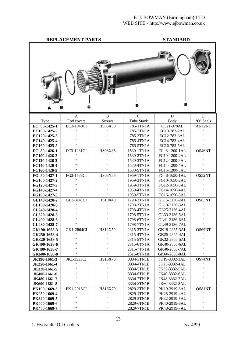
INTRODUCTIONThese oil coolers are also suitable for heat transfer fluids, lubricating, transformer &quenching oils. They are high quality products incorporating the best materials and thelatest technical features. The tube stack is fully floating so that thermal stresses areminimised and it can be easily removed should cleaning be necessary.

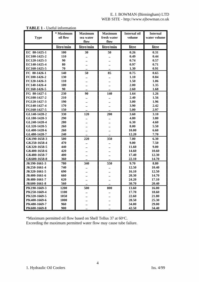
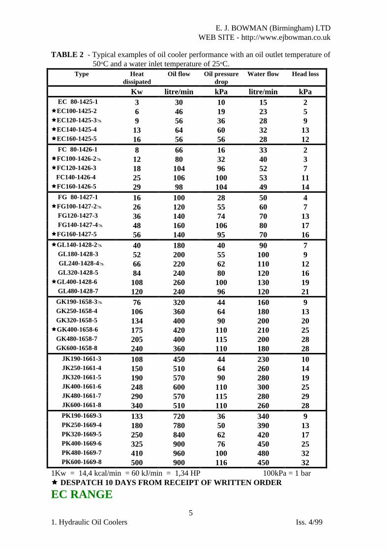
SELECTIONListed in TABLE 1 are typical examples of oil cooler performance. This information isonly intended to provide a general basis for selection, graphs are available (on request)which show how heat dissipation and pressure losses vary with oil and water flow.Alternatively we can select by computer, the size of oil cooler required from thefollowing information :-

Oil type or its viscosity at a specified temperature cSt at ºCOil flow l/minRequired oil outlet temperature ºCHeat to be dissipated kWTemperature of cooling water ºC

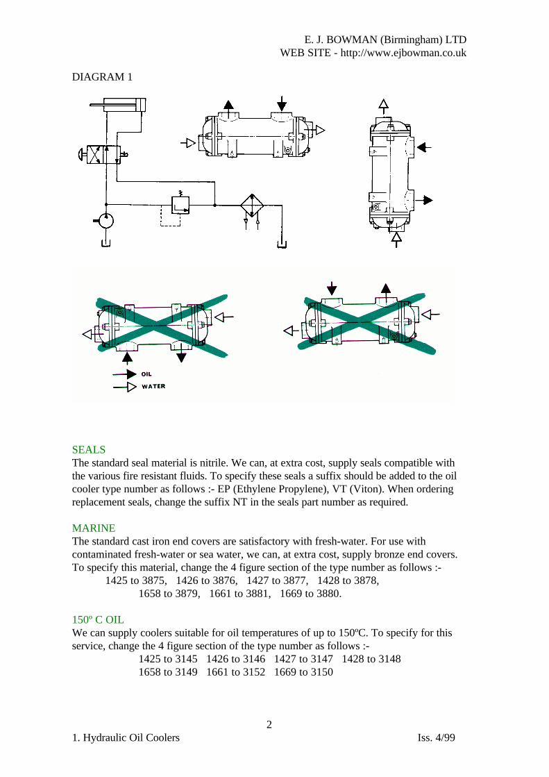
INSTALLATIONThe oil coolers should be mounted as shown below to ensure that they operate full ofwater and should be connected for counter flow. If a water control valve is used it shouldbe of the modulating type and fitted on the inlet side, so that the cooler is notunnecessarily pressurised with water when the system is shut down. Care must be takennot to exceed the recommended water flow rates, and the pH of the water should bebetween 7.2 and 7.8. For hydraulic applications, the oil cooler should usually be in thereturn pipe to the tank as shown in Diagram 1, but on installations where this is subject toviolent fluctuations in flow and pressure, it may be advisable to connect the cooler into aseparate circuit with its own pump. It is good practice for the oil pressure in the cooler tobe higher than the water pressure, so that should a leak occur, the oil will not becontaminated with water.

E. J. BOWMAN (Birmingham) LTDWEB SITE - http://www.ejbowman.co.uk

21. Hydraulic Oil Coolers Iss. 4/99

DIAGRAM 1

SEALSThe standard seal material is nitrile. We can, at extra cost, supply seals compatible withthe various fire resistant fluids. To specify these seals a suffix should be added to the oilcooler type number as follows :- EP (Ethylene Propylene), VT (Viton). When orderingreplacement seals, change the suffix NT in the seals part number as required.

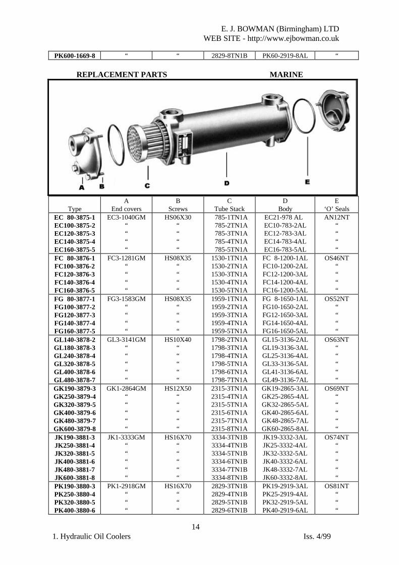
MARINEThe standard cast iron end covers are satisfactory with fresh-water. For use withcontaminated fresh-water or sea water, we can, at extra cost, supply bronze end covers.To specify this material, change the 4 figure section of the type number as follows :-

1425 to 3875, 1426 to 3876, 1427 to 3877, 1428 to 3878,1658 to 3879, 1661 to 3881, 1669 to 3880.

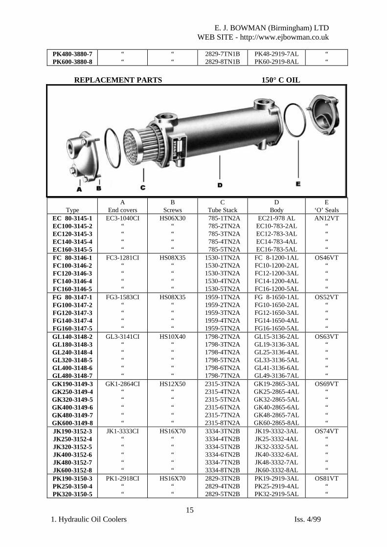
150º C OILWe can supply coolers suitable for oil temperatures of up to 150ºC. To specify for thisservice, change the 4 figure section of the type number as follows :-

1425 to 3145 1426 to 3146 1427 to 3147 1428 to 31481658 to 3149 1661 to 3152 1669 to 3150

E. J. BOWMAN (Birmingham) LTDWEB SITE - http://www.ejbowman.co.uk

31. Hydraulic Oil Coolers Iss. 4/99

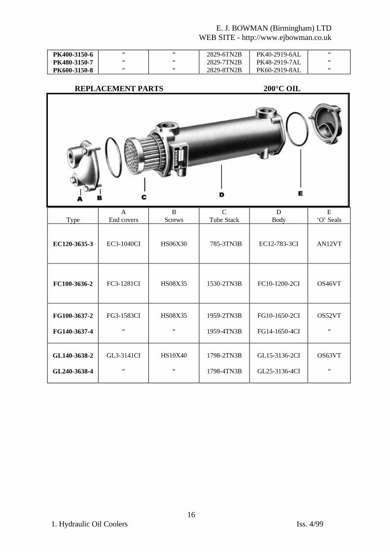
200ºC OILIn addition, we have a limited range of oil coolers suitable for use with oil or heattransfer fluids up to 200ºC. These oil coolers have a cast iron shell, viton seals and aspecial tube stack. To specify for this service, change the 4 figure section of the typenumber to the following :-

1425 to 3635 1426 to 3636 1427 to 3637 1428 to 3638This particular option is only available with coolers marked @ in the “Type” column inTABLE 2 below.

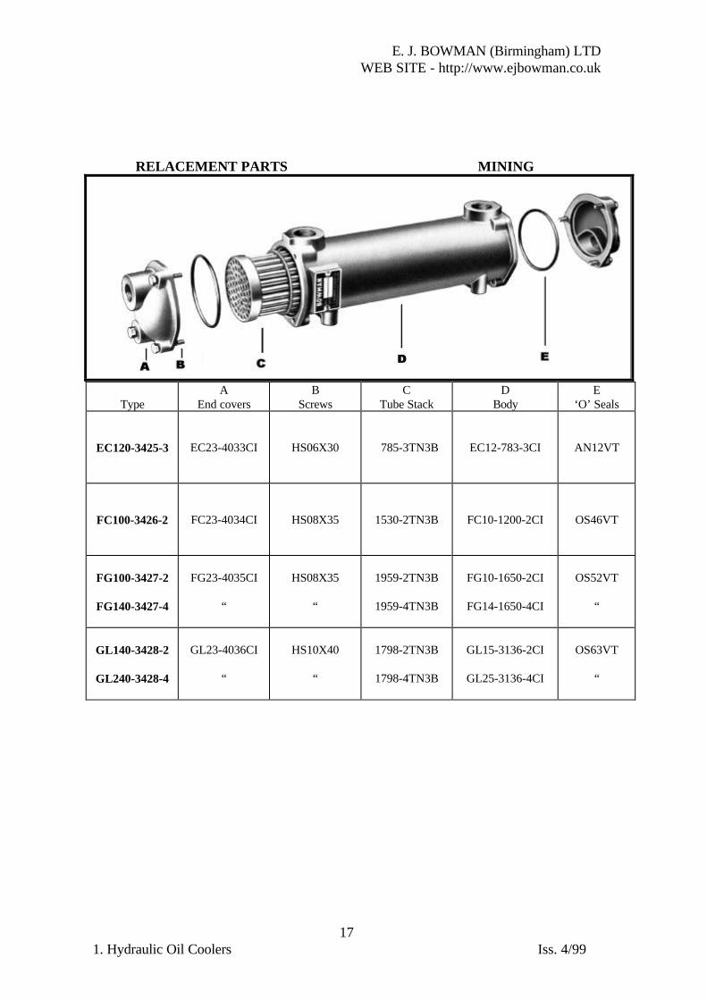
MININGWe have a limited range of oil coolers suitable for underground mining applications andwater pressures up to 35 bar. These oil coolers have a cast iron shell, viton seals and aspecial tube stack with cupro-nickel tube. To specify for this service, change the 4 figuresection of the type number as follows :-

1425 to 3425 1426 to 3426 1427 to 3427 1428 to 3428This option is only available with coolers marked @ in the “Type” column in TABLE 2below.

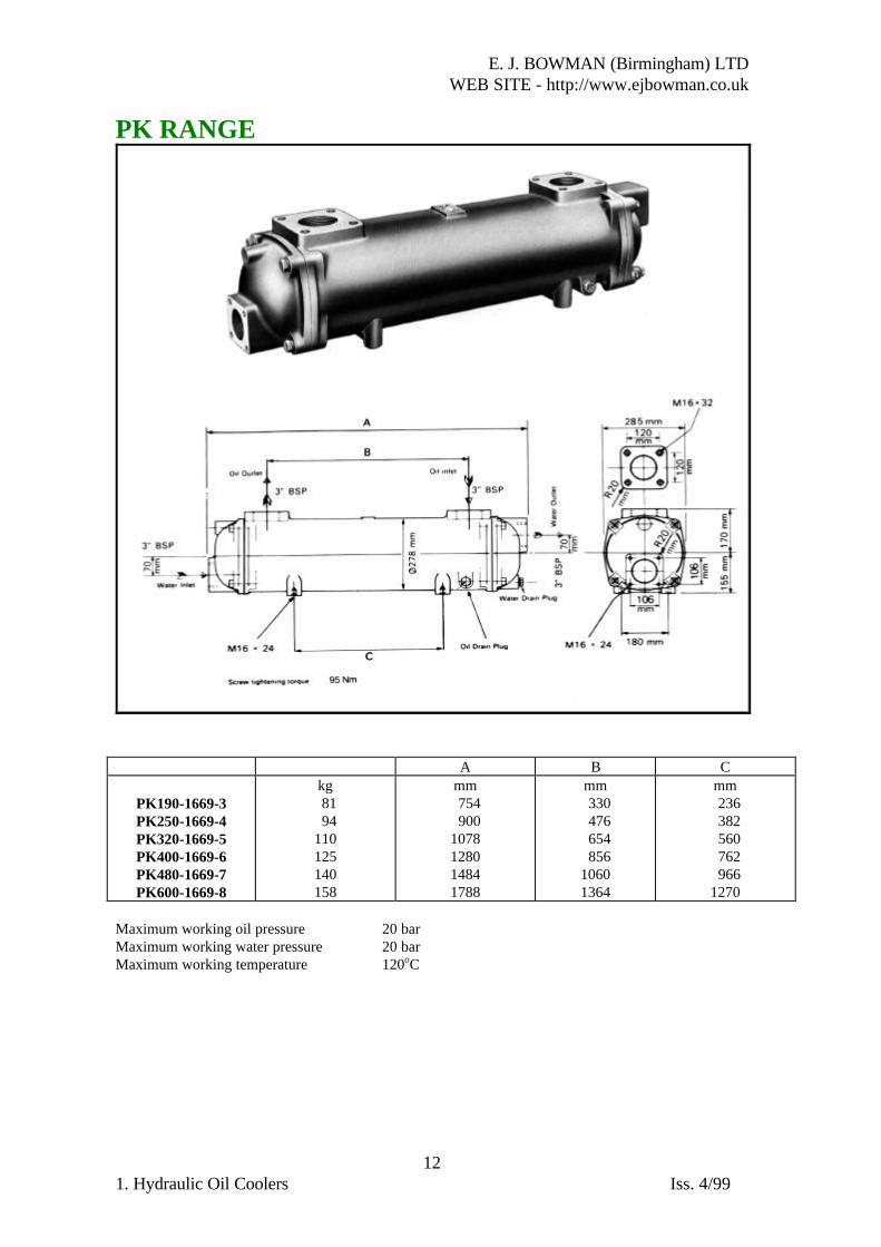
GENERALPlease contact us for applications not covered by our published information. We can alsoadvise on the best method of installing coolers particularly for unusual or criticalapplications. If a single unit is too small, multiple units can be connected either in seriesor in parallel according to the oil flow rate. We can also supply the PK range of coolerswith 4” ports and special high flow tube stacks suitable for oil flow rates up to 1400l/min.

E. J. BOWMAN (Birmingham) LTDWEB SITE - http://www.ejbowman.co.uk

41. Hydraulic Oil Coolers Iss. 4/99

TABLE 1 - Useful information

Type* Maximum

oil flowMaximumsea water

flow

Maximumfresh water

flow

Internal oilvolume

Internalwater volume

litre/min litre/min litre/min litre litreEC 80-1425-1 100 30 50 0.26 0.31EC100-1425-2 110 .. .. 0.49 0.44EC120-1425-3 90 .. .. 0.74 0.57EC140-1425-4 80 .. .. 0.97 0.71EC160-1425-5 70 .. .. 1.30 0.91FC 80-1426-1 140 50 85 0.75 0.65FC100-1426-2 130 .. .. 1.10 0.84FC120-1426-3 110 .. .. 1.50 1.06FC140-1426-4 100 .. .. 2.00 1.35FC160-1426-5 90 .. .. 2.60 1.68FG 80-1427-1 230 90 140 1.64 1.26FG100-1427-2 210 .. .. 2.40 1.56FG120-1427-3 190 .. .. 3.00 1.96FG140-1427-4 170 .. .. 3.90 2.42FG160-1427-5 150 .. .. 5.00 2.97GL140-1428-2 330 120 200 3.60 3.10GL180-1428-3 290 .. .. 4.80 3.80GL240-1428-4 280 .. .. 6.30 4.60GL320-1428-5 260 .. .. 8.00 5.50GL400-1428-6 260 .. .. 10.00 6.60GL480-1428-7 240 .. .. 12.20 7.70GK190-1658-3 500 220 350 7.00 6.30GK250-1658-4 470 .. .. 9.00 7.50GK320-1658-5 440 .. .. 11.60 9.00GK400-1658-6 420 .. .. 14.60 10.60GK480-1658-7 400 .. .. 17.40 12.30GK600-1658-8 360 .. .. 22.10 14.70JK190-1661-3 780 340 550 9.70 8.80JK250-1661-4 740 .. .. 12.50 10.40JK320-1661-5 690 .. .. 16.10 12.50JK400-1661-6 660 .. .. 20.30 14.70JK480-1661-7 620 .. .. 24.20 17.10JK600-1661-8 560 .. .. 30.70 20.40PK190-1669-3 1200 500 800 13.60 16.00PK250-1669-4 1100 .. .. 17.70 18.60PK320-1669-5 1050 .. .. 22.60 21.80PK400-1669-6 1000 .. .. 28.50 25.30PK480-1669-7 960 .. .. 34.00 29.00PK600-1669-8 900 .. .. 42.50 34.40

*Maximum permitted oil flow based on Shell Tellus 37 at 60°C.Exceeding the maximum permitted water flow may cause tube failure.

E. J. BOWMAN (Birmingham) LTDWEB SITE - http://www.ejbowman.co.uk

51. Hydraulic Oil Coolers Iss. 4/99

TABLE 2 - Typical examples of oil cooler performance with an oil outlet temperature of50°C and a water inlet temperature of 25°C.

Type Heatdissipated

Oil flow Oil pressuredrop

Water flow Head loss

Kw litre/min kPa litre/min kPa EC 80-1425-1 3 30 10 15 2êEC100-1425-2 6 46 19 23 5êEC120-1425-3@ 9 56 36 28 9êEC140-1425-4 13 64 60 32 13êEC160-1425-5 16 56 56 28 12 FC 80-1426-1 8 66 16 33 2êFC100-1426-2@ 12 80 32 40 3êFC120-1426-3 18 104 96 52 7 FC140-1426-4 25 106 100 53 11êFC160-1426-5 29 98 104 49 14 FG 80-1427-1 16 100 28 50 4êFG100-1427-2@ 26 120 55 60 7 FG120-1427-3 36 140 74 70 13 FG140-1427-4@ 48 160 106 80 17êFG160-1427-5 56 140 95 70 16êGL140-1428-2@ 40 180 40 90 7 GL180-1428-3 52 200 55 100 9

GL240-1428-4@ 66 220 62 110 12 GL320-1428-5 84 240 80 120 16êGL400-1428-6 108 260 100 130 19 GL480-1428-7 120 240 96 120 21 GK190-1658-3@ 76 320 44 160 9 GK250-1658-4 106 360 64 180 13 GK320-1658-5 134 400 90 200 20êGK400-1658-6 175 420 110 210 25 GK480-1658-7 205 400 115 200 28 GK600-1658-8 240 360 110 180 28

JK190-1661-3 108 450 44 230 10JK250-1661-4 150 510 64 260 14JK320-1661-5 190 570 90 280 19JK400-1661-6 248 600 110 300 25JK480-1661-7 290 570 115 280 29JK600-1661-8 340 510 110 260 28PK190-1669-3 133 720 36 340 9PK250-1669-4 180 780 50 390 13PK320-1669-5 250 840 62 420 17PK400-1669-6 325 900 76 450 25PK480-1669-7 410 960 100 480 32PK600-1669-8 500 900 116 450 32

1Kw = 14,4 kcal/min = 60 kJ/min = 1,34 HP 100kPa = 1 barêê DESPATCH 10 DAYS FROM RECEIPT OF WRITTEN ORDER

EC RANGE

E. J. BOWMAN (Birmingham) LTDWEB SITE - http://www.ejbowman.co.uk

61. Hydraulic Oil Coolers Iss. 4/99

A B C D

EC 80-1425-1EC100-1425-2EC120-1425-3EC140-1425-4EC160-1425-5

kg2.43.23.84.85.7

mm174260346444572

mm 60140226324452

mm 60104190288416

BSP½"¾"¾"¾"¾"

Maximum working oil pressure 20 barMaximum working water pressure 20 barMaximum working temperature 120oC

FC RANGE

E. J. BOWMAN (Birmingham) LTDWEB SITE - http://www.ejbowman.co.uk

71. Hydraulic Oil Coolers Iss. 4/99

A B C

FC 80-1426-1FC100-1426-2FC120-1426-3FC140-1426-4FC160-1426-5

kg 5.5 6.3 7.3 9.411.0

mm272358456584730

mm116202300428574

mm104190288288434

Maximum working oil pressure 20 barMaximum working water pressure 20 barMaximum working temperature 120oC

FG RANGE

E. J. BOWMAN (Birmingham) LTDWEB SITE - http://www.ejbowman.co.uk

81. Hydraulic Oil Coolers Iss. 4/99

A B C

FG 80-1427-1FG100-1427-2FG120-1427-3FG140-1427-4FG160-1427-5

kg 8.510.012.014.517.5

mm374472600746924

mm196294422568746

mm 92190318464642

Maximum working oil pressure 20 barMaximum working water pressure 20 barMaximum working temperature 120oC

GL RANGE

E. J. BOWMAN (Birmingham) LTDWEB SITE - http://www.ejbowman.co.uk

91. Hydraulic Oil Coolers Iss. 4/99

A B C

GL140-1428-2GL180-1428-3GL240-1428-4GL320-1428-5GL400-1428-6GL480-1428-7

kg182125303642

mm 502 630 776 95411561360

mm 272 400 546 724 9261130

mm108236382560762966

Maximum working oil pressure 20 barMaximum working water pressure 20 barMaximum working temperature 120oC

GK RANGE

E. J. BOWMAN (Birmingham) LTDWEB SITE - http://www.ejbowman.co.uk

101. Hydraulic Oil Coolers Iss. 4/99

A B C

GK190-1658-3GK250-1658-4GK320-1658-5GK400-1658-6GK480-1658-7GK600-1658-8

kg343946546274

mm 674 820 998120014041708

mm 370 516 694 89611001404

mm 236 382 560 762 9661270

Maximum working oil pressure 20 barMaximum working water pressure 20 barMaximum working temperature 120oC

JK RANGE

E. J. BOWMAN (Birmingham) LTDWEB SITE - http://www.ejbowman.co.uk

111. Hydraulic Oil Coolers Iss. 4/99

A B C

JK190-1661-3JK250-1661-4JK320-1661-5JK400-1661-6JK480-1661-7JK600-1661-8

kg 58 66 78 92105126

mm 704 8501028123014341738

mm 340 486 664 86610701374

mm 236 382 560 762 9661270

Maximum working oil pressure 20 barMaximum working water pressure 20 barMaximum working temperature 120oC

E. J. BOWMAN (Birmingham) LTDWEB SITE - http://www.ejbowman.co.uk

121. Hydraulic Oil Coolers Iss. 4/99

PK RANGE

A B C

PK190-1669-3PK250-1669-4PK320-1669-5PK400-1669-6PK480-1669-7PK600-1669-8

kg 81 94110125140158

mm 754 9001078128014841788

mm 330 476 654 85610601364

mm 236 382 560 762 9661270

Maximum working oil pressure 20 barMaximum working water pressure 20 barMaximum working temperature 120oC

E. J. BOWMAN (Birmingham) LTDWEB SITE - http://www.ejbowman.co.uk

131. Hydraulic Oil Coolers Iss. 4/99

REPLACEMENT PARTS STANDARD

TypeA

End coversB

ScrewsC

Tube StackD

BodyE

‘O’ SealsEC 80-1425-1EC100-1425-2EC120-1425-3EC140-1425-4EC160-1425-5

EC3-1040CI““““

HS06X30““““

785-1TN1A 785-2TN1A 785-3TN1A 785-4TN1A 785-5TN1A

EC21-978ALEC10-783-2ALEC12-783-3ALEC14-783-4ALEC16-783-5AL

AN12NT““““

FC 80-1426-1FC100-1426-2FC120-1426-3FC140-1426-4FC160-1426-5

FC3-1281CI““““

HS08X35““““

1530-1TN1A1530-2TN1A1530-3TN1A1530-4TN1A1530-5TN1A

FC 8-1200-1ALFC10-1200-2ALFC12-1200-3ALFC14-1200-4ALFC16-1200-5AL

OS46NT““““

FG 80-1427-1FG100-1427-2FG120-1427-3FG140-1427-4FG160-1427-5

FG3-1583CI““““

HS08X35““““

1959-1TN1A1959-2TN1A1959-3TN1A1959-4TN1A1959-5TN1A

FG 8-1650-1ALFG10-1650-2ALFG12-1650-3ALFG14-1650-4ALFG16-1650-5AL

OS52NT““““

GL140-1428-2GL180-1428-3GL240-1428-4GL320-1428-5GL400-1428-6GL480-1428-7

GL3-3141CI“““““

HS10X40“““““

1798-2TN1A1798-3TN1A1798-4TN1A1798-5TN1A1798-6TN1A1798-7TN1A

GL15-3136-2ALGL19-3136-3ALGL25-3136-4ALGL33-3136-5ALGL41-3136-6ALGL49-3136-7AL

OS63NT“““““

GK190-1658-3GK250-1658-4GK320-1658-5GK400-1658-6GK480-1658-7GK600-1658-8

GK1-2864CI“““““

HS12X50“““““

2315-3TN1A2315-4TN1A2315-5TN1A2315-6TN1A2315-7TN1A2315-8TN1A

GK19-2865-3ALGK25-2865-4ALGK32-2865-5ALGK40-2865-6ALGK48-2865-7ALGK60-2865-8AL

OS69NT“““““

JK190-1661-3JK250-1661-4JK320-1661-5JK400-1661-6JK480-1661-7JK600-1661-8

JK1-3333CI“““““

HS16X70“““““

3334-3TN1B3334-4TN1B3334-5TN1B3334-6TN1B3334-7TN1B3334-8TN1B

JK19-3332-3ALJK25-3332-4ALJK32-3332-5ALJK40-3332-6ALJK48-3332-7ALJK60-3332-8AL

OS74NT“““““

PK190-1669-3PK250-1669-4PK320-1669-5PK400-1669-6PK480-1669-7

PK1-2918CI““““

HS16X70““““

2829-3TN1B2829-4TN1B2829-5TN1B2829-6TN1B2829-7TN1B

PK19-2919-3ALPK25-2919-4ALPK32-2919-5ALPK40-2919-6ALPK48-2919-7AL

OS81NT““““

E. J. BOWMAN (Birmingham) LTDWEB SITE - http://www.ejbowman.co.uk

141. Hydraulic Oil Coolers Iss. 4/99

PK600-1669-8 “ “ 2829-8TN1B PK60-2919-8AL “

REPLACEMENT PARTS MARINE

TypeA

End coversB

ScrewsC

Tube StackD

BodyE

‘O’ SealsEC 80-3875-1EC100-3875-2EC120-3875-3EC140-3875-4EC160-3875-5

EC3-1040GM““““

HS06X30““““

785-1TN1A 785-2TN1A 785-3TN1A 785-4TN1A 785-5TN1A

EC21-978 ALEC10-783-2ALEC12-783-3ALEC14-783-4ALEC16-783-5AL

AN12NT““““

FC 80-3876-1FC100-3876-2FC120-3876-3FC140-3876-4FC160-3876-5

FC3-1281GM““““

HS08X35““““

1530-1TN1A1530-2TN1A1530-3TN1A1530-4TN1A1530-5TN1A

FC 8-1200-1ALFC10-1200-2ALFC12-1200-3ALFC14-1200-4ALFC16-1200-5AL

OS46NT““““

FG 80-3877-1FG100-3877-2FG120-3877-3FG140-3877-4FG160-3877-5

FG3-1583GM““““

HS08X35““““

1959-1TN1A1959-2TN1A1959-3TN1A1959-4TN1A1959-5TN1A

FG 8-1650-1ALFG10-1650-2ALFG12-1650-3ALFG14-1650-4ALFG16-1650-5AL

OS52NT““““

GL140-3878-2GL180-3878-3GL240-3878-4GL320-3878-5GL400-3878-6GL480-3878-7

GL3-3141GM“““““

HS10X40“““““

1798-2TN1A1798-3TN1A1798-4TN1A1798-5TN1A1798-6TN1A1798-7TN1A

GL15-3136-2ALGL19-3136-3ALGL25-3136-4ALGL33-3136-5ALGL41-3136-6ALGL49-3136-7AL

OS63NT“““““

GK190-3879-3GK250-3879-4GK320-3879-5GK400-3879-6GK480-3879-7GK600-3879-8

GK1-2864GM“““““

HS12X50“““““

2315-3TN1A2315-4TN1A2315-5TN1A2315-6TN1A2315-7TN1A2315-8TN1A

GK19-2865-3ALGK25-2865-4ALGK32-2865-5ALGK40-2865-6ALGK48-2865-7ALGK60-2865-8AL

OS69NT“““““

JK190-3881-3JK250-3881-4JK320-3881-5JK400-3881-6JK480-3881-7JK600-3881-8

JK1-3333GM“““““

HS16X70“““““

3334-3TN1B3334-4TN1B3334-5TN1B3334-6TN1B3334-7TN1B3334-8TN1B

JK19-3332-3ALJK25-3332-4ALJK32-3332-5ALJK40-3332-6ALJK48-3332-7ALJK60-3332-8AL

OS74NT“““““

PK190-3880-3PK250-3880-4PK320-3880-5PK400-3880-6

PK1-2918GM“““

HS16X70“““

2829-3TN1B2829-4TN1B2829-5TN1B2829-6TN1B

PK19-2919-3ALPK25-2919-4ALPK32-2919-5ALPK40-2919-6AL

OS81NT“““

E. J. BOWMAN (Birmingham) LTDWEB SITE - http://www.ejbowman.co.uk

151. Hydraulic Oil Coolers Iss. 4/99

PK480-3880-7PK600-3880-8

““

““

2829-7TN1B2829-8TN1B

PK48-2919-7ALPK60-2919-8AL

““

REPLACEMENT PARTS 150° C OIL

TypeA

End coversB

ScrewsC

Tube StackD

BodyE

‘O’ SealsEC 80-3145-1EC100-3145-2EC120-3145-3EC140-3145-4EC160-3145-5

EC3-1040CI““““

HS06X30““““

785-1TN2A 785-2TN2A 785-3TN2A 785-4TN2A 785-5TN2A

EC21-978 ALEC10-783-2ALEC12-783-3ALEC14-783-4ALEC16-783-5AL

AN12VT““““

FC 80-3146-1FC100-3146-2FC120-3146-3FC140-3146-4FC160-3146-5

FC3-1281CI““““

HS08X35““““

1530-1TN2A1530-2TN2A1530-3TN2A1530-4TN2A1530-5TN2A

FC 8-1200-1ALFC10-1200-2ALFC12-1200-3ALFC14-1200-4ALFC16-1200-5AL

OS46VT““““

FG 80-3147-1FG100-3147-2FG120-3147-3FG140-3147-4FG160-3147-5

FG3-1583CI““““

HS08X35““““

1959-1TN2A1959-2TN2A1959-3TN2A1959-4TN2A1959-5TN2A

FG 8-1650-1ALFG10-1650-2ALFG12-1650-3ALFG14-1650-4ALFG16-1650-5AL

OS52VT““““

GL140-3148-2GL180-3148-3GL240-3148-4GL320-3148-5GL400-3148-6GL480-3148-7

GL3-3141CI“““““

HS10X40“““““

1798-2TN2A1798-3TN2A1798-4TN2A1798-5TN2A1798-6TN2A1798-7TN2A

GL15-3136-2ALGL19-3136-3ALGL25-3136-4ALGL33-3136-5ALGL41-3136-6ALGL49-3136-7AL

OS63VT“““““

GK190-3149-3GK250-3149-4GK320-3149-5GK400-3149-6GK480-3149-7GK600-3149-8

GK1-2864CI“““““

HS12X50“““““

2315-3TN2A2315-4TN2A2315-5TN2A2315-6TN2A2315-7TN2A2315-8TN2A

GK19-2865-3ALGK25-2865-4ALGK32-2865-5ALGK40-2865-6ALGK48-2865-7ALGK60-2865-8AL

OS69VT“““““

JK190-3152-3JK250-3152-4JK320-3152-5JK400-3152-6JK480-3152-7JK600-3152-8

JK1-3333CI“““““

HS16X70“““““

3334-3TN2B3334-4TN2B3334-5TN2B3334-6TN2B3334-7TN2B3334-8TN2B

JK19-3332-3ALJK25-3332-4ALJK32-3332-5ALJK40-3332-6ALJK48-3332-7ALJK60-3332-8AL

OS74VT“““““

PK190-3150-3PK250-3150-4PK320-3150-5

PK1-2918CI““

HS16X70““

2829-3TN2B2829-4TN2B2829-5TN2B

PK19-2919-3ALPK25-2919-4ALPK32-2919-5AL

OS81VT““

E. J. BOWMAN (Birmingham) LTDWEB SITE - http://www.ejbowman.co.uk

161. Hydraulic Oil Coolers Iss. 4/99

PK400-3150-6PK480-3150-7PK600-3150-8

“““

“““

2829-6TN2B2829-7TN2B2829-8TN2B

PK40-2919-6ALPK48-2919-7ALPK60-2919-8AL

“““

REPLACEMENT PARTS 200°C OIL

TypeA

End coversB

ScrewsC

Tube StackD

BodyE

‘O’ Seals

EC120-3635-3 EC3-1040CI HS06X30 785-3TN3B EC12-783-3CI AN12VT

FC100-3636-2 FC3-1281CI HS08X35 1530-2TN3B FC10-1200-2CI OS46VT

FG100-3637-2

FG140-3637-4

FG3-1583CI

HS08X35

1959-2TN3B

1959-4TN3B

FG10-1650-2CI

FG14-1650-4CI

OS52VT

GL140-3638-2

GL240-3638-4

GL3-3141CI

HS10X40

1798-2TN3B

1798-4TN3B

GL15-3136-2CI

GL25-3136-4CI

OS63VT

E. J. BOWMAN (Birmingham) LTDWEB SITE - http://www.ejbowman.co.uk

171. Hydraulic Oil Coolers Iss. 4/99

RELACEMENT PARTS MINING

TypeA

End coversB

ScrewsC

Tube StackD

BodyE

‘O’ Seals

EC120-3425-3 EC23-4033CI HS06X30 785-3TN3B EC12-783-3CI AN12VT

FC100-3426-2 FC23-4034CI HS08X35 1530-2TN3B FC10-1200-2CI OS46VT

FG100-3427-2

FG140-3427-4

FG23-4035CI

HS08X35

1959-2TN3B

1959-4TN3B

FG10-1650-2CI

FG14-1650-4CI

OS52VT

GL140-3428-2

GL240-3428-4

GL23-4036CI

HS10X40

1798-2TN3B

1798-4TN3B

GL15-3136-2CI

GL25-3136-4CI

OS63VT

E. J. BOWMAN (Birmingham) LTDWEB SITE - http://www.ejbowman.co.uk

181. Hydraulic Oil Coolers Iss. 4/99

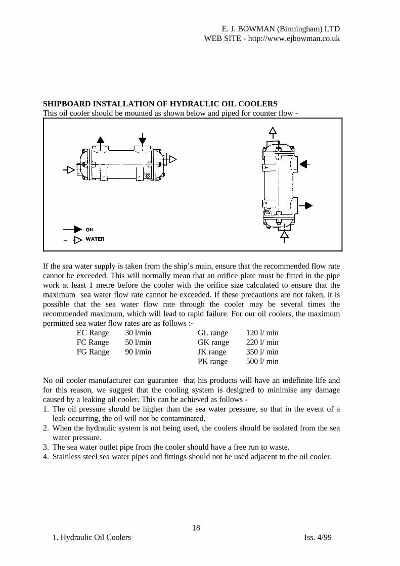
SHIPBOARD INSTALLATION OF HYDRAULIC OIL COOLERSThis oil cooler should be mounted as shown below and piped for counter flow -

If the sea water supply is taken from the ship’s main, ensure that the recommended flow ratecannot be exceeded. This will normally mean that an orifice plate must be fitted in the pipework at least 1 metre before the cooler with the orifice size calculated to ensure that themaximum sea water flow rate cannot be exceeded. If these precautions are not taken, it ispossible that the sea water flow rate through the cooler may be several times therecommended maximum, which will lead to rapid failure. For our oil coolers, the maximumpermitted sea water flow rates are as follows :-

EC Range 30 l/min GL range 120 l/ minFC Range 50 l/min GK range 220 l/ minFG Range 90 l/min JK range 350 l/ min

PK range 500 l/ min

No oil cooler manufacturer can guarantee that his products will have an indefinite life andfor this reason, we suggest that the cooling system is designed to minimise any damagecaused by a leaking oil cooler. This can be achieved as follows -1. The oil pressure should be higher than the sea water pressure, so that in the event of a

leak occurring, the oil will not be contaminated.2. When the hydraulic system is not being used, the coolers should be isolated from the sea

water pressure.3. The sea water outlet pipe from the cooler should have a free run to waste.4. Stainless steel sea water pipes and fittings should not be used adjacent to the oil cooler.

E. J. BOWMAN (Birmingham) LTDWEB SITE - http://www.ejbowman.co.uk

191. Hydraulic Oil Coolers Iss. 4/99

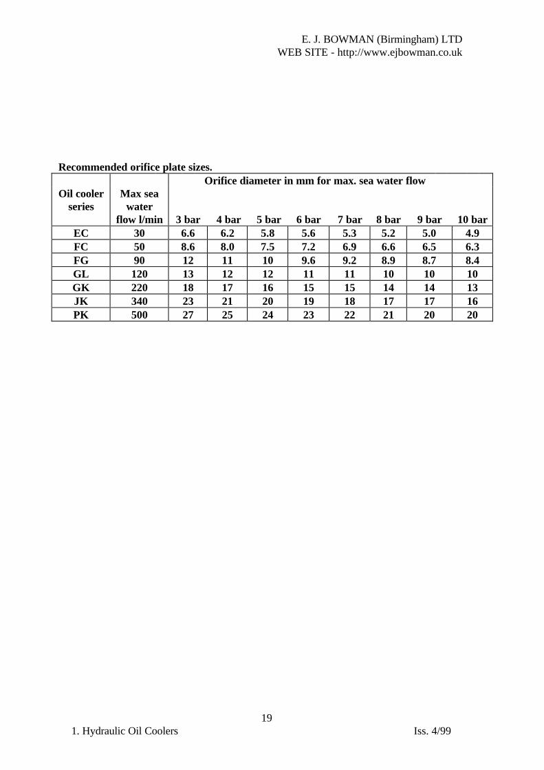
Recommended orifice plate sizes.Orifice diameter in mm for max. sea water flow

Oil coolerseries

Max seawater

flow l/min 3 bar 4 bar 5 bar 6 bar 7 bar 8 bar 9 bar 10 barEC 30 6.6 6.2 5.8 5.6 5.3 5.2 5.0 4.9FC 50 8.6 8.0 7.5 7.2 6.9 6.6 6.5 6.3FG 90 12 11 10 9.6 9.2 8.9 8.7 8.4GL 120 13 12 12 11 11 10 10 10GK 220 18 17 16 15 15 14 14 13JK 340 23 21 20 19 18 17 17 16PK 500 27 25 24 23 22 21 20 20


Recommended