66
HYDRAULIC STEERING SYSTEMS

H Y D R A U L I C S T E E R I N G S Y S T E M S


Company Profile and Introduction 2-5
Hydraulic Steering Systems 6-7Composition and Working Principle
Helm Pumps 8-13
Heavy Duty Helm Pumps 14-16
Systems 1-14 17-30
Inboard Steering Cylinders 31-33
Inboard Heavy Duty Cylinders 34-36
Manual Inboard Steering SystemsOrder Guide 37
Autopilot Power Units 38-42
Autopilot Order Guide 43-44
Power-Assisted Inboard Steering Systems Features and Working Principle 45-46
Power-Assisted Inboard Cylinders 47-49
Power-Assisted Electro-Hydraulic Power Units 50
Power-Assisted Steering System Applications and Systems 51-55
Power-Assisted Steering System: Big Range 56
Steering System for Catamarans 57
Hydrostatic Steering Systems with Engine-Driven Pumps 58
Accessories 59-60
Fittings 61-62
International Distributors back cover
INDEX
NOTE: Twin Disc Srl declines any liability for possible mistakes in this catalogue due to printing errors and reserves the right to make any modification that is considered to be necessary or useful for its products. Publishing rights, trade marks, part numbers and photographs present on this catalogue are Twin Disc Srl property or it has the necessary authorization to use them. So, all rights are reserved and any reproduction, even partial, is forbidden. Our products cannot be installed on racing boats without our previous authorization.
3

4
High Quality, Complete Solutions

3
Production plant in Limite sull’Arno
Throughout our nearly sixty years of experience, BCS has become a leading company in the production and worldwide distribution of high quality marine equipment. The acquisition by Twin Disc, Inc. – leader in several different areas such as marine and industrial, heavy duty transmissions and the oil extraction industry – has consolidated its position on the market as part of a multinational group.
Twin Disc SRL combines BCS, BCS Service, Twin Disc Technodrive and Twin Disc Propulsion. Twin Disc SRL is also supported by a sister-company, Rolla SP Propellers.
Global ‘Package’Twin Disc SRL offers to boat builders and design engineers a complete ”package” of products, from propulsion systems to gearboxes and transmissions up to control and steering systems, together with customized solutions and efficient technical support. Also global customer service for the development and realization of the whole kinematics system.
A dynamic team of engineers, technicians and professional people is devoted to support the customer in any step: from concept of the project to the planning, through prototype development and design definition, up to bench and field testing, production, assembly, installation and service also on board.
Twin Disc SRL works alongside the customer every day. We have established a unique worldwide system dedicated to the marine industry based on our ability to acknowledge and anticipate market requests, the certified reliability of our products, skilled service and the continuous research of technological innovation.
The production plant of Limite sull’ Arno produces equipment covering several application fields: Hydraulic and electronic steering systems, complete shaft lines for boats up to 40 meters, trim tab systems in stainless steel or aluminum, electric and hydraulic bow and stern thrusters, electrohydraulic gangways and side ladders for large applications, as well as a large variety of stainless steel hydraulic actuators and multi-function electrohydraulic power units.

6
From concept to production: prototype development, care for design, field testing, product definition

5
Twin Disc SRL is certified by Registro Italiano Navale (RINA) according to the requirements of the standards UNI EN ISO 9001:2000.
All the management and production processes of the company, from the material research and the design of products, to the planning of the production cycles, checking tests and shipping management, undergo the constant verification of the strictest quality criteria in order to guarantee the highest reliability level.
As a result of more than 50 years of experience, our steering systems are a synthesis between selected materials, innovative design and state-of-art technical solutions.
All components are built with high precision systems and tooling and meet the requirements of the best survey authorities such as: Rina Lloyd’s Register, ABS, Bureau Veritas etc. As a further guarantee of efficiency and durability, certificates for special applications are also available upon request.
Conforming with “the Standard 94/25/CE”, as amended by “the Standard 2003/44/CE”, and also included in the Type Accepted of Program NMMA, the Twin Disc line of hydraulic pumps and cylinders covers any type of application: outboard, stern-drives and inboard systems for pleasure and commercial vessels.
6
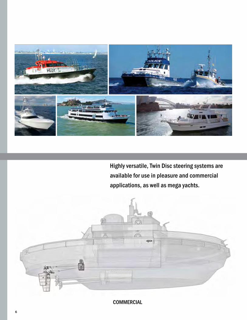
Highly versatile, Twin Disc steering systems are available for use in pleasure and commercial applications, as well as mega yachts.
COMMERCIAL

7
HYDRAULIC STEERING SYSTEMSCoMPoSITIoN AND WoRKING PRINCIPLE
In order to get the best control with the minimum effort, the steering system must match the specific vessel’s requirements.A standard steering system in its basic composition includes major elements such as:
• Hydraulic helm pump of the axial piston type, which pumps oil into the system each time the steering wheel is turned. The pump is provided with a non-return (lock) valve to prevent any movement of the rudder or the outboard engine when the pump is not controlled, and with a relief valve to protect the steering system from any sudden and excessive pressure increase.
• Hydraulic cylinder, which is the real rudder actuator and determines the power of the system. It is extremely important to select the right cylinder model suitable for the torque required.
The pump and the cylinder are connected together by means of:
• Rigid or flexible hoses suitable for hydraulic applications and sized according to the pump displacement. The rigid piping guarantees the best steering performances, but it is also possible to use flexible hose for rudder torque not higher than 290 Kg/m (24.675 in/lb).
To satisfy different needs, or adapt to specific solutions, this basic configuration can be integrated with many other steering components such as:
• Hydraulic helm pumps for additional control stations• Autopilot power unit, available in a wide range of
displacements for combination with steering cylinders having a volume up to 3900 cc
• Many types of valve or accessories (see pages 59-60)
The working principle of the basic steering system is very simple:A. Turning the steering wheel in the direction desired sends an oil flow from the helm pump to the steering cylinder.B. This flow, which enters the cylinder, moves the piston, as well as the rod connected to the tiller arm, thus causing the rudder to rotate.C. Oil displaced from the opposite side of the cylinder flows
back to the helm pump.D. To rotate the rudder in the opposite direction, simply turn
the helm pump the other way.
Note: In case of dual station, the oil cap of the pilot house shall be closed. If a power unit with automatic filling is installed both caps shall be closed.
PLEASURE CRAFT
8
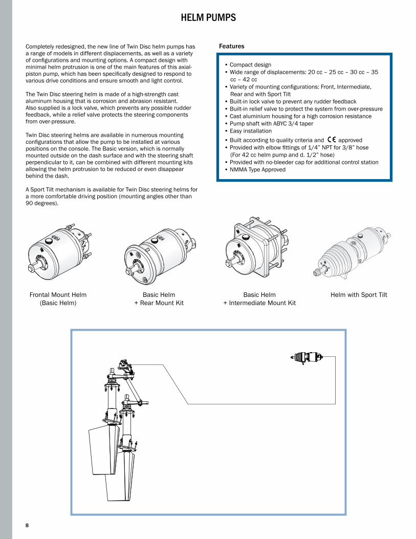
Frontal Mount Helm(Basic Helm)
Basic Helm + Rear Mount Kit
Basic Helm + Intermediate Mount Kit
Helm with Sport Tilt
HELM PUMPS
Completely redesigned, the new line of Twin Disc helm pumps has a range of models in different displacements, as well as a variety of configurations and mounting options. A compact design with minimal helm protrusion is one of the main features of this axial-piston pump, which has been specifically designed to respond to various drive conditions and ensure smooth and light control.
The Twin Disc steering helm is made of a high-strength cast aluminum housing that is corrosion and abrasion resistant. Also supplied is a lock valve, which prevents any possible rudder feedback, while a relief valve protects the steering components from over-pressure.
Twin Disc steering helms are available in numerous mounting configurations that allow the pump to be installed at various positions on the console. The Basic version, which is normally mounted outside on the dash surface and with the steering shaft perpendicular to it, can be combined with different mounting kits allowing the helm protrusion to be reduced or even disappear behind the dash.
A Sport Tilt mechanism is available for Twin Disc steering helms for a more comfortable driving position (mounting angles other than 90 degrees).
Features
• Compact design • Wide range of displacements: 20 cc – 25 cc – 30 cc – 35
cc – 42 cc• Variety of mounting configurations: Front, Intermediate,
Rear and with Sport Tilt• Built-in lock valve to prevent any rudder feedback• Built-in relief valve to protect the system from over-pressure• Cast aluminium housing for a high corrosion resistance • Pump shaft with ABYC 3/4 taper• Easy installation• Built according to quality criteria and approved• Provided with elbow fittings of 1/4” NPT for 3/8” hose (For 42 cc helm pump and d. 1/2” hose)• Provided with no-bleeder cap for additional control station• NMMA Type Approved

9
order Guide
HELM PUMP
Model Displacement Code
P20BAPP20BA
20 cc/rev IT21173IT161921.22 cu.in/rev
P30BAPP30BA
30 cc/rev IT21174IT161931.83 cu.in/rev
P42BAPP42BA
42cc/rev IT21175IT161942.56 cu.in/rev
HELM PUMPS 20 CC - 30 CC - 42 CC• frontal mounting - BaSic helm Mounting Configuration
Frontal Mounting
Model Mounting Configuration
Non- return valve
Relief valve Displacement # of
pistonsRelief valve
setting pressure Fittings included Min. wheel diameter
Max. wheel diameter Weight
P20BAPP20BA Frontal Yes Yes
20 cc/rev 5
70 bar 1/4”NPTF - 3/8” D.E.G1/4’’ - hose d. 10
350 mm 711 mm 2.6 Kg
1.22 cu.in/rev 1000 psi 13,78 in. 28 in. 5.8 lb
P30BAPP30BA Frontal Yes Yes
30 cc/rev5
70 bar1/4”NPTF - 3/8” D.E.G1/4’’ - hose d. 10
350 mm 711 mm 3.0 Kg
1.83 cu.in/rev 1000 psi 13,78 in. 28 in. 6.7 lb
P42BAPP42BA Frontal Yes Yes
42 cc/rev
7
70 bar 1/4”NPTF - 3/8” D.E. 1/4”NPTF - 1/2” D.E.G1/4’’ - hose d. 10G1/4’’ - hose d. 12
450 mm 711 mm 3.0 Kg
2.56 cu.in/rev 1000 psi 17,72 in. 28 in. 6.7 lb
NOTE: The Twin Disc 20 cc-30 cc-42 cc helm pumps are provided with inch fittings. Versions with metric fittings are also available.
Nϒ 4 M6 (0,24”)
67 mm (2,6”)
ø 76 mm (3”)
67 mm (2,6”)
31,5 mm (1,25”)
20 mm (0,79”)
203,5 mm (8”)109 mm (4,25”)
8,5 mm (0,35”)
54 mm (2,13”)
45 mm (1,8”)
ø25 mm (0,98”)
ø111 mm (4,35”)
5 mm (0,2”) ø115 mm (4,5”)2,386
ϒ
(2ϒ23’9,5”)
19,74 mm (0,78”)
TECHNICAL SPECIFICATIONS

12
20 mm (0,79”)2 mm (0,08”)
5 mm
(0,
2”)
ø130 mm (5,12”)
57 mm(2,24”)
40,5
mm
(1,5
9”)
38 m
m (1
,50”
)
59 mm (2,4”)
31,5 mm (1,24”)
2,386ϒ
2ϒ23’9,5”
12 mm (0,47”)250 mm (9,84”)
106 mm (4,17”)53 mm(2,09”)
30 - 32 mm(1,17” - 1,26”)
ø115
mm
(4,5
3”)
Nϒ3
M8
ø30
m (
1,18
”)
19,74 mm (0,78”)
Basic Helm
Rear mount kitmod. MK30
ModelMounting Configura-
tion
Non-return valve
Relief valve
Displace-ment
# of pistons
Relief valve setting pressure Fittings included Min. wheel
diameterMax. wheel diameter Weight
P20BAP + MK30P20BA + MK30 Rear Yes Yes
20 cc/rev5
70 bar 1/4”NPTF - 3/8” D.E.G1/4’’ - hose d. 10
350 mm 711 mm 2.6 Kg1.22 cu.in/
rev 1000 psi 13,78 in. 28 in. 5.8 lb
P30BAP + MK30P30BA + MK30 Rear Yes Yes
30 cc/rev5
70 bar 1/4”NPTF - 3/8” D.E.G1/4’’ - hose d. 10
350 mm 711 mm 3.0 Kg1.83 cu.in/
rev 1000 psi 13,78 in. 28 in. 6.7 lb
P42BAP + MK30P42BA + MK30 Rear Yes Yes
42 cc/rev
7
70 bar 1/4”NPTF - 3/8” D.E.1/4”NPTF - 1/2” D.E.G1/4’’ - hose d. 10G1/4’’ - hose d. 10
450 mm 711 mm 3.0 Kg
2.56 cu.in/rev 1000 psi 17,72 in. 28 in. 6.7 lb
order guide
HELM PUMP
Model Displacement Code
P20BAP + Kit MK30P20BA + Kit MK30
20 cc/rev IT21173+IT16198IT16192+IT161981.22 cu.in/rev
P30BAP + Kit MK30P30BA + Kit MK30
30 cc/rev IT21174+IT16198IT16193+IT161981.83 cu.in/rev
P42BAP + Kit MK30P42BA + Kit MK30
42 cc/rev IT21175+IT16198IT16194+IT161982.56 cu.in/rev
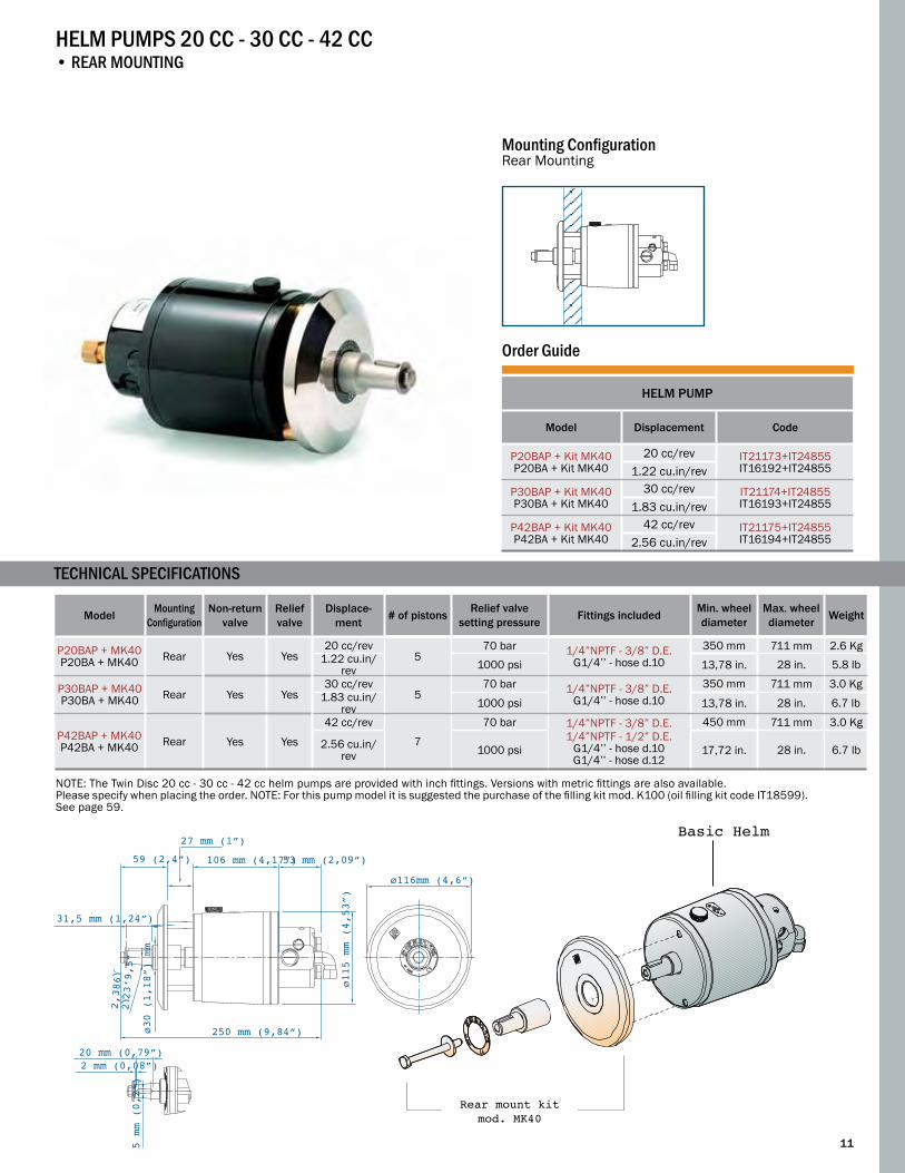
HELM PUMPS 20 CC - 30 CC - 42 CC• rear mounting
mounting configurationRear Mounting
TECHNICAL SPECIFICATIONS
NOTE: The Twin Disc 20 cc - 30 cc - 42 cc helm pumps are provided with inch fittings. Versions with metric fittings are also available. Please specify when placing the order. For this pump model it is suggested the purchase of the filling kit mod. K100 (oil filling kit code IT18599). See page 59.
10
Rear mount kitmod. MK30
20 mm (0,79”)2 mm (0,08”)
5 mm
(0,
2”)
ø116mm (4,6”)
59 (2,4”)
31,5 mm (1,24”)
2,386ϒ
2ϒ23’9,5”
250 mm (9,84”)
106 mm (4,17”)53 mm (2,09”)
ø115
mm
(4,5
3”)
ø30
(1,1
8”)
mm
27 mm (1”)
Model Mounting Configuration
Non-return valve
Relief valve
Displace-ment # of pistons Relief valve
setting pressure Fittings included Min. wheel diameter
Max. wheel diameter Weight
P20BAP + MK40P20BA + MK40 Rear Yes Yes
20 cc/rev5
70 bar 1/4”NPTF - 3/8” D.E.G1/4’’ - hose d.10
350 mm 711 mm 2.6 Kg1.22 cu.in/
rev 1000 psi 13,78 in. 28 in. 5.8 lb
P30BAP + MK40P30BA + MK40 Rear Yes Yes
30 cc/rev5
70 bar 1/4”NPTF - 3/8” D.E.G1/4’’ - hose d.10
350 mm 711 mm 3.0 Kg1.83 cu.in/
rev 1000 psi 13,78 in. 28 in. 6.7 lb
P42BAP + MK40P42BA + MK40 Rear Yes Yes
42 cc/rev
7
70 bar 1/4”NPTF - 3/8” D.E.1/4”NPTF - 1/2” D.E.
G1/4’’ - hose d.10G1/4’’ - hose d.12
450 mm 711 mm 3.0 Kg
2.56 cu.in/rev 1000 psi 17,72 in. 28 in. 6.7 lb
order guide
HELM PUMP
Model Displacement Code
P20BAP + Kit MK40P20BA + Kit MK40
20 cc/rev IT21173+IT24855IT16192+IT248551.22 cu.in/rev
P30BAP + Kit MK40P30BA + Kit MK40
30 cc/rev IT21174+IT24855IT16193+IT248551.83 cu.in/rev
P42BAP + Kit MK40P42BA + Kit MK40
42 cc/rev IT21175+IT24855IT16194+IT248552.56 cu.in/rev
HELM PUMPS 20 CC - 30 CC - 42 CC• rear mounting
mounting configurationRear Mounting
NOTE: The Twin Disc 20 cc - 30 cc - 42 cc helm pumps are provided with inch fittings. Versions with metric fittings are also available. Please specify when placing the order. NOTE: For this pump model it is suggested the purchase of the filling kit mod. K100 (oil filling kit code IT18599). See page 59.
Basic Helm
Rear mount kitmod. MK40
TECHNICAL SPECIFICATIONS
11
Rear mount kitmod. MK40

12
order guide
HELM PUMP
Model Displacement Code
P20BAP + Kit MK10P20BA + Kit MK10
20 cc/rev IT21173+IT16199IT16192+IT161991.22 cu.in/rev
P30BAP + Kit MK10P30BA + Kit MK10
30 cc/rev IT21174+IT16199IT16193+IT161991.83 cu.in/rev
P42BAP + Kit MK10P42BA + Kit MK10
42 cc/rev IT21175+IT16199IT16194+IT161992.56 cu.in/rev
102 mm (4”)132,5 mm (5,22”)
132,
5 mm
(5,
22”)
102
mm (
4”)
203,8 mm (8”)41 mm (1,61”) 113 mm (4,41”)50 mm
(1,97”)15 mm(0,59”) M6
4 mm (0,16”)
MAX 50 mm - MIN 10 mm(MAX. 1,97” - MIN 0,39”)
2,386ϒ
2ϒ23’9,5”
19,74 mm (0,78”)
Model Mounting Configuration
Non-return valve
Relief valve Displacement # of
pistons
Relief valve setting
pressureFittings included Min. wheel
diameterMax. wheel diameter Weight
P20BAP+MK10P20BA+MK10 Intermediate Yes Yes
20 cc/rev5
70 bar 1/4”NPTF - 3/8” D.E.G1/4’’ - hose d.10
350 mm 711 mm 2.6 Kg1.22 cu.in/rev 1000 psi 13,78 in. 28 in. 5.8 lb
P30BAP+MK10P30BA+MK10 Intermediate Yes Yes
30 cc/rev5
70 bar 1/4”NPTF - 3/8” D.E.G1/4’’ - hose d.10
350 mm 711 mm 3.0 Kg1.83 cu.in/rev 1000 psi 13,78 in. 28 in. 6.7 lb
P42BAP+MK10P42BA+MK10 Intermediate Yes Yes
42 cc/rev7
70 bar 1/4”NPTF - 3/8” D.E.1/4”NPTF - 1/2” D.E.
G1/4’’ - hose d.10G1/4’’ - hose d.12
450 mm 711 mm 3.0 Kg
2.56 cu.in/rev 1000 psi 17,72 in. 28 in. 6.7 lb
Intermediate Mount Kit mod. MK10
Basic Helm
HELM PUMPS 20 CC - 30 CC - 42 CC• intermediate mounting
mounting configuration
TECHNICAL SPECIFICATIONS
Intermediate mount kitmod. MK10

13
Model Mounting Configuration
Non-return valve
Relief valve Displacement # of
pistonsRelief valve
setting pressure Fittings included Min. wheel diameter
Max. wheel diameter Weight
P20TSPP20TS Tilt Yes Yes
20 cc/rev5
70 bar 1/4”NPTF - 3/8” D.E.G1/4’’ - hose d.10
350 mm 508 mm 3.9 Kg1.22 cu.in/rev 1000 psi 13,78 in. 20 in. 8.6 lb
P30TSPP30TS Tilt Yes Yes
30 cc/rev5
70 bar 1/4”NPTF - 3/8” D.E.G1/4’’ - hose d.10
350 mm 508 mm 3.9 Kg
1.83 cu.in/rev 1000 psi 13,78 in. 20 in. 8.6 lb
P42TSPP42TS Tilt Yes Yes
42 cc/rev
7
70 bar 1/4”NPTF - 3/8” D.E.1/4”NPTF - 1/2” D.E.
G1/4’’ - hose d.10G1/4’’ - hose d.12
450 mm 508 mm 3.9 Kg
2.56 cu.in/rev 1000 psi 17,72 in. 20 in. 8.6 lb
NOTE: For this model we suggest purchasing the filling kit mod. K100 (oil filling kit code IT18599). See page 59.
HELM PUMPS 20 CC - 30 CC - 42 CC• mounting with SPort tilt
TECHNICAL SPECIFICATIONS
Mounting Configuration
165%
ø76 mm (3”)
ø116mm (4,6”)
ø116mm (4,6”)
ø82 mm (3,2”)
M16
5 mm (0,2”)
34,6 mm (1,35”)
190 mm (7,5”)
130,6 mm (5,1”)34 mm (1,3”)
26 mm (1”)
156 mm (6,1”)
209 mm (8,2”)
225 mm (8,8”)
ø126 mm (5”)
98 mm (3,8”)
ø115 mm (4,5”)20
mm (0,79”)
20 mm (0,79”)
2.386ϒ (2
ϒ23’9,5”)36ϒ
24ϒ
12ϒ
12ϒ
165%
order Guide
HELM PUMP
Model Displacement Code
P20TSPP20TS
20 cc/rev IT25726IT255821.22 cu.in/rev
P30TSPP30TS
30 cc/rev IT25727IT255841.83 cu.in/rev
P42TSPP42TSP
42 cc/rev IT25728IT255852.56 cu.in/rev

14
Model Mounting Non-return valve Relief valve Displacement # of pistons Fittings
providedMin. wheel diameter
Max. wheel diameter Weight
P63T Rear Frontal No No63 cc/rev
5 /700 mm 1016 mm 8,7 Kg
3.84 cu.in/rev 27,56 in. 40 in. 19.2 lb
P89T Rear Frontal No No89 cc/rev
7 /700 mm 1016 mm 8,9 Kg
5.5 cu.in/rev 27,56 in. 40 in. 20.0 lb
NOTE: Available with metrical fittings only.
TECHNICAL SPECIFICATIONS
HEAvy DUTy HELM PUMPS• mod. P63t - P89t
Nϒ4 ø10,5 mm (0,41”)
ø120
mm
(4,7
2”)
ø150
mm
(5,9
”)ø1
66 m
m (6
,53”
)
20 mm (0,78”) 31,1 mm (1,22”)
80 mm (3,14”)
ø30
mm (
1,18
”)
ø25
mm (
0,98
”)
M16
131,1 mm (5,16ϒ) 208,5 mm (8,20”)339,6 mm (13,37”)
20 mm (0,78”)5,5 mm (0,21”)
ø17,
042
mm (
0,67
”)
5 mm
(0,
19”)
2,35972ϒ
(2ϒ23’9,5”)
95,5 mm (3,75”)
Mounting ConfigurationRear Mounting
Mounting ConfigurationFrontal Mounting
order Guide
HEAVY DUTY HELM PUMP
Model Displacement Code
P6363 cc/rev
IT139963.84 cu.in/rev
P89T89 cc/rev
IT140035.5 cu.in/rev

15
Model Mounting Non-return valve Relief valve Displacement # of pistons Fittings
provided Min. wheel diameter
Max. wheel diameter Weight
P63S Rear Frontal No No63 cc/rev
5 /700 mm 1016 mm 9,3 Kg
3.84 cu.in/rev 27,56 in. 40 in. 20.5 lb
P89S Rear Frontal No No89 cc/rev
7 /700 mm 1016 mm 9,5 Kg
5.5 cu.in/rev 27,56 in. 40 in. 21.0 lb
HEAvy DUTy HELM PUMPS• mod. P63S - P89S with oil tank
TECHNICAL SPECIFICATIONS
order Guide
HEAVY DUTY HELM PUMPS
Model Displacement Code
P63S 63 cc/rev
IT139953.84 cu.in/rev
P89S89 cc/rev
IT140025.5 cu.in/rev
140 mm (5,51”)
Nϒ4 ø10,5 mm(0,41”)
135
mm (
5,31
”)
ø120
mm
(4,7
2”)
ø150
mm
(5,9
”)
110 mm (4,33”)
ø30
mm (
1,18
”)
ø25
mm (
0,98
”)
M16
20 mm (0,78”)31,1 mm(1,22”)80 mm(3,14”)
131,1 mm (5,16”) 208,5 mm (8,20”)339,6 mm (13,37”)
20 mm (0,78”)5,5 mm (0,21”)
ø17,
042
mm (
0,67
”)
5 mm
(0,
19”)
2,35972ϒ
(2ϒ23’9,5”)
Mounting ConfigurationRear Mounting
Mounting ConfigurationFrontal Mounting
NOTE: Available with metrical fittings only.

16
Model Mounting Non-return valve
Relief valve Displacement # of
pistons Fittings provided Min. wheel diameter
Max. wheel diameter Weight
P105 Rear No No105 cc/rev
5 G1/2”18 mm O.D.
1000 mm 1220 mm 21,5 Kg 6,4 cu.in/rev 39,37 in. 48 in. 47,39 lb
P151 Rear No No151 cc/rev
7 G1/2”18 mm O.D.
1000 mm 1220 mm 23,2 Kg9,2 cu.in/rev 39,37 in. 48 in. 51,14 lb
P191 Rear No No191 cc/rev
7 G1/2”18 mm O.D.
1000 mm 1220 mm 24,5 Kg11,7 cu.in/rev 39,37 in. 48 in. 54,00 lb
NOTE: Available with metrical fittings only.
HEAvy DUTy HELM PUMPS• mod. P105 - P151 - P191 with oil tank
TECHNICAL SPECIFICATIONS
196 mm (7,72”)
164 mm (6,46”)
70 mm(2,76”)
280 mm (11”)198 mm (7,8”)
158 mm (6,22”)
40 mm(1,57”) 12 mm
(0,04”)
76 mm(3”)
161 mm (6,34”)196 mm (7,72”)
166 mm (6,54”)
5 mm(0,2”)
5 mm(0,2”)
40 mm(1,57”)
50 mm(1,97”)
76 mm(2,99”)
70 mm (2,76”)
20 mm(0,79”) 4,5 mm
(0,18”)
ø100 mm(3,94”)
145
mm (
5,7”
)
ø35
mm (
1,38
” )
ø12,5 mm(0,5”)
161
mm (
6,34
”)
196
mm (
7,72
”)
ø35
mn (
1,38
”) 10 m
m (0
,39”
)
ø30
mm (
1,18
”)
M22x
1,5
Mounting ConfigurationFrontal Mounting
order Guide
HEAVY DUTY HELM PUMPS
Model Displacement Code
P105 105 cc/rev
IT140526,4 cu.in/rev
P151151 cc/rev
IT140829,2 cu.in/rev
P191191cc/rev
IT1408411,7 cu.in/rev

17
ALUMINUM CYLINDER
Components Model Code Qty.
Cylinder CTA40U - CTA40 IT15649 - IT12675 1
Helm pump Choose the pump model according to the desired wheel turns below 1
Hydraulic oil VG22 IT21334 3
Bypass Choose the bypass model according to the pump-cylinder combination in the table below 1
In case of additional station add:
Second station helm pump Same pump model as above (see table on page bottom) 1
Second station fittings kit IT23376 - IT23487 1
Hydraulic oil VG22 IT21334 1
In case of autopilot installation please add:
Autopilot power unit Choose autopilot power unit model in the Order Guide on pages 43-44 1
Autopilot fittings kit IT23377 - IT23489 1
SyStem 1
PumP-cylinder comBination
Choose combination between pump and cylinder according to the desired number of wheel turns lock-to-lock. Note: the requested effort on the steering wheel is inversely proportional to the wheel turns number lock-to-lock:• less wheel turns, more effort• more wheel turns, less effortNote: by increasing the wheel diameter within the specified limitations, the requested effort is reduced.
HELM PUMP
P20BAP Cod. IT21173P20BA Cod. IT16192 (*)
P30BAP Cod. IT21174P30BA Cod. IT16193 (*)
P42BAP Cod. IT21175 P42BA Cod. IT16194 (*)
CTA40U - Cod. / Part # IT15649CTA40 - Cod. / Part # IT12675
# of wheel turns: 5,8Min. hose size: 5/16” I.D. Tiller: 153 mm - 6,02 in.Angle: 35° + 35°Torque: 57,83 Kgm - 5028 in/lbMin. wheel diam.: 350 mm-13,77 in.Bypass: cod. IT23186 - IT12216
# of wheel turns: 3,9Min. hose size: 5/16” I.D.Tiller: 153 mm - 6,02 in.Angle: 35° + 35°Torque: 57,83 Kgm - 5028 in/lbMin. wheel diam.: 350 mm-13,77 in.Bypass: cod.IT23186 - IT12216
Rudder torque calculated at the working pressure of 70 bar (1000 psi).(*) For more details, see the basic helm section starting on page 9 to choose the desired mounting configuration.
CYLI
ND
ER
Metrical Fittings Imperial Fittings
Model Mounting Non-return valve
Relief valve Displacement # of
pistons Fittings provided Min. wheel diameter
Max. wheel diameter Weight
P105 Rear No No105 cc/rev
5 G1/2”18 mm O.D.
1000 mm 1220 mm 21,5 Kg 6,4 cu.in/rev 39,37 in. 48 in. 47,39 lb
P151 Rear No No151 cc/rev
7 G1/2”18 mm O.D.
1000 mm 1220 mm 23,2 Kg9,2 cu.in/rev 39,37 in. 48 in. 51,14 lb
P191 Rear No No191 cc/rev
7 G1/2”18 mm O.D.
1000 mm 1220 mm 24,5 Kg11,7 cu.in/rev 39,37 in. 48 in. 54,00 lb
NOTE: Available with metrical fittings only.
LIGHT NORMAL HEAVYSteering Effort Key

18
p U m p - C Y L I N D E R COmBINATION
pOmpA
p20BApCod. 21173(*)
p30BApCod. 21174(*)
p42BApCod. 21175(*)
CTA65U - Cod. / Part # IT12677CTA65 - Cod. / Part # IT12676
N. of wheel turns: 5,6Min. hose size: 5/16” I.D. Tiller: 153 mm - 6,02 in.Angle: 35° + 35°Torque: 83,81 Kgm - 7287 in/lbMin. wheel diam: 350 mm-13,77 in.Bypass: cod. IT23186 - IT12216
CTA75U - Cod. / Part # IT15763CTA75 - Cod. / Part # IT12678
N. of wheel turns: 6,3Min. hose size: 5/16” I.D. Tiller : 175 mm - 6,89 in.Angle: 35° + 35°Torque: 94,17 Kgm - 8188 in/lbMin. wheel diam: 350 mm-13,77 in.Bypass: cod. IT23186 - IT12216
SySTEM 2
ALUMINUM CYLINDER
Components Model Code Qty.
Cylinder CTA65U - CTA65CTA75U - CTA75
IT12677 - IT12676IT15763 - IT12678 1
Helm pump Choose the pump model according to the desired wheel turns in the table below 1
Hydraulic Oil VG22 IT21334 3
Bypass Choose the bypass model according to the Pump-Cylinder combination in the table below 1
In case of additional station add:
Second station helm pump Same pump model as above (see table at bottom of page) 1
Second station fittings kit IT23376 - IT23487 1
Hydraulic oil VG22 IT21334 1
In case of autopilot installation please add:
Autopilot power unit(****) Choose autopilot power unit model in the Order Guide on pages 43-44 1
Autopilot fittings kit IT23377 - IT23487 (****) 1
Rudder torque calculated at the working pressure of 70 bar (1000 psi).(*) For more details, see the basic helm section starting on page 9 and choose the desired mounting configuration.(****) In case an autopilot with power unit filling is installed, the fitting kit is code IT23376 - IT23487.
CYLI
ND
ER
Choose combination between pump and cylinder according to the desired number of wheel turns lock-to-lock. Note: the requested effort on the steering wheel is inversely proportional to the wheel turns number lock-to-lock:• less wheel turns, more effort• more wheel turns, less effortNote: by increasing the wheel diameter within the specified limitations, the requested effort is reduced.
HELM PUMP
P20BAP Cod. IT21173 P20BA Cod. IT16192 (*)
P30BAP Cod. IT21174 P30BA Cod. IT16193 (*)
P42BAP Cod. IT21175P42BA Cod. IT16194 (*)
PumP-cylinder comBination
LIGHT NORMAL HEAVYSteering Effort Key

19
ALUMINUM CYLINDER
Components Model Code Qty.
Cylinder CTA80U - CTA80 IT12682 - IT12679 1
Helm pump Choose the pump model according to the desired wheel turns below 1
Hydraulic oil VG22 IT21334 3
Bypass Choose the bypass model according to the Pump-Cylinder combination in the table below 1
In case of additional station add:
Second station helm pump Same pump model as above (see table on page bottom) 1
Second station fittings kit IT23376 or IT23418 (***)IT23487 or IT23488 (***) 1
Hydraulic oil VG22 IT21334 1
In case of autopilot installation please add:
Autopilot power unit(****) Choose autopilot power unit model on pages 43-44 1
Autopilot fittings kit(****) IT23377 or IT23373 (***)IT23489 or IT23490 (***) 1
SySTEM 3
Choose combination between pump and cylinder according to the desired number of wheel turns lock-to-lock. Note: the requested effort on the steering wheel is inversely proportional to the wheel turns number lock-to-lock:• less wheel turns, more effort• more wheel turns, less effortNote: by increasing the wheel diameter within the specified limitations, the requested effort is reduced.
HELM PUMP
P20BAP Cod. IT21173 P20BA Cod. IT16192 (*)
P30BAP Cod. IT21174 P30BA Cod.IT16193 (*)
P42BAP Cod. IT21175 P42BA Cod. IT16194 (*)
CYLI
ND
ER
CTA80U Cod. / Part # IT12682CTA80 - Cod. / Part # IT12679
N. of wheel turns: 7,2Min. hose size: 5/16” I.D. Tiller: 200 mm - 7,87 in.Angle: 35° + 35°Torque: 107,36 Kgm - 9335 in/lbMin. wheel diam: 350 mm-13,77 in.Bypass: cod. IT23186 - IT12216
N. of wheel turns: 5,1Min. hose size: 5/16” - 3/8” I.D. Tiller: 200 mm - 7,87 in.Angle: 35° + 35°Torque: 107,36 Kgm - 9335 in/lbMin. wheel diam: 450 mm-17,71 in.Bypass: cod. IT23186 - IT23480 (***) IT12216 - IT16968 (***)
Rudder torque calculated at the working pressure of 70 bar (1000 psi).(*) For more details, see the basic helm section starting on page 9 to choose the desired mounting configuration.(***) It is suggested for combination with 42cc helm pump if the total length between pump and cylinder exceeds 8 mt - 24’. (****) In case an autopilot power unit with automatic filling is installed, the fitting kits are respectively the code IT23376-IT23418/IT23487 - IT23488
PumP-cylinder comBination

20
E’ possibile scegliere l’accoppiamento cilindro/pompa per determinare il numero desiderato di giri da banda a banda. NOTA: lo sforzo necessario sulla ruota di go-verno è inversamente proporzionale al numero di giri da banda a banda: • minore numero di giri, MAGGIORE durezza della ruota • maggior e numero di giri, MINORE durezza della ruota
p25FLYCod. 20915 (*)
p35FLYCod. 20916 (*)
p42FLYCod. 20917 (*)
CTB110UCod. / part # 12687
N.giri ruota timone: 6,7Tubo min: 3/8” I.D. (**)Barra: 153 mm - 6,02 in.Angolo: 35° + 35°MT: 140,85 Kgm - 12247 in/lbRuota Tim. min: 450 mm-17,71 in.
CTB110U - Cod. / Part # IT12687CTB110 - Cod. / Part # IT12683
# of wheel turns: 6,7Min. hose size: 3/8” I.D. Tiller: 153 mm - 6,02 in.Angle: 35° + 35°Torque: 140,85 Kgm - 12247 in/lbMin. wheel diam: 450 mm-17,71 in.Bypass: cod. IT23186 - IT23480 (***)IT12216 - IT16968 (***)
CTB130U Cod. / Part # IT12691CTB130 - Cod. / Part # IT15606
N. of wheel turns: 7,7Min. hose size: 3/8” I.D. Tiller: 180 mm - 7 in.Angle: 35° + 35°Torque: 140,85 Kgm - 12247 in/lbMin. wheel diam: 450 mm-17,71 in.Bypass: cod. IT23186 - IT23480 (***)IT12216 - IT16968 (***)
Choose combination between pump and cylinder accord-ing to the desired number of wheel turns lock-to-lock. Note: the requested effort on the steering wheel is inversely proportional to the wheel turns number lock-to-lock:• less wheel turns, more effort• more wheel turns, less effortNote: by increasing the wheel diameter within the speci-fied limitations, the requested effort is reduced.
HELM PUMP
P20BAP Cod. IT21173 P20BA Cod. IT16192 (*)
P30BAP Cod. IT21174 P30BA Cod. IT16193 (*)
P42BAP Cod. IT21175 P42BA Cod. IT16194 (*)
Rudder torque calculated at the working pressure of 70 bar (1000 psi).(*) For more details, see the basic helm section on page 9 to choose the desired mounting configuration.(***) It is suggested for combination with 42cc helm pump if the total length between pump and cylinder exceeds 8 mt - 24’. (****) In case an autopilot power unit with automatic filling is installed, the fitting kit is code IT23376 - IT23418 / IT23487 - IT23488.
BRASS CYLINDER
Components Model Code Qty.
Cylinder CTB110U - CTB130UCTB110 - CTB130
IT12687 - IT12691IT12683 - IT15606 1
Helm pump Choose the pump model according to the desired wheel turns below 1
Hydraulic oil VG22 IT21334 3
Bypass Choose the bypass model according to the Pump-cylinder combination in the table below 1
In case of additional station add:
Second station helm pump Same pump model as above (see table on next page) 1
Second station fittings kit IT23376 - IT23418 (***)IT23487 - IT23488 (***) 1
Hydraulic oil VG22 IT23377 - IT23373 (***)IT23489 - IT23490 (***) 1
In case of autopilot installation please add:
Autopilot power unit(****) Choose autopilot power unit model in the Order Guide on pages 43-44 1
Autopilot fittings kit IT23373 (****) - IT23490 (***) 1
SySTEM 4CY
LIN
DER
PumP-cylinder comBination
LIGHT NORMAL HEAVYSteering Effort Key

21
Choose combination between pump and cylinder according to the desired number of wheel turns lock-to-lock. Note: the requested effort on the steering wheel is inversely proportional to the wheel turns number lock-to-lock:• less wheel turns, more effort• more wheel turns, less effortNote: by increasing the wheel diameter within the specified limitations, the requested effort is reduced.
HELM PUMP
P20BAP Cod. IT21173 P20BA Cod. IT16192 (*)
P30BAP Cod. IT21174 P30BA Cod. IT16193 (*)
P42BAP Cod. IT21175 P42BA Cod. IT16194 (*)
CTB145 - Cod. / Part # IT12694CTB145 - Cod. / Part # IT12692
N. of wheel turns: 8,6Min. hose size: 3,8” I.D. Tiller: 200 mm - 7,8 in.Angle: 35° + 35°Torque: 140,85 Kgm - 12247 in/lbMin. wheel diam: 450 mm-17,71 in.Bypass: cod. IT23480 - IT16968
BRASS CYLINDERComponents Model Code Qty.
Cylinder CTB145U - CTB145 IT12694 - IT12692 1
Helm pump Choose the pump model according to the desired wheel turns below 1
Hydraulic oil VG22 IT21334 3
Bypass Choose the bypass model according to the Pump-Cylinder combination in the table here below 1
In case of additional station add:
Second station helm pump Same pump model as above (see table on page bottom) 1
Second station fittings kit IT23418 - IT21488 1
Hydraulic oil VG22 IT21334 1
In case of autopilot installation please add:
Autopilot power unit(****) Choose autopilot power unit model on pages 43-44 1
Autopilot fittings kit IT23373 - IT23490 (****) 1
SyStem 5
Rudder torque calculated at the working pressure of 70 bar (1000 psi).(*) For more details, see the basic helm section on page 9 to choose the desired mounting configuration.(****) In case an autopilot power unit with automatic filling is installed, the fitting kit is code IT23418 - IT23488.
CYLI
ND
ER
PumP-cylinder comBination

22
SINGLE-station steering system DoUBLE-station steering system
Components Model Code Qty. Components Model Code Qty.
Cylinder CTC200 IT12695 1 Cylinder CTC200 IT12695 1
Flexible hoses for cylinder Included / 2 Flexible hoses for cylinder Included / 2
Main station pump P63S IT13995 1 Main station pump P63T IT13996 1
Second station pump / / / Second station pump P63S IT13995 1
Pump fittings kitIT14359
IT143602 Pump fittings kit
IT23492
IT23493**1
Suggested min. hose size Copper tube d.e.12 x 1 mmor Copper tube d.e. 14 x 1 mm / / Suggested min. hose size Copper tube d.e.12 x 1 mm
or Copper tube d.e. 14 x 1 mm / /
Hydraulic oil VG22 IT21334 4 Hydraulic oil VG22 IT21334 4
See on page bottom for bypass and valve selection according to pump type and tube length
In case of autopilot installation please add:
Autopilot power unitChoose autopilot power unit model in the Order Guide on
pages 43-441 Autopilot power unit
Choose autopilot power unit model in the Order Guide on
pages 43-441
Pump # of stations
Kit Fittings Code Valve and Bypass codeType and length of copper tube
between pump and cylinder< 15 mt - 45’ > 15 mt - 45’Non
return valve
Relief valve
Non return valve
BypassManual Bypass
P63
1 IT14359 x 2 Qty. IT23500 IT15707 Copper tube d.e. 12 x 1 mm < 15 mt - 45’
1 IT14360 x 2 Qty. IT23501 IT17672 Copper tube d.e. 14 x 1 mm > 15 mt - 45’
2 IT23492 IT15708 IT23500 IT16968 Copper tube d.e. 12 x 1 mm < 15 mt - 45’
2 IT23493 IT23513 IT23501 IT12134 Copper tube d.e. 14 x 1 mm > 15 mt - 45’
SyStem 6
Choose combination between pump and cylinder according to the desired number of wheel turns lock-to-lock. Note: the requested effort on the steering wheel is inversely proportional to the wheel turns number lock-to-lock:• less wheel turns, more effort• more wheel turns, less effortNote: by increasing the wheel diameter, the requested effort is reduced.
HELM PUMP
P63TCod. IT13996 (*)
P63SCod. IT13995 (*)
CTC200Cod. / Part # IT12695
No. of wheel turns: 7,9Min. hose size: copper tube d.e. 12x1 mm or copper tube d.e. 14x1 mm (**)Tiller: 175 MM / 6.9 in.Angle: 35° + 35°Torque: 249,93 Kgm / 21643 lb.in.Min. wheel diam.: 700 mm - 27,56 in.
PumP-cylinder comBination
LIGHT NORMAL HEAVYSteering Effort Key
CYLI
ND
ER

23
Choose combination between pump and cylinder according to the desired number of wheel turns lock-to-lock. Note: the requested effort on the steering wheel is inversely proportional to the wheel turns number lock-to-lock:• less wheel turns, more effort• more wheel turns, less effortNote: by increasing the wheel diameter within the specified limitations, the requested effort is reduced.
HELM PUMP
P63TCod. IT13996 (*)
P63SCod. IT13995 (*)
CTC230Cod. / Part # IT12698
No. of wheel turns: 7,9Min. hose size: copper tube d.e. 12x1 mm or copper tube d.e. 14x1 mm (**)Tiller: 175 MM / 6.9 in.Angle: 35° + 35°Torque: 249,93 Kgm / 21643 lb.in.Min. wheel diam.: 700 mm - 27,56 in.
SySTEM 7
SINGLE-station steering system DoUBLE-station steering system
Components Model Code Qty. Components Model Code Qty.
Cylinder CTC230 IT12698 1 Cylinder CTC230 IT12698 1
Flexible hoses for cylinder Included / 2 Flexible hoses for cylinder Included / 2
Main station pump P63S IT13995 1 Main station pump P63T IT13996 1
Second station pump / / / Second station pump P63S IT13995 1
Pump fittings kitIT14359
IT14360
2 Pump fittings kitIT23492
IT23493**
1
Suggested min. hose size Copper tube d.e.12 x 1 mmor Copper tube d.e. 14 x 1 mm / / Suggested min. hose size Copper tube d.e.12 x 1 mm
or Copper tube d.e. 14 x 1 mm / /
Hydraulic oil VG22 IT21334 4 Hydraulic oil VG22 IT21334 4
See on page bottom for bypass and valve selection according to pump type and tube length
In case of autopilot installation please add:
Autopilot power unitChoose autopilot power unit model in the Order Guide on
pages 43-441 Autopilot power unit
Choose autopilot power unit model in the Order Guide on
pages 43-441
Pump # of stations
Kit Fittings Code Valve and Bypass codeType and length of copper tube
between pump and cylinder< 15 mt - 45’ > 15 mt - 45’Non
return valve
Relief valve
Non return valve
BypassManual Bypass
P63
1 IT14359 x 2 Qty. IT23500 IT15707 Copper tube d.e. 12 x 1 mm < 15 mt - 45’
1 IT14360 x 2 Qty. IT23501 IT17672 Copper tube d.e. 14 x 1 mm > 15 mt - 45’
2 IT23492 IT15708 IT23500 IT16968 Copper tube d.e. 12 x 1 mm < 15 mt - 45’
2 IT23493 IT23513 IT23501 IT12134 Copper tube d.e. 14 x 1 mm > 15 mt - 45’
CYLI
ND
ER
PumP-cylinder comBination
24
Choose combination between pump and cylinder accord-ing to the desired number of wheel turns lock-to-lock. Note: the requested effort on the steering wheel is inversely proportional to the wheel turns number lock-to-lock:• less wheel turns, more effort• more wheel turns, less effortNote: by increasing the wheel diameter within the speci-fied limitations, the requested effort is reduced.
HELM PUMP
P63TCod. IT13996 (*)
P63SCod. IT13995 (*)
P89TCod. IT14003 (*)
P89SCod. IT14002 (*)
CTC300Cod. / Part # IT12701
No. of wheel turns: 11,9Copper tube d.e. 14x1 mmor copper tube d.e. 18x1,5 mm (**)Tiller: 260 MM / 10,24 in.Angle: 35° + 35°Torque: 374,89 Kgm / 32465 lb.in.Min. wheel diam.: 700 mm - 27,56 in.
No. of wheel turns: 8,4Copper tube d.e. 14x1 mmor copper tube d.e. 18x1,5 mm (**)Tiller: 260 MM / 10,24 in.Angle: 35° + 35°Torque: 374,89 Kgm / 32465 lb.in.Min. wheel diam.: 700 mm - 27,56 in.
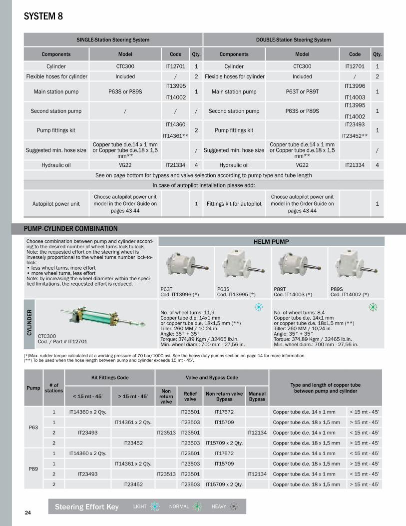
SINGLE-Station Steering System DoUBLE-Station Steering System
Components Model Code Qty. Components Model Code Qty.
Cylinder CTC300 IT12701 1 Cylinder CTC300 IT12701 1
Flexible hoses for cylinder Included / 2 Flexible hoses for cylinder Included / 2
Main station pump P63S or P89SIT13995
IT14002
1 Main station pump P63T or P89TIT13996
IT14003
1
Second station pump / / / Second station pump P63S or P89SIT13995
IT14002
1
Pump fittings kitIT14360
IT14361**
2 Pump fittings kitIT23493
IT23452**
1
Suggested min. hose sizeCopper tube d.e.14 x 1 mm or Copper tube d.e.18 x 1,5
mm**/ Suggested min. hose size
Copper tube d.e.14 x 1 mm or Copper tube d.e.18 x 1,5
mm**/
Hydraulic oil VG22 IT21334 4 Hydraulic oil VG22 IT21334 4
See on page bottom for bypass and valve selection according to pump type and tube length
In case of autopilot installation please add:
Autopilot power unitChoose autopilot power unit model in the Order Guide on
pages 43-441 Fittings kit for autopilot
Choose autopilot power unit model in the Order Guide on
pages 43-441
SyStem 8
PumP-cylinder comBination
Pump # of stations
Kit Fittings Code Valve and Bypass CodeType and length of copper tube
between pump and cylinder< 15 mt - 45’ > 15 mt - 45’
Non return valve
Relief valve
Non return valveBypass
Manual Bypass
P63
1 IT14360 x 2 Qty. IT23501 IT17672 Copper tube d.e. 14 x 1 mm < 15 mt - 45’
1 IT14361 x 2 Qty. IT23503 IT15709 Copper tube d.e. 18 x 1,5 mm > 15 mt - 45’
2 IT23493 IT23513 IT23501 IT12134 Copper tube d.e. 14 x 1 mm < 15 mt - 45’
2 IT23452 IT23503 IT15709 x 2 Qty. Copper tube d.e. 18 x 1,5 mm > 15 mt - 45’
P89
1 IT14360 x 2 Qty. IT23501 IT17672 Copper tube d.e. 14 x 1 mm < 15 mt - 45’
1 IT14361 x 2 Qty. IT23503 IT15709 Copper tube d.e. 18 x 1,5 mm > 15 mt - 45’
2 IT23493 IT23513 IT23501 IT12134 Copper tube d.e. 14 x 1 mm < 15 mt - 45’
2 IT23452 IT23503 IT15709 x 2 Qty. Copper tube d.e. 18 x 1,5 mm > 15 mt - 45’
(*)Max. rudder torque calculated at a working pressure of 70 bar/1000 psi. See the heavy duty pumps section on page 14 for more information. (**) To be used when the hose length between pump and cylinder exceeds 15 mt - 45’.
LIGHT NORMAL HEAVYSteering Effort Key
CYLI
ND
ER

25
Choose combination between pump and cylinder according to the desired number of wheel turns lock-to-lock. Note: the requested effort on the steering wheel is inversely proportional to the wheel turns number lock-to-lock:• less wheel turns, more effort• more wheel turns, less effortNote: by increasing the wheel diameter within the speci-fied limitations, the requested effort is reduced.
HELM PUMP
P63TCod. IT13996 (*)
P63SCod. IT13995 (*)
P89TCod. IT14003 (*)
P89SCod. IT14002 (*)
CTC400Cod. / Part # IT15697
No. of wheel turns: 15,9Copper tube d.e. 14x1 mmor copper tube d.e. 18x1,5 mm (**)Tiller: 350 mm / 13,78 in.Angle: 35° + 35°Torque: 400 Kgm / 34780 lb.in.Min. wheel diam.: 700 mm - 27,56 in.
No. of wheel turns: 11,2Copper tube d.e. 14x1 mmor copper tube d.e. 18x1,5 mm (**)Tiller: 350 mm / 13,78 in.Angle: 35° + 35°Torque: 400 Kgm / 34780 lb.in.Min. wheel diam.: 700 mm - 27,56 in.
CTC310Cod. / Part # IT15698
No. of wheel turns: 13,4Copper tube d.e. 14x1 mmor copper tube d.e. 18x1,5 mm (**)Tiller: 175 mm / 6,88 in.Angle: 35° + 35°Torque: 422 Kgm / 36693 lb.in.Min. wheel diam.: 700 mm - 27,56 in.
No. of wheel turns: 9,5Copper tube d.e. 14x1 mmor copper tube d.e. 18x1,5 mm (**)Tiller: 260 mm / 10,24 in.Angle: 35° + 35°Torque: 422 Kgm / 36693 lb.in.Min. wheel diam.: 700 mm - 27,56 in.
SyStem 9
Pump # of stations
Kit Fittings Code Valve and Bypass codeType and length of copper tube
between pump and cylinder< 15 mt - 45’ > 15 mt - 45’Non
return valve
Relief valveNon return
valveBypass
Manual Bypass
P63
1 IT14360 x 2 Qty. IT23501 IT17672 Copper tube d.e. 14 x 1 mm < 15 mt - 45’1 IT14361 x 2 Qty. IT23503 IT15709 Copper tube d.e. 18 x 1,5 mm > 15 mt - 45’2 IT23493 IT23513 IT23501 IT12134 Copper tube d.e. 14 x 1 mm < 15 mt - 45’2 IT23452 IT23503 IT15709 x 2 Qty. Copper tube d.e. 18 x 1,5 mm > 15 mt - 45’
P89
1 IT14360 x 2 Qty. IT23501 IT17672 Copper tube d.e. 14 x 1 mm < 15 mt - 45’1 IT14361 x 2 Qty. IT23503 IT15709 Copper tube d.e. 18 x 1,5 mm > 15 mt - 45’2 IT23493 IT23513 IT23501 IT12134 Copper tube d.e. 14 x 1 mm < 15 mt - 45’2 IT23452 IT23503 IT15709 x 2 Qty. Copper tube d.e. 18 x 1,5 mm > 15 mt - 45’
SINGLE-Station Steering System DoUBLE-Station Steering SystemComponents Model Code Qty. Components Model Code Qty.
Cylinder CTC400 or CTD310 IT15697 IT15698 1 Cylinder CTC400 or CTD310
IT15697
IT156981
Flexible hoses for cylinder Included / 2 Flexible hoses
for cylinder Included / 2
Main station pump P63S or P89S IT13995 IT14002 1 Main station pump P63T or P89T
IT13996
IT140031
Second station pump / / / Second station pump P63S or P89SIT13995
IT14002
1
Pump fittings kit IT14360 IT14361** 2 Pump fittings kit
IT23493
IT234521
Suggested min. hose size
Copper tube d.e.14 x 1 mm or Copper tube d.e.18 x 1,5 mm** / Suggested min. hose
sizeCopper tube d.e.14 x 1 mm
or Copper tube d.e.18 x 1,5 mm** /
Hydraulic oil VG22 IT21334 4 Hydraulic oil VG22 IT21334 4
See on page bottom for bypass and valve selection according to pump type and tube length
In case of autopilot installation please add:
Autopilot power unit Choose autopilot power unit model in the Order Guide on pages 43-44 1 Fittings kit for
autopilotChoose autopilot power unit model in the Order Guide on pages 43-44 1
(*) Max. rudder torque calculated at a working pressure of 70 bar/1000 psi. See the specific heavy duty pumps section on page 14 for more information. (**) To be used when the hose length between pump and cylinder exceeds 15 mt - 45’.
CYLI
ND
ER
PumP-cylinder comBination

26
Choose combination between pump and cylinder according to the desired number of wheel turns lock-to-lock. Note: the requested effort on the steering wheel is inversely proportional to the wheel turns number lock-to-lock:• less wheel turns, more effort• more wheel turns, less effortNote: by increasing the wheel diameter within the speci-fied limitations, the requested effort is reduced.
HELM PUMP
P89TCod. IT14003 (*)
P89SCod. IT14002 (*)
P105Cod. IT14052 (*)
CTD450Cod. / Part #IT15699
No. of wheel turns: 14,2Copper tube d.e. 14x1 mmor copper tube d.e. 18x1,5 mm (**)Tiller: 260 mm / 10,24 in.Angle: 35° + 35°Torque: 633 Kgm / 55040 lb.in.Min. wheel diam.: 700 mm - 27,56 in.
No. of wheel turns: 14,2Copper tube d.e. 14x1 mmor copper tube d.e. 18x1,5 mm (**)Tiller: 260 mm / 10,24 in.Angle: 35° + 35°Torque: 633 Kgm / 55040 lb.in.Min. wheel diam.: 700 mm - 27,56 in.
No. of wheel turns: 12,1Copper tube d.e. 14x1 mmor copper tube d.e. 18x1,5 mm (**)Tiller: 260 mm / 10,24 in.Angle: 35° + 35°Torque: 633 Kgm / 55040 lb.in.Min. wheel diam.: 1000 mm - 39,37 in.
SyStem 10
PumP-cylinder comBination
Pump # of stations
Kit Fittings Code Valve and Bypass CodeType and length of copper tube
between pump and cylinder< 15 mt - 45’ > 15 mt - 45’Non
return valve
Relief valve Non return valveBypass
Manual Bypass
P89
1 IT14360 x 2 Qty. IT23501 IT17672 Copper tube d.e. 14 x 1 mm < 15 mt - 45’
1 IT14361 x 2 Qty. IT23503 IT15709 Copper tube d.e. 18 x 1,5 mm > 15 mt - 45’
2 IT23493 IT23513 IT23501 IT12134 Copper tube d.e. 14 x 1 mm < 15 mt - 45’
2 IT23452 IT23503 IT15709 x 2 Qty. Copper tube d.e. 18 x 1,5 mm > 15 mt - 45’
P1051 Included IT23503 IT15709 Copper tube d.e. 18 x 1,5 mm Any length
2 IT23518 IT23503 IT15709 x 2 Qty. Copper tube d.e. 18 x 1,5 mm Any length
SINGLE-Station Steering System DoUBLE-Station Steering System
Components Model Code Qty. Components Model Code Qty.
Cylinder CTD450 IT15699 1 Cylinder CTD450 IT15699 1
Flexible hoses for cylinder Included / 2 Flexible hoses for cylinder Included / 2
Main station pump P89S or P105IT14002
IT140521 Main station pump P89T or P105
IT14003
IT140521
Second station pump / / / Second station pump P89S or P105IT14002
IT140521
Pump fittings kitIT14360
IT14361**
2 Pump fittings kit See table on page bottom 1
Suggested min. hose size
Copper tube d.e.14 x 1 mm or Copper tube d.e.18 x 1,5
mm**/ Suggested min. hose
sizeCopper tube d.e.14 x 1 mm or Copper tube d.e.18 x 1,5
mm**/
Hydraulic oil VG22 IT21334 4 Hydraulic oil VG22 IT21334 4
See on page bottom for bypass and valve selection according to pump type and tube length
In case of autopilot installation please add:
Autopilot power unit Choose autopilot power unit model in the Order Guide on pages 43-44
1 Fittings kit for autopilotChoose autopilot power unit model in the Order Guide on
pages 43-441
(*) Max. rudder torque calculated at a working pressure of 70 bar/1000 psi. See the specific heavy duty pumps section on page 14 for more information. (**) To be used when the hose length between pump and cylinder exceeds 15 mt - 45’.
LIGHT NORMAL HEAVYSteering Effort Key
CYLI
ND
ER

27
Choose combination between pump and cylinder according to the desired number of wheel turns lock-to-lock. Note: the requested effort on the steering wheel is inversely proportional to the wheel turns number lock-to-lock:• less wheel turns, more effort• more wheel turns, less effortNote: by increasing the wheel diameter within the specified limitations, the requested effort is reduced.
HELM PUMP
P89TCod. IT14003 (*)
P89SCod. IT14002 (*)
P105Cod. IT14052 (*)
P151Cod. IT14082 (*)
P191Cod. IT14084 (*)
CTE600Cod. / Part # IT15700
No. of wheel turns: 14,8Copper tube d.e. 14x1 mmor copper tube d.e. 18x1,5 mm (**)Tiller: 175 mm/6,89 in.Angle: 35° + 35°Torque: 660 Kgm/57387 lb.in.Min. wheel diam.: 700 mm - 27,56 in.
No. of wheel turns: 12,6Copper tube d.e. 14x1 mm or copper tube d.e. 18x1,5 mm (**)Tiller: 175 mm/ 6,89 in.Angle: 35° + 35°Torque: 660 Kgm/ 57387 lb.in.Min. wheel diam.: 1000 mm-39,37 in.
No. of wheel turns: 8,7Copper tube d.e. 14x1 mm or copper tube d.e. 18x1,5 mm (**)Tiller: 175 mm/ 6,89 in.Angle: 35°+35°Torque: 660 Kgm/ 57387 lb.in.Min. wheel diam.: 1000 mm-39,37 in.
No. of wheel turns: 6,9Copper tube d.e. 14x1 mm or copper tube d.e. 18x1,5 mm (**)Tiller: 175 mm/ 6,89 in.Angle: 35°+35°Torque: 660 Kgm/ 57387 lb.in.Min. wheel diam.: 1000 mm-39,37 in.
SyStem 11
Pump # of stations
Kit Fittings Code Valve and Bypass CodeType and length of copper tube
between pump and cylinder< 15 mt - 45’ > 15 mt - 45’ Non return valve Relief valve Non return valve
BypassManual Bypass
P89
1 IT14360 x 2 Qty. IT23501 IT17672 Copper tube d.e. 14 x 1 mm < 15 mt - 45’
1 IT14361 x 2 Qty. IT23503 IT15709 Copper tube d.e. 18 x 1,5 mm > 15 mt - 45’
2 IT23493 IT23513 IT23501 IT12134 Copper tube d.e. 14 x 1 mm < 15 mt - 45’
2 IT23452 IT23503 IT15709 x 2 Qty. Copper tube d.e. 18 x 1,5 mm > 15 mt - 45’
P105P151P191
1 Included IT23503 IT15709 Copper tube d.e. 18 x 1,5 mm Any length
2 IT23518 IT23503 IT15709 x 2 Qty. Copper tube d.e. 18 x 1,5 mm Any length
SINGLE-Station Steering System DoUBLE-Station Steering System
Components Model Code Qty. Components Model Code Qty.
Cylinder CTE600 IT15700 1 Cylinder CTE600 IT15700 1Flexible hoses
for cylinder Included / 2 Flexible hosesfor cylinder Included / 2
Main station pump
P89S P105 P151 P191
IT14002IT14052IT14082IT14084
1 Main station pump
P89T P105 P151 P191
IT14003IT14052IT14082IT14084
1
Second station pump / / / Second station
pump
P89S P105 P151 P191
IT14002IT14052IT14082IT14084
1
Pump fittings kitIT14360
IT14361**
2 Pump fittings kit See table on page bottom 1
Suggested min. hose size
Copper tube d.e.14 x 1 mm or Copper tube d.e.18 x 1,5 mm** / Suggested min.
hose sizeCopper tube d.e.14 x 1 mm
or Copper tube d.e.18 x 1,5 mm** /
Hydraulic oil VG22 IT21334 4 Hydraulic oil VG22 IT21334 4
See on page bottom for bypass and valve selection according to pump type and tube length
In case of autopilot installation please add:
Autopilot power unit
Choose autopilot power unit model in the Order Guide on pages 43-44
1 Fittings kit for autopilot
Choose autopilot power unit model in the Order Guide on pages 43-44 1
(*) Max. rudder torque calculated at a working pressure of 70 bar/1000 psi. See the specific heavy duty pumps section on page 14 for more information. (**) To be used when the hose length between pump and cylinder exceeds 15 mt - 45’.
CYLI
ND
ER
PumP-cylinder comBination

28
Choose combination between pump and cylinder according to the desired number of wheel turns lock-to-lock. Note: the requested effort on the steering wheel is inversely proportional to the wheel turns number lock-to-lock:• less wheel turns, more effort• more wheel turns, less effortNote: by increasing the wheel diameter within the speci-fied limitations, the requested effort is reduced.
HELM PUMP
P105Cod. IT14052 (*)
P151Cod. IT14082 (*)
P191Cod. IT14084 (*)
CTE900Cod. / Part # IT15701
No. of wheel turns: 18,8Copper tube d.e. 18x1,5 mm Tiller: 260 mm / 10,24 in.Angle: 35° + 35°Torque: 989 Kgm / 85993 lb.in.Min. wheel diam.: 1000 mm - 39,73 in.
No. of wheel turns: 13,1Copper tube d.e. 18x1,5 mm Tiller: 260 mm / 10,24 in.Angle: 35° + 35°Torque: 989 Kgm / 85993 lb.in.Min. wheel diam.: 1000 mm - 39,73 in.
No. of wheel turns: 10,4Copper tube d.e. 18x1,5 mmTiller: 260 mm / 10,24 in.Angle: 35° + 35°Torque: 989 Kgm / 85993 lb.in.Min. wheel diam.: 1000 mm - 39,73 in.
SyStem 12
PumP-cylinder comBination
Pump # of stations
Kit Fittings Code Valve and Bypass CodeType and length of copper tube
between pump and cylinder< 15 mt - 45’ > 15 mt - 45’ Non return
valveRelief valve
Non return valveBypass
Manual Bypass
P105P151P191
1 Included IT23503 IT15709 Copper tube d.e. 18 x 1,5 mm Any length
2 IT23518 IT23503 IT15709 x 2 Qty. Copper tube d.e. 18 x 1,5 mm Any length
SINGLE-Station Steering System DoUBLE-Station Steering System
Components Model Code Qty. Components Model Code Qty.
Cylinder CTE900 IT15701 1 Cylinder CTE900 IT15701 1
Flexible hoses for cylinder Included / 2 Flexible hoses
for cylinder Included / 2
Main station pump
P105 P151 P191
IT14052IT14082IT14084
1 Main station pump
P105 P151 P191
IT14052IT14082IT14084
1
Second station pump / / / Second station
pumpP105 P151 P191
IT14052IT14082IT14084
1
Pump fittings kit Included / / Pump fittings kit IT23518 1
Suggested min. hose size Copper tube d.e.18 x 1,5 mm / Suggested
min. hose size Copper tube d.e.18 x 1,5 mm /
Hydraulic oil VG22 IT21334 4 Hydraulic oil VG22 IT21334 4
See on page bottom for bypass and valve selection according to pump type and tube length
In case of autopilot installation please add:
Autopilot power unit Choose autopilot power unit model on pages 43-44 1 Fittings kit for autopilot Choose autopilot power unit
model on pages 43-44 1
(*) Max. rudder torque calculated at a working pressure of 70 bar/1000 psi. See the specific heavy duty pumps section on page 14 for more information.
LIGHT NORMAL HEAVYSteering Effort Key
CYLI
ND
ER

29
Choose combination between pump and cylinder according to the desired number of wheel turns lock-to-lock. Note: the requested effort on the steering wheel is inversely proportional to the wheel turns number lock-to-lock:• less wheel turns, more effort• more wheel turns, less effortNote: by increasing the wheel diameter within the speci-fied limitations, the requested effort is reduced.
HELM PUMP
P151Cod. IT14082 (*)
P191Cod. IT14084 (*)
CTE1200Cod. / Part # IT15702
No. of wheel turns: 17,5Copper tube d.e. 18x1,5 mm Tiller: 350 mm / 13,78 in.Angle: 35° + 35°Torque: 1318 Kgm / 114601 lb.in.Min. wheel diam.: 1000 mm - 39,37 in.
No. of wheel turns: 13,8Copper tube d.e. 18x1,5 mm Tiller: 350 mm / 13,78 in.Angle: 35° + 35°Torque: 1318 Kgm / 114601 lb.in.Min. wheel diam.: 1000 mm - 39,37 in.
SyStem 13
Pump # of stations
Kit Fittings Code Valve and Bypass CodeType and length of copper tube
between pump and cylinder< 15 mt - 45’ > 15 mt - 45’ Non return
valve Relief valveNon return
valveBypass
Manual Bypass
P151P191
1 Included IT23503 IT15709 Copper tube d.e. 18 x 1,5 mm Any length
2 IT23518 IT23503 IT15709 x 2 Qty. Copper tube d.e. 18 x 1,5 mm Any length
SINGLE-Station Steering System DoUBLE-Station Steering System
Components Model Code Qty. Components Model Code Qty.
Cylinder CTE1200 IT15702 1 Cylinder CTE1200 IT15702 1
Flexible hoses for cylinder Included / 2 Flexible hoses
for cylinder Included / 2
Main station pump
P151 P191
IT14082IT14084 1 Main station
pumpP151 P191
IT14082IT14084 1
Second station pump / / / Second station
pumpP151 P191
IT14082IT14084 1
Pump fittings kit Included / / Pump fittings kit IT23518 1
Suggested min. hose size Copper tube d.e.18 x 1,5 mm / Suggested
min. hose size Copper tube d.e.18 x 1,5 mm /
Hydraulic oil VG22 IT21334 4 Hydraulic oil VG22 IT21334 4
See on page bottom for bypass and valve selection according to pump type and tube length
In case of autopilot installation please add:
Autopilot power unit Choose autopilot power unit model on pages 43-44 1 Fittings kit for autopilot Choose autopilot power unit
model on pages 43-44 1
(*) Max. rudder torque calculated at a working pressure of 70 bar/1000 psi. See the specific heavy duty pumps section on page 14 for more information.
CYLI
ND
ER
PumP-cylinder comBination

30
Choose combination between pump and cylinder according to the desired number of wheel turns lock-to-lock. Note: the requested effort on the steering wheel is inversely proportional to the wheel turns number lock-to-lock:• less wheel turns, more effort• more wheel turns, less effortNote: by increasing the wheel diameter within the specified limitations, the requested effort is reduced.
HELM PUMP
P191Cod. IT14084 (*)
CTF1600Cod. / Part # IT15703
No. of wheel turns: 20,2Copper tube d.e. 18x1,5 mm Tiller: 350 mm / 13,78 in.Angle: 35° + 35°Torque: 1928 Kgm / 167640 lb.in.Min. wheel diam.: 1000 mm - 39,37 in.
SyStem 14
Pump # of stations
Kit Fittings Code Valve and Bypass CodeType and length of copper tube
between pump and cylinder< 15 mt - 45’ > 15 mt - 45’ Non return
valveRelief valve
Non return valveBypass
Manual Bypass
P1911 Included IT23503 IT15709 Copper tube d.e. 18 x 1,5
mm Any length
2 IT23518 IT23503 IT15709 x 2 Qty. Copper tube d.e. 18 x 1,5 mm Any length
SINGLE-Station Steering System DoUBLE-Station Steering System
Components Model Code Qty. Components Model Code Qty.
Cylinder CTF1600 IT15703 1 Cylinder CTF1600 IT15703 1
Flexible hoses for cylinder Included / 2 Flexible hoses for cylinder Included / 2
Main station pump P191 IT14084 1 Main station pump P191 IT14084 1
Second station pump / / / Second station pump P191 IT14084 1
Pump fittings kit Included / / Pump fittings kit IT23518 1
Suggested min. hose size Copper tube d.e.18 x 1,5 mm / Suggested min. hose size Copper tube d.e.18 x 1,5 mm /
Hydraulic oil VG22 IT21334 4 Hydraulic oil VG22 IT21334 4
See on page bottom for bypass and valve selection according to pump type and tube length
In case of autopilot installation please add:
Autopilot power unitChoose autopilot power unit model in the Order Guide on
pages 43-441 Fittings kit for autopilot
Choose autopilot power unit model in the Order Guide on
pages 43-441
(*) Max. rudder torque calculated at a working pressure of 70 bar/1000 psi. See the specific heavy duty pumps section on page 14 for more information.
LIGHT NORMAL HEAVYSteering Effort Key
CYLI
ND
ER
PumP-cylinder comBination

DIMENSIoNS
Model Stroke A B C D E F G H L M N P Q R S
CTA40U178 mm 555 mm 459 mm 96 mm 14 mm 19,05
mm 35 mm 86 mm 298 mm 62 mm 90 mm 40 mm 73 mm 8,5 mm 153 mm 127 mm
7.0 in. 21.85 in. 18 in. 3.78 in 0.55 in. 3/4 in. 1.38 in. 3.39 in. 11.73 in. 2.44 in. 3.54 in. 1.57 in. 2.87 in. 0.33 in. 6.0 in. 5.0 in.
CTA65U178 mm 586 mm 495 mm 91 mm 20 mm 19,05
mm 40 mm 91 mm 305 mm 60 mm 125 mm 40 mm 105 mm 8,5 mm 153 mm 127 mm
7.0 in. 23 in. 19.49 in. 3.58 in. 0.79 in. 3/4 in. 1.57 in. 3.58 in. 12.0 in. 2.36 in. 4.92 in. 1.57 in. 4.13 in. 0.33 in. 6.0 in. 5.0 in.
CTA75U200 mm 630 mm 528 mm 102 mm 20 mm 19,05
mm 40 mm 91 mm 327 mm 60 mm 125 mm 40 mm 105 mm 8,5 mm 175 mm 143 mm
7.87 in. 24.8 in. 20.79 in. 4.0 in. 0.79 in. 3/4 in. 1.57 in. 3.58 in. 12.87 in. 2.36 in. 4.92 in. 1.57 in. 4.13 in. 0.33 in. 6.89 in. 5.6 in.
CTA80U228 mm 690 mm 573 mm 117 mm 20 mm 19,05
mm 40 mm 91 mm 355 mm 60 mm 125 mm 40 mm 105 mm 8,5 mm 200 mm 164 mm
9.0 in. 27.16 in. 22.56 in. 4.61 in. 0.79 in. 3/4 in. 1.57 in. 3.58 in. 13.98 in. 2.36 in. 4.92 in. 1.57 in. 4.13 in. 0.33 in. 7.87 in. 6.5 in.
TECHNICAL DETAILS
Model Code Stroke Rudder Torque Thrust at 70 bar - 1000 psi Volume Tiller Angle Fittings Weight
CTA40U IT15649178 mm 57.83 Kgm 455 Kgf 115.7 cc 153 mm
35°+35° 1/4” NPT - 3/8” O.D.
2,2 Kg
7.0 in 5008 in/lb 1002 lbf 7.1 cu.in 6 in. 4,85 lb
CTA65U IT12677178 mm 83.81 Kgm 659.4 Kgf 167.68 cc 153 mm
35°+35° 1/4” NPT - 3/8” O.D.
2,6 Kg
7.0 in 7257 in/lb 1453 lbf 10.23 cu.in 6 in. 5,73 lb
CTA75U IT15763200 mm 94.17 Kgm 659.4 Kgf 188.4 cc 175 mm
35°+35° 1/4” NPT - 3/8” O.D.
3,0 Kg
7.78 in 8155 in/lb 1453 lbf 11.5 cu.in 6.9 in. 6,61 lb
CTA80U IT12682228 mm 107.36 Kgm 659.4 Kgf 214.78 cc 200 mm
35°+35° 1/4” NPT - 3/8” O.D.
3,2 Kg
9.0 in 9297 in/lb 1453 lbf 13.11 cu.in 7.8 in. 7,05 lb
NOTE: The inboard cylinders mod. CTA are not suitable for installations on racing boats. The cylinders mod. CTA are provided with inch fittings. Version with metric fittings are also available. Please specify when placing the order.
B C
H
F
G
A
QE
D
R
35ϒ 35ϒ
NL
P M
S
inBoard Steering cylinderS • SerieS cta
Features
• Cylinder body in anodized aluminum• Piston rod in stainless steel for a high corrosion resistance• Adjustable base either horizontally or vertically• Available in a range of volumes between 115 and 215cc• Supplied with bleeders• Meet ABYC standards
TECHNICAL SPECIFICATIONS
31

32
M
L
C
F
G
B
H
EA
35ϒ35ϒ
S
QN
R P
U
D1D
T
TECHNICAL DETAILS
Model Code Stroke Rudder Torque Thrust at 70 bar - 1000 psi Volume Tiller Angle Fittings Weight
CTB110U IT12687178 mm 140.85 Kgm 1108 Kgf 281.77 cc 153 mm
35°+35° 3/8 ” NPT - 1/2” O.D.8,6 Kg
7 in. 12197 in/lb 2442 lbf 17.19 cu.in 6 in. 18,95 lb
CTB130U IT12691204 mm 161.42 Kgm 1108 Kgf 322.93 cc 180 mm
35°+35° 3/8 ” NPT - 1/2” O.D.8,8 Kg
8 in. 13978 in/lb 2442 lbf 19.71 cu.in 7 in. 19,40 lb
CTB145U IT12694228 mm 180.41 Kgm 1108 Kgf 360.92 cc 200 mm
35°+35° 3/8 ” NPT - 1/2” O.D.9,4 Kg
9 in. 15623 in/lb 2442 lbf 22 cu.in 7.8 in. 20,72 lb
NOTE: The inboard cylinders mod. CTB are not suitable for installations on racing boats. The cylinders mod. CTB are provided with inch fittings. Version with metric fittings are also available. Please specify when placing the order.
DIMENSIoNS
Model Stroke A B C D E F G H L M N P Q R S
CTB110U178 mm 585 mm 521 mm 64 mm 22 mm 19,05 mm 57 mm 121 mm 329 mm 93 mm 112 mm 70 mm 90 mm 11 mm 153 mm 127 mm
7.0 in. 22.99 in. 20.51 in. 2.52 in. 0.87 in. 3/4 in. 2.24 in. 4.76 in. 12.95 in. 3.66 in. 4.40 in. 2.75 in. 3.54 in. 0.43 in. 6.0 in. 5.0 in.
CTB130U204 mm 622 mm 545 mm 77 mm 22 mm 16 mm 57 mm 121 mm 355 mm 93 mm 112 mm 70 mm 90 mm 11 mm 180
mm 147 mm
8.0 in. 24.45 in. 21.46 in. 3.03 in. 0.87 in. 0.63 in. 2.24 in. 4.76 in. 13.98 in. 3.66 in. 4.40 in. 2.75 in. 3.54 in. 0.43 in. 7.08 in. 5.78 in.
CTB145U228 mm 685 mm 596 mm 89 mm 22 mm 19,05 mm 57 mm 121 mm 379 mm 93 mm 112 mm 70 mm 90 mm 11 mm 200
mm 164 mm
9.0 in. 26.93 in. 23.46 in. 3.5 in. 0.87 in. 3/4 in. 2.24 in. 4.76 in. 14.92 in. 3.66 in. 4.40 in. 2.75 in. 3.54 in. 0.43 in. 7.87 in. 6.5 in.
TECHNICAL SPECIFICATIONS
inBoard Steering cylinderS • SerieS ctB
Features
• Cylinder body in brass• Piston rod in stainless steel for a high corrosion resistance• Adjustable base either horizontally or vertically• Available in a range of volumes between 281 and 360 cc• Supplied with bleeders• Meet ABYC standards

33
B C
H
FG
E
35ϒ35ϒ
R
D
P M
S
A
Q
NL
TECHNICAL DETAILS
Model Code Stroke Rudder Torque Thrust at 70 bar - 1000 psi Volume Tiller Angle Fittings Weight
CTC200 IT12695200 mm 249.93 Kgm 1750 Kgf 500 cc 175 mm
35°+35° G1/2” - d.12mm13,2 Kg
7.87 in. 21643 in/lb 3857 lbf 30.5 cu.in 6.9 in. 29,10 lb
CTC230 IT12698228 mm 284.92 Kgm 1750 Kgf 570 cc 200 mm
35°+35° G1/2” - d.12mm15,3 Kg
9 in. 24674 in/lb 3857 lbf 34.78 cu.in 7.8 in. 33,73 lb
CTC300 IT12701300 mm 374.89 Kgm 1750 Kgf 750 cc 260 mm
35°+35° G1/2” - d.12mm17,7 Kg
11.81 in. 32465 in/lb 3857 lbf 45.77 cu.in 10.2 in. 39,02 lb
CTC400 IT15697400 mm 499.85 Kgm 1750 Kgf 1000 cc 350 mm
35°+35° G1/2” - d.12mm20,0 Kg
15.75 in. 43287 in/lb 3857 lbf 61.02 cu.in 13.7 in. 44,1 lb
NOTE: The inboard cylinders mod CTC are not suitable for installations on racing boats. The cylinders mod CTC are provided with flexible hoses type SAE100 R1.
DIMENSIONS
Model Stroke A B C D E F G H L M N P Q R S
CTC200200 mm 733 mm 607 mm 127 mm 28 mm 25 mm 55 mm 133 mm 385 mm 100 mm 140 mm 72 mm 112 mm 11 mm 175 mm 143 mm
7.87 in. 28.86 in. 23.9 in. 5.0 in. 1.10 in. 0.98 in. 2.17 in. 5,25 in. 16.16 in. 3.94 in. 5.51 in. 2.83 in. 4.41 in. 0.43 in. 6.89 in. 5.6 in.
CTC230228 mm 789 mm 649 mm 141 mm 28 mm 25 mm 55 mm 133 mm 413 mm 100 mm 140 mm 72 mm 112 mm 11 mm 200 mm 164 mm
9.0 in. 31.0 in. 25.55 in. 5.55 in. 1.10 in. 0.98 in. 2.17 in. 5,25 in. 16.26 in. 3.94 in. 5.51 in. 2.83 in. 4.41 in. 0.43 in. 7.87 in. 6.5 in.
CTC300300 mm 933 mm 757 mm 177 mm 28 mm 25 mm 55 mm 133 mm 485 mm 100 mm 140 mm 72 mm 112 mm 11 mm 260 mm 215 mm
11.81 in. 36.73 in. 29.8 in. 6.97 in. 1.10 in. 0.98 in. 2.17 in. 5,25 in. 19.09 in. 3.94 in. 5.51 in. 2.83 in. 4.41 in. 0.43 in. 10.24 in. 8.5 in.
CTC400400 mm 1133 mm 907 mm 227 mm 28 mm 25 mm 55 mm 133 mm 585 mm 100 mm 140 mm 72 mm 112 mm 11 mm 350 mm 286 mm
15.75 in. 44.61 in. 35.71 in. 8.94 in. 1.10 in. 0.98 in. 2.17 in. 5,25 in. 23.0 in. 3.94 in. 5.51 in. 2.83 in. 4.41 in. 0.43 in. 13.78 in. 11.3 in.
inBoard heavy duty cylinderS• SerieS ctc
• Piston rod in stainless steel for a high corrosion resistance• Adjustable base either horizontally or vertically• Available in a range of volumes between 500 and 1000 cc• Supplied with bleeders• Meet ABYC standards
Features
TECHNICAL SPECIFICATIONS

34
C
G
F
B
A
E
35ϒ35ϒQ
D
P
L
H
N MR
TECHNICAL DETAILS
Model Code Stroke Rudder Torque Thrust at 70 bar - 1000 psi Volume Tiller Angle Thread Weight
CTD310 IT15698200 mm 421 Kgm 2954 Kgf 844 cc 175 mm
35°+35° 1/2”23 Kg
7.87 in. 36459 in/lb 6510 lbf 51,50 cu.in 6.9 in. 50,70 lb
CTD450 IT15699300 mm 633 Kgm 2954 Kgf 1266 cc 260 mm
35°+35° 1/2”25,6 Kg
11.81 in. 54818 in/lb 6510 lbf 77,25 cu.in 10.2 in. 56,43 lb
NOTE: The inboard cylinders mod CTD are not suitable for installations on racing boats. The cylinders mod CTD are provided with flexible hoses type SAE100 R1.
DIMENSIONS
Model Stroke A B C D E F G H L M N P Q R
CTD310200 mm 700 mm 633 mm 67 mm 32 mm 30 mm 90 mm 410 mm 140 mm 104 mm 170 mm 134 mm 18,5 mm 175 mm 143 mm
7.87in. 27.55 in. 24.92 in. 2.63 in. 1.25 in. 1.18 in. 3.54 in. 16.14 in. 5.51 in. 4.09 in. 25.4 in. 5.27 in. 0.72 in. 6.88 in. 5.62 in.
CTD450300 mm 900 mm 783 mm 117 mm 32 mm 30 mm 90 mm 510 mm 140 mm 104 mm 170 mm 134 mm 18,5 mm 260 mm 215 mm
11.81 in. 35.43 in. 30.82 in. 4.60 in. 1.25 in. 1.18 in. 3.54 in. 20.07 in. 5.51 in. 4.09 in. 25.4 in. 5.27 in. 0.72 in. 10.20 in. 8.44 in.
inBoard heavy duty cylinderS• SerieS ctd
TECHNICAL SPECIFICATIONS
Features
• Piston rod in stainless steel for a high corrosion resistance• Adjustable base either horizontally or vertically• Available in a range of volumes between 844 and 1266 cc• Supplied with bleeders• Meet ABYC standards

35
F
CB
G
E
35ϒ35ϒQ
D
P
L
H
NM
R
A
TECHNICAL DETAILS
Model Code Stroke Rudder Torque Thrust at70 bar - 1000 psi Volume Tiller Angle Thread Weight
CTE600 IT15700200 mm 659 Kgm 4616 Kgf 1318 cc 175 mm
35°+35° 1/2”38,5 Kg
7.87 in. 57069 in/lb 10173 lbf 21598 cu.in 6.9 in. 85 lb
CTE900 IT15701300 mm 988 Kgm 4616 Kgf 1978 cc 260 mm
35°+35° 1/2”38,8 Kg
11.81 in. 85560 in/lb 10173 lbf 32413 cu.in 10.2 in. 85,5 lb
CTE1200 IT15702400 mm 1318 Kgm 4616 Kgf 2637 cc 350 mm
35°+35° 1/2”42,0 Kg
15.75 in. 114138 in/lb 10173 lbf 43213 cu.in 13.7 in. 92,6 lb
NOTE: The inboard cylinders mod CTE are not suitable for installations on racing boats. The cylinders mod CTE are provided with flexible hoses type SAE100 R1.
DIMENSIONS
Model Stroke A B C D E F G H L M N P Q R
CTE600200 mm 735 mm 695 mm 40 mm 40 mm 35 mm 102 mm 450 mm 182 mm 143 mm 198 mm 160 mm 18,5 mm 175 mm 143 mm
7.87in. 28.93 in. 27.36 in. 1.57 in. 1.57 in. 1.37 in. 4.01 in. 17.71 in. 7.16 in. 5.62 in. 7.79 in. 6.29 in. 0.72 in. 6.88 in. 5.62 in.
CTE900300 mm 935 mm 845 mm 90 mm 40 mm 35 mm 102 mm 555 mm 182 mm 143 mm 198 mm 160 mm 18,5 mm 260 mm 215 mm
11.81 in. 36.81 in. 33.26 in. 3.54 in. 1.57 in. 1.37 in. 4.01 in. 21.85 in. 7.16 in. 5.62 in. 7.79 in. 6.29 in. 0.72 in. 10.20 in. 8.44 in.
CTE1200400 mm 1135 mm 995 mm 140 mm 40 mm 35 mm 102 mm 650 mm 182 mm 143 mm 198 mm 160 mm 18,5 mm 350 mm 286 mm
15.75 in. 44.68 in. 37.59 in. 5.51 in. 1.57 in. 1.37 in. 4.01 in. 25.59 in. 7.16 in. 5.62 in. 7.79 in. 6.29 in. 0.72 in. 13.77 in. 11.25 in.
inBoard heavy duty cylinderS• SerieS cte
Features
• Piston rod in stainless steel for a high corrosion resistance• Adjustable base either horizontally or vertically• Available in a range of volumes between 844 and 1266 cc• Supplied with bleeders• Meet ABYC standards
TECHNICAL SPECIFICATIONS

36
B
G
C
F
E
35ϒ35ϒ
Q
D
AP
L H
NM
R
TECHNICAL DETAILS
Model Code Stroke Rudder Torque Thrust at 70 bar - 1000 psi Volume Tiller Angle Thread Weight
CTF1600 IT15703400 mm 1928 Kgm 6750 Kgf 3857 cc 350 mm
35°+35° 1/2”78,8 Kg
15.75 in. 166964 in/lb 14850 lbf 235,27 cu.in 13,77 in. 173,72 lb
NOTE: The inboard cylinders mod CTF are not suitable for installations on racing boats. The cylinders mod CTF are provided with flexible hoses type SAE100 R1.
DIMENSIoNS
Model Stroke A B C D E F G H L M N P Q R
CTF1600400 mm 1205 mm 935 mm 270 mm 46 mm 36 mm 130 mm 580 mm 240 mm 190 mm 300 mm 250 mm 20,5 mm 350 mm 286 mm
15.75 in. 47.44 in. 36.81 in. 10.62 in. 1.81 in. 1.41 in. 5.11 in. 22.83 in. 9.44 in. 7.48 in. 11.81 in. 9.84 in. 0.80 in. 13.77 in. 11.25 in.
inBoard heavy duty cylinderS• SerieS ctf
TECHNICAL SPECIFICATIONS
Features
• Piston rod in stainless steel for a high corrosion resistance• Adjustable base either horizontally or vertically• Available in a range of volumes between 844 and 1266 cc• Supplied with bleeders• Meet ABYC standards

37
manual inBoard Steering SyStemS order guide aPPlication guide according to Boat length and tyPe
WARNING! The above suggestions shall be intended as merely INDICATIVE. To check the proper application the required max torque must be calculated. If the required information is not available please contact our authorized dealer or service center and submit boat length, maximum speed and rudder dimensions.
WARNING! For displacement boats, hull speed normally does not exceed 18 knots. For planing boats, the above steering systems are suggested for boat speeds under 30 knots.
Boat lengthLoA
System to order
Planing Hull Displacement Hull
1 Engine 2 Engines 1 Engine 2 Engines
Pleasure Working Pleasure Working Pleasure Working Pleasure Working
Up to 8mt / 26ft 1 2 1 2 1 2 1 2
8 - 9,8mt / 26 - 32ft 1 2 1 2 2 3 2 3
9,8 - 11,6mt / 32 - 38ft 2 3 2 3 3 4 2 3
11,6 - 13,4mt / 38 - 44ft 3 4 2 4 4 6 3 5
13,4 - 15,3mt / 44 - 50ft 7 7 4 5 6 7 5 6
15,5 - 16,8mt / 50 - 55ft 8 9 5 6 7 8 7 8
16,8 - 18mt / 55 - 60ft 8 9 6 7 8 8 8 8
18 - 19,8mt / 60 - 65ft / / 8 / 8 9 8 9
19,8 - 21mt / 65 - 70ft / / 8 / 9 9 9 10
21 - 22,8mt / 70 - 75ft / / 9 / 10 11 10 11
22,8 - 24,3mt / 75- 80ft / / 9 / 10 11 10 11
over 24,3 mt / 80ft For boat lengths over 24,3 mt / 80 ft please contact our technical department to check applications suggested on systems 12-14
CYLINDERSystem to order
Mod. CodeCTA40U - CTA40 IT15649 - IT12675 System 1 (see pg. 17)
CTA65U - CTA65CTA75U - CTA75
IT12677 - IT12676 IT15763 - IT12678 System 2 (see pg. 18)
CTA80U - CTA80 IT12682 - IT12679 System 3 (see pg. 19)
CTB110U - CTB110 CTB130U - CTB130
IT12687 - IT12683 IT12691 - IT15606 System 4 (see pg. 20)
CTB145U - CTB145 IT12694 - IT12692 System 5 (see pg. 21)
CTC200 IT12695 System 6 (see pg. 22)
CTC230 IT12698 System 7 (see pg. 23)
CTC300 IT12701 System 8 (see pg. 24)
CTC400 CTD310
IT15697 IT15698 System 9 (see pg. 25)
CTD450 IT15699 System 10 (see pg. 26)
CTE600 IT15700 System 11 (see pg. 27)
CTE900 IT15701 System 12 (see pg. 28)
CTE1200 IT15702 System 13 (see pg. 29)
CTF1600 IT15703 System 14 (see pg. 30)

38
AUToPILoT PoWER UNITS
The autopilot and other electronic navigation systems are more popular today on every type of vessel, even smaller ones. Since these modern technologies are more and more sophisticated it is necessary for the equipment to be able to exchange information and work together to guarantee safe navigation.
Twin Disc has developed a complete range of autopilot power units that represent the best interface for your autopilot.
Through thirty years of experience and research, we have learned the autopilot power unit range can provide simple solutions in terms of working principle and installation, while providing reliable and precise performance.
It is possible to choose among several types of units:
- SOLENOID - VALVE POWER UNITS- SOLENOID - VALVE POWER UNITS WITH AUTOMATIC FILLING- REVERSIBLE POWER UNITS
Each one of the types above is fully described in a dedicated section in this catalogue. Please check the different tables for the products characteristics and technical details. For the choice of the most suitable unit it is necessary to have the steering cylinder volume, from which the actuation time is calculated and the suitable model selected.
Features
• Reduced dimensions • Great variety of models for any kind of application • Availability of reversible and solenoid-valve Power Units• Steering automatic filling device available on certain
models for an easier and faster bleeding• Interface with any autopilot• High quality materials and components for the best
reliability and performance

39
autoPilot Solenoid-valve Power unitS with automatic filling device• mod. c03rau - c04rau
• Available in two models for application with steering cylinders having a volume up to 500 cc
• Safe and precise interface with any autopilot• Very compact design and reduced dimensions• Supplied with solenoid-valves electro-magnetically
actuated• Special device for the steering automatic filling• Easy and fast steering bleeding
Features
This is a special innovative version of the autopilot power unit with solenoid valves. This model has all the main features of the range which supply a safe and precise interface for the autopilot, but also is equipped with a special device that allows the automatic filling of the steering system.
The installation and working principle of these units are exactly the same as traditional units, but this additional device circulates oil automatically in the steering hoses as soon as the unit is switched on, allowing any air remaining in the system to go out through the designed bleeders.
In this way, the troublesome bleeding procedure becomes much easier and quicker (and nearly automatic) if the unit has not been used for some time. The steering wheel is turned occasionally from port to starboard and vice-versa.
The unit composition and its main features are exactly the same as for the normal solenoid-valve power units described in the previous section.
DIMENSIoNS
Model A B C
CO3RAUCO3RA
370 mm 230 mm 240 mm
14,56 in. 9 in. 9,44 in.
CO4RAUCO4RA
370 mm 230 mm 380 mm
14,56 in. 9 in. 14,96 in.
TECHNICAL SPECIFICATIONS AND APPLICATIONS

40
Features
DIMENSIoNS
Model A B C
CO1NUCO1N
160 mm 185 mm 285 mm
6,30 in. 7,28 in. 11,22 in.
CO2NUCO2N
160 mm 185 mm 285 mm
6,30 in. 7,28 in. 11,22 in.
CO2/3NUCO2/3N
185 mm 185 mm 360 mm
7,28 in. 7,28 in. 14,17 in.
CO3NUCO3N
185 mm 185 mm 360 mm
7,28 in. 7,28 in. 14,17 in.
Autopilot power units with solenoid valves include several models with different characteristics and displacements to satisfy a wide application field on any type of boat. The system’s major components are an electric motor, a hydraulic pump, an oil tank and an electromagnetically actuated valve group.
The unit dimensions allow installation in small, narrow areas, and the installation is very easy and fast. To select the most suitable model, first verify the steering cylinder volume and then select the suggested model on our Order Guide on pages 43-44. For any special application, please contact a specialized installer or dealer for help in the product selection.
autoPilot Power unitS with Solenoid-valveS• mod. c01nu - c03nu
TECHNICAL SPECIFICATIONS
• Wide range of models with different displacements to satisfy any application
• Safe and precise interface with any autopilot• Compact design • Supplied with electro-magnetically actuated
solenoid valves
A
B
C

41
DIMENSIoNS
Model A B C
CO7230 mm 230 mm 270 mm
9,06 in. 9,06 in. 10,63 in.
CO8230 mm 230 mm 270 mm
9,06 in. 9,06 in. 10,63 in.
CO9240 mm 310 mm 350 mm
9,45 in. 12,20 in. 13,78 in.
CO10230 mm 230 mm 270 mm
9,06 in. 9,06 in. 10,63 in.
CO11240 mm 310 mm 350 mm
9,45 in. 12,20 in. 13,78 in.
CO12240 mm 310 mm 350 mm
9,45 in. 12,20 in. 13,78 in.
CO13240 mm 360 mm 350 mm
9,45 in. 14,17 in. 13,78 in.
CO14300 mm 360 mm 350 mm
11,81 in. 14,17 in. 13,78 in.
CO15300 mm 360 mm 350 mm
11,81 in. 14,17 in. 13,78 in.
CO16300 mm 360 mm 350 mm11,81 in. 14,17 in. 13,78 in.
autoPilot Power unitS with Solenoid-valveS• mod. c04 - c04/5
DIMENSIoNS
Model A B C
CO4270 mm 200 mm 310 mm
10,63 in. 7.8 in. 12,20 in.
CO4/5270 mm 200 mm 310 mm
10,63 in. 7.8 in. 12,20 in.
TECHNICAL SPECIFICATIONS
autoPilot Power unitS with Solenoid-valveS• Mod. C07 - C016
C
A
B
C
AB
TECHNICAL SPECIFICATIONS

42
A
B
C
DIMENSIoNS
Model A B CCO1RU - CO1R 160 mm / 6,30 in. 155 mm / 6,10 in. 285 mm / 11,22 in.
CO2RU - CO2R 160 mm / 6,30 in. 155 mm / 6,10 in. 285 mm / 11,22 in.
CO3RU - CO3R 185 mm / 7,28 in. 155 mm / 6,10 in. 360 mm / 14,17 in.
CO4NRU - CO4NR 185 mm / 7,28 in. 155 mm / 6,10 in. 360 mm / 14,17 in.
Four different models of reversible power units are available for autopilot application with steering cylinders having a volume up to 500cc. They have the same performances as the solenoid-valve units, ensuring a precise and reliable interface with the autopilot software, but with a lower electrical consumption. These are suggested for all applications where the power consumption is critical, and must be as low as possible.
The unit is composed basically of a reversible electric motor, a reversible hydraulic pump, an oil tank and a filter group. Their dimensions have been reduced, allowing installation in very narrow places.
For the selection of the optimum system, please determine the steering cylinder volume and then choose the suggested model in our Order Guide on the following page.
TECHNICAL SPECIFICATIONS AND APPLICATIONS
reverSiBle autoPilot Power unitS• mod. c01r - c04r
• Available in four models for steering cylinder volumes up to 500 cc• Precise and reliable interface with the autopilot• Compact design and reduced dimensions• Very low electric consumption
Features

43
(*) Weight is intended without oil.
CO3RAU 12VCO3RA 12V
CO3RAU 24VCO3RA 24V
IT23338IT18044IT12552IT12551
130-360 ccCTA65UCTA65
CTA75UCTA75
CTA80UCTA80
CTB110UCTB110
12,2 13,815,820,7
816 cc/min. 50 bar 11 A 16 A
125 W
7 lt 10 Kg-20,04 lb
7,93-21,96 cu.in.
49,77 cu.in. 725 psi 6 A 10 A 427
in.cu10,5 Kg-23,14 lb
CO4RAU 12V CO4RAU 12V CO4RA 24V
IT23339 IT12569IT12568
360-500 ccCTB130UCTB130
CTB145UCTB145CTC200CTC300
1011,215,423,2
1940 cc/min. 50 bar 26 A 32 A
150 W
12 lt 15 Kg-33,06 lb
21,96-30,5 cu.in.
118,34 cu.in 725 psi 13 A 16 A 732
in.cu15,5 Kg-34,16 lb
ORDER GUIDE AND TECHNICAL DETAILS
Model Code Typical cylinder
application
Cylinderapplication
Application time in sec.
Displace-ment
Settingpressure
Max power consumption
Therm protection
Motor nominal power
Tank capacity Weight*
CO1RU 12VCO1R 12V
CO1RU 24VCO1R 24V
IT21305IT12519
IT21306IT11341
70 - 100 cc
/depending on the cylinder
volume
360 cc/min 50 bar 7 A 10 A
80 W
0.55 lt 6.5 Kg
4.27 - 6.1 cu.in
21.97 cu.in 725 psi 4.5 A 10 A 33,56
in.cu 14,33 lb
CO2RU 12VCO2R 12V
CO2RU 24VCO2R 24V
IT21307IT12535
IT21308IT12536
115 - 130 cc
CTA40U - CTA40 14,5
480 cc/min 50 bar 8,5 A 10 A
80 W
0.55 lt 6.5 Kg
6.1 - 7.93 cu.in
29.30 cu.in 725 psi 4,5 A 10 A 33,56
in.cu 14,33 lb
CO3RU 12VCO3R 12V
CO3RU 24VCO3R 24V
IT21309 IT15710IT21310IT12550
130 - 360 cc CTA40U - CTA40CTA75U - CTA75CTA80U - CTA80
CTB110U - CTB110CTB130U - CTB130CTB145U - CTB145
10,511,713,417,6
20,1822,5
960 cc/min 50 bar 10 A 16 A
125 W
0.95 lt 8.5 Kg
7.93 - 13.42 cu.in
58.56 cu.in 725 psi 7 A 10 A 33,56
in.cu 18,73 lb
CO4NRU 12VCO4NR 12V
CO4NRU 24VCO4NR 24V
IT21311 IT15711IT21312IT15712
360 - 500 cc
CTC200CT230
15,617,8
1920 cc/min 50 bar 22 A 25 A
150 W
0.95 lt 8.5 Kg
21.96 - 30,5 cu.in
117.12 cu.in 725 psi 11 A 16 A 33,56
in.cu 18,73 lb
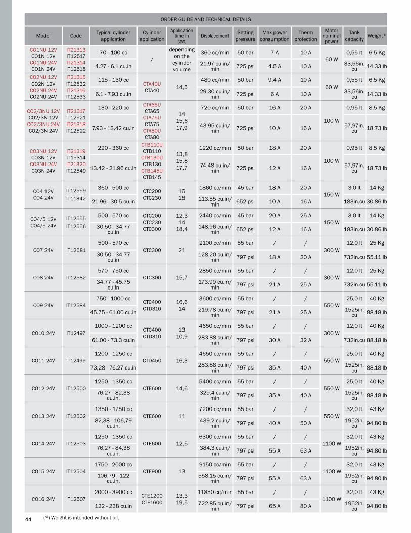
ORDER GUIDE AND TECHNICAL DETAILS
Model Code Typical cylinder application
Cylinder application
Application time in
sec.Displacement Setting
pressure Max power
consumptionTherm
protection
Motor nominal power
Tank capacity Weight*
CO1NU 12VCO1N 12V
CO1NU 24VCO1N 24V
IT21313IT12517IT21314 IT12518
70 - 100 cc/
depending on the
cylinder volume
360 cc/min 50 bar 7 A 10 A60 W
0,55 lt 6.5 Kg
4.27 - 6.1 cu.in 21.97 cu.in/min 725 psi 4.5 A 10 A 33,56in.
cu 14.33 lb
CO2NU 12VCO2N 12V
CO2NU 24VCO2NU 24V
IT21315IT12532 IT21316IT12533
115 - 130 ccCTA40U CTA40 14,5
480 cc/min 50 bar 9.4 A 10 A60 W
0,55 lt 6.5 Kg
6.1 - 7.93 cu.in 29.30 cu.in/min 725 psi 6 A 10 A 33,56in.
cu 14.33 lb
CO2/3NU 12VCO2/3N 12V
CO2/3NU 24VCO2/3N 24V
IT21317IT12521 IT21318IT12522
130 - 220 cc CTA65UCTA65
CTA75UCTA75
CTA80U CTA80
1415,617,9
720 cc/min 50 bar 16 A 20 A
100 W
0,95 lt 8.5 Kg
7.93 - 13.42 cu.in 43.95 cu.in/min 725 psi 10 A 16 A 57,97in.
cu 18.73 lb
CO3NU 12VCO3N 12V
CO3NU 24V CO3N 24V
IT21319IT15314 IT21320IT12549
220 - 360 cc CTB110UCTB110
CTB130UCTB130
CTB145UCTB145
13,815,817,7
1220 cc/min 50 bar 18 A 20 A
100 W
0,95 lt 8.5 Kg
13.42 - 21.96 cu.in 74.48 cu.in/min 725 psi 12 A 16 A 57,97in.
cu 18.73 lb
CO4 12V CO4 24V
IT12559IT11342
360 - 500 ccCTC200 CTC230
1618
1860 cc/min 45 bar 18 A 20 A150 W
3,0 lt 14 Kg
21.96 - 30.5 cu.in 113.55 cu.in/min 652 psi 10 A 16 A 183in.cu 30.86 lb
CO4/5 12V CO4/5 24V
IT12555IT12556
500 - 570 cc CTC200CTC230 CTC300
12,314
18,4
2440 cc/min 45 bar 20 A 25 A150 W
3,0 lt 14 Kg
30.50 - 34.77 cu.in
148.96 cu.in/min 652 psi 12 A 16 A 183in.cu 30.86 lb
CO7 24V IT12581500 - 570 cc
CTC300 212100 cc/min 55 bar / /
300 W12,0 lt 25 Kg
30.50 - 34.77 cu.in
128.20 cu.in/min 797 psi 18 A 20 A 732in.cu 55.11 lb
CO8 24V IT12582570 - 750 cc
CTC300 15,72850 cc/min 55 bar / /
300 W12,0 lt 25 Kg
34.77 - 45.75 cu.in
173.99 cu.in/min 797 psi 21 A 25 A 732in.cu 55.11 lb
CO9 24V IT12584750 - 1000 cc
CTC400CTD310
16,614
3600 cc/min 55 bar / /550 W
25,0 lt 40 Kg
45.75 - 61.00 cu.in 219.78 cu.in/min 797 psi 21 A 25 A 1525in.
cu 88.18 lb
CO10 24V IT124971000 - 1200 cc
CTC400CTD310
1310,9
4650 cc/min 55 bar / /300 W
12,0 lt 40 Kg
61.00 - 73.3 cu.in 283.88 cu.in/min 797 psi 30 A 32 A 732in.cu 88.18 lb
CO11 24V IT124991200 - 1250 cc
CTD450 16,34650 cc/min 55 bar / /
550 W25,0 lt 40 Kg
73,28 - 76,27 cu.in 283.88 cu.in/min 797 psi 35 A 40 A 1525in.
cu 88.18 lb
CO12 24V IT125001250 - 1350 cc
CTE600 14,65400 cc/min 55 bar / /
550 W25,0 lt 40 Kg
76,27 - 82,38 cu.in.
329.4 cu.in/min 797 psi 35 A 40 A 1525in.
cu 88,18 lb
CO13 24V IT125021350 - 1750 cc
CTE600 117200 cc/min 55 bar / /
550 W32,0 lt 43 Kg
82,38 - 106,79 cu.in.
439.2 cu.in/min 797 psi 40 A 50 A 1952in.
cu 94,80 lb
CO14 24V IT125031250 - 1350 cc
CTE600 12,56300 cc/min 55 bar / /
1100 W32,0 lt 43 Kg
76,27 - 84,38 cu.in.
384.3 cu.in/min 797 psi 55 A 63 A 1952in.
cu 94,80 lb
CO15 24V IT125041750 - 2000 cc
CTE900 139150 cc/min 55 bar / /
1100 W32,0 lt 43 Kg
106,79 - 122 cu.in.
558.15 cu.in/min 797 psi 55 A 63 A 1952in.
cu 94,80 lb
CO16 24V IT125072000 - 3900 cc CTE1200
CTF160013,319,5
11850 cc/min 55 bar / /1100 W
32,0 lt 43 Kg
122 - 238 cu.in 722.85 cu.in/min 797 psi 65 A 80 A 1952in.
cu 94,80 lb
(*) Weight is intended without oil.44

45
The Twin Disc Power Assisted Steering system is the combination of innovation, reliability and comfort. The system provides prompt responsivity and total control with just 3.5 wheel turns lock-to-lock, even at high speeds (over 28 Knots). The compact design and reduced number of components (3 vs 6-7 in other brands) allows the system to be easy to install and service.
Twin Disc power-assisted steering assures maximum comfort, minimum effort, total efficiency in any sea condition.
The SystemThe hydraulic helm pump is available in all displacements and mounting configurations (see help pump on page 9 for the model selection). Simple design with reduced dimensions for the steering cylinder, which are available either in anodized aluminum body (for applications up to 45’), or in a brass body for heavier applications, has the servo cylinder mounted directly to the main cylinder.
The Twin Disc power-assisted steering is completely independent from the vessel’s main engines and all necessary power is provided by a single electrohydraulic power unit.
The system has all the necessary valves for the servo system in order to ensure safe steering (non-return valves, relief valves, etc.). It also includes an interface for the autopilot and a special device for the system automatic filling.
In order to ensure safety and total boat control in emergency conditions, the Twin Disc steering system automatically turns into a manual system if there is any problem with the unit.
Features
• Totally independent from the vessel propulsion system• Effortless navigation comfort in any condition • High quality, safety and reliability• Innovative concept and working principle• 3 elements of the basic system vs. 6-7 elements in other brands• Strong reduction of installation time (over 30% in comparison with competitors steering)• Prompt responsiveness and total control in just 3.5 turns lock-to-lock (this number can be varied)• Cooling system is not necessary• Supplied with interface for the autopilot• Special device for automatic filling of the system• Bleeding procedure easy and fast• Steering helm pump available in 5 displacements and 4 mounting configurations• Provided with automatic manual back-up steering• Simplified service and repair procedures (the system is not pressurized)• Limited number of spare parts• Helm pumps and cylinders meet ABYC standards and are approved• Helm pumps are NMMA Type Approved
Power-aSSiSted inBoard Steering SyStemS

46
Main Features
• Compact design with reduced dimensions • Servo cylinder integrally fixed to the main one• Available in a wide variety of volumes and strokes for application flexibility• Provided with bleeders• Available with anodized aluminum or bronze body• Piston rod in stainless steel• Cylinder base twisting either horizontally or vertically• High resistance to corrosion• Meet ABYC standards • marked
WoRKING PRINCIPLE
The power-assisted steering cylinders are available with anodized aluminum body (for applications up to 45’), or with a brass body (for applications over 45’).
The small servo cylinder is mounted directly to the main cylinder. This results in an extremely simple design with reduced dimensions for an easy installation in very narrow spaces.
The piston rod is made of stainless steel for both the servo and main cylinders allowing longer life and higher resistance to rust and corrosion.
The standard dimensions of ball joints can be easily ordered and can be supplied in stainless steel upon request.
The cylinder base can be adjusted either horizontally, to follow the complete arc of the cylinder, or vertically, in order to adapt to any tiller extension.
Every cylinder is supplied with Tee fittings with bleeders as well as the necessary fittings for hose connection.
All cylinders are built with materials suitable for application in the marine environment, where there is a high level of salinity.
In case of particularly difficult environmental conditions, stainless steel ball joints and fittings are recommended.
CyLINDERS
The power-assisted steering is totally independent; the electro-hydraulic power unit provides all the necessary power.
The steering system consists of an axial piston helm pump and a power assisted cylinder, which has the servo cylinder mounted on its body.
1. By turning the steering wheel, an oil flow is sent from the helm pump to the small servo cylinder mounted on the main one.
2. This flow enters the cylinder and makes the piston move. The pressure resulting from this movement is used to open a distributor placed on the electro-hydraulic power unit.
3. As the distributor opens, an oil flow reaches the main cylinder moving the piston as well as the rod connected to the tiller arm. This causes the rudder to rotate.
4. Oil displaced from the opposite side of the main cylinder flows back to the helm pump.
5. To rotate the rudder in the opposite direction, simply turn the helm pump the other way.
In case of electrical failure (i.e. the power unit cannot be turned on or is out of order), by turning the helm pump oil flows automatically into the main cylinder which then allows the rudder to rotate.
The power-assisted steering automatically becomes a manual hydraulic back-up system with no need for switching anything or open/close any bypass.

47
GLF
M
CB
H
A
DD1
E
35ϒ 35ϒT
SQ
N
R PU
TECHNICAL DETAILS
Model Code Stroke Rudder Torque Thrust at 70 bar - 1000 psi Volume Tiller Angle Fittings Weight
CTA80AUCTA80A
IT12681IT12680
228 mm 107.33 Kgm 659,4 Kgf 214.78 cc 200 mm35° + 35° 1/4”NPT -
3/8” O.D.5,5 Kg
9.0 in 9297 in/lb 1453 lbf 13.11 cu.in 7,8 in. 12,13 lb
NOTE: The power-assisted inboard steering cylinders type CTA_A are not suitable for installations on racing boats.
DIMENSIoNS
Model Stroke A B C D D1 E F G H L M N P Q R S T U
CTA80AUCTA80A
228 mm
741 mm
578mm
162mm
20mm
14 mm
19,05 mm
40mm
130mm
360mm
45mm
120mm
60mm
125 mm
40mm
105mm
8,5mm
200mm
165 mm
9,0 in.
29,17 in.
22,77 in.
6,38 in.
0,79 in.
0,55 in.
3/4 in.
1,57 in.
5,11 in.
13,17 in.
1,77 in.
4,72 in.
2,36in.
4,92in.
1,57 in.
4,13in.
0.33 in.
7,87in.
6,5in.
Power-aSSiSted inBoard Steering cylinderS • SerieS cta_au
TECHNICAL SPECIFICATIONS
Power-assisted steering cylinders are available either with an anodized aluminum body (for applications up to 45’), or with a brass body, for applications over 45’.The small servo-cylinder is mounted directly to the main cylinder. This results in an extremely simple design with reduced dimensions for easy installation in very narrow spaces.
The piston rod is made of stainless steel in both servo and main cylinders for longer life and a higher resistance to rust and corrosion. Ball joints are available in the most popular sizes for the market and can be supplied in stainless steel upon request. The cylinder base can adjust either horizontally, to follow the complete arc of the cylinder, or vertically, in order to adapt to any tiller extension.
Every cylinder is supplied with Tee fittings with bleeders as well as the necessary fittings for hose connection.All cylinders are built with materials suitable for application in marine environment, even high salt conditions.In case of difficult environment conditions, it is suggested to request the stainless steel versions of ball joint and fittings.
Main Features
• Cylinder body in anodized aluminum• Piston rod in stainless steel for a high corrosion
resistance• Adjustable base either horizontally or vertically• Supplied with bleeders• Meets ABYC standards

48
B C
H
F
G
M
L
E
35ϒ35ϒT
DD1
A
S
R P
UQN
DIMENSIoNS
Model Stroke A B C D D1 E F G H L M N P Q R S T U
CTB110AUCTB110A
178 mm
666 mm
521 mm
146 mm 22 mm 14 mm 19,05
mm 57mm
116mm
329mm
58mm
140mm
93mm
112mm
70mm
90mm
11mm
153mm
127 mm
7.0 in.
26,22 in.
20,51 in.
5.75 in.
0.87 in.
0.55 in.
3/4 in.
2.24 in.
4.56 in.
12.95 in.
2.28 in.
5.51 in.
3.66 in.
4.4 in.
2.75 in.
3.54 in.
0.43 in.
6.0 in.
5,0 in.
CTB130AUCTB130A
204 mm
703 mm
545mm
159mm
22mm
14 mm
16mm
57mm
116mm
355mm
58mm
140mm
93mm
112mm
70mm
90mm
11mm
180mm
147 mm
8.0 in.
27,68 in.
21.46 in.
6,26 in.
0.87 in.
0.55 in.
0,63 in.
2.24 in.
4.56 in.
13.98 in.
2.28 in.
5.51 in.
3.66 in.
4.4 in.
2.75 in.
3.54 in.
0.43 in.
7.08 in.
5,78 in.
CTB145AUCTB145A
228 mm
766 mm
596mm
171mm
22mm
14 mm
19,05mm
57mm
116mm
379mm
58mm
140mm
93mm
112mm
70mm
90mm
11mm
200mm
164 mm
9.0 in.
30,16 in.
23.46 in.
6.73 in.
0.87 in.
0.55 in.
3/4 in.
2.24 in.
4.56 in.
14.92 in.
2.28 in.
5.51 in.
3.66 in.
4.4 in.
2.75 in.
3.54 in.
0.43 in.
7.87 in.
6,5 in.
TECHNICAL DETAILS
Model Code Stroke Rudder Torque Thrust at 70 bar - 1000 psi Volume Tiller Angle Fittings Weight
CTB110AUCTB110A
IT12686IT12684
178 mm 140.85 Kgm 1108 Kgf 281,77 cc 153 mm35°+35° 1/4”NPT - 3/8” O.D.
11,9 Kg
7.0 in. 12197 in/lb 2442 lbf 17.19 cu.in 6.0 in. 26,2 lb
CTB130AUCTB130A
IT12690IT12688
204 mm 161,42 Kgm 1108 Kgf 322,93 cc 180 mm35°+35° 1/4”NPT - 3/8” O.D.
12,3 Kg
8.0 in. 13978 in/lb 2442 lbf 19,71 cu.in 7.0 in. 27,2 lb
CTB145AUCTB145A
IT15883IT12693
228 mm 180.41 Kgm 1108 Kgf 360,92 cc 200 mm35°+35° 1/4”NPT - 3/8” O.D.
13,1 Kg
9.0 in. 15623 in/lb 2442 lbf 22,0 cu.in 7.87 in. 28,85 lb
NOTE: The power-assisted inboard steering cylinders type CTB_A are not suitable for installations on racing boats.
Power-aSSiSted inBoard Steering cylinderS• SerieS ctB_au
Features
• Cylinder body in brass• Piston rod in stainless steel for a high corrosion
resistance• Adjustable base either horizontally or vertically• Available in a range of volumes between 280 cc
and 360 cc• Supplied with bleeders• Meets ABYC standards
TECHNICAL SPECIFICATIONS

49
M
L
C
F
G
B
H
EA
35ϒ35ϒ
S
QN
R P
U
D1D
T
TECHNICAL DETAILS
Model Code Stroke Rudder Torque Thrust at 70 bar - 1000 psi Volume Tiller Angle Fittings Weight
CTC200AUCTC200A
IT15885IT12696
200 mm 249,93 Kgm 1750 Kgf 500,0 cc 175 mm35°
+35°1/4”NPTF - 3/8” D.E. for Servo-control cylinder1/4”NPTF - 1/2” D.E. for main cylinderG1/4 - hose d. 10 e T - G1/2 - hose d.10
16,8 Kg
7,87 in. 21643 in/lb 3857 lbf 30.5 cu.in 6.9 in. 37,1 lb
CTC230AUCTC230A
IT15887IT12699
228 mm 284,92 Kgm 1750 Kgf 570,0 cc 200 mm35°
+35°1/4”NPTF - 3/8” D.E. for Servo-control cylinder1/4”NPTF - 1/2” D.E. for main cylinderG1/4 - hose d. 10 e T - G1/2 - hose d.10
19,2 Kg
9.0 in. 24674 in/lb 3857 lbf 34,78 cu.in 7.87 in. 42,3 lb
CTC300AUCTC300A
IT15889IT15715
300 mm 374.89 Kgm 1750 Kgf 750,0 cc 260 mm35°
+35°1/4”NPTF - 3/8” D.E. for Servo-control cylinder1/4”NPTF - 1/2” D.E. for main cylinderG1/4 - hose d. 10 e T - G1/2 - hose d.10
21,8 Kg
11.81 in. 32465 in/lb 3857 lbf 45.77 cu.in 10.2 in. 48,1 lb.
CTC400AUCTC400A
IT16136IT12702
400 mm 499.85 Kgm 1750 Kgf 1000,0 cc 350 mm35°
+35°1/4”NPTF - 3/8” D.E. for Servo-control cylinder1/4”NPTF - 1/2” D.E. for main cylinderG1/4 - hose d. 10 e T - G1/2 - hose d.10
26,8 Kg
15.75 in. 43287 in/lb 3857 lbf 61,02 cu.in 13.7 in. 59 lb
NOTE: The cylinders type CTC_A are not suitable for installations on racing boats.
DIMENSIoNS
Model Stroke A B C D D1 E F G H L M N P Q R S T U
CTC200AUCTC200A
200 mm
767mm
607mm
161mm
28 mm
14 mm
25 mm
55 mm
132,5mm
385mm
65 mm
162mm
100mm
140mm
72mm
112 mm
11 mm
175mm
143mm
7.87 in.
30.2in.
23.9in.
6.34in.
1,10in.
0,55in.
0,98in.
2,17in.
5,22in.
15,16in.
2,56in.
6,38in.
3,94in.
5,51in.
2,83in.
4,41in.
0,43in.
6,89in.
5,6in.
CTC230AUCTC230A
228 mm
823mm
649mm
175mm
28 mm
14 mm
25mm
55mm
132,5mm
413mm
65mm
162mm
100mm
140mm
72mm
112mm
11mm
200mm
164mm
9.0 in.
32.4in.
25.55in.
6.89in.
1,10in.
0,55in.
0,98in.
2,17in.
5,22in.
16,26in.
2,56in.
6,38in.
3,94in.
5,51in.
2,83in.
4,41in.
0,43in.
7,87in.
6,5in.
CTC300AUCTC300A
300 mm
967mm
757mm
211mm
28mm
14mm
25mm
55mm
132,5mm
485mm
65mm
162mm
100mm
140mm
72mm
112mm
11mm
260mm
215mm
11,81 in.
38in.
29.8in.
8.3in.
1,10in.
0,55in.
0,98in.
2,17in.
5,22in.
19,09in.
2,56in.
6,38in.
3,94in.
5,51in.
2,83in.
4,41in.
0,43in.
10,24in.
8,5in.
CTC400AUCTC400A
400 mm
1167mm
907mm
261mm
28mm
14mm
25mm
55mm
132,5mm
585mm
65mm
162mm
100mm
140mm
72mm
112mm
11mm
350mm
286mm
15.75 in.
46in.
35.7in.
10.27in.
1,10in.
0,55in.
0,98in.
2,17in.
5,22in.
23,0in.
2,56in.
6,38in.
3,94in.
5,51in.
2,83in.
4,41in.
0,43in.
13,78in.
11,3in.
Power-aSSiSted inBoard Steering cylinderS • SerieS ctc_au
TECHNICAL SPECIFICATIONS
• Piston rod in stainless steel for a high corrosion resistance
• Adjustable base either horizontally or vertically• Available in a range of volumes between 500 cc
and 1000 cc• Supplied with bleeders• Meets ABYC standards
Features

50
DIMENSIoNS
Model A B C D E F
C0500/3/0,5UC0500/3/0,5
510 mm 300 mm 95 mm 95 mm 387 mm 505 mm
20 in. 11,81 in. 3,74 in. 3,74 in. 15,24 in. 19,88 in.
C0500/4/0,75UC0500/4/0,75
510 mm 300 mm 95 mm 95 mm 387 mm 505 mm
20 in. 11,81 in. 3,74 in. 3,74 in. 15,24 in. 19,88 in.
C0500/6/0,75UC0500/6/0,75
540 mm 300 mm 95 mm 95 mm 387 mm 505 mm
21,2 in. 11,81 in. 3,74 in. 3,74 in. 15,24 in. 19,88 in.
APPLICATIoN AND TECHNICAL DETAILS
Model Code Cylinder application
Delivery in Servo-control system
Delivery with autopilot
Setting pressure
Max. power consumption
Thermal protection
Motor nominal power
Tank capacity Weight*
C0500/3/0,5U 12V C0500/3/0,5 12V
C0500/3/0,5U 24VC0500/3/0,5 24V
IT16132IT12571
IT12572IT15654
CTA80AU CTA80A
CTB110AUCTB110A
CTB130AUCTB130A
3300 cc/min
675 cc/min 70 bar 43 A 50 A 600 W 12 lt 40 Kg
201,5 cu.in/min
41,2 cu.in/min 1015 psi 23 A 25 A 500 W 732 cu.in 88 lb
C0500/4/0,75U 24V
C0500/4/0,75 24V
IT16133
IT12573
CTB145AU
CTB145A
3900 cc/min
855 cc/min 70 bar
27 A 32 A 500 W12 lt 40 Kg
238,0 cu.in/min
52,2 cu.in/min 1015 psi 732 cu.in 88 lb
C0500/6/0,75U 24V
C0500/6/0,75 24V
IT16134
IT12574
CTC200AUCTC200A
CTC230AU CTC230A
CTC300AUCTC300A
CTC400AUCTC400A
6450 cc/min
1260 cc/min 70 bar
41 A 40 A 800 W
12 lt 40 Kg
394,0 cu.in/min
77,0 cu.in/min 1015 psi 732 cu.in 88 lb
(*) Weight is intended without oil.
Power-aSSiSted electro-hydraulic Power unit • mod. c0500
TECHNICAL SPECIFICATIONS
B
AC
D
E
F

51
Power-aSSiSted Steering SyStem aPPlicationS according to the Boat length
Power-Assisted Steering System
System to order Cylinder Code Pump
Wheel Turns Lock-to-Lock
(MANUAL)
Wheel Turns Lock-to-Lock
(Servo-Assisted)Power Unit Code
Hydraulic Scheme
Main Station
Second station
System 15 CTA80AU CTA80A
IT12681IT12680 20 cc/rev 10.7 4 CO500/3/0,5U
24Vdc CO500/3/0,5
12Vdc
CO500/3/0,5U 24Vdc
CO500/3/0,5 24Vdc
IT16132
IT12571
IT12572
IT15654
SI-600/B SI-610/B
System 16 CTB110AU CTB110A
IT12686IT12684 30 cc/rev 9.4 3.8 SI-601/B SI-611/B
System 17 CTB130AUCTB130A
IT12690IT12688
30 cc/rev 10.7 4.4 SI-602/B SI-612/B
42 cc/rev 7.7 3.1 SI-602/C SI-612/C
System 18 CTB145AU CTB145A
IT15883IT12693
30 cc/rev 12 4.9 CO500/4/0,75U 24Vdc
CO500/4/0,75 24Vdc
IT16133
IT12573
SI-603/B SI-613/B
42 cc/rev 8.6 3.5 SI-603/C SI-613/C
System 19 CTC200AU CTC200A
IT15885IT12696
30 cc/rev 16.6 4.3
CO500/6/0,75U 24Vdc
C0500/6/0,7524/vdc
IT16134
IT12574
SI-604/B SI-614/B
42 cc/rev 11.9 3 SI-604/C SI-614/C
System 20 CTC230AU CTC230A
IT15887IT12699
30 cc/rev 19 4.9 SI-605/B SI-615/B
42 cc/rev 13.6 3.5 SI-605/C SI-615C
System 21 CTC300AUCTC300A
IT15889IT15715 42 cc/rev 17.8 4.6 SI-606/A SI-616/A
System 22 CTC400AUCTC400A
IT16136IT12702 42 cc/rev 24 6.1 SI-606/C SI-616/C
WARNING! The above suggestions shall be intended as indicative. To check the proper application the required max torque must be calculated. If the required information is not available please contact our authorized dealer or service center and submit boat length, maximum speed and rudder dimensions. For planing boats, the above steering systems are suggested for boat speeds between 30 and 45 knots and for semi displacement boat with hull speed between 15 and 20 knots.
Boat LengthLoA
System to order
Planing Hull Semi Displacement Hull
Pleasure Working
12 - 13,7 mt / 40 - 45 ft 15 17 18
13,7 - 15,3 mt / 45 - 50 ft 16 18 19
15,3 - 16,8 mt / 50 - 55 ft 17 19 20
16,8 - 18 mt / 55 - 60 ft 18 20 21
18 - 19,8 mt / 60 - 65 ft 19 21 22
19,8 - 21 mt / 65 - 70 ft 20 22 /
21 - 22,9 mt / 70 - 75 ft 21 22 /
22,9 - 24,4 mt / 75 - 80 ft 22 / /
24,3 - 26 mt / 80 - 85 ft 22 / /
DIMENSIoNS
Model A B C D E F
C0500/3/0,5UC0500/3/0,5
510 mm 300 mm 95 mm 95 mm 387 mm 505 mm
20 in. 11,81 in. 3,74 in. 3,74 in. 15,24 in. 19,88 in.
C0500/4/0,75UC0500/4/0,75
510 mm 300 mm 95 mm 95 mm 387 mm 505 mm
20 in. 11,81 in. 3,74 in. 3,74 in. 15,24 in. 19,88 in.
C0500/6/0,75UC0500/6/0,75
540 mm 300 mm 95 mm 95 mm 387 mm 505 mm
21,2 in. 11,81 in. 3,74 in. 3,74 in. 15,24 in. 19,88 in.

52
Choose combination between pump and cylinder according to the desired number of wheel turns lock-to-lock. Note: the requested effort on the steering wheel is inversely proportional to the wheel turns number lock-to-lock:• less wheel turns, more effort• more wheel turns, less effort
HELM PUMP
(*)P20BAP Cod. IT21173P20BA Cod. IT16192
(*)P30BAP Cod. IT21174P30BA Cod. IT16193
(*)P42BAP Cod. IT21175P42BA Cod. IT16194
CTA80AU - Cod. / Part # 12681CTA80A - Cod. / Part # 12680
# of wheel turnsManual: 10,7Servo-control system: 4,0Suggested min hose (**)Tiller: 200 mm / 7.8 in.Angle: 35 + 35Torque: 107,36 Kgm / 92,97 lb.in.Min. wheel diam.: 350 mm - 13,77 in.
CTB110AU - Cod. / Part # 12686CTB110A - Cod. / Part # 12684
# of wheel turnsManual: 9,4Servo-control system: 3,8Suggested min hose (**)Tiller: 153 mm / 6.0 in.Angle: 35 + 35Torque: 140.85 Kgm / 121,97 lb.in.Min. wheel diam.: 350 mm - 13,77 in.
No. of wheel turns: 20,2Copper tube d.e. 18x1,5 mm Tiller: 350 mm / 13,78 in.Angle: 35° + 35°Torque: 1928 Kgm / 167640 lb.in.Min. wheel diam.: 1000 mm - 39,37 in.
Components Model Code Qty.
Cylinder CTA80AUCTA80A
IT12681IT12680 1
Helm pump P20BAPP20BA
IT21173IT16192 1
Fittings for single station
IT12784IT13685 2
Electrohydraulic power unit
CO500/3/0,5U 12 VdcCO500/3/0,5U 24 Vdc
CO500/3/0,5 12 VdcCO500/3/0,5 24 Vdc
IT16132IT12571
IT12572IT15654
1
Hydraulic oil VG22 IT21334 3
In case of a second station please add:
2° station helm pump P20BAPP20BA
IT21173IT16192 1
Fittings kit for additional station
IT23376IT23942 1
Hydraulic oil VG22 IT21334 1
Components Model Code Qty.
Cylinder CTB110AUCTB110A
IT12686IT12684 1
Helm pump P30BAPP30BA
IT21174IT16193 1
Fittings for single station
IT12784IT13685 2
Electrohydraulic power unit
CO500/3/0,5U 12 VdcCO500/3/0,5 24 Vdc
CO500/3/0,5U 24 VdcCO500/3/0,5 24 Vdc
IT16132 IT12571
IT12572IT15654
1
Hydraulic oil VG22 IT21334 3
In case of a second station please add:
2° station helm pump P30BAPP30BA
IT21174IT16193 1
Fittings kit for additional station
IT23376IT23942 1
Hydraulic oil VG22 IT21334 1
SyStem 15 SyStem 16
(*) For more details, see the basic helm section starting on page 9 to choose the desired mounting configuration. (**) For the choice of the hydraulic hose, please see the relative scheme.
PumP-cylinder comBination

53
Choose combination between pump and cylinder according to the desired number of wheel turns lock-to-lock. Note: the requested effort on the steering wheel is inversely proportional to the wheel turns number lock-to-lock:• less wheel turns, more effort• more wheel turns, less effort
HELM PUMP
(*)P20BAP Cod. IT21173P20BA Cod. IT16192
(*)P30BAP Cod. IT21174P30BA Cod. IT16193
(*)P42BAP Cod. IT21175P42BA Cod. IT16194
CTB130AU - Cod. / Part # 12690CTB130A - Cod. / Part # 12688
# of wheel turnsManual: 10,7Servo-control system: 4,4Suggested min hose (**)Tiller: 180 mm / 7.0 in.Angle: 35 + 35Torque: 161,42 Kgm / 13978 lb.in.Min. wheel diam.: 350 mm - 13,77 in.
# of wheel turnsManual: 7,7Servo-control system: 3,2Suggested min hose (**)Tiller: 180 mm / 7.0 in.Angle: 35 + 35Torque: 161,42 Kgm / 13978 lb.in.Min. wheel diam.: 450 mm - 17,71 in.
CTB145AU - Cod. / Part # 15883CTB145A - Cod. / Part # 12693
# of wheel turnsManual: 12Servo-control system: 4,9Suggested min hose (**)Tiller: 200 mm / 7.8 in.Angle: 35 + 35Torque: 180,41 Kgm / 15623 lb.in.Min. wheel diam.: 350 mm - 13,77 in.
# of wheel turnsManual: 8,6Servo-control system: 3,5Suggested min hose (**)Tiller: 200 mm / 7.8 in.Angle: 35 + 35Torque: 180,41 Kgm / 15623 lb.in.Min. wheel diam.: 450 mm - 17,71 in.
Components Model Code Qty.
Cylinder CTB130AUCTB130A
IT12690IT12688 1
Helm pump
P30BAPP30BA
P42BAPP42BA
IT21174IT16193
IT21175IT16194
11
Fittings for single station
IT12784IT13685
21
Electrohydraulic power unit
CO500/3/0,5U 12 Vdc CO500/3/0,5 12 Vdc
CO500/3/0,5U 24 VdcCO500/3/0,5 24 Vdc
IT16132 IT12572 1
Hydraulic oil VG22 IT21334 3
In case of a second station please add:
2° station helm pump
P30BAPP30BA
P42BAPP42BA
IT21174IT16193IT21175IT16194
11
Fittings kit for additional station
IT23376IT23942 1
Hydraulic oil VG22 IT21334 1
Components Model Code Qty.
Cylinder CTB145AUCTB145A
IT15883IT12693 1
Helm pumpP30BAPP30BA
P42BAPP42BAP
IT21174IT16193IT21175IT16194
11
Fittings for single station IT12784IT13685
21
Electrohydraulic power unit
CO500/4/0,75U 24 VdcCO500/4/0,75 24 Vdc
IT16133IT12573 1
Hydraulic oil VG22 IT21334 3
In case of a second station please add:
2° station helm pumpP30BAPP30BA
P42BAPP42BA
IT21174IT16193IT21175IT16194
11
Fittings kit for additional station
IT23376IT23942 1
Hydraulic oil VG22 IT21334 1
SyStem 17 SyStem 18
(*) For more details, see the basic helm section starting on page 9 to choose the desired mounting configuration. (**) For the choice of the hydraulic hose, please see the relative scheme.
PumP-cylinder comBination

54
Choose combination between pump and cylinder according to the desired number of wheel turns lock-to-lock. Note: the requested effort on the steering wheel is inversely proportional to the wheel turns number lock-to-lock:• less wheel turns, more effort• more wheel turns, less effort
HELM PUMP
(*)P20BAP Cod. IT21173P20BA Cod. IT16192
(*)P30BAP Cod. IT21174P30BA Cod. IT16193
(*)P42BAP Cod. IT21175P42BA Cod. IT16194
CTC200AU - Cod. / Part # 15885CTC200A - Cod. / Part # 12696
# of wheel turnsManual: 16,6Servo-control system: 4,3Suggested min hose (**)Tiller: 175 mm / 6.9 in.Angle: 35 + 35Torque: 249,93 Kgm / 21643 lb.in.Min. wheel diam.: 350 mm - 13,77 in.
# of wheel turnsManual: 11,9Servo-control system: 3,1Suggested min hose (**)Tiller: 175 mm / 6.9 in.Angle: 35 + 35Torque: 249,93 Kgm / 21643 lb.in.Min. wheel diam.: 450 mm - 17,71 in.
CTC230AU - Cod. / Part # 15887CTC230A - Cod. / Part # 12699
# of wheel turnsManual: 12Servo-control system: 4,9Suggested min hose (**)Tiller: 200 mm / 7.8 in.Angle: 35 + 35Torque: 180,41 Kgm / 15623 lb.in.Min. wheel diam.: 350 mm - 13,77 in.
# of wheel turnsManual: 13,6Servo-control system: 3,5Suggested min hose (**)Tiller: 200 mm / 7.8 in.Angle: 35 + 35Torque: 284,92 Kgm / 24674 lb.in.Min. wheel diam.: 450 mm - 17,71 in.
Components Model Code Qty.
Cylinder CTC200AUCTC200A
IT15885IT12696 1
Helm pumpP30BAPP30BA
P42BAPP42BA
IT21174IT16193 IT21175IT16194
11
Fittings for single station IT12784IT13685 2
Electrohydraulic power unit
CO500/6/0,75U 24 VdcCO500/6/0,75 24 Vdc
IT16134IT12574 1
Hydraulic oil VG22 IT21334 3
In case of a second station please add:
2° station helm pumpP30BAPP30BA
P42BAPP42BA
IT21174IT21175
11
Fittings kit for additional station
IT23376IT23942 1
Hydraulic oil VG22 IT21334 1
Components Model Code Qty.
Cylinder CTC230AUCTC230A
IT15887IT12699 1
Helm pumpP30BAPP30BA
P42BAPP42BA
IT21174IT16193IT21175IT16194
11
Fittings for single station IT12784IT13685 2
Electrohydraulic power unit
CO500/6/0,75U 24 VdcCO500/6/0,75 24 Vdc
IT16134IT12574 1
Hydraulic oil VG22 IT21334 3
In case of a second station please add:
2° station helm pumpP30BAPP30BA
P42BAPP42BA
IT21174IT16193IT21175IT16194
11
Fittings kit for additional station
IT23376IT23942 1
Hydraulic oil VG22 IT21334 1
SyStem 19
PumP-cylinder comBination
SySTEM 20
(*) For more details, see the basic helm section starting on page 9 to choose the desired mounting configuration. (**) For the choice of the hydraulic hose, please see the relative scheme.

55
Choose combination between pump and cylinder according to the desired number of wheel turns lock-to-lock. Note: the requested effort on the steering wheel is inversely proportional to the wheel turns number lock-to-lock:• less wheel turns, more effort• more wheel turns, less effort
HELM PUMP
(*)P20BAP Cod. IT21173P20BA Cod. IT16192
(*)P30BAP Cod. IT21174P30BA Cod. IT16193
(*)P42BAP Cod. IT21175P42BA Cod. IT16194
CTC300AU - Cod. / Part # 15889CTC300A - Cod. / Part # 15715
# of wheel turnsManual: 17,8Servo-control system: 4,6Suggested min hose (**)Tiller: 260 mm / 10,2 in.Angle: 35 + 35Torque: 374,89 Kgm / 32465 lb.in.Min. wheel diam.: 450 mm - 17,71 in.
CTC400AU - Cod. / Part # 16136CTC400A - Cod. / Part # 12702
# of wheel turnsManual: 24,0Servo-control system: 6,1Suggested min hose (**)Tiller: 350 mm / 13,7 in.Angle: 35 + 35Torque: 499,85 Kgm / 43287 lb.in.Min. wheel diam.: 450 mm - 17,71 in.
Components Model Code Qty.
Cylinder CTC300AUCTC300A
IT15889IT15715 1
Helm pump P42BAPP42BA
IT21175IT16194 1
Fittings for single station IT12784IT13685
21
Electrohydraulic power unit
CO500/6/0,75U 24 VdcCO500/6/0,75 24 Vdc
IT16134IT12574 1
Hydraulic oil VG22 IT21334 3
In case of a second station please add:
2° station helm pump P42BAPP42BA
IT21175IT16194 1
Fittings kit for additional station
IT23944IT23943 1
Hydraulic oil VG22 IT21334 1
Components Model Code Qty.
Cylinder CTC400AUCTC400A
IT16136IT12702 1
Helm pump P42BAPP42BA
IT21175IT16194 1
Fittings for single station IT12784IT13685 2
Electrohydraulic power unit
CO500/6/0,75U 24 VdcCO500/6/0,75 24 Vdc
IT16134IT12574 1
Hydraulic oil VG22 IT21334 3
In case of a second station please add:
2° station helm pump P42BAPP42BA
IT21175IT16194 1
Fittings kit for additional station
IT23944IT23943 1
Hydraulic oil VG22 IT21334 1
SyStem 21 SySTEM 22
(*) For more details, see the basic helm section starting on page 9 to choose the desired mounting configuration. (**) For the choice of the hydraulic hose, please see the relative scheme.
PumP-cylinder comBination

56
Power-aSSiSted Steering SyStem: Big range
APPLICATIoNS AND TECHNICAL SPECIFICATIoNS
Model CodeMain
Cylinder Application
Servo Cylinder
Application
Delivery in servo-control
system
Delivery with
autopilotSetting
PressureMax
Power cons.
Motor nominal power
Tank capacity
CO13APR-380 IT20595 CTD450 CTE600 CTC300A 6.9 l/min 6.9 l/min 63 bar 3.8 A 1500 W 32 l
CO15AR-380 IT12505 2 x CTD310 CTC300A 8 l/min 8 l/min 55 bar 3.8 A 1500 W 32 l
CO51D-380 IT18775 CTD310 CTC230A 5.2 l/min 5.2 l/min 63 bar 2 x 3.8 A 2 x 1500 W 50 l
CO51E-380 IT19095 2 x CTD310 CTC300A 8 l/min 8 l/min 63 bar 2 x 3.8 A 2 x 1500 W 50 l
CO51G-380 IT26218 CTD450 CTE600 CTC300A 6.9 l/min 6.9 l/min 63 bar 2 x 3.8
A 2 x 1500 W 50 l
CO51M-380 IT31038 2 x CTE900 CTC400A 15 l/min 15 l/min 70 bar 2 x 4.5 A 2 x 1500 W 75 l
CO51Q-380 IT318612 x CTD450 2x CTE600
CTE900 CTE1200
CTC300A 10.3 l/min 10.3 l/min 63 bar 2 x 3.8 A 2 x 1500 W 50 l
Twin Disc has a dedicated combination of products for pleasure boats, mega yachts and work boats.
Hydraulic Steering System from MT310 to MT1800
This type of servo system is using one or two main cylinders for generating the mechanical power for tacking and a dedicated cylinder for the power assistance for tacking management.
The working principle of the system is simple: As the steering wheel is turned, oil is sent from the helm pump to the servo cylinder. The cylinder makes a signal of pressure that is used to open a hydraulic distributor placed on the electro-hydraulic power unit. As the distributor opens, oil reaches the main cylinder moving the piston as well as the rod connected to the tiller arm. This causes the rudder to rotate.
This servo system is electrically operated and in case of electric failure, the system converts itself into a manual steering.
The hydraulic power units are available with one or two electric motors, both in direct current at 24 VDC and three-phase (different voltages on request). A dedicated solenoid valve for the autopilot interface is included on the electro-hydraulic power unit.
Power-aSSiSted electrohydraulic Power unitS

57
Hydraulic Steering System for Catamarans
Based on the servo assisted hydraulic steering system, the power assisted steering system for catamarans includes the addition of a second power assisted steering cylinder on the second rudder (one each rudder). This allows the same boat maneuvering as in a traditional power assisted steering system with all connected advantages, such as: • reduced revolution of the steering wheel • low-effort during maneuvering • autopilot interface • automatic filling of the system • conversion to manual system in case of failure of the hydraulic power pack.
The synchronization of two rudders is guaranteed by a hydraulic bar that connects the two power assisted steering cylinders.
A system of valves and bypass allows to maneuver with one rudder in case of failure of a hydraulic cylinder.
Steering SyStemS for catamaranS

58
Steering Pump Driven and Steering
In this type of steering system, hydraulic power is taken directly from the boat’s propulsion package through hydraulic gear or axial piston pumps, depending on the power required by the system.
The hydraulic power generated arrives to the hydrostatic unit that, by turning the steering wheel right or left, sends oil under pressure to the cylinder chamber corresponding to the desired maneuver and receives oil from the discharge opposite chamber of the cylinder sending it to the oil tank.
The system is completed with valves for the autopilot, oil tank, oil filter, thermostat and level switch.
SYSTEMS SPECIFICATIoNS
Torque Cylinder Model
Cylinder Volume (cc)
Hydrostatic Unit Volume (cc)
# of Wheel Turns
Hydraulic Pump Type
Connection Type
Absorbed Torque (Nm)
Tank Volume
(L)
141 MT110 282 80 3.5
GearSAE A Z9
SAE A Z11SAE B Z13
11 10
161 MT130 323 80 4.0
180 MT145 361 80 4.5
250 MT200 500 160 3.1
285 MT230 570 160 3.6
375 MT300 750 200 3.8
421 MT310 844 200 4.2
500 MT400 1000 320 3.1
633 MT450 1266 320 4.0
659 MT600 1318 320 4.1
988 MT900 1978 630 3.1Axial
pistons SAE B Z13 38 301318 MT1200 2637 630 4.2
hydroStatic Steering SyStemS with engine-driven PumPS

59
30
36 50
Nϒ6 G1/4
2555
7,5 75
70
Nϒ3 ø5,5 90
25 100
116
~120
62 ~13
5,5
~207
60
Nϒ4 G1/2
12
12
120
Nϒ4 ø8,5
T
P
B
A
84164
140
12 1291
115
75 96
23,5
Nϒ3 ø6,5
PT
P
T
A
B
114
957,5
38 120
~138 38
23,5
Nϒ6 G1/2
37
58
90
17
17
PT
90
748
A
B
Nϒ3 ø 5,5
48 124
~144
44
Nϒ4 G3/8
~100
52
122
NON RETURN vALvES
DOUBLE NON RETURN VALVE MOD. MT100 - FITTINGS d. 12 IT15708
DOUBLE NON RETURN VALVE MOD. MT100 - FITTINGS d. 1/2” IT23504
DOUBLE NON RETURN VALVE MOD. MT100 - “PALPELLA” FITTINGS d. 14 IT15771
DOUBLE NON RETURN VALVE MOD. MT100 - “PALPELLA” FITTINGS d. 14 AND FITTINGS d. 12 IT23513
DOUBLE NON RETURN VALVE MOD. MT100 - FITTINGS D. 14 IT17673
DOUBLE NON RETURN VALVE MOD. MT100 - THREADS G3/8” WITHOUT FITTINGS IT15380
DOUBLE NON RETURN VALVE MOD. MT100 - THREADS G1/2’’ WITHOUT FITTINGS IT31096
21469,5 75 69,5
20 2035Nϒ4 G3/8
7025
45 2545
Bypass NON RETURN VALVE MOD. MT100 WITH FITTINGS d. 10 IT17120
Bypass NON RETURN VALVE MOD. MT100 WITH FITTINGS d.12 IT15707
Bypass NON RETURN VALVE MOD. MT100 WITH FITTINGS d. 14 IT17672
Bypass NON RETURN VALVE MOD. MT100 - “PALPELLA” FITTINGS d. 14 IT15770
Bypass NON RETURN VALVE MOD. MT100 THREADS G3/8” WITHOUT FITTINGS IT15370
Bypass NON RETURN VALVE MOD. MT320- “PALPELLA” FITTINGS d.14 IT17280
Bypass NON RETURN VALVE MOD. MT320 WITH FITTINGS d. 18 IT15709
Bypass NON RETURN VALVE MOD. MT320 - THREADS G1/2” WITHOUT FITTINGS IT15372
CROSS RELIEF VALVE WITH G 3/8” THREADS - FITTINGS d.12 IT17042
CROSS RELIEF VALVE WITH G 1/2” THREADS - FITTINGS d.14 IT23021
CROSS RELIEF VALVE WITH G 1/2” THREADS - FITTINGS d.18 IT15659
CROSS RELIEF VALVE WITH d.12 THREADS - MALE FITTINGS G1/2” IT23500
CROSS RELIEF VALVE WITH d.14 THREADS - MALE FITTINGS G1/2” IT23501
CROSS RELIEF VALVE WITH d.18 THREADS - MALE FITTINGS G1/2” IT23503
CROSS RELIEF VALVE G1/2” THREADS WITHOUT FITTINGS IT31075
CROSS RELIEF VALVE G3/8” THREADS WITHOUT FITTINGS IT31079
Helm pumps and steering cylinders can be combined with several accessories to complete the system and maintain safety and control. It is possible to choose among many types of relief valves, non return and bypass valves, rudder angle indicator kits and fittings or hose kits for different configurations.
19055 80 55
20 40 20Nϒ4 G3/8
7045
25
7045
25
DOUBLE NON RETURN VALVE MOD. MT50 WITH FITTINGS d. 10 IT15706
DOUBLE NON RETURN VALVE MOD. MT50 WITH FITTINGS d. 12 IT17119
DOUBLE NON RETURN VALVE - THREADS G1/4” WITHOUT FITTINGS IT15378
SYSTEMS SPECIFICATIoNS
Torque Cylinder Model
Cylinder Volume (cc)
Hydrostatic Unit Volume (cc)
# of Wheel Turns
Hydraulic Pump Type
Connection Type
Absorbed Torque (Nm)
Tank Volume
(L)
141 MT110 282 80 3.5
GearSAE A Z9
SAE A Z11SAE B Z13
11 10
161 MT130 323 80 4.0
180 MT145 361 80 4.5
250 MT200 500 160 3.1
285 MT230 570 160 3.6
375 MT300 750 200 3.8
421 MT310 844 200 4.2
500 MT400 1000 320 3.1
633 MT450 1266 320 4.0
659 MT600 1318 320 4.1
988 MT900 1978 630 3.1Axial
pistons SAE B Z13 38 301318 MT1200 2637 630 4.2
ACCESSORIESEach of the following sections contains a selection of our most popular and requested items. For any additional information or suggestion for a specific application, please contact the Twin Disc Technical Department.

60
rudder angle indicator Set
Knowing the exact position of the rudder is very important to drive the boat safely. For this reason, the steering range contains a kit of rudder angle indicators and transmitters.
The set includes rudder angle indicators type San Giorgio SEIN having a range from 0° to +40°, as well as a kit of angle transmitters which is supplied with the lever mechanism and a ball joint together with a rod for connection to the tiller. It is a very simple and precise system for control of position.
Single-station rudder angle indicator kit code IT13608
Double-station rudder angle indicator kit code IT13609
BALL-COCK WITH LEVER - 1/2” FEMALE - 1/2” FEMALE FITTINGS IT14524
BALL-COCK WITH LEVER - 1/4” FEMALE - 1/4” FEMALE FITTINGS IT14526
BALL-COCK WITH LEVER - 3/8” FEMALE - 3/8” FEMALE FITTINGS IT14529
Ball-cock with lever
ByPaSS
MANUAL BYPASS WITH 1/4” COCKS AND FITTINGS FOR D. 3/8” HOSE IT23186
MANUAL Bypass WITH 1/4” COCKS AND FITTINGS FOR d. 10 HOSE IT12216
MANUAL Bypass WITH 3/8” COCKS AND FITTINGS FOR d. 12 HOSE IT16968
MANUAL Bypass WITH 3/8” COCKS AND FITTINGS FOR d. 1/2” HOSE IT23480
MANUAL Bypass WITH 1/2” COCKS AND FITTINGS FOR d. 14 HOSE IT23036
MANUAL Bypass WITH 1/2” COCKS AND FITTINGS FOR d. 18 HOSE IT23037

61
Straight connection fitting G1/2” - G1/2” IT21199
Straight connection fitting G3/8” - G3/8” IT21198
Straight connection fitting d. 10 hose - d.10 hose IT17038
Straight connection fitting d. 12 hose - d.12 hose IT12877
Straight connection fitting d. 14 hose - d.14 hose IT12879
Straight connection fitting d. 16 hose - d.16 hose IT12880
Straight connection fitting d. 18 hose - d.18 hose IT12881
fittingS
DescriptionCode for
ZincPlated
Code forBrass
Code for Chromium
Plated
Seal kit and fittings for CtA cylinder bleeder IT23048
Seal kit and fittings for CTB cylinder bleeder IT23049
Seal kit and fittings for CTC cylinder bleeder IT23050
Seal kit and fittings for power-assisted CTA_A cylinder bleeder IT23051
Seal kit and fittings for power-assisted CTB_A cylinder bleeder IT23052
Seal kit and fittings for power-assisted CTC_A cylinder bleeder IT23053
Seal kit and fittings for CTAU and OB108-133 cylinder bleeder IT23054
Seal kit and fittings for CTBU cylinder bleeder IT23055
Seal kit and fittings for CTCU cylinder bleeder IT23056
Seal kit and fittings for power-assisted CTA_AU cylinder bleeder IT23057
Seal kit and fittings for power-assisted CTB_AU cylinder bleeder IT23058
Seal kit and fittings for power-assisted CTC_AU cylinder bleeder IT23059
Straight fitting G3/8” - d. 10 hose IT12800 IT14358
Straight fitting G3/8” - d. 12 hose IT12801 IT14359 IT12791
Straight fitting G3/8” - d. 14 hose IT12802 IT14360
Straight fitting G3/8” - d. 18 hose IT14361
Straight fitting G3/8” - d. 1/2’’ hose IT12809
Straight fitting G1/2” - d. 14 hose IT12793 IT12808
Straight fitting G1/2” - d. 16 hose IT12794
Straight fitting G1/2” - d. 18 hose IT12795 IT14355
Straight fitting G1/4” - d. 10 hose IT14356
Straight fitting G1/4” - d. 12 hose IT16043
Straight fitting 1/4” NPTF - d. 1/2” hose IT21077
Straight fitting 1/4” NPTF - d. 3/8” hose IT12784

62
Description Code forZinc Plated
Code forBrass
Code for Chromium
Plated
Reduction - G3/8” Male - G1/2” Female IT12836
Reduction - G3/8” Male - G1/4” Female IT12851
Reduction - G1/2” Male - G3/8” Female IT12844 IT12839
Reduction - G1/4” Male - G3/8” Female IT12848 IT12826
Reduction - G1/2” Male - 1/4” NPTF Female IT11211
Reduction - G1/4” Male - 1/4” NPTF Female IT14352
Reduction - 1/4” NPTF Male - 3/8” NPTF Female IT23546
Straight Reusable Fitting for R7 5/16” hose - d. 10 IT15610
Straight Reusable Fitting for R7 5/16” hose - d. 3/8” IT15613
Straight Reusable Fitting for R7 3/8” hose - d. 12 IT15720
Straight Reusable Fitting for R7 3/8” hose - d. 1/2” IT23477
Elbow Reusable Fitting for R7 5/16” hose - d. 3/8” IT23476
Elbow Reusable Fitting for R7 5/16” hose - d. 10 IT15718
Elbow Reusable Fitting for R7 3/8” hose - d. 12 IT15721
Tee Fitting d.3/8” hose - 1/4”NPTF - d.3/8” hose IT14734
Tee Fitting d.3/8” hose - 3/8”NPTF - d.3/8” hose IT20837
Tee Fitting d.1/2” hose - 3/8”NPTF - d.1/2” hose IT14733
Tee Fitting d. 10 hose - G 1/4’’ d.10 hose IT14735
Tee Fitting d.12 hose - G3/8” - d.12 hose IT14750
Tee Fitting d.18 hose - G1/2” - d.18 hose IT22482
Tee Fitting d.10 hose - G1/4” - d.10 hose IT14996+11795
Elbow Fitting 1/4”NPTF - d.1/2” hose IT20574
Elbow Fitting 1/4”NPTF - d.3/8” hose IT11676
Elbow Fitting G1/4” - d.10 hose IT11687 IT11678
Elbow Fitting G1/4” - d.12 hose IT11688
Equal Tee Fitting d.3/8” hose IT21092
Equal Tee Fitting d.1/2” hose IT21093
Equal Tee Fitting d.10 hose IT14873 IT14874
Equal Tee Fitting d.12 hose IT14882
Equal Tee Fitting d.14 hose IT14877
Equal Tee Fitting d.18 hose IT14878

See Company Literature page at www.twindisc.com for warranty information.AsiaTWIN DISC (FAR EAST) PTE LTD6, Tuas Avenue 1Singapore 639491Phone: (65) 6267 0800Fax: (65) 6264 2080Email: [email protected]
Pacific Territories TWIN DISC (PACIFIC) PTY LTD - BRISBANE40 Telford StreetVirginia QLD 4014Phone: +61 (7) 3265-1200Fax: +61 (7) 3865-1371Email: [email protected]
Mailing Address:PO Box 442Virginia QLD 4014Australia
North America TWIN DISC SoUTHEAST INC. 8226 Phillips Highway Jacksonville, FL USA 32256Phone: +1 (904) 380-3196Phone: +1 (888) 689-5355Fax: +1 (904) 380-3197Email: [email protected]
Latin AmericaTWIN DISC, INCoRPoRATED3505 Lake Lynda Drive, Suite 200Orlando, FL USA 32817Phone: +1 (407) 574-3357
Europe, Middle East and AfricaTWIN DISC SRLVia E. e P. Salani 150050 Limite Sull’Arno (FI)ItalyPhone: +39 0571 979111Fax: +39 0571 979143
For local distributors, please visit the Sales & Service Locator page at www.twindisc.com
All rights are reserved. Any reproduction of this catalogue, even partial,
is absolutely forbidden without a written authorization of the copyright owner.
Copyright © 2015 TWIN DISC
Due to constant improvement, technical specifications and dimensions can be modified
without previous notice.
Printed August 2015
PhotographsPubbli Photo
di Cinelli Silvano
warranty conditionSinternational diStriButorS

Via E. e P. Salani, 1 - 50050 Limite Sull’Arno (Fi) Italy - Tel. +39 0571 97911 Fax +39 0571 979143 - www.twindisc.com
Authorized dealer


