60


Hydraulic valves
Aroflex AG ¦ Unteräuliweg 4 ¦ CH-8560 Märstetten 09.04.2015 www.aroflex.ch ¦ [email protected] ¦ Phone +41 71 657 19 28
Dear customer We are pleased to present you our competence in hydraulic valves and equipment. But read first the short introduction to our company. Founded in 1976, Aroflex Ltd. and its small but highly special-ised team support national and international customers from headquarters in Märstetten near Lake Constance. Throughout the past three decades Aroflex has established it-self as a flexible and independent organisation in the oil hydrau-lic systems industry. We manufacture our own line of products and offer a wide range of services from repairs to the development of special equipment. Aroflex has made its name through the quality of its work. Your AROFLEX Team
Hydraulic valves and equipment on customer requirements
In addition to our own line of hydraulic valves we are special-ised in development and production of hydraulic valves and equipment on customer requirements and that already for mi-nimum quantities or even in single piece. It is our daily chal-lenge, to find the best solution for our customer’s needs. To illustrate our competence we have compiled some examples below.
3/2-way poppet valve, hydraulically actuated by an
adjustable pressure difference. Protected for use in seawater, completely developed and produced in-house by AROFLEX.
Fivefold pressure compensated flow control valve for
hydrostatic guidance system. Completely developed and produced in-house by AROFLEX.
Proportional pressure reducing valve, inverse function (with increasing current, pressure decreases). Modification of a third party standard valve.
hydraulics and mechanical engineering
since 1976
QUALITY and SERVICE
efficient and flexible

Hydraulic valves
Aroflex AG ¦ Unteräuliweg 4 ¦ CH-8560 Märstetten 09.04.2015 www.aroflex.ch ¦ [email protected] ¦ Phone +41 71 657 19 28
2.1 PVS-06 Proportional directional valve NG6 direct operated, pressure compensated Qmax = 17 l/min pmax in P, A und B = 315 bar pmax in T = 160 bar
2.2 PVD-06 Proportional directional valve NG6 direct operated Qmax = 32 l/min pmax in P, A und B = 315 bar pmax in T = 160 bar
2.3 PVS-10 Proportional directional valve NG10 direct operated, pressure compensated Qmax = 60 l/min pmax in P, A und B = 315 bar pmax in T = 160 bar
2.4 PVD-10 Proportional directional valve NG10 direct operated Qmax = 50 l/min pmax in P, A und B = 315 bar pmax in T = 160 bar
2.6 EPDB-06 Proportional pressure relief valve NG6 2.6.20 EPDB-06-Exd-L15
direct operated INVERSE function available Qmax = 20 l/min pmax = 350 bar
2.6.8 PEPDB-06 Proportional pressure relief valve NG6
direct operated Qmax = 25 l/min pmax = 400 bar pNmax = 350 bar
2.7 DRV-06 Proportional pressure reducing valve NG6 2.7.20 DRV-06-Exd-L15
direct operated, 3-way pressure reducing valve Qmax = 8 l/min pressure range = 0 - 50 bar body stainless steel (optional)

Hydraulic valves
Aroflex AG ¦ Unteräuliweg 4 ¦ CH-8560 Märstetten 09.04.2015 www.aroflex.ch ¦ [email protected] ¦ Phone +41 71 657 19 28
2.8 43/42W-06 Directional valve NG6 direct operated Qmax = 50 l/min pmax = 350 bar
2.9 42W-06-…-SSM Emergency shut off valve NG6 manually operated pmax in P, A und B = 350 bar pmax in T = 150 bar Q = 12 l/min
2.10 DP-M22 Poppet valve M22x1.5 direct operated Qmax = 40 l/min pmax = 350 bar
2.11 DP-06 Poppet valve NG6 direct operated Qmax = 40 l/min pmax = 350 bar

Proportional directional valve NG6 PVS-06
Aroflex AG ¦ Unteräuliweg 4 ¦ CH-8560 Märstetten subject to change without notice ¦ 03/2015 www.aroflex.ch ¦ [email protected] ¦ Tel. +41 71 657 19 28 Sheet No. 2.1.1.e
direct operated, pressure compensated Qmax = 17 l/min pmax in P, A and B = 315 bar pmax in T = 160 bar
Description
The proportional valves are used to control direction and flow in hydraulic systems. The applications of these valves ensure any motion sequences at low cost. The PVS valve is a directly controlled spool valve, actuated by proportional solenoids, in five chamber design. The flow rate is proportional to the solenoid current and remains constant with varying pressure. The counterbalance effect ensures that load does not go out of control.
The large flow range is achieved by a variable orifice, which changes proportional to the pressure drop. The sliding spool orifice is in the side body.
Application
Examples are acceleration and deceleration move-ments which are difficult to realize with common hy-draulic components. PVS valves are characterized by their large flow range. Thereby they are particularly suitable for demanding tasks, e.g. feed control, robo-tic systems, handling operations, etc.
Technical Data
General Specifications PVS…5/5 PVS…3/17 PVS…5/5-Exm
Description: spool valve, direct operated
Mounting position: longitudinal axis horizontal (vertical only after consulting the manufacturer)
Nominal size: NG6, DIN 24340 A 06, ISO 4401-03, Cetop 3
Solenoid coil 24VDC 12VDC 24VDC 12VDC Exm
Explosion protection marking:
none none II 2 G Ex emb II T4
Type: 2A52W
EC-type examination certificate: PTB 01 ATEX 2129 X
Ambient temperature: - 20° … + 50°C - 20° … + 50°C - 20° … + 40°C
Rated voltage: 24 VDC 12 VDC 24 VDC 12 VDC 24 VDC
Current range: 0 - 0.68 A 0 - 1.25 A 0 - 0.9 A 0 -1.78 A 0 - 0.7 A*
Rated power: 16 W 15 W 21.6 W 21 W 17 W
Operating time: 100 %
Protection class: IP65 acc. to EN 60 529
Connection: Plug connection ISO 4400/DIN 43650 (2P+E) Terminal box
Amplifier modul: please ask for datasheets
Safety instructions for Exm and Exd
The solenoid coils must only be mounted on those valves assigned to. It is essential to read the solenoids operating instructions. *It must be ensured to remain within the rated voltage and power, with higher temperatures it is not possible to utilise the full cur-rent range.
Hydraulic Specifications
Max. volume flow: 5 l/min 17 l/min 5 l/min
Min. volume flow: 0.2 l/min** 0.3 l/min** 0.2 l/min**
Max. pressure: P, A and B 315 bar, T 160 bar
Fluid: Mineral oil, other fluids on request
Fluid temperature: - 20 ... + 70°C - 20 … + 40°C - 20 … + 60°C
Viscosity range: 12 - 320 mm2/s (cSt)
Filtration: 25 µm minimum, recommended: 10µm or better
Hysteresis: appr. 3% at optimal dither signal
**Lower flow rates are possible at optimal conditions.
Proportional directional valve NG6 PVS-06
Aroflex AG ¦ Unteräuliweg 4 ¦ CH-8560 Märstetten subject to change without notice ¦ 03/2015 www.aroflex.ch ¦ [email protected] ¦ Phone +41 71 657 19 28 Sheet No. 2.1.2.e
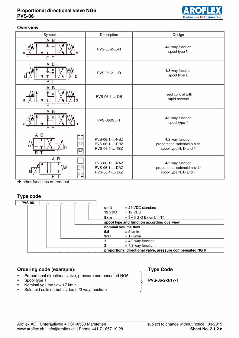
Overview
Symbols Description Design
PVS-06-2-...-N 4/3 way function
spool type N
PVS-06-2-...-D 4/3 way function
spool type D
PVS-06-1-...-DB Feed control with
rapid reverse
PVS-06-2-...-T 4/3 way function
spool type T
PVS-06-1-...-NBZ PVS-06-1-...-DBZ
PVS-06-1-...-TBZ
4/2 way function proportional solenoid b-side
spool type N, D and T
PVS-06-1-...-NAZ
PVS-06-1-...-DAZ PVS-06-1-...-TAZ
4/2 way function
proportional solenoid a-side spool type N, D and T
other functions on request.
Type code
PVS-06 -… -… -… -…
omit = 24 VDC standard
12 VDC = 12 VDC
Exm = II 2 G Ex emb II T4
spool type and function according overview
nominal volume flow
5/5 = 5 l/min 3/17 = 17 l/min
1 = 4/2 way function
2 = 4/3 way function
proportional directional valve, pressure compensated NG 6
Ordering code (example): Type Code
Proportional directional valve, pressure compensated NG6 Spool type T PVS-06-2-3/17-T Nominal volume flow 17 l/min Solenoid coils on both sides (4/3 way function)

Proportional directional valve NG6 PVS-06
Aroflex AG ¦ Unteräuliweg 4 ¦ CH-8560 Märstetten subject to change without notice ¦ 03/2015 www.aroflex.ch ¦ [email protected] ¦ Phone +41 71 657 19 28 Sheet No. 2.1.3.e
Characteristics
Measurement conditions: Hydraulic oil ISO VG 46; Viscosity 46 mm
2/s
Temperature 40...50 °C
0
5
10
15
20
0 100 200 300 400 500 600 700 800 900
Q [l/min]
I [mA]
Q = f (I) Volume flow-signal-characteristics 24VDC Standard at pressure 70 bar
PVS...3/17 PVS...5/5
0
1
2
3
4
5
6
0 50 100 150 200 250
Q [l/min]
p [bar]
Q = f (p) Volume flow-pressure-characteristics PVS...5/5 24VDC Standard
700mA 550mA 400mA
0
5
10
15
20
25
0 50 100 150 200 250
Q [l/min]
p [bar]
Q = f (p) Volume flow-pressure-characteristics PVS...3/17 24VDC Standard
900mA 600mA 400mA

Proportional directional valve NG6 PVS-06
Aroflex AG ¦ Unteräuliweg 4 ¦ CH-8560 Märstetten subject to change without notice ¦ 03/2015 www.aroflex.ch ¦ [email protected] ¦ Phone +41 71 657 19 28 Sheet No. 2.1.4.e
Dimensions
PVS-06-1-5/5-…-…AZ PVS-06-2-5/5-… pictured: proportional solenoid a-side Weight: 2.2 kg Weight: 2.5 kg
PVS-06-1-3/17-…-…BZ PVS-06-2-3/17-… pictured: proportional solenoid b-side Weight: 3.1 kg Weight: 3.8 kg

Proportional directional valve NG6 PVS-06
Aroflex AG ¦ Unteräuliweg 4 ¦ CH-8560 Märstetten subject to change without notice ¦ 03/2015 www.aroflex.ch ¦ [email protected] ¦ Phone +41 71 657 19 28 Sheet No. 2.1.5.e
PVS-06-1-5/5-…-…AZ-Exm pictured: proportional solenoid a-side Weight: 2.6 kg
PVS-06-2-5/5-…-Exm Weight: 3.4 kg

Proportional directional valve NG6 PVD-06
Aroflex AG ¦ Unteräuliweg 4 ¦ CH-8560 Märstetten subject to change without notice ¦ 12/2014 www.aroflex.ch ¦ [email protected] ¦ Tel. +41 71 657 19 28 Sheet No. 2.2.1.e
direct operated
Qmax = 32 l/min
pmax in P, A and B = 315 bar
pmax in T = 160 bar
Description
The proportional valves are used to control direction and flow in hydraulic systems. The applications of these valves ensure any motion sequences at low cost. The PVD valve is a directly controlled spool valve, actuated by proportional solenoids, in five chamber design. The flow rate is proportional to the solenoid current and partly load-compensated.
Application
Examples are acceleration and deceleration move-ments which are difficult to realize with common hy-draulic components. Furthermore with these valves, electric remote controls with manual potentiometer could easily be done. When large control range and optimal load compen-sation is requested we recommend the AROFLEX-proportional directional control valve PVS.
Technical Data
General Specifications PVD…14 PVD…24 PVD…32 PVD...14-Exm PVD...14-Exd
Description: spool valve, direct operated
Mounting position: longitudinal axis horizontal (vertical only after consulting the manufacturer)
Nominal size: NG6, DIN 24340 A 06, ISO 4401-03, Cetop 3
Solenoid coil 24VDC 24VDC 24VDC Exm Exd
Explosion protection marking:
none none none II 2 G Ex emb II T4 II 2 G Ex d IIC T4
Type: 2A52W 2A67W
EC-type examination certificate: PTB 01 ATEX 2129 X PTB 98 ATEX 1009
Ambient temperature: - 20° … + 50°C - 20° … + 40°C - 20° … + 60°C
Rated voltage: 24 VDC ¹ 24 VDC ¹ 24 VDC ¹ 24 VDC 24 VDC
Current range: 0 - 0.68 A 0 - 0.9 A 0 - 0.7 A* 0 - 0.58 A*
Rated power: 16 W 21.6 W 17 W 14 W
Operating time: 100 %
Protection class: IP65 acc. to EN 60 529
Connection: Plug connection ISO 4400/DIN 43650 (2P+E)
Terminal box Terminal box with thread M20x1.5
Amplifier modul: please ask for datasheets
Safety instructions for Exm and Exd
The solenoid coils must only be mounted on those valves assigned to. It is essential to read the solenoids operating instructions.
*It must be ensured to remain within the rated voltage and power, with higher temperatures it’s not possible to utilise the full cur-rent range.
Hydraulic Specifications
Max. volume flow: 14 l/min ² 28 l/min ² 32 l/min 14 l/min ² 14 l/min ²
Min. volume flow: 0.5 l/min 0.8 l/min 0.8 l/min 0.5 l/min 0.5 l/min
Max. pressure: P, A and B 315 bar, T 160 bar
Fluid: Mineral oil, other fluids on request
Fluid temperature: - 20 ... + 70°C - 20 … + 40°C - 20 … + 60°C
Viscosity range: 12 - 320 mm2/s (cSt)
Filtration: 25 µm minimum, recommended: 10 µm or better
Hysteresis: appr. 3% at optimal dither signal
¹ valves with standard coils are available with 12V DC too.
² The maximal volume flow is adjustable to customer requirements, thereby you will have the optimal resolution for your control range.
Proportional directional valve NG6 PVD-06
Aroflex AG ¦ Unteräuliweg 4 ¦ CH-8560 Märstetten subject to change without notice ¦ 03/2015 www.aroflex.ch ¦ [email protected] ¦ Phone +41 71 657 19 28 Sheet No. 2.2.2.e
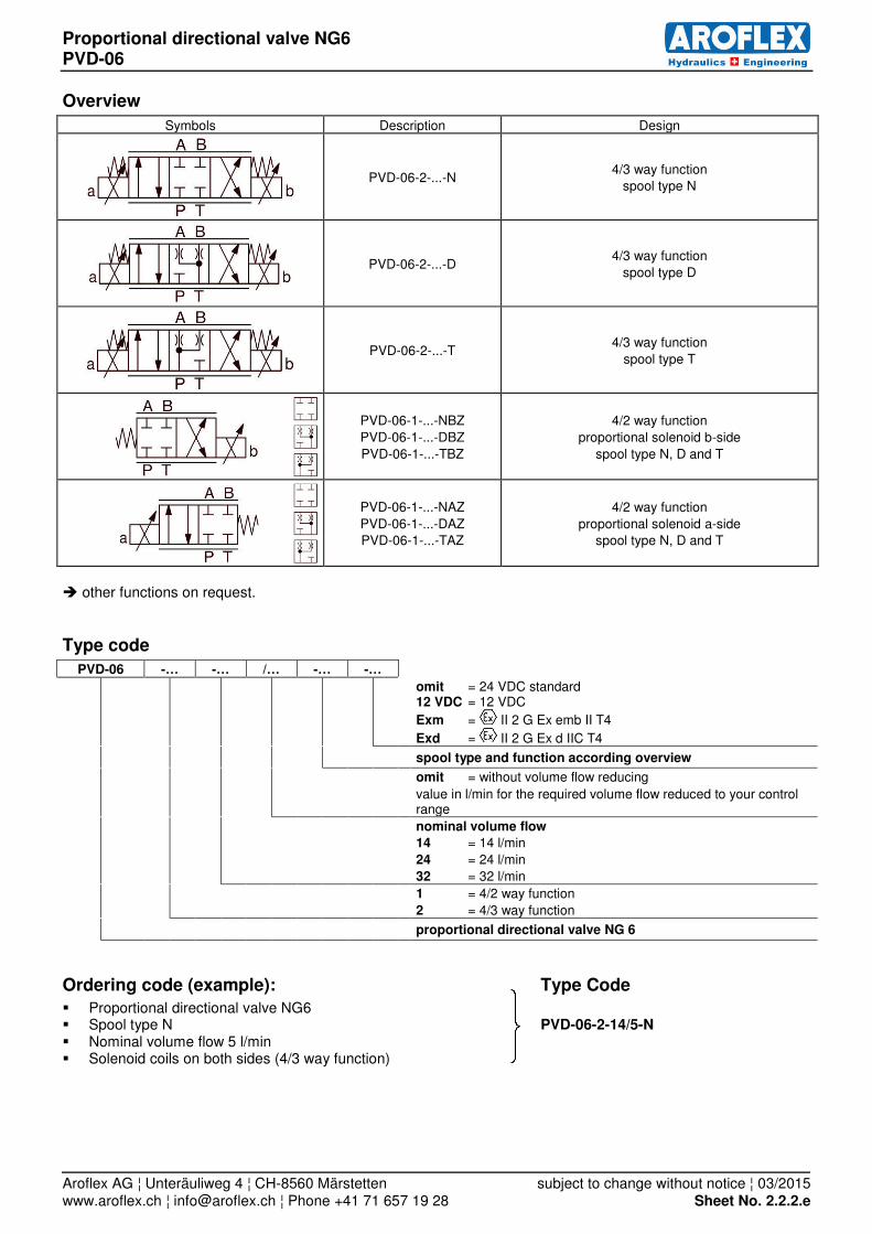
Overview
Symbols Description Design
PVD-06-2-...-N 4/3 way function
spool type N
PVD-06-2-...-D 4/3 way function
spool type D
PVD-06-2-...-T 4/3 way function
spool type T
PVD-06-1-...-NBZ
PVD-06-1-...-DBZ
PVD-06-1-...-TBZ
4/2 way function
proportional solenoid b-side
spool type N, D and T
PVD-06-1-...-NAZ
PVD-06-1-...-DAZ PVD-06-1-...-TAZ
4/2 way function
proportional solenoid a-side spool type N, D and T
other functions on request.
Type code
PVD-06 -… -… /… -… -…
omit = 24 VDC standard 12 VDC = 12 VDC
Exm = II 2 G Ex emb II T4
Exd = II 2 G Ex d IIC T4
spool type and function according overview
omit = without volume flow reducing
value in l/min for the required volume flow reduced to your control range
nominal volume flow
14 = 14 l/min
24 = 24 l/min
32 = 32 l/min
1 = 4/2 way function
2 = 4/3 way function
proportional directional valve NG 6
Ordering code (example): Type Code
Proportional directional valve NG6 Spool type N PVD-06-2-14/5-N Nominal volume flow 5 l/min Solenoid coils on both sides (4/3 way function)

Proportional directional valve NG6 PVD-06
Aroflex AG ¦ Unteräuliweg 4 ¦ CH-8560 Märstetten subject to change without notice ¦ 03/2015 www.aroflex.ch ¦ [email protected] ¦ Phone +41 71 657 19 28 Sheet No. 2.2.3.e
Characteristics
Measurement conditions: Hydraulic oil ISO VG 46; Viscosity 46 mm
2/s
Temperature 40...50 °C
05
10152025303540
0 100 200 300 400 500 600 700 800 900
Q [l/min]
I [mA]
Q = f (I) Volume flow-signal-characteristics at 70 bar
PVD...32 PVD...24
PVD...14-Exm PVD...14
PVD...14-Exd
0
5
10
15
20
0 50 100 150 200 250
Q [l/min]
p [bar]
Q = f (p) Volume flow-pressure-characteristics PVD...14 24VDC Standard
700mA 500mA
300mA
0
5
10
15
20
25
30
35
0 50 100 150 200 250
Q [l/min]
p [bar]
Q = f (p) Volume flow-pressure-characteristics PVD...24 24VDC Standard
900mA
600mA 300mA
0
10
20
30
40
0 50 100 150 200 250
Q [l/min]
p [bar]
Q = f (p) Volume flow-pressure-characteristics PVD...32 24VDC Standard
900mA
600mA 300mA
0
5
10
15
20
0 50 100 150 200 250
Q [l/min]
p [bar]
Q = f (p) Volume flow-pressure-characteristics PVD...14-Exm
700mA
500mA
300mA
0
5
10
15
20
0 50 100 150 200 250
Q [l/min]
p [bar]
Q = f (p) Volume flow-pressure-characteristics PVD...14-Exd
600mA
450mA
300mA

Proportional directional valve NG6 PVD-06
Aroflex AG ¦ Unteräuliweg 4 ¦ CH-8560 Märstetten subject to change without notice ¦ 03/2015 www.aroflex.ch ¦ [email protected] ¦ Phone +41 71 657 19 28 Sheet No. 2.2.4.e
Dimensions
PVD-06-1-14-…AZ PVD-06-2-14-… pictured: proportional solenoid a-side Weight: 1.6 kg Weight: 1.9 kg
PVD-06-1-14-…AZ-Exm PVD-06-2-14-…-Exm pictured: proportional solenoid a-side Weight: 2.1 kg Weight: 2.8 kg

Proportional directional valve NG6 PVD-06
Aroflex AG ¦ Unteräuliweg 4 ¦ CH-8560 Märstetten subject to change without notice ¦ 03/2015 www.aroflex.ch ¦ [email protected] ¦ Phone +41 71 657 19 28 Sheet No. 2.2.5.e
PVD-06-1-14-…AZ-Exd PVD-06-2-14-…-Exd pictured: proportional solenoid a-side Weight: 3.2 kg Weight: 3.9 kg
PVD-06-1-24-…BZ PVD-06-2-24-… pictured: proportional solenoid b-side Weight: 2 kg Weight: 2.7 kg
Order distance plate separately
Order distance plate separately

Proportional directional valve NG6 PVD-06
Aroflex AG ¦ Unteräuliweg 4 ¦ CH-8560 Märstetten subject to change without notice ¦ 03/2015 www.aroflex.ch ¦ [email protected] ¦ Phone +41 71 657 19 28 Sheet No. 2.2.6.e
PVD-06-2-32-N Weight: 2.6 kg

Proportional directional valve NG10 PVS-10
Aroflex AG ¦ Unteräuliweg 4 ¦ CH-8560 Märstetten subject to change without notice ¦ 03/2015 www.aroflex.ch ¦ [email protected] ¦ Phone +41 71 657 19 28 Sheet No. 2.3.1.e
direct operated, pressure compensated Qmax = 60 l/min pmax in P, A and B = 315 bar pmax in T = 160 bar
Description
The proportional valves are used to control direction and flow in hydraulic systems. The applications of these valves ensure any motion sequences at low cost. The PVS valve is a directly controlled spool valve, actuated by proportional solenoids, in five chamber design. The flow rate is proportional to the solenoid current and remains constant with varying pressure. The counterbalance effect ensures that load does not go out of control.
Application
Examples are acceleration and deceleration move-ments which are difficult to realize with common hy-draulic components. PVS valves are characterized by their large flow range. Thereby they are particularly suitable for demanding tasks, e.g. feed control, robo-tic systems, handling operations, etc.
Technical Data
General Specifications PVS…
Description: spool valve, direct operated
Mounting position: longitudinal axis horizontal (vertical only after consulting the manufacturer)
Nominal size: NG10, ISO 4401-05
Solenoid coil 24VDC 12VDC
Ambient temperature: - 20° … + 50°C
Rated voltage: 24 VDC 12 VDC
Current range: 0 – 1.15 A 0 – 2.3 A
Rated power: 22 W 22 W
Operating time: 100 %
Protection class: IP65 acc. to EN 60 529
Connection: Plug connection ISO 4400/DIN 43650 (2P+E)
Amplifier modul: please ask for datasheets
Hydraulic Specifications
Max. volume flow: 30 l/min, 35 l/min, 40 l/min, 45 l/min, 50 l/min, 60 l/min
Min. volume flow: 0.5 l/min
Max. pressure: P, A and B 315 bar, T 160 bar
Fluid: Mineral oil, other fluids on request
Fluid temperature: - 20 ... + 70°C
Viscosity range: 12 - 320 mm2/s (cSt)
Filtration: 25 µm minimum, recommended: 10µm or better
Hysteresis: appr. 2% by optimal dither signal
Proportional directional valve NG10 PVS-10
Aroflex AG ¦ Unteräuliweg 4 ¦ CH-8560 Märstetten subject to change without notice ¦ 03/2015 www.aroflex.ch ¦ [email protected] ¦ Phone +41 71 657 19 28 Sheet No. 2.3.2.e
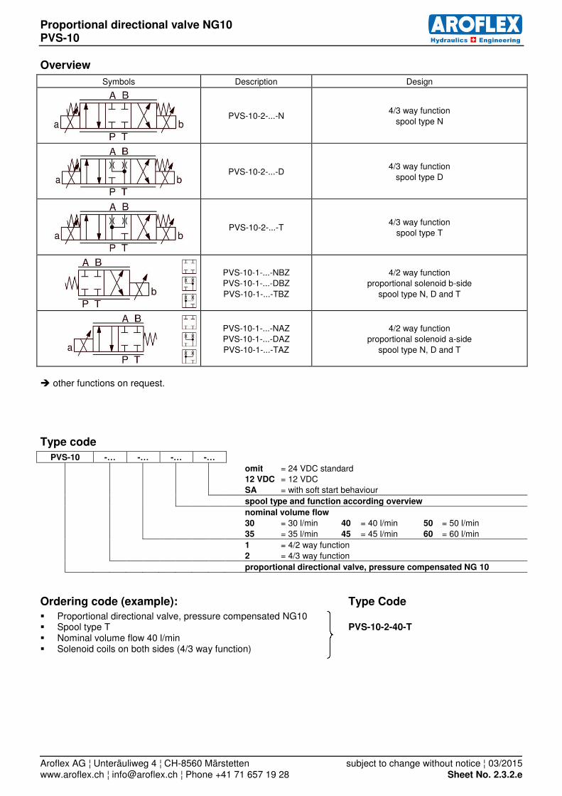
Overview
Symbols Description Design
PVS-10-2-...-N 4/3 way function
spool type N
PVS-10-2-...-D 4/3 way function
spool type D
PVS-10-2-...-T 4/3 way function
spool type T
PVS-10-1-...-NBZ PVS-10-1-...-DBZ
PVS-10-1-...-TBZ
4/2 way function proportional solenoid b-side
spool type N, D and T
PVS-10-1-...-NAZ PVS-10-1-...-DAZ
PVS-10-1-...-TAZ
4/2 way function proportional solenoid a-side
spool type N, D and T
other functions on request.
Type code
PVS-10 -… -… -… -…
omit = 24 VDC standard
12 VDC = 12 VDC
SA = with soft start behaviour
spool type and function according overview
nominal volume flow
30 = 30 l/min 40 = 40 l/min 50 = 50 l/min
35 = 35 l/min 45 = 45 l/min 60 = 60 l/min
1 = 4/2 way function
2 = 4/3 way function
proportional directional valve, pressure compensated NG 10
Ordering code (example): Type Code
Proportional directional valve, pressure compensated NG10 Spool type T PVS-10-2-40-T Nominal volume flow 40 l/min Solenoid coils on both sides (4/3 way function)
Proportional directional valve NG10 PVS-10
Aroflex AG ¦ Unteräuliweg 4 ¦ CH-8560 Märstetten subject to change without notice ¦ 03/2015 www.aroflex.ch ¦ [email protected] ¦ Phone +41 71 657 19 28 Sheet No. 2.3.3.e
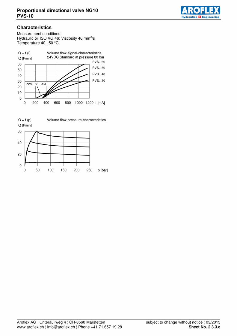
Characteristics
Measurement conditions: Hydraulic oil ISO VG 46; Viscosity 46 mm
2/s
Temperature 40...50 °C
0
10
20
30
40
50
60
0 200 400 600 800 1000 1200
Q [l/min]
I [mA]
Q = f (I) Volume flow-signal-characteristics 24VDC Standard at pressure 80 bar
PVS...60
PVS...50
PVS...40
PVS...30 PVS...60...-SA
0
20
40
60
0 50 100 150 200 250
Q [l/min]
p [bar]
Q = f (p) Volume flow-pressure-characteristics

Proportional directional valve NG10 PVS-10
Aroflex AG ¦ Unteräuliweg 4 ¦ CH-8560 Märstetten subject to change without notice ¦ 03/2015 www.aroflex.ch ¦ [email protected] ¦ Phone +41 71 657 19 28 Sheet No. 2.3.4.e
Dimensions
PVS-10-1-… pictured: proportional solenoid a-side Weight: 5.5 kg
PVS-10-2-… Weight: 7 kg

Proportional directional valve NG10 PVD-10
Aroflex AG ¦ Unteräuliweg 4 ¦ CH-8560 Märstetten subject to change without notice ¦ 03/2015 www.aroflex.ch ¦ [email protected] ¦ Phone +41 71 657 19 28 Sheet No. 2.4.1.e
direct operated Qmax = 50 l/min pmax in P, A and B = 315 bar pmax in T = 160 bar
Description
The proportional valves are used to control direction and flow in hydraulic systems. The applications of these valves ensure any motion sequences at low cost. The PVD valve is a directly controlled spool valve, actuated by proportional solenoids, in five chamber design. The flow rate is proportional to the solenoid current and partly load-compensated.
Application
Examples are acceleration and deceleration move-ments which are difficult to realize with common hy-draulic components. Furthermore with these valves, electric remote controls with manual potentiometer could easily be done. When large control range is requested we recom-mend the AROFLEX-proportional directional control valve PVS.
Technical Data
General Specifications
Description: spool valve, direct operated
Mounting position: any
Nominal size: NG10, DIN 24340 A 10, ISO 4401-05
Solenoid coil 24VDC 12VDC
Ambient temperature: - 20° … + 50°C
Rated voltage: 24 VDC 12 VDC
Current range: 0.05 - 1.15 A 0.1 - 2.3 A
Rated power: 28 W 28 W
Operating time: 100 %
Protection class: IP65 acc. to EN 60 529
Connection: Plug connection ISO 4400/DIN 43650 (2P+E)
Amplifier modul: please ask for datasheets
Hydraulic Specifications
Volume flow at Δp 15 bar:
5 - 50 l/min
Max. pressure: P, A and B 315 bar, T 160 bar
Fluid: Mineral oil, other fluids on request
Fluid temperature: - 20 ... + 70°C
Viscosity range: 12 - 320 mm2/s (cSt)
Filtration: 25 µm minimum, recommended: 10 µm or better
Hysteresis: appr. 3% at optimal dither signal

Proportional directional valve NG10 PVD-10
Aroflex AG ¦ Unteräuliweg 4 ¦ CH-8560 Märstetten subject to change without notice ¦ 03/2015 www.aroflex.ch ¦ [email protected] ¦ Phone +41 71 657 19 28 Sheet No. 2.4.2.e
Overview
Symbols Description Design
PVD-10-2-50-N 4/3 way function
spool type N
PVD-10-2-50-D 4/3 way function
spool type D
PVD-10-2-50-T 4/3 way function
spool type T
PVD-10-1-50-NBZ
PVD-10-1-50-DBZ
PVD-10-1-50-TBZ
4/2 way function
proportional solenoid b-side
spool type N, D and T
PVD-10-1-50-NAZ
PVD-10-1-50-DAZ PVD-10-1-50-TAZ
4/2 way function
proportional solenoid a-side spool type N, D and T
other functions on request.
Type code
PVD-10 -… -50 -… -…
omit = 24 VDC standard 12 VDC = 12 VDC
spool type and function according overview
nominal volume flow
50 = 50 l/min
1 = 4/2 way function
2 = 4/3 way function
proportional directional valve NG 10
Ordering code (example): Type Code
Proportional directional valve NG10 Spool type N PVD-10-2-50-N Solenoid coils on both sides (4/3 way function)

Proportional directional valve NG10 PVD-10
Aroflex AG ¦ Unteräuliweg 4 ¦ CH-8560 Märstetten subject to change without notice ¦ 03/2015 www.aroflex.ch ¦ [email protected] ¦ Phone +41 71 657 19 28 Sheet No. 2.4.3.e
Characteristics
Measurement conditions: Hydraulic oil ISO VG 46; Viscosity 46 mm
2/s
Temperature 40...50 °C
0
10
20
30
40
50
60
0 200 400 600 800 1000
Q [l/min]
I [A]
Q = f (I) Volume flow-signal-characteristics 24VDC standard at 70 bar
0
10
20
30
40
50
60
0 25 50 75 100 125 150 175 200
Q [l/min]
Δp [bar]
Q = f (p) Volume flow-pressure-characteristics 24VDC standard
600 mA
700 mA
500 mA
450 mA
400 mA

Proportional directional valve NG10 PVD-10
Aroflex AG ¦ Unteräuliweg 4 ¦ CH-8560 Märstetten subject to change without notice ¦ 03/2015 www.aroflex.ch ¦ [email protected] ¦ Phone +41 71 657 19 28 Sheet No. 2.4.4.e
Dimensions
PVD-10-1-…AZ pictured: proportional solenoid a-side Weight: 4.5 kg
PVD-10-2-… Weight: 6 kg

Proportional pressure relief valve NG6 EPDB-06
Aroflex AG ¦ Unteräuliweg 4 ¦ CH-8560 Märstetten subject to change without notice ¦ 03/2015 www.aroflex.ch ¦ [email protected] ¦ Phone +41 71 657 19 28 Sheet No. 2.6.1.e
direct operated INVERSE function available Qmax = 20 l/min pmax = 350 bar
Description
EPDB The direct operated proportional pressure relief valve is built as a slip-in cartridge fitted in a connecting flange. By adjusting the electric current to the solenoid the operating pressure changes proportionally. When the operating pressure is reached, the poppet spool opens and connects the protected line to the tank. Back pressure in T influences thereby the pressure in the protected pressure lines. These pressure relief valves are built according to the differential spool principle and are therefore very sensitive adjustable over the whole pressure range and also suitable for systems with extremely low minimum pressures.
The valves have their applications in hydraulic sys-tems in which the pressure frequently has to be changed. The facility for remote control and signal processing from process control systems enable economical solutions for repeatable sequences. EPDB INVERSE Direct operated proportional pressure relief valve. A spring force works against the hydraulic pressure. With solenoid deenergized the maximum operating pressure is present. The force of the proportional so-lenoid counteracts the spring force. With increasing solenoid current the operating pressure declines (in-verse function).
Technical Data
General Specifications EPDB EPDB-12VDC EPDB-Exm EPDB-Exd
Nominal size: NG6, DIN 24340 A 06, ISO 4401-03, Cetop 3
Mounting position: any (solenoid down, only after consulting the manufacturer)
Solenoid coil 24VDC 12 VDC Exm Exd
Explosion protection marking:
none none II 2 G Ex emb II T4 II 2 G Ex d IIC T4
Type: 2A52W 2A67W
EC-type examination certificate: PTB 01 ATEX 2129 X PTB 98 ATEX 1009
Ambient temperature: - 20° ... + 50°C - 20° ... + 40°C - 20° ... + 60°C
Rated voltage: 24 VDC 12 VDC 24 VDC 24 VDC
Current range: 0 - 0.68 A 0 - 1.25 A 0 - 0.7 A* 0 - 0.58 A*
Rated power: 17.5 W 17.5 W 17 W 14 W
Operating time: 100%
Protection class: IP65 acc. to EN 60 529
Connection: Plug connection ISO 4400/DIN 43650 (2P+E)
Terminal box Terminal box with thread M20x1.5
Safety instructions for Exm and Exd
The solenoid coils must only be mounted on those valves assigned to. It is essential to read the solenoids operating instructions.
*It must be ensured to remain within the rated voltage and power, with higher temperatures it’s not possible to utilise the full cur-rent range.
Hydraulic Specifications
Max. volume flow:
Qmax = 20 l/min for pN = 20 / 63 / 100 bar Qmax = 15 l/min for pN = 200 bar
Qmax = 12.5 l/min for pN = 250 bar Qmax = 10 l/min for pN = 315 / 350 bar
Max. pressure: pmax = 315 bar
Fluid: Mineral oil, other fluids on request
Fluid temperature: - 20° ... + 70° C - 20° ... + 40° C - 20° ... + 60° C
Viscosity range: 12 - 320 mm2/s (cSt)
Filtration: 25 m minimum, recommended: 10m or better
Resolution: 1 mA
Repeatability: ≤ 1 % at optimal dither signal Hysteresis: ≤ 2 % at optimal dither signal
INVERS

Proportional pressure relief valve NG6 EPDB-06
Aroflex AG ¦ Unteräuliweg 4 ¦ CH-8560 Märstetten subject to change without notice ¦ 03/2015 www.aroflex.ch ¦ [email protected] ¦ Phone +41 71 657 19 28 Sheet No. 2.6.2.e
Overview
Symbols Description Design
EPDB-…-SD Pressure relief from P to T
flange construction
EPDB-…-SW Pressure relief from P to T
sandwich construction
EPDB-…-INV-SD
Pressure relief from P to T
inverse function
flange construction
EPDB-A-…-SD Pressure relief from A to T
flange construction
EPDB-A-…-INV-SD
Pressure relief from A to T
inverse function flange construction
Type code
EPDB -… -06 -… -… -SD -…
omit = 24 VDC standard
12 VDC = 12 VDC
Exm = II 2 G Ex emb II T4
Exd = II 2 G Ex d IIC T4
SD = flange construction
SW = sandwich construction (INVERSE and A-T on request)
omit = normal function
INV = inverse function
nominal pressure range
20 = 20 bar 100 = 100 bar 250 = 250 bar
63 = 63 bar 200 = 200 bar 315 = 315 bar 350 = 350 bar
06 = NG 6
omit = Pressure relief from P-T
A = Pressure relief from A-T
proportional pressure relief valve, direct operated
Ordering code (example): Type Code
Proportional pressure relief valve NG6 Pressure relief from A to T Nominal pressure range 200 bar EPDB-A-06-200-SD-Exm Flange construction
Explosion proof execution II 2 G Ex emb II T4

Proportional pressure relief valve NG6 EPDB-06
Aroflex AG ¦ Unteräuliweg 4 ¦ CH-8560 Märstetten subject to change without notice ¦ 03/2015 www.aroflex.ch ¦ [email protected] ¦ Phone +41 71 657 19 28 Sheet No. 2.6.3.e
Characteristics and dimensions
oil viscosity ν = 30 mm2/s
EPDB-…-06-… EPDB-…-06-…-INV
EPDB-…-06-…-…-Exm EPDB-…-06-…-INV-…-Exm
EPDB-…-06-…-…-Exd EPDB-…-06-…-INV-…-Exd
0
50
100
150
200
250
300
350
0 100 200 300 400 500 600 700
p [bar]
I [mA]
p = f (I) pressure adjustment characteristics 24VDC standard
350/315 bar 250 bar
200 bar 100 bar
63 bar
20 bar
0
50
100
150
200
250
300
350
0 100 200 300 400 500 600 700
p [bar]
I [mA]
p = f (I) pressure adjustment characteristics INV 24VDC standard
0
50
100
150
200
250
300
350
0 100 200 300 400 500 600 700
p [bar]
I [mA]
p = f (I) pressure adjustment characteristics Exm
250 bar
200 bar
100 bar
63 bar
20 bar
350 / 315 bar
0
50
100
150
200
250
300
350
0 100 200 300 400 500 600
p [bar]
I [mA]
p = f (I) pressure adjustment characteristics INV Exm
0
50
100
150
200
250
300
350
0 100 200 300 400 500 600
p [bar]
I [mA]
p = f (I) pressure adjustment characteristics Exd
200 bar
100 bar
63 bar
20 bar
350 / 315 bar 250 bar
0
50
100
150
200
250
300
350
0 100 200 300 400 500 600
p [bar]
I [mA]
p = f (I) pressure adjustment characteristics INV Exd

Proportional pressure relief valve NG6 EPDB-06
Aroflex AG ¦ Unteräuliweg 4 ¦ CH-8560 Märstetten subject to change without notice ¦ 03/2015 www.aroflex.ch ¦ [email protected] ¦ Phone +41 71 657 19 28 Sheet No. 2.6.4.e
EPDB-…-06-…-SW Weight: 1.2 kg EPDB-…-06-…-SW-Exm Weight: 1.65 kg EPDB-…-06-…-SW-Exd Weight: 2.75 kg
050
100150200250300350400
0 5 10 15 20
p [bar]
Q [l/min]
p = f (Q) Pressure volume flow characteristics (Maximum adjustable pressure)
100 bar 63 bar 20 bar
200 bar
250 bar 315 bar
350 bar
0
5
10
15
20
25
30
0 5 10 15 20
p [bar]
Q [l/min]
p = f (Q) Pressure volume flow characteristics (Minimum adjustable pressure)
100 bar
63 bar
20 bar
200 bar 250 bar 350 / 315 bar
0
10
20
30
40
0 50 100 150 200 250 300 350 p [bar]
QL = f (p) Leakage volume flow characteristics
QL [cm³/min]
Order distance plate 3 / 12 / 30 mm separately

Proportional pressure relief valve NG6 EPDB-06
Aroflex AG ¦ Unteräuliweg 4 ¦ CH-8560 Märstetten subject to change without notice ¦ 03/2015 www.aroflex.ch ¦ [email protected] ¦ Phone +41 71 657 19 28 Sheet No. 2.6.5.e
EPDB-…-06-…-SD EPDB-…-06-…-INV-SD Weight: 1.45 kg Weight: 1.7 kg
EPDB-…-06-…-SD-Exm EPDB-…-06-…-INV-SD-Exm Weight: 1.9 kg Weight: 2.15 kg
EPDB-…-06-…-SD-Exd EPDB-…-06-…-INV- SD-Exd Weight: 3 kg Weight: 3.25 kg
Order distance plate 12 mm separately
Order distance plate 12 mm separately

Proportional pressure relief valve NG6 PEPDB-06
Aroflex AG ¦ Unteräuliweg 4 ¦ CH-8560 Märstetten subject to change without notice ¦ 03/2015 www.aroflex.ch ¦ [email protected] ¦ Phone +41 71 657 19 28 Sheet No. 2.6.8.e
direct operated Qmax = 25 l/min pmax = 400 bar pNmax = 350 bar
Description
The direct operated proportional pressure relief valve is available in flange and sandwich construction ac-cording to ISO 4401-03. Incorporated is a proportion-al pressure relief cartridge size M22x1,5 according to ISO 7789. By adjusting the electric current to the solenoid the operating pressure changes proportionally. When the operating pressure is reached, the poppet spool opens and connects the protected line to the tank. Back pressure in T influences thereby the pressure in
the protected pressure lines. These pressure relief valves are built according to the differential spool principle and are therefore very sensitive adjustable over the whole pressure range and also suitable for systems with extremely low minimum pressures. The valves have their applications in hydraulic sys-tems in which the pressure frequently has to be changed. The facility for remote control and signal processing from process control systems enable economical solutions for repeatable sequences.
Technical Data
General Specifications PEPDB PEPDB-Exm PEPDB-Exd
Mounting position: any (solenoid down, only after consulting the manufacturer)
Nominal size: NG6, DIN 24340 A 06, ISO 4401-03, Cetop 3
Solenoid coil 24VDC Exm Exd
Explosion protection marking:
none II 2 G Ex emb II T4 II 2 G Ex d IIC T4
Type: 2A52W 2A67W
EC-type examination certificate: PTB 01 ATEX 2129 X PTB 98 ATEX 1009
Ambient temperature: - 20° ... + 70°C - 20° ... + 40°C - 20° ... + 60°C
Rated voltage: 24VDC 24VDC 24VDC
Current range: 0 - 0.68 A 0 - 0.7 A* 0 - 0.58 A*
Rated power: 16 W 17 W 14 W
Operating time: 100%
Protection class: IP65 nach EN 60 529
Connection: Plug connection
ISO 4400/DIN 43650 (2P+E) Terminal box
Terminal box with thread M20x1.5
Safety instructions for Exm and Exd
The solenoid coils must only be mounted on those valves assigned to. It is essential to read the solenoids operating instructions.
*It must be ensured to remain within the rated voltage and power, with higher temperatures it is not possible to utilise the full cur-rent range.
Hydraulic Specifications
Max. volume flow:
Qmax = 10 l/min for pN = 350 bar
Qmax = 20 l/min for pN = 315 bar Qmax = 25 l/min for pN = 200 bar, 100 bar and 20 bar
Max. pressure: pmax = 400 bar
Fluid: Mineral oil, other fluids on request
Fluid temperature:: - 20° … + 70° C - 20° … + 40° C - 20° … + 60° C
Viscosity range: 12-320 mm2/s (cSt)
Filtration: 25 m minimum, recommended: 10m or better
Resolution: 1 mA
Repeatability: ≤ 1.5 % at optimal dither signal Hysteresis: ≤ 3 % at optimal dither signal

Proportional pressure relief valve NG6 PEPDB-06
Aroflex AG ¦ Unteräuliweg 4 ¦ CH-8560 Märstetten subject to change without notice ¦ 03/2015 www.aroflex.ch ¦ [email protected] ¦ Phone +41 71 657 19 28 Sheet No. 2.6.9.e
Overview
Symbols Description Design
PEPDB-06-…-SD … Pressure relief from P to T
flange construction
PEPDB-06-…-SW … Pressure relief from P to T
sandwich construction
PEPDB-06-…-SWA … Pressure relief from A to T
sandwich construction
PEPDB-06-…-SWB … Pressure relief from B to T
sandwich construction
PEPDB-06-…-SWAB … Pressure relief from AB to T
sandwich construction
Type code
PEPDB -06 -… -… -…
omit = 24 VDC standard
Exm = II 2 G Ex emb II T4
Exd = II 2 G Ex d IIC T4
SD = flange construction (P → T) SW = sandwich construction (P → T) SWA = sandwich construction (A → T) SWB = sandwich construction (B → T) SWAB = sandwich construction (AB → T)
nominal pressure range
20 = 20 bar 200 = 200 bar 350 = 350 bar 100 = 100 bar 315 = 315 bar
06 = NG 6
proportional pressure relief valve, direct operated
Ordering code (example): Type Code
Proportional pressure relief valve NG6 Pressure relief from P to T PEPDB-06-350-SW-Exm Sandwich construction
Explosion proof execution II 2 G Ex emb II T4

Proportional pressure relief valve NG6 PEPDB-06
Aroflex AG ¦ Unteräuliweg 4 ¦ CH-8560 Märstetten subject to change without notice ¦ 03/2015 www.aroflex.ch ¦ [email protected] ¦ Phone +41 71 657 19 28 Sheet No. 2.6.10.e
Characteristics
oil viscosity ν = 30 mm2/s
0
100
200
300
400
0 100 200 300 400 500 600 700
p [bar]
I [mA]
p = f (I) pressure adjustment characteristics 24 VDC Standard
350 bar 315 bar
200 bar
100 bar 20 bar
0
100
200
300
400
0 100 200 300 400 500 600 700
p [bar]
I [mA]
p = f (I) pressure adjustment characteristics Exm
350 bar 315 bar 200 bar
100 bar
20 bar
0
100
200
300
400
0 100 200 300 400 500 600
p [bar]
I [mA]
p = f (I) pressure adjustment characteristics Exd
200 bar
100 bar
20 bar
315 bar 350 bar
0
100
200
300
400
0 5 10 15 20 25
p [bar]
Q [l/min]
p = f (Q) Pressure volume flow characteristics (Maximum adjustable pressure)
350 bar
315 bar
200 bar 100 bar 20 bar
0
10
20
30
40
0 5 10 15 20 25
p [bar]
Q [l/min]
p = f (Q) Pressure volume flow characteristics (Minimum adjustable pressure)
315 bar 200 bar 100 bar
20 bar
350 bar
0
10
20
30
40
0 50 100 150 200 250 300 350 p [bar]
QL = f (p) Leakage volume flow characteristics
QL [cm³/min]

Proportional pressure relief valve NG6 PEPDB-06
Aroflex AG ¦ Unteräuliweg 4 ¦ CH-8560 Märstetten subject to change without notice ¦ 03/2015 www.aroflex.ch ¦ [email protected] ¦ Phone +41 71 657 19 28 Sheet No. 2.6.11.e
Dimensions
pictured: PEPDB-06-…-SD / SWB pictured: PEPDB-06-…-SD / SWB-Exm Weight: 2 kg Weight: 2.7 kg
pictured: PEPDB-06-…-SD / SWB-Exd Weight: 3.9 kg
Blanking plate only for flange construction
Blanking plate only for flange construction
Order distance plate separately
Order distance plate separately
Order distance plate separately
Blanking plate only for flange construction

Proportional pressure relief valve EPDB-06-Exd-L15
Aroflex AG ¦ Unteräuliweg 4 ¦ CH-8560 Märstetten subject to change without notice ¦ 03/2015 www.aroflex.ch ¦ [email protected] ¦ Phone +41 71 657 19 28 Sheet No. 2.6.20.e
direct operated INVERSE function available Qmax = 20 l/min pmax = 350 bar
Description
EPDB The direct operated proportional pressure relief valve is built as a slip-in cartridge fitted in a connecting flange. By adjusting the electric current to the solenoid the operating pressure changes proportionally. When the operating pressure is reached, the poppet spool opens and connects the protected line to the tank. Back pressure in T influences thereby the pressure in the protected pressure lines. These pressure relief valves are built according to the differential spool principle and are therefore very sensitive adjustable over the whole pressure range and also suitable for systems with extremely low minimum pressures.
The valves have their applications in hydraulic sys-tems in which the pressure frequently has to be changed. The facility for remote control and signal processing from process control systems enable economical solutions for repeatable sequences. EPDB INVERSE Direct operated proportional pressure relief valve. A spring force works against the hydraulic pressure. With solenoid deenergized the maximum operating pressure is present. The force of the proportional so-lenoid counteracts the spring force. With increasing solenoid current the operating pressure declines (in-verse function).
Technical Data
General Specifications EPDB
Nominal size: NG6, DIN 24340 A 06, ISO 4401-03, Cetop 3
Mounting position: any (solenoid down, only after consulting the manu-facturer)
Solenoid coil Exd-L15
Explosion protection marking: II 2 G Ex d IIC T4
Type: MKY45/18x60-G24/L15
EC-type examination certificate: PTB 07 ATEX 1023 IECEx PTB 10.0020
Ambient temperature: - 25° ... + 70°C
Rated voltage: 24 VDC
Rated Power: 15 W
Limiting current: 450mA
Operating time: 100%
Protection class: IP65 acc. to EN 60 529
Connection: Terminal box with thread M20x1.5
Safety instructions for Exd-L15
The solenoid coils must only be mounted on those valves assigned to. It is essential to read the solenoids operating instructions.
Hydraulic Specifications
Max. volume flow:
Qmax = 20 l/min for pN = 20 / 63 / 100 bar Qmax = 15 l/min for pN = 200 bar
Qmax = 12.5 l/min for pN = 250 bar Qmax = 10 l/min for pN = 315 / 350 bar
Max. pressure: pmax = 315 bar
Fluid: Mineral oil, other fluids on request
Fluid temperature: - 20° ... + 70° C
Viscosity range: 12 - 320 mm2/s (cSt)
Filtration: 25 m minimum, recommended: 10m or better
Resolution: 1 mA
Repeatability: ≤ 1 % at optimal dither signal Hysteresis: ≤ 2 % at optimal dither signal
INVERS

Proportional pressure relief valve EPDB-06-Exd-L15
Aroflex AG ¦ Unteräuliweg 4 ¦ CH-8560 Märstetten subject to change without notice ¦ 03/2015 www.aroflex.ch ¦ [email protected] ¦ Phone +41 71 657 19 28 Sheet No. 2.6.21.e
Overview
Symbols Description Design
EPDB-…-SD Pressure relief from P to T
flange construction
EPDB-…-SW Pressure relief from P to T
sandwich construction
EPDB-…-INV-SD
Pressure relief from P to T
inverse function
flange construction
EPDB-A-…-SD Pressure relief from A to T
flange construction
EPDB-A-…-INV-SD
Pressure relief from A to T
inverse function flange construction
Type code
EPDB -… -06 -… -… -SD -…
Exd-L15 = II 2 G Ex d IIC T4
SD = flange construction
SW = sandwich construction (INVERSE and A-T on request)
omit = normal function
INV = inverse function
nominal pressure range
20 = 20 bar 100 = 100 bar 250 = 250 bar
63 = 63 bar 200 = 200 bar 315 = 315 bar 350 = 350 bar
06 = NG 6
omit = Pressure relief from P-T
A = Pressure relief from A-T
proportional pressure relief valve, direct operated
Ordering code (example): Type Code
Proportional pressure relief valve NG6 Pressure relief from A to T Nominal pressure range 200 bar EPDB-A-06-200-SD-Exd-L15 Flange construction
Explosion proof execution II 2 G Ex d IIC T4

Proportional pressure relief valve EPDB-06-Exd-L15
Aroflex AG ¦ Unteräuliweg 4 ¦ CH-8560 Märstetten subject to change without notice ¦ 03/2015 www.aroflex.ch ¦ [email protected] ¦ Phone +41 71 657 19 28 Sheet No. 2.6.22.e
Characteristics
oil viscosity ν = 30 mm2/s
EPDB-…-06-…-…-Exd-L15 EPDB-…-06-…-INV-…-Exd-L15
0
50
100
150
200
250
300
350
0 100 200 300 400 500 600
p [bar]
I [mA]
p = f (I) pressure adjustment characteristics Exd-L15
200 bar
100 bar
63 bar
20 bar
350 / 315 bar 250 bar
0
50
100
150
200
250
300
350
0 100 200 300 400 500 600
p [bar]
I [mA]
p = f (I) pressure adjustment characteristics INV Exd-L15
050
100150200250300350400
0 5 10 15 20
p [bar]
Q [l/min]
p = f (Q) Pressure volume flow characteristics (Maximum adjustable pressure)
100 bar 63 bar 20 bar
200 bar
250 bar 315 bar
350 bar
0
5
10
15
20
25
30
0 5 10 15 20
p [bar]
Q [l/min]
p = f (Q) Pressure volume flow characteristics (Minimum adjustable pressure)
100 bar
63 bar
20 bar
200 bar 250 bar 350 / 315 bar
0
10
20
30
40
0 50 100 150 200 250 300 350 p [bar]
QL = f (p) Leakage volume flow characteristics
QL [cm³/min]

Proportional pressure relief valve EPDB-06-Exd-L15
Aroflex AG ¦ Unteräuliweg 4 ¦ CH-8560 Märstetten subject to change without notice ¦ 03/2015 www.aroflex.ch ¦ [email protected] ¦ Phone +41 71 657 19 28 Sheet No. 2.6.23.e
Dimensions
EPDB-…-06-…-SW-Exd-L15 Weight: 2.55 kg
EPDB-…-06-…-SD-Exd-L15 EPDB-…-06-…-INV- SD-Exd-L15 Weight: 2.8 kg Weight: 3.05 kg
Order distance plate 3 / 12 / 30 mm separately

Proportional pressure reducing valve NG6 DRV-06
Aroflex AG ¦ Unteräuliweg 4 ¦ CH-8560 Märstetten subject to change without notice ¦ 03/2015 www.aroflex.ch ¦ [email protected] ¦ Phone +41 71 657 19 28 Sheet No. 2.7.1.e
direct operated, 3-way pressure reducing valve Qmax = 8 l/min pressure range = 0 - 50 bar body stainless steel (optional)
Description
The proportional pressure reducing valve (3-way function) is used to control pressure and direction in hydraulic systems, where the pressure frequently has to be changed. Proportional to the solenoid current, solenoid force and pressure in port A or B rises. With deenergized solenoid, port A and B are connected to port T (throttled). The valve function is practically in-dependent of the pressure in port P.
The proportional pressure reducing valve can be de-livered with 1 or 2 solenoids. For pressure reducing only in A or B, it needs only one solenoid. For pres-sure reducing in A and B, it needs two solenoids.
Application
A typical application is for example a pilot valve for larger proportional directional control valves.
Technical Data
General Specifications DRV DRV-Exm DRV-Exd
Description: spool valve, direct operated
Mounting position: longitudinal axis horizontal (vertical only after consulting the manufacturer)
Nominal size: NG6, DIN 24340 A 06, ISO 4401-03, Cetop 3
Solenoid coil M35 Standard Exm Exd
Explosion protection marking:
none none II 2 G Ex emb II T4 II 2 G Ex d IIC T4
Type: 2A52W 2A67W
EC-type examination certificate: PTB 01 ATEX 2129 X PTB 98 ATEX 1009
Ambient temperature: - 20° ... + 50°C - 20° ... + 40°C - 20° ... + 60°C
Rated voltage: 24 VDC¹ 24 VDC¹ 24 VDC 24 VDC
Current range: 0 - 0.68 A 0 - 0.9 A 0 - 0.7 A* 0 - 0.58 A*
Rated Power: 16 W 21.6 W 17 W 14 W
Operating time: 100%
Protection class: IP65 acc. to EN 60 529
Connection: Plug connection ISO 4400/DIN 43650 (2P+E)
Terminal box Terminal box with thread M20x1.5
Safety instructions for Exm and Exd
The solenoid coils must only be mounted on those valves assigned to. It is essential to read the solenoids operating instructions. *It must be ensured to remain within the rated voltage and power, with higher temperatures it’s not possible to utilise the full cur-rent range.
Hydraulic Specifications
Max. volume flow: Qmax = 8 l/min
Max. pressure: 315 bar (for optimal control behaviour max. 100 bar)
Pressure range: 0 - 20 bar, 0 - 30 bar
0 - 35 bar,
0 - 50 bar 0 - 20 bar, 0 - 30 bar, 0 - 45 bar
Fluid: Mineral oil, other fluids on request
Fluid temperature: - 20° ... + 70°C - 20° ... + 40°C - 20° ... + 60°C
Viscosity range: 12 - 320 mm2/s (cSt)
Filtration: 25 µm minimum, recommended: 10µm or better
¹ valves with standard coils are available with 12V DC too.

Proportional pressure reducing valve NG6 DRV-06
Aroflex AG ¦ Unteräuliweg 4 ¦ CH-8560 Märstetten subject to change without notice ¦ 03/2015 www.aroflex.ch ¦ [email protected] ¦ Phone +41 71 657 19 28 Sheet No. 2.7.2.e
Overview
Symbols Description Design
DRVAB-06-3-....D Pressure reducing in A and B
(4/3 way function)
DRVA-06-3-....D Pressure reducing in A
(4/2 way function)
DRVB-06-3-....D Pressure reducing in B
(4/2 way function)
Type code
DRV … -06 -3 -… .D -… -…
omit = 24 VDC standard
12 VDC = 12 VDC
M35 = 24 VDC
Exm = II 2 G Ex emb II T4
Exd = II 2 G Ex d IIC T4
omit = standard
316L = body stainless steel
pressure range
20 = 0 - 20 bar 30 = 0 - 30 bar
35 = 0 - 35 bar (standard only)
45 = 0 - 45 bar (Ex only) 50 = 0 - 50 bar (standard only)
06 = NG 6
AB = pressure reducing in A and B A = pressure reducing in A
B = pressure reducing in B
proportional pressure reducing valve
Ordering code (example): Type code
Proportional pressure reducing valve NG6 4/3 way function with pressure reducing in A and B
Explosion proof execution II 2 G Ex emb II T4 DRVAB-06-3-30.D-Exm Pressure range 0 - 30 bar

Proportional pressure reducing valve NG6 DRV-06
Aroflex AG ¦ Unteräuliweg 4 ¦ CH-8560 Märstetten subject to change without notice ¦ 03/2015 www.aroflex.ch ¦ [email protected] ¦ Phone +41 71 657 19 28 Sheet No. 2.7.3.e
Characteristics
0
10
20
30
40
0 100 200 300 400 500 600 700
p [bar]
I [mA]
p = f (I) pressure adjustment characteristics M35
30 bar
20 bar
0
10
20
30
40
50
60
70
0 100 200 300 400 500 600 700 800 900
p [bar]
I [mA]
p = f (I) pressure adjustment characteristics 24VDC standard
35 bar
50 bar
0
10
20
30
40
50
0 100 200 300 400 500 600 700
p [bar]
I [mA]
p = f (I) pressure adjustment characteristics Exm
45 bar
30 bar 20 bar
0
10
20
30
40
50
60
0 100 200 300 400 500 600
p [bar]
I [mA]
p = f (I) pressure adjustment characteristics Exd
30 bar
20 bar
45 bar

Proportional pressure reducing valve NG6 DRV-06
Aroflex AG ¦ Unteräuliweg 4 ¦ CH-8560 Märstetten subject to change without notice ¦ 03/2015 www.aroflex.ch ¦ [email protected] ¦ Phone +41 71 657 19 28 Sheet No. 2.7.4.e
Dimensions
DRVA-06-3-….D-M35 / DRVB-06-3-….D-M35 DRVAB-06-3-….D-M35 pictured: DRVB-06-3-….D-M35 Weight: 1.6 kg Weight: 1.9 kg
DRVA-06-3-….D / DRVB-06-3-….D DRVAB-06-3-….D pictured: DRVB-06-3-….D Weight: 2 kg Weight: 2.7 kg

Proportional pressure reducing valve NG6 DRV-06
Aroflex AG ¦ Unteräuliweg 4 ¦ CH-8560 Märstetten subject to change without notice ¦ 03/2015 www.aroflex.ch ¦ [email protected] ¦ Phone +41 71 657 19 28 Sheet No. 2.7.5.e
DRVA-06-3-….D-Exm / DRVB-06-3-….D-Exm DRVAB-06-3-….D-Exm pictured: DRVB-06-3-….D-Exm Weight: 2.1 kg Weight: 2.8 kg
DRVA-06-3-….D-Exd / DRVB-06-3-….D-Exd DRVAB-06-3-….D-Exd pictured: DRVB-06-3-….D-Exd Weight: 3.2 kg Weight: 5.1 kg

Proportional pressure reducing valve NG6 DRV-06-Exd-L15
Aroflex AG ¦ Unteräuliweg 4 ¦ CH-8560 Märstetten subject to change without notice ¦ 03/2015 www.aroflex.ch ¦ [email protected] ¦ Phone +41 71 657 19 28 Sheet No. 2.7.20.e
direct operated, 3-way pressure reducing valve Qmax = 8 l/min pressure range = 0 - 45 bar body stainless steel (optional)
Description
The proportional pressure reducing valve (3-way function) is used to control pressure and direction in hydraulic systems, where the pressure frequently has to be changed. Proportional to the solenoid current, solenoid force and pressure in port A or B rises. With deenergized solenoid, port A and B are connected to port T (throttled). The valve function is practically in-dependent of the pressure in port P.
The proportional pressure reducing valve can be de-livered with 1 or 2 solenoids. For pressure reducing only in A or B, it needs only one solenoid. For pres-sure reducing in A and B, it needs two solenoids.
Application
A typical application is for example a pilot valve for larger proportional directional control valves.
Technical Data
General Specifications DRV-Exd-L15
Description: spool valve, direct operated
Mounting position: longitudinal axis horizontal
(vertical only after consulting the manufacturer)
Nominal size: NG6, DIN 24340 A 06, ISO 4401-03, Cetop 3
Solenoid coil Exd-L15
Explosion protection marking: II 2 G Ex d IIC T4
Type: MKY45/18x60-G24/L15
EC-type examination certificate: PTB 07 ATEX 1023 IECEx PTB 10.0020
Ambient temperature: - 25° ... + 70°C
Rated voltage: 24 VDC
Rated Power: 15 W
Limiting current: 450mA
Operating time: 100%
Protection class: IP65 acc. to EN 60 529
Connection: Terminal box with thread M20x1.5
Safety instructions for Exd-L15
The solenoid coils must only be mounted on those valves assigned to. It is essential to read the solenoids operating instructions.
Hydraulic Specifications
Max. volume flow: Qmax = 8 l/min
Max. pressure: 315 bar (for optimal control behaviour max. 100 bar)
Pressure range: 0 - 20 bar, 0 - 30 bar, 0 - 45 bar
Fluid: Mineral oil, other fluids on request
Fluid temperature: - 20° ... + 60°C
Viscosity range: 12 - 320 mm2/s (cSt)
Filtration: 25 µm minimum, recommended: 10µm or better

Proportional pressure reducing valve NG6 DRV-06-Exd-L15
Aroflex AG ¦ Unteräuliweg 4 ¦ CH-8560 Märstetten subject to change without notice ¦ 03/2015 www.aroflex.ch ¦ [email protected] ¦ Phone +41 71 657 19 28 Sheet No. 2.7.21.e
Overview
Symbols Description Design
DRVAB-06-3-....D Pressure reducing in A and B
(4/3 way function)
DRVA-06-3-....D Pressure reducing in A
(4/2 way function)
DRVB-06-3-....D Pressure reducing in B
(4/2 way function)
Type code
DRV … -06 -3 -… .D -… -…
Exd-L15 = II 2 G Ex d IIC T4
omit = standard 316L = body stainless steel
pressure range
20 = 0 - 20 bar
30 = 0 - 30 bar 45 = 0 - 45 bar
06 = NG 6
AB = pressure reducing in A and B
A = pressure reducing in A B = pressure reducing in B
proportional pressure reducing valve
Ordering code (example): Type code
Proportional pressure reducing valve NG6 4/3 way function with pressure reducing in A and B
explosion proof execution II 2 G Ex d IIC T4 DRVAB-06-3-30.D-Exd-L15 pressure range 0 - 30 bar

Proportional pressure reducing valve NG6 DRV-06-Exd-L15
Aroflex AG ¦ Unteräuliweg 4 ¦ CH-8560 Märstetten subject to change without notice ¦ 03/2015 www.aroflex.ch ¦ [email protected] ¦ Phone +41 71 657 19 28 Sheet No. 2.7.22.e
Characteristics
Dimensions
DRVA-06-3-….D-Exd-L15 / DRVB-06-3-….D-Exd-L15 drawing for DRVB-06-3-….D-Exd-L15 Weight: 3.0 kg
DRVAB-06-3-….D-Exd-L15 Weight: 4.7 kg
0
10
20
30
40
50
60
0 100 200 300 400 500 600
p [bar]
I [mA]
p = f (I) pressure adjustment characteristics Exd-L15
45 bar 30 bar
20 bar

Directional valve NG6 43/42W-06
Aroflex AG ¦ Unteräuliweg 4 ¦ CH-8560 Märstetten subject to change without notice ¦ 03/2015 www.aroflex.ch ¦ [email protected] ¦ Phone +41 71 657 19 28 Sheet No. 2.8.1.e
direct operated Qmax = 50 l/min pmax = 350 bar
Description
These solenoid valves are mainly used to control the direction of movement as well as to start and stop hy-draulic cylinders and motors. The valves are direct op-erated.
As opposed to the conventional directional valves, this valve finds application in a potentially explosive atmos-phere. They are operated by an explosion-proof sole-noid.
Technical Data
General Specifications 43/42W -Exm 43/42W -Exd
Description: spool valve, direct operated
Mounting position: longitudinal axis horizontal (vertical only after consulting the manufacturer)
Nominal size: NG6, DIN 24340 A 06, ISO 4401-03, Cetop 3
Solenoid coil Exm Exd
Explosion protection marking: II 2 G Ex emb II T4 II 2 G Ex d IIC T4
Type: 2A52W 2A67W
EC-type examination certificate:
PTB 01 ATEX 2129 X PTB 98 ATEX 1009
Ambient temperature: - 20° ... + 40°C - 20° ... + 60°C
Rated voltage: 24 VDC 24 VDC
Current range: 0 - 0.7 A* 0 - 0.58 A*
Rated power: 17 W 14 W
Operating time: 100%
Protection class: IP65 acc. to EN 60 529
Connection: Terminal box Terminal box with thread M20x1.5
Safety instructions for Exm and Exd
The solenoid coils must only be mounted on those valves assigned to. It is essential to read the solenoids operating instructions. *It must be ensured to remain within the rated voltage and power, with higher temperatures it’s not possible to utilise the full cur-rent range.
Hydraulic Specifications
Max. volume flow: see characteristic
Max. pressure in P, A and B: pmax = 350 bar
Max. pressure in T: pmax = 150 bar
Fluid: Mineral oil, other fluids on request
Fluid temperature: - 20° ... + 40° C - 20° ... + 60° C
Viscosity range: 12 - 320 mm2/s (cSt)
Filtration: 25 µm minimum, recommended: 10 µm or better

Directional valve NG6 43/42W-06
Aroflex AG ¦ Unteräuliweg 4 ¦ CH-8560 Märstetten subject to change without notice ¦ 03/2015 www.aroflex.ch ¦ [email protected] ¦ Phone +41 71 657 19 28 Sheet No. 2.8.2.e
Overview
Symbols Description Design
43W-06-1A… 4/3 way function
spool type 1A
43W-06-1B… 4/3 way function
spool type 1B
43W-06-1C… 4/3 way function spool type 1C
43W-06-1D… 4/3 way function
spool type 1D
42W-06A-3A… 4/2 way function solenoid a-side
spool type 3A
42W-06B-3A…
4/2 way function
solenoid b-side spool type 3A
other types on request.
Type code
4…W -06 … -… -…
Exm = II 2 G Ex emb II T4
Exd = II 2 G Ex d IIC T4
spool type and function according overview
omit = 4/3 way function
A = solenoid a-side (only 4/2 way function)
B = solenoid b-side (only 4/2 way function)
06 = NG 6
42W = 4/2 way function
43W = 4/3 way function
Ordering code (example): Type Code
direct operated 4/3 directional valve spool type 1A 43W-06-1A-Exm
explosion-proof solenoid II 2 G Ex emb II T4

Directional valve NG6 43/42W-06
Aroflex AG ¦ Unteräuliweg 4 ¦ CH-8560 Märstetten subject to change without notice ¦ 03/2015 www.aroflex.ch ¦ [email protected] ¦ Phone +41 71 657 19 28 Sheet No. 2.8.3.e
Characteristics
oil viscosity ν = 30 mm2/s
Envelop curve for spool 1D
Envelop curve for spool 3A, 1A, 1C, 1B
0.0
50.0
100.0
150.0
200.0
250.0
300.0
350.0
0 10 20 30 40 50 Q [l/min]
p = f (Q) Performance limits with standard voltage -10%
p [bar]
1A, 1C
1B, 1D
3A
0
5
10
15
20
25
30
0 5 10 15 20 25 30 35 40 45 50 Q [l/min]
Δp = f (Q) Pressure drop volume flow characteristics
Δp [bar]
2
1
3 Spool- type
Volume flow direction
P→A P→B P→T A→T B→T
3A 2 2 - 2 2
1A 2 2 - 2 2
1C 2 2 - 2 2
1D 2 2 3 2 2
1B 1 1 - 1 1
0
30
60
90
120
150
0 50 100 150 200 250 300 350 p [bar]
QL= f (p) Leakage volume flow characteristics per control edge Q [cm3/min]
Directional valve NG6 43/42W-06
Aroflex AG ¦ Unteräuliweg 4 ¦ CH-8560 Märstetten subject to change without notice ¦ 03/2015 www.aroflex.ch ¦ [email protected] ¦ Phone +41 71 657 19 28 Sheet No. 2.8.4.e
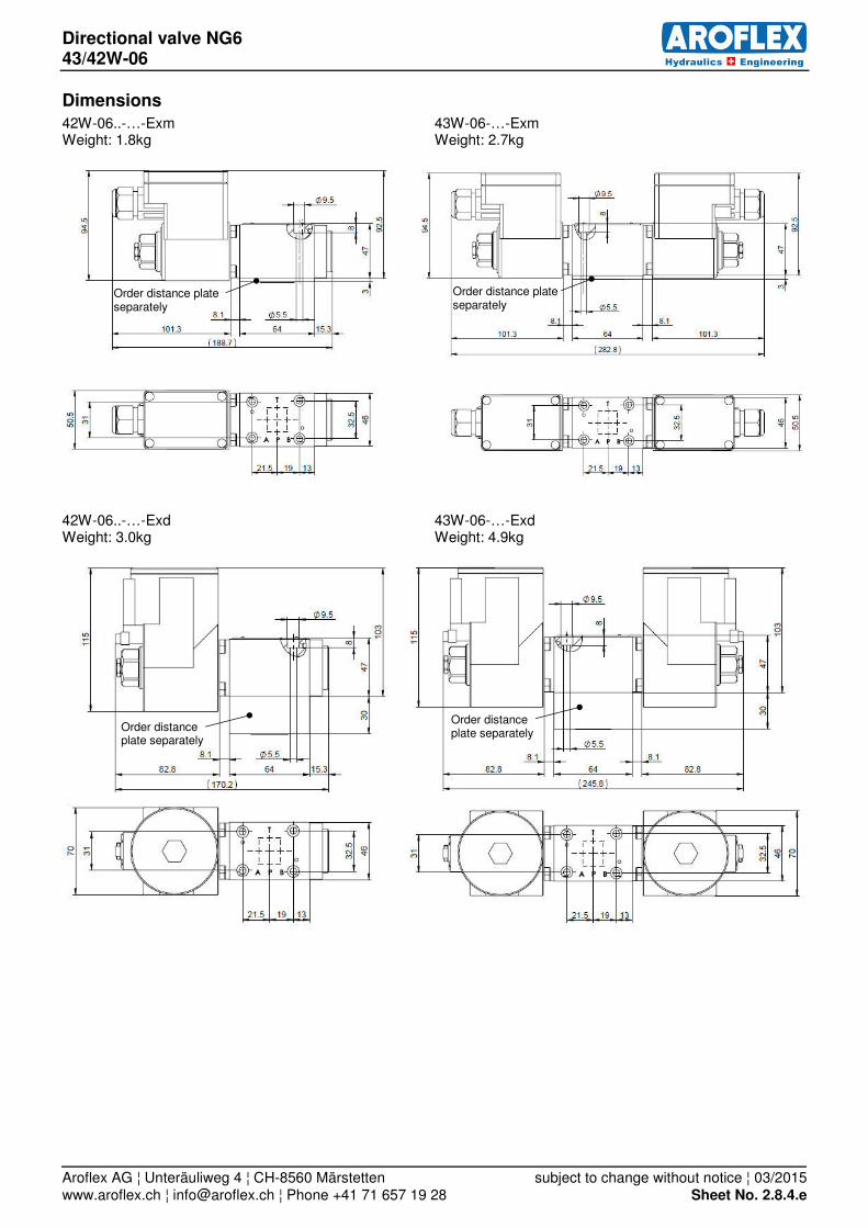
Dimensions
42W-06..-…-Exm 43W-06-…-Exm Weight: 1.8kg Weight: 2.7kg
42W-06..-…-Exd 43W-06-…-Exd Weight: 3.0kg Weight: 4.9kg
Order distance plate separately
Order distance plate separately
Order distance plate separately
Order distance plate separately

Emergency shut off valve NG6 42W-06-…-SSM
Aroflex AG ¦ Unteräuliweg 4 ¦ CH-8560 Märstetten subject to change without notice ¦ 03/2015 www.aroflex.ch ¦ [email protected] ¦ Phone +41 71 657 19 28 Sheet No. 2.9.1.e
manually operated pmax on P, A and B = 350 bar pmax on T = 150 bar Q = 12 l/min
Description
The manually operated 4/2 way valve is often used as a 3/2- way pilot valve to shut off bigger valves. The spool of the valve is held in normal position by spring-loaded balls.
In the actuated position is the valve locked. In order to reset the valve, the green sleeve must be pushed towards the valve body while simultaneously pulling the red push-knob back to its rest position. The valve is protected for use in seawater atmos-phere. Thereby it is an all-purpose valve.
Technical Data
General Specifications 42W-06-…-SSM-…-1
Description: 4/2 way spool valve, manually operated
Actuator: Push-button, relief sleeve
Mounting position: any
Ambient temperature: - 20° ... + 50°C
Nominal size: NG6, DIN 24340 A 06, ISO 4401-03, Cetop 3
Weight: 1.72 kg
Hydraulic Specifications
Nominal flowrate: Q = 12 l/min
Max. pressure on P, A and B: pmax = 350 bar
Max. pressure on T: pmax = 150 bar
Fluid: Mineral oil, other fluids on request
Fluid temperature: - 20° ... + 70° C
Viscosity range: 12 - 320 mm2/s (cSt)
Filtration: 25 m minimum
Internal leakage: see characteristics
Overview
Symbols Description Design
42W-06-3AR-SSM-1
4/2 - way valve, detent
normal position: P – A, B – T actuated position: P – B, A – T
42W-06-3BR-SSM-1
4/2 - way valve, detent
normal position: P – B, A – T actuated position: P – A, B – T
42W-06-…-SSM-E-1 4/2 - way valve, detent
with inductive switch position sensor, N.O., PNP

Emergency shut off valve NG6 42W-06-…-SSM
Aroflex AG ¦ Unteräuliweg 4 ¦ CH-8560 Märstetten subject to change without notice ¦ 03/2015 www.aroflex.ch ¦ [email protected] ¦ Phone +41 71 657 19 28 Sheet No. 2.9.2.e
Type code
42W -06 -… -SSM -… -1 -…
omit = NBR-seals
V = Viton-seals
design status
omit = standard
E = with inductive sensor, N.O., PNP
emergency shut off device
function symbol according overview
06 = mounting interface NG 6
4/2 - way valve
Characteristics
Measured with ISO46 mineral oil at 40°C
Dimensions
42W-06-…-SSM-1 42W-06-…-SSM-E-1
0
10
20
30
40
50
0 50 100 150 200 250 300 p [bar]
QL = f (p) Leakage
QL [cm³/min]
0
5
10
15
20
25
0 5 10 15 20 Q [l/min]
p = f (Q) Pressure drop
p [bar]
A-T, B-T
P-A, P-B

Poppet valve M22x1.5 DP-M22
Aroflex AG ¦ Unteräuliweg 4 ¦ CH-8560 Märstetten subject to change without notice ¦ 03/2015 www.aroflex.ch ¦ [email protected] ¦ Phone +41 71 657 19 28 Sheet No. 2.10.1e
direct operated Qmax = 40 l/min pmax = 350 bar
Description
Direct operated solenoid poppet valve. They are ap-plied where an absolutely leak free closing of the valve is essential like in load holding-, clamping- or gripping functions. These valves are suitable for haz-ardous areas in off-shore and shipbuilding applica-tions as well as in the chemical-, oil- and gas indus-try.
Function
The pressure tight switching solenoid and in turn the spring on the opposite side shift the guided poppet into an either open or closed position. Due to the equal-area- and balanced poppet design there are no undesired opening or closing forces. Fluid may pass the poppet valve in both directions. The poppet pis-ton is sealed by an o-ring. The seat with metallic seal closes leak free in both directions.
Technical Data
General Specifications DP-Exm DP-Exd DP-Exd-L15
Nominal size: M22x1.5 acc. to ISO 7789
Mounting position: any (solenoid down, only after consulting the manufacturer)
Solenoid coil Exm Exd Exd-L15
Explosion protection marking: II 2 G Ex emb II T4 II 2 G Ex d IIC T4 II 2 G Ex d IIC T4
Type: 2A52W 2A67W MKY45/18x60-G24/L15
EC-type examination certificate:
PTB 01 ATEX 2129 X PTB 98 ATEX 1009 PTB 07 ATEX 1023
IECEx PTB 10.0020
Ambient temperature: - 20° ... + 40°C - 20° ... + 60°C - 25° ... + 70°C
Rated voltage: 24 VDC 24 VDC 24 VDC
Current range: 0 - 0.7 A* 0 - 0.58 A* 0 - 0.62 A*
Rated power: 17 W 14 W 10.8 W
Operating time: 100%
Protection class: IP65 acc. to EN 60 529
Connection: Terminal box Terminal box with thread M20x1.5
Terminal box with thread M20x1.5
Safety instructions for Exm and Exd
The solenoid coils must only be mounted on those valves assigned to. It is essential to read the solenoids operating instructions.
*It must be ensured to remain within the rated voltage and power, with higher temperatures it’s not possible to utilise the full cur-rent range.
Hydraulic Specifications
Max. pressure: pmax = 350 bar
Fluid: Mineral oil, other fluids on request
Fluid temperature: - 20° ... + 40° C - 20° ... + 60° C - 20 ... + 70°C
Viscosity range: 12 - 320 mm2/s (cSt)
Required contamination class: 18/16/13 according to ISO 4406: 1999
Recommended filtration grade: β 6…10 ≥ 75

Poppet valve M22x1.5 DP-M22
Aroflex AG ¦ Unteräuliweg 4 ¦ CH-8560 Märstetten subject to change without notice ¦ 03/2015 www.aroflex.ch ¦ [email protected] ¦ Phone +41 71 657 19 28 Sheet No. 2.10.2e
Overview
Symbols Description Design
DP-…-NC-… 2/2 way poppet valve - normally closed
DP-…-NO-… 2/2 way poppet valve - normally open
DP-…-32W-… 3/2 way poppet valve
Type code
DP -… -… -…
Exm = II 2 G Ex emb II T4
Exd = II 2 G Ex d IIC T4
Exd-L15 = II 2 G Ex d IIC T4
or additional identifications
function
NC = 2/2 way - normally closed NO = 2/2 way - normally open
32W = 3/2 way
version
PM22 = Cartridge M22x1.5
M22x1.5 = with inline body M22x1.5 / G1/2” solenoid poppet valve
Ordering code (example): Type Code
2/2-way poppet valve with inline body M22x1.5 / G1/2” DP-M22x1.5-NC-Exm normally closed
Explosion proof execution II 2 G Ex emb II T4
Transitional function

Poppet valve M22x1.5 DP-M22
Aroflex AG ¦ Unteräuliweg 4 ¦ CH-8560 Märstetten subject to change without notice ¦ 03/2015 www.aroflex.ch ¦ [email protected] ¦ Phone +41 71 657 19 28 Sheet No. 2.10.3e
Characteristics and Dimensions
oil viscosity ν = 30 mm2/s
DP-…-NC / NO-Exm / Exd DP-…-32W-Exm / Exd
valve volume flow direction
1 → 2 2 → 1
DP-…-NC-Exm 1 4
DP-…-NC-Exd 1 1
DP-…-NC-Exd-L15 3 4
DP-…-NO-Exm 5 4
DP-…-NO-Exd 5 1
DP-…-NO-Exd-L15 5 2
DP-PM22-NC / NO-Exm Weight: 1.3 kg Cavity acc. to ISO 7789–22–01–0–98 DP-PM22-NC / NO-Exd Weight: 2.5 kg Cavity acc. to ISO 7789–22–01–0–98 DP-PM22-NC / NO-Exd-L15 Weight: 2.2 kg Cavity acc. to ISO 7789–22–01–0–98 DP-PM22-32W-Exm Weight: 1.3 kg Cavity acc. to ISO 7789–22–04–0–98 DP-PM22-32W-Exd Weight: 2.5 kg Cavity acc. to ISO 7789–22–04–0–98 DP-PM22-32W-Exd-L15 Weight: 2.2 kg Cavity acc. to ISO 7789–22–04–0–98
0
50
100
150
200
250
300
350
0 5 10 15 20 25 30 35 40 Q [l/min]
p = f (Q) Performance limits with standard voltage -10% p [bar]
1 2 3 4 5
0
50
100
150
200
250
300
350
0 2 4 6 8 10 12 14 16 18 20 Q [l/min]
p = f (Q) Performance limits with standard voltage -10% p [bar]
1 2 3 4 5
6
0
5
10
15
20
25
30
35
0 5 10 15 20 25 30 35 40 Q [l/min]
p = f (Q) Pressure drop volume flow chrarcteristics
p [bar]
1 2 3
4
valve volume flow direction
1 → 2 2 → 1 2 → 3 3 → 2
DP-…-32W-Exm 5 1 4 6
DP-…-32W-Exd 3 1 2 5
DP-…-32W-Exd-L15 5 1 4 6
valve volume flow direction
1 → 2 2 → 1 2 → 3 3 → 2
DP-…-NC-… 1 2 - -
DP-…-NO-… 3 4 - -
DP-…-32W-… - 4 1 1

Poppet valve M22x1.5 DP-M22
Aroflex AG ¦ Unteräuliweg 4 ¦ CH-8560 Märstetten subject to change without notice ¦ 03/2015 www.aroflex.ch ¦ [email protected] ¦ Phone +41 71 657 19 28 Sheet No. 2.10.4e
DP-M22x1.5-NC / NO-Exm Weight: 2.7 kg
DP-M22x1.5-NC / NO-Exd Weight: 4 kg
DP-M22x1.5-NC / NO-Exd-L15 Weight: 3.7 kg
DP-M22x1.5-32W-Exm Weight: 3.7 kg DP-M22x1.5-32W-Exd Weight: 5 kg DP-M22x1.5-32W-Exd-L15 Weight: 4.7 kg

Poppet valve NG6 DP-06
Aroflex AG ¦ Unteräuliweg 4 ¦ CH-8560 Märstetten subject to change without notice ¦ 03/2015 www.aroflex.ch ¦ [email protected] ¦ Phone +41 71 657 19 28 Sheet No. 2.11.1.e
direct operated Qmax = 40 l/min pmax = 350 bar
Description
Direct operated solenoid poppet valve. They are ap-plied where an absolutely leak free closing of the valve is essential like in load holding-, clamping- or gripping functions. These valves are suitable for haz-ardous areas in off-shore and shipbuilding applica-tions as well as in the chemical-, oil- and gas indus-try.
Function
The pressure tight switching solenoid and in turn the spring on the opposite side shift the guided poppet into an either open or closed position. Due to the equal-area- and balanced poppet design there are no undesired opening or closing forces. Fluid may pass the poppet valve in both directions. The poppet pis-ton is sealed by an o-ring. The seat with metallic seal closes leak free in both directions.
Technical Data
General Specifications DP-Exm DP-Exd
Nominal size: NG6, DIN 24340 A 06, ISO 4401-03, Cetop 3
Mounting position: any (solenoid down, only after consulting the manufacturer)
Solenoid coil Exm Exd
Explosion protection marking: II 2 G Ex emb II T4 II 2 G Ex d IIC T4
Type: 2A52W 2A67W
EC-type examination certificate:
PTB 01 ATEX 2129 X PTB 98 ATEX 1009
Ambient temperature: - 20° ... + 40°C - 20° ... + 60°C
Rated voltage: 24 VDC 24 VDC
Current range: 0 - 0.7 A* 0 - 0.58 A*
Rated power: 17 W 14 W
Operating time: 100%
Protection class: IP65 acc. to EN 60 529
Connection: Terminal box Terminal box with thread M20x1.5
Safety instructions for Exm and Exd
The solenoid coils must only be mounted on those valves assigned to. It is essential to read the solenoids operating instructions. *It must be ensured to remain within the rated voltage and power, with higher temperatures it’s not possible to utilise the full cur-rent range.
Hydraulic Specifications
Max. pressure: pmax = 350 bar
Fluid: Mineral oil, other fluids on request
Fluid temperature: - 20° ... + 40° C - 20° ... + 60° C
Viscosity range: 12 - 320 mm2/s (cSt)
Required contamination class: 18/16/13 according to ISO 4406: 1999
Recommended filtration grade: β 6…10 ≥ 75
Poppet valve NG6 DP-06
Aroflex AG ¦ Unteräuliweg 4 ¦ CH-8560 Märstetten subject to change without notice ¦ 03/2015 www.aroflex.ch ¦ [email protected] ¦ Phone +41 71 657 19 28 Sheet No. 2.11.2.e
Overview
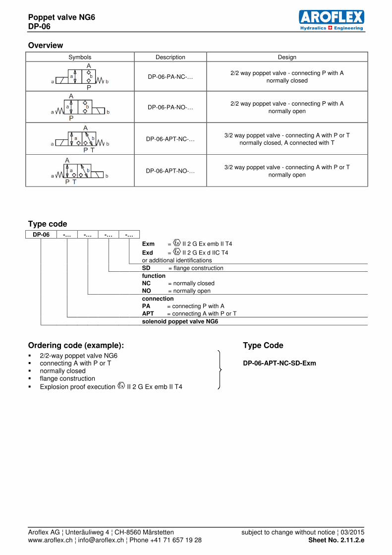
Symbols Description Design
DP-06-PA-NC-… 2/2 way poppet valve - connecting P with A
normally closed
DP-06-PA-NO-… 2/2 way poppet valve - connecting P with A
normally open
DP-06-APT-NC-… 3/2 way poppet valve - connecting A with P or T
normally closed, A connected with T
DP-06-APT-NO-… 3/2 way poppet valve - connecting A with P or T
normally open
Type code
DP-06 -… -… -… -…
Exm = II 2 G Ex emb II T4
Exd = II 2 G Ex d IIC T4
or additional identifications
SD = flange construction
function
NC = normally closed
NO = normally open
connection
PA = connecting P with A
APT = connecting A with P or T
solenoid poppet valve NG6
Ordering code (example): Type Code
2/2-way poppet valve NG6 connecting A with P or T DP-06-APT-NC-SD-Exm normally closed flange construction
Explosion proof execution II 2 G Ex emb II T4

Poppet valve NG6 DP-06
Aroflex AG ¦ Unteräuliweg 4 ¦ CH-8560 Märstetten subject to change without notice ¦ 03/2015 www.aroflex.ch ¦ [email protected] ¦ Phone +41 71 657 19 28 Sheet No. 2.11.3.e
Characteristics and Dimensions
oil viscosity ν = 30 mm2/s
DP-06-PA-… -SD-Exm / Exd DP-06-APT-…-SD-Exm / Exd
valve
volume flow direction
P → A A → P
DP-06-PA-NC-SD-Exm 1 3
DP-06-PA-NO-SD-Exm 1 4
DP-06-PA-NC-SD-Exd 1 1
DP-06-PA-NO-SD-Exd 1 2
0
50
100
150
200
250
300
350
0 5 10 15 20 25 30 35 40 Q [l/min]
p = f (Q) Performance limits with standard voltage -10% p [bar] 1
2 3 4
0
50
100
150
200
250
300
350
0 5 10 15 20 25 30 35 40 Q [l/min]
p = f (Q) Performance limits with standard voltage -10% p [bar]
1 2 3 4
5
6
7
0
5
10
15
20
25
30
35
0 5 10 15 20 25 30 35 40 Q [l/min]
p = f (Q) Pressure drop volume flow characteristics p [bar]
valve volume flow direction
P → A A → T A → P T → A
DP-06-APT-NC-SD-Exm 1 2 7 1
DP-06-APT-NO-SD-Exm 1 3 5 1
DP-06-APT-NC-SD -Exd 1 1 6 1
DP-06-APT-NO-SD -Exd 1 1 4 1

Poppet valve NG6 DP-06
Aroflex AG ¦ Unteräuliweg 4 ¦ CH-8560 Märstetten subject to change without notice ¦ 03/2015 www.aroflex.ch ¦ [email protected] ¦ Phone +41 71 657 19 28 Sheet No. 2.11.4.e
DP-06-PA / APT-…-SD-Exm pictured: DP-06-…-NC-SD-Exm (DP-06-…-NO-SD-Exm: solenoid on b-side) Weight: 2.4 kg
E = air bleed screw
DP-06-PA / APT-…-SD-Exd pictured: DP-06-…-NC-SD-Exd (DP-06-…-NO-SD-Exd: solenoid on b-side) Weight: 3.6 kg
E = air bleed screw
order distance plate seperately
E
order distance plate seperately 12 or 30mm
E

Hydraulic valves
Aroflex AG ¦ Unteräuliweg 4 ¦ CH-8560 Märstetten 09.04.2015www.aroflex.ch ¦ [email protected] ¦ Phone +41 71 657 19 28


![QA Automation Battle: Java vs Python vs Ruby [09.04.2015]](https://static.documents.pub/doc/80x56/55b79a6bbb61eb78558b4652/qa-automation-battle-java-vs-python-vs-ruby-09042015.jpg)


