20
B Hydraulics Quick Coupling Division 8145 Lewis Road • Minneapolis, MN 55427 www.parker.com/quickcouplings B-1 Hydraulic Quick Couplings
BH
ydra
ulic
s
Quick Coupling Division8145 Lewis Road • Minneapolis, MN 55427
www.parker.com/quickcouplingsB-1
HydraulicQuick
Couplings
Quick Coupling Division8145 Lewis Road • Minneapolis, MN 55427
www.parker.com/quickcouplingsB-2
Hydraulic Quick Couplings
BH
ydra
ulic
s
Introduction
Double Shut-Off and Straight-Thru Couplings
Parker hydraulic couplings have a wide variety of designs,each tailored to a particular application or use. This catalog isarranged according to those categories. In each section theconstruction of a specific design will be detailed. However,based on the valving of the coupling, hydraulic couplingsgenerally fall into one of two groups, either Double Shut-Offor Straight-Thru.
Double Shut-Off couplings are used extensively when it isimportant to minimize fluid loss upon disconnection. Bothhalves of the coupler, the body and the nipple, contain shut-
off valves. These valves open automatically when the bodyand nipple are connected, and close automatically when thetwo halves are disconnected—keeping fluid loss to aminimum.
Parker Straight-Thru couplings have no valves in either halfand are ideal for maximum flow application. Their smooth,open bore offers the lowest pressure drop of any quickdisconnect coupling, and allows them to be thoroughlycleaned. Since there are no valves in either half, fluid flowshould be shut off before the coupling is disconnected.
Rated Pressure
Rated pressure for the Parker hydraulic couplings range from30 to 15,000 psi, depending on the coupling series, size andmaterials. Rated pressures as shown in this catalog aredefined by ISO 5598, as “the qualified operating pressureswhich are recommended for a component or a system by themanufacturer.” Parker “Rated Pressures” have beenestablished on the basis of laboratory tests which include, butare not limited to, static burst tests and multiple cycle impulsetests. System characteristics such as high cycling rates andhigh amplitude shocks either hydraulic or mechanical, canreduce the functioning life of a coupling,
even if the system’s nominal pressure falls within the ratedpressure range of the coupling.
For assistance in analyzing your application, contact yournearest Parker sales office or the Quick Coupling Division in Minneapolis.
Refer to the Safety Guide at the end of this catalog forconsiderations when selecting a Quick Coupling.
Refer to the Fluid Compatibility Chart (note Table of Contents)for seal selection assistance for both Double Shut-Off andStraight-Thru couplings.
Checklist for Selecting Quick Couplings
� What are the functional requirements of the coupling?
� What is the maximum working pressure of the application?
� Which seals and body material are compatible with the system’s fluid?
� Is the application static or dynamic?
� What size coupler is required?
� What is the maximum pressure drop suitable for the application?
� Does the application require the ability to connect and disconnect under pressure?
� What is the media temperature and ambient temperature?
� What end configurations are required?
� Is an industry interchange coupler required?
� Is air inclusion and fluid loss a concern in the application?
Quick Coupling Division8145 Lewis Road • Minneapolis, MN 55427
www.parker.com/quickcouplingsB-3
Hydraulic Quick Couplings
BH
ydra
ulic
s
Table of Contents
Introduction .............................................................B-2Coupling Selection Guide......................................B-4General Purpose Couplings60 Series.............................................................B-5–8Couplers............................................................B-7–8Nipples ..............................................................B-7–8
Repair Kits & Replacement Parts ...........................B-8 60 Series Steam .....................................................B-9Couplers................................................................B-9Nipples ..................................................................B-9
6600 Series.....................................................B-10–11Couplers..............................................................B-11Nipples ................................................................B-11
SM Series .......................................................B-12–13Couplers..............................................................B-13Nipples ................................................................B-13
HP Series........................................................B-14–15Couplers..............................................................B-15Nipples ................................................................B-15
4000 Series.....................................................B-16–17Couplers..............................................................B-17Nipples ................................................................B-17
4200 Series......................................................B-18-19Couplers..............................................................B-19Nipples ................................................................B-19
Non-Spill CouplingsNS Series.........................................................B-20-21Couplers..............................................................B-21Nipples ................................................................B-21
Adapters................................................................B-22FF Series .........................................................B-23-24Couplers..............................................................B-24Nipples ................................................................B-24
FEM Series ......................................................B-25-26Couplers..............................................................B-26Nipples ................................................................B-26
FC Series ..............................................................B-27Nipples ................................................................B-27
FEC Series............................................................B-28Nipples ................................................................B-28
FH Series.........................................................B-29-30Couplers..............................................................B-30Nipples ................................................................B-30
FS Series .........................................................B-31-32Couplers..............................................................B-32Nipples ................................................................B-32Repair Kits...........................................................B-32
Connect Under Pressure Couplings6100 Series......................................................B-33-35Couplers.........................................................B-34-35Nipples...........................................................B-34-35
8200 Series......................................................B-36-37Couplers..............................................................B-37Nipples ................................................................B-37
9200 Series......................................................B-38-39Couplers..............................................................B-39Nipples ................................................................B-39
5000 Series......................................................B-40-41Couplers..............................................................B-41Nipples ................................................................B-41
High Pressure Couplings3000 Series......................................................B-42-43Couplers..............................................................B-43Nipples ................................................................B-43
TC Series ..............................................................B-44Couplers..............................................................B-44Nipples ................................................................B-44
1141 Series...........................................................B-45Mold Coolant Line CouplingsMoldmate Series..............................................B-46-50Couplers.........................................................B-47-48Sub Assemblies & Replacement Parts ...............B-48Nipples...........................................................B-49-50
High Flow CouplingsST Series .........................................................B-51-53Couplers..............................................................B-52Nipples ................................................................B-53
Water Service........................................................B-54HO Series..............................................................B-55
Special Purpose - Miniature DM Series.......................................................B56-B57
Dust Plugs and Dust Caps ............................B-58-60Ordering Information ...........................................B-61Promotional Products-Keychains .......................B-62
Quick Coupling Division8145 Lewis Road • Minneapolis, MN 55427
www.parker.com/quickcouplingsB-4
Hydraulic Quick Couplings
BH
ydra
ulic
s
Coupling Selection & Ordering Guide
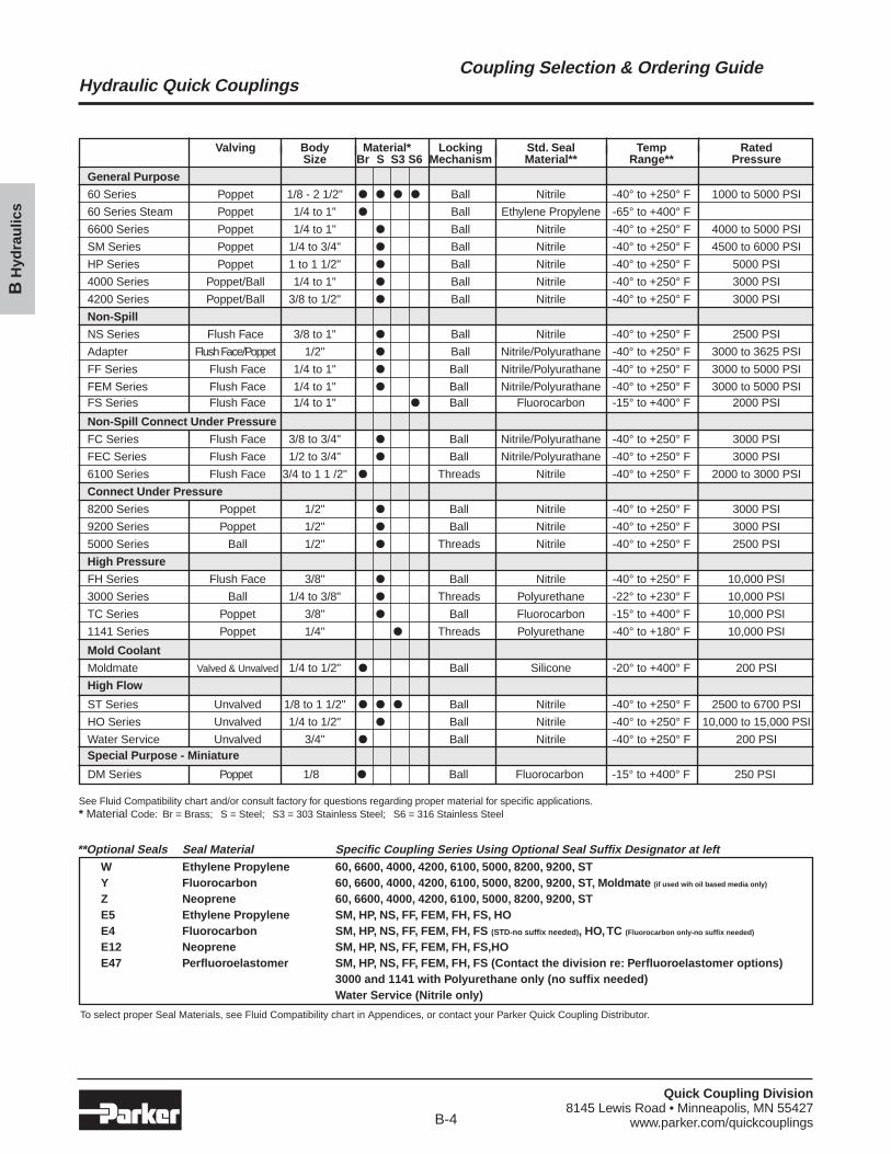
**Optional Seals Seal Material Specific Coupling Series Using Optional Seal Suffix Designator at leftW Ethylene Propylene 60, 6600, 4000, 4200, 6100, 5000, 8200, 9200, STY Fluorocarbon 60, 6600, 4000, 4200, 6100, 5000, 8200, 9200, ST, Moldmate (if used wih oil based media only)
Z Neoprene 60, 6600, 4000, 4200, 6100, 5000, 8200, 9200, STE5 Ethylene Propylene SM, HP, NS, FF, FEM, FH, FS, HOE4 Fluorocarbon SM, HP, NS, FF, FEM, FH, FS (STD-no suffix needed), HO,TC (Fluorocarbon only-no suffix needed)
E12 Neoprene SM, HP, NS, FF, FEM, FH, FS,HOE47 Perfluoroelastomer SM, HP, NS, FF, FEM, FH, FS (Contact the division re: Perfluoroelastomer options)
3000 and 1141 with Polyurethane only (no suffix needed)Water Service (Nitrile only)
To select proper Seal Materials, see Fluid Compatibility chart in Appendices, or contact your Parker Quick Coupling Distributor.
Valving Body Material* Locking Std. Seal Temp RatedSize Br S S3 S6 Mechanism Material** Range** Pressure
General Purpose
60 Series Poppet 1/8 - 2 1/2" � � � � Ball Nitrile -40° to +250° F 1000 to 5000 PSI
60 Series Steam Poppet 1/4 to 1" � Ball Ethylene Propylene -65° to +400° F
6600 Series Poppet 1/4 to 1" � Ball Nitrile -40° to +250° F 4000 to 5000 PSI
SM Series Poppet 1/4 to 3/4" � Ball Nitrile -40° to +250° F 4500 to 6000 PSI
HP Series Poppet 1 to 1 1/2" � Ball Nitrile -40° to +250° F 5000 PSI
4000 Series Poppet/Ball 1/4 to 1" � Ball Nitrile -40° to +250° F 3000 PSI
4200 Series Poppet/Ball 3/8 to 1/2" � Ball Nitrile -40° to +250° F 3000 PSI
Non-Spill
NS Series Flush Face 3/8 to 1" � Ball Nitrile -40° to +250° F 2500 PSI
Adapter Flush Face/Poppet 1/2" � Ball Nitrile/Polyurathane -40° to +250° F 3000 to 3625 PSI
FF Series Flush Face 1/4 to 1" � Ball Nitrile/Polyurathane -40° to +250° F 3000 to 5000 PSI
FEM Series Flush Face 1/4 to 1" � Ball Nitrile/Polyurathane -40° to +250° F 3000 to 5000 PSIFS Series Flush Face 1/4 to 1" � Ball Fluorocarbon -15° to +400° F 2000 PSI
Non-Spill Connect Under Pressure
FC Series Flush Face 3/8 to 3/4" � Ball Nitrile/Polyurathane -40° to +250° F 3000 PSI
FEC Series Flush Face 1/2 to 3/4" � Ball Nitrile/Polyurathane -40° to +250° F 3000 PSI
6100 Series Flush Face 3/4 to 1 1 /2" � Threads Nitrile -40° to +250° F 2000 to 3000 PSI
Connect Under Pressure
8200 Series Poppet 1/2" � Ball Nitrile -40° to +250° F 3000 PSI
9200 Series Poppet 1/2" � Ball Nitrile -40° to +250° F 3000 PSI
5000 Series Ball 1/2" � Threads Nitrile -40° to +250° F 2500 PSI
High Pressure
FH Series Flush Face 3/8" � Ball Nitrile -40° to +250° F 10,000 PSI
3000 Series Ball 1/4 to 3/8" � Threads Polyurethane -22° to +230° F 10,000 PSI
TC Series Poppet 3/8" � Ball Fluorocarbon -15° to +400° F 10,000 PSI
1141 Series Poppet 1/4" � Threads Polyurethane -40° to +180° F 10,000 PSI
Mold Coolant
Moldmate Valved & Unvalved 1/4 to 1/2" � Ball Silicone -20° to +400° F 200 PSI
High Flow
ST Series Unvalved 1/8 to 1 1/2" � � � Ball Nitrile -40° to +250° F 2500 to 6700 PSI
HO Series Unvalved 1/4 to 1/2" � Ball Nitrile -40° to +250° F 10,000 to 15,000 PSI
Water Service Unvalved 3/4" � Ball Nitrile -40° to +250° F 200 PSISpecial Purpose - Miniature
DM Series Poppet 1/8 � Ball Fluorocarbon -15° to +400° F 250 PSI
See Fluid Compatibility chart and/or consult factory for questions regarding proper material for specific applications.* Material Code: Br = Brass; S = Steel; S3 = 303 Stainless Steel; S6 = 316 Stainless Steel
Quick Coupling Division8145 Lewis Road • Minneapolis, MN 55427
www.parker.com/quickcouplingsB-5
Hydraulic Quick Couplings
BH
ydra
ulic
s
General Purpose Couplings60 Series
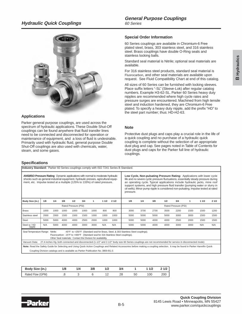
Applications
Parker general purpose couplings, are used across thespectrum of hydraulic applications. These Double Shut-Offcouplings can be found anywhere that fluid transfer linesneed to be connected and disconnected for operation ormaintenance of equipment, and a loss of fluid is undesirable.Primarily used with hydraulic fluid, general purpose DoubleShut-Off couplings are also used with chemicals, water,steam, and some gases.
Special Order Information
60 Series couplings are available in Chromium-6 Freeplated steel, brass, 303 stainless steel, and 316 stainlesssteel. Brass couplings have double O-Ring seals and stainless locking balls.
Standard seal material is Nitrile; optional seal materials areavailable.
For 316 stainless steel products, standard seal material isFluorocarbon, and other seal materials are available uponrequest. See Fluid Compatibility Chart at end of this catalog.
All sizes of 60 Series can be furnished with locking sleeves.Place suffix letters “-SL” (Sleeve-Lok) after regular catalognumbers. Example H3-62-SL. Parker 60 Series heavy dutynipples are recommended where high cycle rates andpressure surges are encountered. Machined from high tensilesteel and induction hardened, they are Chromium-6 Freeplated. To specify a heavy duty nipple, add the prefix “HD” tothe steel part number; thus: HD-H2-63.
Note
Protective dust plugs and caps play a crucial role in the life ofa quick coupling and no purchase of a hydraulic quickcoupling is complete without the selection of an appropriatedust plug and cap. See pages noted in Table of Contents fordust plugs and caps for the Parker full line of hydrauliccouplings.
Seal Temperature Range: Nitrile: -40°F to +250°F (Standard seal for Brass, Steel, & 303 Stainless Steel couplings).Fluorocarbon: -15°F to +400°F (Standard seal for 316 Stainless Steel couplings).Other Seal materials: Contact the Division for availability.
Vacuum Data: 27.4 inches Hg. both connected and disconnected (1-1/2" and 2-1/2" body size 60 Series couplings are not recommended for service in disconnected mode)
Note: Read the Safety Guide for Selecting and Using Quick Action Couplings and Related Accessories before making a coupling selection. It may be found in Parker Hannifin Quick
Coupling Division catalogs and is available as Parker Publication No. 3800-B1.0.
1/8 1/4 3/8 1/2 3/4 1 1 1/2 2 1/2
Rated Pressure (PSI)
3000 3700 2700 3500 2200 1500 1500 1200
5000 5000 5000 5000 3000 3000 1500 1500
5000 5000 4000 4000 2500 2000 1500 1500
5000 5000 4000 4000 3000 3000 N/A N/A
Body Size (in.) 1/8 1/4 3/8 1/2 3/4 1 1 1/2 2 1/2
Rated Flow (GPM) .8 3 6 12 28 50 100 200
Low Cycle, Non-pulsating Pressure Rating: Applications with lower cyclelife and no severe cyclic pressure fluctuations, essentially steady pressure duringan operating cycle. Typical applications include hydraulic jacks, mine roofsupport systems, and high pressure fluid transfer (pumping water or slurry inoil wells). Minor pump ripple is considered non-pulsating. Impulse tested at ratedpressure.
ANSI/ISO Pressure Rating: Dynamic applications with normal to moderate hydraulicshocks such as general industrial equipment, hydraulic presses, agricultural equip-ment, etc. Impulse tested at a multiple (125% to 133%) of rated pressure.
Body Size (in.) 1/8 1/4 3/8 1/2 3/4 1 1 1/2 2 1/2
Rated Pressure (PSI)
Brass 1000 1000 1000 1000 1000 1000 800 800
Stainless steel 2000 2000 1500 1500 1500 1000 1000 1000
Steel 5000 5000 4000 4000 2500 2000 1000 1000
Steel w / HD N/A 5000 4000 4000 3000 3000 N/A N/Anipple
SpecificationsIndustry Standard: Parker 60 Series couplings comply with ISO 7241 Series B Standard.
Quick Coupling Division8145 Lewis Road • Minneapolis, MN 55427
www.parker.com/quickcouplingsB-6
Hydraulic Quick Couplings
BH
ydra
ulic
s
General Purpose Couplings60 Series
2
6
3
1
5 1
7 2
8
4
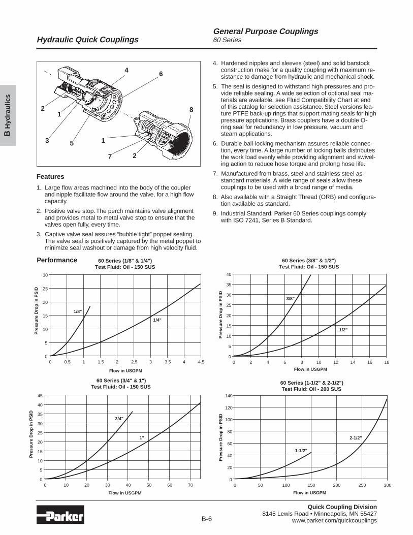
Features
1. Large flow areas machined into the body of the couplerand nipple facilitate flow around the valve, for a high flowcapacity.
2. Positive valve stop. The perch maintains valve alignmentand provides metal to metal valve stop to ensure that thevalves open fully, every time.
3. Captive valve seal assures “bubble tight” poppet sealing.The valve seal is positively captured by the metal poppet tominimize seal washout or damage from high velocity fluid.
4. Hardened nipples and sleeves (steel) and solid barstockconstruction make for a quality coupling with maximum re-sistance to damage from hydraulic and mechanical shock.
5. The seal is designed to withstand high pressures and pro-vide reliable sealing. A wide selection of optional seal ma-terials are available, see Fluid Compatibility Chart at endof this catalog for selection assistance. Steel versions fea-ture PTFE back-up rings that support mating seals for highpressure applications. Brass couplers have a double O-ring seal for redundancy in low pressure, vacuum andsteam applications.
6. Durable ball-locking mechanism assures reliable connec-tion, every time. A large number of locking balls distributesthe work load evenly while providing alignment and swivel-ing action to reduce hose torque and prolong hose life.
7. Manufactured from brass, steel and stainless steel asstandard materials. A wide range of seals allow thesecouplings to be used with a broad range of media.
8. Also available with a Straight Thread (ORB) end configura-tion available as standard.
9. Industrial Standard: Parker 60 Series couplings complywith ISO 7241, Series B Standard.
Performance 60 Series (1/8" & 1/4")Test Fluid: Oil - 150 SUS
0
5
10
15
20
25
30
0 0.5 1 1.5 2 2.5 3 3.5 4 4.5
Flow in USGPM
Pre
ssu
re D
rop
in P
SID
1/8"
1/4"
60 Series (3/8" & 1/2")Test Fluid: Oil - 150 SUS
0
5
10
15
20
25
30
35
40
0 2 4 6 8 10 12 14 16 18
Flow in USGPM
Pre
ssu
re D
rop
in P
SID
3/8"
1/2"
60 Series (3/4" & 1")Test Fluid: Oil - 150 SUS
0
5
10
15
20
25
30
35
40
45
0 10 20 30 40 50 60 70
Flow in USGPM
Pre
ssu
re D
rop
in P
SID
3/4"
1"
60 Series (1-1/2" & 2-1/2")Test Fluid: Oil - 200 SUS
0
20
40
60
80
100
120
140
0 50 100 150 200 250 300
Flow in USGPM
Pre
ssu
re D
rop
in P
SID
1-1/2"
2-1/2"
Quick Coupling Division8145 Lewis Road • Minneapolis, MN 55427
www.parker.com/quickcouplingsB-7
Hydraulic Quick Couplings
BH
ydra
ulic
s
General Purpose Couplings60 Series
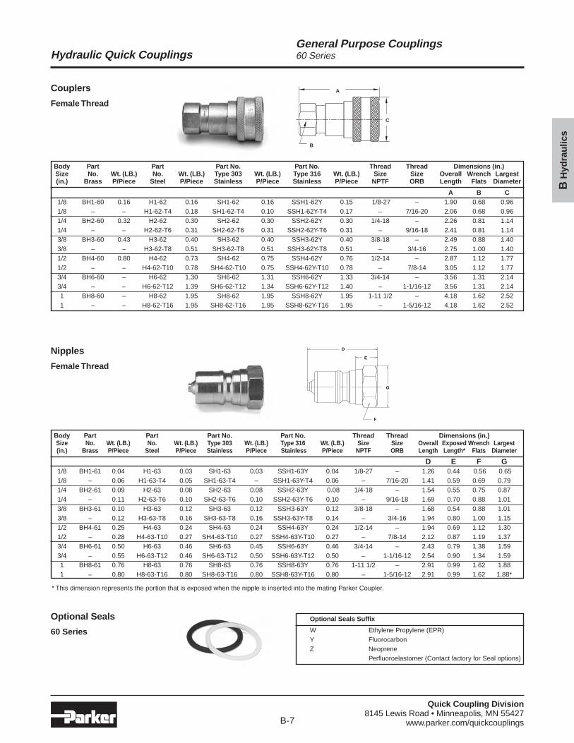
Couplers
Female Thread
Nipples
Female Thread
A
C
B
D
E
G
F
Optional Seals
60 Series
Body Part Part Part No. Part No. Thread Thread Dimensions (in.)Size No. Wt. (LB.) No. Wt. (LB.) Type 303 Wt. (LB.) Type 316 Wt. (LB.) Size Size Overall Wrench Largest(in.) Brass P/Piece Steel P/Piece Stainless P/Piece Stainless P/Piece NPTF ORB Length Flats Diameter
A B C1/8 BH1-60 0.16 H1-62 0.16 SH1-62 0.16 SSH1-62Y 0.15 1/8-27 – 1.90 0.68 0.961/8 – – H1-62-T4 0.18 SH1-62-T4 0.10 SSH1-62Y-T4 0.17 – 7/16-20 2.06 0.68 0.961/4 BH2-60 0.32 H2-62 0.30 SH2-62 0.30 SSH2-62Y 0.30 1/4-18 – 2.26 0.81 1.141/4 – – H2-62-T6 0.31 SH2-62-T6 0.31 SSH2-62Y-T6 0.31 – 9/16-18 2.41 0.81 1.143/8 BH3-60 0.43 H3-62 0.40 SH3-62 0.40 SSH3-62Y 0.40 3/8-18 – 2.49 0.88 1.403/8 – – H3-62-T8 0.51 SH3-62-T8 0.51 SSH3-62Y-T8 0.51 – 3/4-16 2.75 1.00 1.401/2 BH4-60 0.80 H4-62 0.73 SH4-62 0.75 SSH4-62Y 0.76 1/2-14 – 2.87 1.12 1.771/2 – – H4-62-T10 0.78 SH4-62-T10 0.75 SSH4-62Y-T10 0.78 – 7/8-14 3.05 1.12 1.773/4 BH6-60 – H6-62 1.30 SH6-62 1.31 SSH6-62Y 1.33 3/4-14 – 3.56 1.31 2.143/4 – – H6-62-T12 1.39 SH6-62-T12 1.34 SSH6-62Y-T12 1.40 – 1-1/16-12 3.56 1.31 2.141 BH8-60 – H8-62 1.95 SH8-62 1.95 SSH8-62Y 1.95 1-11 1/2 – 4.18 1.62 2.521 – – H8-62-T16 1.95 SH8-62-T16 1.95 SSH8-62Y-T16 1.95 – 1-5/16-12 4.18 1.62 2.52
Body Part Part Part No. Part No. Thread Thread Dimensions (in.)Size No. Wt. (LB.) No. Wt. (LB.) Type 303 Wt. (LB.) Type 316 Wt. (LB.) Size Size Overall Exposed Wrench Largest(in.) Brass P/Piece Steel P/Piece Stainless P/Piece Stainless P/Piece NPTF ORB Length Length* Flats Diameter
D E F G1/8 BH1-61 0.04 H1-63 0.03 SH1-63 0.03 SSH1-63Y 0.04 1/8-27 – 1.26 0.44 0.56 0.651/8 – 0.06 H1-63-T4 0.05 SH1-63-T4 – SSH1-63Y-T4 0.06 – 7/16-20 1.41 0.59 0.69 0.791/4 BH2-61 0.09 H2-63 0.08 SH2-63 0.08 SSH2-63Y 0.08 1/4-18 – 1.54 0.55 0.75 0.871/4 – 0.11 H2-63-T6 0.10 SH2-63-T6 0.10 SSH2-63Y-T6 0.10 – 9/16-18 1.69 0.70 0.88 1.013/8 BH3-61 0.10 H3-63 0.12 SH3-63 0.12 SSH3-63Y 0.12 3/8-18 – 1.68 0.54 0.88 1.013/8 – 0.12 H3-63-T8 0.16 SH3-63-T8 0.16 SSH3-63Y-T8 0.14 – 3/4-16 1.94 0.80 1.00 1.151/2 BH4-61 0.25 H4-63 0.24 SH4-63 0.24 SSH4-63Y 0.24 1/2-14 – 1.94 0.69 1.12 1.301/2 – 0.28 H4-63-T10 0.27 SH4-63-T10 0.27 SSH4-63Y-T10 0.27 – 7/8-14 2.12 0.87 1.19 1.373/4 BH6-61 0.50 H6-63 0.46 SH6-63 0.45 SSH6-63Y 0.46 3/4-14 – 2.43 0.79 1.38 1.593/4 – 0.55 H6-63-T12 0.46 SH6-63-T12 0.50 SSH6-63Y-T12 0.50 – 1-1/16-12 2.54 0.90 1.34 1.591 BH8-61 0.76 H8-63 0.76 SH8-63 0.76 SSH8-63Y 0.76 1-11 1/2 – 2.91 0.99 1.62 1.881 – 0.80 H8-63-T16 0.80 SH8-63-T16 0.80 SSH8-63Y-T16 0.80 – 1-5/16-12 2.91 0.99 1.62 1.88*
Optional Seals Suffix
W Ethylene Propylene (EPR)Y FluorocarbonZ Neoprene
Perfluoroelastomer (Contact factory for Seal options)
* This dimension represents the portion that is exposed when the nipple is inserted into the mating Parker Coupler.
Quick Coupling Division8145 Lewis Road • Minneapolis, MN 55427
www.parker.com/quickcouplingsB-8
Hydraulic Quick Couplings
BH
ydra
ulic
s
General Purpose Couplings60 Series
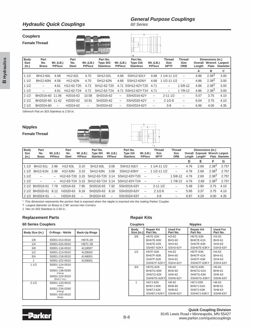
Couplers
Female ThreadC
A
B
D
E
G
F
Nipples
Female Thread
Replacement Parts
60 Series Couplers
Repair Kits
Body Part Part Part No. Part No. Thread Thread Dimensions (in.)Size No. Wt. (LB.) No. Wt. (LB.) Type 303 Wt. (LB.) Type 316 Wt. (LB.) Size Size Overall Exposed Wrench Largest(in.) Brass P/Piece Steel P/Piece Stainless P/Piece Stainless P/Piece NPTF ORB Length Length* Flats Diameter
D E F G
1 1/2 BH12-61L 2.96 H12-63L 3.10 SH12-63L 3.06 SSH12-63LY – 1 1/4-11 1/2 – 4.76 2.69 2.38‡ 2.75†
1 1/2 BH12-61N 2.96 H12-63N 3.10 SH12-63N 3.06 SSH12-63NY – 1 1/2-11 1/2 – 4.76 2.69 2.38‡ 2.75†
1 1/2 – – H12-63-T20 3.15 SH12-63-T20 3.14 SSH12-63Y-T20 – – 1 5/8-12 4.76 2.69 2.38‡ 2.75†
1 1/2 – – H12-63-T24 3.15 SH12-63-T24 3.14 SSH12-63Y-T24 – – 1 7/8-12 4.76 2.69 2.38‡ 2.75†
2 1/2 BH2016-61 7.78 H2016-63 7.90 SH2016-63 7.92 SSH2016-63Y – 2-11 1/2 – 5.48 2.90 3.75 4.10
2 1/2 BH2020-61 8.12 H2020-63 8.16 SH2020-63 8.16 SSH2020-63Y – 2 1/2-8 – 5.95 3.37 3.75 4.10
2 1/2 BH2024-61 – H2024-63 – SH2024-63 – SSH2024-63Y – 3-8 – 6.87 4.29 4.00 4.35
* This dimension represents the portion that is exposed when the nipple is inserted into the mating Parker Coupler.† Largest diameter on Brass is 2.96" across Hex Corners‡ Hex on 303 Stainless is 2.50 in.
Body Part Part Part No. Part No. Thread Thread Dimensions (in.)Size No. Wt. (LB.) No. Wt. (LB.) Type 303 Wt. (LB.) Type 316 Wt. (LB.) Size Size Overall Wrench Largest(in.) Brass P/Piece Steel P/Piece Stainless P/Piece Stainless P/Piece NPTF ORB Length Flats Diameter
A B C
1 1/2 BH12-60L 4.58 H12-62L 4.70 SH12-62L 4.68 SSH12-62LY 4.68 1 1/4-11 1/2 – 4.86 2.38‡ 3.00
1 1/2 BH12-60N 4.58 H12-62N 4.70 SH12-62N 4.68 SSH12-62NY 4.68 1 1/2-11 1/2 – 4.86 2.38‡ 3.00
1 1/2 – 4.61 H12-62-T20 4.72 SH12-62-T20 4.71 SSH12-62Y-T20 4.71 – 1 5/8-12 4.86 2.38‡ 3.00
1 1/2 – 4.61 H12-62-T24 4.72 SH12-62-T24 4.71 SSH12-62Y-T24 4.71 – 1 7/8-12 4.86 2.38‡ 3.00
2 1/2 BH2016-60 11.06 H2016-62 10.58 SH2016-62 – SSH2016-62Y – 2-11 1/2 – 5.57 3.75 4.10
2 1/2 BH2020-60 11.42 H2020-62 10.91 SH2020-62 – SSH2020-62Y – 2 1/2-8 – 6.04 3.75 4.10
2 1/2 BH2024-60 – H2024-62 – SH2024-62 – SSH2024-62Y – 3-8 – 6.96 4.00 4.35
‡Wrench Flat on 303 Stainless is 2.50 in.
Body Size (in.) O-Rings - Nitrile Back-Up Rings
1/8 50001-013-0010 H67A-281/4 50001-015-0010 H67C-283/8 50001-116-0010 41180071/2 50001-213-0010 41280023/4 50001-218-0010 41480011 50001-222-0010 4158001
1-1/2 50001-124-0010(Valve)
50001-138-0260(Fitting)
50001-224-0010(Body 2 req.)
2-1/2 50001-133-0010(Valve)
50001-234-0260(Fitting)
50001-333-0010(Body)
Couplers Nipples
Body Repair Kit Used For Repair Kit Used ForSize (in.) Part No. Part No. Part No. Part No.
3/8 H67E-62K H3-62 H67E-63K H3-63BH67E-60K BH3-60 BH67E-61K BH3-61SH67E-62K SH3-62 SH67E-63K SH3-63SSH67-62KY SSH3-62Y SSH67E-63KY SSH3-63Y
1/2 H67F-62K H4-62 H67F-63K H4-63BH67F-60K BH4-60 BH67F-61K BH4-61SH67F-62K SH4-62 SH67F-63K SH4-63SSH67F-62KY SSH4-62Y SSH67F-63KY SSH4-63Y
3/4 H67G-62K H6-62 H67G-63K H6-63BH67G-60K BH6-60 BH67G-61K BH6-61SH67G-62K SH6-62 SH67G-63K SH6-63SSH67G-62KY SSH6-62Y SSH67G-63KY SSH6-63Y
1 H67J-62K H8-62 H67J-63K H8-63BH67J-60K BH8-60 BH67J-61K BH8-61SH67J-62K SH8-62 SH67J-63K SH8-63SSH67J-62KY SSH8-62Y SSH67J-63KY SSH8-63Y
Quick Coupling Division8145 Lewis Road • Minneapolis, MN 55427
www.parker.com/quickcouplingsB-9
Hydraulic Quick Couplings
BH
ydra
ulic
s
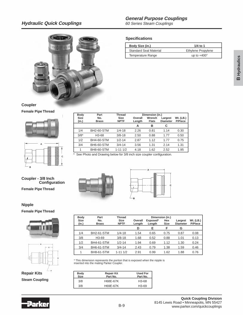
General Purpose Couplings60 Series Steam Couplings
Repair Kits
Steam Coupling
Nipple
Female Pipe Thread
D
E
F
G
Specifications
Body Size (in.) 1/4 to 1
Standard Seal Material Ethylene Propylene
Temperature Range up to +400°
Body Repair Kit Used ForSize Part No. Part No.
3/8 H68E-67K H3-68
3/8 H69E-67K H3-69
Body Part Thread Dimension (in.)Size No. Size Overall Wrench Largest Wt. (LB.)(in.) Brass NPTF Length Flats Diameter P/Piece
A B C
1/4 BH2-60-STM 1/4-18 2.26 0.81 1.14 0.30
3/8* H3-68 3/8-18 2.50 0.88 1.77 0.50
1/2 BH4-60-STM 1/2-14 2.87 1.12 1.77 0.75
3/4 BH6-60-STM 3/4-14 3.56 1.31 2.14 1.31
1 BH8-60-STM 1-11 1/2 4.18 1.62 2.52 1.95
* See Photo and Drawing below for 3/8 inch size coupler configuration.
Body Part Thread Dimension (in.)Size No. Size Overall Exposed* Hex Largest Wt. (LB.)(in.) Brass NPTF Length Length Size Diameter P/Piece
D E F G
1/4 BH2-61-STM 1/4-18 1.54 0.65 0.75 0.87 0.08
3/8 H3-69 3/8-18 1.68 0.52 0.88 1.01 0.13
1/2 BH4-61-STM 1/2-14 1.94 0.69 1.12 1.30 0.24
3/4 BH6-61-STM 3/4-14 2.43 0.79 1.38 1.59 0.46
1 BH8-61-STM 1-11 1/2 2.91 0.99 1.62 1.88 0.76
A
C
B
Coupler - 3/8 Inch Configuration
Female Pipe Thread
A
C
B
* This dimension represents the portion that is exposed when the nipple isinserted into the mating Parker Coupler.
Coupler
Female Pipe Thread
Quick Coupling Division8145 Lewis Road • Minneapolis, MN 55427
www.parker.com/quickcouplingsB-10
Hydraulic Quick Couplings
BH
ydra
ulic
s
General Purpose Couplings6600 Series
Performance
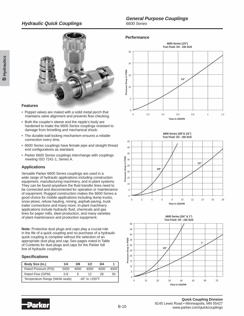
Features
• Poppet valves are mated with a solid metal perch thatmaintains valve alignment and prevents flow checking.
• Both the coupler's sleeve and the nipple's body arehardened to make the 6600 Series couplings resistant todamage from brinelling and mechanical shock.
• The durable-ball-locking mechanism ensures a reliableconnection every time.
• 6600 Series couplings have female pipe and straight threadend configurations as standard.
• Parker 6600 Series couplings interchange with couplingsmeeting ISO 7241-1, Series A.
Applications
Versatile Parker 6600 Series couplings are used in a wide range of hydraulic applications including constructionequipment, manufacturing machinery, and in-plant systems.They can be found anywhere the fluid transfer lines need tobe connected and disconnected for operation or maintenanceof equipment. Rugged construction makes the 6600 Series agood choice for mobile applications including dump trucks,snow plows, refuse hauling, mining, asphalt paving, trucktrailer connections and many more. In-plant machineryapplications include hydraulic fluid, chemicals and gas lines for paper mills, steel production, and many varieties of plant maintenance and production equipment.
Note: Protective dust plugs and caps play a crucial role in the life of a quick coupling and no purchase of a hydraulicquick coupling is complete without the selection of anappropriate dust plug and cap. See pages noted in Table of Contents for dust plugs and caps for the Parker full line of hydraulic couplings.
Specifications
Body Size (in.) 1/4 3/8 1/2 3/4 1
Rated Pressure (PSI) 5000 4000 4000 4000 4000
Rated Flow (GPM) 0.8 6 12 28 50
Temperature Range (Nitrile seals) -40˚ to +250˚F
6600 Series (1/4")Test Fluid: Oil - 150 SUS
0
5
10
15
20
25
0 0.2 0.4 0.6 0.8 1 1.2
Flow in USGPM
Pre
ssu
re D
rop
in
PS
ID
1/4"
6600 Series (3/8"& 1/2")Test Fluid: Oil - 150 SUS
0
5
10
15
20
25
30
35
40
45
0 2 4 6 8 10 12 14 16 18
Flow in USGPM
Pre
ssu
re D
rop
in
PS
ID
3/8"
1/2"
6600 Series (3/4" & 1")Test Fluid: Oil - 150 SUS
0
5
10
15
20
25
30
35
40
45
50
0 10 20 30 40 50 60 70
Flow in USGPM
Pre
ssu
re D
rop
in
PS
ID
3/4"
1"
Quick Coupling Division8145 Lewis Road • Minneapolis, MN 55427
www.parker.com/quickcouplingsB-11
Hydraulic Quick Couplings
BH
ydra
ulic
s
General Purpose Couplings6600 Series
Couplers
Female Thread
Nipples
Female Thread
Replacement Parts
6600 Series
A
C
B
D
E
G
F
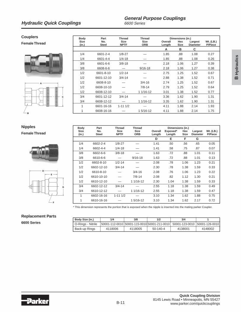
Body Part Thread Thread Dimensions (in.)Size No. Size Size Overall Hex Largest Wt. (LB.)(in.) Steel NPTF ORB Length Size Diameter P/Piece
A B C
1/4 6601-2-4 1/8-27 — 1.85 .88 1.08 0.27
1/4 6601-4-4 1/4-18 — 1.85 .88 1.08 0.26
3/8 6601-6-6 3/8-18 — 2.18 1.06 1.27 0.39
3/8 6608-6-6 — 9/16-18 2.18 1.06 1.27 0.38
1/2 6601-8-10 1/2-14 — 2.75 1.25 1.52 0.67
1/2 6601-12-10 3/4-14 — 2.88 1.38 1.52 0.71
1/2 6608-8-10 — 3/4-16 2.74 1.25 1.52 0.67
1/2 6608-10-10 — 7/8-14 2.79 1.25 1.52 0.64
1/2 6608-12-10 — 1 1/16-12 3.01 1.38 1.52 0.77
3/4 6601-12-12 3/4-14 — 3.36 1.62 1.90 1.31
3/4 6608-12-12 — 1 1/16-12 3.35 1.62 1.90 1.31
1 6601-16-16 1-11 1/2 — 4.11 1.88 2.14 1.93
1 6608-16-16 — 1 5/16-12 4.11 1.88 2.14 1.75
Body Part Thread Thread Dimensions (in.)Size No. Size Size Overall Exposed* Hex Largest Wt. (LB.)(in.) Steel NPTF ORB Length Length Size Diameter P/Piece
D E F G
1/4 6602-2-4 1/8-27 — 1.41 .50 .56 .65 0.05
1/4 6602-4-4 1/4-18 — 1.41 .58 .75 .87 0.07
3/8 6602-6-6 3/8-18 — 1.63 .72 .88 1.01 0.11
3/8 6610-6-6 — 9/16-18 1.63 .72 .88 1.01 0.13
1/2 6602-8-10 1/2-14 — 2.08 .78 1.06 1.23 0.21
1/2 6602-12-10 3/4-14 — 2.30 .78 1.38 1.59 0.33
1/2 6610-8-10 — 3/4-16 2.08 .76 1.06 1.23 0.22
1/2 6610-10-10 — 7/8-14 2.08 .82 1.12 1.30 0.21
1/2 6610-12-10 — 1 1/16-12 2.30 1.04 1.38 1.59 0.33
3/4 6602-12-12 3/4-14 — 2.55 1.18 1.38 1.59 0.49
3/4 6610-12-12 — 1 1/16-12 2.55 1.18 1.38 1.59 0.47
1 6602-16-16 1-11 1/2 — 3.10 1.34 1.62 1.88 0.75
1 6610-16-16 — 1 5/16-12 3.10 1.34 1.62 2.17 0.72
Body Size (in.) 1/4 3/8 1/2 3/4 1
O-Rings - Nitrile 50001-112-0010 50001-115-0010 50001-211-0010 50001-123-0010 50001-126-0010
Back-up Rings 4118006 4118005 50-140-4 4138001 4148002
* This dimension represents the portion that is exposed when the nipple is inserted into the mating parker Coupler.
Quick Coupling Division8145 Lewis Road • Minneapolis, MN 55427
www.parker.com/quickcouplingsB-12
Hydraulic Quick Couplings
BH
ydra
ulic
s
General Purpose CouplingsSM Series
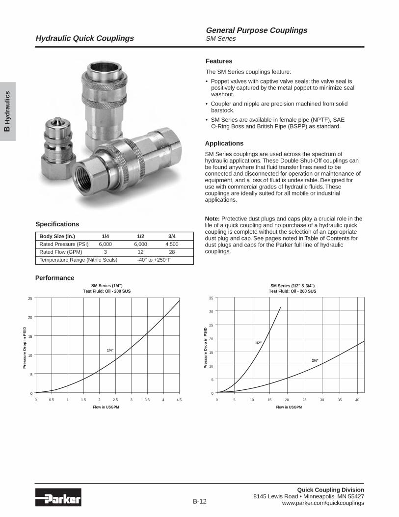
Features
The SM Series couplings feature:
• Poppet valves with captive valve seals: the valve seal ispositively captured by the metal poppet to minimize sealwashout.
• Coupler and nipple are precision machined from solidbarstock.
• SM Series are available in female pipe (NPTF), SAE O-Ring Boss and British Pipe (BSPP) as standard.
Applications
SM Series couplings are used across the spectrum ofhydraulic applications. These Double Shut-Off couplings canbe found anywhere that fluid transfer lines need to beconnected and disconnected for operation or maintenance ofequipment, and a loss of fluid is undesirable. Designed foruse with commercial grades of hydraulic fluids. Thesecouplings are ideally suited for all mobile or industrialapplications.
Note: Protective dust plugs and caps play a crucial role in thelife of a quick coupling and no purchase of a hydraulic quickcoupling is complete without the selection of an appropriatedust plug and cap. See pages noted in Table of Contents fordust plugs and caps for the Parker full line of hydrauliccouplings.
Specifications
Body Size (in.) 1/4 1/2 3/4
Rated Pressure (PSI) 6,000 6,000 4,500
Rated Flow (GPM) 3 12 28
Temperature Range (Nitrile Seals) -40° to +250°F
PerformanceSM Series (1/4")
Test Fluid: Oil - 200 SUS
0
5
10
15
20
25
0 0.5 1 1.5 2 2.5 3 3.5 4 4.5
Flow in USGPM
Pre
ssu
re D
rop
in
PS
ID
1/4"
SM Series (1/2" & 3/4")Test Fluid: Oil - 200 SUS
0
5
10
15
20
25
30
35
0 5 10 15 20 25 30 35 40
Flow in USGPM
Pre
ss
ure
Dro
p i
n P
SID
1/2"
3/4"
Quick Coupling Division8145 Lewis Road • Minneapolis, MN 55427
www.parker.com/quickcouplingsB-13
Hydraulic Quick Couplings
BH
ydra
ulic
s
General Purpose CouplingsSM Series
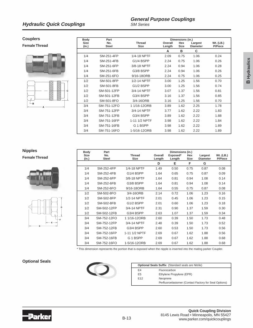
Couplers
Female Thread
Nipples
Female Thread
Optional Seals
C
B
A
G
F
E
D
Body Part Dimensions (in.)Size No. Thread Overall Hex Largest Wt. (LB.)(in.) Steel Size Length Size Diameter P/Piece
A B C
1/4 SM-251-4FP 1/4-18 NPTF 2.09 0.75 1.06 0.24
1/4 SM-251-4FB G1/4 BSPP 2.24 0.75 1.06 0.26
1/4 SM-251-6FP 3/8-18 NPTF 2.24 0.94 1.06 0.28
1/4 SM-251-6FB G3/8 BSPP 2.24 0.94 1.06 0.26
1/4 SM-251-6FO 9/16-18ORB 2.24 0.75 1.06 0.25
1/2 SM-501-8FP 1/2-14 NPTF 3.00 1.25 1.56 0.70
1/2 SM-501-8FB G1/2 BSPP 3.00 1.25 1.56 0.74
1/2 SM-501-12FP 3/4-14 NPTF 3.07 1.37 1.56 0.81
1/2 SM-501-12FB G3/4 BSPP 3.16 1.37 1.56 0.85
1/2 SM-501-8FO 3/4-16ORB 3.16 1.25 1.56 0.70
3/4 SM-751-12FO 1 1/16-12ORB 3.89 1.62 2.25 1.78
3/4 SM-751-12FP 3/4-14 NPTF 3.77 1.62 2.22 1.83
3/4 SM-751-12FB G3/4 BSPP 3.89 1.62 2.22 1.88
3/4 SM-751-16FP 1-11 1/2 NPTF 3.98 1.62 2.22 1.84
3/4 SM-751-16FB G 1 BSPP 3.98 1.62 2.22 1.89
3/4 SM-751-16FO 1-5/16-12ORB 3.98 1.62 2.22 1.89
Body Part Dimensions (in.)Size No. Thread Overall Exposed* Hex Largest Wt. (LB.)(in.) Steel Size Length Length Size Diameter P/Piece
D E F G
1/4 SM-252-4FP 1/4-18 NPTF 1.49 0.50 0.75 0.87 0.08
1/4 SM-252-4FB G1/4 BSPP 1.64 0.65 0.75 0.87 0.09
1/4 SM-252-6FP 3/8-18 NPTF 1.64 0.81 0.94 1.08 0.14
1/4 SM-252-6FB G3/8 BSPP 1.64 0.81 0.94 1.08 0.14
1/4 SM-252-6FO 9/16-18ORB 1.64 0.55 0.75 0.87 0.08
1/2 SM-502-8FO 3/4-16ORB 2.14 0.72 1.06 1.23 0.16
1/2 SM-502-8FP 1/2-14 NPTF 2.01 0.45 1.06 1.23 0.15
1/2 SM-502-8FB G1/2 BSPP 2.01 0.60 1.06 1.23 0.18
1/2 SM-502-12FP 3/4-14 NPTF 2.31 0.90 1.37 1.59 0.30
1/2 SM-502-12FB G3/4 BSPP 2.63 1.07 1.37 1.59 0.34
3/4 SM-752-12FO 1 1/16-12ORB 2.60 0.39 1.50 1.73 0.48
3/4 SM-752-12FP 3/4-14 NPTF 2.48 0.39 1.50 1.73 0.52
3/4 SM-752-12FB G3/4 BSPP 2.60 0.53 1.50 1.73 0.56
3/4 SM-752-16FP 1-11 1/2 NPTF 2.69 0.67 1.62 1.88 0.56
3/4 SM-752-16FB G 1 BSPP 2.69 0.67 1.62 1.88 0.68
3/4 SM-752-16FO 1-5/16-12ORB 2.69 0.67 1.62 1.88 0.68
* This dimension represents the portion that is exposed when the nipple is inserted into the mating parker Coupler.
Optional Seals Suffix (Standard seals are Nitrile)
E4 Fluorocarbon E5 Ethylene Propylene (EPR)E12 Neoprene
Perfluoroelastomer (Contact Factory for Seal Options)
Quick Coupling Division8145 Lewis Road • Minneapolis, MN 55427
www.parker.com/quickcouplingsB-14
Hydraulic Quick Couplings
BH
ydra
ulic
s
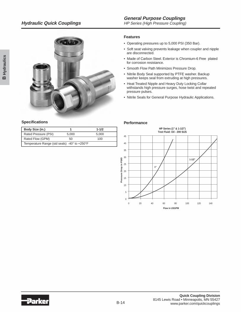
General Purpose CouplingsHP Series (High Pressure Coupling)
PerformanceHP Series (1" & 1-1/2")
Test Fluid: Oil - 200 SUS
0
5
10
15
20
25
30
35
40
45
0 20 40 60 80 100 120 140
Flow in USGPM
Pre
ssu
re D
rop
in
PS
ID
1"
1-1/2"
Specifications
Body Size (in.) 1 1-1/2
Rated Pressure (PSI) 5,000 5,000
Rated Flow (GPM) 50 100
Temperature Range (std seals) -40° to +250°F
Features
• Operating pressures up to 5,000 PSI (350 Bar).
• Soft seat valving prevents leakage when coupler and nippleare disconnected.
• Made of Carbon Steel. Exterior is Chromium-6 Free platedfor corrosion resistance.
• Smooth Flow Path Minimizes Pressure Drop.
• Nitrile Body Seal supported by PTFE washer. Backupwasher keeps seal from extruding at high pressures.
• Heat Treated Nipple and Heavy Duty Locking Collarwithstands high pressure surges, hose twist and repeatedpressure pulses.
• Nitrile Seals for General Purpose Hydraulic Applications.
Quick Coupling Division8145 Lewis Road • Minneapolis, MN 55427
www.parker.com/quickcouplingsB-15
Hydraulic Quick Couplings
BH
ydra
ulic
s
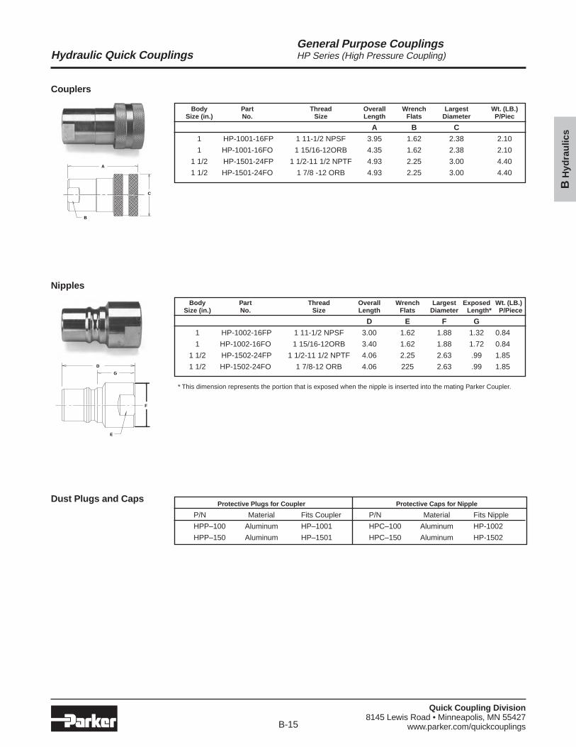
General Purpose CouplingsHP Series (High Pressure Coupling)
Couplers
Nipples
Dust Plugs and Caps
A
B
C
D
E
F
G
Body Part Thread Overall Wrench Largest Wt. (LB.)Size (in.) No. Size Length Flats Diameter P/Piec
A B C
1 HP-1001-16FP 1 11-1/2 NPSF 3.95 1.62 2.38 2.10
1 HP-1001-16FO 1 15/16-12ORB 4.35 1.62 2.38 2.10
1 1/2 HP-1501-24FP 1 1/2-11 1/2 NPTF 4.93 2.25 3.00 4.40
1 1/2 HP-1501-24FO 1 7/8 -12 ORB 4.93 2.25 3.00 4.40
Protective Plugs for Coupler Protective Caps for Nipple
P/N Material Fits Coupler P/N Material Fits Nipple
HPP–100 Aluminum HP–1001 HPC–100 Aluminum HP-1002
HPP–150 Aluminum HP–1501 HPC–150 Aluminum HP-1502
Body Part Thread Overall Wrench Largest Exposed Wt. (LB.)Size (in.) No. Size Length Flats Diameter Length* P/Piece
D E F G
1 HP-1002-16FP 1 11-1/2 NPSF 3.00 1.62 1.88 1.32 0.84
1 HP-1002-16FO 1 15/16-12ORB 3.40 1.62 1.88 1.72 0.84
1 1/2 HP-1502-24FP 1 1/2-11 1/2 NPTF 4.06 2.25 2.63 .99 1.85
1 1/2 HP-1502-24FO 1 7/8-12 ORB 4.06 225 2.63 .99 1.85
* This dimension represents the portion that is exposed when the nipple is inserted into the mating Parker Coupler.
Quick Coupling Division8145 Lewis Road • Minneapolis, MN 55427
www.parker.com/quickcouplingsB-16
Hydraulic Quick Couplings
BH
ydra
ulic
s
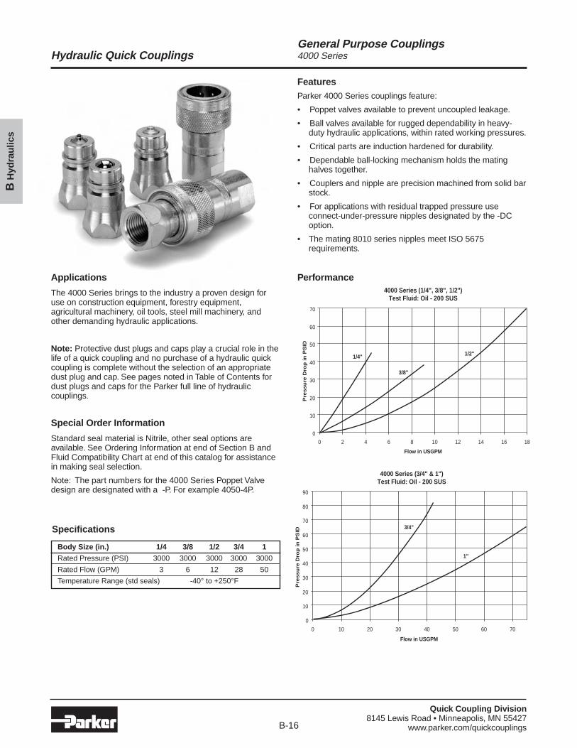
General Purpose Couplings4000 Series
FeaturesParker 4000 Series couplings feature:
• Poppet valves available to prevent uncoupled leakage.
• Ball valves available for rugged dependability in heavy-duty hydraulic applications, within rated working pressures.
• Critical parts are induction hardened for durability.
• Dependable ball-locking mechanism holds the matinghalves together.
• Couplers and nipple are precision machined from solid barstock.
• For applications with residual trapped pressure useconnect-under-pressure nipples designated by the -DCoption.
• The mating 8010 series nipples meet ISO 5675requirements.
Applications
The 4000 Series brings to the industry a proven design foruse on construction equipment, forestry equipment,agricultural machinery, oil tools, steel mill machinery, andother demanding hydraulic applications.
Note: Protective dust plugs and caps play a crucial role in thelife of a quick coupling and no purchase of a hydraulic quickcoupling is complete without the selection of an appropriatedust plug and cap. See pages noted in Table of Contents fordust plugs and caps for the Parker full line of hydrauliccouplings.
Special Order Information
Standard seal material is Nitrile, other seal options areavailable. See Ordering Information at end of Section B andFluid Compatibility Chart at end of this catalog for assistancein making seal selection.
Note: The part numbers for the 4000 Series Poppet Valvedesign are designated with a -P. For example 4050-4P.
Performance4000 Series (1/4", 3/8", 1/2")
Test Fluid: Oil - 200 SUS
0
10
20
30
40
50
60
70
0 2 4 6 8 10 12 14 16 18
Flow in USGPM
Pre
ssu
re D
rop
in
PS
ID
1/4"
3/8"
1/2"
Specifications
Body Size (in.) 1/4 3/8 1/2 3/4 1
Rated Pressure (PSI) 3000 3000 3000 3000 3000
Rated Flow (GPM) 3 6 12 28 50
Temperature Range (std seals) -40° to +250°F
4000 Series (3/4" & 1")Test Fluid: Oil - 200 SUS
0
10
20
30
40
50
60
70
80
90
0 10 20 30 40 50 60 70
Flow in USGPM
Pre
ssu
re D
rop
in
PS
ID
3/4"
1"
Quick Coupling Division8145 Lewis Road • Minneapolis, MN 55427
www.parker.com/quickcouplingsB-17
Hydraulic Quick Couplings
BH
ydra
ulic
s
General Purpose Couplings4000 Series
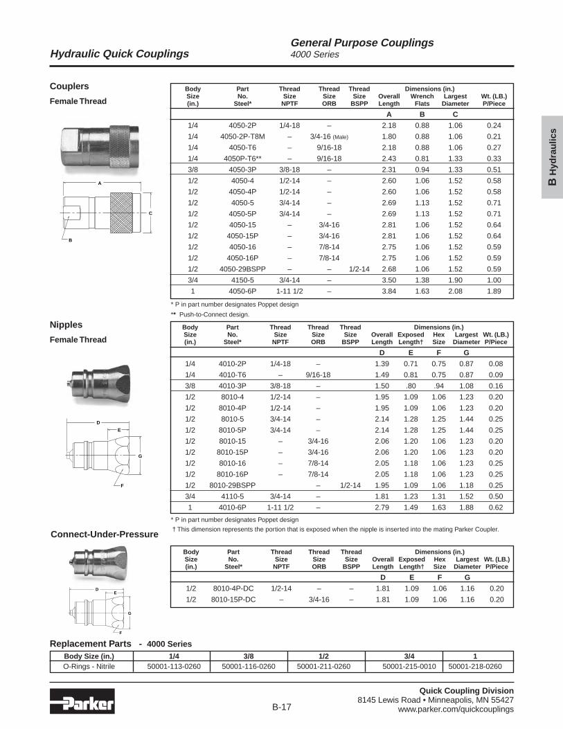
Nipples
Female Thread
Couplers
Female Thread
A
C
B
E
D
F
G
Body Part Thread Thread Thread Dimensions (in.)Size No. Size Size Size Overall Exposed Hex Largest Wt. (LB.)(in.) Steel* NPTF ORB BSPP Length Length† Size Diameter P/Piece
D E F G
1/4 4010-2P 1/4-18 – 1.39 0.71 0.75 0.87 0.08
1/4 4010-T6 – 9/16-18 1.49 0.81 0.75 0.87 0.09
3/8 4010-3P 3/8-18 – 1.50 .80 .94 1.08 0.16
1/2 8010-4 1/2-14 – 1.95 1.09 1.06 1.23 0.20
1/2 8010-4P 1/2-14 – 1.95 1.09 1.06 1.23 0.20
1/2 8010-5 3/4-14 – 2.14 1.28 1.25 1.44 0.25
1/2 8010-5P 3/4-14 – 2.14 1.28 1.25 1.44 0.25
1/2 8010-15 – 3/4-16 2.06 1.20 1.06 1.23 0.20
1/2 8010-15P – 3/4-16 2.06 1.20 1.06 1.23 0.20
1/2 8010-16 – 7/8-14 2.05 1.18 1.06 1.23 0.25
1/2 8010-16P – 7/8-14 2.05 1.18 1.06 1.23 0.25
1/2 8010-29BSPP – 1/2-14 1.95 1.09 1.06 1.18 0.25
3/4 4110-5 3/4-14 – 1.81 1.23 1.31 1.52 0.50
1 4010-6P 1-11 1/2 – 2.79 1.49 1.63 1.88 0.62
* P in part number designates Poppet design
Replacement Parts - 4000 SeriesBody Size (in.) 1/4 3/8 1/2 3/4 1O-Rings - Nitrile 50001-113-0260 50001-116-0260 50001-211-0260 50001-215-0010 50001-218-0260
Body Part Thread Thread Thread Dimensions (in.)Size No. Size Size Size Overall Wrench Largest Wt. (LB.)(in.) Steel* NPTF ORB BSPP Length Flats Diameter P/Piece
A B C
1/4 4050-2P 1/4-18 – 2.18 0.88 1.06 0.24
1/4 4050-2P-T8M – 3/4-16 (Male) 1.80 0.88 1.06 0.21
1/4 4050-T6 – 9/16-18 2.18 0.88 1.06 0.27
1/4 4050P-T6** – 9/16-18 2.43 0.81 1.33 0.33
3/8 4050-3P 3/8-18 – 2.31 0.94 1.33 0.51
1/2 4050-4 1/2-14 – 2.60 1.06 1.52 0.58
1/2 4050-4P 1/2-14 – 2.60 1.06 1.52 0.58
1/2 4050-5 3/4-14 – 2.69 1.13 1.52 0.71
1/2 4050-5P 3/4-14 – 2.69 1.13 1.52 0.71
1/2 4050-15 – 3/4-16 2.81 1.06 1.52 0.64
1/2 4050-15P – 3/4-16 2.81 1.06 1.52 0.64
1/2 4050-16 – 7/8-14 2.75 1.06 1.52 0.59
1/2 4050-16P – 7/8-14 2.75 1.06 1.52 0.59
1/2 4050-29BSPP – – 1/2-14 2.68 1.06 1.52 0.59
3/4 4150-5 3/4-14 – 3.50 1.38 1.90 1.00
1 4050-6P 1-11 1/2 – 3.84 1.63 2.08 1.89
* P in part number designates Poppet design
** Push-to-Connect design.
† This dimension represents the portion that is exposed when the nipple is inserted into the mating Parker Coupler.Connect-Under-Pressure
ED
F
G
Body Part Thread Thread Thread Dimensions (in.)Size No. Size Size Size Overall Exposed Hex Largest Wt. (LB.)(in.) Steel* NPTF ORB BSPP Length Length† Size Diameter P/Piece
D E F G
1/2 8010-4P-DC 1/2-14 – – 1.81 1.09 1.06 1.16 0.20
1/2 8010-15P-DC – 3/4-16 – 1.81 1.09 1.06 1.16 0.20
Quick Coupling Division8145 Lewis Road • Minneapolis, MN 55427
www.parker.com/quickcouplingsB-18
Hydraulic Quick Couplings
BH
ydra
ulic
s
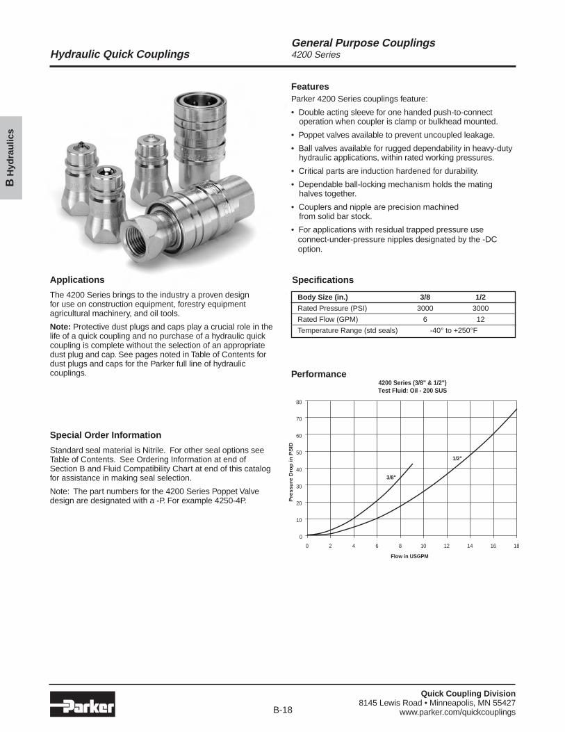
General Purpose Couplings4200 Series
FeaturesParker 4200 Series couplings feature:
• Double acting sleeve for one handed push-to-connectoperation when coupler is clamp or bulkhead mounted.
• Poppet valves available to prevent uncoupled leakage.
• Ball valves available for rugged dependability in heavy-dutyhydraulic applications, within rated working pressures.
• Critical parts are induction hardened for durability.
• Dependable ball-locking mechanism holds the matinghalves together.
• Couplers and nipple are precision machined from solid bar stock.
• For applications with residual trapped pressure useconnect-under-pressure nipples designated by the -DCoption.
Applications
The 4200 Series brings to the industry a proven design for use on construction equipment, forestry equipmentagricultural machinery, and oil tools.
Note: Protective dust plugs and caps play a crucial role in thelife of a quick coupling and no purchase of a hydraulic quickcoupling is complete without the selection of an appropriatedust plug and cap. See pages noted in Table of Contents fordust plugs and caps for the Parker full line of hydrauliccouplings.
Special Order Information
Standard seal material is Nitrile. For other seal options seeTable of Contents. See Ordering Information at end ofSection B and Fluid Compatibility Chart at end of this catalogfor assistance in making seal selection.
Note: The part numbers for the 4200 Series Poppet Valvedesign are designated with a -P. For example 4250-4P.
Performance4200 Series (3/8" & 1/2")Test Fluid: Oil - 200 SUS
0
10
20
30
40
50
60
70
80
0 2 4 6 8 10 12 14 16 18
Flow in USGPM
Pre
ssu
re D
rop
in
PS
ID
3/8"
1/2"
Specifications
Body Size (in.) 3/8 1/2
Rated Pressure (PSI) 3000 3000
Rated Flow (GPM) 6 12
Temperature Range (std seals) -40° to +250°F
Quick Coupling Division8145 Lewis Road • Minneapolis, MN 55427
www.parker.com/quickcouplingsB-19
Hydraulic Quick Couplings
BH
ydra
ulic
s
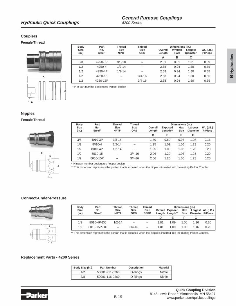
General Purpose Couplings4200 Series
Nipples
Female Thread
Couplers
Female Thread
E
D
F
G
Replacement Parts - 4200 Series
Body Size (in.) Part Number Description Material
1/2 50001-211-0260 O-Rings Nitrile
3/8 50001-116-0260 O-Rings Nitrile
A
C
B
Body Part Thread Thread Dimensions (in.)Size No. Size Size Overall Exposed Hex Largest Wt. (LB.)(in.) Steel* NPTF ORB Length Length** Size Diameter P/Piece
D E F G
3/8 4010-3P 3/8-18 – 1.60 0.80 0.94 1.08 0.16
1/2 8010-4 1/2-14 – 1.95 1.09 1.06 1.23 0.20
1/2 8010-4P 1/2-14 – 1.95 1.09 1.06 1.23 0.20
1/2 8010-15 – 3/4-16 2.06 1.20 1.06 1.23 0.20
1/2 8010-15P – 3/4-16 2.06 1.20 1.06 1.23 0.20
Body Part Thread Thread Dimensions (in.)Size No. Size Size Overall Wrench Largest Wt. (LB.)(in.) Steel* NPTF ORB Length Flats Diameter P/Piece
A B C
3/8 4250-3P 3/8-18 – 2.31 0.81 1.31 0.39
1/2 4250-4 1/2-14 – 2.68 0.94 1.50 0.55
1/2 4250-4P 1/2-14 – 2.68 0.94 1.50 0.55
1/2 4250-15 – 3/4-16 2.68 0.94 1.50 0.55
1/2 4250-15P – 3/4-16 2.68 0.94 1.50 0.55
* P in part number designates Poppet design
* P in part number designates Poppet design** This dimension represents the portion that is exposed when the nipple is inserted into the mating Parker Coupler.
Connect-Under-Pressure
ED
F
G
Body Part Thread Thread Thread Dimensions (in.)Size No. Size Size Size Overall Exposed Hex Largest Wt. (LB.)(in.) Steel* NPTF ORB BSPP Length Length** Size Diameter P/Piece
D E F G
1/2 8010-4P-DC 1/2-14 – – 1.81 1.09 1.06 1.16 0.20
1/2 8010-15P-DC – 3/4-16 – 1.81 1.09 1.06 1.16 0.20
** This dimension represents the portion that is exposed when the nipple is inserted into the mating Parker Coupler.

Continue to next section for more
information


