Hydraulics Troubleshooting January 2019 Hydraulic Power Units When there is a problem with a KTI Power Unit; from the pump tag we need the Model, Serial Number, Date and the last 6 digits of the trailer VIN#. An option is to contact KTI directly at 714-556-8818. Reservoir overflowing Low Battery, loose Hydrauilc Lines or Loose Inlet: the most common cause is low battery charge or poor ground condition. Solenoid The Starter Solenoid is not covered under warranty since its condition is directly related to the battery charge level. Using an under-charged battery causes a high amp draw that will make the contacts stick and burn up the starter solenoid. Bed not going up or down Causes include a failed solenoid, poor electrical connection between the control and the pump, or loose wiring in the remote itself. If the pump is running but doesn’t affect the hydraulics, it may be a stuck valve. If when the pump works in one direction but not the other, try swapping the coils to see if it will work in the opposite direction. If this is the case; you will have a faulty coil. www.diamondc.com 800.827.3512 Contact: Keith Barnes Warranty Service Manager [email protected]@diamondctrailers
Transcript
Hydraulics Troubleshooting
January 2019
Hydraulic Power Units
When there is a problem with a KTI Power Unit; from the pump tag we need the Model, Serial Number, Date and the last 6 digits of the trailer VIN#. An option is to contact KTI directly at 714-556-8818.
Reservoir overflowing
Low Battery, loose Hydrauilc Lines or Loose Inlet: the most common cause is low battery charge or poor ground condition.
Solenoid
The Starter Solenoid is not covered under warranty since its condition is directly related to the battery charge level. Using an under-charged battery causes a high amp draw that will make the contacts stick and burn up the starter solenoid.
Bed not going up or down
Causes include a failed solenoid, poor electrical connection between the control and the pump, or loose wiring in the remote itself. If the pump is running but doesn’t affect the hydraulics, it may be a stuck valve. If when the pump works in one direction but not the other, try swapping the coils to see if it will work in the opposite direction. If this is the case; you will have a faulty coil.
The purpose of this guide is to help you trouble shoot KTI DC Hydraulic Power Units, by explaining how the electric & hydraulic circuits work together to perform each function. Also included are some tricks & tips we have found talking to you the customer. This guide will help you fix the majority of problems you face in the field. If you run into an issue not explained please let us know, our service staff will be more than willing to help solve your issue
Warranty KTI Hydraulics Inc, Warranties its products free from defects in material, workmanship & design for a period of 2 years from the date of manufacture on DC Units & 1 year from date of manufacture on AC Units. Under no circumstances is there warranty of fitness for a particular use and KTI Hydraulics Inc. cannot and does not accept responsibilities of any of its products that have subject to improper installation, improper application, negligence tampering or abuse. All repairs must be authorized by factory to reduce the risk of voiding warranty. KTI Hydraulics liability warranty shall extend only to correction F.O.B KTI Hydraulics Inc. We make no other warranties expressed or implied and are not responsible for any damage resulting from use by any buyer or user, our liability being limited to the value of the product sold, or obligated to repair or replace defective part. For warranty information or warranty request please contact Customer Service. Power Units without Model Number & Serial Number will not be covered under warranty, when calling please have model number & Serial Number ready. Any information & symptoms of issue will help us with your issue.
3
2621 South Daimler St.
Santa Ana, CA. 92705
Tel. 949.752.8818 x Fax 949.756.1520
w w w . k t i h y d r a u l i c s i n c . c o m
Not Covered Under Warranty KTI Hydraulics cannot and does not accept responsibilities of any type or any of its products that have been subjected to improper installation, improper application, negligence, tampering or abuse. The Following are reasons why KTI does not cover under warranty:
1.) Improper Installation- Such as over torque of mounting bolts during installs resulting in damage to Power Unit. KTI cannot and does not accept responsibilities for damage to its product under such circumstances.
2.) Improper Application- KTI cannot and does not accept responsibility for any units that have been improperly spec out due to lack of information about that particular application. Example; if an application requires water sealed motor and it is not specified about to what elements unit will be exposed to. KTI cannot and does not accept responsibilities for motor failure due to corrosion or rust. KTI relies on customer to provide all information relating to the application such as its exposure or enclosure as to where unit will be mounted.
3.) Negligence- KTI will not take responsibility for any product neglected by customer. Such as customer leaves box to trailer open and unit gets wet resulting in failure of motor or valves due to the corrosion or rust, Customer neglected to service on unit resulting in sever contamination to unit.
4.) Tampering- Units tampered with and or revised other than factory assessment will not be considered for warranty. All relief valves are factory pre-set. Any adjusting or tampering can result in severe injury or even death. Units adjusted in field can result in burning up of solenoids, motors and coils in which KTI does not take responsibility for. Any adjustments in field must be approved by KTI via written email / Fax.
5.) Abuse- KTI stands behind their products one hundred percent. All products are tested before
shipping. Any abuse to products will not be considered for warranty. The following are considered abuse per KTI.
x Low Voltage / battery- Causes high amp draw. High amps can burn up electrical
components such as start solenoids, coils, motors, and contacts in hand controls. x Contamination – Contamination in the system can cause valve failure and pump failure.
It can also lead to cylinder failure as well. x Rust – Water in fluid can cause valves to rust resulting in failure such as hanging up of
valve spool, corrosion and seizure of pump, and/or motor. x Improper Fluid – Can cause failure of pump and motor. The wrong viscosity grade can
cause pump to struggle resulting in bogging down of motor which can result in high amp draw of unit. High Amp draw can result in burning up of Motor and other components.
4
2621 South Daimler St.
Santa Ana, CA. 92705
Tel. 949.752.8818 x Fax 949.756.1520
w w w . k t i h y d r a u l i c s i n c . c o m
Warning
When working on a Hydraulic System Always Insure Hydraulic Lines have been depressurized. Hydraulic Injection can cause loss of fingers & even
loss of Life in severe cases. Hydraulic Injection can seem like a Bee Sting. If you are ever bitten by Hydraulic Injection go directly to the Emergency Room for Treatment.
For more information on Hydraulic Injection contact:
Fluid Power Training Institute www.fpti.org
Introduction to Troubleshooting Hydraulic Power Units When troubleshooting Hydraulic Power Units you first want to understand how the hydraulic circuit works with the electrical circuit, Also the sequence of operation for each hydraulic circuit. If you can understand these two things you can fix most hydraulic systems.
Most problems with mobile Hydraulic Power Units are electrical, the most common being poor ground condition which will simulate low battery. Always insure your battery is getting charged. If you are using your hydraulic system frequently you may need to place the battery on charge more frequently.
Never adjust relief valves unless consulting factory. Relief valves are factory preset to the manufacturer’s specification. Adjusting the relief valve will not help the power unit build pressure. The last thing you want to do is adjust the relief valve. Tampering with relief valve could cause injury, catastrophic failure resulting in death. Having a designated auxiliary battery for your hydraulic system is recommended. Always place a fuse or circuit breaker in charge wire to auxiliary battery. If your battery gets low the Fuse or circuit breaker will blow, if this happens reference battery section in Guide (Page 8). After you have ruled out the electrical circuit use the Quick Reference Chart to solve your issue. Having a 5000 psi Pressure Gage, Flow Meter & Extra Fitting to Tee in the Pressure Gages will make your job a lot easier.
5
2621 South Daimler St.
Santa Ana, CA. 92705
Tel. 949.752.8818 x Fax 949.756.1520
w w w . k t i h y d r a u l i c s i n c . c o m
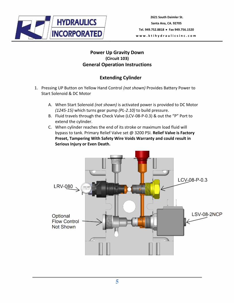
Power Up Gravity Down
(Circuit 103) General Operation Instructions
Extending Cylinder
1. Pressing UP Button on Yellow Hand Control (not shown) Provides Battery Power to Start Solenoid & DC Motor
A. When Start Solenoid (not shown) is activated power is provided to DC Motor
(1245-15) which turns gear pump (PL-2.10) to build pressure. B. Fluid travels through the Check Valve (LCV-08-P-0.3) & out the “P” Port to
extend the cylinder. C. When cylinder reaches the end of its stroke or maximum load fluid will
bypass to tank. Primary Relief Valve set @ 3200 PSI. Relief Valve is Factory Preset, Tampering With Safety Wire Voids Warranty and could result in Serious Injury or Even Death.
6
2621 South Daimler St.
Santa Ana, CA. 92705
Tel. 949.752.8818 x Fax 949.756.1520
w w w . k t i h y d r a u l i c s i n c . c o m
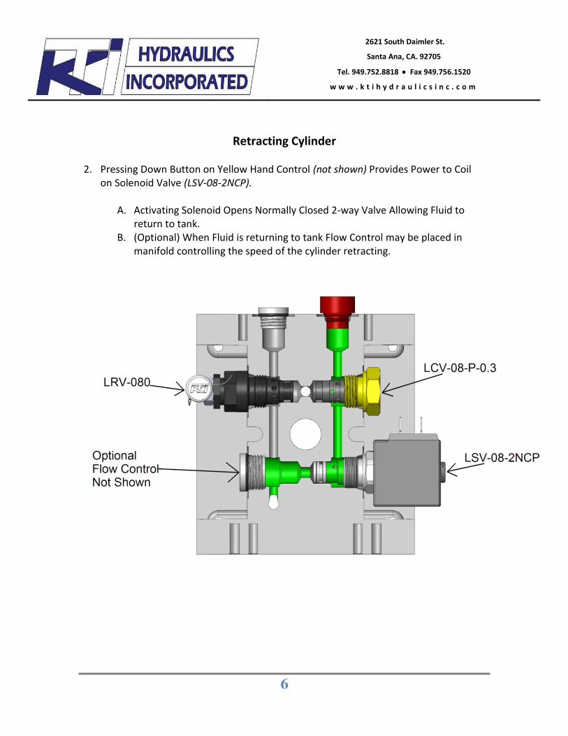
Retracting Cylinder 2. Pressing Down Button on Yellow Hand Control (not shown) Provides Power to Coil
on Solenoid Valve (LSV-08-2NCP).
A. Activating Solenoid Opens Normally Closed 2-way Valve Allowing Fluid to return to tank.
B. (Optional) When Fluid is returning to tank Flow Control may be placed in manifold controlling the speed of the cylinder retracting.
7
2621 South Daimler St.
Santa Ana, CA. 92705
Tel. 949.752.8818 x Fax 949.756.1520
w w w . k t i h y d r a u l i c s i n c . c o m
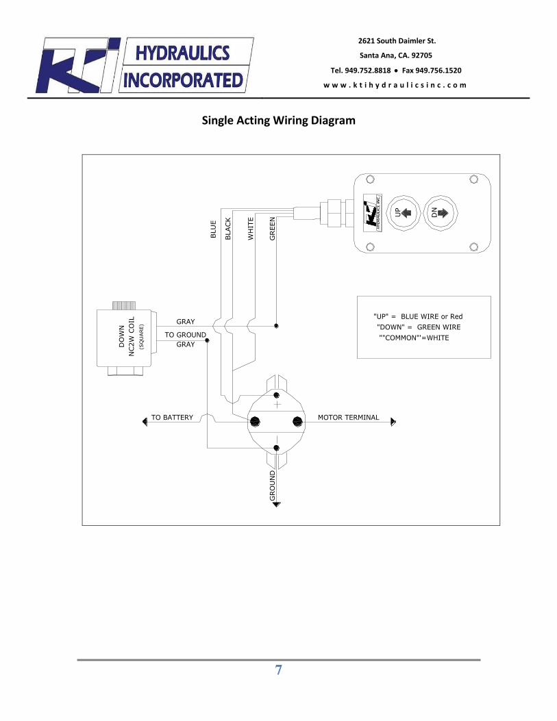
Single Acting Wiring Diagram
MOTOR TERMINAL
GRO
UN
D
TO BATTERY
GREE
N
BLA
CK
BLU
E
WH
ITE
TO GROUND
GRAY
""COMMON"'=WHITE
"UP" = BLUE WIRE or Red"DOWN" = GREEN WIRE
DN
UP
GRAY
NC2W
CO
ILD
OW
N
(SQ
UARE)
8
2621 South Daimler St.
Santa Ana, CA. 92705
Tel. 949.752.8818 x Fax 949.756.1520
w w w . k t i h y d r a u l i c s i n c . c o m
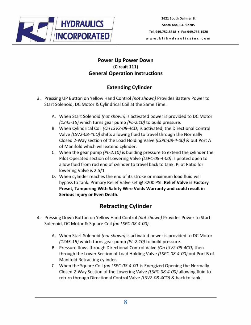
Power Up Power Down (Circuit 111)
General Operation Instructions
Extending Cylinder
3. Pressing UP Button on Yellow Hand Control (not shown) Provides Battery Power to Start Solenoid, DC Motor & Cylindrical Coil at the Same Time.
A. When Start Solenoid (not shown) is activated power is provided to DC Motor
(1245-15) which turns gear pump (PL-2.10) to build pressure. B. When Cylindrical Coil (On LSV2-08-4CO) is activated, the Directional Control
Valve (LSV2-08-4CO) shifts allowing fluid to travel through the Normally Closed 2-Way section of the Load Holding Valve (LSPC-08-4-00) & out Port A of Manifold which will extend cylinder.
C. When the gear pump (PL-2.10) is building pressure to extend the cylinder the Pilot Operated section of Lowering Valve (LSPC-08-4-00) is piloted open to allow fluid from rod end of cylinder to travel back to tank. Pilot Ratio for lowering Valve is 2.5/1
D. When cylinder reaches the end of its stroke or maximum load fluid will bypass to tank. Primary Relief Valve set @ 3200 PSI. Relief Valve is Factory Preset, Tampering With Safety Wire Voids Warranty and could result in Serious Injury or Even Death.
Retracting Cylinder
4. Pressing Down Button on Yellow Hand Control (not shown) Provides Power to Start Solenoid, DC Motor & Square Coil (on LSPC-08-4-00).
A. When Start Solenoid (not shown) is activated power is provided to DC Motor
(1245-15) which turns gear pump (PL-2.10) to build pressure. B. Pressure flows through Directional Control Valve (On LSV2-08-4CO) then
through the Lower Section of Load Holding Valve (LSPC-08-4-00) out Port B of Manifold Retracting cylinder.
C. When the Square Coil (on LSPC-08-4-00 is Energized Opening the Normally Closed 2-Way Section of the Lowering Valve (LSPC-08-4-00) allowing fluid to return through Directional Control Valve (LSV2-08-4CO) & back to tank.
9
2621 South Daimler St.
Santa Ana, CA. 92705
Tel. 949.752.8818 x Fax 949.756.1520
w w w . k t i h y d r a u l i c s i n c . c o m
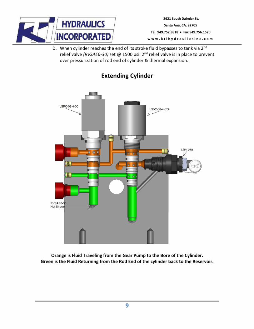
D. When cylinder reaches the end of its stroke fluid bypasses to tank via 2nd relief valve (RVSAE6-30) set @ 1500 psi. 2nd relief valve is in place to prevent over pressurization of rod end of cylinder & thermal expansion.
Extending Cylinder
Orange is Fluid Traveling from the Gear Pump to the Bore of the Cylinder. Green is the Fluid Returning from the Rod End of the cylinder back to the Reservoir.
10
2621 South Daimler St.
Santa Ana, CA. 92705
Tel. 949.752.8818 x Fax 949.756.1520
w w w . k t i h y d r a u l i c s i n c . c o m
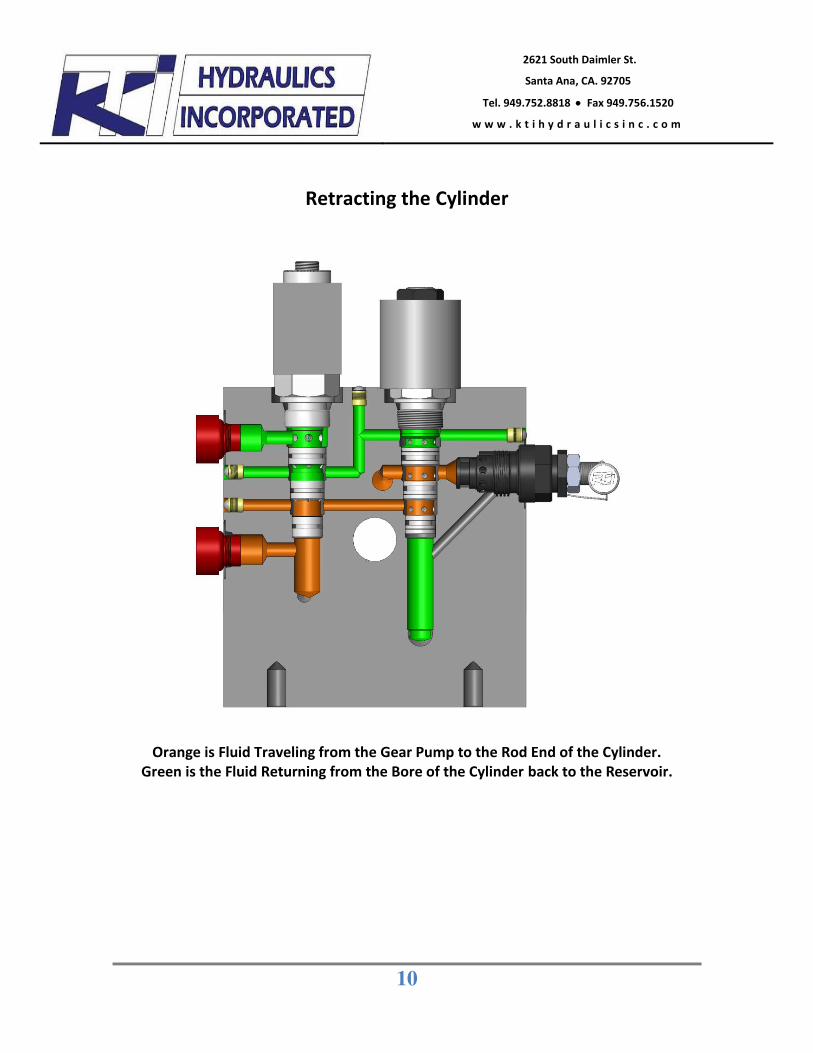
Retracting the Cylinder
Orange is Fluid Traveling from the Gear Pump to the Rod End of the Cylinder. Green is the Fluid Returning from the Bore of the Cylinder back to the Reservoir.
11
2621 South Daimler St.
Santa Ana, CA. 92705
Tel. 949.752.8818 x Fax 949.756.1520
w w w . k t i h y d r a u l i c s i n c . c o m
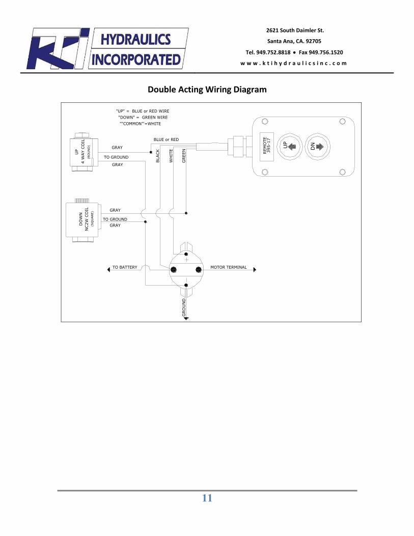
Double Acting Wiring Diagram
MOTOR TERMINAL
WH
ITE
GREE
N
BLA
CK
TO BATTERY
GRAY
GRAY
TO GROUND
GRAY
GRO
UN
D
""COMMON"'=WHITE
"UP" = BLUE or RED WIRE"DOWN" = GREEN WIRE
GRAY
BLUE or RED
REM
OTE
395-
17
DNUP
UP
4 W
AY
CO
ILD
OW
NN
C2W
CO
IL(R
OU
ND
)(S
QU
ARE)
12
2621 South Daimler St.
Santa Ana, CA. 92705
Tel. 949.752.8818 x Fax 949.756.1520
w w w . k t i h y d r a u l i c s i n c . c o m
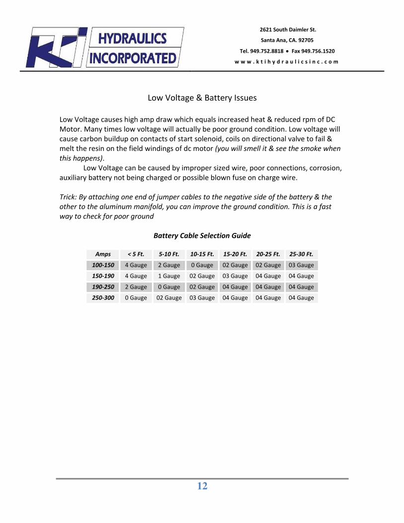
Low Voltage & Battery Issues
Low Voltage causes high amp draw which equals increased heat & reduced rpm of DC Motor. Many times low voltage will actually be poor ground condition. Low voltage will cause carbon buildup on contacts of start solenoid, coils on directional valve to fail & melt the resin on the field windings of dc motor (you will smell it & see the smoke when this happens). Low Voltage can be caused by improper sized wire, poor connections, corrosion, auxiliary battery not being charged or possible blown fuse on charge wire. Trick: By attaching one end of jumper cables to the negative side of the battery & the other to the aluminum manifold, you can improve the ground condition. This is a fast way to check for poor ground
Battery Cable Selection Guide
Amps < 5 Ft. 5-10 Ft. 10-15 Ft. 15-20 Ft. 20-25 Ft. 25-30 Ft. 100-150 4 Gauge 2 Gauge 0 Gauge 02 Gauge 02 Gauge 03 Gauge
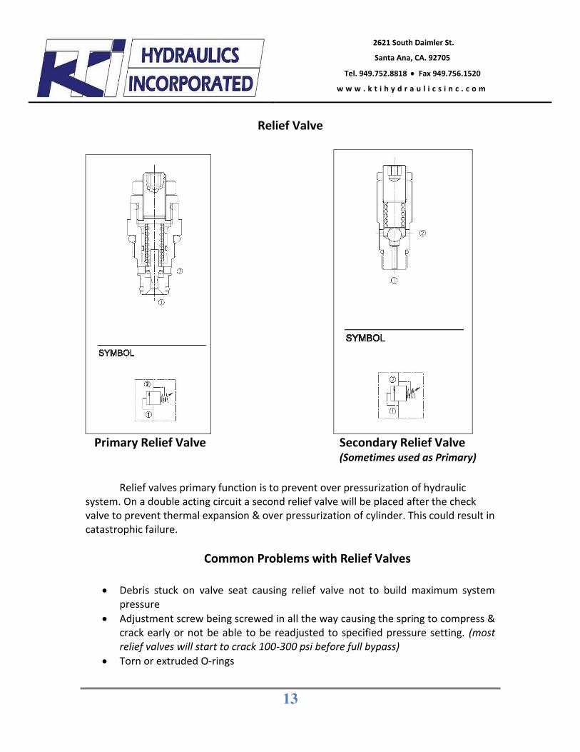
Primary Relief Valve Secondary Relief Valve (Sometimes used as Primary)
Relief valves primary function is to prevent over pressurization of hydraulic system. On a double acting circuit a second relief valve will be placed after the check valve to prevent thermal expansion & over pressurization of cylinder. This could result in catastrophic failure.
Common Problems with Relief Valves
x Debris stuck on valve seat causing relief valve not to build maximum system
pressure x Adjustment screw being screwed in all the way causing the spring to compress &
crack early or not be able to be readjusted to specified pressure setting. (most relief valves will start to crack 100-300 psi before full bypass)
x Torn or extruded O-rings
14
2621 South Daimler St.
Santa Ana, CA. 92705
Tel. 949.752.8818 x Fax 949.756.1520
w w w . k t i h y d r a u l i c s i n c . c o m
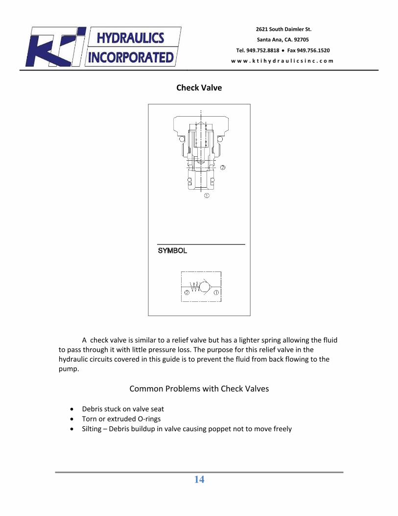
Check Valve
A check valve is similar to a relief valve but has a lighter spring allowing the fluid to pass through it with little pressure loss. The purpose for this relief valve in the hydraulic circuits covered in this guide is to prevent the fluid from back flowing to the pump.
Common Problems with Check Valves x Debris stuck on valve seat x Torn or extruded O-rings x Silting – Debris buildup in valve causing poppet not to move freely
15
2621 South Daimler St.
Santa Ana, CA. 92705
Tel. 949.752.8818 x Fax 949.756.1520
w w w . k t i h y d r a u l i c s i n c . c o m
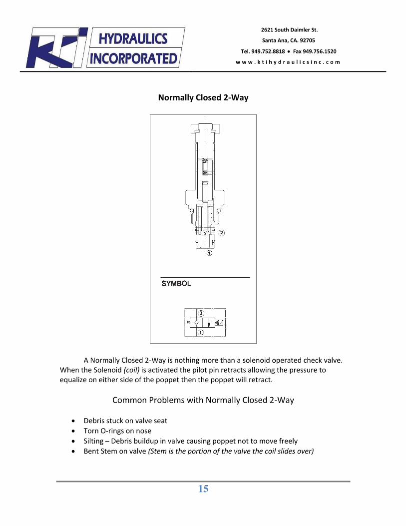
Normally Closed 2-Way
A Normally Closed 2-Way is nothing more than a solenoid operated check valve. When the Solenoid (coil) is activated the pilot pin retracts allowing the pressure to equalize on either side of the poppet then the poppet will retract.
Common Problems with Normally Closed 2-Way
x Debris stuck on valve seat x Torn O-rings on nose x Silting – Debris buildup in valve causing poppet not to move freely x Bent Stem on valve (Stem is the portion of the valve the coil slides over)
16
2621 South Daimler St.
Santa Ana, CA. 92705
Tel. 949.752.8818 x Fax 949.756.1520
w w w . k t i h y d r a u l i c s i n c . c o m
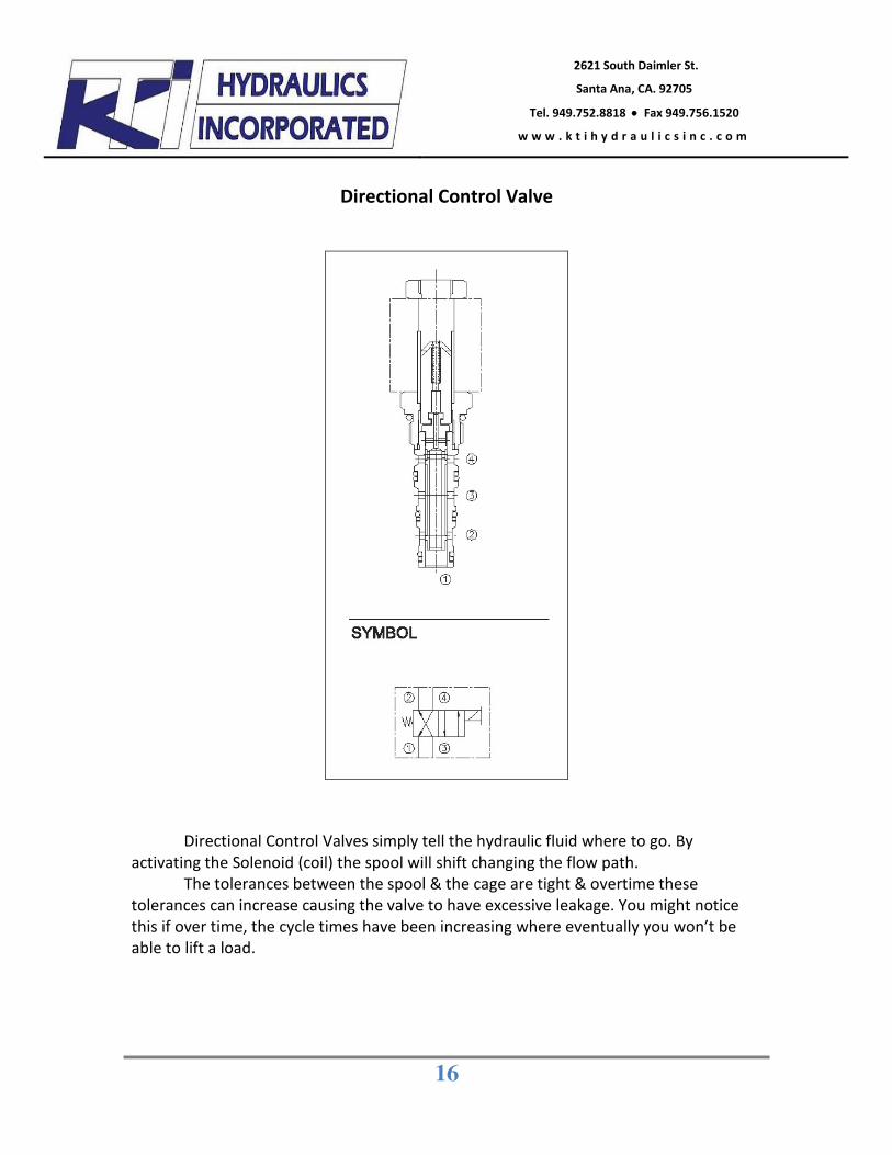
Directional Control Valve
Directional Control Valves simply tell the hydraulic fluid where to go. By activating the Solenoid (coil) the spool will shift changing the flow path.
The tolerances between the spool & the cage are tight & overtime these tolerances can increase causing the valve to have excessive leakage. You might notice this if over time, the cycle times have been increasing where eventually you won’t be able to lift a load.
17
2621 South Daimler St.
Santa Ana, CA. 92705
Tel. 949.752.8818 x Fax 949.756.1520
w w w . k t i h y d r a u l i c s i n c . c o m
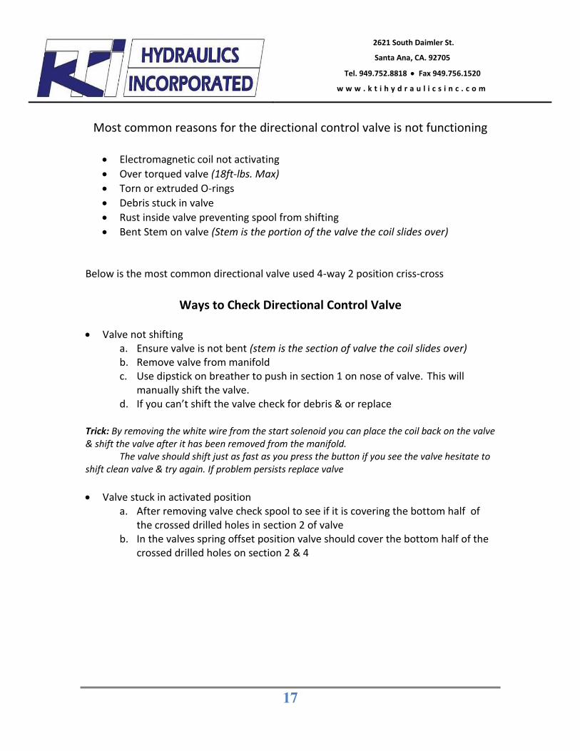
Most common reasons for the directional control valve is not functioning
x Electromagnetic coil not activating x Over torqued valve (18ft-lbs. Max) x Torn or extruded O-rings x Debris stuck in valve x Rust inside valve preventing spool from shifting x Bent Stem on valve (Stem is the portion of the valve the coil slides over)
Below is the most common directional valve used 4-way 2 position criss-cross
Ways to Check Directional Control Valve
x Valve not shifting
a. Ensure valve is not bent (stem is the section of valve the coil slides over) b. Remove valve from manifold c. Use dipstick on breather to push in section 1 on nose of valve. This will
manually shift the valve. d. If you can’t shift the valve check for debris & or replace
Trick: By removing the white wire from the start solenoid you can place the coil back on the valve & shift the valve after it has been removed from the manifold. The valve should shift just as fast as you press the button if you see the valve hesitate to shift clean valve & try again. If problem persists replace valve x Valve stuck in activated position
a. After removing valve check spool to see if it is covering the bottom half of the crossed drilled holes in section 2 of valve
b. In the valves spring offset position valve should cover the bottom half of the crossed drilled holes on section 2 & 4
18
2621 South Daimler St.
Santa Ana, CA. 92705
Tel. 949.752.8818 x Fax 949.756.1520
w w w . k t i h y d r a u l i c s i n c . c o m
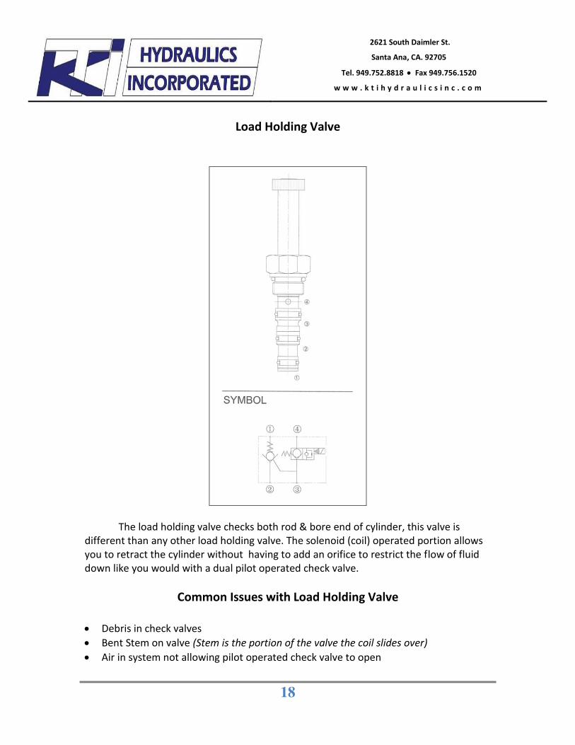
Load Holding Valve
The load holding valve checks both rod & bore end of cylinder, this valve is different than any other load holding valve. The solenoid (coil) operated portion allows you to retract the cylinder without having to add an orifice to restrict the flow of fluid down like you would with a dual pilot operated check valve.
Common Issues with Load Holding Valve
x Debris in check valves x Bent Stem on valve (Stem is the portion of the valve the coil slides over) x Air in system not allowing pilot operated check valve to open
19
2621 South Daimler St.
Santa Ana, CA. 92705
Tel. 949.752.8818 x Fax 949.756.1520
w w w . k t i h y d r a u l i c s i n c . c o m
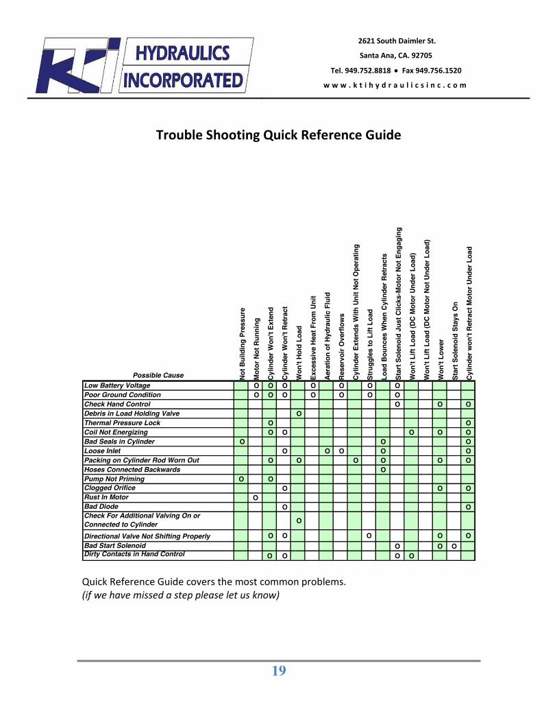
Trouble Shooting Quick Reference Guide
Possible Cause Not B
uild
ing
Pres
sure
Mot
or N
ot R
unni
ng
Cylin
der W
on't
Exte
nd
Cylin
der W
on't
Retra
ct
Won
't Ho
ld L
oad
Exce
ssiv
e He
at F
rom
Uni
t
Aera
tion
of H
ydra
ulic
Flu
id
Rese
rvoi
r Ove
rflow
s
Cylin
der E
xten
ds W
ith U
nit N
ot O
pera
ting
Stru
ggle
s to
Lift
Loa
d
Load
Bou
nces
Whe
n Cy
linde
r Ret
ract
s
Star
t Sol
enoi
d Ju
st C
licks
-Mot
or N
ot E
ngag
ing
Won
't Li
ft Lo
ad (D
C M
otor
Und
er L
oad)
Won
't Li
ft Lo
ad (D
C M
otor
Not
Und
er L
oad)
Won
't Lo
wer
Star
t Sol
enoi
d St
ays
On
Cylin
der w
on't
Retra
ct M
otor
Und
er L
oad
Low Battery Voltage O O O O O O OPoor Ground Condition O O O O O O OCheck Hand Control O O ODebris in Load Holding Valve OThermal Pressure Lock O OCoil Not Energizing O O O O OBad Seals in Cylinder O O OLoose Inlet O O O O OPacking on Cylinder Rod Worn Out O O O O O OHoses Connected Backwards OPump Not Priming O OClogged Orifice O O ORust In Motor OBad Diode O OCheck For Additional Valving On or Connected to Cylinder O
Directional Valve Not Shifting Properly O O O O OBad Start Solenoid O O ODirty Contacts in Hand Control O O O O Quick Reference Guide covers the most common problems. (if we have missed a step please let us know)
20
2621 South Daimler St.
Santa Ana, CA. 92705
Tel. 949.752.8818 x Fax 949.756.1520
w w w . k t i h y d r a u l i c s i n c . c o m
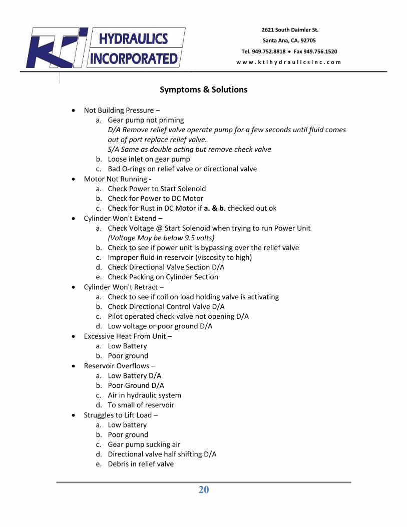
Symptoms & Solutions
x Not Building Pressure –
a. Gear pump not priming D/A Remove relief valve operate pump for a few seconds until fluid comes out of port replace relief valve. S/A Same as double acting but remove check valve
b. Loose inlet on gear pump c. Bad O-rings on relief valve or directional valve
x Motor Not Running - a. Check Power to Start Solenoid b. Check for Power to DC Motor c. Check for Rust in DC Motor if a. & b. checked out ok
x Cylinder Won't Extend – a. Check Voltage @ Start Solenoid when trying to run Power Unit
(Voltage May be below 9.5 volts) b. Check to see if power unit is bypassing over the relief valve c. Improper fluid in reservoir (viscosity to high) d. Check Directional Valve Section D/A e. Check Packing on Cylinder Section
x Cylinder Won't Retract – a. Check to see if coil on load holding valve is activating b. Check Directional Control Valve D/A c. Pilot operated check valve not opening D/A d. Low voltage or poor ground D/A
x Excessive Heat From Unit – a. Low Battery b. Poor ground
x Reservoir Overflows – a. Low Battery D/A b. Poor Ground D/A c. Air in hydraulic system d. To small of reservoir
x Struggles to Lift Load – a. Low battery b. Poor ground c. Gear pump sucking air d. Directional valve half shifting D/A e. Debris in relief valve
21
2621 South Daimler St.
Santa Ana, CA. 92705
Tel. 949.752.8818 x Fax 949.756.1520
w w w . k t i h y d r a u l i c s i n c . c o m
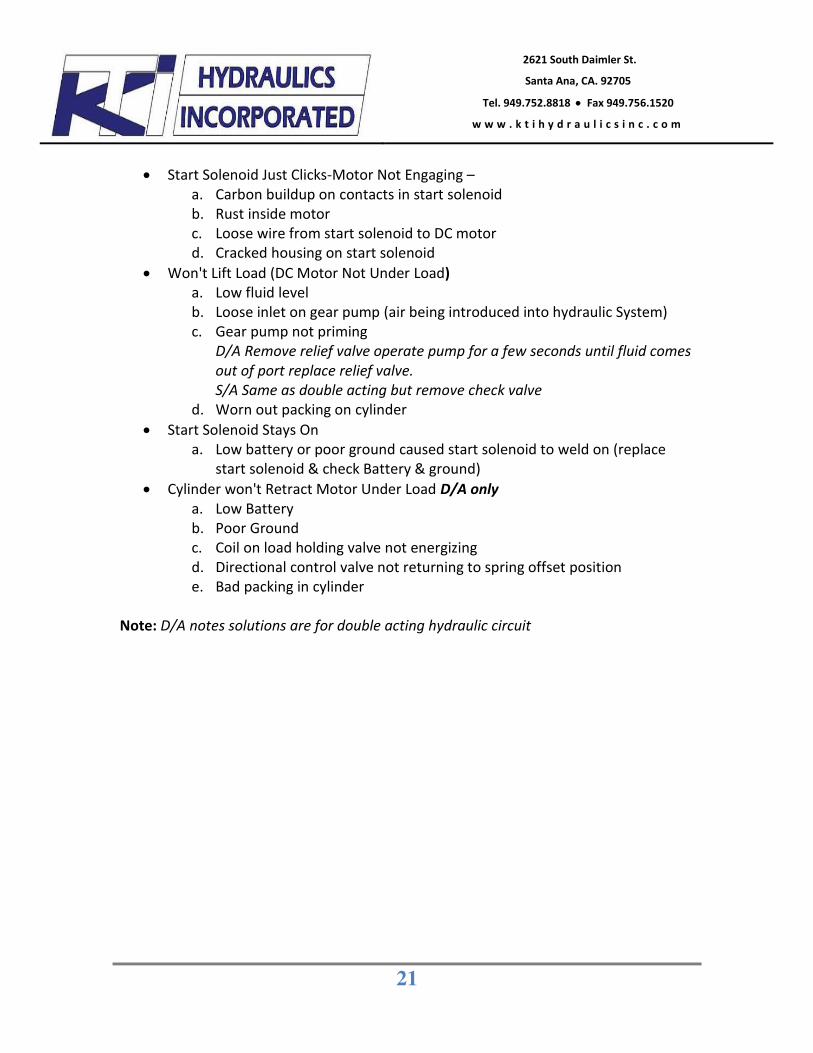
x Start Solenoid Just Clicks-Motor Not Engaging –
a. Carbon buildup on contacts in start solenoid b. Rust inside motor c. Loose wire from start solenoid to DC motor d. Cracked housing on start solenoid
x Won't Lift Load (DC Motor Not Under Load) a. Low fluid level b. Loose inlet on gear pump (air being introduced into hydraulic System) c. Gear pump not priming
D/A Remove relief valve operate pump for a few seconds until fluid comes out of port replace relief valve. S/A Same as double acting but remove check valve
d. Worn out packing on cylinder x Start Solenoid Stays On
a. Low battery or poor ground caused start solenoid to weld on (replace start solenoid & check Battery & ground)
x Cylinder won't Retract Motor Under Load D/A only a. Low Battery b. Poor Ground c. Coil on load holding valve not energizing d. Directional control valve not returning to spring offset position e. Bad packing in cylinder
Note: D/A notes solutions are for double acting hydraulic circuit
22
2621 South Daimler St.
Santa Ana, CA. 92705
Tel. 949.752.8818 x Fax 949.756.1520
w w w . k t i h y d r a u l i c s i n c . c o m
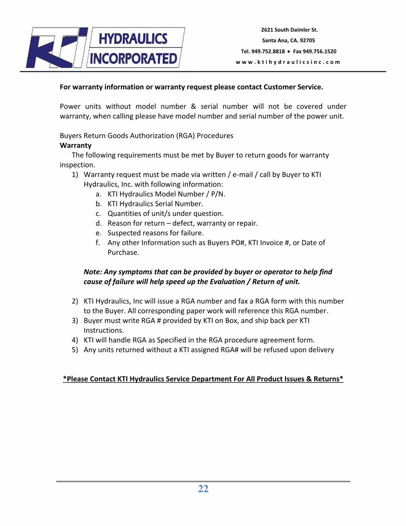
For warranty information or warranty request please contact Customer Service. Power units without model number & serial number will not be covered under warranty, when calling please have model number and serial number of the power unit. Buyers Return Goods Authorization (RGA) Procedures Warranty
The following requirements must be met by Buyer to return goods for warranty inspection.
1) Warranty request must be made via written / e-mail / call by Buyer to KTI Hydraulics, Inc. with following information:
a. KTI Hydraulics Model Number / P/N. b. KTI Hydraulics Serial Number. c. Quantities of unit/s under question. d. Reason for return – defect, warranty or repair. e. Suspected reasons for failure. f. Any other Information such as Buyers PO#, KTI Invoice #, or Date of
Purchase.
Note: Any symptoms that can be provided by buyer or operator to help find cause of failure will help speed up the Evaluation / Return of unit.
2) KTI Hydraulics, Inc will issue a RGA number and fax a RGA form with this number
to the Buyer. All corresponding paper work will reference this RGA number. 3) Buyer must write RGA # provided by KTI on Box, and ship back per KTI
Instructions. 4) KTI will handle RGA as Specified in the RGA procedure agreement form. 5) Any units returned without a KTI assigned RGA# will be refused upon delivery
*Please Contact KTI Hydraulics Service Department For All Product Issues & Returns*
23
2621 South Daimler St.
Santa Ana, CA. 92705
Tel. 949.752.8818 x Fax 949.756.1520
w w w . k t i h y d r a u l i c s i n c . c o m
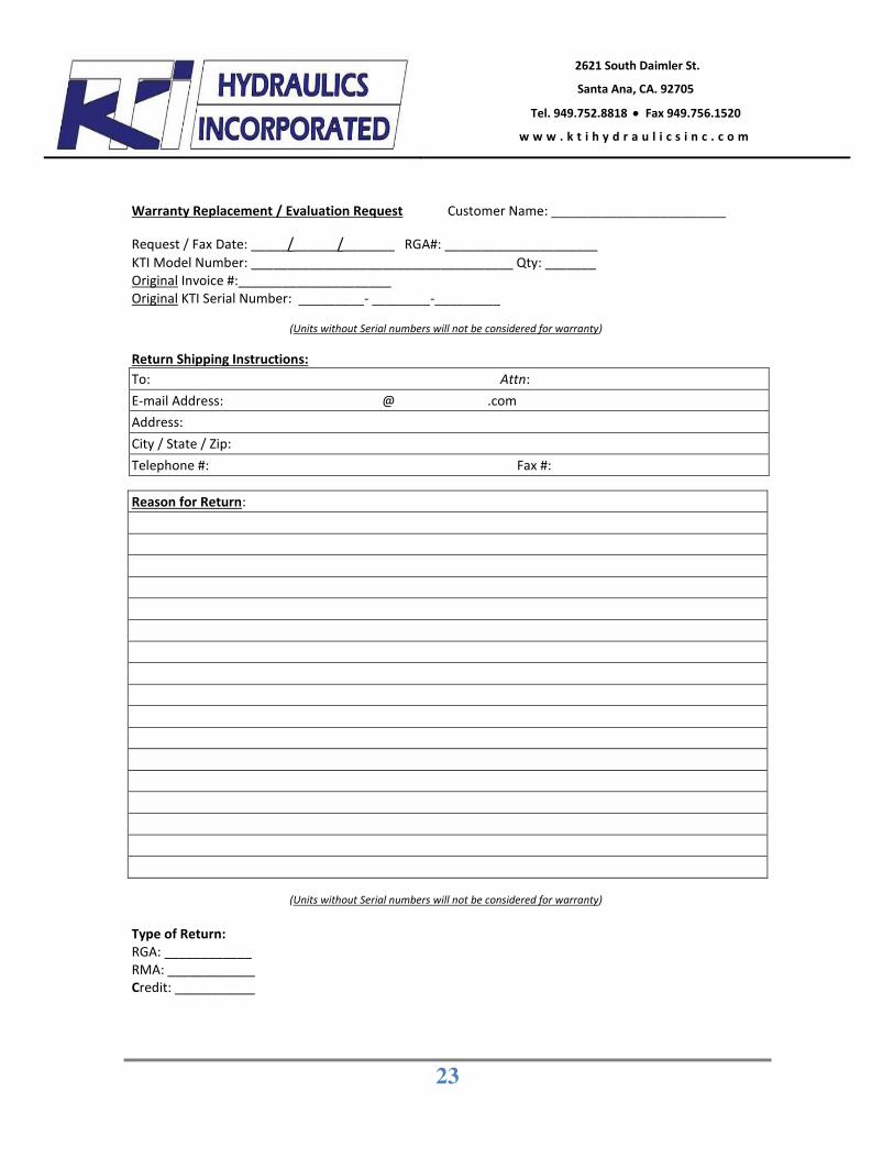
Warranty Replacement / Evaluation Request Customer Name: ________________________ Request / Fax Date: _____/______/_______ RGA#: _____________________ KTI Model Number: ____________________________________ Qty: _______ Original Invoice #:_____________________ Original KTI Serial Number: _________- ________-_________ (Units without Serial numbers will not be considered for warranty)
Return Shipping Instructions: To: Attn: E-mail Address: @ .com Address: City / State / Zip: Telephone #: Fax #:
Reason for Return:
(Units without Serial numbers will not be considered for warranty) Type of Return: RGA: ____________ RMA: ____________ Credit: ___________