66
Manual 6609E GK ® 11"-5000 PSI Annular Blowout Preventer OPERATOR'S MANUAL R Pressure Control Equipment
| Date post: | 19-Jan-2016 |
| Category: |
Documents |
| Upload: | boris-zaslichko |
| View: | 1,918 times |
| Download: | 176 times |
Manual 6609E
GK® 11"-5000 PSIAnnular Blowout Preventer
OP
ER
ATO
R'S
MA
NU
AL
R
Pressure Control Equipment
R
PAGEiii
Operator's ManualGK® 11"-5000 PSI Annular Blowout Preventer
GK® 11"-5000 PSI Annular Blowout Preventer
OPERATOR'S MANUAL6609E
R
© 2007 Hydril Company LP Printed in U.S.A., Rev E, October 2007 All Rights Reserved
Hydril Company LP/ P.O. Box 60458 / Houston, Texas 77205Phone: (281) 449-2000 / FAX: (281) 985-2828 / WEB: www.hydril.com
R
PAGEiv
Operator's ManualGK® 11"-5000 PSI Annular Blowout Preventer
Preface
This manual contains the information necessary to operate and maintain the Hydril® GK® 11"-5000 PSI Annular BlowoutPreventer (ABOP). Hydril recommends that the information in this manual be studied thoroughly before any attemptis made to operate or perform maintenance or repair operations on this equipment and that all safety precautions befollowed.
Generic in construction, this manual is applicable for the operation and maintenance of all GK 11"-5000 ABOPsmanufactured by Hydril. The illustrations of assemblies and operation and maintenance procedures in this manualare typical and represent most configurations. Variations in configuration are noted in the procedures whereapplicable. In addition, illustrated parts lists are provided for component replacement.
R
PAGEv
Operator's ManualGK® 11"-5000 PSI Annular Blowout Preventer
PAGE
Preface . . . . . . . . . . . . . . . . . . . . . . . . . . . . . . . . . . . . . . . . . . . . . . . . . . . . . . . . . . . . . . . . . . . . . . . . . . . . . . . . . . . . iv
OPERATOR QUICK REFERENCE . . . . . . . . . . . . . . . . . . . . . . . . . . . . . . . . . . . . . . . . . . . . . . . . . . . . . vii
SECTION 1.0 – INSTALLATION AND OPERATION
1.1 Installation . . . . . . . . . . . . . . . . . . . . . . . . . . . . . . . . . . . . . . . . . . . . . . . . . . . . . . . . . . . . . . . . . . . . . . . . . . . . . . . . . 1-11.1.1 Safety Precautions . . . . . . . . . . . . . . . . . . . . . . . . . . . . . . . . . . . . . . . . . . . . . . . . . . . . . . . . . . . . . . . . . . . . 1-11.1.2 Weights and Dimensions . . . . . . . . . . . . . . . . . . . . . . . . . . . . . . . . . . . . . . . . . . . . . . . . . . . . . . . . . . . . . . 1-11.1.3 Annular BOP Removal and Installation Procedures . . . . . . . . . . . . . . . . . . . . . . . . . . . . . . . . . . . . . . . 1-1
A. Annular BOP Removal Procedure . . . . . . . . . . . . . . . . . . . . . . . . . . . . . . . . . . . . . . . . . . . . . . . . . . . . 1-1B. Annular BOP Installation Procedure . . . . . . . . . . . . . . . . . . . . . . . . . . . . . . . . . . . . . . . . . . . . . . . . . . 1-1
1.2 Operation . . . . . . . . . . . . . . . . . . . . . . . . . . . . . . . . . . . . . . . . . . . . . . . . . . . . . . . . . . . . . . . . . . . . . . . . . . . . . . . . . 1-31.2.1 Operating Procedures . . . . . . . . . . . . . . . . . . . . . . . . . . . . . . . . . . . . . . . . . . . . . . . . . . . . . . . . . . . . . . . . . 1-3
A. Opening the Annular BOP . . . . . . . . . . . . . . . . . . . . . . . . . . . . . . . . . . . . . . . . . . . . . . . . . . . . . . . . . . . 1-3B. Closing the Annular BOP . . . . . . . . . . . . . . . . . . . . . . . . . . . . . . . . . . . . . . . . . . . . . . . . . . . . . . . . . . . . 1-3
1.2.2 Operating Data . . . . . . . . . . . . . . . . . . . . . . . . . . . . . . . . . . . . . . . . . . . . . . . . . . . . . . . . . . . . . . . . . . . . . . . 1-31.2.3 Operational Characteristics Summary . . . . . . . . . . . . . . . . . . . . . . . . . . . . . . . . . . . . . . . . . . . . . . . . . . . 1-31.2.4 Principle of Operation . . . . . . . . . . . . . . . . . . . . . . . . . . . . . . . . . . . . . . . . . . . . . . . . . . . . . . . . . . . . . . . . . . 1-41.2.5 Surface Operation and Hookup . . . . . . . . . . . . . . . . . . . . . . . . . . . . . . . . . . . . . . . . . . . . . . . . . . . . . . . . . 1-61.2.6 Surface Stripping Operations . . . . . . . . . . . . . . . . . . . . . . . . . . . . . . . . . . . . . . . . . . . . . . . . . . . . . . . . . . . 1-7
SECTION 2.0 – PHYSICAL DATA
2.1 Engineering Data . . . . . . . . . . . . . . . . . . . . . . . . . . . . . . . . . . . . . . . . . . . . . . . . . . . . . . . . . . . . . . . . . . . . . . . . . . . . 2-12.2 Bolt and Wrench Data . . . . . . . . . . . . . . . . . . . . . . . . . . . . . . . . . . . . . . . . . . . . . . . . . . . . . . . . . . . . . . . . . . . . . . . . 2-12.3 Lubricant List . . . . . . . . . . . . . . . . . . . . . . . . . . . . . . . . . . . . . . . . . . . . . . . . . . . . . . . . . . . . . . . . . . . . . . . . . . . . . . . 2-12.4 Dimensions - Screwed Head . . . . . . . . . . . . . . . . . . . . . . . . . . . . . . . . . . . . . . . . . . . . . . . . . . . . . . . . . . . . . . . . . 2-22.5 Dimensions - Latch Head . . . . . . . . . . . . . . . . . . . . . . . . . . . . . . . . . . . . . . . . . . . . . . . . . . . . . . . . . . . . . . . . . . . 2-32.6 API Ring Joint Flange Connections . . . . . . . . . . . . . . . . . . . . . . . . . . . . . . . . . . . . . . . . . . . . . . . . . . . . . . . . . . . 2-42.7 Clamp Hub Connections . . . . . . . . . . . . . . . . . . . . . . . . . . . . . . . . . . . . . . . . . . . . . . . . . . . . . . . . . . . . . . . . . . . . . 2-5
SECTION 3.0 – PACKING UNITS AND SEALS
3.1 Packing Units . . . . . . . . . . . . . . . . . . . . . . . . . . . . . . . . . . . . . . . . . . . . . . . . . . . . . . . . . . . . . . . . . . . . . . . . . . . . . . 3-13.1.1 Packing Unit Selection . . . . . . . . . . . . . . . . . . . . . . . . . . . . . . . . . . . . . . . . . . . . . . . . . . . . . . . . . . . . . . . . . 3-23.1.2 Packing Unit Replacement-Screwed Head . . . . . . . . . . . . . . . . . . . . . . . . . . . . . . . . . . . . . . . . . . . . . . . 3-33.1.3 Packing Unit Replacement-Latch Head . . . . . . . . . . . . . . . . . . . . . . . . . . . . . . . . . . . . . . . . . . . . . . . . . . 3-4
3.2 Seals . . . . . . . . . . . . . . . . . . . . . . . . . . . . . . . . . . . . . . . . . . . . . . . . . . . . . . . . . . . . . . . . . . . . . . . . . . . . . . . . . . . . . . 3-53.3 Wear Bands . . . . . . . . . . . . . . . . . . . . . . . . . . . . . . . . . . . . . . . . . . . . . . . . . . . . . . . . . . . . . . . . . . . . . . . . . . . . . . . . 3-6
SECTION 4.0 – MAINTENANCE AND TESTING
4.1 Troubleshooting . . . . . . . . . . . . . . . . . . . . . . . . . . . . . . . . . . . . . . . . . . . . . . . . . . . . . . . . . . . . . . . . . . . . . . . . . . . . 4-14.2 Maintenance Schedule . . . . . . . . . . . . . . . . . . . . . . . . . . . . . . . . . . . . . . . . . . . . . . . . . . . . . . . . . . . . . . . . . . . . . . 4-14.3 Inspection . . . . . . . . . . . . . . . . . . . . . . . . . . . . . . . . . . . . . . . . . . . . . . . . . . . . . . . . . . . . . . . . . . . . . . . . . . . . . . . . . . 4-34.4 Seal Testing - GK® Without Wear Bands . . . . . . . . . . . . . . . . . . . . . . . . . . . . . . . . . . . . . . . . . . . . . . . . . . . . . . . 4-44.5 Seal Testing - GK® With Wear Bands . . . . . . . . . . . . . . . . . . . . . . . . . . . . . . . . . . . . . . . . . . . . . . . . . . . . . . . . . . 4-54.6 Packing Unit Testing . . . . . . . . . . . . . . . . . . . . . . . . . . . . . . . . . . . . . . . . . . . . . . . . . . . . . . . . . . . . . . . . . . . . . . . . 4-64.7 BOP Modifications . . . . . . . . . . . . . . . . . . . . . . . . . . . . . . . . . . . . . . . . . . . . . . . . . . . . . . . . . . . . . . . . . . . . . . . . . . 4-7
SECTION 5.0 – DISASSEMBLY AND ASSEMBLY
5.1 Disassembly - Screwed Head Without Wear Bands . . . . . . . . . . . . . . . . . . . . . . . . . . . . . . . . . . . . . . . . . . . . . 5-15.2 Assembly - Screwed Head Without Wear Bands . . . . . . . . . . . . . . . . . . . . . . . . . . . . . . . . . . . . . . . . . . . . . . . . 5-35.3 Disassembly - Screwed Head With Wear Bands . . . . . . . . . . . . . . . . . . . . . . . . . . . . . . . . . . . . . . . . . . . . . . . . 5-65.4 Assembly - Screwed Head With Wear Bands . . . . . . . . . . . . . . . . . . . . . . . . . . . . . . . . . . . . . . . . . . . . . . . . . . . 5-8
CONTENTS
R
PAGEvi
Operator's ManualGK® 11"-5000 PSI Annular Blowout Preventer
SECTION 5.0 – DISSASSEMBLY AND ASSEMBLY (CONTINUED)
5.5 Disassembly - Latched Head Without Wear Bands . . . . . . . . . . . . . . . . . . . . . . . . . . . . . . . . . . . . . . . . . . . . . 5-115.6 Assembly - Latched Head Without Wear Bands . . . . . . . . . . . . . . . . . . . . . . . . . . . . . . . . . . . . . . . . . . . . . . . . 5-135.7 Disassembly - Latched Head With Wear Bands . . . . . . . . . . . . . . . . . . . . . . . . . . . . . . . . . . . . . . . . . . . . . . . . 5-165.8 Assembly - Latched Head With Wear Bands . . . . . . . . . . . . . . . . . . . . . . . . . . . . . . . . . . . . . . . . . . . . . . . . . . . 5-18
SECTION 6.0 – PARTS AND STORAGE
6.1 Parts List - Screwed Head Without Wear Bands . . . . . . . . . . . . . . . . . . . . . . . . . . . . . . . . . . . . . . . . . . . . . . . 6-16.2A Parts List - Screwed Head With Wear Band Modification . . . . . . . . . . . . . . . . . . . . . . . . . . . . . . . . . . . . . . . . 6-26.2B Parts List - Screwed Head Wear Band Modification Kit . . . . . . . . . . . . . . . . . . . . . . . . . . . . . . . . . . . . . . . . . . 6-36.3 Parts List - Screwed Head With Wear Bands At Manufacture . . . . . . . . . . . . . . . . . . . . . . . . . . . . . . . . . . . . . 6-46.4 Parts List - Latched Head Without Wear Bands . . . . . . . . . . . . . . . . . . . . . . . . . . . . . . . . . . . . . . . . . . . . . . . . 6-56.5A Parts List - Latched Head With Wear Band Modification . . . . . . . . . . . . . . . . . . . . . . . . . . . . . . . . . . . . . . . . 6-66.5B Parts List - Latched Head Wear Band Modification Kit . . . . . . . . . . . . . . . . . . . . . . . . . . . . . . . . . . . . . . . . . . 6-76.6 Parts List - Latched Head With Wear Bands At Manufacture . . . . . . . . . . . . . . . . . . . . . . . . . . . . . . . . . . . . . 6-86.7 Preventor Storage . . . . . . . . . . . . . . . . . . . . . . . . . . . . . . . . . . . . . . . . . . . . . . . . . . . . . . . . . . . . . . . . . . . . . . . . . 6-96.8 Rubber Goods Storage . . . . . . . . . . . . . . . . . . . . . . . . . . . . . . . . . . . . . . . . . . . . . . . . . . . . . . . . . . . . . . . . . . . . . 6-10
CONTENTS (CONTINUED)
1-viiR
PAGEvii
Operator's ManualGK® 11"-5000 PSI Annular Blowout Preventer
OpeningPressure
ClosingPressure
OPERATOR QUICK REFERENCE
▲▲▲▲▲Surface Control Pressure —psi
WELL PRESSURE—psiInitial*
Pipe Size Closure 500 1500 2500 3500 5000
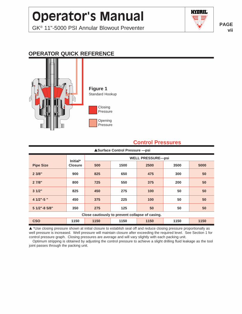
2 3/8” 900 825 650 475 300 50
2 7/8" 800 725 550 375 200 50
3 1/2" 825 450 275 100 50 50
4 1/2"-5 " 450 375 225 100 50 50
5 1/2"-8 5/8" 350 275 125 50 50 50
CSO 1150 1150 1150 1150 1150 1150
Close cautiously to prevent collapse of casing.
▲ *Use closing pressure shown at initial closure to establish seal off and reduce closing pressure proportionally aswell pressure is increased. Well pressure will maintain closure after exceeding the required level. See Section 1 forcontrol pressure graph. Closing pressures are average and will vary slightly with each packing unit.
Optimum stripping is obtained by adjusting the control pressure to achieve a slight drilling fluid leakage as the tooljoint passes through the packing unit.
Control Pressures
Figure 1Standard Hookup
1-viiiR
PAGEviii
Operator's ManualGK® 11"-5000 PSI Annular Blowout Preventer
Proper Procedure for pressure testing any annular blow-out preventer (BOP) ensures subsequent seal off andmaximum packing unit life. Reliable seal off tests are madeby initially closing the packing unit with prescribed closingchamber pressure on the recommended size test pipe,proportionally reducing closing pressure as well pressureis increased, and by determining the remaining pistontravel after seal off is achieved. Optimum packing unit lifeis obtained by testing at low rubber stress levels. Minimumpacking unit stress is achieved by use of the minimumclosing chamber pressure that will initiate and maintainseal off on the recommended size test pipe.
The GK® blowout preventer is designed to be wellpressure assisted in maintaining packing unit seal off onceinitial seal off has been effected. Initial seal off is effectedby applying pressure to the closing chamber. As wellpressure or test pressure is increased, the closing force onthe packing unit also increases. As well pressure exceedsthe required level the packing unit is maintained closed onthe recommended size test pipe by well pressure alone.Once initial seal off is achieved, it is recommended thatclosing pressure be proportionally reduced as well pres-sure is increased in order to maintain the optimum closing
force on the packing unit. Optimum closing forces for highwell pressures may require careful application of pressureto the opening chamber. Closing pressure required toeffect initial seal off may vary slightly between individualpacking units. Begin the test with the recommended initialclosing pressure.
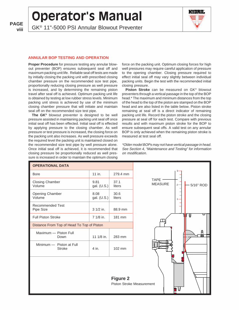
Piston Stroke can be measured on GK® blowoutpreventers through a vertical passage in the top of the BOPhead.* The maximum and minimum distances from the topof the head to the top of the piston are stamped on the BOPhead and are also listed in the table below. Piston strokeremaining at seal off is a direct indicator of remainingpacking unit life. Record the piston stroke and the closingpressure at seal off for each test. Compare with previousresults and with maximum piston stroke for the BOP toensure subsequent seal offs. A valid test on any annularBOP is only achieved when the remaining piston stroke ismeasured at test seal off.
*Older model BOPs may not have vertical passage in head.See Section 4, “Maintenance and Testing” for informationon modification.
ANNULAR BOP TESTING AND OPERATION
OPERATIONAL DATA
Bore 11 in. 279.4 mm
Closing Chamber 9.81 37.1Volume gal. (U.S.) liters
Opening Chamber 8.08 30.6Volume gal. (U.S.) liters
Recommended TestPipe Size 3 1/2 in. 88.9 mm
Full Piston Stroke 7 1/8 in. 181 mm
Distance From Top of Head To Top of Piston
Maximum — Piston FullDown 11 1/8 in. 283 mm
Minimum — Piston at FullStroke 4 in. 102 mm
TAPEMEASURE
3
2
1
5/16" ROD
Figure 2Piston Stroke Measurement
R
PAGE1-1
Operator's ManualGK® 11"-5000 PSI Annular Blowout Preventer
1.0 INSTALLATION AND OPERATION
1.1 Installation
1.1.1 Safety Precautions
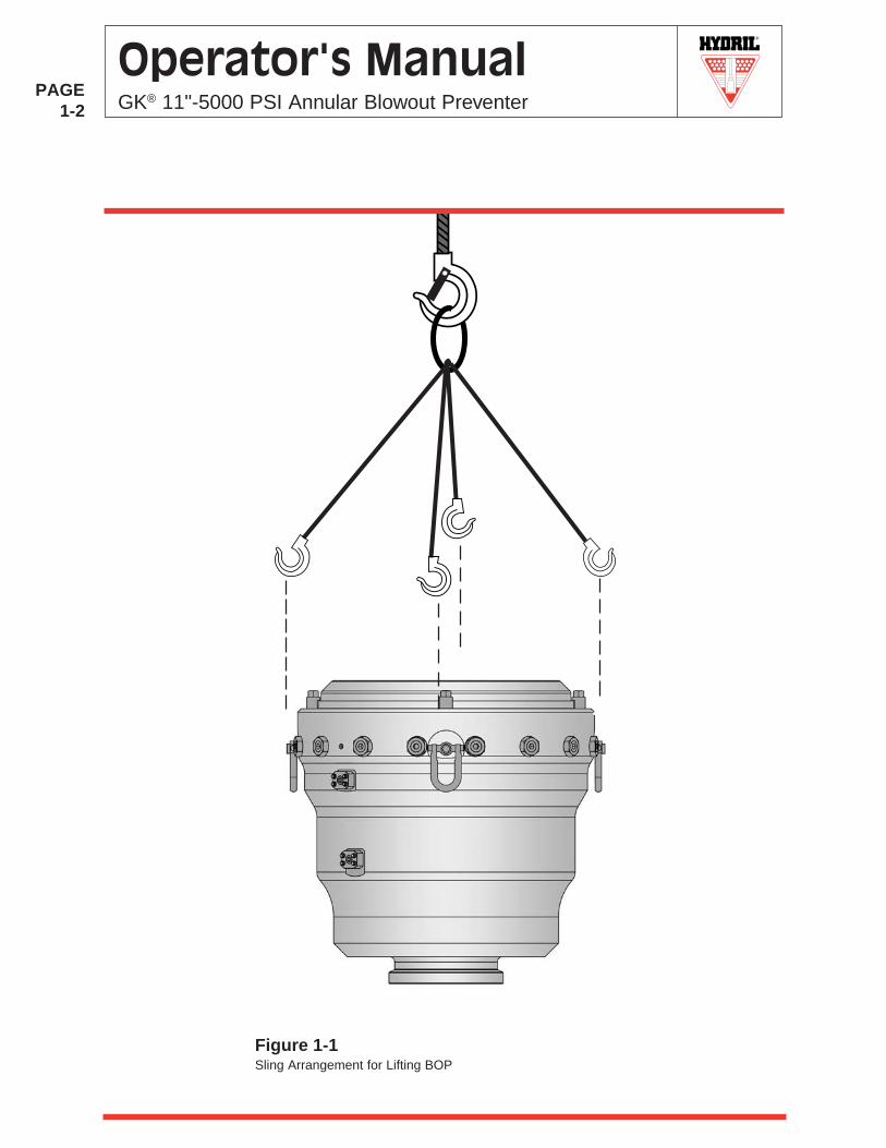
WARNING: THIS IS VERY HEAVY EQUIPMENT, ANDEXTREME SAFETY PROCEDURES MUST BE FOL-LOWED DURING LIFTING OPERATIONS. BE SURETHAT LIFTING EQUIPMENT IS IN GOOD CONDITIONAND CAPABLE OF HANDLING THE LOAD.
WARNING: DO NOT USE THE FOUR LIFT EYESMOUNTED ON THE ANNULAR BOP BODY TO LIFT THEBOP STACK ASSEMBLY. THESE LIFT EYES ARE FORLIFTING THE GK 11"-5000 PSI ANNULAR BOP ASSEM-BLY ONLY.
1.1.2 Weight and DimensionsFor dimensions and weight, refer to Section 2,"PhysicalData."
1.1.3 Annular BOP Removal and InstallationProceduresNOTE: For initial installation, refer to “Surface Operationand Hookup” and “Surface Stripping Operations” in thissection for information on connection of hydraulic operat-ing lines to the blowout preventer.
The GK 11"-5000 PSI Annular BOP is usually installedat the top of a BOP stack. Normally, the annular BOP doesnot require removal from the BOP stack and subsequentinstallation for field repair. The procedures below areintended for those circumstances where the annular BOPwould require removal from the BOP stack for inspection ofthe bottom connection or for other reasons and subse-quently would require installation again.
A. Annular BOP Removal Procedure1. Gather a lifting apparatus for lifting the annular BOP
assembly. CAUTION: Ensure that the lifting appara-tus is adequate to safely support the weight of theannular BOP assembly. NOTE: Refer to Section 2,"Physical Data" for estimated weight.
2. Disassemble the BOP stack to the point where theannular BOP can be removed.
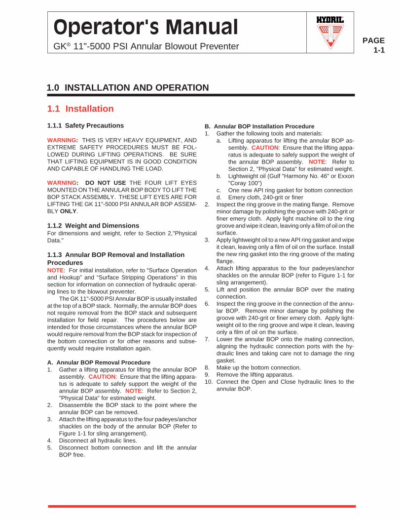
3. Attach the lifting apparatus to the four padeyes/anchorshackles on the body of the annular BOP (Refer toFigure 1-1 for sling arrangement).
4. Disconnect all hydraulic lines.5. Disconnect bottom connection and lift the annular
BOP free.
B. Annular BOP Installation Procedure1. Gather the following tools and materials:
a. Lifting apparatus for lifting the annular BOP as-sembly. CAUTION: Ensure that the lifting appa-ratus is adequate to safely support the weight ofthe annular BOP assembly. NOTE: Refer toSection 2, "Physical Data" for estimated weight.
b. Lightweight oil (Gulf "Harmony No. 46" or Exxon"Coray 100")
c. One new API ring gasket for bottom connectiond. Emery cloth, 240-grit or finer
2. Inspect the ring groove in the mating flange. Removeminor damage by polishing the groove with 240-grit orfiner emery cloth. Apply light machine oil to the ringgroove and wipe it clean, leaving only a film of oil on thesurface.
3. Apply lightweight oil to a new API ring gasket and wipeit clean, leaving only a film of oil on the surface. Installthe new ring gasket into the ring groove of the matingflange.
4. Attach lifting apparatus to the four padeyes/anchorshackles on the annular BOP (refer to Figure 1-1 forsling arrangement).
5. Lift and position the annular BOP over the matingconnection.
6. Inspect the ring groove in the connection of the annu-lar BOP. Remove minor damage by polishing thegroove with 240-grit or finer emery cloth. Apply light-weight oil to the ring groove and wipe it clean, leavingonly a film of oil on the surface.
7. Lower the annular BOP onto the mating connection,aligning the hydraulic connection ports with the hy-draulic lines and taking care not to damage the ringgasket.
8. Make up the bottom connection.9. Remove the lifting apparatus.10. Connect the Open and Close hydraulic lines to the
annular BOP.
R
PAGE1-2
Operator's ManualGK® 11"-5000 PSI Annular Blowout Preventer
Figure 1-1Sling Arrangement for Lifting BOP
R
PAGE1-3
Operator's ManualGK® 11"-5000 PSI Annular Blowout Preventer
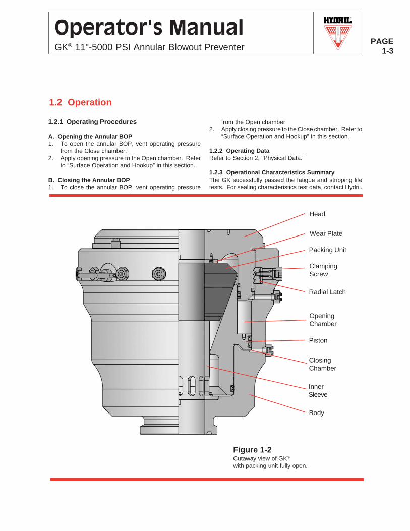
Head
Packing Unit
OpeningChamber
Piston
ClosingChamber
InnerSleeve
Body
Radial Latch
ClampingScrew
Figure 1-2Cutaway view of GK®
with packing unit fully open.
Wear Plate
1.2 Operation
1.2.1 Operating Procedures
A. Opening the Annular BOP1. To open the annular BOP, vent operating pressure
from the Close chamber.2. Apply opening pressure to the Open chamber. Refer
to “Surface Operation and Hookup” in this section.
B. Closing the Annular BOP1. To close the annular BOP, vent operating pressure
from the Open chamber.2. Apply closing pressure to the Close chamber. Refer to
“Surface Operation and Hookup” in this section.
1.2.2 Operating DataRefer to Section 2, "Physical Data."
1.2.3 Operational Characteristics SummaryThe GK sucessfully passed the fatigue and stripping lifetests. For sealing characteristics test data, contact Hydril.
R
PAGE1-4
Operator's ManualGK® 11"-5000 PSI Annular Blowout Preventer
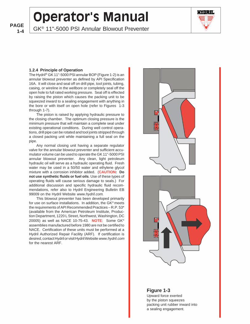
Figure 1-3Upward force exertedby the piston squeezespacking unit rubber inward intoa sealing engagement.
1.2.4 Principle of OperationThe Hydril® GK 11"-5000 PSI annular BOP (Figure 1-2) is anannular blowout preventer as defined by API Specification16A. It will close and seal off on drill pipe, tool joints, tubing,casing, or wireline in the wellbore or completely seal off theopen hole to full rated working pressure. Seal off is effectedby raising the piston which causes the packing unit to besqueezed inward to a sealing engagement with anything inthe bore or with itself on open hole (refer to Figures 1-3through 1-7).
The piston is raised by applying hydraulic pressure tothe closing chamber. The optimum closing pressure is theminimum pressure that will maintain a complete seal underexisting operational conditions. During well control opera-tions, drill pipe can be rotated and tool joints stripped througha closed packing unit while maintaining a full seal on thepipe.
Any normal closing unit having a separate regulatorvalve for the annular blowout preventer and sufficient accu-mulator volume can be used to operate the GK 11"-5000 PSIannular blowout preventer. Any clean, light petroleumhydraulic oil will serve as a hydraulic operating fluid. Freshwater may be used in a 50/50 water and ethylene glycolmixture with a corrosion inhibitor added. (CAUTION: Donot use synthetic fluids or fuel oils. Use of these types ofoperating fluids will cause serious damage to seals.) Foradditional discussion and specific hydraulic fluid recom-mendations, refer also to Hydril Engineering Bulletin EB99009 on the Hydril Website www.hydril.com.
This blowout preventer has been developed primarilyfor use on surface installations. In addition, the GK® meetsthe requirements of API Recommended Practices – R.P. 53*(available from the American Petroleum Institute, Produc-tion Department, 1220 L Street, Northwest, Washington, DC20005) as well as NACE 10-75-43. NOTE: Some GK®
assemblies manufactured before 1980 are not be certified toNACE. Certification of these units must be performed at aHydril Authorized Repair Facility (ARF). If certification isdesired, contact Hydril or visit Hydril Website www.hydril.comfor the nearest ARF.
R
PAGE1-5
Operator's ManualGK® 11"-5000 PSI Annular Blowout Preventer
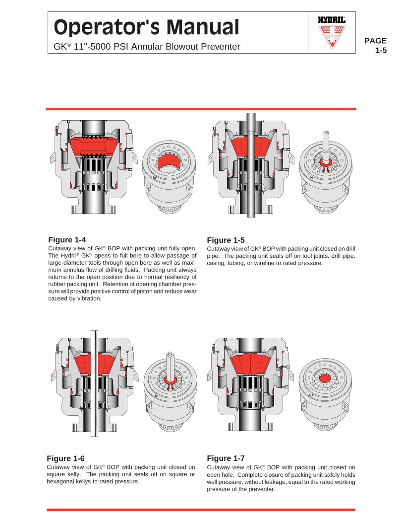
Figure 1-7Cutaway view of GK® BOP with packing unit closed onopen hole. Complete closure of packing unit safely holdswell pressure, without leakage, equal to the rated workingpressure of the preventer.
Figure 1-6Cutaway view of GK® BOP with packing unit closed onsquare kelly. The packing unit seals off on square orhexagonal kellys to rated pressure.
Figure 1-4Cutaway view of GK® BOP with packing unit fully open.The Hydril® GK® opens to full bore to allow passage oflarge-diameter tools through open bore as well as maxi-mum annulus flow of drilling fluids. Packing unit alwaysreturns to the open position due to normal resiliency ofrubber packing unit. Retention of opening chamber pres-sure will provide positive control of piston and reduce wearcaused by vibration.
Figure 1-5Cutaway view of GK® BOP with packing unit closed on drillpipe. The packing unit seals off on tool joints, drill pipe,casing, tubing, or wireline to rated pressure.
R
PAGE1-6
Operator's ManualGK® 11"-5000 PSI Annular Blowout Preventer
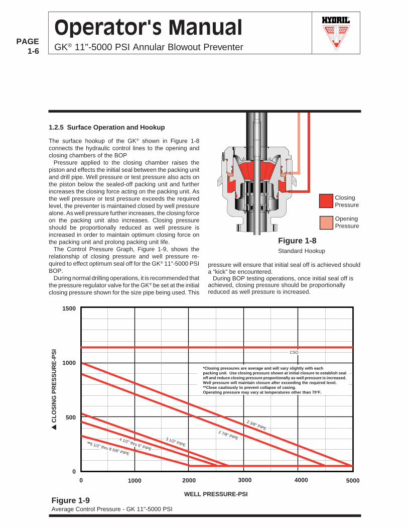
1.2.5 Surface Operation and Hookup
Figure 1-8Standard Hookup
OpeningPressure
The surface hookup of the GK® shown in Figure 1-8connects the hydraulic control lines to the opening andclosing chambers of the BOP
Pressure applied to the closing chamber raises thepiston and effects the initial seal between the packing unitand drill pipe. Well pressure or test pressure also acts onthe piston below the sealed-off packing unit and furtherincreases the closing force acting on the packing unit. Asthe well pressure or test pressure exceeds the requiredlevel, the preventer is maintained closed by well pressurealone. As well pressure further increases, the closing forceon the packing unit also increases. Closing pressureshould be proportionally reduced as well pressure isincreased in order to maintain optimum closing force onthe packing unit and prolong packing unit life.
The Control Pressure Graph, Figure 1-9, shows therelationship of closing pressure and well pressure re-quired to effect optimum seal off for the GK® 11”-5000 PSIBOP.
During normal drilling operations, it is recommended thatthe pressure regulator valve for the GK® be set at the initialclosing pressure shown for the size pipe being used. This
pressure will ensure that initial seal off is achieved shoulda “kick” be encountered.
During BOP testing operations, once initial seal off isachieved, closing pressure should be proportionallyreduced as well pressure is increased.
WELL PRESSURE-PSI
1000
0 1000 2000 3000
500
1500
0
Figure 1-9Average Control Pressure - GK 11"-5000 PSI
▲
▲
▲
▲
▲ C
LO
SIN
G P
RE
SS
UR
E-P
SI
4000 5000
**5 1/2" thru 8 5/8" PIPE
4 1/2" thru 5" PIPE
3 1/2" PIPE
2 7/8" PIPE
2 3/8" PIPE
CSO
*Closing pressures are average and will vary slightly with eachpacking unit. Use closing pressure shown at initial closure to establish sealoff and reduce closing pressure proportionally as well pressure is increased.Well pressure will maintain closure after exceeding the required level.**Close cautiously to prevent collapse of casing.Operating pressure may vary at temperatures other than 70oF.
ClosingPressure
R
PAGE1-7
Operator's ManualGK® 11"-5000 PSI Annular Blowout Preventer
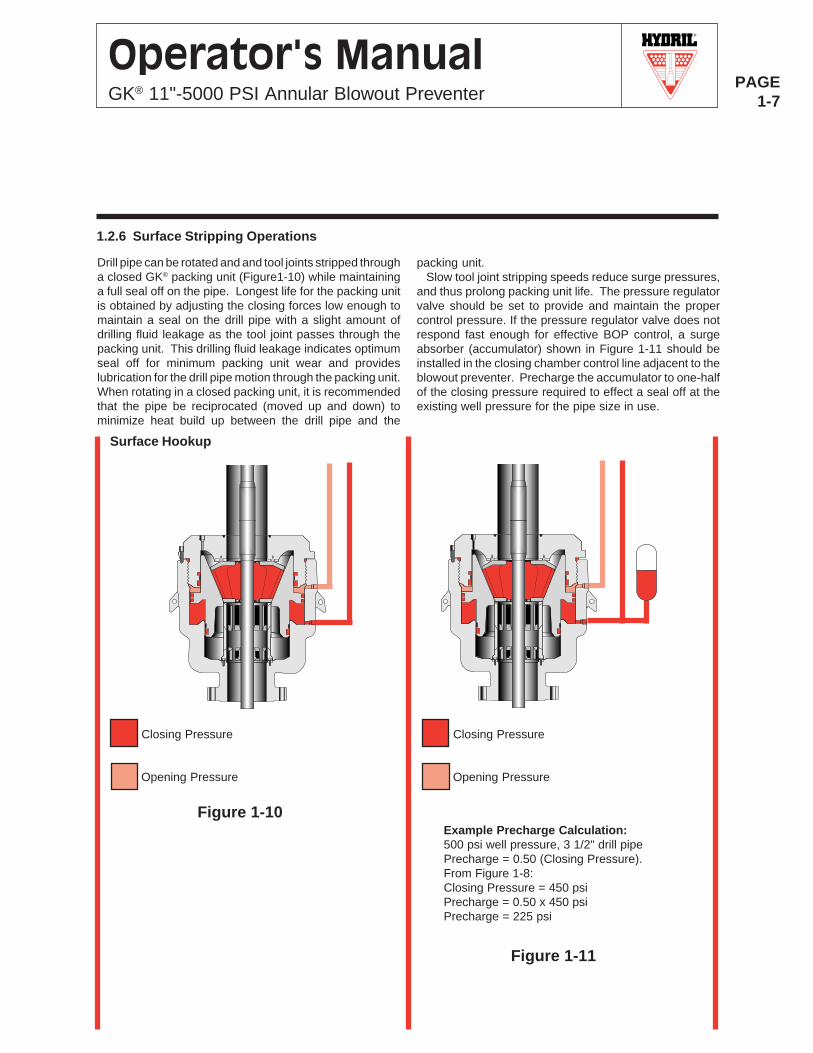
1.2.6 Surface Stripping Operations
Drill pipe can be rotated and and tool joints stripped througha closed GK® packing unit (Figure1-10) while maintaininga full seal off on the pipe. Longest life for the packing unitis obtained by adjusting the closing forces low enough tomaintain a seal on the drill pipe with a slight amount ofdrilling fluid leakage as the tool joint passes through thepacking unit. This drilling fluid leakage indicates optimumseal off for minimum packing unit wear and provideslubrication for the drill pipe motion through the packing unit.When rotating in a closed packing unit, it is recommendedthat the pipe be reciprocated (moved up and down) tominimize heat build up between the drill pipe and the
packing unit.Slow tool joint stripping speeds reduce surge pressures,
and thus prolong packing unit life. The pressure regulatorvalve should be set to provide and maintain the propercontrol pressure. If the pressure regulator valve does notrespond fast enough for effective BOP control, a surgeabsorber (accumulator) shown in Figure 1-11 should beinstalled in the closing chamber control line adjacent to theblowout preventer. Precharge the accumulator to one-halfof the closing pressure required to effect a seal off at theexisting well pressure for the pipe size in use.
Example Precharge Calculation:500 psi well pressure, 3 1/2" drill pipePrecharge = 0.50 (Closing Pressure).From Figure 1-8:Closing Pressure = 450 psiPrecharge = 0.50 x 450 psiPrecharge = 225 psi
Surface Hookup
Opening Pressure
Closing Pressure
Opening Pressure
Closing Pressure
Figure 1-10
Figure 1-11
R
PAGE1-8
Operator's ManualGK® 11"-5000 PSI Annular Blowout Preventer
R
PAGE2-1
Operator's ManualGK® 11"-5000 PSI Annular Blowout Preventer
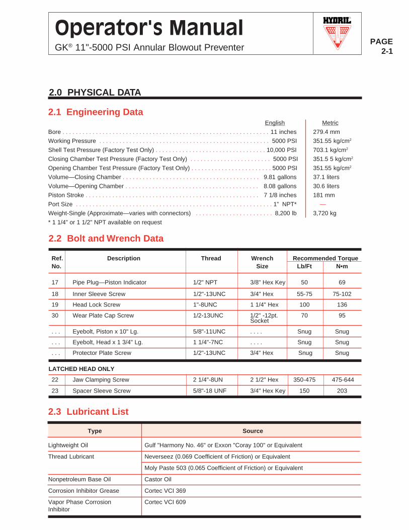
2.0 PHYSICAL DATA
2.1 Engineering DataEnglish Metric
Bore . . . . . . . . . . . . . . . . . . . . . . . . . . . . . . . . . . . . . . . . . . . . . . . . . . . . . . . . . . . . . . 11 inches 279.4 mm
Working Pressure . . . . . . . . . . . . . . . . . . . . . . . . . . . . . . . . . . . . . . . . . . . . . . . . . . . 5000 PSI 351.55 kg/cm2
Shell Test Pressure (Factory Test Only) . . . . . . . . . . . . . . . . . . . . . . . . . . . . . . . . . 10,000 PSI 703.1 kg/cm2
Closing Chamber Test Pressure (Factory Test Only) . . . . . . . . . . . . . . . . . . . . . . . . 5000 PSI 351.5 5 kg/cm2
Opening Chamber Test Pressure (Factory Test Only) . . . . . . . . . . . . . . . . . . . . . . . . 5000 PSI 351.55 kg/cm2
Volume—Closing Chamber . . . . . . . . . . . . . . . . . . . . . . . . . . . . . . . . . . . . . . . . . 9.81 gallons 37.1 liters
Volume—Opening Chamber . . . . . . . . . . . . . . . . . . . . . . . . . . . . . . . . . . . . . . . . 8.08 gallons 30.6 liters
Piston Stroke . . . . . . . . . . . . . . . . . . . . . . . . . . . . . . . . . . . . . . . . . . . . . . . . . . . . 7 1/8 inches 181 mm
Port Size . . . . . . . . . . . . . . . . . . . . . . . . . . . . . . . . . . . . . . . . . . . . . . . . . . . . . . . . . . . 1” NPT* —
Weight-Single (Approximate—varies with connectors) . . . . . . . . . . . . . . . . . . . . . . . 8,200 lb 3,720 kg
* 1 1/4" or 1 1/2" NPT available on request
2.3 Lubricant List
2.2 Bolt and Wrench Data
Ref. Description Thread Wrench Recommended TorqueNo. Size Lb/Ft N•m
17 Pipe Plug—Piston Indicator 1/2" NPT 3/8" Hex Key 50 69
18 Inner Sleeve Screw 1/2"-13UNC 3/4" Hex 55-75 75-102
19 Head Lock Screw 1"-8UNC 1 1/4" Hex 100 136
30 Wear Plate Cap Screw 1/2-13UNC 1/2" -12pt. 70 95Socket
. . . Eyebolt, Piston x 10" Lg. 5/8"-11UNC . . . . Snug Snug
. . . Eyebolt, Head x 1 3/4" Lg. 1 1/4"-7NC . . . . Snug Snug
. . . Protector Plate Screw 1/2"-13UNC 3/4" Hex Snug Snug
LATCHED HEAD ONLY
22 Jaw Clamping Screw 2 1/4"-8UN 2 1/2" Hex 350-475 475-644
23 Spacer Sleeve Screw 5/8"-18 UNF 3/4" Hex Key 150 203
Type Source
Lightweight Oil Gulf "Harmony No. 46" or Exxon "Coray 100" or Equivalent
Thread Lubricant Neverseez (0.069 Coefficient of Friction) or Equivalent
Moly Paste 503 (0.065 Coefficient of Friction) or Equivalent
Nonpetroleum Base Oil Castor Oil
Corrosion Inhibitor Grease Cortec VCI 369
Vapor Phase Corrosion Cortec VCI 609Inhibitor
R
PAGE2-2
Operator's ManualGK® 11"-5000 PSI Annular Blowout Preventer
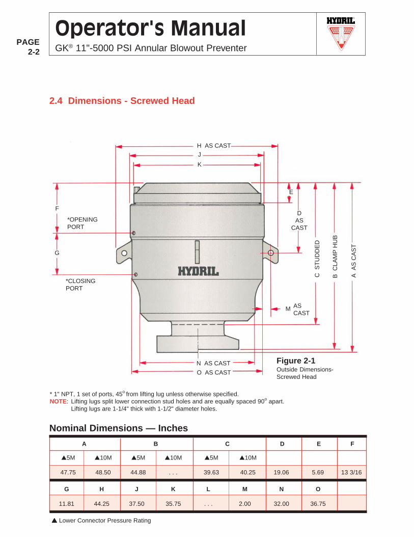
G H J K L M N O
11.81 44.25 37.50 35.75 . . . 2.00 32.00 36.75
▲▲▲▲▲ Lower Connector Pressure Rating
A B C D E F
2.4 Dimensions - Screwed Head
Nominal Dimensions — Inches
H AS CAST
J
K
DAS
CAST
E
C S
TU
DD
ED
B C
LAM
P H
UB
A A
S C
AS
T
M ASCAST
N AS CAST
O AS CAST
G
F
*OPENINGPORT
*CLOSINGPORT
* 1" NPT, 1 set of ports, 45o from lifting lug unless otherwise specified.NOTE: Lifting lugs split lower connection stud holes and are equally spaced 90o apart.
Lifting lugs are 1-1/4" thick with 1-1/2" diameter holes.
▲5M ▲10M ▲5M ▲10M ▲5M ▲10M
47.75 48.50 44.88 . . . 39.63 40.25 19.06 5.69 13 3/16
Figure 2-1Outside Dimensions-Screwed Head
R
PAGE2-3
Operator's ManualGK® 11"-5000 PSI Annular Blowout Preventer
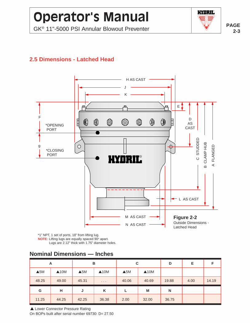
2.5 Dimensions - Latched Head
R
G H J K L M N
11.25 44.25 42.25 36.38 2.00 32.00 36.75
▲▲▲▲▲ Lower Connector Pressure RatingOn BOPs built after serial number 69730: D= 27.50
A B C D E F
Nominal Dimensions — Inches
▲5M ▲10M ▲5M ▲10M ▲5M ▲10M
48.25 49.00 45.31 . . . 40.06 40.69 19.88 4.00 14.19
*OPENING PORT
*CLOSING PORT
F
g
H AS CAST
J
K
E
DAS
CAST
C S
TU
DD
ED
B C
LAM
P H
UB
A F
LAN
GE
D
L AS CAST
M AS CAST
N AS CAST
*1” NPT, 1 set of ports, 18” from lifting lug.NOTE: Lifting lugs are equally spaced 90o apart.
Lugs are 2.12” thick with 1.75” diameter holes.
Figure 2-2Outside Dimensions -Latched Head
R
PAGE2-4
Operator's ManualGK® 11"-5000 PSI Annular Blowout Preventer
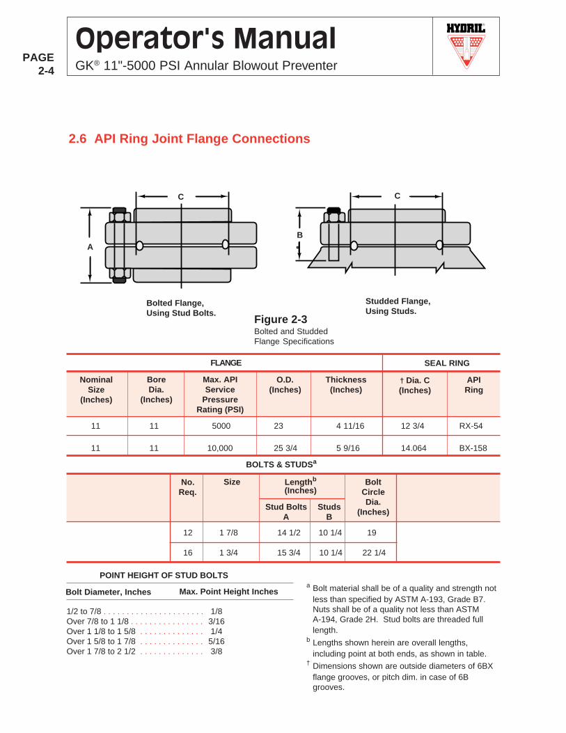
12 1 7/8 14 1/2 10 1/4 19
16 1 3/4 15 3/4 10 1/4 22 1/4
SEAL RINGFLANGE
NominalSize
(Inches)
BoreDia.
(Inches)
BOLTS & STUDSa
O.D.(Inches)
Thickness(Inches)
Max. APIService
PressureRating (PSI)
† Dia. C(Inches)
APIRing
C
A
Bolted Flange,Using Stud Bolts.
Studded Flange,Using Studs.
C
B
2.6 API Ring Joint Flange Connections
Stud BoltsA
BoltCircleDia.
(Inches)
Lengthb
(Inches)SizeNo.
Req.
StudsB
Max. Point Height Inchesa Bolt material shall be of a quality and strength not
less than specified by ASTM A-193, Grade B7.Nuts shall be of a quality not less than ASTMA-194, Grade 2H. Stud bolts are threaded fulllength.
b Lengths shown herein are overall lengths,including point at both ends, as shown in table.
† Dimensions shown are outside diameters of 6BXflange grooves, or pitch dim. in case of 6Bgrooves.
Bolt Diameter, Inches
1/2 to 7/8 . . . . . . . . . . . . . . . . . . . . . . 1/8Over 7/8 to 1 1/8 . . . . . . . . . . . . . . . . 3/16Over 1 1/8 to 1 5/8 . . . . . . . . . . . . . . 1/4Over 1 5/8 to 1 7/8 . . . . . . . . . . . . . . 5/16Over 1 7/8 to 2 1/2 . . . . . . . . . . . . . . 3/8
POINT HEIGHT OF STUD BOLTS
11 11 5000 23 4 11/16 12 3/4 RX-54
11 11 10,000 25 3/4 5 9/16 14.064 BX-158
Figure 2-3Bolted and StuddedFlange Specifications

R
PAGE2-5
Operator's ManualGK® 11"-5000 PSI Annular Blowout Preventer
HUB
2.7 Clamp Hub Connections
BX
HubSize
(Inches)
Seal Ring No.BoreSize
A(Inches)
RatedWorkingPressure
(PSI)
Hub Dimensions (Inches)
11 11 5000 53 . . .
11 11 10,000 . . . 158
B
. . .
3 5/8
C
NOTE: API 16A 1st Edition Nov 1, 1986 Does Not Include Clamps.
16 1/4
16 1/4
RX D J
3 3/4
. . .
15/32
. . .
RX OnlyStandoff
E
. . .
. . .
F
20 13/16
20 13/16
G H
28 1/2
28 1/2
6 3/4
6 3/4
Clamp Dimensions (Inches) ▲
▲ Clamp dimensions may vary from those shown.
J
G
BE
F
AC A
B
EF
G
H H
Figure 2-4Hub Connection Specifications
R
PAGE2-6
Operator's ManualGK® 11"-5000 PSI Annular Blowout Preventer
R
PAGE3-1
Operator's ManualGK® 11"-5000 PSI Annular Blowout Preventer
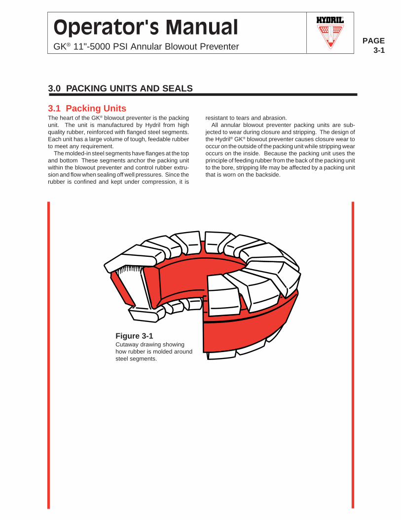
3.1 Packing UnitsThe heart of the GK® blowout preventer is the packingunit. The unit is manufactured by Hydril from highquality rubber, reinforced with flanged steel segments.Each unit has a large volume of tough, feedable rubberto meet any requirement.
The molded-in steel segments have flanges at the topand bottom These segments anchor the packing unitwithin the blowout preventer and control rubber extru-sion and flow when sealing off well pressures. Since therubber is confined and kept under compression, it is
Figure 3-1Cutaway drawing showinghow rubber is molded aroundsteel segments.
resistant to tears and abrasion.All annular blowout preventer packing units are sub-
jected to wear during closure and stripping. The design ofthe Hydril® GK® blowout preventer causes closure wear tooccur on the outside of the packing unit while stripping wearoccurs on the inside. Because the packing unit uses theprinciple of feeding rubber from the back of the packing unitto the bore, stripping life may be affected by a packing unitthat is worn on the backside.
3.0 PACKING UNITS AND SEALS
R
PAGE3-2
Operator's ManualGK® 11"-5000 PSI Annular Blowout Preventer
3.1.1 Packing Unit SelectionBecause of the importance of the packing unit to theoperation of the blowout preventer and to the safety of thecrew and rig, only genuine Hydril® packing units should beused as replacements for original equipment. All Hydril®
packing units are tested to full rated pressure inside a testblowout preventer as part of standard performance testsbefore being furnished to the consumer.
Packing units for Hydril® blowout preventers are manu-factured from compounded natural rubber or nitrile rubber.
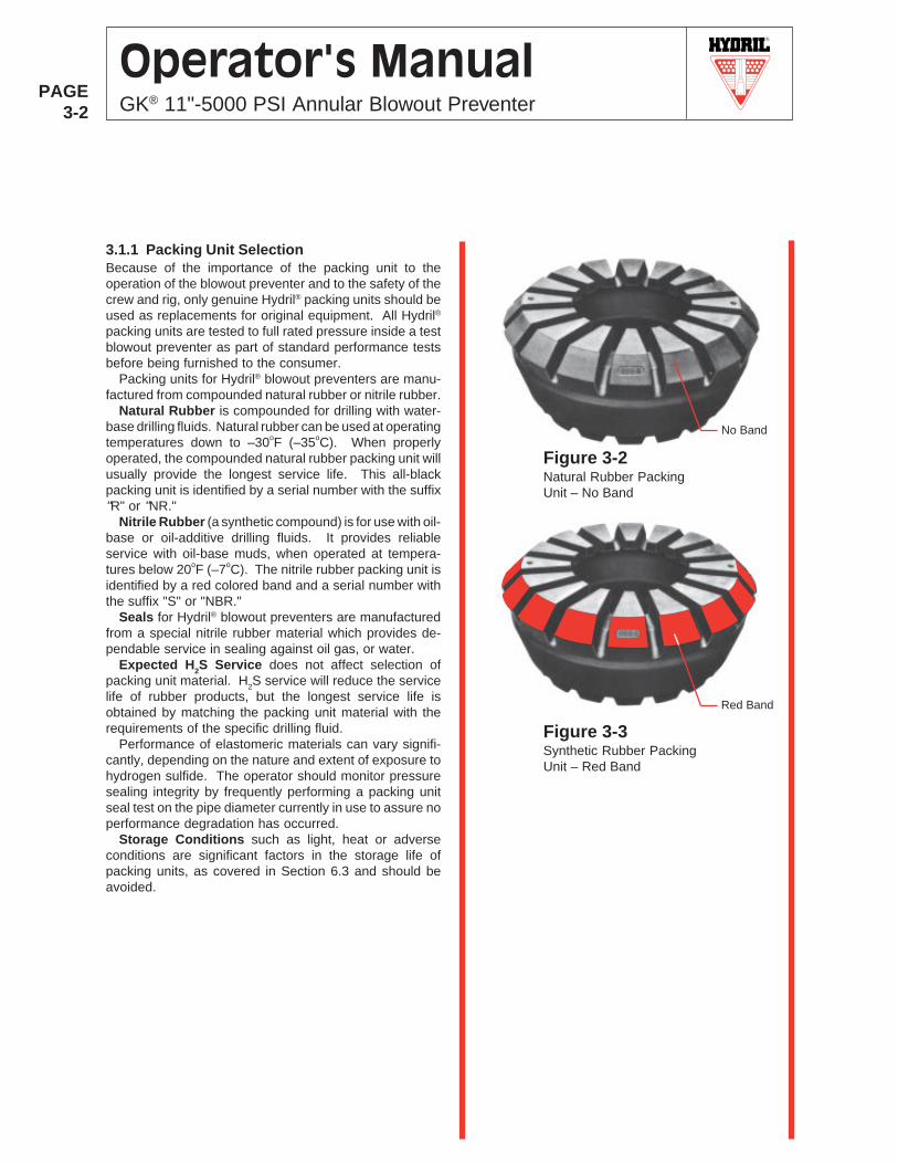
Natural Rubber is compounded for drilling with water-base drilling fluids. Natural rubber can be used at operatingtemperatures down to –30oF (–35oC). When properlyoperated, the compounded natural rubber packing unit willusually provide the longest service life. This all-blackpacking unit is identified by a serial number with the suffix"R" or "NR."
Nitrile Rubber (a synthetic compound) is for use with oil-base or oil-additive drilling fluids. It provides reliableservice with oil-base muds, when operated at tempera-tures below 20oF (–7oC). The nitrile rubber packing unit isidentified by a red colored band and a serial number withthe suffix "S" or "NBR."
Seals for Hydril® blowout preventers are manufacturedfrom a special nitrile rubber material which provides de-pendable service in sealing against oil gas, or water.
Expected H2S Service does not affect selection ofpacking unit material. H2S service will reduce the servicelife of rubber products, but the longest service life isobtained by matching the packing unit material with therequirements of the specific drilling fluid.
Performance of elastomeric materials can vary signifi-cantly, depending on the nature and extent of exposure tohydrogen sulfide. The operator should monitor pressuresealing integrity by frequently performing a packing unitseal test on the pipe diameter currently in use to assure noperformance degradation has occurred.
Storage Conditions such as light, heat or adverseconditions are significant factors in the storage life ofpacking units, as covered in Section 6.3 and should beavoided.
Figure 3-2Natural Rubber PackingUnit – No Band
Figure 3-3Synthetic Rubber PackingUnit – Red Band
Red Band
No Band
R
PAGE3-3
Operator's ManualGK® 11"-5000 PSI Annular Blowout Preventer
OPENING TORQUE
Figure 3-4
Figure 3-5
Figure 3-6
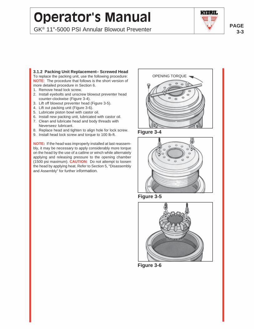
3.1.2 Packing Unit Replacement– Screwed HeadTo replace the packing unit, use the following procedure:NOTE: The procedure that follows is the short version ofmore detailed procedure in Section 6.1. Remove head lock screw.2. Install eyebolts and unscrew blowout preventer head
counter-clockwise (Figure 3-4).3. Lift off blowout preventer head (Figure 3-5).4. Lift out packing unit (Figure 3-6).5. Lubricate piston bowl with castor oil.6. Install new packing unit, lubricated with castor oil.7. Clean and lubricate head and body threads with
Neverseez lubricant.8. Replace head and tighten to align hole for lock screw.9. Install head lock screw and torque to 100 lb-ft.
NOTE: If the head was improperly installed at last reassem-bly, it may be necessary to apply considerably more torqueon the head by the use of a catline or winch while alternatelyapplying and releasing pressure to the opening chamber(1500 psi maximum). CAUTION: Do not attempt to loosenthe head by applying heat. Refer to Section 5, “Disassemblyand Assembly” for further information.
R
PAGE3-4
Operator's ManualGK® 11"-5000 PSI Annular Blowout Preventer
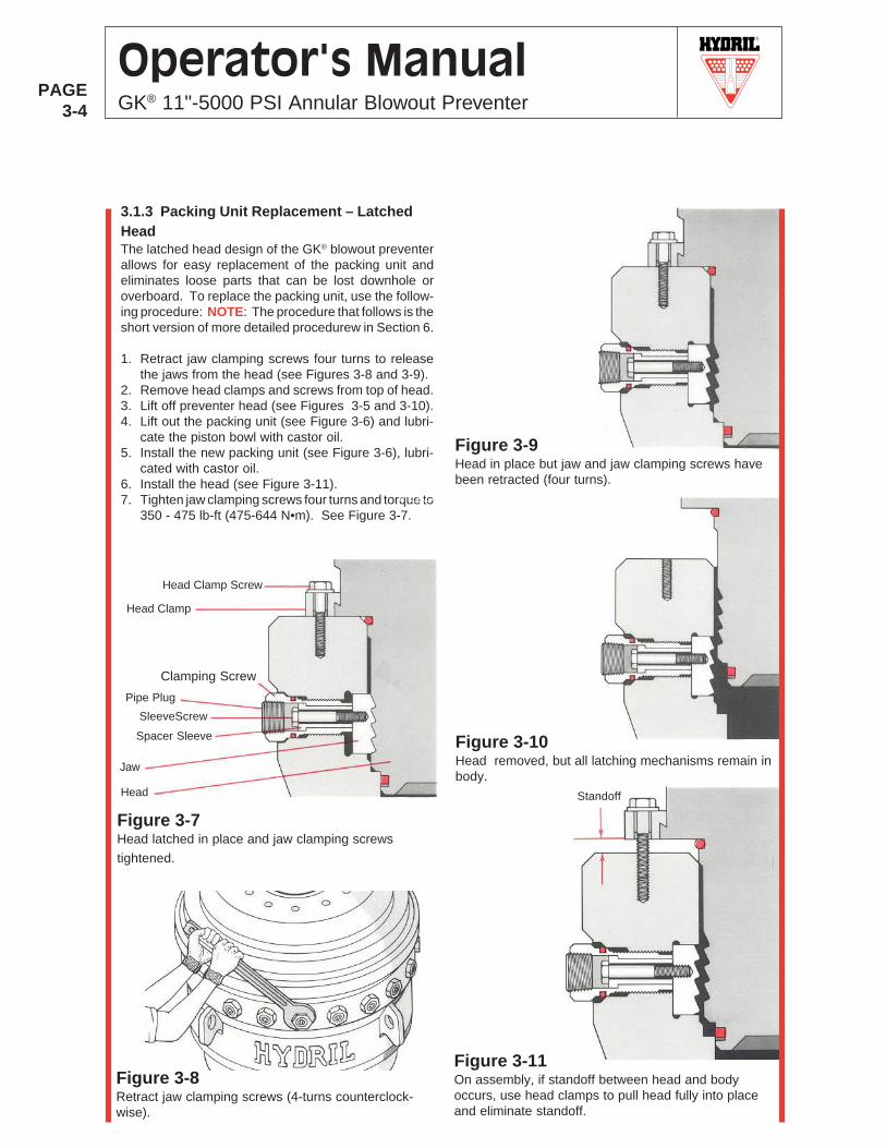
3.1.3 Packing Unit Replacement – LatchedHeadThe latched head design of the GK® blowout preventerallows for easy replacement of the packing unit andeliminates loose parts that can be lost downhole oroverboard. To replace the packing unit, use the follow-ing procedure: NOTE: The procedure that follows is theshort version of more detailed procedurew in Section 6.
1. Retract jaw clamping screws four turns to releasethe jaws from the head (see Figures 3-8 and 3-9).
2. Remove head clamps and screws from top of head.3. Lift off preventer head (see Figures 3-5 and 3-10).4. Lift out the packing unit (see Figure 3-6) and lubri-
cate the piston bowl with castor oil.5. Install the new packing unit (see Figure 3-6), lubri-
cated with castor oil.6. Install the head (see Figure 3-11).7. Tighten jaw clamping screws four turns and torque to
350 - 475 lb-ft (475-644 N•m). See Figure 3-7.
Figure 3-7Head latched in place and jaw clamping screws
tightened.
HEAD
Figure 3-9Head in place but jaw and jaw clamping screws havebeen retracted (four turns).
Figure 3-10Head removed, but all latching mechanisms remain inbody.
Figure 3-8Retract jaw clamping screws (4-turns counterclock-wise).
Figure 3-11On assembly, if standoff between head and bodyoccurs, use head clamps to pull head fully into placeand eliminate standoff.
Standoff
Clamping Screw
SleeveScrew
Head Clamp Screw
Head Clamp
Pipe Plug
Spacer Sleeve
Jaw
Head
R
PAGE3-5
Operator's ManualGK® 11"-5000 PSI Annular Blowout Preventer
DYNAMIC SEALS STATIC SEALS
DOUBLE U-SEALcross-sectionwithnonextrusionrings
U-SEALcross-section
O-RINGcross-section
SQUARE RINGcross-section
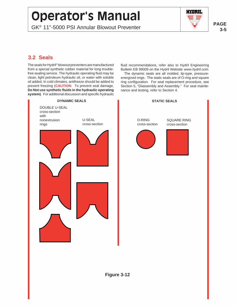
The seals for Hydril® blowout preventers are manufacturedfrom a special synthetic rubber material for long trouble-free sealing service. The hydraulic operating fluid may beclean, light petroleum hydraulic oil, or water with solubleoil added. In cold climates, antifreeze should be added toprevent freezing (CAUTION: To prevent seal damage,Do Not use synthetic fluids in the hydraulic operatingsystem). For additional discussion and specific hydraulic
Figure 3-12
3.2 Sealsfluid recommendations, refer also to Hydril EngineeringBulletin EB 99009 on the Hydril Website www.hydril.com.
The dynamic seals are all molded, lip-type, pressure-energized rings. The static seals are of O-ring and squarering configuration. For seal replacement procedure, seeSection 5, “Diassembly and Assembly.” For seal mainte-nance and testing, refer to Section 4.
R
PAGE3-6
Operator's ManualGK® 11"-5000 PSI Annular Blowout Preventer
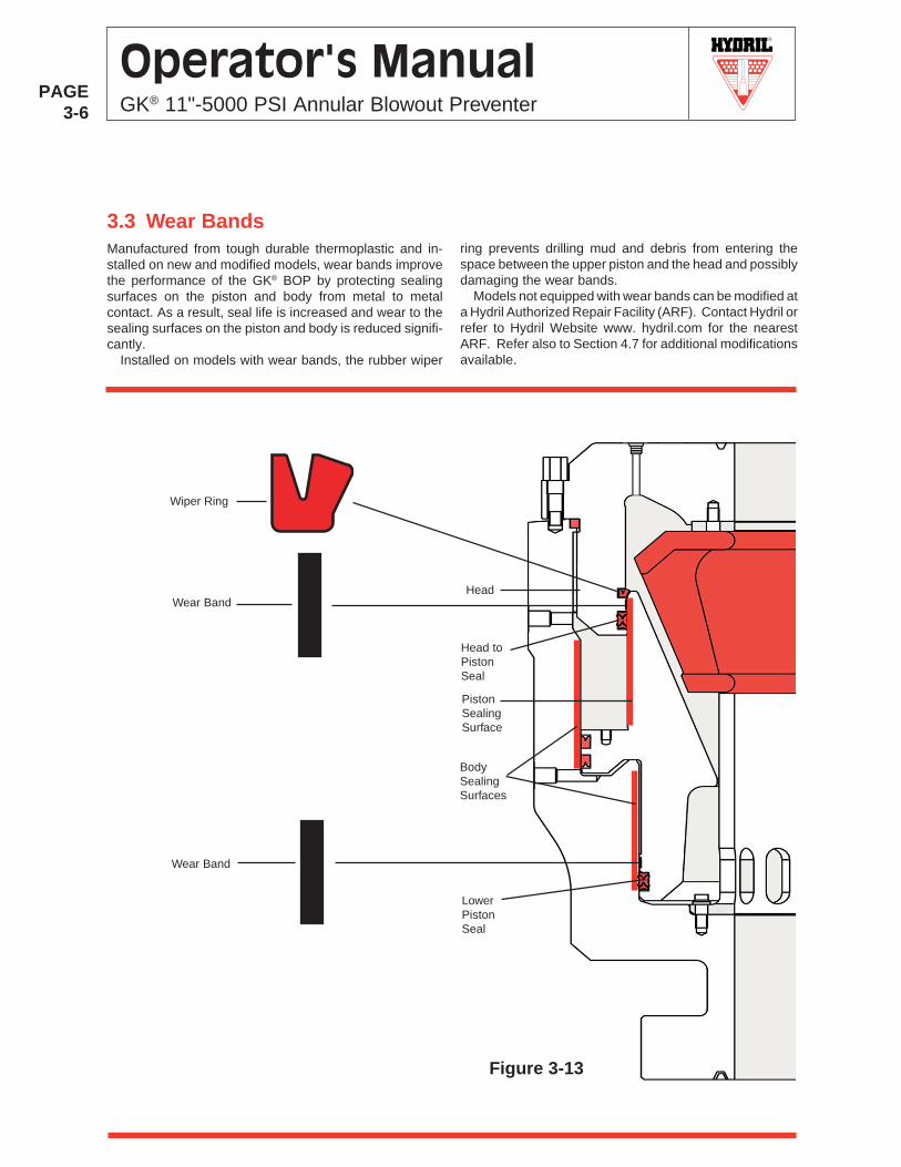
Manufactured from tough durable thermoplastic and in-stalled on new and modified models, wear bands improvethe performance of the GK® BOP by protecting sealingsurfaces on the piston and body from metal to metalcontact. As a result, seal life is increased and wear to thesealing surfaces on the piston and body is reduced signifi-cantly.
Installed on models with wear bands, the rubber wiper
Figure 3-13
3.3 Wear Bandsring prevents drilling mud and debris from entering thespace between the upper piston and the head and possiblydamaging the wear bands.
Models not equipped with wear bands can be modified ata Hydril Authorized Repair Facility (ARF). Contact Hydril orrefer to Hydril Website www. hydril.com for the nearestARF. Refer also to Section 4.7 for additional modificationsavailable.
Head
PistonSealingSurface
BodySealingSurfaces
LowerPistonSeal
Wiper Ring
Wear Band
Wear Band
Head toPistonSeal
R
PAGE4-1
Operator's ManualGK® 11"-5000 PSI Annular Blowout Preventer
4.0 MAINTENANCE AND TESTING
WARNING: HYDRIL IS NOT RESPONSIBLE FORANY ALTERATIONS, MODIFICATIONS OR RE-PAIRS TO THE BLOWOUT PREVENTER (BOP),ITS INTERCONNECTS AND COMPONENTS, UN-LESS PERFORMED WITH HYDRIL SUPPLIEDPARTS AND THE WORK PERFORMED BY AHYDRIL AUTHORIZED REPRESENTATIVE. AL-TERATIONS, MODIFICATIONS, OR REPAIRS PER-FORMED OTHERWISE MAY RESULT IN DAMAGETO THE BOP OR FAILURE OF THE BOP TO OPER-ATE AS DESIGNED AND MAY RESULT IN SERI-OUS PROPERTY DAMAGE, PERSONAL INJURYOR DEATH. UNAUTHORIZED ALTERATIONS,MODIFICATIONS, REPAIRS OR USE OF PARTSOTHER THAN THOSE SUPPLIED BY HYDRIL WILLVOID THE STANDARD WARRANTY OF THE BOPAS OUTLINED IN THE TERMS AND CONDITIONSAGREEMENT.
WARNING: BEFORE THE INITIAL START UP, ORPRIOR TO POST REPAIR START UPS, VERIFYCONTAMINANTS, DEBRIS, AND OTHER FOREIGNMATERIALS HAVE BEEN FLUSHED FROM THE
FLUID SUPPLY LINES. FAILURE TO DO SO MAYRESULT IN DAMAGE TO THE BOP OR FAILUREOF THE BOP TO OPERATE AS DESIGNED ANDMAY RESULT IN SERIOUS PROPERTY DAMAGE,PERSONAL INJURY OR DEATH.
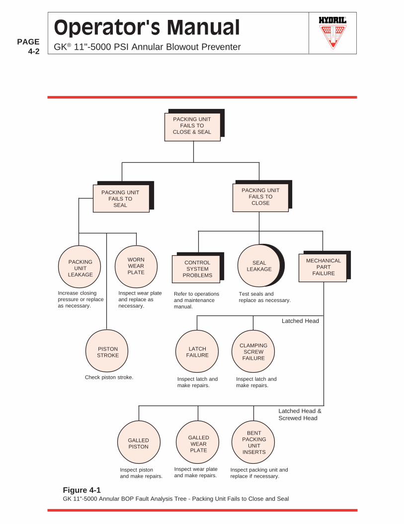
4.1 TroubleshootingTroubleshooting the annular BOP is provided in the form ofa fault analysis tree. If the packing unit fails to close and
seal, refer to Figure 4-1.
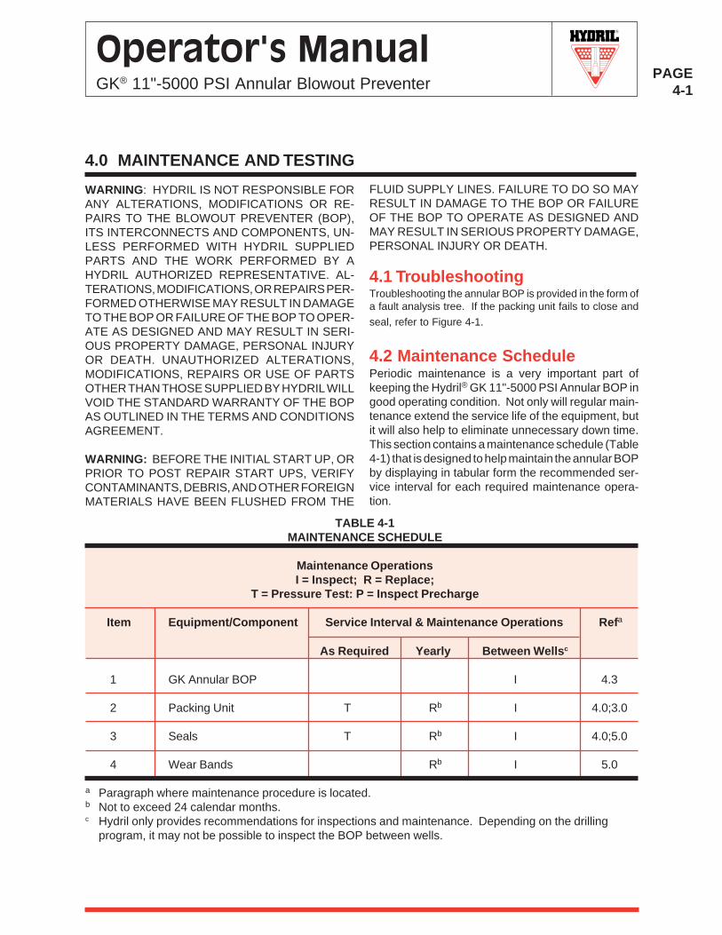
4.2 Maintenance SchedulePeriodic maintenance is a very important part ofkeeping the Hydril® GK 11"-5000 PSI Annular BOP ingood operating condition. Not only will regular main-tenance extend the service life of the equipment, butit will also help to eliminate unnecessary down time.This section contains a maintenance schedule (Table4-1) that is designed to help maintain the annular BOPby displaying in tabular form the recommended ser-vice interval for each required maintenance opera-tion.
a Paragraph where maintenance procedure is located.b Not to exceed 24 calendar months.c Hydril only provides recommendations for inspections and maintenance. Depending on the drilling
program, it may not be possible to inspect the BOP between wells.
TABLE 4-1MAINTENANCE SCHEDULE
Maintenance OperationsI = Inspect; R = Replace;
T = Pressure Test: P = Inspect Precharge
Item Equipment/Component Service Interval & Maintenance Operations Refa
As Required Yearly Between Wellsc
1 GK Annular BOP I 4.3
2 Packing Unit T Rb I 4.0;3.0
3 Seals T Rb I 4.0;5.0
4 Wear Bands Rb I 5.0
R
PAGE4-2
Operator's ManualGK® 11"-5000 PSI Annular Blowout Preventer
Figure 4-1GK 11"-5000 Annular BOP Fault Analysis Tree - Packing Unit Fails to Close and Seal
MECHANICALPART
FAILURE
CONTROLSYSTEM
PROBLEMS
Inspect latch andmake repairs.
Refer to operationsand maintenancemanual.
Test seals andreplace as necessary.
SEALLEAKAGE
CLAMPINGSCREWFAILURE
LATCHFAILURE
PACKING UNITFAILS TOCLOSE
PACKING UNITFAILS TO
CLOSE & SEAL
PACKING UNITFAILS TO
SEAL
Inspect latch andmake repairs.
Inspect packing unit andreplace if necessary.
Inspect pistonand make repairs.
Inspect wear plateand make repairs.
GALLEDPISTON
BENTPACKING
UNITINSERTS
GALLEDWEARPLATE
Latched Head
Latched Head &Screwed Head
PACKINGUNIT
LEAKAGE
Increase closingpressure or replaceas necessary.
WORNWEARPLATE
Inspect wear plateand replace asnecessary.
PISTONSTROKE
Check piston stroke.
R
PAGE4-3
Operator's ManualGK® 11"-5000 PSI Annular Blowout Preventer
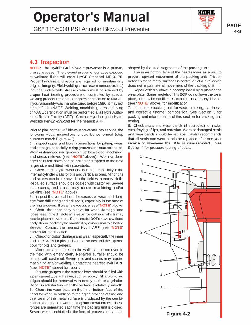
4.3 InspectionNOTE: The Hydril® GK® blowout preventer is a primarypressure vessel. The blowout preventer surfaces exposedto wellbore fluids will meet NACE Standard MR-01-75.Proper handling and repair are required to maintain anyoriginal integrity. Field welding is not recommended as it, 1)induces undesirable stresses which must be relieved byproper heat treating procedure or controlled by specialwelding procedures and 2) negates certification to NACE .If your assembly was manufactured before 1980, it may notbe certified to NACE. Welding, machining, stress relievingor NACE certification must be performed at a Hydril Autho-rized Repair Facility (ARF). Contact Hydril or go to HydrilWebsite www.hydril.com for the nearest ARF.
Prior to placing the GK® blowout preventer into service, thefollowing visual inspections should be performed (stepnumbers match Figure 4-2):1. Inspect upper and lower connections for pitting, wear,and damage, especially in ring grooves and stud bolt holes.Worn or damaged ring grooves must be welded, machined,and stress relieved (see “NOTE” above). Worn or dam-aged stud bolt holes can be drilled and tapped to the nextlarger size and fitted with step-studs.2. Check the body for wear and damage, especially in theinternal cylinder walls for pits and vertical scores. Minor pitsand scores can be removed in the field with emery cloth.Repaired surface should be coated with castor oil. Severepits, scores, and cracks may require machining and/orwelding (see “NOTE” above).3. Inspect the vertical bore for excessive wear and dam-age from drill string and drill tools, especially in the area ofthe ring grooves. If wear is excessive, see “NOTE” above.4. Check the inner body sleeve for wear, damage, andlooseness. Check slots in sleeve for cuttings which mayrestrict piston movement. Some model BOPs have a weldedbody sleeve and may be modified by conversion to a boltedsleeve. Contact the nearest Hydril ARF (see “NOTE”above) for modification.5. Check for piston damage and wear, especially the innerand outer walls for pits and vertical scores and the taperedbowl for pits and gouges.
Minor pits and scores on the walls can be removed inthe field with emery cloth. Repaired surface should becoated with castor oil. Severe pits and scores may requiremachining and/or welding. Contact the nearest Hydril ARF(see “NOTE” above) for repair.
Pits and gouges in the tapered bowl should be filled witha permanent type adhesive, such as epoxy. Sharp or rollededges should be removed with emery cloth or a grinder.Repair is satisfactory when the surface is relatively smooth.6. Check the wear plate on the inner bottom face of thehead for wear. In addition to the aging process of time anduse, wear of this metal surface is produced by the combi-nation of vertical (upward thrust) and lateral forces. Theseforces are generated each time the packing unit is closed.Severe wear is exhibited in the form of grooves or channels
shaped by the steel segments of the packing unit.The inner bottom face of the head serves as a wall to
prevent upward movement of the packing unit. Frictionbetween these metal surfaces is controlled at a level whichdoes not impair lateral movement of the packing unit.
Repair of this surface is accomplished by replacing thewear plate. Some models of this BOP do not have the wearplate, but may be modified. Contact the nearest Hydril ARF(see “NOTE” above) for modification.7. Inspect the packing unit for wear, cracking, hardness,and correct elastomer composition. See Section 3 forpacking unit information and this section for packing unittesting.8. Check seals and wear bands (if equipped) for nicks,cuts, fraying of lips, and abrasion. Worn or damaged sealsand wear bands should be replaced. Hydril recommendsthat all seals and wear bands be replaced after one yearservice or whenever the BOP is disassembled. SeeSection 4 for pressure testing of seals.
1
3
8
8
3
1
8
6
5
2
4
Figure 4-2
7
8
R
PAGE4-4
Operator's ManualGK® 11"-5000 PSI Annular Blowout Preventer
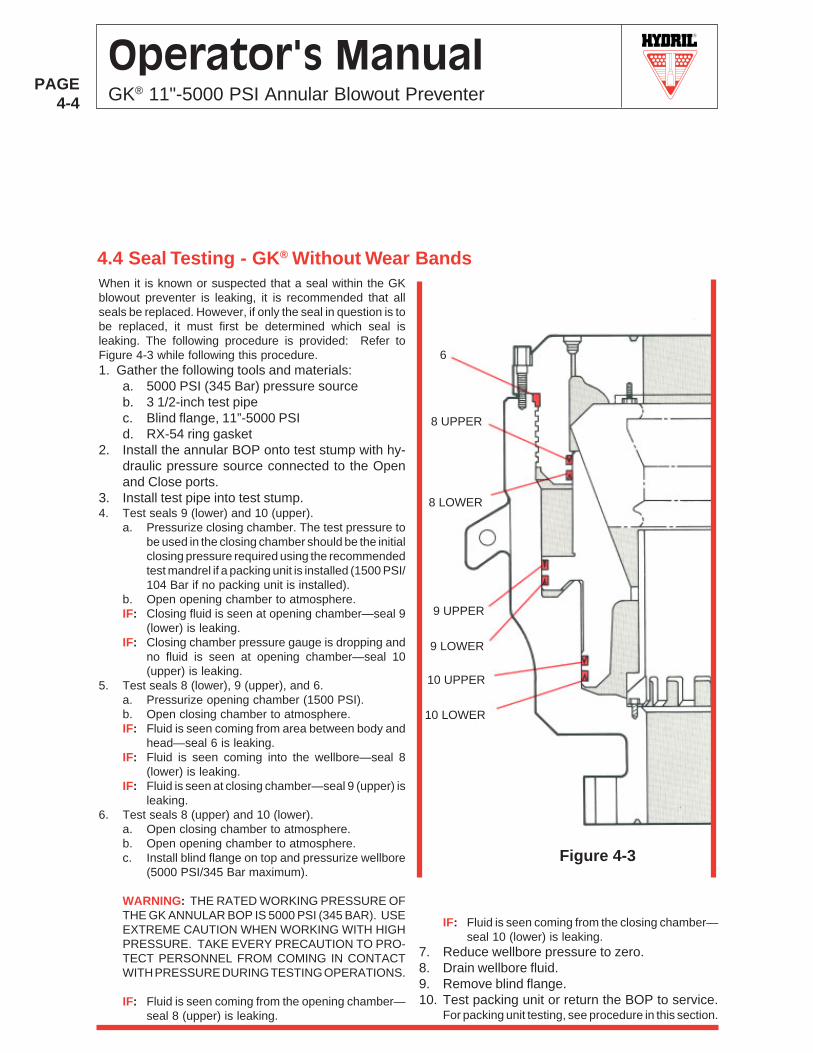
When it is known or suspected that a seal within the GKblowout preventer is leaking, it is recommended that allseals be replaced. However, if only the seal in question is tobe replaced, it must first be determined which seal isleaking. The following procedure is provided: Refer toFigure 4-3 while following this procedure.1. Gather the following tools and materials:
a. 5000 PSI (345 Bar) pressure sourceb. 3 1/2-inch test pipec. Blind flange, 11”-5000 PSId. RX-54 ring gasket
2. Install the annular BOP onto test stump with hy-draulic pressure source connected to the Openand Close ports.
3. Install test pipe into test stump.4. Test seals 9 (lower) and 10 (upper).
a. Pressurize closing chamber. The test pressure tobe used in the closing chamber should be the initialclosing pressure required using the recommendedtest mandrel if a packing unit is installed (1500 PSI/104 Bar if no packing unit is installed).
b. Open opening chamber to atmosphere.IF: Closing fluid is seen at opening chamber—seal 9
(lower) is leaking.IF: Closing chamber pressure gauge is dropping and
no fluid is seen at opening chamber—seal 10(upper) is leaking.
5. Test seals 8 (lower), 9 (upper), and 6.a. Pressurize opening chamber (1500 PSI).b. Open closing chamber to atmosphere.IF: Fluid is seen coming from area between body and
head—seal 6 is leaking.IF: Fluid is seen coming into the wellbore—seal 8
(lower) is leaking.IF: Fluid is seen at closing chamber—seal 9 (upper) is
leaking.6. Test seals 8 (upper) and 10 (lower).
a. Open closing chamber to atmosphere.b. Open opening chamber to atmosphere.c. Install blind flange on top and pressurize wellbore
(5000 PSI/345 Bar maximum).
WARNING: THE RATED WORKING PRESSURE OFTHE GK ANNULAR BOP IS 5000 PSI (345 BAR). USEEXTREME CAUTION WHEN WORKING WITH HIGHPRESSURE. TAKE EVERY PRECAUTION TO PRO-TECT PERSONNEL FROM COMING IN CONTACTWITH PRESSURE DURING TESTING OPERATIONS.
IF: Fluid is seen coming from the opening chamber—seal 8 (upper) is leaking.
Figure 4-3
6
8 UPPER
8 LOWER
9 UPPER
9 LOWER
10 UPPER
10 LOWER
4.4 Seal Testing - GK® Without Wear Bands
IF: Fluid is seen coming from the closing chamber—seal 10 (lower) is leaking.
7. Reduce wellbore pressure to zero.8. Drain wellbore fluid.9. Remove blind flange.10. Test packing unit or return the BOP to service.
For packing unit testing, see procedure in this section.
R
PAGE4-5
Operator's ManualGK® 11"-5000 PSI Annular Blowout Preventer
Figure 4-4
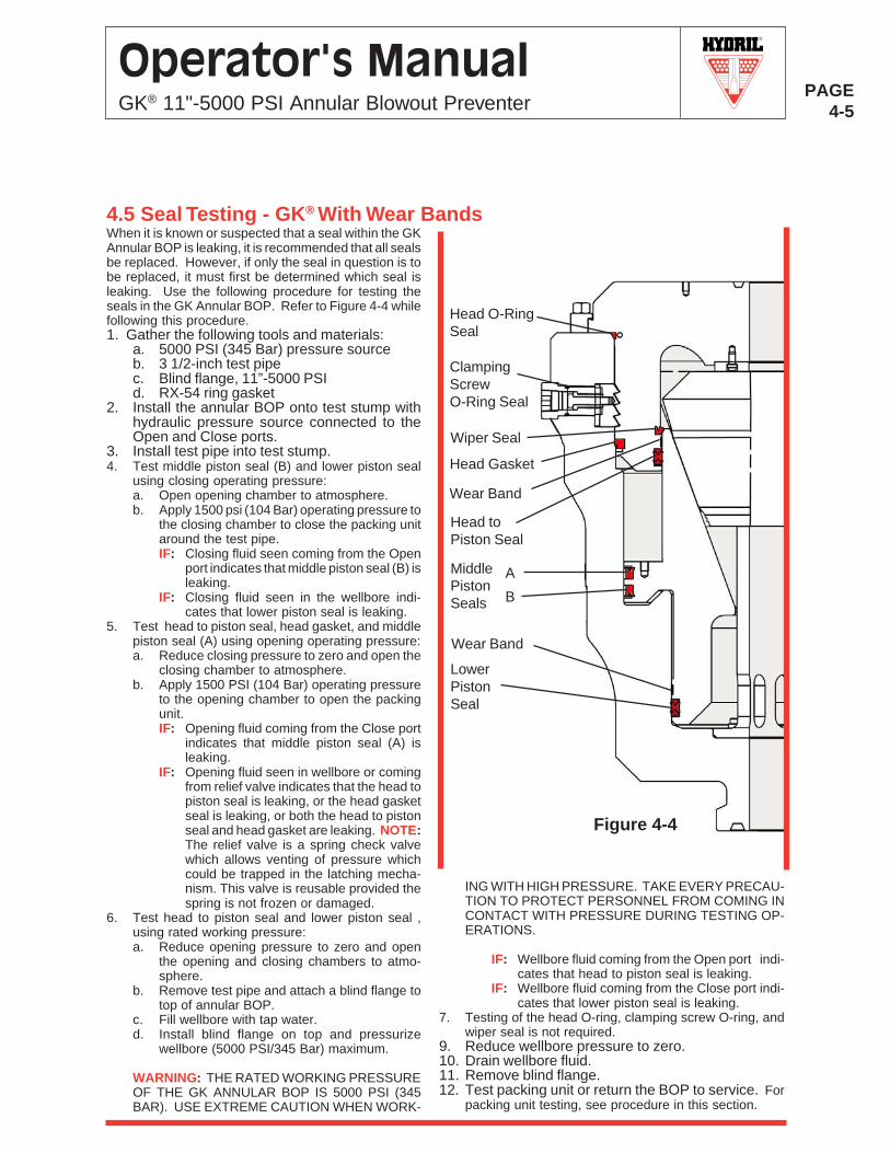
4.5 Seal Testing - GK® With Wear BandsWhen it is known or suspected that a seal within the GKAnnular BOP is leaking, it is recommended that all sealsbe replaced. However, if only the seal in question is tobe replaced, it must first be determined which seal isleaking. Use the following procedure for testing theseals in the GK Annular BOP. Refer to Figure 4-4 whilefollowing this procedure.1. Gather the following tools and materials:
a. 5000 PSI (345 Bar) pressure sourceb. 3 1/2-inch test pipec. Blind flange, 11”-5000 PSId. RX-54 ring gasket
2. Install the annular BOP onto test stump withhydraulic pressure source connected to theOpen and Close ports.
3. Install test pipe into test stump.4. Test middle piston seal (B) and lower piston seal
using closing operating pressure:a. Open opening chamber to atmosphere.b. Apply 1500 psi (104 Bar) operating pressure to
the closing chamber to close the packing unitaround the test pipe.IF: Closing fluid seen coming from the Open
port indicates that middle piston seal (B) isleaking.
IF: Closing fluid seen in the wellbore indi-cates that lower piston seal is leaking.
5. Test head to piston seal, head gasket, and middlepiston seal (A) using opening operating pressure:a. Reduce closing pressure to zero and open the
closing chamber to atmosphere.b. Apply 1500 PSI (104 Bar) operating pressure
to the opening chamber to open the packingunit.IF: Opening fluid coming from the Close port
indicates that middle piston seal (A) isleaking.
IF: Opening fluid seen in wellbore or comingfrom relief valve indicates that the head topiston seal is leaking, or the head gasketseal is leaking, or both the head to pistonseal and head gasket are leaking. NOTE:The relief valve is a spring check valvewhich allows venting of pressure whichcould be trapped in the latching mecha-nism. This valve is reusable provided thespring is not frozen or damaged.
6. Test head to piston seal and lower piston seal ,using rated working pressure:a. Reduce opening pressure to zero and open
the opening and closing chambers to atmo-sphere.
b. Remove test pipe and attach a blind flange totop of annular BOP.
c. Fill wellbore with tap water.d. Install blind flange on top and pressurize
wellbore (5000 PSI/345 Bar) maximum.
WARNING: THE RATED WORKING PRESSUREOF THE GK ANNULAR BOP IS 5000 PSI (345BAR). USE EXTREME CAUTION WHEN WORK-
ING WITH HIGH PRESSURE. TAKE EVERY PRECAU-TION TO PROTECT PERSONNEL FROM COMING INCONTACT WITH PRESSURE DURING TESTING OP-ERATIONS.
IF: Wellbore fluid coming from the Open port indi-cates that head to piston seal is leaking.
IF: Wellbore fluid coming from the Close port indi-cates that lower piston seal is leaking.
7. Testing of the head O-ring, clamping screw O-ring, andwiper seal is not required.
9. Reduce wellbore pressure to zero.10. Drain wellbore fluid.11. Remove blind flange.12. Test packing unit or return the BOP to service. For
packing unit testing, see procedure in this section.
Head toPiston Seal
Head Gasket
MiddlePistonSeals
LowerPistonSeal
Head O-RingSeal
ClampingScrewO-Ring Seal
Wiper Seal
A
B
Wear Band
Wear Band
R
PAGE4-6
Operator's ManualGK® 11"-5000 PSI Annular Blowout Preventer
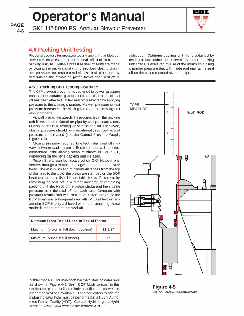
4.6.1 Packing Unit Testing—SurfaceThe GK® blowout preventer is designed to be well pressureassisted in maintaining packing unit seal off once initial sealoff has been effected. Initial seal off is effected by applyingpressure to the closing chamber. As well pressure or testpressure increases, the closing force on the packing unitalso increases.
As well pressure exceeds the required level, the packingunit is maintained closed on pipe by well pressure alone.During routine BOP testing, once initial seal off is achieved,closing pressure should be proportionally reduced as wellpressure is increased (see the Control Pressure Graph,Figure 1-9).
Closing pressure required to effect initial seal off mayvary between packing units. Begin the test with the rec-ommended initial closing pressure shown in Figure 1-8,depending on the style packing unit installed.
Piston Stroke can be measured on GK® blowout pre-venters through a vertical passage* in the top of the BOPhead. The maximum and minimum distances from the topof the head to the top of the piston are stamped on the BOPhead and are also listed in the table below. Piston strokeremaining at seal off is a direct indicator of remainingpacking unit life. Record the piston stroke and the closingpressure at initial seal off for each test. Compare withprevious results and with maximum piston stroke for theBOP to ensure subsequent seal offs. A valid test on anyannular BOP is only achieved when the remaining pistonstroke is measured at test seal off.
Distance From Top of Head to Top of Piston
Maximum (piston in full down position) 11-1/8"
Minimum (piston at full stroke) 4"
4.6 Packing Unit TestingProper procedure for pressure testing any annular blowoutpreventer ensures subsequent seal off and maximumpacking unit life. Reliable pressure seal off tests are madeby closing the packing unit with prescribed closing cham-ber pressure on recommended size test pipe and bydetermining the remaining piston travel after seal off is
achieved. Optimum packing unit life is obtained bytesting at low rubber stress levels. Minimum packingunit stress is achieved by use of the minimum closingchamber pressure that will initiate and maintain a sealoff on the recommended size test pipe.
* Older model BOPs may not have the piston indicator holeas shown in Figure 4-5. See “BOP Modifications” in thissection for piston indicator hole modification as well asother modifications available. Themodification to add thepiston indicator hole must be performed at a Hydril Autho-rized Repair Facility (ARF). Contact Hydril or go to HydrilWebsite www.hydril.com for the nearest ARF.
Figure 4-5Piston Stroke Measurement
TAPEMEASURE
3
2
1
5/16" ROD
R
PAGE4-7
Operator's ManualGK® 11"-5000 PSI Annular Blowout Preventer
4.7 BOP Modifications
Older model BOPs without piston indicator holes, wearplates, bolted inner sleeves, or wear bands can be modi-fied at a Hydril Authorized Repair Facility (ARF). ContactHydril or visit Hydril Website www.hydril.com for the near-est ARF.
R
PAGE4-8
Operator's ManualGK® 11"-5000 PSI Annular Blowout Preventer
R
PAGE5-1
Operator's ManualGK® 11"-5000 PSI Annular Blowout Preventer
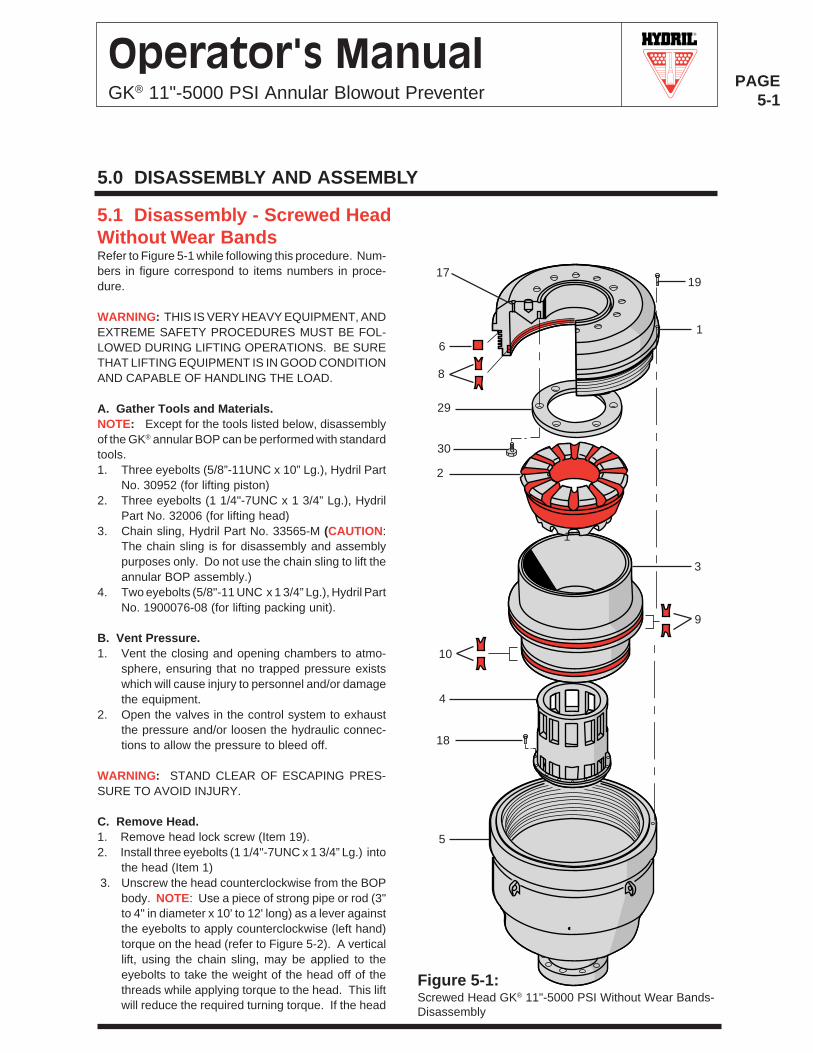
Figure 5-1:Screwed Head GK® 11"-5000 PSI Without Wear Bands-Disassembly
1
3
1
9
1917
6
8
29
30
2
10
4
18
5
5.1 Disassembly - Screwed HeadWithout Wear BandsRefer to Figure 5-1 while following this procedure. Num-bers in figure correspond to items numbers in proce-dure.
WARNING: THIS IS VERY HEAVY EQUIPMENT, ANDEXTREME SAFETY PROCEDURES MUST BE FOL-LOWED DURING LIFTING OPERATIONS. BE SURETHAT LIFTING EQUIPMENT IS IN GOOD CONDITIONAND CAPABLE OF HANDLING THE LOAD.
A. Gather Tools and Materials.NOTE: Except for the tools listed below, disassemblyof the GK® annular BOP can be performed with standardtools.1. Three eyebolts (5/8”-11UNC x 10” Lg.), Hydril Part
No. 30952 (for lifting piston)2. Three eyebolts (1 1/4"-7UNC x 1 3/4” Lg.), Hydril
Part No. 32006 (for lifting head)3. Chain sling, Hydril Part No. 33565-M (CAUTION:
The chain sling is for disassembly and assemblypurposes only. Do not use the chain sling to lift theannular BOP assembly.)
4. Two eyebolts (5/8"-11 UNC x 1 3/4” Lg.), Hydril PartNo. 1900076-08 (for lifting packing unit).
B. Vent Pressure.1. Vent the closing and opening chambers to atmo-
sphere, ensuring that no trapped pressure existswhich will cause injury to personnel and/or damagethe equipment.
2. Open the valves in the control system to exhaustthe pressure and/or loosen the hydraulic connec-tions to allow the pressure to bleed off.
WARNING: STAND CLEAR OF ESCAPING PRES-SURE TO AVOID INJURY.
C. Remove Head.1. Remove head lock screw (Item 19).2. Install three eyebolts (1 1/4"-7UNC x 1 3/4” Lg.) into
the head (Item 1)3. Unscrew the head counterclockwise from the BOP
body. NOTE: Use a piece of strong pipe or rod (3"to 4" in diameter x 10' to 12' long) as a lever againstthe eyebolts to apply counterclockwise (left hand)torque on the head (refer to Figure 5-2). A verticallift, using the chain sling, may be applied to theeyebolts to take the weight of the head off of thethreads while applying torque to the head. This liftwill reduce the required turning torque. If the head
5.0 DISASSEMBLY AND ASSEMBLY
R
PAGE5-2
Operator's ManualGK® 11"-5000 PSI Annular Blowout Preventer
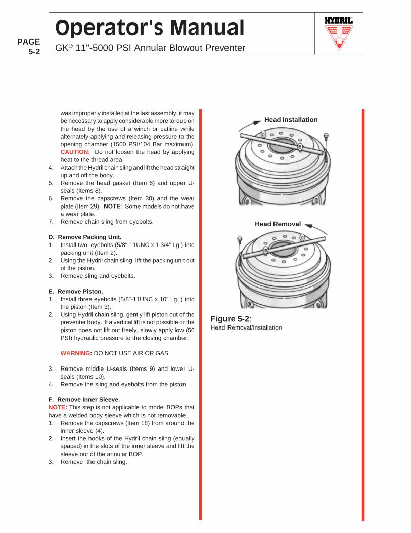
was improperly installed at the last assembly, it maybe necessary to apply considerable more torque onthe head by the use of a winch or catline whilealternately applying and releasing pressure to theopening chamber (1500 PSI/104 Bar maximum).CAUTION: Do not loosen the head by applyingheat to the thread area.
4. Attach the Hydril chain sling and lift the head straightup and off the body.
5. Remove the head gasket (Item 6) and upper U-seals (Items 8).
6. Remove the capscrews (Item 30) and the wearplate (Item 29). NOTE: Some models do not havea wear plate.
7. Remove chain sling from eyebolts.
D. Remove Packing Unit.1. Install two eyebolts (5/8"-11UNC x 1 3/4” Lg.) into
packing unit (Item 2).2. Using the Hydril chain sling, lift the packing unit out
of the piston.3. Remove sling and eyebolts.
E. Remove Piston.1. Install three eyebolts (5/8”-11UNC x 10” Lg. ) into
the piston (Item 3).2. Using Hydril chain sling, gently lift piston out of the
preventer body. If a vertical lift is not possible or thepiston does not lift out freely, slowly apply low (50PSI) hydraulic pressure to the closing chamber.
WARNING: DO NOT USE AIR OR GAS.
3. Remove middle U-seals (Items 9) and lower U-seals (Items 10).
4. Remove the sling and eyebolts from the piston.
F. Remove Inner Sleeve.NOTE: This step is not applicable to model BOPs thathave a welded body sleeve which is not removable.1. Remove the capscrews (Item 18) from around the
inner sleeve (4).2. Insert the hooks of the Hydril chain sling (equally
spaced) in the slots of the inner sleeve and lift thesleeve out of the annular BOP.
3. Remove the chain sling.
Head Installation
Head Removal
Figure 5-2:Head Removal/Installation
R
PAGE5-3
Operator's ManualGK® 11"-5000 PSI Annular Blowout Preventer
Figure 5-3:Screwed Head GK® 11-5000 PSI- Without Wear Bands-Assembly
1
3
1
9
1917
6
8
29
30
2
10
4
18
5
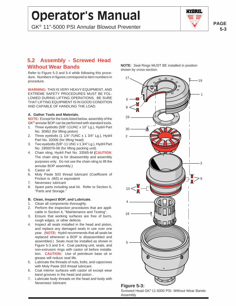
NOTE: Seal Rings MUST BE installed in positionshown by cross-section.
Refer to Figure 5-3 and 5-4 while following this proce-dure. Numbers in figures correspond to item numbers inprocedure.
WARNING: THIS IS VERY HEAVY EQUIPMENT, ANDEXTREME SAFETY PROCEDURES MUST BE FOL-LOWED DURING LIFTING OPERATIONS. BE SURETHAT LIFTING EQUIPMENT IS IN GOOD CONDITIONAND CAPABLE OF HANDLING THE LOAD.
A. Gather Tools and Materials.NOTE: Except for the tools listed below, assembly of theGK® annular BOP can be performed with standard tools.1. Three eyebolts (5/8”-11UNC x 10” Lg.), Hydril Part
No. 30952 (for lifting piston)2. Three eyebolts (1 1/4"-7UNC x 1 3/4” Lg.), Hydril
Part No. 32006 (for lifting head)3. Two eyebolts (5/8"-11 UNC x 1 3/4” Lg.), Hydril Part
No. 1900076-08 (for lifting packing unit)4. Chain sling, Hydril Part No. 33565-M (CAUTION:
The chain sling is for disassembly and assemblypurposes only. Do not use the chain sling to lift theannular BOP assembly.)
5. Castor oil6. Moly Paste 503 thread lubricant (Coefficient of
Friction is .065) or equivalent7. Neverseez lubricant8. Spare parts including seal kit. Refer to Section 6,
"Parts and Storage."
B. Clean, Inspect BOP, and Lubricate.1. Clean all components thoroughly.2. Perform the inspection procedures that are appli-
cable in Section 4, "Maintenance and Testing".3. Ensure that working surfaces are free of burrs,
rough edges, or other defects.4. Inspect all seals installed in the head and piston,
and replace any damaged seals in use over oneyear. (NOTE: Hydril recommends that all seals bereplaced whenever a BOP is disassembled andassembled.) Seals must be installed as shown inFigure 5-3 and 5-4. Coat packing unit, seals, andnon-extrusion rings with castor oil before installa-tion. CAUTION: Use of petroleum base oil orgrease will reduce seal life.
5. Lubricate the threads of nuts, bolts, and capscrewswith Moly Paste 503 thread lubricant.
6. Coat interior surfaces with castor oil except wearband grooves in the head and piston .
7. Lubricate body threads on the head and body withNeverseez lubricant.
5.2 Assembly - Screwed HeadWithout Wear Bands
R
PAGE5-4
Operator's ManualGK® 11"-5000 PSI Annular Blowout Preventer
C. Install Inner Sleeve.NOTE: This step is not applicable for models that havea welded body sleeve .1. Insert hooks of Hydril chain sling (equally spaced)
into slots in inner sleeve (Item 4) and install thesleeve into the bore of the body.
2. Install the capscrews (Item 18) and torque to 150 lb-ft (203 N•m).
3. Remove chain sling.
D. Install Piston.1. Install the lower U-seals (Item 10), on the lower
segment of the piston (Item 3).2. Install the middle U-seals (Items 9) on the upper
segment of the piston.3. Install three eyebolts (5/8”-11UNC x 10” Lg.) into
the piston. Attach the Hydril chain sling to theeyebolts and install the piston over the inner sleeve(Item 4) and into the body. Ensure that the pistonis aligned vertically with the body prior to lowering.Vent Close port. With proper vertical alignment, thepiston will slide its normal full stroke to the bottomof the preventer body. CAUTION: Be careful not todamage the seals during assembly.
4. Remove the chain sling and eyebolts from thepiston.
E. Install Packing Unit.1. Lubricate the bowl of the piston (Item 3) and pack-
ing unit (Item 2) with castor oil. Install two eyebolts(5/8"-11 UNC x 1 3/4” Lg.) into packing unit. UsingHydril chain sling, lift the packing unit and set it intothe bowl of the piston.
2. Remove the chain sling and eyebolts from thepacking unit.
F. Install Head.1. Install the wear plate (Item 29) and capscrews (Item
30) on the inner face of the annular head (Item 1).Torque the capscrews to 50 lb-ft (68 N•m). NOTE:This step is not applicable to models that do nothave a wear plate.
2. Install the head gasket (Item 6) in the seal grooveon the outside diameter of the head, just below themajor diameter.
3. Install the upper U-seals (Item 8) on the insidebottom diameter of the head.
4. Install three eyebolts (1 1/4"-7UNC x 1 3/4” Lg.) intothe head.
5. Lubricate the body threads on the outside diameterof the head and the inside diameter of the body(Item 5) with Neverseez lubricant.
6. Install the head into the body so that the bodythreads on the head engage the threads of thebody. Remove the chain sling.
7. Tighten the head clockwise (right hand) as shown inFigure 5-2, using the pipe or rod from Step C of thedisassembly procedure, until the shoulder on the headengages the body. A vertical lift, using the chain slingattached to the eyebolts, will reduce the weight on thethreads and reduce the required turning torque. Align thehead lock bracket with the hole in the body. Lubricate thelock screw threads (Item 19) with Moly Paste 503 andinstall. Tighten the lock screw using 60 lb-ft (80 N•m)torque.
8. Remove the chain sling and eyebolts from the head.9. Perform seal and packing unit test procedures in Section
4, "Maintenance and Testing."
R
PAGE5-5
Operator's ManualGK® 11"-5000 PSI Annular Blowout Preventer
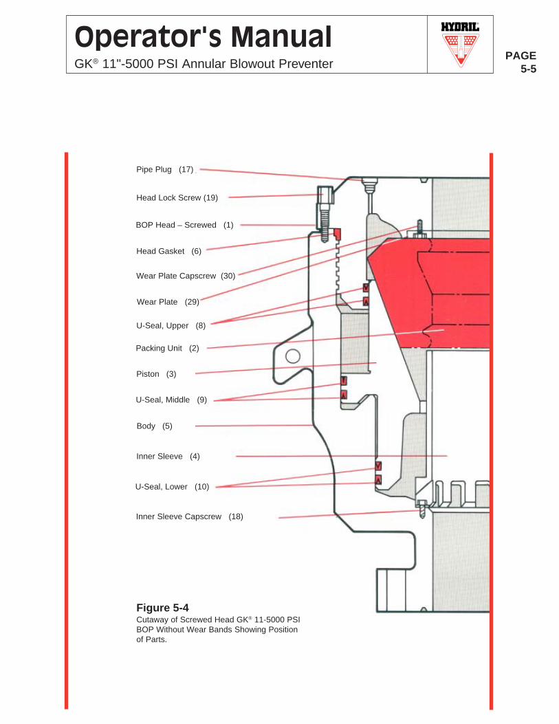
Pipe Plug (17)
BOP Head – Screwed (1)
Wear Plate Capscrew (30)
Head Gasket (6)
Wear Plate (29)
U-Seal, Upper (8)
Packing Unit (2)
Piston (3)
U-Seal, Middle (9)
Body (5)
Inner Sleeve (4)
U-Seal, Lower (10)
Inner Sleeve Capscrew (18)
Figure 5-4Cutaway of Screwed Head GK® 11-5000 PSIBOP Without Wear Bands Showing Positionof Parts.
Head Lock Screw (19)
R
PAGE5-6
Operator's ManualGK® 11"-5000 PSI Annular Blowout Preventer
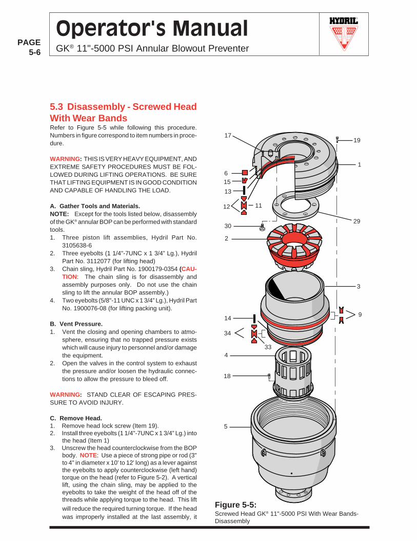
Refer to Figure 5-5 while following this procedure.Numbers in figure correspond to item numbers in proce-dure.
WARNING: THIS IS VERY HEAVY EQUIPMENT, ANDEXTREME SAFETY PROCEDURES MUST BE FOL-LOWED DURING LIFTING OPERATIONS. BE SURETHAT LIFTING EQUIPMENT IS IN GOOD CONDITIONAND CAPABLE OF HANDLING THE LOAD.
A. Gather Tools and Materials.NOTE: Except for the tools listed below, disassemblyof the GK® annular BOP can be performed with standardtools.1. Three piston lift assemblies, Hydril Part No.
3105638-62. Three eyebolts (1 1/4"-7UNC x 1 3/4” Lg.), Hydril
Part No. 3112077 (for lifting head)3. Chain sling, Hydril Part No. 1900179-0354 (CAU-
TION: The chain sling is for disassembly andassembly purposes only. Do not use the chainsling to lift the annular BOP assembly.)
4. Two eyebolts (5/8"-11 UNC x 1 3/4” Lg.), Hydril PartNo. 1900076-08 (for lifting packing unit).
B. Vent Pressure.1. Vent the closing and opening chambers to atmo-
sphere, ensuring that no trapped pressure existswhich will cause injury to personnel and/or damagethe equipment.
2. Open the valves in the control system to exhaustthe pressure and/or loosen the hydraulic connec-tions to allow the pressure to bleed off.
WARNING: STAND CLEAR OF ESCAPING PRES-SURE TO AVOID INJURY.
C. Remove Head.1. Remove head lock screw (Item 19).2. Install three eyebolts (1 1/4"-7UNC x 1 3/4” Lg.) into
the head (Item 1)3. Unscrew the head counterclockwise from the BOP
body. NOTE: Use a piece of strong pipe or rod (3"to 4" in diameter x 10' to 12' long) as a lever againstthe eyebolts to apply counterclockwise (left hand)torque on the head (refer to Figure 5-2). A verticallift, using the chain sling, may be applied to theeyebolts to take the weight of the head off of thethreads while applying torque to the head. This lift
will reduce the required turning torque. If the headwas improperly installed at the last assembly, it
5.3 Disassembly - Screwed HeadWith Wear Bands
1
3
12
1917
6
11
2930
2
9
4
18
5
Figure 5-5:Screwed Head GK® 11"-5000 PSI With Wear Bands-Disassembly
15
13
34
14
33
R
PAGE5-7
Operator's ManualGK® 11"-5000 PSI Annular Blowout Preventer
may be necessary to apply considerable moretorque on the head by the use of a winch or catlinewhile alternately applying and releasing pressureto the opening chamber (1500 PSI/104 Bar maxi-mum). CAUTION: Do not loosen the head by
applying heat to the thread area.4. Attach the Hydril chain sling and lift the head
straight up and off the body.5. Remove the head gasket (Item 6), head to piston
double U-seal (Items 11 and 12), wiper ring (Item15) and wear band (Item 13) .
6. Remove the capscrews (Item 30) and wear plate(Item 29).
7. Remove chain sling and eyebolts.
D. Remove Packing Unit.1. Install two eyebolts (5/8"-11UNC x 1 3/4” Lg.) into
packing unit (Item 2).2. Using the Hydril chain sling, lift the packing unit out
of the piston.3. Remove sling and eyebolts.
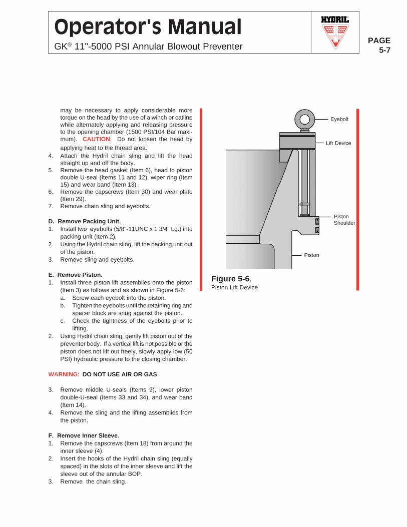
E. Remove Piston.1. Install three piston lift assemblies onto the piston
(Item 3) as follows and as shown in Figure 5-6:a. Screw each eyebolt into the piston.b. Tighten the eyebolts until the retaining ring and
spacer block are snug against the piston.c. Check the tightness of the eyebolts prior to
lifting.2. Using Hydril chain sling, gently lift piston out of the
preventer body. If a vertical lift is not possible or thepiston does not lift out freely, slowly apply low (50PSI) hydraulic pressure to the closing chamber.
WARNING: DO NOT USE AIR OR GAS.
3. Remove middle U-seals (Items 9), lower pistondouble-U-seal (Items 33 and 34), and wear band(Item 14).
4. Remove the sling and the lifting assemblies fromthe piston.
F. Remove Inner Sleeve.1. Remove the capscrews (Item 18) from around the
inner sleeve (4).2. Insert the hooks of the Hydril chain sling (equally
spaced) in the slots of the inner sleeve and lift thesleeve out of the annular BOP.
3. Remove the chain sling.
Eyebolt
Lift Device
PistonShoulder
Piston
Figure 5-6.Piston Lift Device
R
PAGE5-8
Operator's ManualGK® 11"-5000 PSI Annular Blowout Preventer
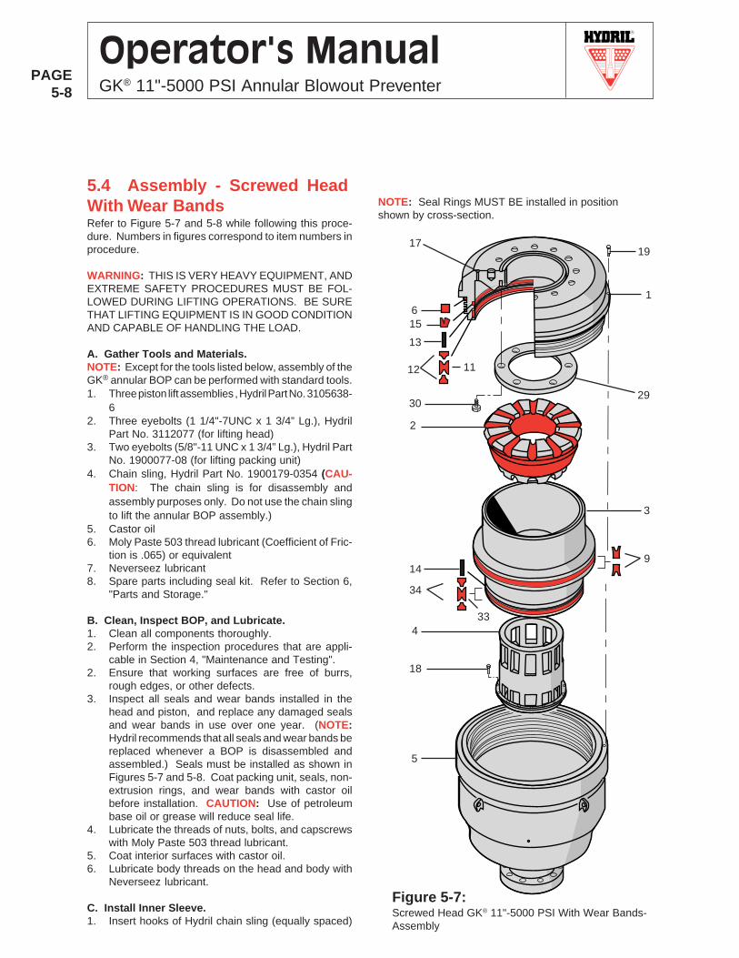
5.4 Assembly - Screwed HeadWith Wear Bands
1
3
9
1917
6
11
2930
2
34
4
18
5
NOTE: Seal Rings MUST BE installed in positionshown by cross-section.
Refer to Figure 5-7 and 5-8 while following this proce-dure. Numbers in figures correspond to item numbers inprocedure.
WARNING: THIS IS VERY HEAVY EQUIPMENT, ANDEXTREME SAFETY PROCEDURES MUST BE FOL-LOWED DURING LIFTING OPERATIONS. BE SURETHAT LIFTING EQUIPMENT IS IN GOOD CONDITIONAND CAPABLE OF HANDLING THE LOAD.
A. Gather Tools and Materials.NOTE: Except for the tools listed below, assembly of theGK® annular BOP can be performed with standard tools.1. Three piston lift assemblies , Hydril Part No. 3105638-
62. Three eyebolts (1 1/4"-7UNC x 1 3/4” Lg.), Hydril
Part No. 3112077 (for lifting head)3. Two eyebolts (5/8"-11 UNC x 1 3/4” Lg.), Hydril Part
No. 1900077-08 (for lifting packing unit)4. Chain sling, Hydril Part No. 1900179-0354 (CAU-
TION: The chain sling is for disassembly andassembly purposes only. Do not use the chain slingto lift the annular BOP assembly.)
5. Castor oil6. Moly Paste 503 thread lubricant (Coefficient of Fric-
tion is .065) or equivalent7. Neverseez lubricant8. Spare parts including seal kit. Refer to Section 6,
"Parts and Storage."
B. Clean, Inspect BOP, and Lubricate.1. Clean all components thoroughly.2. Perform the inspection procedures that are appli-
cable in Section 4, "Maintenance and Testing".2. Ensure that working surfaces are free of burrs,
rough edges, or other defects.3. Inspect all seals and wear bands installed in the
head and piston, and replace any damaged sealsand wear bands in use over one year. (NOTE:Hydril recommends that all seals and wear bands bereplaced whenever a BOP is disassembled andassembled.) Seals must be installed as shown inFigures 5-7 and 5-8. Coat packing unit, seals, non-extrusion rings, and wear bands with castor oilbefore installation. CAUTION: Use of petroleumbase oil or grease will reduce seal life.
4. Lubricate the threads of nuts, bolts, and capscrewswith Moly Paste 503 thread lubricant.
5. Coat interior surfaces with castor oil.6. Lubricate body threads on the head and body with
Neverseez lubricant.
C. Install Inner Sleeve.1. Insert hooks of Hydril chain sling (equally spaced)
Figure 5-7:Screwed Head GK® 11"-5000 PSI With Wear Bands-Assembly
15
13
12
33
14
R
PAGE5-9
Operator's ManualGK® 11"-5000 PSI Annular Blowout Preventer
into slots in inner sleeve (Item 4) and install thesleeve into the bore of the body.
2. Install the capscrews (Item 18) and torque to 150 lb-ft (203 N•m).
3. Remove chain sling.
D. Install Piston.1. Install the lower piston double U-seal (Items 33 and
34), and the wear band (Item 14) on the lowersegment of the piston (Item 3).
2. Install the middle U-seals (Item 9) on the uppersegment of the piston.
3. Install the piston lift assemblies onto the piston asshown in Figure 5-6. Attach the Hydril chain sling tothe eyebolts and install the piston over the innersleeve (Item 4) and into the body. Ensure that thepiston is aligned vertically with the body prior tolowering. Vent Close port. With proper verticalalignment, the piston will slide its normal full stroketo the bottom of the preventer body. CAUTION: Becareful not to damage the seals during assembly.
4. Remove the chain sling and piston lift assembliesfrom the piston.
E. Install Packing Unit.1. Lubricate the bowl of the piston (Item 3) and pack-
ing unit (Item 2) with castor oil. Install two eyebolts(5/8"-11 UNC x 1 3/4” Lg.) into packing unit. UsingHydril chain sling, lift the packing unit and set it intothe bowl of the piston.
2. Remove the chain sling and eyebolts from thepacking unit.
F. Install Head.1. Install the wear plate (Item 29) and capscrews (Item
30) on the inner face of the annular head (Item 1).Torque the capscrews to 50 lb-ft (68 N•m).
2. Install the head gasket (Item 6) in the seal grooveon the outside diameter of the head, just below themajor diameter and above the body threads.
3. Install the head to piston seal, consisting of adouble U-seal (Item 11) and two non-extrusionrings (Item 12), the wear band (Item 13), and thewiper ring (Item 15) into the grooves on the insidebottom diameter.
4. Install three eyebolts (1 1/4"-7UNC x 1 3/4” Lg.) intothe head.
5. Lubricate the body threads on the outside diameterof the head and the inside diameter of the body(Item 5) with Neverseez lubricant.
6. Install the head into the body so that the screwthreads on the head engage the threads of thebody. Remove the chain sling.
7. Tighten the head clockwise (right hand) as shownin Figure 5-2, using the pipe or rod from Step C of
the disassembly procedure, until the shoulder on thehead engages the body. A vertical lift, using the chainsling attached to the eyebolts, will reduce the weight onthe threads and reduce the required turning torque.Align the head lock bracket with the hole in the body.Lubricate the lock screw threads (Item 19) with MolyPaste 503 and install. Tighten the lock screw using 60lb-ft (80 N•m) torque.
8. Remove the chain sling and eyebolts from the head.9. Perform seal and packing unit test procedures in Sec-
tion 4, "Maintenance and Testing."
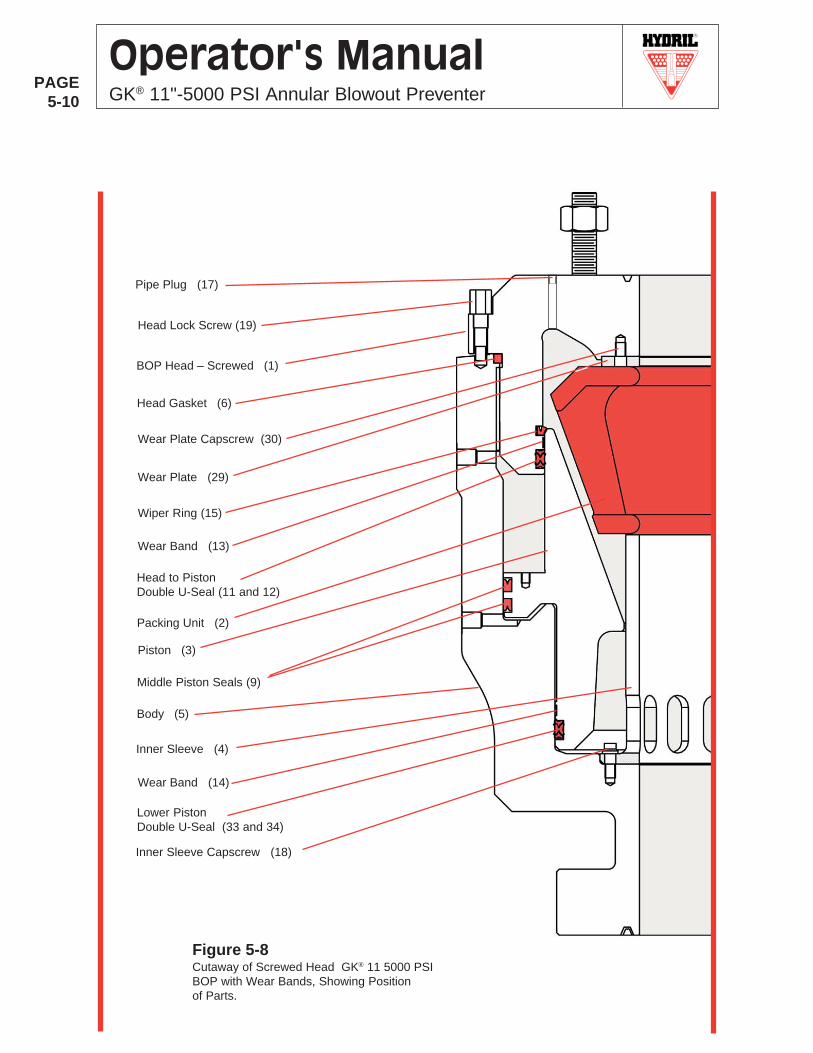
R
PAGE5-10
Operator's ManualGK® 11"-5000 PSI Annular Blowout Preventer
Figure 5-8Cutaway of Screwed Head GK® 11 5000 PSIBOP with Wear Bands, Showing Positionof Parts.
Pipe Plug (17)
BOP Head – Screwed (1)
Wear Plate Capscrew (30)
Head Gasket (6)
Wear Plate (29)
Wiper Ring (15)
Packing Unit (2)
Piston (3)
Middle Piston Seals (9)
Body (5)
Inner Sleeve (4)
Lower PistonDouble U-Seal (33 and 34)
Inner Sleeve Capscrew (18)
Head Lock Screw (19)
Head to PistonDouble U-Seal (11 and 12)
Wear Band (14)
Wear Band (13)
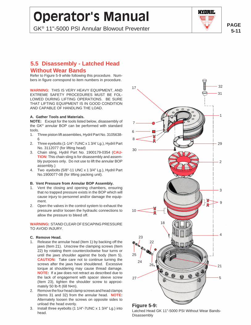
R
PAGE5-11
Operator's ManualGK® 11"-5000 PSI Annular Blowout Preventer
Figure 5-9:Latched Head GK 11"-5000 PSI Without Wear Bands-Disassembly
31
3
1
9
7
829
30
2
10
4
18
5
26
25
24
23
21
27
22
17 32
5.5 Disassembly - Latched HeadWithout Wear BandsRefer to Figure 5-9 while following this procedure. Num-bers in figure correspond to item numbers in procedure.
WARNING: THIS IS VERY HEAVY EQUIPMENT, ANDEXTREME SAFETY PROCEDURES MUST BE FOL-LOWED DURING LIFTING OPERATIONS. BE SURETHAT LIFTING EQUIPMENT IS IN GOOD CONDITIONAND CAPABLE OF HANDLING THE LOAD.
A. Gather Tools and Materials.NOTE: Except for the tools listed below, disassembly ofthe GK® annular BOP can be performed with standardtools.1. Three piston lift assemblies, Hydril Part No. 3105638-
62. Three eyebolts (1-1/4"-7UNC x 1 3/4’ Lg.), Hydril Part
No. 3112077 (for lifting head)3. Chain sling, Hydril Part No. 1900179-0354 (CAU-
TION: This chain sling is for disassembly and assem-bly purposes only. Do not use to lift the annular BOPassembly.)
4. Two eyebolts (5/8"-11 UNC x 1 3/4” Lg.), Hydril PartNo.1900077-08 (for lifting packing unit).
B. Vent Pressure from Annular BOP Assembly.1. Vent the closing and opening chambers, ensuring
that no trapped pressure exists in the BOP which willcause injury to personnel and/or damage the equip-ment.
2. Open the valves in the control system to exhaust thepressure and/or loosen the hydraulic connections toallow the pressure to bleed off.
WARNING: STAND CLEAR OF ESCAPING PRESSURETO AVOID INJURY.
C. Remove Head.1. Release the annular head (Item 1) by backing off the
jaws (Item 21). Unscrew the clamping screws (Item22) by rotating them counterclockwise four turns oruntil the jaws shoulder against the body (Item 5).CAUTION: Take care not to continue turning thescrews after the jaws have shouldered. Excessivetorque at shouldering may cause thread damage.NOTE: If a jaw does not retract as described due tothe lack of engagement with spacer sleeve screw(Item 23), tighten the shoulder screw to approxi-mately 50 lb-ft (68 N•m).
2. Remove the four head clamp screws and head clamps(Items 31 and 32) from the annular head. NOTE:Alternately loosen the screws on opposite sides tounload the head evenly.
3. Install three eyebolts (1 1/4"-7UNC x 1 3/4” Lg.) intohead.
6
R
PAGE5-12
Operator's ManualGK® 11"-5000 PSI Annular Blowout Preventer
4. Using Hydril chain sling , lift the head out of the body.Remove sling and eyebolts.
5. Remove the six cap screws (Item 30) and the wearplate (Item 29).
6. Remove the head dirt seal (Item 7), Head gasket(Item 6), and upper U-seals (Items 8).
D. Remove Packing Unit.1. Install two eyebolts (5/8"-11UNC x 1 3/4” Lg.) into
packing unit (Item 2).2. Using Hydril chain sling, lift the packing unit out of the
piston (Item 3).3. Remove sling and eyebolts.
E. Remove Piston.1. Install three piston lifting devices onto the piston
(Item 3) as follows and as shown in Figure 5-6:a. Position each lift device over the top edge of the
piston above the eyebolt holes in the pistonshoulder, taking care not to damage the sealingsurface on the outside diameter.
b. Tighten the eyebolts until the lift devices aresnug against the piston shoulder.
c. Check the tightness of the eyebolts prior tolifting.
2. Using Hydril chain sling 1900179-0354, gently liftpiston out of the preventer body. If a vertical lift is notpossible or the piston does not lift out freely, slowlyapply low (50 PSI) hydraulic pressure to the closingchamber.
WARNING: DO NOT USE AIR OR GAS.
3. Remove the lift devices from the piston, taking carenot to damage the sealing surface on the outsidediameter.
4. Remove the middle U-seals (Items 9) and the lowerU-seals (Items 10).
F. Remove Inner Sleeve.1. Remove the capscrews (Item 18) from around the
inner sleeve (Item 4).2. Using Hydril chain sling 1900178-0354, attach the
hooks (equally spaced) into the slots in the sleeveand lift the inner sleeve out of the annular BOP.
3. Remove sling.
G. Remove Jaws.Perform the following procedure for each jaw (Item 19).1. Remove pipe plug (Item 25).2. Hold clamping screw (Item 22) and remove spacer
sleeve screw (Item 23) from the clamping screw.3. Remove the clamping screw and spacer sleeve (Item
24) from the body (Item 5). Remove spacer sleevefrom the clamping screw. Remove the jaw (21) fromthe inside of the body. NOTE: Keep the jaws insequence so that they can be returned to their originalposition.
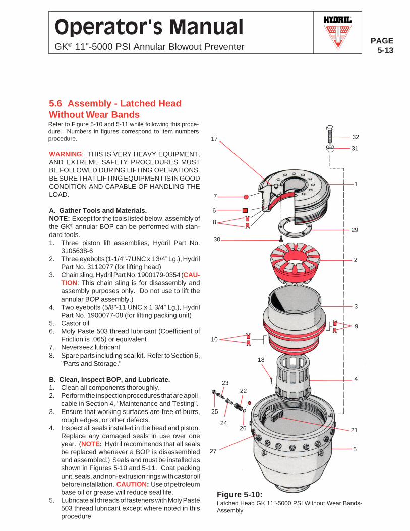
R
PAGE5-13
Operator's ManualGK® 11"-5000 PSI Annular Blowout Preventer
WARNING: THIS IS VERY HEAVY EQUIPMENT,AND EXTREME SAFETY PROCEDURES MUSTBE FOLLOWED DURING LIFTING OPERATIONS.BE SURE THAT LIFTING EQUIPMENT IS IN GOODCONDITION AND CAPABLE OF HANDLING THELOAD.
A. Gather Tools and Materials.NOTE: Except for the tools listed below, assembly ofthe GK® annular BOP can be performed with stan-dard tools.1. Three piston lift assemblies, Hydril Part No.
3105638-62. Three eyebolts (1-1/4"-7UNC x 1 3/4” Lg.), Hydril
Part No. 3112077 (for lifting head)3. Chain sling, Hydril Part No. 1900179-0354 (CAU-
TION: This chain sling is for disassembly andassembly purposes only. Do not use to lift theannular BOP assembly.)
4. Two eyebolts (5/8"-11 UNC x 1 3/4” Lg.), HydrilPart No. 1900077-08 (for lifting packing unit)
5. Castor oil6. Moly Paste 503 thread lubricant (Coefficient of
Friction is .065) or equivalent7. Neverseez lubricant8. Spare parts including seal kit. Refer to Section 6,
"Parts and Storage."
B. Clean, Inspect BOP, and Lubricate.1. Clean all components thoroughly.2. Perform the inspection procedures that are appli-
cable in Section 4, "Maintenance and Testing".3. Ensure that working surfaces are free of burrs,
rough edges, or other defects.4. Inspect all seals installed in the head and piston.
Replace any damaged seals in use over oneyear. (NOTE: Hydril recommends that all sealsbe replaced whenever a BOP is disassembledand assembled.) Seals and must be installed asshown in Figures 5-10 and 5-11. Coat packingunit, seals, and non-extrusion rings with castor oilbefore installation. CAUTION: Use of petroleumbase oil or grease will reduce seal life.
5. Lubricate all threads of fasteners with Moly Paste503 thread lubricant except where noted in thisprocedure.
5.6 Assembly - Latched HeadWithout Wear BandsRefer to Figure 5-10 and 5-11 while following this proce-dure. Numbers in figures correspond to item numbersprocedure.
Figure 5-10:Latched Head GK 11"-5000 PSI Without Wear Bands-Assembly
3
1
9
7
829
30
2
10
4
18
5
6
26
25
24
23
21
27
22
17
31
32
R
PAGE5-14
Operator's ManualGK® 11"-5000 PSI Annular Blowout Preventer
6. Coat interior surfaces with castor oil.
C. Install Jaws.1. Install the jaws (Item 21) into the annular body
with the short side of the teeth down and in thesame sequence as disassembled. NOTE: If anew jaw is installed within a set of well worn jaws,polish the new jaw to match existing jaws toensure equal load sharing.
2. Install the O-ring (Item 26) in the external grooveof each clamping screw (Item 22).
3. Install the clamping screws and screw them all-the-way in hand tight. CAUTION: Be careful notto overtighten the clamping screws, or the jaw willextend beyond the sides of the body.
4. Insert the spacer sleeve (Item 24) and spacersleeve screw (Item 23) through each clampingscrew. Turn the screws into the jaws (Item 21)until tight (approximately 50 lb-ft/68 N•m). IM-PORTANT: Do not lubricate the threads of thespacer sleeve screws.
5. Install pipe plugs (Item 25) into clamping screws.6. Ensure that all of the jaws are retracted fully by
turning the clamping screws counterclockwiseuntil the jaws are shouldered against the body.
D. Install Inner Sleeve.1. Using Hydril chain sling 1900179-0354, attach
the three hooks (evenly spaced) into the slots inthe sleeve and install the inner sleeve (Item 4)into the body.
2. Install the capscrews (Item 18) and torque to 150lb-ft (203 N•m).
3. Remove chain sling.
E. Install Piston.1. Install thelower U-seals (Item 10) on the lower
segment of the piston (Item 3).2. Install the middle U-seals (Item 9) onto the upper
segment of the piston. Orient the seal lips asshown in Figure 5-9 and/or 5-10.
3. Install the piston into the body using the piston liftdevices. Install each device onto the piston asshown in Figure 5-6, taking care not to damagethe sealing surface on the outside diameter.Lubricate all mating surfaces with castor oil be-fore lowering the piston over the inner sleeve.Ensure that the piston is aligned vertically withthe inner sleeve prior to lowering. Vent the Closeports to atmosphere. With proper vertical align-ment, the piston will slide its normal full stroke tothe bottom of the preventer body. CAUTION: Be
careful not to damage the sealing surfaces on theinside diameter of the body and the seals on theoutside diameter of the piston during assembly.
4. Remove the sling and lift devices from the piston,taking care not to damage the sealing surface onthe outside diameter.
F. Install Packing Unit.1. Lubricate the bowl of the piston (Item 3) and pack-
ing unit (Item 2) with castor oil. Install two eyebolts(5/8"-11UNC x 1 3/4” Lg.) into packing unit. UsingHydril chain sling 1900179-0354, lift the packingunit and set it into the bowl of the piston.
2. Remove the sling and eyebolts from the packingunit.
G. Install Head.1. Unscrew the clamping screws (Item 22) by rotating
them counterclockwise four turns or until the jawsshoulder against the body (Item 5). CAUTION:Take care not to continue turning the screws afterthe jaws have shouldered. Excessive torque atshouldering may cause thread damage. NOTE: Ifa jaw does not retract as described due to the lackof engagement with spacer sleeve screw (Item 23),tighten the spacer sleeve screw counterclockwise(left hand thread) to approximately 150 lb-ft (203N•m).
2. Install the wear plate (Item 29) on the inner face ofthe annular head (1) and install the capscrews(Item 30). Torque the capscrews to 50 lb-ft (68N•m).
3. Install the head dirt seal (Item 7), head gasket (6),and upper U-seals (Items 8) onto the head.
4. Install three eyebolts (1-1/4"-7UNC x 1 3/4” Lg.)into head.
5. Using Hydril chain sling 1900179-0354, lift andinstall the head into the annular body (Item 5).Remove the sling and eyebolts.
8. Install four head clamps (item 31) and screws (Item32) to secure the head fully into place. Tighten thehead clamp screws until tight.
9. Turn the clamping screws (Item 22) clockwise toengage the jaws (Item 21) fully into the locking ringsof the preventer head and apply 350 lb-ft (475 N•m)of torque. CAUTION: To prevent unequal clear-ance between the head and the body, tighten thejaws/latches alternately on opposite sides or in acrisscross pattern.
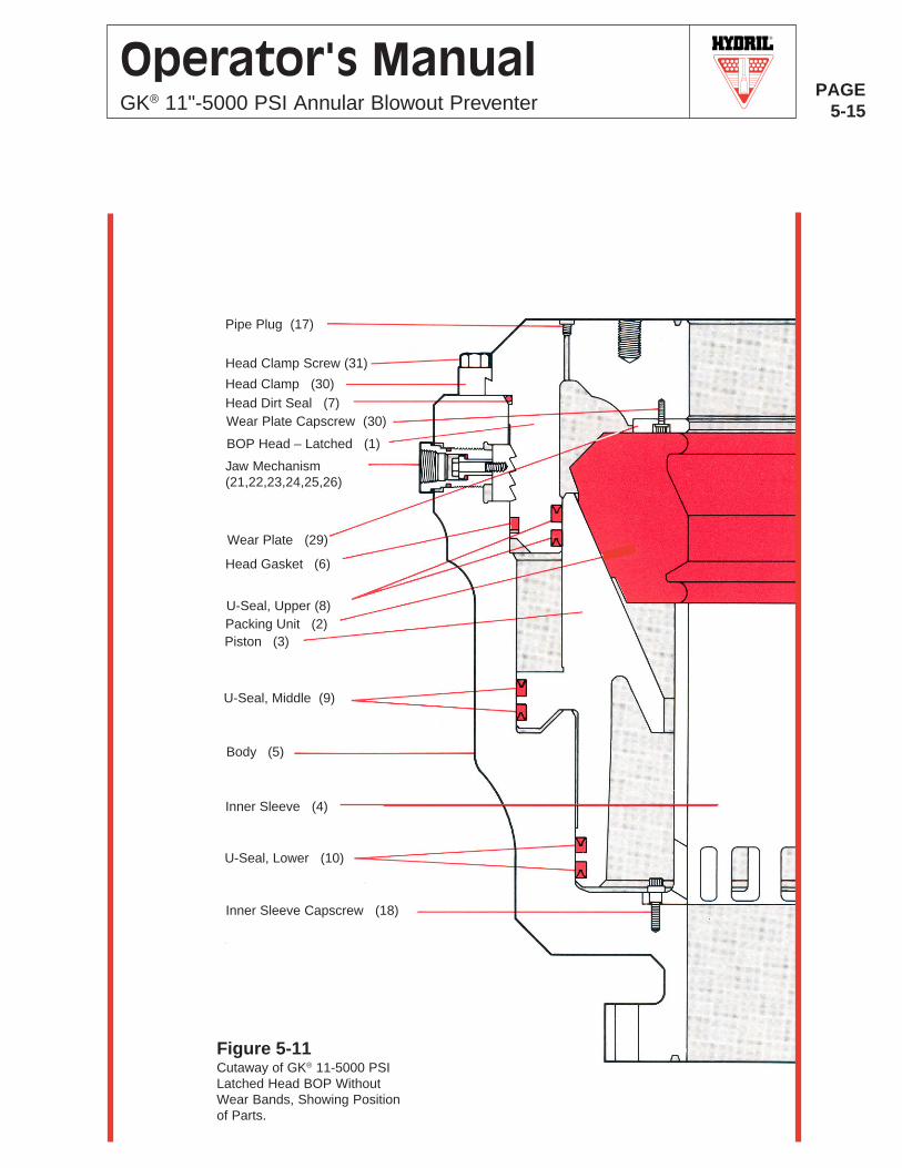
R
PAGE5-15
Operator's ManualGK® 11"-5000 PSI Annular Blowout Preventer
Figure 5-11Cutaway of GK® 11-5000 PSILatched Head BOP WithoutWear Bands, Showing Positionof Parts.
BOP Head – Latched (1)
Wear Plate Capscrew (30)
Head Gasket (6)
Packing Unit (2)Piston (3)
U-Seal, Middle (9)
Body (5)
Inner Sleeve (4)
U-Seal, Lower (10)
Inner Sleeve Capscrew (18)
U-Seal, Upper (8)
Pipe Plug (17)
Jaw Mechanism(21,22,23,24,25,26)
Wear Plate (29)
Head Clamp Screw (31)
Head Clamp (30)Head Dirt Seal (7)
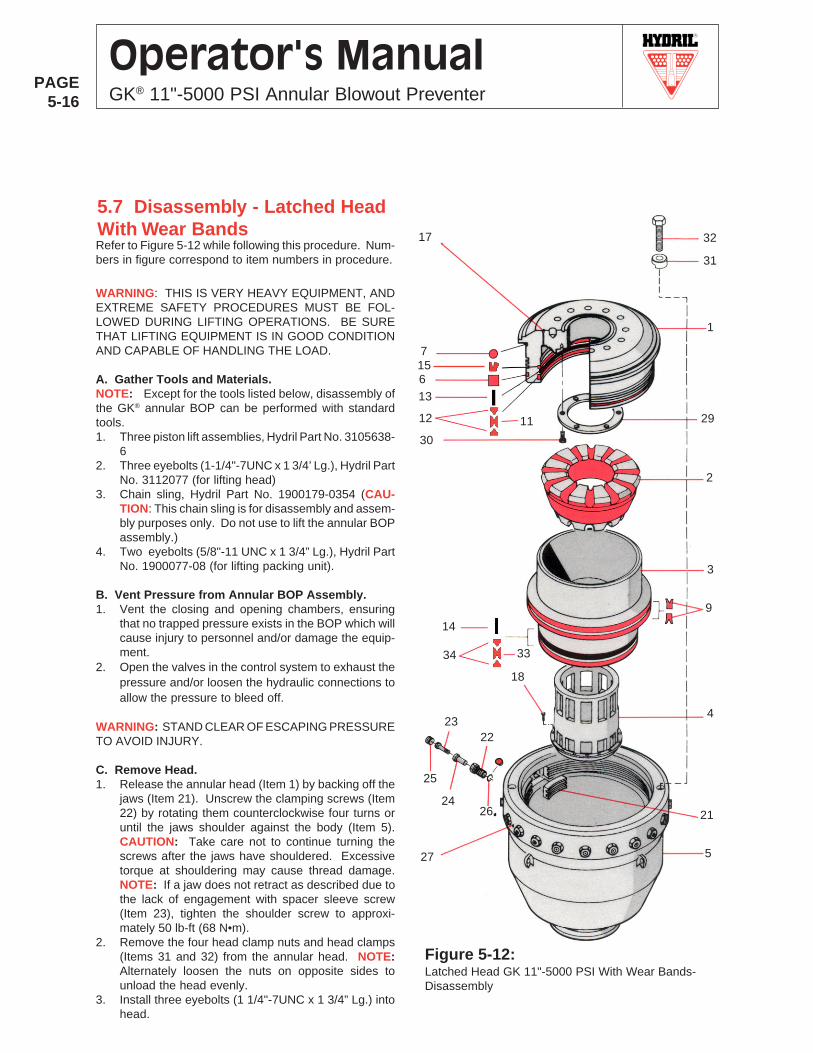
R
PAGE5-16
Operator's ManualGK® 11"-5000 PSI Annular Blowout Preventer
5.7 Disassembly - Latched HeadWith Wear BandsRefer to Figure 5-12 while following this procedure. Num-bers in figure correspond to item numbers in procedure.
WARNING: THIS IS VERY HEAVY EQUIPMENT, ANDEXTREME SAFETY PROCEDURES MUST BE FOL-LOWED DURING LIFTING OPERATIONS. BE SURETHAT LIFTING EQUIPMENT IS IN GOOD CONDITIONAND CAPABLE OF HANDLING THE LOAD.
A. Gather Tools and Materials.NOTE: Except for the tools listed below, disassembly ofthe GK® annular BOP can be performed with standardtools.1. Three piston lift assemblies, Hydril Part No. 3105638-
62. Three eyebolts (1-1/4"-7UNC x 1 3/4’ Lg.), Hydril Part
No. 3112077 (for lifting head)3. Chain sling, Hydril Part No. 1900179-0354 (CAU-
TION: This chain sling is for disassembly and assem-bly purposes only. Do not use to lift the annular BOPassembly.)
4. Two eyebolts (5/8"-11 UNC x 1 3/4” Lg.), Hydril PartNo. 1900077-08 (for lifting packing unit).
B. Vent Pressure from Annular BOP Assembly.1. Vent the closing and opening chambers, ensuring
that no trapped pressure exists in the BOP which willcause injury to personnel and/or damage the equip-ment.
2. Open the valves in the control system to exhaust thepressure and/or loosen the hydraulic connections toallow the pressure to bleed off.
WARNING: STAND CLEAR OF ESCAPING PRESSURETO AVOID INJURY.
C. Remove Head.1. Release the annular head (Item 1) by backing off the
jaws (Item 21). Unscrew the clamping screws (Item22) by rotating them counterclockwise four turns oruntil the jaws shoulder against the body (Item 5).CAUTION: Take care not to continue turning thescrews after the jaws have shouldered. Excessivetorque at shouldering may cause thread damage.NOTE: If a jaw does not retract as described due tothe lack of engagement with spacer sleeve screw(Item 23), tighten the shoulder screw to approxi-mately 50 lb-ft (68 N•m).
2. Remove the four head clamp nuts and head clamps(Items 31 and 32) from the annular head. NOTE:Alternately loosen the nuts on opposite sides tounload the head evenly.
3. Install three eyebolts (1 1/4"-7UNC x 1 3/4” Lg.) intohead.
Figure 5-12:Latched Head GK 11"-5000 PSI With Wear Bands-Disassembly
31
3
1
12
7
11 29
30
2
9
4
18
5
6
26
25
24
23
21
27
22
17 32
13
3334
14
15
R
PAGE5-17
Operator's ManualGK® 11"-5000 PSI Annular Blowout Preventer
4. Using Hydril chain sling , lift the head out of the body.Remove sling and eyebolts.
5. Remove the head dirt seal (Item 7), wiper ring (Item15), head gasket (Item 6), head to piston double U-seal (Items 11 and 12), and the wear band (Item 13)from the head.
6. Remove the six cap screws (Item 30) and the wearplate (Item 29).
D. Remove Packing Unit.1. Install two eyebolts (5/8"-11UNC x 1 3/4” Lg.) into
packing unit (Item 2).2. Using Hydril chain sling, lift the packing unit out of the
piston (Item 3).3. Remove sling and eyebolts.
E. Remove Piston.1. Install three piston lifting devices onto the piston (Item
3) as follows and as shown in Figure 5-6:a. Position each lift device over the top edge of the
piston above the eyebolt holes in the pistonshoulder, taking care not to damage the sealingsurface on the outside diameter.
b. Tighten the eyebolts until the lift devices aresnug against the piston shoulder.
c. Check the tightness of the eyebolts prior tolifting.
2. Using Hydril chain sling 1900179-0354, gently liftpiston out of the preventer body. If a vertical lift is notpossible or the piston does not lift out freely, slowlyapply low (50 PSI) hydraulic pressure to the closingchamber.
WARNING: DO NOT USE AIR OR GAS.
3. Remove the middle U-seals (Item 9), lower pistondouble U-seal (Items 33 and 34), and the wear band(Item 14) from the piston.
4. Remove the lift devices from the piston, taking carenot to damage the sealing surface on the outsidediameter.
F. Remove Inner Sleeve.1. Remove the capscrews (Item 18) from around the
inner sleeve (Item 4).2. Using Hydril chain sling 1900178-0354, attach the
hooks (equally spaced) into the slots in the sleeveand lift the inner sleeve out of the annular BOP.
3. Remove sling.
G. Remove Radial Latches.Perform the following procedure for each radial latch (Item19).1. Remove pipe plug (Item 25).2. Hold clamping screw (Item 22) and remove spacer
sleeve screw (Item 23) from the clamping screw.3. Remove the O-ring (Item 26) from the clamping screw.4. Remove the clamping screw and spacer sleeve (Item
24) from the body (Item 5). Remove spacer sleeve fromthe clamping screw. Remove the jaws (Item 21) fromthe inside of the body. NOTE: Keep the jaws insequence so that they can be returned to their originalposition.
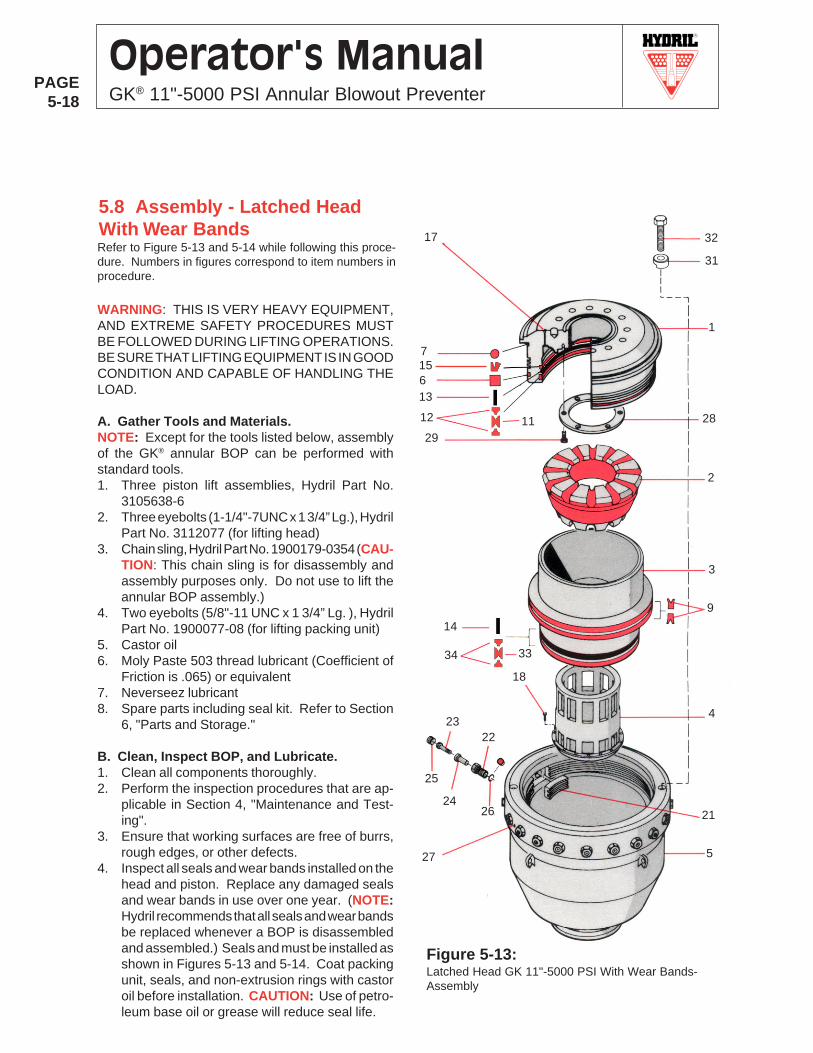
R
PAGE5-18
Operator's ManualGK® 11"-5000 PSI Annular Blowout Preventer
5.8 Assembly - Latched HeadWith Wear BandsRefer to Figure 5-13 and 5-14 while following this proce-dure. Numbers in figures correspond to item numbers inprocedure.
WARNING: THIS IS VERY HEAVY EQUIPMENT,AND EXTREME SAFETY PROCEDURES MUSTBE FOLLOWED DURING LIFTING OPERATIONS.BE SURE THAT LIFTING EQUIPMENT IS IN GOODCONDITION AND CAPABLE OF HANDLING THELOAD.
A. Gather Tools and Materials.NOTE: Except for the tools listed below, assemblyof the GK® annular BOP can be performed withstandard tools.1. Three piston lift assemblies, Hydril Part No.
3105638-62. Three eyebolts (1-1/4"-7UNC x 1 3/4” Lg.), Hydril
Part No. 3112077 (for lifting head)3. Chain sling, Hydril Part No. 1900179-0354 (CAU-
TION: This chain sling is for disassembly andassembly purposes only. Do not use to lift theannular BOP assembly.)
4. Two eyebolts (5/8"-11 UNC x 1 3/4” Lg. ), HydrilPart No. 1900077-08 (for lifting packing unit)
5. Castor oil6. Moly Paste 503 thread lubricant (Coefficient of
Friction is .065) or equivalent7. Neverseez lubricant8. Spare parts including seal kit. Refer to Section
6, "Parts and Storage."
B. Clean, Inspect BOP, and Lubricate.1. Clean all components thoroughly.2. Perform the inspection procedures that are ap-
plicable in Section 4, "Maintenance and Test-ing".
3. Ensure that working surfaces are free of burrs,rough edges, or other defects.
4. Inspect all seals and wear bands installed on thehead and piston. Replace any damaged sealsand wear bands in use over one year. (NOTE:Hydril recommends that all seals and wear bandsbe replaced whenever a BOP is disassembledand assembled.) Seals and must be installed asshown in Figures 5-13 and 5-14. Coat packingunit, seals, and non-extrusion rings with castoroil before installation. CAUTION: Use of petro-leum base oil or grease will reduce seal life.
Figure 5-13:Latched Head GK 11"-5000 PSI With Wear Bands-Assembly
31
3
1
12
7
11 28
29
2
9
4
18
5
6
26
25
24
23
21
27
22
17 32
13
3334
14
15
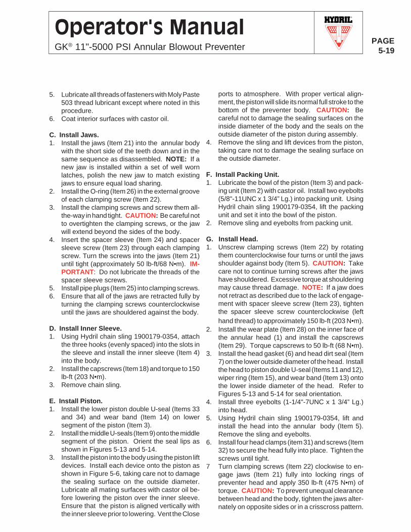
R
PAGE5-19
Operator's ManualGK® 11"-5000 PSI Annular Blowout Preventer
5. Lubricate all threads of fasteners with Moly Paste503 thread lubricant except where noted in thisprocedure.
6. Coat interior surfaces with castor oil.
C. Install Jaws.1. Install the jaws (Item 21) into the annular body
with the short side of the teeth down and in thesame sequence as disassembled. NOTE: If anew jaw is installed within a set of well wornlatches, polish the new jaw to match existingjaws to ensure equal load sharing.
2. Install the O-ring (Item 26) in the external grooveof each clamping screw (Item 22).
3. Install the clamping screws and screw them all-the-way in hand tight. CAUTION: Be careful notto overtighten the clamping screws, or the jawwill extend beyond the sides of the body.
4. Insert the spacer sleeve (Item 24) and spacersleeve screw (Item 23) through each clampingscrew. Turn the screws into the jaws (Item 21)until tight (approximately 50 lb-ft/68 N•m). IM-PORTANT: Do not lubricate the threads of thespacer sleeve screws.
5. Install pipe plugs (Item 25) into clamping screws.6. Ensure that all of the jaws are retracted fully by
turning the clamping screws counterclockwiseuntil the jaws are shouldered against the body.
D. Install Inner Sleeve.1. Using Hydril chain sling 1900179-0354, attach
the three hooks (evenly spaced) into the slots inthe sleeve and install the inner sleeve (Item 4)into the body.
2. Install the capscrews (Item 18) and torque to 150lb-ft (203 N•m).
3. Remove chain sling.
E. Install Piston.1. Install the lower piston double U-seal (Items 33
and 34) and wear band (Item 14) on lowersegment of the piston (Item 3).
2. Install the middle U-seals (Item 9) onto the middlesegment of the piston. Orient the seal lips asshown in Figures 5-13 and 5-14.
3. Install the piston into the body using the piston liftdevices. Install each device onto the piston asshown in Figure 5-6, taking care not to damagethe sealing surface on the outside diameter.Lubricate all mating surfaces with castor oil be-fore lowering the piston over the inner sleeve.Ensure that the piston is aligned vertically withthe inner sleeve prior to lowering. Vent the Close
ports to atmosphere. With proper vertical align-ment, the piston will slide its normal full stroke to thebottom of the preventer body. CAUTION: Becareful not to damage the sealing surfaces on theinside diameter of the body and the seals on theoutside diameter of the piston during assembly.
4. Remove the sling and lift devices from the piston,taking care not to damage the sealing surface onthe outside diameter.
F. Install Packing Unit.1. Lubricate the bowl of the piston (Item 3) and pack-
ing unit (Item 2) with castor oil. Install two eyebolts(5/8"-11UNC x 1 3/4” Lg.) into packing unit. UsingHydril chain sling 1900179-0354, lift the packingunit and set it into the bowl of the piston.
2. Remove sling and eyebolts from packing unit.
G. Install Head.1. Unscrew clamping screws (Item 22) by rotating
them counterclockwise four turns or until the jawsshoulder against body (Item 5). CAUTION: Takecare not to continue turning screws after the jawshave shouldered. Excessive torque at shoulderingmay cause thread damage. NOTE: If a jaw doesnot retract as described due to the lack of engage-ment with spacer sleeve screw (Item 23), tightenthe spacer sleeve screw counterclockwise (lefthand thread) to approximately 150 lb-ft (203 N•m).
2. Install the wear plate (Item 28) on the inner face ofthe annular head (1) and install the capscrews(Item 29). Torque capscrews to 50 lb-ft (68 N•m).
3. Install the head gasket (6) and head dirt seal (Item7) on the lower outside diameter of the head. Installthe head to piston double U-seal (Items 11 and 12),wiper ring (Item 15), and wear band (Item 13) ontothe lower inside diameter of the head. Refer toFigures 5-13 and 5-14 for seal orientation.
4. Install three eyebolts (1-1/4"-7UNC x 1 3/4” Lg.)into head.
5. Using Hydril chain sling 1900179-0354, lift andinstall the head into the annular body (Item 5).Remove the sling and eyebolts.
6. Install four head clamps (item 31) and screws (Item32) to secure the head fully into place. Tighten thescrews until tight.
7 Turn clamping screws (Item 22) clockwise to en-gage jaws (Item 21) fully into locking rings ofpreventer head and apply 350 lb-ft (475 N•m) oftorque. CAUTION: To prevent unequal clearancebetween head and the body, tighten the jaws alter-nately on opposite sides or in a crisscross pattern.
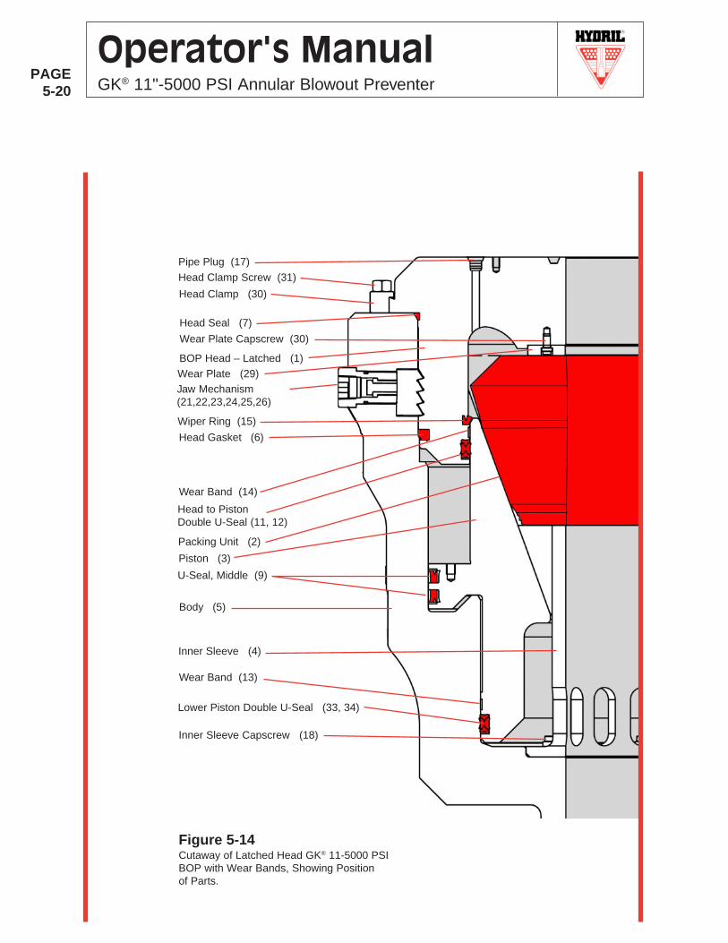
R
PAGE5-20
Operator's ManualGK® 11"-5000 PSI Annular Blowout Preventer
Figure 5-14Cutaway of Latched Head GK® 11-5000 PSIBOP with Wear Bands, Showing Positionof Parts.
Head Clamp (30)
BOP Head – Latched (1)
Wear Plate Capscrew (30)
Head Gasket (6)
Packing Unit (2)
Piston (3)
U-Seal, Middle (9)
Body (5)
Inner Sleeve (4)
Lower Piston Double U-Seal (33, 34)
Inner Sleeve Capscrew (18)
Wiper Ring (15)
Head Clamp Screw (31)
Head Seal (7)
Pipe Plug (17)
Jaw Mechanism(21,22,23,24,25,26)
Wear Plate (29)
Head to PistonDouble U-Seal (11, 12)
Wear Band (13)
Wear Band (14)
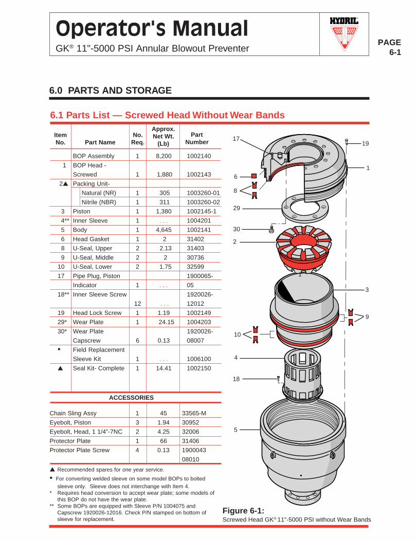
R
PAGE6-1
Operator's ManualGK® 11"-5000 PSI Annular Blowout Preventer
6.1 Parts List — Screwed Head Without Wear BandsApprox.Net Wt.
(Lb)Part
NumberNo.
Req.Part NameItemNo.
1
3
1
9
1917
6
8
29
30
2
10
4
18
5
ACCESSORIES
▲ Recommended spares for one year service.
• For converting welded sleeve on some model BOPs to boltedsleeve only. Sleeve does not interchange with Item 4.
* Requires head conversion to accept wear plate; some models ofthis BOP do not have the wear plate.
** Some BOPs are equipped with Sleeve P/N 1004075 andCapscrew 1920026-12016. Check P/N stamped on bottom ofsleeve for replacement.
Figure 6-1:Screwed Head GK® 11"-5000 PSI without Wear Bands
Chain Sling Assy 1 45 33565-M
Eyebolt, Piston 3 1.94 30952
Eyebolt, Head, 1 1/4”-7NC 2 4.25 32006
Protector Plate 1 66 31406
Protector Plate Screw 4 0.13 1900043
08010
6.0 PARTS AND STORAGE
BOP Assembly 1 8,200 1002140
1 BOP Head -
Screwed 1 1,880 1002143
2▲ Packing Unit-
Natural (NR) 1 305 1003260-01
Nitrile (NBR) 1 311 1003260-02
3 Piston 1 1,380 1002145-1
4** Inner Sleeve 1 . . . 1004201
5 Body 1 4,645 1002141
6 Head Gasket 1 2 31402
8 U-Seal, Upper 2 2.13 31403
9 U-Seal, Middle 2 2 30736
10 U-Seal, Lower 2 1.75 32599
17 Pipe Plug, Piston 1900065-
Indicator 1 . . . 05
18** Inner Sleeve Screw 1920026-
12 . . . 12012
19 Head Lock Screw 1 1.19 1002149
29* Wear Plate 1 24.15 1004203
30* Wear Plate 1920026-
Capscrew 6 0.13 08007
• Field Replacement
Sleeve Kit 1 . . . 1006100
▲ Seal Kit- Complete 1 14.41 1002150
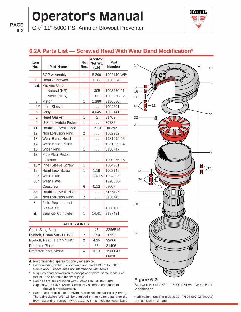
R
PAGE6-2
Operator's ManualGK® 11"-5000 PSI Annular Blowout Preventer
6.2A Parts List — Screwed Head With Wear Band Modificationa
Approx.Net Wt.
(Lb)Part
NumberNo.Req.Part Name
ItemNo.
ACCESSORIES
▲ Recommended spares for one year service.• For converting welded sleeve on some model BOPs to bolted
sleeve only. Sleeve does not interchange with Item 4.* Requires head conversion to accept wear plate; some models of
this BOP do not have the wear plate.** Some BOPs are equipped with Sleeve P/N 1004075 and
Capscrew 1920026-12016. Check P/N stamped on bottom ofsleeve for replacement.
a Wear band modification at Hydril Authorized Repair Facility (ARF).The abbreviation “WB” will be stamped on the name plate after theBOP assembly number (XXXXXXX-WB) to indicate wear band
1
3
1917
6
12
2930
2
334
18
5
11
9
13
14
15
Figure 6-2:Screwed Head GK® 11"-5000 PSI with Wear BandModification
34
Chain Sling Assy 1 45 33565-M
Eyebolt, Piston 5/8”-11UNC 2 1.94 30952
Eyebolt, Head, 1 1/4”-7UNC 2 4.25 32006
Protector Plate 1 66 31406
Protector Plate Screw 4 0.13 1900043
08010
modification. See Parts List 6.2B (PNI04-007-02 Rev A1)for modification kit parts.
BOP Assembly 1 8,200 1002140-WBa
1 Head - Screwed 1 1,880 3136824
2▲ Packing Unit-
Natural (NR) 1 305 1003260-01
Nitrile (NBR) 1 311 1003260-02
3 Piston 1 1,380 3136680
4** Inner Sleeve 1 . . . 1004201
5 Body 1 4,645 1002141
6 Head Gasket 1 2 31402
9 U-Seal, Middle Piston 1 . . . 30736
11 Double U-Seal, Head 1 2.13 1002921
12 Non Extrusion Ring 2 . . . 1002922
13 Wear Band, Head 1 . . . 1931099-05
14 Wear Band, Piston 1 . . . 1931099-04
15 Wiper Ring 1 . . . 3136747
17 Pipe Plug, Piston
Indicator 1 . . . 1900065-05
18** Inner Sleeve Screw 1 1004201
19 Head Lock Screw 1 1.19 1002149
29* Wear Plate 1 24.15 1004203
30* Wear Plate 1920026-
Capscrew 6 0.13 08007
33 Double U-Seal, Piston 1 . . . 3136746
34 Non Extrusion Ring 2 . . . 3136745
• Field Replacement
Sleeve Kit 1 . . . 1006100
▲ Seal Kit- Complete 1 14.41 3137431
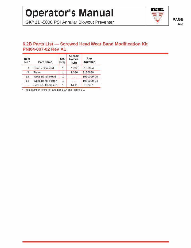
R
PAGE6-3
Operator's ManualGK® 11"-5000 PSI Annular Blowout Preventer
6.2B Parts List — Screwed Head Wear Band Modification KitPNI04-007-02 Rev A1
Approx.Net Wt.
(Lb)Part
NumberNo.
Req.Part NameItemNo.a
a Item number refers to Parts List 6-2A and Figure 6-2.
1 Head - Screwed 1 1,880 3136824
3 Piston 1 1,380 3136680
13 Wear Band, Head 1 . . . 1931099-05
14 Wear Band, Piston 1 . . . 1931099-04
. . . Seal Kit- Complete 1 14.41 3137431
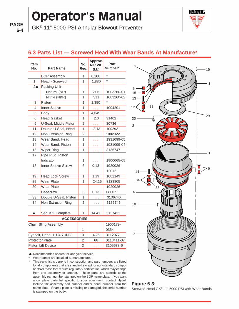
R
PAGE6-4
Operator's ManualGK® 11"-5000 PSI Annular Blowout Preventer
6.3 Parts List — Screwed Head With Wear Bands At Manufacturea
Approx.Net Wt.
(Lb)
PartNumber*
No.Req.Part Name
ItemNo.
ACCESSORIES
▲ Recommended spares for one year service.a Wear bands are installed at manufacture.* This parts list is generic in construction and part numbers are listed
for all components that are standard except for non-standard compo-nents or those that require regulatory certification, which may changefrom one assembly to another. These parts are specific to theassembly part number stamped on the BOP name plate. If you wanta complete parts list specific to your equipment, contact Hydril.Include the assembly part number and/or serial number from thename plate. If name plate is missing or damaged, the serial numberis stamped on the body.
1
3
9
1917
6
12
2930
2
4
18
5
11
33
Figure 6-3:Screwed Head GK® 11"-5000 PSI with Wear Bands
Chain Sling Assembly 1900179-
1 . . . 0354
Eyebolt, Head, 1 1/4-7UNC 3 4.25 3112077
Protector Plate 2 66 3113411-37
Piston Lift Device 3 . . . 3105638-6
34
15
13
14
BOP Assembly 1 8,200 *
1 Head - Screwed 1 1,880 *
2▲ Packing Unit-
Natural (NR) 1 305 1003260-01
Nitrile (NBR) 1 311 1003260-02
3 Piston 1 1,380 *
4 Inner Sleeve 1 . . . 1004201
5 Body 1 4,645 *
6 Head Gasket 1 2.0 31402
9 U-Seal, Middle Piston 2 . . . 30736
11 Double U-Seal, Head 1 2.13 1002921
12 Non Extrusion Ring 2 . . . 1002922
13 Wear Band, Head 1 . . . 1931099-05
14 Wear Band, Piston 1 . . . 1931099-04
15 Wiper Ring 1 . . . 3136747
17 Pipe Plug, Piston
Indicator 1 . . . 1900065-05
18 Inner Sleeve Screw 6 0.13 1920026-
12012
19 Head Lock Screw 1 1.19 1002149
29 Wear Plate 1 24.15 3123805
30 Wear Plate 1920026-
Capscrew 6 0.13 08007
33 Double U-Seal, Piston 1 . . . 3136746
34 Non Extrusion Ring 2 . . . 3136745
▲ Seal Kit- Complete 1 14.41 3137431
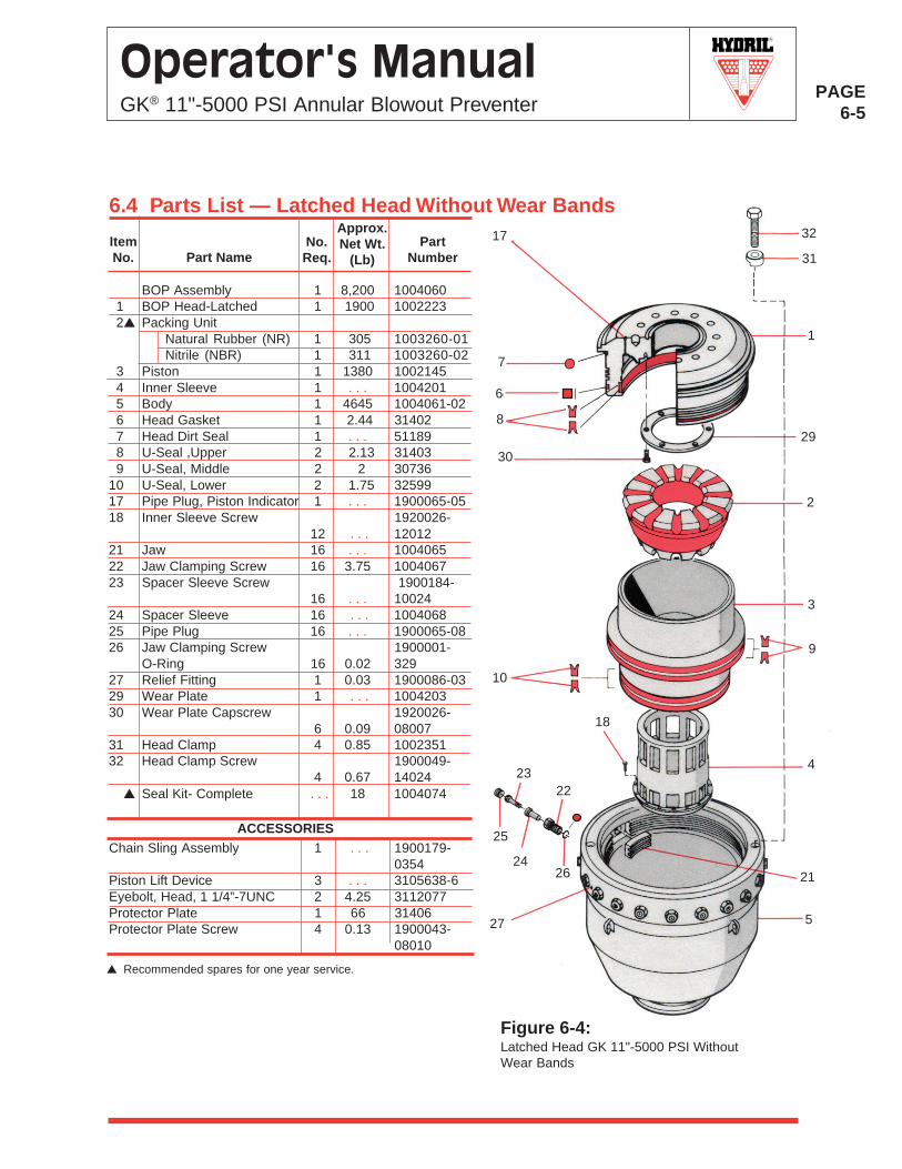
R
PAGE6-5
Operator's ManualGK® 11"-5000 PSI Annular Blowout Preventer
Approx.Net Wt.
(Lb)Part
NumberNo.Req.Part Name
ItemNo.
▲ Recommended spares for one year service.
ACCESSORIES
Figure 6-4:Latched Head GK 11"-5000 PSI WithoutWear Bands
3
1
9
7
829
30
2
10
4
18
5
6
26
25
24
23
21
27
22
17
6.4 Parts List — Latched Head Without Wear Bands
Chain Sling Assembly 1 . . . 1900179-0354
Piston Lift Device 3 . . . 3105638-6Eyebolt, Head, 1 1/4”-7UNC 2 4.25 3112077Protector Plate 1 66 31406Protector Plate Screw 4 0.13 1900043-
08010
31
32
BOP Assembly 1 8,200 1004060 1 BOP Head-Latched 1 1900 1002223 2▲ Packing Unit
Natural Rubber (NR) 1 305 1003260-01Nitrile (NBR) 1 311 1003260-02
3 Piston 1 1380 1002145 4 Inner Sleeve 1 . . . 1004201 5 Body 1 4645 1004061-02 6 Head Gasket 1 2.44 31402 7 Head Dirt Seal 1 . . . 51189 8 U-Seal ,Upper 2 2.13 31403 9 U-Seal, Middle 2 2 3073610 U-Seal, Lower 2 1.75 3259917 Pipe Plug, Piston Indicator 1 . . . 1900065-0518 Inner Sleeve Screw 1920026-
12 . . . 1201221 Jaw 16 . . . 100406522 Jaw Clamping Screw 16 3.75 100406723 Spacer Sleeve Screw 1900184-
16 . . . 1002424 Spacer Sleeve 16 . . . 100406825 Pipe Plug 16 . . . 1900065-0826 Jaw Clamping Screw 1900001-
O-Ring 16 0.02 32927 Relief Fitting 1 0.03 1900086-0329 Wear Plate 1 . . . 100420330 Wear Plate Capscrew 1920026-
6 0.09 0800731 Head Clamp 4 0.85 100235132 Head Clamp Screw 1900049-
4 0.67 14024 ▲ Seal Kit- Complete . . . 18 1004074
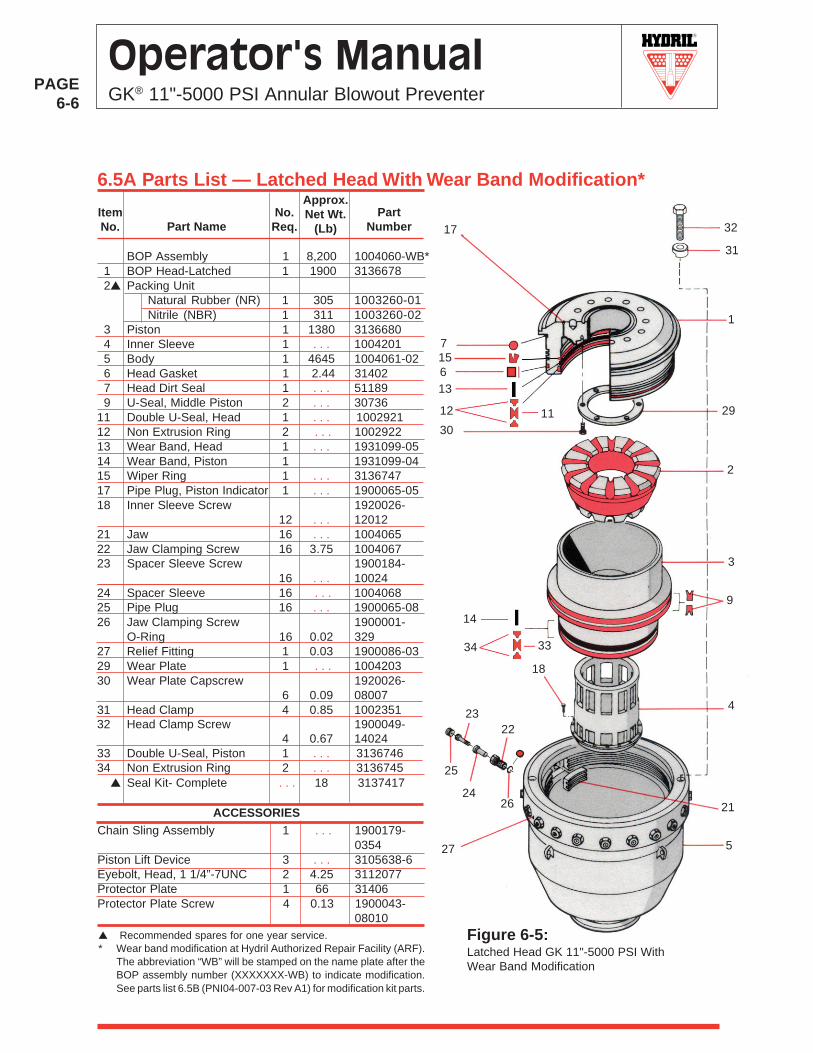
R
PAGE6-6
Operator's ManualGK® 11"-5000 PSI Annular Blowout Preventer
6.5A Parts List — Latched Head With Wear Band Modification*
Figure 6-5:Latched Head GK 11"-5000 PSI WithWear Band Modification
3
1
12
7
11 29
30
2
9
4
18
5
6
26
25
24
23
21
27
22
Approx.Net Wt.
(Lb)Part
NumberNo.
Req.Part NameItemNo. 17
13
3334
14
▲ Recommended spares for one year service.* Wear band modification at Hydril Authorized Repair Facility (ARF).
The abbreviation “WB” will be stamped on the name plate after theBOP assembly number (XXXXXXX-WB) to indicate modification.See parts list 6.5B (PNI04-007-03 Rev A1) for modification kit parts.
ACCESSORIESChain Sling Assembly 1 . . . 1900179-
0354Piston Lift Device 3 . . . 3105638-6Eyebolt, Head, 1 1/4”-7UNC 2 4.25 3112077Protector Plate 1 66 31406Protector Plate Screw 4 0.13 1900043-
08010
15
31
32
BOP Assembly 1 8,200 1004060-WB* 1 BOP Head-Latched 1 1900 3136678 2▲ Packing Unit
Natural Rubber (NR) 1 305 1003260-01Nitrile (NBR) 1 311 1003260-02
3 Piston 1 1380 3136680 4 Inner Sleeve 1 . . . 1004201 5 Body 1 4645 1004061-02 6 Head Gasket 1 2.44 31402 7 Head Dirt Seal 1 . . . 51189 9 U-Seal, Middle Piston 2 . . . 3073611 Double U-Seal, Head 1 . . . 100292112 Non Extrusion Ring 2 . . . 100292213 Wear Band, Head 1 . . . 1931099-0514 Wear Band, Piston 1 1931099-0415 Wiper Ring 1 . . . 313674717 Pipe Plug, Piston Indicator 1 . . . 1900065-0518 Inner Sleeve Screw 1920026-
12 . . . 1201221 Jaw 16 . . . 100406522 Jaw Clamping Screw 16 3.75 100406723 Spacer Sleeve Screw 1900184-
16 . . . 1002424 Spacer Sleeve 16 . . . 100406825 Pipe Plug 16 . . . 1900065-0826 Jaw Clamping Screw 1900001-
O-Ring 16 0.02 32927 Relief Fitting 1 0.03 1900086-0329 Wear Plate 1 . . . 100420330 Wear Plate Capscrew 1920026-
6 0.09 0800731 Head Clamp 4 0.85 100235132 Head Clamp Screw 1900049-
4 0.67 1402433 Double U-Seal, Piston 1 . . . 313674634 Non Extrusion Ring 2 . . . 3136745 ▲ Seal Kit- Complete . . . 18 3137417
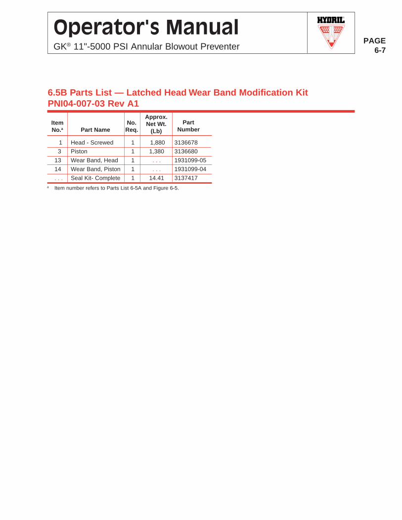
R
PAGE6-7
Operator's ManualGK® 11"-5000 PSI Annular Blowout Preventer
6.5B Parts List — Latched Head Wear Band Modification KitPNI04-007-03 Rev A1
Approx.Net Wt.
(Lb)Part
NumberNo.Req.Part Name
ItemNo.a
a Item number refers to Parts List 6-5A and Figure 6-5.
1 Head - Screwed 1 1,880 3136678
3 Piston 1 1,380 3136680
13 Wear Band, Head 1 . . . 1931099-05
14 Wear Band, Piston 1 . . . 1931099-04
. . . Seal Kit- Complete 1 14.41 3137417
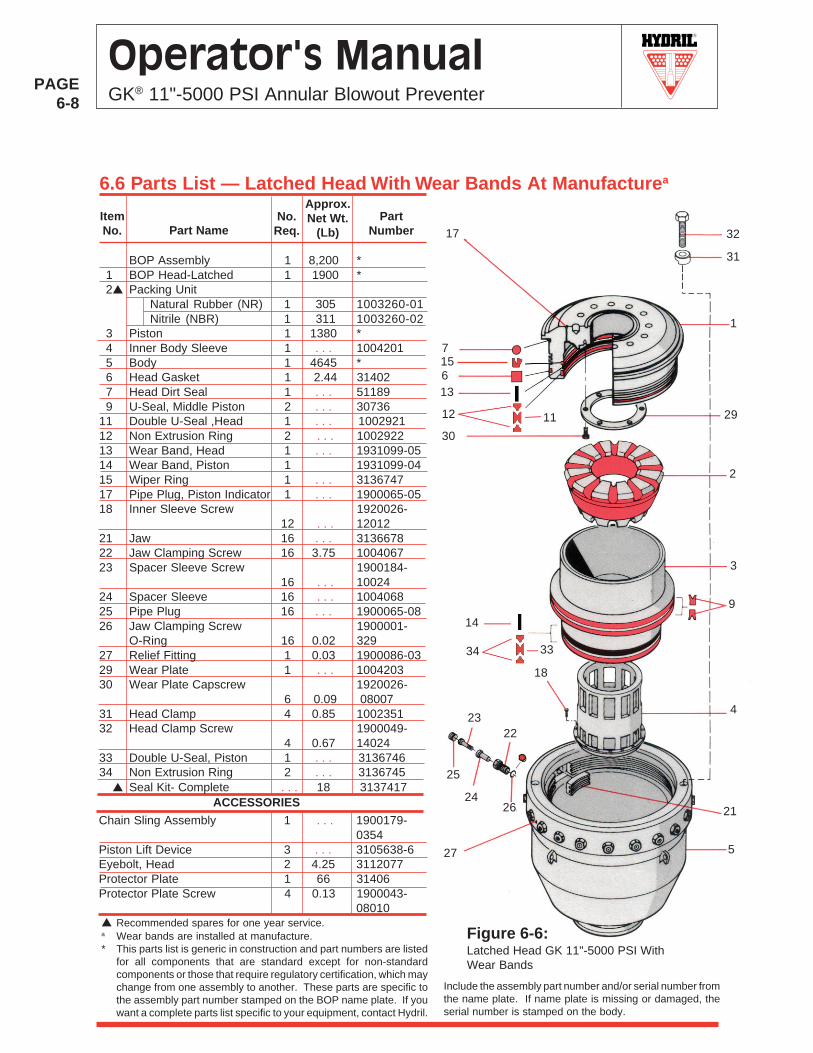
R
PAGE6-8
Operator's ManualGK® 11"-5000 PSI Annular Blowout Preventer
6.6 Parts List — Latched Head With Wear Bands At Manufacturea
Figure 6-6:Latched Head GK 11"-5000 PSI WithWear Bands
31
3
1
12
7
11 29
30
2
9
4
18
5
6
26
25
24
23
21
27
22
Approx.Net Wt.
(Lb)Part
NumberNo.
Req.Part NameItemNo. 17 32
13
3334
14
▲ Recommended spares for one year service.a Wear bands are installed at manufacture.* This parts list is generic in construction and part numbers are listed
for all components that are standard except for non-standardcomponents or those that require regulatory certification, which maychange from one assembly to another. These parts are specific tothe assembly part number stamped on the BOP name plate. If youwant a complete parts list specific to your equipment, contact Hydril.
ACCESSORIES
Chain Sling Assembly 1 . . . 1900179-0354
Piston Lift Device 3 . . . 3105638-6Eyebolt, Head 2 4.25 3112077Protector Plate 1 66 31406Protector Plate Screw 4 0.13 1900043-
08010
15
Include the assembly part number and/or serial number fromthe name plate. If name plate is missing or damaged, theserial number is stamped on the body.
BOP Assembly 1 8,200 * 1 BOP Head-Latched 1 1900 * 2▲ Packing Unit
Natural Rubber (NR) 1 305 1003260-01Nitrile (NBR) 1 311 1003260-02
3 Piston 1 1380 * 4 Inner Body Sleeve 1 . . . 1004201 5 Body 1 4645 * 6 Head Gasket 1 2.44 31402 7 Head Dirt Seal 1 . . . 51189 9 U-Seal, Middle Piston 2 . . . 3073611 Double U-Seal ,Head 1 . . . 100292112 Non Extrusion Ring 2 . . . 100292213 Wear Band, Head 1 . . . 1931099-0514 Wear Band, Piston 1 1931099-0415 Wiper Ring 1 . . . 313674717 Pipe Plug, Piston Indicator 1 . . . 1900065-0518 Inner Sleeve Screw 1920026-
12 . . . 1201221 Jaw 16 . . . 313667822 Jaw Clamping Screw 16 3.75 100406723 Spacer Sleeve Screw 1900184-
16 . . . 1002424 Spacer Sleeve 16 . . . 100406825 Pipe Plug 16 . . . 1900065-0826 Jaw Clamping Screw 1900001-
O-Ring 16 0.02 32927 Relief Fitting 1 0.03 1900086-0329 Wear Plate 1 . . . 100420330 Wear Plate Capscrew 1920026-
6 0.09 0800731 Head Clamp 4 0.85 100235132 Head Clamp Screw 1900049-
4 0.67 1402433 Double U-Seal, Piston 1 . . . 313674634 Non Extrusion Ring 2 . . . 3136745 ▲ Seal Kit- Complete . . . 18 3137417
R
PAGE6-9
Operator's ManualGK® 11"-5000 PSI Annular Blowout Preventer
"Maintenance and Testing" for testing procedures.NOTE: For additional discussion on operating fluidand specific fluid recommendations, refer to HydrilEngineering Bulletin EB9909A on Hydril Websitewww.hydril.com.
3. Drain the bore and rinse thoroughly behind the pack-ing unit and inner sleeve with water displacement oil.
4. Drain the operating fluid and flush out the operatingfluid paths and chambers (Open and Close) with waterdisplacing oil.
5. Allow the bore, operating fluid paths and chambers(Open and Close) to dry.
6. Install pipe plugs into Open and Close ports.7. Apply Cortec VCI 369 grease to bottom connection
mating surface .8. Install a protective cover on the bottom connection.
Ensure that a tight seal exists between the BOP andthe cover. Use silicone cauk if necessary.
9. Drop 10 ounces of Cortec VCI 609 vapor phasecorrosion inhibitor into the bore of the BOP.
10. Apply Cortec VCI 369 grease to the top connectionmating surface.
11. Install a protective cover on the top connection. En-sure that a tight seal exists between the BOP and thecover. Use silicone cauk if necessary.
12. Touch up paint where necessary. Contact Hydril forpaint specifications.
13. Coat unpainted exterior surfaces with Cortec VCI 369grease.
6.7.2 Depreservation Procedure and Return to ServiceRemove the end connection covers and blow or rinse outthe vapor phase corrosion inhibitor.
6.7 Preventer StorageThe following preservation procedure protects the Hydril®
11 5/8"-5000 PSI annular BOP for up to two years ofstorage. The protection period is dependent primarily uponthe sealing integrity of the end connections and sealing ofother pressure boundary penetrations.
6.7.1 Preservation Procedure
A. Materials Required1. Cortec VCI 369 grease (for unpainted machined face
surfaces)2. Cortec VCI 609 vapor phase corrosion inhibitor, 10
ounce (for bore and exposed interior surfaces)3. Two protective covers for the end connections.4. Water displacement oil such as Hougton Rust Veto
4221 or Stack Guard 180; Witco Macco 1961; or anyAW Hydraulic Oil 46 (required for removal of waterafter hydrostatic testing)
5. One tube of silicone caulk (additional sealing forprotective covers)
B. Procedure1. Disassemble, clean, inspect, lubricate, and assemble
the annular BOP. Refer to the maintenance procedurein Section 4, "Maintenance and Testing" and Section5, "Disassembly and Assembly." Replacement ofworn packing units, seals, and other parts can bemade conveniently at this time. Hydril recommendsthe replacement of all seals when the annular BOP isdisassembled.
2. Test the packing unit and seals, using a 50/50 mix offresh water (DO NOT USE SEA WATER OR BRINE)and glycol mixed with corrosion inhibitor or BOP hy-draulic fluid as an operating fluid. Refer to Section 4,
R
PAGE6-10
Operator's ManualGK® 11"-5000 PSI Annular Blowout Preventer
6.8 Rubber Goods StorageThe term rubber goods includes synthetic compoundssuch as Nitrile Copolymers and Neoprene, as well asnatural rubber parts. The ideal storage situation forrubber goods would be in air tight containers maintainedin a cool, dry, dark storage area.
The following recommendations will allow vendorsand users of oil field equipment to maximize normallyavailable storage facilities for rubber goods:1. Keep the rubber storage area as dark as possible —
preferably indoors, not outdoors, and away fromdirect sunlight, skylights, windows, and direct artifi-cial lighting.
2. Select a cool location (approximately 65oF) that isaway from heaters, stoves, and direct blasts ofspace heaters.
3. Keep rubber goods away from electrical machinery
(motors, switch gear, or any high voltage equipment produc-ing corona and ozone). Avoid locations susceptible to draftsthat will carry the atmosphere from electrical machinery tothe rubber goods storage area.
4. The practice of first-in, first-out is essential with rubbergoods.
5. Store rubber goods in a relaxed position in their normalshape. For example, do not hang O-rings on nails. Do notkeep assemblies in stretched attitudes, e.g., O-rings onglands, BOP testers, and operator parts.
6. Rubber goods storage areas should be kept as dry aspossible. Remove oil, grease or other foreign materials fromthe storage area to preclude spillage on rubber goods.
7. If storage for extended periods is anticipated, sealed con-tainers are recommended. Impervious surface coveringssuch as waxing will increase shelf life.
OP
ER
ATO
R'S
MA
NU
AL
R
Pressure Control Equipment


