61
Hydro-elastoplastic analysis of floating plate structures 1 Joo-Seong Yoon Mechanical Engineering 14, November, 2016 Ph. D. Thesis Presentation
Hydro-elastoplastic analysis offloating plate structures
1
Joo-Seong Yoon
Mechanical Engineering14, November, 2016
Ph. D. Thesis Presentation
Contents
2
1. Introduction
2. Hydroelastic analysis of floating plate structures
3. Consideration of multiples hinge connections
4. Hydro-elastoplastic analysis of floating plate structures
5. Conclusions & future works
3
Introduction
Introduction to hydrodynamic analysis Brief history Methods for hydroelastic analysis Related problems and studies Research problems

Introduction to hydrodynamic analysis
4
Complexity Size Risk
Resources Space
Design of floating structures
Offshore market demands
Importance of hydrodynamic analysis offloating structures has been increasing
Figure source : google image

Introduction to hydrodynamic analysis
5Floating structure - wave interaction is a key topic
Video source : YouTube
Hirdaris et al., Loads for use in the design of ships and offshore structures. Ocean Eng 2014;78:131-74.
Research development activities (2009~2012)
Introduction to hydrodynamic analysis
6
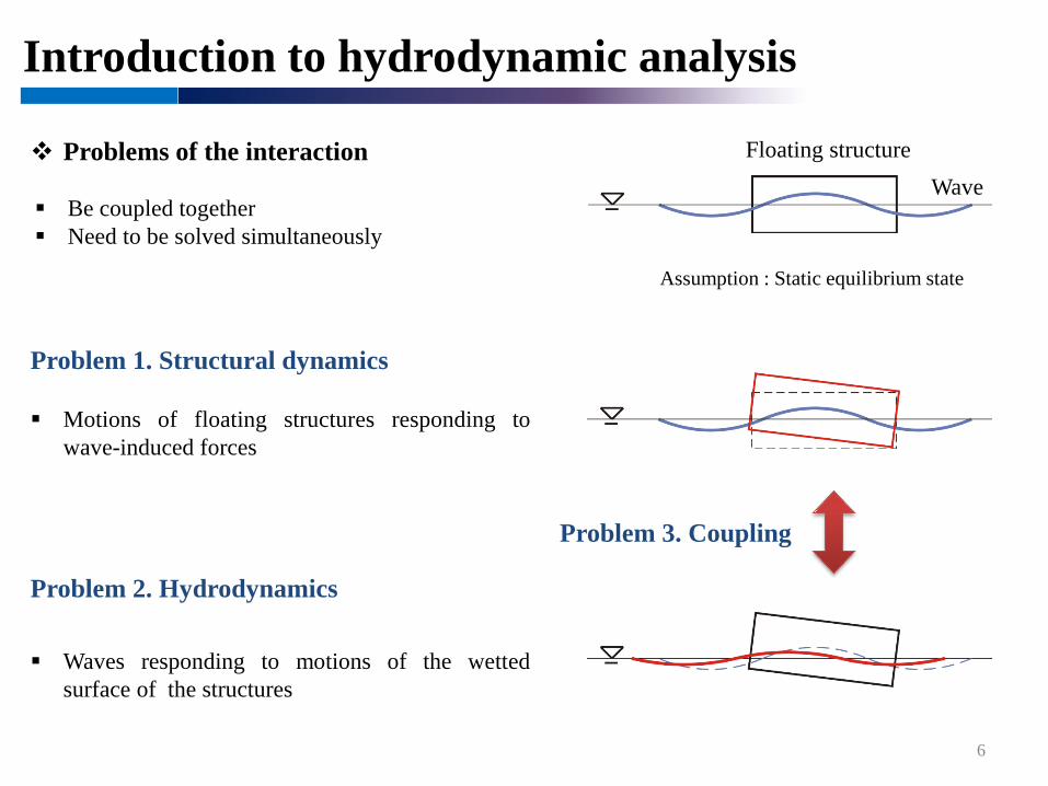
Be coupled together Need to be solved simultaneously
Floating structureWave
Problem 1. Structural dynamics
Problem 2. Hydrodynamics
Waves responding to motions of the wettedsurface of the structures
Problems of the interaction
Motions of floating structures responding towave-induced forces
Assumption : Static equilibrium state
Problem 3. Coupling
Brief history
7
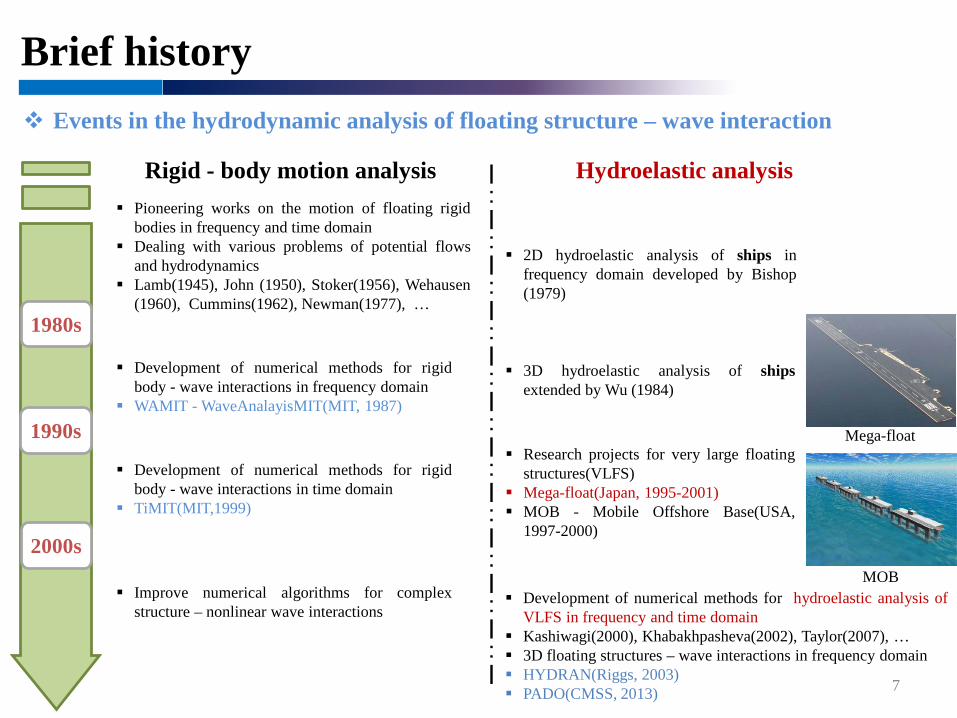
Events in the hydrodynamic analysis of floating structure – wave interaction
1980s
1990s
2000s
Rigid - body motion analysis Hydroelastic analysis Pioneering works on the motion of floating rigid
bodies in frequency and time domain Dealing with various problems of potential flows
and hydrodynamics Lamb(1945), John (1950), Stoker(1956), Wehausen
(1960), Cummins(1962), Newman(1977), …
Development of numerical methods for rigidbody - wave interactions in frequency domain
WAMIT - WaveAnalayisMIT(MIT, 1987)
Development of numerical methods for rigidbody - wave interactions in time domain
TiMIT(MIT,1999)
Improve numerical algorithms for complexstructure – nonlinear wave interactions
2D hydroelastic analysis of ships infrequency domain developed by Bishop(1979)
3D hydroelastic analysis of shipsextended by Wu (1984)
Research projects for very large floatingstructures(VLFS)
Mega-float(Japan, 1995-2001) MOB - Mobile Offshore Base(USA,
1997-2000)
Development of numerical methods for hydroelastic analysis ofVLFS in frequency and time domain
Kashiwagi(2000), Khabakhpasheva(2002), Taylor(2007), … 3D floating structures – wave interactions in frequency domain HYDRAN(Riggs, 2003) PADO(CMSS, 2013)
Mega-float
MOB

Methods for hydroelastic analysis
Floating Airport
8
Floating elastic plate structure – wave interactions
Considerations in the analysis
Elastic deformations are more important than rigid body motions Hydroelastic analyses should be performed to accurately predict
the bending moment and deflection The VLFSs have mainly been modeled as thin elastic plate
structures
Floating Bridge
Features of pontoon-type VLFSs
Huge horizontal size compared to the wavelengths Relatively small bending rigidity
Methods for hydroelastic analysis
9
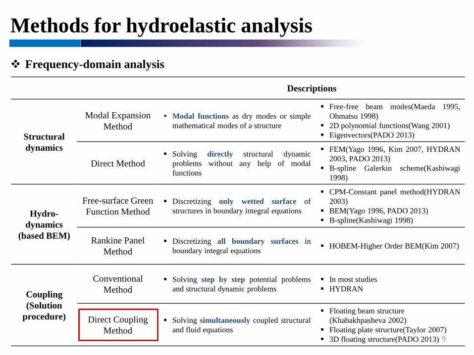
Frequency-domain analysis
Descriptions
Structural dynamics
Modal Expansion Method
Modal functions as dry modes or simplemathematical modes of a structure
Free-free beam modes(Maeda 1995,Ohmatsu 1998)
2D polynomial functions(Wang 2001) Eigenvectors(PADO 2013)
Direct Method Solving directly structural dynamic
problems without any help of modalfunctions
FEM(Yago 1996, Kim 2007, HYDRAN2003, PADO 2013)
B-spline Galerkin scheme(Kashiwagi1998)
Hydro-dynamics
(based BEM)
Free-surface Green Function Method
Discretizing only wetted surface ofstructures in boundary integral equations
CPM-Constant panel method(HYDRAN2003)
BEM(Yago 1996, PADO 2013) B-spline(Kashiwagi 1998)
Rankine Panel Method
Discretizing all boundary surfaces inboundary integral equations HOBEM-Higher Order BEM(Kim 2007)
Coupling(Solution
procedure)
Conventional Method
Solving step by step potential problemsand structural dynamic problems
In most studies HYDRAN
Direct Coupling Method
Solving simultaneously coupled structuraland fluid equations
Floating beam structure (Khabakhpasheva 2002)
Floating plate structure(Taylor 2007) 3D floating structure(PADO 2013)
Methods for hydroelastic analysis
10
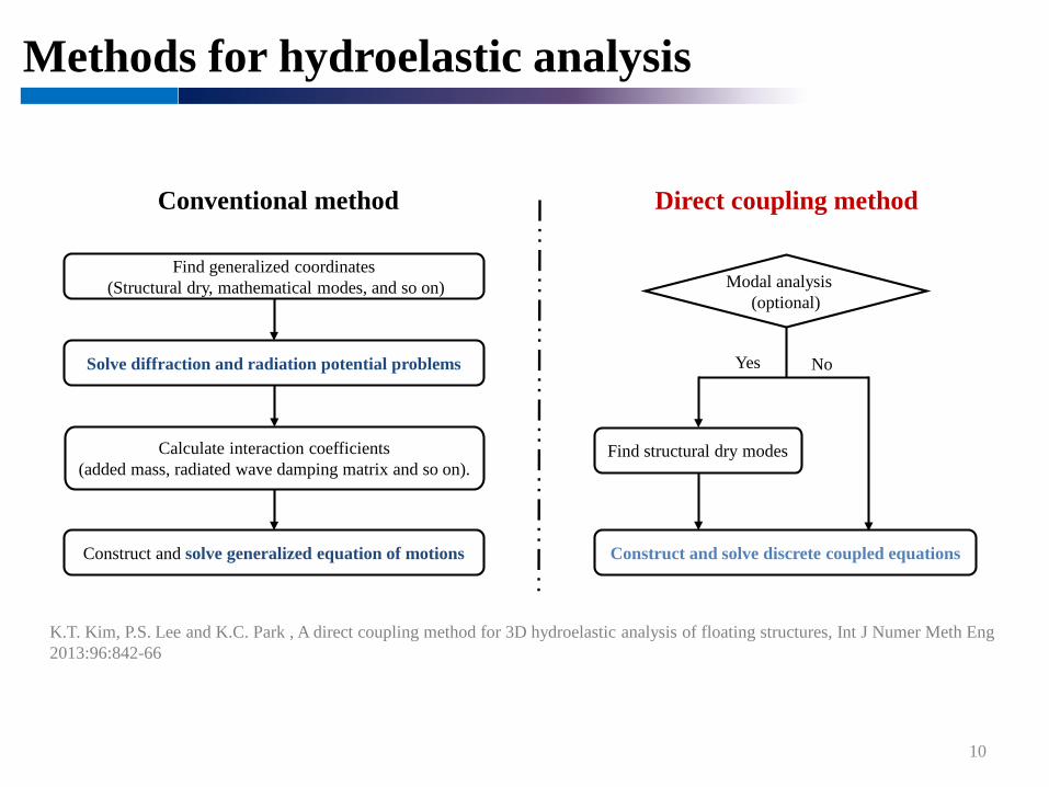
Conventional method
K.T. Kim, P.S. Lee and K.C. Park , A direct coupling method for 3D hydroelastic analysis of floating structures, Int J Numer Meth Eng2013:96:842-66
Direct coupling method
Modal analysis(optional)
Yes No
Find generalized coordinates(Structural dry, mathematical modes, and so on)
Solve diffraction and radiation potential problems
Calculate interaction coefficients (added mass, radiated wave damping matrix and so on).
Construct and solve generalized equation of motions
Find structural dry modes
Construct and solve discrete coupled equations
Methods for hydroelastic analysis
11
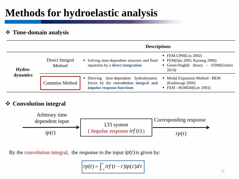
Time-domain analysis
Descriptions
Hydro-dynamics
Direct Integral Method
Solving time-dependent structure and fluidequations by a direct integration
FEM-CPM(Liu 2002) FEM(Qiu 2005, Kyoung 2006) Green-Naghdi theory – FDM(Ertekin
2014)
Cummins Method Deriving time-dependent hydrodynamic
forces by the convolution integral andimpulse response functions
Modal Expansion Method - BEM (Kashiwagi 2000)
FEM - HOBEM(Lee 2003)
Arbitrary time dependent input Corresponding response
Convolution integral
)(trp
)(tip
LTI system( Impulse response ))(tirf
By the convolution integral, the response to the input is given by:
∫∞
∞−−= τττ diptirftrp )()()(
)(tip
Methods for hydroelastic analysis
12
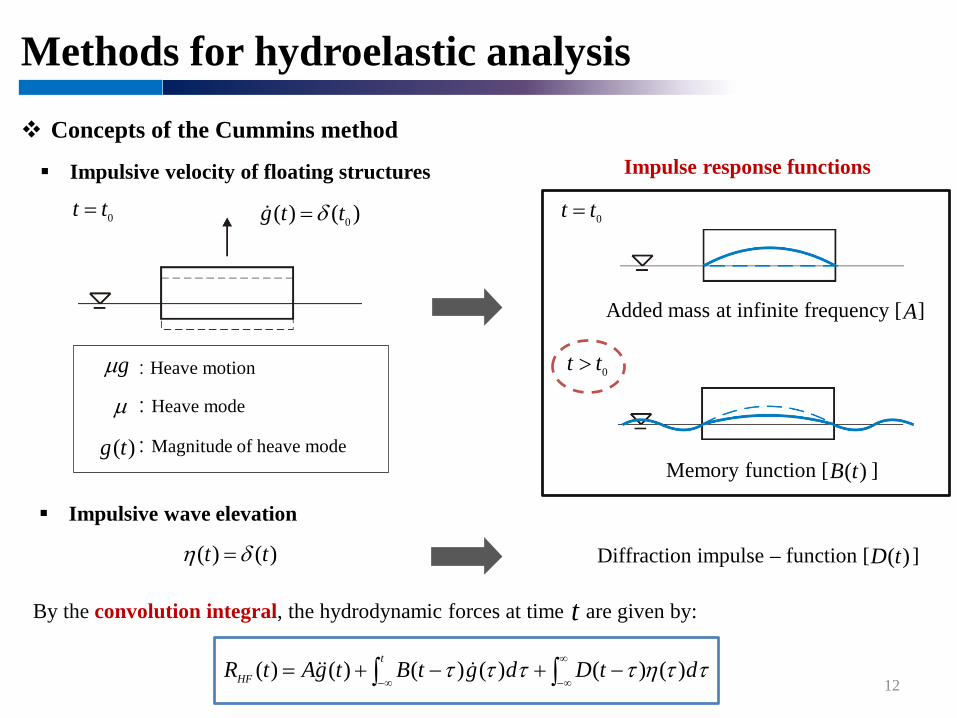
Concepts of the Cummins methodImpulse response functions
Added mass at infinite frequency [ ]
Memory function [ ]
By the convolution integral, the hydrodynamic forces at time are given by: t
: Heave motion
: Heave mode
: Magnitude of heave mode
Impulsive velocity of floating structures
)()( 0ttg δ=0tt = 0tt =
0tt >gµ
µ
)(tg
A
)(tB
Impulsive wave elevation
)()( tt δη = Diffraction impulse – function [ ])(tD
∫∫∞
∞−∞−−+−+= ττηττττ dtDdgtBtgAtR
t
HF )()()()()()(
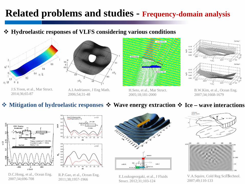
Related problems and studies - Frequency-domain analysis
13
Hydroelastic responses of VLFS considering various conditions
Mitigation of hydroelastic responses Ice – wave interactions Wave energy extraction
A.I.Andrianov, J Eng Math. 2006;54;31-48
J.S.Yoon, et al., Mar Struct. 2014;36;65-87
H.Seto, et al., Mar Struct. 2005;18;181-2000
B.W.Kim, et al., Ocean Eng. 2007;34;1668-1679
D.C.Hong, et al., Ocean Eng. 2007;34;696-708
R.P.Gao, et al., Ocean Eng. 2011;38;1957-1966
E.Loukogeorgaki, et al., J Fluids Struct. 2012;31;103-124
V.A.Squire, Cold Reg Sci Technol. 2007;49;110-133

Related problems and studies - Time-domain analysis
14
Effect of aircraft landing on and taking off from VLFS
Nonlinear effects of a mooring system or nonlinear waves
Solitary wave Cnoidal wave
M.Kashiwagi, J Mar Sci Technol. 2004;9;14-23
E.Watanabe, et al., Eng Struct. 2004;26;245-256
J.H.Kyoung, et al., 17th ISOPE. 2007;1;231-236
X.Liu, et al., J Eng Mech. 2002;128;48-56
R.C.Ertekin, et al., PhysFluids. 2014;26;027101
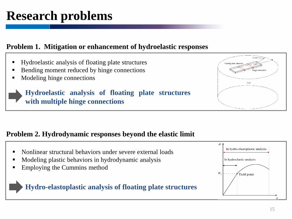
Research problems
15
Problem 1. Mitigation or enhancement of hydroelastic responses
Hydroelastic analysis of floating plate structures Bending moment reduced by hinge connections Modeling hinge connections
Problem 2. Hydrodynamic responses beyond the elastic limit
Nonlinear structural behaviors under severe external loads Modeling plastic behaviors in hydrodynamic analysis Employing the Cummins method
Hydroelastic analysis of floating plate structureswith multiple hinge connections
Hydro-elastoplastic analysis of floating plate structures
16
Hydroelastic analysis of floating plate structures
Formulation of floating plate structures
Formulation of fluid
Matrix formulation of coupled equations
Formulation of floating plate structures
17
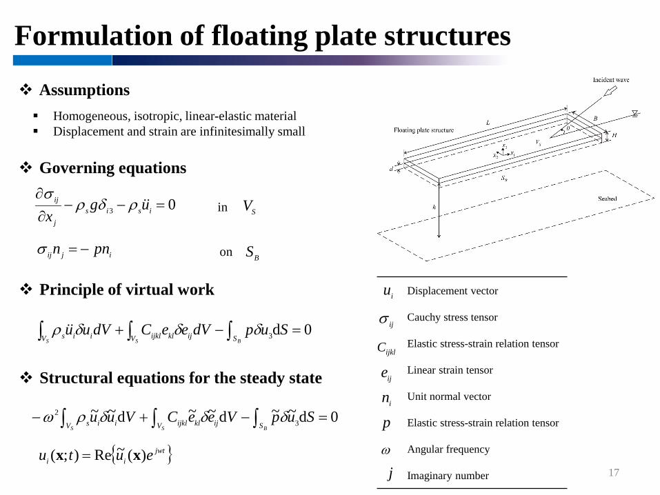
Assumptions Homogeneous, isotropic, linear-elastic material Displacement and strain are infinitesimally small
Governing equations
0 3 =−−∂∂
isisj
ij ugx
ρδρσ
in SV
ijij pnn −=σ on BS
iu
pin
ijklC
ije
ijσ
Principle of virtual work
0d 3 =−+ ∫∫∫
BSS SV ijklijklV iis SupdVeeCdVuu δδδρ
Structural equations for the steady state
{ }jwtii eutu )(~Re);( xx =
0d~~ d~~d~~ 3
2 =−+− ∫∫∫BSS SV ijklijklV iis SupVeeCVuu δδδρω
Displacement vector
Cauchy stress tensor
Elastic stress-strain relation tensor
Linear strain tensor
Unit normal vector
Elastic stress-strain relation tensor
Angular frequency
Imaginary number
ω
j

Formulation of fluid
18
Assumptions Incompressible, inviscid and irrotational flow Amplitude is small Draft is zero
Governing equations
0~2 =∇ φ in VS
on SFφωφ ~ ~ 2
3 gx=
∂∂ for 03 =x
0 ~
3
=∂∂xφ on SG
( ) 0 ~~ =−
+∂∂
IjkR
R φφ on )( ∞→∞ RS
3
~uj
nωφ
−=∂∂
on SB
{ }tjet ωφφ )(~Re);( xx =
2∇
Iφφ Velocity potential
Incident wave potential
Laplace operator
Wave numberk
Formulation of fluid
19
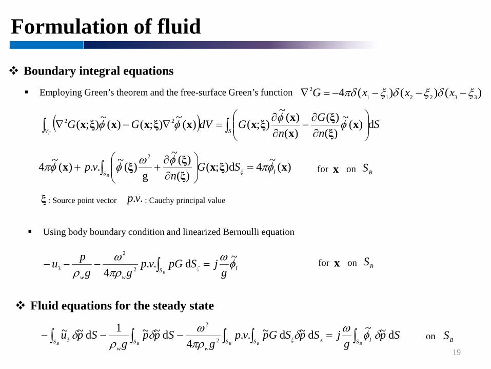
Boundary integral equations
Employing Green’s theorem and the free-surface Green’s function
ξ
Spg
jSpSGpvpg
Sppg
SpuBB BBB S IS xS
wS
wS
d ~ ~d ~d ~..4
d ~~1d ~ ~2
2
3 ∫∫ ∫∫∫ =−−− δφωδπρωδ
ρδ ξ
)(~4d);()()(~
g)(~..)(~4
2
xξxξξξx IS
SGn
vpB
φπφωφφπ ξ =
∂∂
++ ∫ on SBfor x
Using body boundary condition and linearized Bernoulli equation
)()()(4 3322112 ξδξδξπδ −−−−=∇ xxxG
ISww g
jSpGvpgg
puB
φωπρω
ρ ξ
~d ..4 2
2
3 =−−− ∫ on SBfor x
Fluid equations for the steady state
on SB
: Source point vector ..vp : Cauchy principal value
( ) SnG
nGdVGG
SVF∫∫
∂∂
−∂∂
=∇−∇ d)(~)()(
)()(~
);()(~);()(~);( 22 xξξ
xxξxxξxxξx φφφφ

Matrix formulation of coupled equations
20
Coupled equations
Spg
jSpSGpvpg
Sppg
SpuBB BBB S IS xS
wS
wS
d ~ ~d ~d ~..4
d ~~1d ~ ~2
2
3 ∫∫ ∫∫∫ =−−− δφωδπρωδ
ρδ ξ
Matrix formulation for a hydroelasitc analysis in frequency domain
0d~~ d~~d~~ 3
2 =−+− ∫∫∫BSS SV ijklijklV iis SupVeeCVuu δδδρω
Discretization of the structural and fluid equations by FEM and BEM 4-node MITC plate finite element 4-node quadrilateral boundary element
=
−−−
−+−
IR0
pu
FFCCSS
ˆˆˆ 2
GMT
up
upKMω

21
Consideration of multiple hinge connections
Motivation Previous studies Research description Modeling hinge connections Dimensionless quantities Validation Numerical analyses Closure

Motivation
22
No hinge
1 hinge
2 hinge
When using more hinge connections,
For the design of a floating airport or an wave energy converter,
Hydroelastic responses of floating plate structures with multiple hinge connections
However, the deflection could be increased, and vice versa.the bending moment of cross sections can be effectively reduced.
hinge connections can be helpful or harmful.

Previous studies
23S. Fu et al
C.H. Lee, J.N. Newman
Development of modeling methods of hinge connections in the conventional method
Numerically evaluation for complicated problemsS. Fu et al., Ocean. Eng. 2007;34;1516-31R.P. Gao et al, Ocean. Eng. 2011; 38 1957-66E. Loukogeorgaki et al., J Fluid Struct, 2012;31;103-24
Analytically evaluation for simple problemsC.H. Lee, J.N. Newman, J Fluid Struct, 2000;14;957-70J.N. Newman, Mar Struct, 2005;16; 169-180
Constraints enforced by penalty technique
Modification of the equation of motion B.W. Kim et al., 15th ISOPE, 2005; 210-17
Hinge deflection modes Hinge deflection modes
The effect of the number of hinge connections has notbeen studied well
Reducing hydroelastic responsesGao(2011) – 1 hinge, position, wave angle, length and depth, plate’s aspect ratioKim(2005) – 2 hinges, hinge-linked stiffness and shape of breakwaters, wave length
Enhancing hydroelastic responsesLoukogeorgaki(2012) – 1hinge, position, wave angle and length
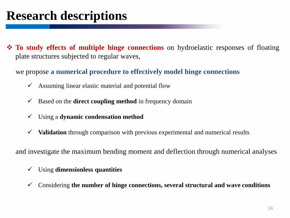
Research descriptions
Assuming linear elastic material and potential flow
Based on the direct coupling method in frequency domain
Using a dynamic condensation method
Validation through comparison with previous experimental and numerical results
24
we propose a numerical procedure to effectively model hinge connections
and investigate the maximum bending moment and deflection through numerical analyses
To study effects of multiple hinge connections on hydroelastic responses of floatingplate structures subjected to regular waves,
Using dimensionless quantities
Considering the number of hinge connections, several structural and wave conditions
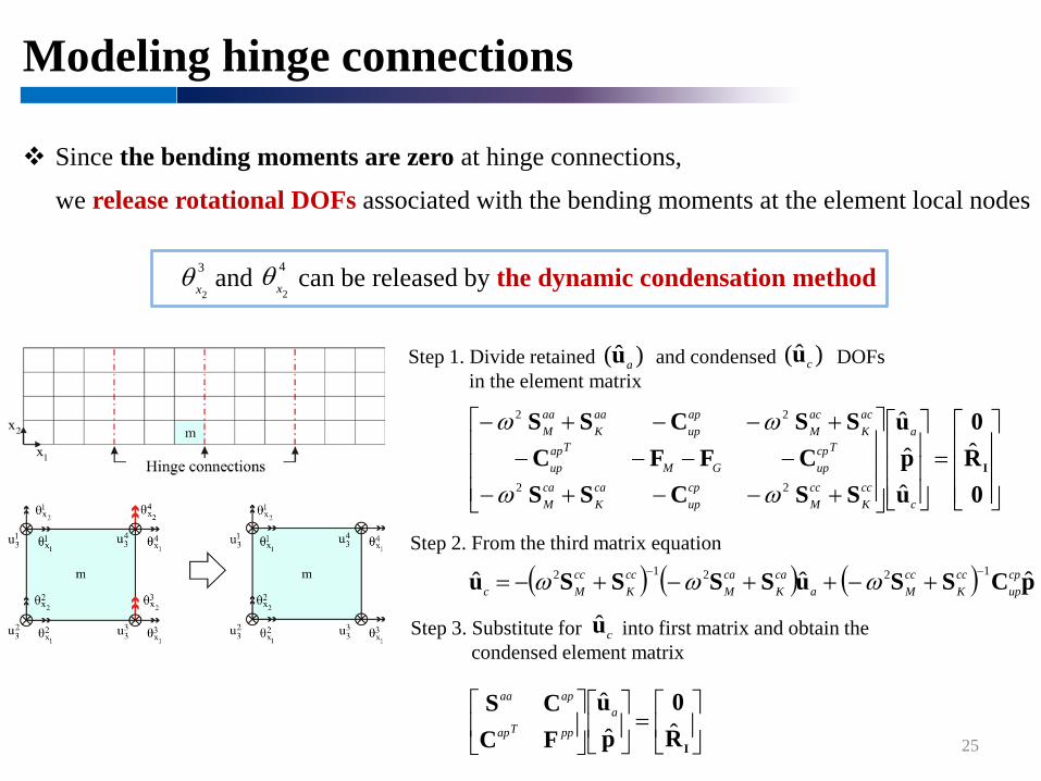
Modeling hinge connections
25
Since the bending moments are zero at hinge connections,
we release rotational DOFs associated with the bending moments at the element local nodes
and can be released by the dynamic condensation method2
4
xθ2
3
xθ
Step 1. Divide retained and condensed DOFs in the element matrix
Step 2. From the third matrix equation
Step 3. Substitute for into first matrix and obtain thecondensed element matrix
=
IR0
pu
FCCS
ˆˆˆ a
ppTap
apaa
)ˆ( au )ˆ( cu
( ) ( ) ( ) pCSSuSSSSu ˆˆˆ 12212 cpup
ccK
ccMa
caK
caM
ccK
ccMc
−− +−++−+−= ωωω
cu
=
+−−+−−−−−
+−−+−
0R0
upu
SSCSSCFFC
SSCSS
Iˆ
ˆˆˆ
22
22
c
a
ccK
ccM
cpup
caK
caM
TcpupGM
Tapup
acK
acM
apup
aaK
aaM
ωω
ωω
Dimensionless quantities
26
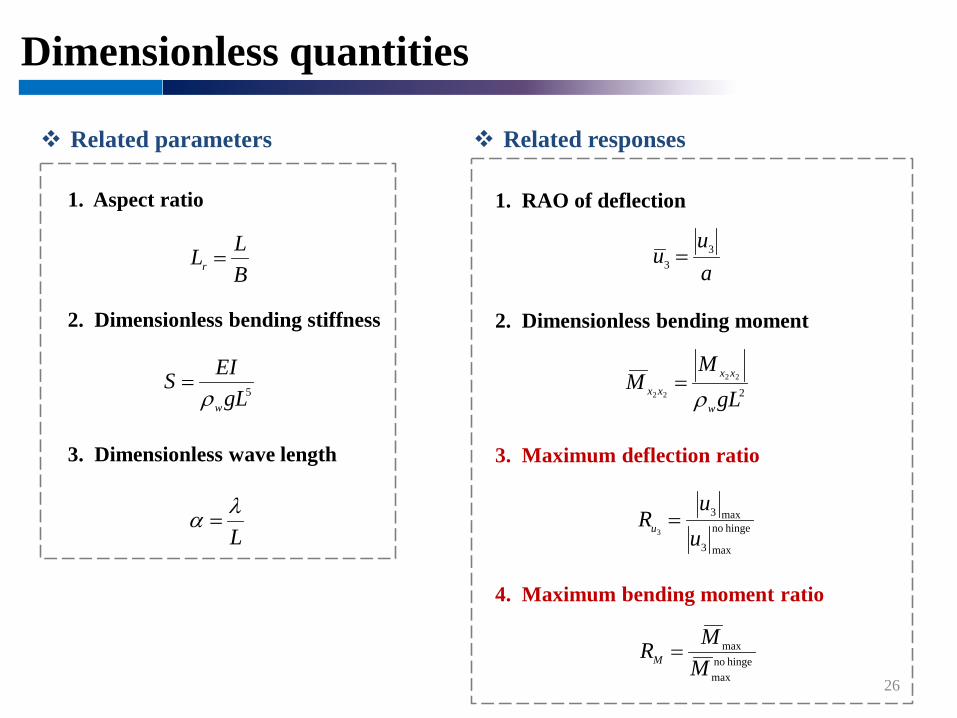
Related parameters
1. Aspect ratio
BLLr =
2. Dimensionless bending stiffness
Lλα =
3. Dimensionless wave length
5gLEISwρ
=
Related responses
1. RAO of deflection
2. Dimensionless bending moment
4. Maximum bending moment ratio
au
u 33 =
222
22 gLM
Mw
xxxx ρ=
hinge nomax
max
MMRM =
3. Maximum deflection ratio
hinge no
max3
max3
3 uu
Ru =
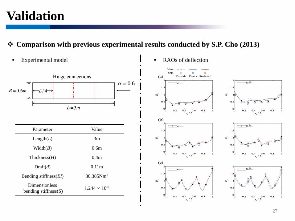
Validation
27
Comparison with previous experimental results conducted by S.P. Cho (2013)
Experimental model
Parameter Value
Length(L) 3m
Width(B) 0.6m
Thickness(H) 0.4m
Draft(d) 0.11m
Bending stiffness(EI) 30.385Nm2
Dimensionlessbending stiffness(S) 1.244 × 10⁻⁵
RAOs of deflection
6.0=α
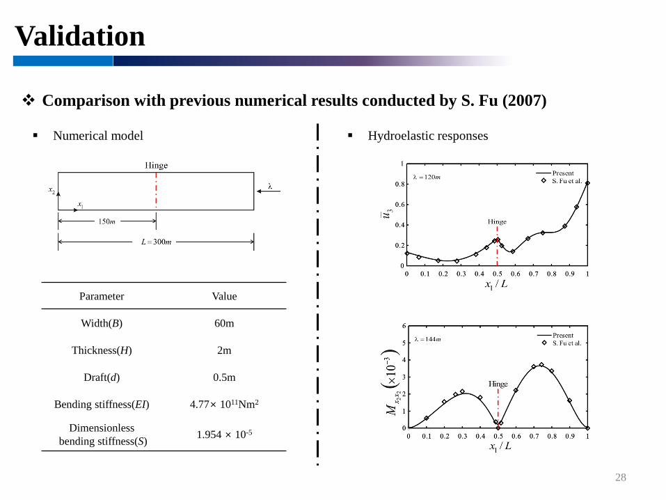
Validation
28
Comparison with previous numerical results conducted by S. Fu (2007)
Numerical model Hydroelastic responses
Parameter Value
Width(B) 60m
Thickness(H) 2m
Draft(d) 0.5m
Bending stiffness(EI) 4.77× 10¹¹Nm2
Dimensionlessbending stiffness(S) 1.954 × 10⁻⁵
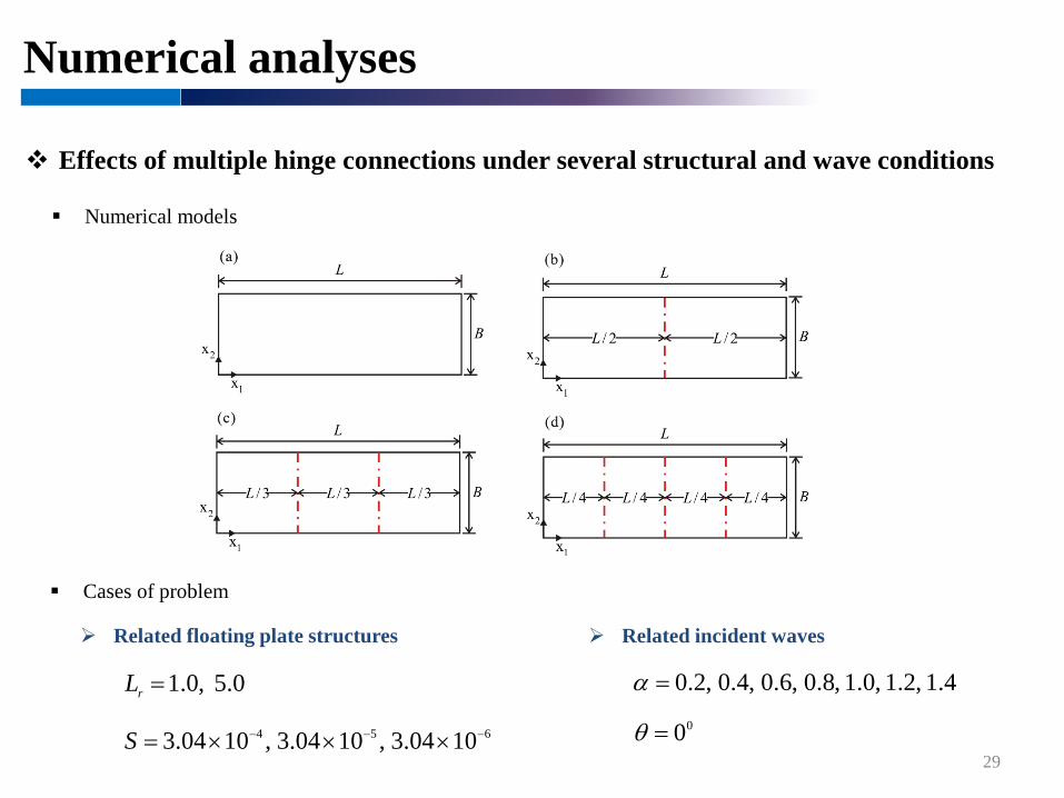
Numerical analyses
29
Effects of multiple hinge connections under several structural and wave conditions
Numerical models
Cases of problem
Related floating plate structures Related incident waves
0.5,0.1=rL
654 1004.3,1004.3,1004.3 −−− ×××=S00=θ
4.1,2.1,0.1,8.0,6.0,4.0,2.0=α
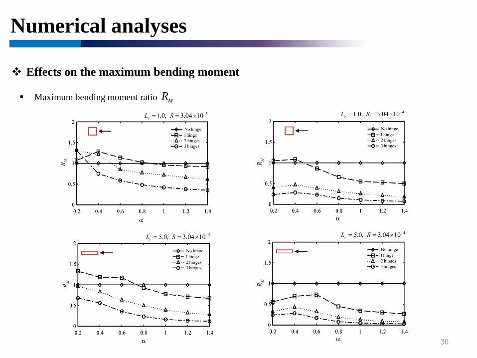
Numerical analyses
30
Effects on the maximum bending moment
Maximum bending moment ratio MR
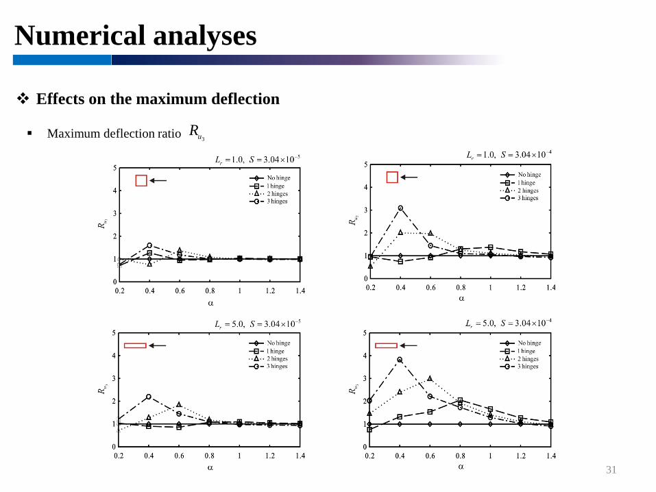
Numerical analyses
31
Effects on the maximum deflection
Maximum deflection ratio 3uR
Numerical analyses
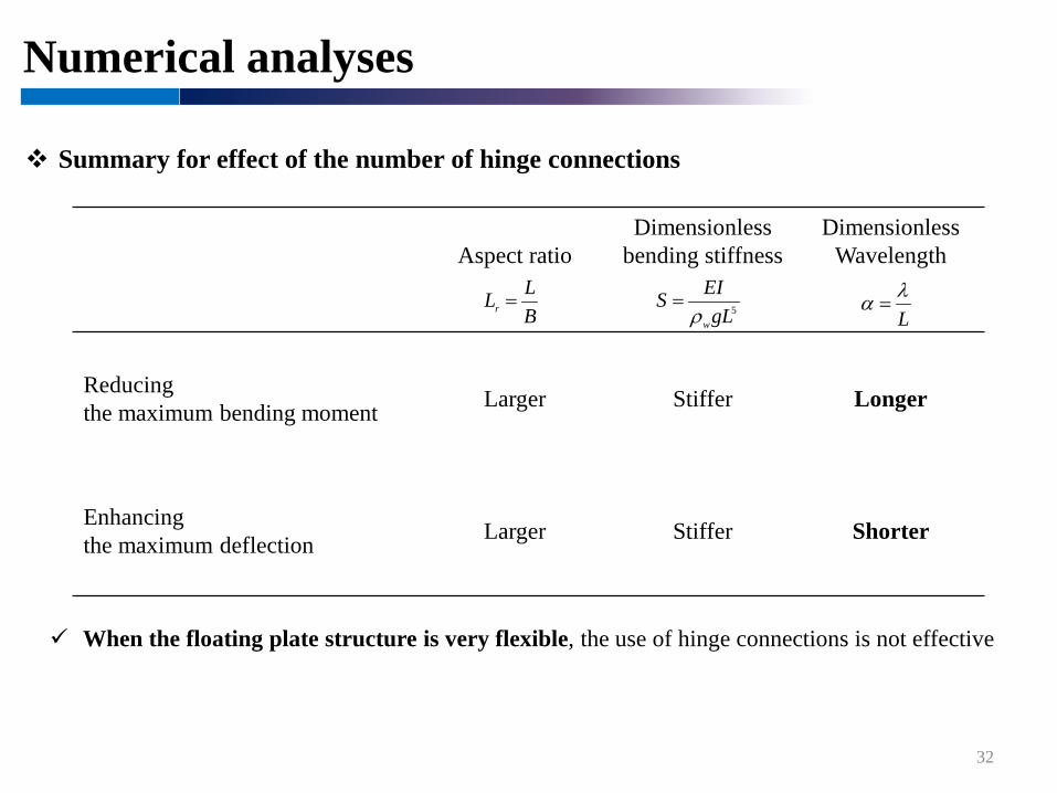
32
Summary for effect of the number of hinge connections
Aspect ratioDimensionless
bending stiffnessDimensionless
Wavelength
Reducingthe maximum bending moment Larger Stiffer Longer
Enhancingthe maximum deflection Larger Stiffer Shorter
When the floating plate structure is very flexible, the use of hinge connections is not effective
BLLr =
Lλα =5gL
EISwρ
=

33
Hydro-elastoplastic analysis of floating plate structures
Motivation Previous studies Research descriptions Structural dynamics associated with material nonlinearity Hydrodynamics in the time domain Floating plate structure – wave interactions Numerical procedure Validation Numerical examples
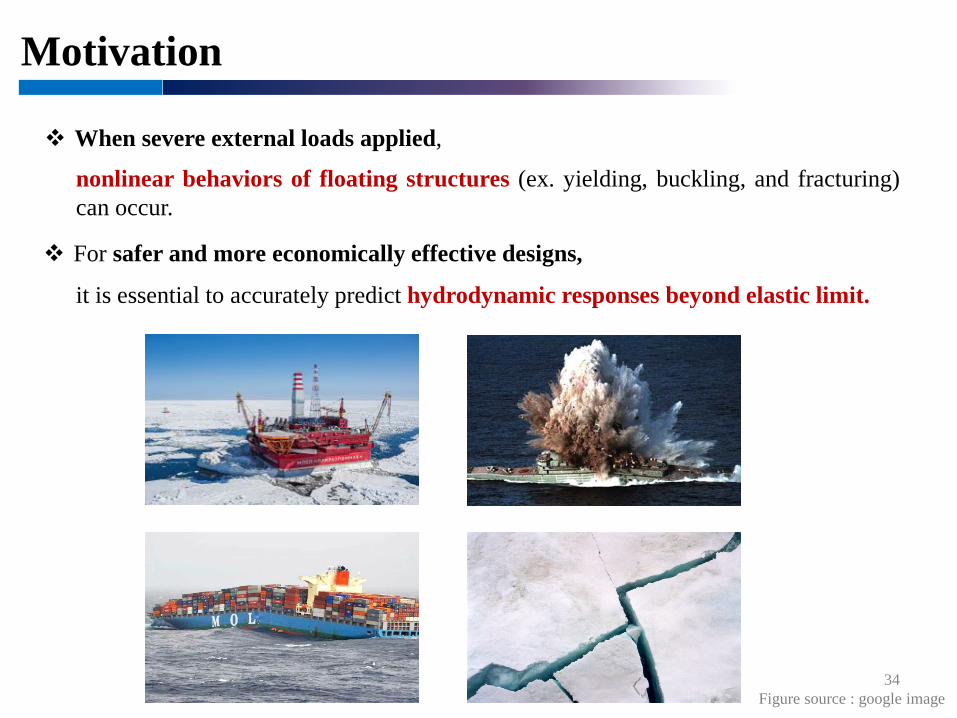
Motivation
34
When severe external loads applied,
nonlinear behaviors of floating structures (ex. yielding, buckling, and fracturing)can occur.
For safer and more economically effective designs,
it is essential to accurately predict hydrodynamic responses beyond elastic limit.
Figure source : google image
Previous studies
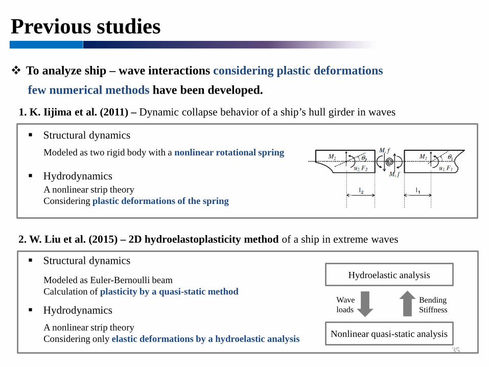
1. K. Iijima et al. (2011) – Dynamic collapse behavior of a ship’s hull girder in waves
2. W. Liu et al. (2015) – 2D hydroelastoplasticity method of a ship in extreme waves
Hydrodynamics
35
To analyze ship – wave interactions considering plastic deformationsfew numerical methods have been developed.
A nonlinear strip theoryConsidering plastic deformations of the spring
Structural dynamicsModeled as two rigid body with a nonlinear rotational spring
Structural dynamics
Modeled as Euler-Bernoulli beamCalculation of plasticity by a quasi-static method
HydrodynamicsA nonlinear strip theoryConsidering only elastic deformations by a hydroelastic analysis Nonlinear quasi-static analysis
Hydroelastic analysis
BendingStiffness
Waveloads

Previous studies
M. Fujikubo (2005) – Structural analysis for the design of VLFS
36
Few researches related to nonlinear behaviors of VLFS have been conducted.
Structural analysis is performed by two-step approach
Step 1. Hydroelastic analysis
Step 2. Nonlinear quasi-static analysis
It is difficult to accurately predict hydro-elastoplastic responses for floatingplate structures in waves through previous methods
Hydroelastic analysis
Nonlinear quasi-static analysis
Waveloads
considering the calculated hydroelastic responses
Research descriptions
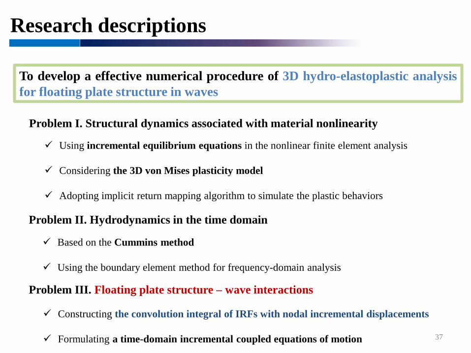
To develop a effective numerical procedure of 3D hydro-elastoplastic analysisfor floating plate structure in waves
Problem II. Hydrodynamics in the time domain
Problem I. Structural dynamics associated with material nonlinearity
Problem III. Floating plate structure – wave interactions
Constructing the convolution integral of IRFs with nodal incremental displacements
Formulating a time-domain incremental coupled equations of motion 37
Based on the Cummins method
Using the boundary element method for frequency-domain analysis
Using incremental equilibrium equations in the nonlinear finite element analysis
Considering the 3D von Mises plasticity model
Adopting implicit return mapping algorithm to simulate the plastic behaviors
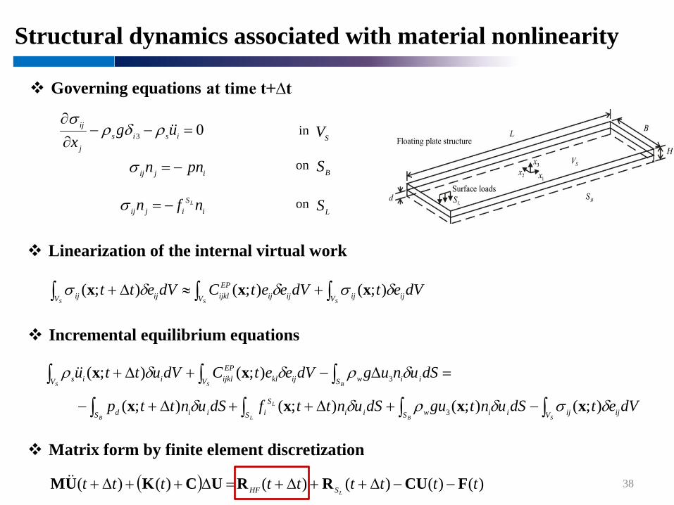
Structural dynamics associated with material nonlinearity
38
Governing equations
in
on
on
Incremental equilibrium equations
=∆−+∆+ ∫ ∫∫S BS V S iiwijkl
EPijklV iis dSunugdVeetCdVuttu δρδδρ 3);();( xx
∫∫∫∫ −+∆++∆+−SBL
L
B V ijijS iiwS iiS
iS iid dVetdSuntgudSunttfdSunttp δσδρδδ );();();();( 3 xxxx
Matrix form by finite element discretization
( ) )()()()()()( tttttttttLSHF FCURRUCKUM −−∆++∆+=∆++∆+
Linearization of the internal virtual work
∫ ∫∫ +≈∆+S SS V V ijijijij
EPijklV ijij dVetdVeetCdVett δσδδσ );();();( xxx
at time t+∆t
0 3 =−−∂∂
isisj
ij ugx
ρδρσ
VS
SB
LS
ijij pnn −=σ
iS
ijij nfn L−=σ
Structural dynamics associated with material nonlinearity
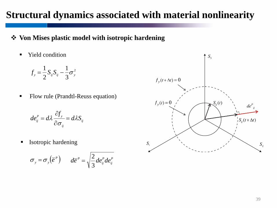
39
Von Mises plastic model with isotropic hardening
Yield condition
Flow rule (Prandtl-Reuss equation)
Isotropic hardening
2
31
21
yijijy SSf σ−=
ijij
yPij Sd
fdde λ
σλ =∂∂
=
( )Pyy eσσ = P
ijPij
P dedeed32
=

Hydrodynamics in the time domain
40
Governing equations
on
Initial conditions at time
for
onfor
0);(2 =∇ txφ in SV
on FS03
=∂∂
+x
g φφ for 03 =x
0 3
=∂∂xφ
on GS
0→∇φ on )( ∞→∞ RS
iinun
=∂∂φ
on BS
( ) 0; =txφ
( ) 0; =txφ
3x
3x
FS
FS
0=t
Hydrodynamics in the time domain
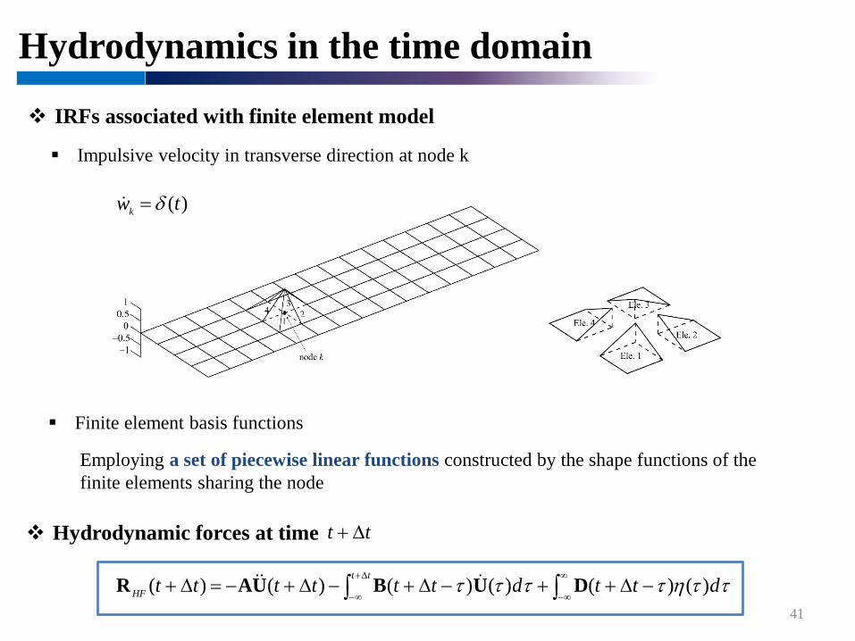
41
IRFs associated with finite element model
)(twk δ=
Hydrodynamic forces at time
∫∫∞
∞−
∆+
∞−−∆++−∆+−∆+−=∆+ ττηττττ dttdtttttt
tt
HF )()()()()()( DUBUAR
Impulsive velocity in transverse direction at node k
tt ∆+
Finite element basis functions
Employing a set of piecewise linear functions constructed by the shape functions of the finite elements sharing the node
Floating plate structure – wave interactions
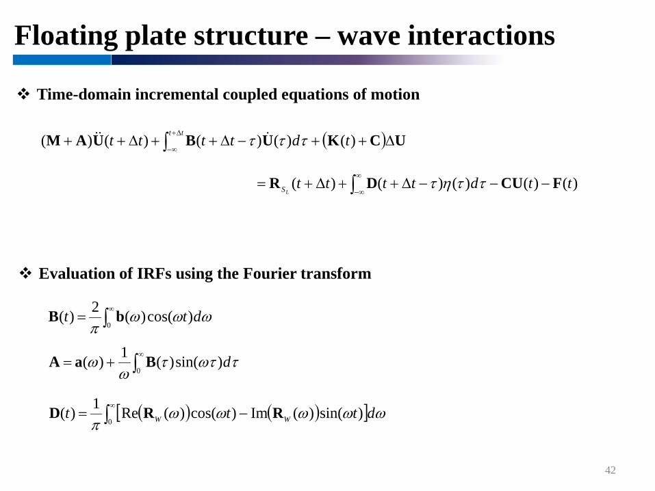
42
Time-domain incremental coupled equations of motion
Evaluation of IRFs using the Fourier transform
( ) UCKUBUAM ∆++−∆++∆++ ∫∆+
∞−)()()()()( tdtttt
ttτττ
)()()()()( ttdttttLS FCUDR −−−∆++∆+= ∫
∞
∞−ττητ
∫∞
=0
)cos()(2)( ωωωπ
dtt bB
∫∞
+=0
)sin()(1)( τωττω
ω dBaA
( ) ( )[ ]∫∞
−=0
)sin()(Im)cos()(Re1)( ωωωωωπ
dttt WW RRD
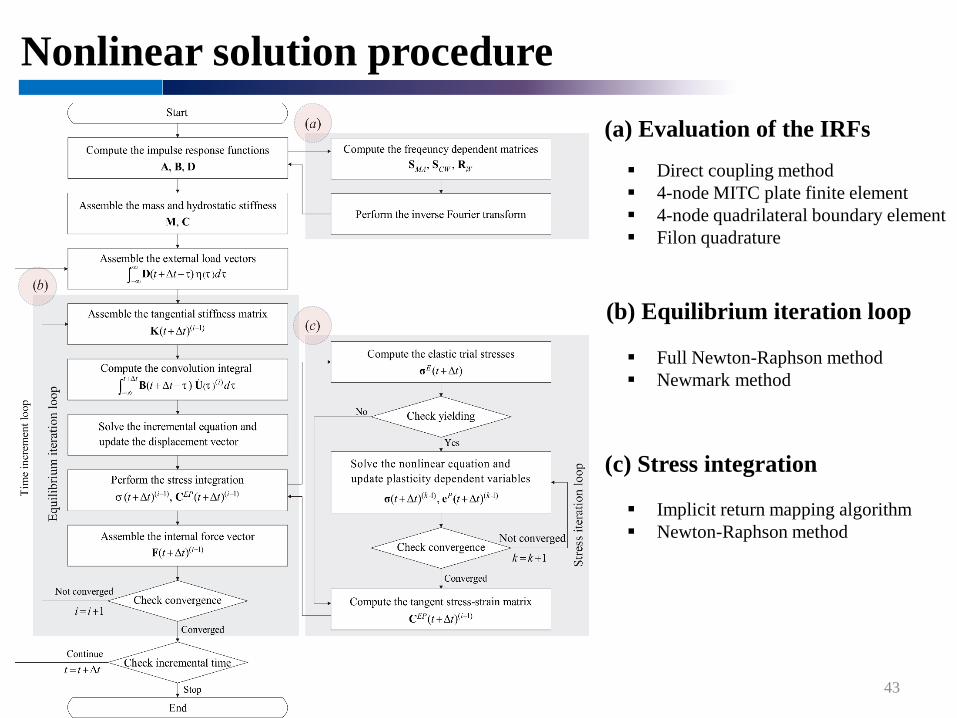
Nonlinear solution procedure
43
(a) Evaluation of the IRFs
(b) Equilibrium iteration loop
(c) Stress integration
Direct coupling method 4-node MITC plate finite element 4-node quadrilateral boundary element Filon quadrature
Implicit return mapping algorithm Newton-Raphson method
Full Newton-Raphson method Newmark method
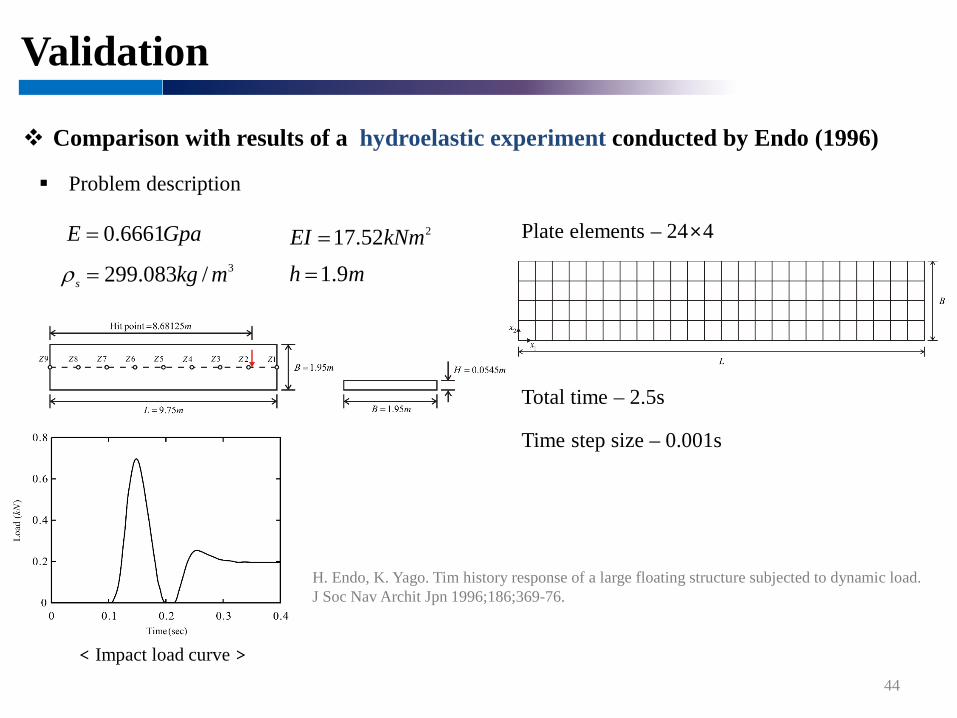
Validation
Comparison with results of a hydroelastic experiment conducted by Endo (1996)
Problem description
H. Endo, K. Yago. Tim history response of a large floating structure subjected to dynamic load. J Soc Nav Archit Jpn 1996;186;369-76.
44
Plate elements – 24×4
Time step size – 0.001s
Total time – 2.5s
< Impact load curve >
GpaE 6661.0= 252.17 kNmEI =3/083.299 mkgs =ρ mh 9.1=

Validation
Numerical modeling in LS-DYNA
45
Air
Water
Floating plate structure
Dimension – 9.75×1.95×0.545
Fluid modeling by MMALE(Multi-Material Arbitrary Lagrangian Eulerian)
FSI modeled by “Constrained Lagrange in Solid”
Dimension – 48.75×9.75×0.95
Air
3D solid elements – 480×80×24
Water
Dimension – 48.75×9.75×1.9
3D solid elements – 480×80×48
Computing coupling forces by a penalty method
Shell elements – 48×8
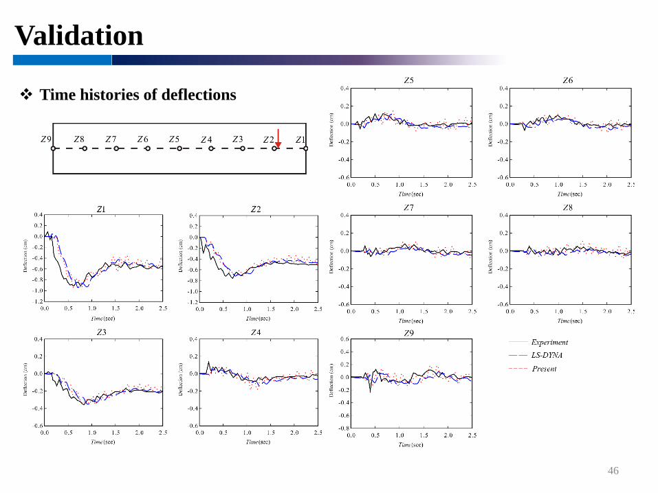
Validation
46
Time histories of deflections
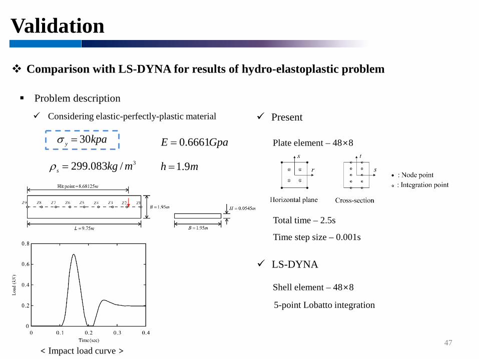
Validation
Comparison with LS-DYNA for results of hydro-elastoplastic problem
Problem description
47
Present
LS-DYNA
Considering elastic-perfectly-plastic material
Time step size – 0.001s
Total time – 2.5s
5-point Lobatto integration
Plate element – 48×8
Shell element – 48×8
< Impact load curve >
GpaE 6661.0=kpay 30=σ
3/083.299 mkgs =ρ mh 9.1=
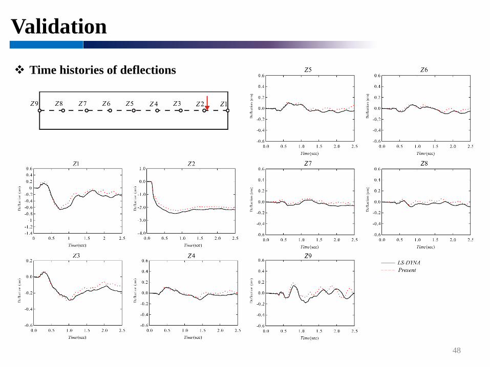
Validation
48
Time histories of deflections
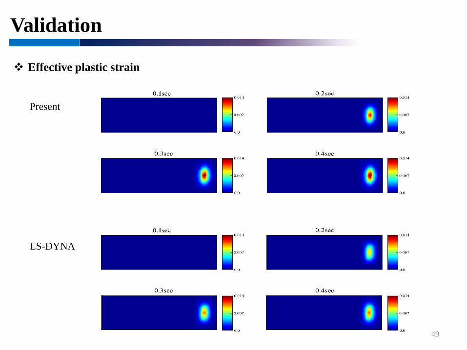
Validation
49
Present
LS-DYNA
Effective plastic strain
Validation
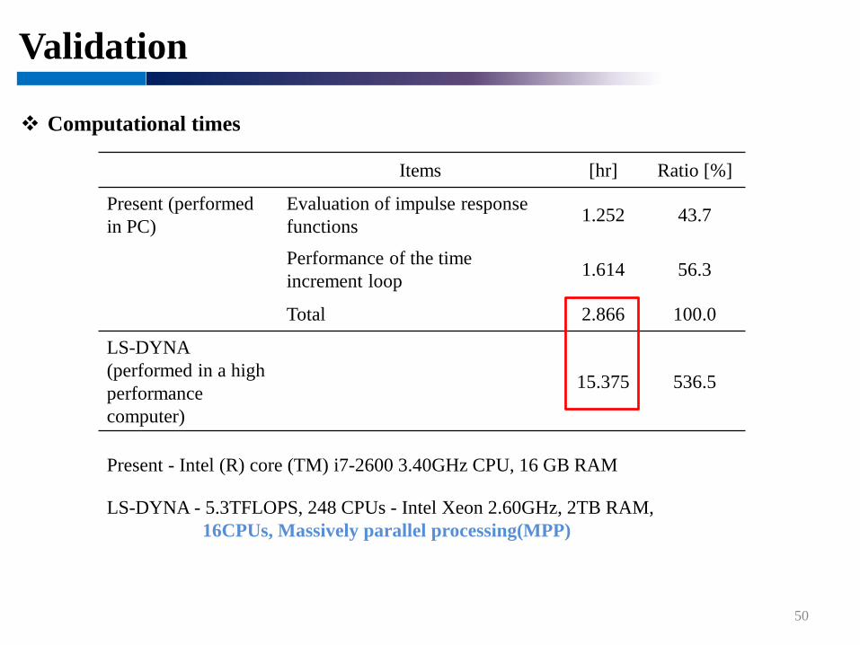
Computational times
50
Present - Intel (R) core (TM) i7-2600 3.40GHz CPU, 16 GB RAM
LS-DYNA - 5.3TFLOPS, 248 CPUs - Intel Xeon 2.60GHz, 2TB RAM, 16CPUs, Massively parallel processing(MPP)
Items [hr] Ratio [%]
Present (performed in PC)
Evaluation of impulse response functions 1.252 43.7
Performance of the time increment loop 1.614 56.3
Total 2.866 100.0
LS-DYNA(performed in a high performance computer)
15.375 536.5
Numerical examples
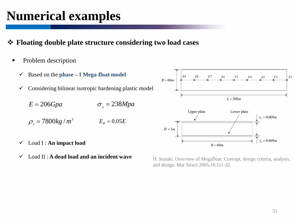
Floating double plate structure considering two load cases
Problem description
H. Suzuki. Overview of Megafloat: Concept, design criteria, analysis, and design. Mar Struct 2005;18;111-32.
51
Based on the phase – I Mega-float model
Considering bilinear isotropic hardening plastic model
Load I : An impact load
Load II : A dead load and an incident wave
GpaE 206=
EEP 05.0=3/7800 mkgs =ρ
Mpay 238=σ
Numerical examples
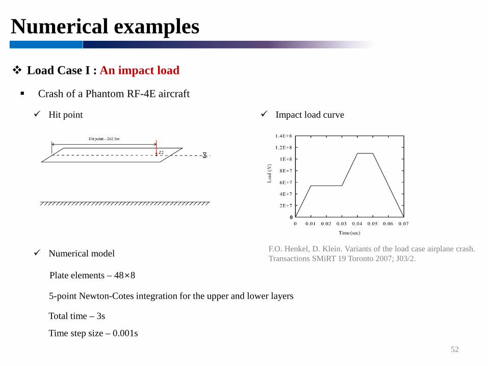
Load Case I : An impact load
Crash of a Phantom RF-4E aircraft
52
Impact load curve Hit point
Time step size – 0.001s
Total time – 3s
Plate elements – 48×8
Numerical model
5-point Newton-Cotes integration for the upper and lower layers
F.O. Henkel, D. Klein. Variants of the load case airplane crash.Transactions SMiRT 19 Toronto 2007; J03/2.

Numerical examples
53
Time histories of deflections

Numerical examples
54
Effective plastic strain
Numerical examples
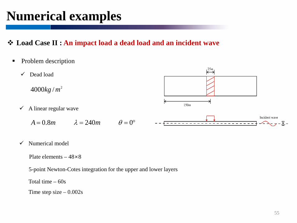
Load Case II : An impact load a dead load and an incident wave
Problem description
55
A linear regular wave
Dead load
Time step size – 0.002s
Total time – 60s
Plate elements – 48×8
Numerical model
5-point Newton-Cotes integration for the upper and lower layers
2/4000 mkg
mA 8.0= m240=λ °= 0θ

Numerical examples
Time histories of deflections
56

Numerical examples
Effective plastic strain
57

58
Conclusion & Future works

Conclusion
59
1. A numerical procedure for a hydroelastic analysis of floating platestructure with multiple hinge connections is proposed
2. We investigated the effect of the number of hinge connections on themaximum bending moment and deflection in floating plate structures.
3. We developed a nonlinear procedure for a hydro-elastoplastic analysisconsidering elastoplastic behaviors and linear waves
4. The hydro-elastoplastic problems of floating plate structures subjected toan impact load or an incident wave under a dead load are solved
Future works
60
Experimental studies for verification of the proposed procedure and
understanding of hydro-elastoplastic behaviors of floating plate structures
Improvement of the proposed method
Computation efficiency through modal analysis or modification of the convolutions
Hydro-elastoplastic analysis of 3D ships or offshore platforms
Nonlinear behaviors of structure and fluid
Experimental set-up
Dimensional analysis

61
Thank you


