24
GRUNDFOS DATA BOOKLET Hydro Solo-E Complete pressure boosting systems 50/60 Hz Lenntech i[email protected] www.lenntech.com

www.lenntech.com - +31(0)[email protected] - +31(0)152-616-2892
Contents
Product dataPerformance range 3Hydro Solo-E 4Operating conditions 4Inlet pressure 4Type key 4Product range 5Construction 5Installation 5Mechanical installation 6Diaphragm tank 6Curve conditions 6Electrical connection 6
Control of CRE pumpsControl options of CRE pumps 7Central management system 7Remote control 7Control panel 7Overview of functions 8
Electrical installationAdditional protection 9Wiring diagram, single-phase 9Wiring diagram, three-phase 1.5 - 7.5 kW 9
Technical dataHydro Solo-E, CRE 1-xx 10Hydro Solo-E, CRE 3-xx 11Hydro Solo-E, CRE 5-xx 12Hydro solo-E, CRE 10-xx 13Hydro Solo-E, CRE 15-xx 14Hydro Solo-E, CRE 20-xx 15Hydro Solo-E, CRE 32-xx 16Hydro Solo-E, CRE 45-xx 17
AccessoriesR100 18Dry-running protection 18
Further product documentationWinCAPS 19WebCAPS 20

www.lenntech.com - +31(0)[email protected] - +31(0)152-616-289
Hydro Solo-E
Product dataPerformance range
TM0
2 75
77 3
8031 2 3 4 6 8 1010 20 30 40 60
Q [m³/h]
20
30
40
50
60
70
80
90
100
H[m]
Hydro Solo-E50 Hz
ISO 9906 Annex A
CRE 45
CRE 32
CRE 20
CRE 15
CRE 10
CRE 5
CRE 3
CRE 1
3
4
Product data
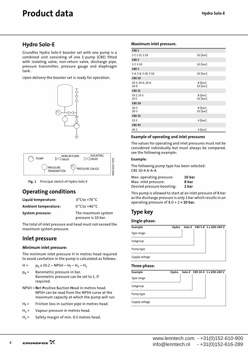
Hydro Solo-EHydro Solo-EGrundfos Hydro Solo-E booster set with one pump is acombined unit consisting of one E-pump (CRE) fittedwith isolating valve, non-return valve, discharge pipe,pressure transmitter, pressure gauge and diaphragmtank.
Upon delivery the booster set is ready for operation.
Fig. 1 Principal sketch of Hydro Solo-E
Operating conditionsLiquid temperature: 0°C to +70 °C
Ambient temperature: 0 °C to +40 °C
System pressure: The maximum system pressure is 10 bar.
The total of inlet pressure and head must not exceed themaximum system pressure.
Inlet pressure
Minimum inlet pressure:
The minimum inlet pressure H in metres head requiredto avoid cavitation in the pump is calculated as follows:
H = pb x 10.2 – NPSH – Hf – Hv – Hs
pb = Barometric pressure in bar.Barometric pressure can be set to 1, if required.
NPSH = Net Positive Suction Head in metres head.NPSH can be read from the NPSH curve at the maximum capacity at which the pump will run.
Hf = Friction loss in suction pipe in metres head.
Hv = Vapour pressure in metres head.
Hs = Safety margin of min. 0.5 metres head.
Maximum inlet pressure.
Example of operating and inlet pressures
The values for operating and inlet pressures must not beconsidered individually but must always be compared,see the following example:
Example:
The following pump type has been selected:CRE 10-4 A-A-A
Max. operating pressure: 10 barMax. inlet pressure: 8 barDesired pressure boosting: 2 bar
This pump is allowed to start at an inlet pressure of 8 baras the discharge pressure is only 2 bar which results in anoperating pressure of 8.0 + 2 = 10 bar.
Type key
Single-phase:
Three-phase:
TM0
0 8
427
270
9VALVE
PRESSURE GAUGE
NON-RETURN
VALVE
ISOLATINGPUMP
PRESSURETRANSMITTER
PUMP
PRESSURETRANSMITTER
NON-RETURNVALVE
ISOLATINGVALVE
PRESSURE GAUGE
CRE 1
1-7, 1-15, 1-19 10 [bar]
CRE 3
3-7, 3-10 10 [bar]
CRE 5
5-4, 5-8, 5-10, 5-16 10 [bar]
CRE 10
10-3, 10-4, 10-610-9
8 [bar]10 [bar]
CRE 15
15-2, 15-315-5
8 [bar]10 [bar]
CRE 20
20-320-5
8 [bar]10 [bar]
CRE 32
32-3 4 [bar]
CRE 45
45-2 4 [bar]
Example Hydro Solo-E CRE 5-8 1 x 200-240 V
Type range
Subgroup
Pump type
Supply voltage
Example Hydro Solo-E CRE 10-4 1 x 200-240 V
Type range
Subgroup
Pump type
Supply voltage
www.lenntech.com - +31(0)[email protected] - +31(0)152-616-289
www.leinfo@le
Product data
nntech.com - +31(0)152-610-900nntech.nl - +31(0)152-616-289
Hydro Solo-E
Product range
Construction
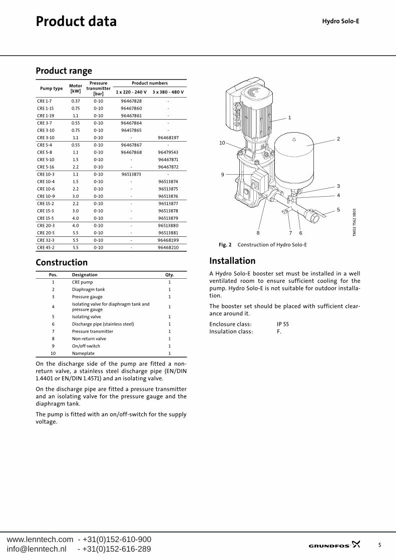
On the discharge side of the pump are fitted a non-return valve, a stainless steel discharge pipe (EN/DIN1.4401 or EN/DIN 1.4571) and an isolating valve.
On the discharge pipe are fitted a pressure transmitterand an isolating valve for the pressure gauge and thediaphragm tank.
The pump is fitted with an on/off-switch for the supplyvoltage.
Fig. 2 Construction of Hydro Solo-E
InstallationA Hydro Solo-E booster set must be installed in a wellventilated room to ensure sufficient cooling for thepump. Hydro Solo-E is not suitable for outdoor installa-tion.
The booster set should be placed with sufficient clear-ance around it.
Enclosure class: IP 55Insulation class: F.
Pump typeMotor[kW]
Pressuretransmitter
[bar]
Product numbers
1 x 220 - 240 V 3 x 380 - 480 V
CRE 1-7 0.37 0-10 96467828 -
CRE 1-15 0.75 0-10 96467860 -
CRE 1-19 1.1 0-10 96467861 -
CRE 3-7 0.55 0-10 96467864 -
CRE 3-10 0.75 0-10 96457865 -
CRE 3-10 1.1 0-10 - 96468197
CRE 5-4 0.55 0-10 96467867 -
CRE 5-8 1.1 0-10 96467868 96479543
CRE 5-10 1.5 0-10 - 96467871
CRE 5-16 2.2 0-10 - 96467872
CRE 10-3 1.1 0-10 96513873 -
CRE 10-4 1.5 0-10 - 96513874
CRE 10-6 2.2 0-10 - 96513875
CRE 10-9 3.0 0-10 - 96513876
CRE 15-2 2.2 0-10 - 96513877
CRE 15-3 3.0 0-10 - 96513878
CRE 15-5 4.0 0-10 - 96513879
CRE 20-3 4.0 0-10 - 96513880
CRE 20-5 5.5 0-10 - 96513881
CRE 32-3 5.5 0-10 - 96468199
CRE 45-2 5.5 0-10 - 96468210
Pos. Designation Qty.
1 CRE pump 1
2 Diaphragm tank 1
3 Pressure gauge 1
4Isolating valve for diaphragm tank and pressure gauge
1
5 Isolating valve 1
6 Discharge pipe (stainless steel) 1
7 Pressure transmitter 1
8 Non-return valve 1
9 On/off-switch 1
10 Nameplate 1TM
02
756
2 38
03
2
3
4
5
67
10
9
8
1
5
6
Product data
Hydro Solo-EMechanical installationThe pipes connected to the booster set must be ofadequate size. To avoid resonance, expansion jointsshould be fitted both in the discharge and suction pipes.
The pipes are to be connected to the discharge pipe andthe pump suction port.
The booster set should be tightened up prior to start-up.
It is always advisable to fit pipe hangers both on thesuction and discharge side.
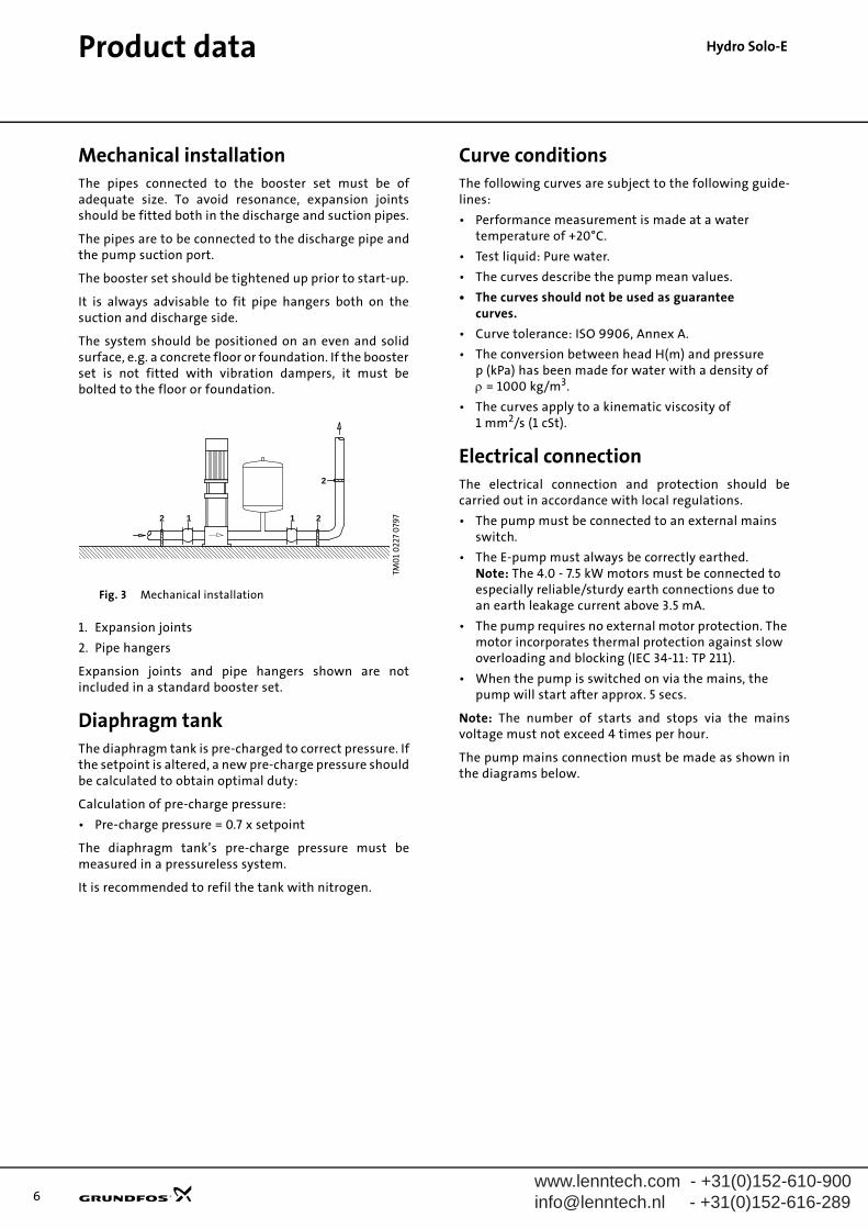
The system should be positioned on an even and solidsurface, e.g. a concrete floor or foundation. If the boosterset is not fitted with vibration dampers, it must bebolted to the floor or foundation.
Fig. 3 Mechanical installation
1. Expansion joints
2. Pipe hangers
Expansion joints and pipe hangers shown are notincluded in a standard booster set.
Diaphragm tankThe diaphragm tank is pre-charged to correct pressure. Ifthe setpoint is altered, a new pre-charge pressure shouldbe calculated to obtain optimal duty:
Calculation of pre-charge pressure:
• Pre-charge pressure = 0.7 x setpoint
The diaphragm tank’s pre-charge pressure must bemeasured in a pressureless system.
It is recommended to refil the tank with nitrogen.
Curve conditionsThe following curves are subject to the following guide-lines:
• Performance measurement is made at a water temperature of +20°C.
• Test liquid: Pure water.
• The curves describe the pump mean values.
• The curves should not be used as guarantee curves.
• Curve tolerance: ISO 9906, Annex A.
• The conversion between head H(m) and pressure p (kPa) has been made for water with a density ofρ = 1000 kg/m3.
• The curves apply to a kinematic viscosity of1 mm2/s (1 cSt).
Electrical connectionThe electrical connection and protection should becarried out in accordance with local regulations.
• The pump must be connected to an external mains switch.
• The E-pump must always be correctly earthed.Note: The 4.0 - 7.5 kW motors must be connected to especially reliable/sturdy earth connections due to an earth leakage current above 3.5 mA.
• The pump requires no external motor protection. The motor incorporates thermal protection against slow overloading and blocking (IEC 34-11: TP 211).
• When the pump is switched on via the mains, the pump will start after approx. 5 secs.
Note: The number of starts and stops via the mainsvoltage must not exceed 4 times per hour.
The pump mains connection must be made as shown inthe diagrams below.
TM0
1 0
227
079
7
2
2 1 1 2
www.lenntech.com - +31(0)[email protected] - +31(0)152-616-289

www.lenntech.com - +31(0)[email protected] - +31(0)152-616-289
Hydro Solo-E
Control of CRE pumpsControl options of CRE pumpsCommunication with CRE pumps is possible by means of
• a central management system,
• remote control (Grundfos R100) or
• a control panel.
The purpose of controlling an E-pump is to monitor andcontrol the pressure, temperature, flow and liquid levelof the system.
Central management system
Communication with the CRE pump is possible eventhough the operator is not present near the CRE pump.
Communication is enabled by having connected the CREpump to a central management system allowing theoperator to monitor and change control modes andsetpoint settings of the CRE pump.
Fig. 4 Structure of a central management system
Remote control
The R100 remote control produced by Grundfos is avail-able as an accessory.
The operator communicates with the CRE pump bypointing the IR-signal transmitter at the control panel ofthe E-pump terminal box.
Fig. 5 R100 remote control
On the R100 display it is possible to monitor and changecontrol modes and settings of the CRE pump.
Control panel
The control panel of the CRE pump terminal box makesit possible to change the setpoint settings manually.
Fig. 6 Control panel on CRE pump
TM0
659
2 11
03
LON-bus connection
GENIbus connection
G10-LONInterface
CRE pump
TM0
0 4
498
280
2TM
00
76
00
040
4
Light fields
Buttons
Indicator lights
7

8
Control of CRE pumps
Hydro Solo-EOverview of functionsE-pumps/functions Hydro Solo-E
TM0
0 7
60
0 0
404
Setting via control panel:
Setpoint
Start/stop
Max. curve
Min. curve
Reading via control panel:
Setpoint
Operating indication
Fault indicationTM
00
449
8 28
02
Setting via R100:
Setpoint
Start/stop
Max. curve
Min. curve
Controlled/uncontrolled
PI-controller
Signal relay
Operating range
Stop function
Reading via R100:
Setpoint
Operating indication
Pump status
www.lenntech.com - +31(0)[email protected] - +31(0)152-616-289
www.lenntech.com - +31(0)[email protected] - +31(0)152-616-289 9
Hydro Solo-EElectrical installation
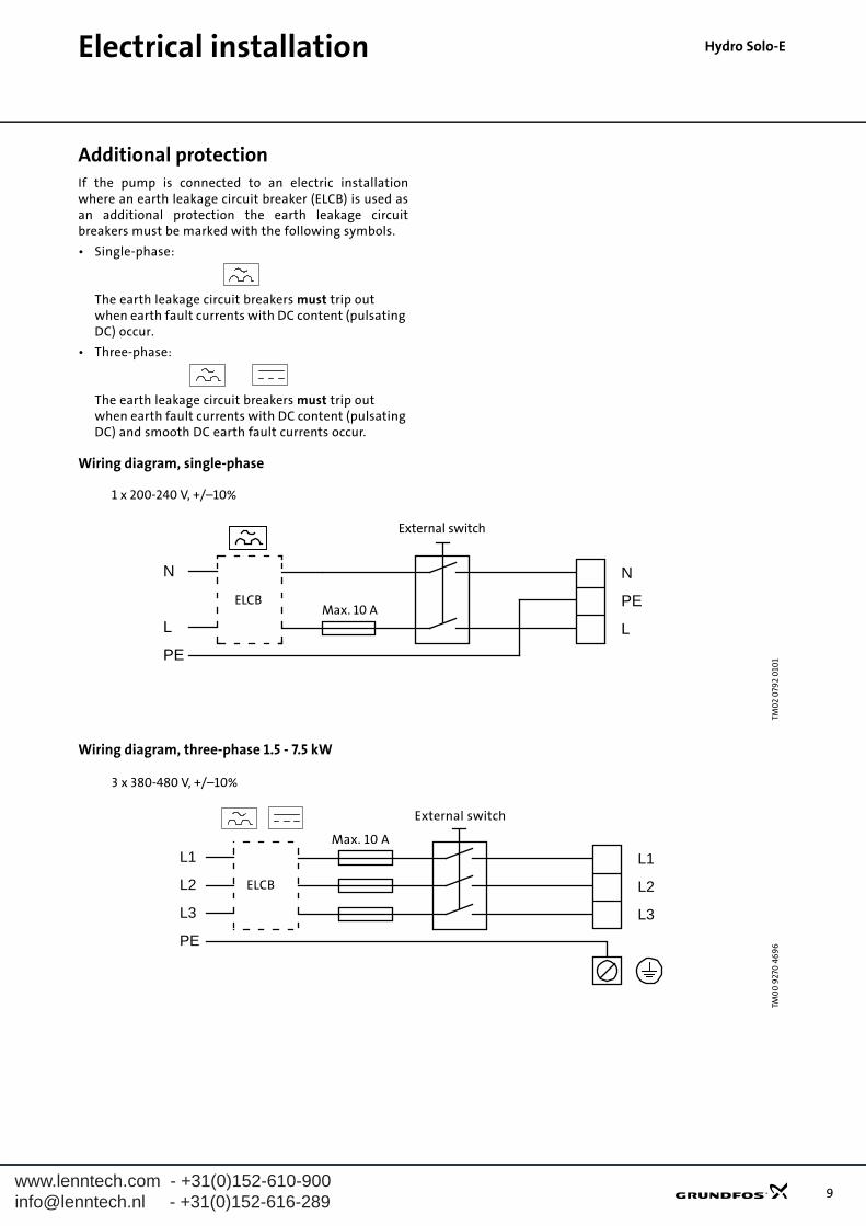
Additional protectionIf the pump is connected to an electric installationwhere an earth leakage circuit breaker (ELCB) is used asan additional protection the earth leakage circuitbreakers must be marked with the following symbols.
• Single-phase:
The earth leakage circuit breakers must trip out when earth fault currents with DC content (pulsating DC) occur.
• Three-phase:
The earth leakage circuit breakers must trip out when earth fault currents with DC content (pulsating DC) and smooth DC earth fault currents occur.
Wiring diagram, single-phase
Wiring diagram, three-phase 1.5 - 7.5 kW
TM0
2 0
792
010
1
N
PE
L
N
L
PE
ELCB
1 x 200-240 V, +/–10%
Max. 10 A
External switch
TM0
0 9
270
46
96
L1
L2
L3
L2
L1
L3
PE
3 x 380-480 V, +/–10%
External switch
Max. 10 A
ELCB
10
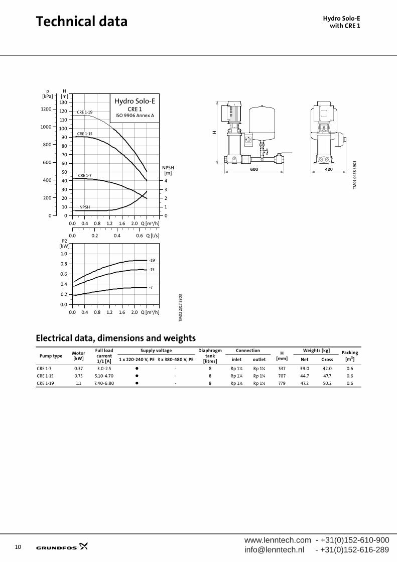
Hydro Solo-Ewith CRE 1
Technical dataElectrical data, dimensions and weights
TM0
2 23
17 3
803H
ydro
So
lo-E
, CR
E 1-
xx
0.0 0.4 0.8 1.2 1.6 2.0 Q [m³/h]
0
10
20
30
40
50
60
70
80
90
100
110
120
130
H[m]
0.0 0.2 0.4 0.6 Q [l/s]
0
200
400
600
800
1000
1200
p[kPa]
0
1
2
3
4
NPSH[m]
Hydro Solo-ECRE 1
ISO 9906 Annex ACRE 1-19
CRE 1-15
CRE 1-7
NPSH
0.0 0.4 0.8 1.2 1.6 2.0 Q [m³/h]
0.0
0.2
0.4
0.6
0.8
1.0
P2[kW]
-19
-15
-7
TM0
1 0
458
390
3
600 420
H
Pump typeMotor[kW]
Full loadcurrent1/1 [A]
Supply voltage Diaphragm tank
[litres]
ConnectionH
[mm]
Weights [kg] Packing
[m3]1 x 220-240 V, PE 3 x 380-480 V, PE inlet outlet Net Gross
CRE 1-7 0.37 3.0-2.5 - 8 Rp 1¼ Rp 1¼ 537 39.0 42.0 0.6
CRE 1-15 0.75 5.10-4.70 - 8 Rp 1¼ Rp 1¼ 707 44.7 47.7 0.6
CRE 1-19 1.1 7.40-6.80 - 8 Rp 1¼ Rp 1¼ 779 47.2 50.2 0.6
www.lenntech.com - +31(0)[email protected] - +31(0)152-616-289
www.leinfo@le
Technical data
nntech.com - +31(0)152-610-900nntech.nl - +31(0)152-616-289
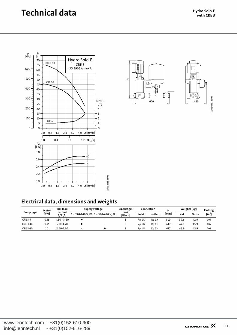
Hydro Solo-Ewith CRE 3
Electrical data, dimensions and weights
TM0
2 23
18 3
803H
ydro
So
lo-E
, CR
E 3-
xx
0.0 0.8 1.6 2.4 3.2 4.0 Q [m³/h]
0
5
10
15
20
25
30
35
40
45
50
55
60
65
70
H[m]
0.0 0.4 0.8 1.2 Q [l/s]
0
100
200
300
400
500
600
p[kPa]
0
1
2
3
4
NPSH[m]
Hydro Solo-ECRE 3
ISO 9906 Annex A
CRE 3-10
CRE 3-7
NPSH
0.0 0.8 1.6 2.4 3.2 4.0 Q [m³/h]
0.0
0.2
0.4
0.6
0.8
P2[kW]
-10
-7
TM0
1 0
457
390
3
600 420
H
Pump typeMotor[kW]
Full loadcurrent1/1 [A]
Supply voltage Diaphragm tank
[litres]
ConnectionH
[mm]
Weights [kg] Packing
[m3]1 x 220-240 V, PE 3 x 380-480 V, PE inlet outlet Net Gross
CRE 3-7 0.55 4.30 - 3.60 - 8 Rp 1¼ Rp 1¼ 519 39.6 42.9 0.6
CRE 3-10 0.75 5.10-4.70 - 8 Rp 1¼ Rp 1¼ 617 42.9 45.9 0.6
CRE 3-10 1.1 2.60-2.30 - 8 Rp 1¼ Rp 1¼ 617 42.9 45.9 0.6
11
12
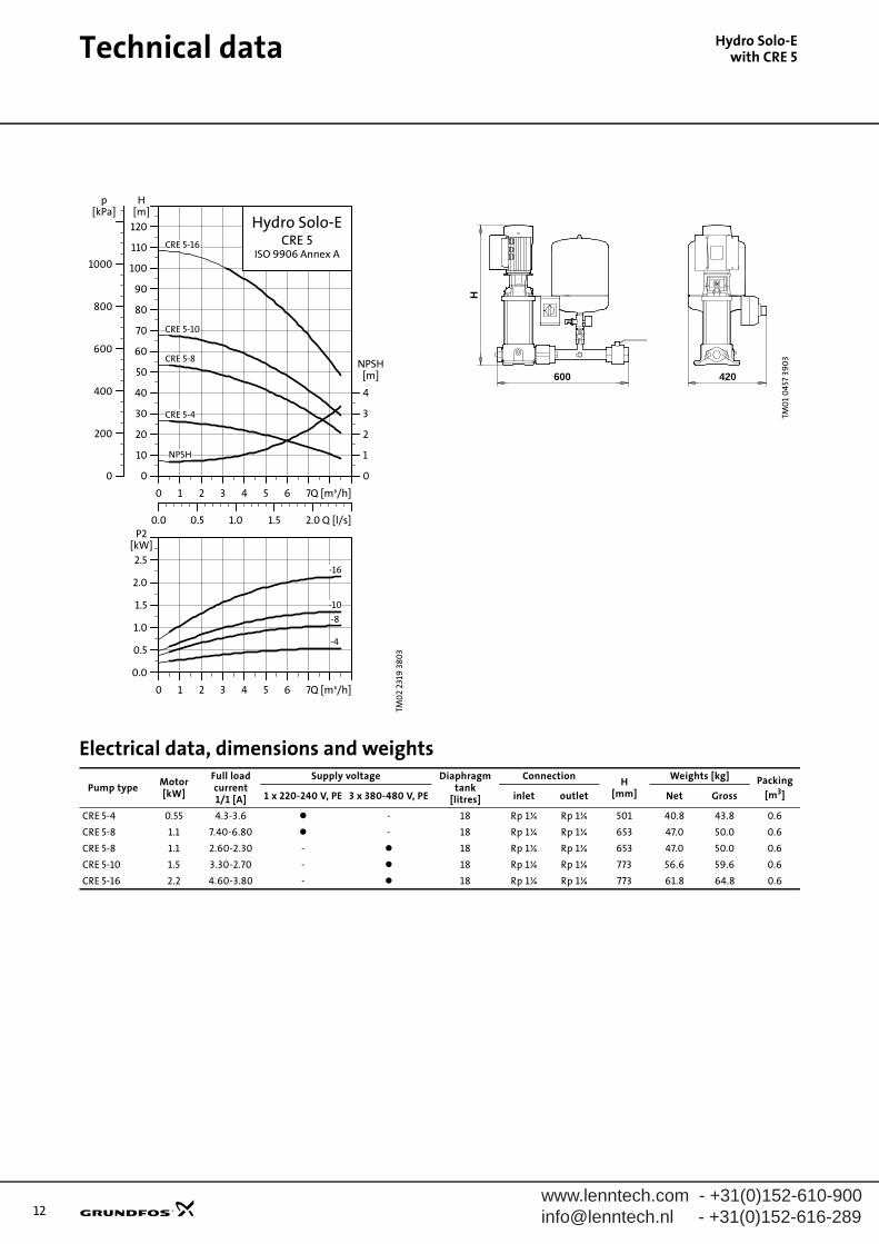
Technical data
Hydro Solo-Ewith CRE 5Electrical data, dimensions and weights
TM0
2 23
19 3
803H
ydro
So
lo-E
, CR
E 5-
xx
0 1 2 3 4 5 6 7Q [m³/h]
0
10
20
30
40
50
60
70
80
90
100
110
120
H[m]
0.0 0.5 1.0 1.5 2.0 Q [l/s]
0
200
400
600
800
1000
p[kPa]
0
1
2
3
4
NPSH[m]
Hydro Solo-ECRE 5
ISO 9906 Annex A
CRE 5-10
CRE 5-16
CRE 5-4
CRE 5-8
NPSH
0 1 2 3 4 5 6 7Q [m³/h]
0.0
0.5
1.0
1.5
2.0
2.5
P2[kW]
-16
-10
-8
-4
TM0
1 0
457
390
3
600 420
H
Pump typeMotor[kW]
Full loadcurrent1/1 [A]
Supply voltage Diaphragm tank
[litres]
ConnectionH
[mm]
Weights [kg] Packing
[m3]1 x 220-240 V, PE 3 x 380-480 V, PE inlet outlet Net Gross
CRE 5-4 0.55 4.3-3.6 - 18 Rp 1¼ Rp 1¼ 501 40.8 43.8 0.6
CRE 5-8 1.1 7.40-6.80 - 18 Rp 1¼ Rp 1¼ 653 47.0 50.0 0.6
CRE 5-8 1.1 2.60-2.30 - 18 Rp 1¼ Rp 1¼ 653 47.0 50.0 0.6
CRE 5-10 1.5 3.30-2.70 - 18 Rp 1¼ Rp 1¼ 773 56.6 59.6 0.6
CRE 5-16 2.2 4.60-3.80 - 18 Rp 1¼ Rp 1¼ 773 61.8 64.8 0.6
www.lenntech.com - +31(0)[email protected] - +31(0)152-616-289

www.leinfo@le
Technical data
nntech.com - +31(0)152-610-900nntech.nl - +31(0)152-616-289
Hydro Solo-Ewith CRE 10
Electrical data, dimensions and weights
TM0
2 75
34 3
803H
ydro
so
lo-E
, CR
E 10
-xx
0 2 4 6 8 10 Q [m³/h]
0
10
20
30
40
50
60
70
80
90
100
110
120
H[m]
0.0 0.5 1.0 1.5 2.0 2.5 3.0 Q [l/s]
0
200
400
600
800
1000
p[kPa]
0
1
2
3
4
NPSH[m]
Hydro Solo-ECRE 10
ISO 9906 Annex A
NPSH
CRE 10-9
CRE 10-6
CRE 10-4
CRE 10-3
0 2 4 6 8 10 Q [m³/h]
0.0
0.5
1.0
1.5
2.0
2.5
3.0
P2[kW]
-9
-6
-4
-3
TM0
2 75
63
380
3
650 425
H
Pump typeMotor[kW]
Full loadcurrent1/1 [A]
Supply voltage Diaphragm tank
[litres]
ConnectionH
[mm]
Weights [kg] Packing
[m3]1 x 220-240 V, PE 3 x 380-480 V, PE inlet outlet Net Gross
CRE 10-3 1.1 7.40-6.80 - 33 Rp 1½ Rp 1½ 608 62.0 65.0 0.6
CRE 10-4 1.5 3.30-2.70 - 33 Rp 1½ Rp 1½ 704 71.0 74.0 0.6
CRE 10-6 2.2 4.60-3.80 - 33 Rp 1½ Rp 1½ 804 80.0 83.0 0.6
CRE 10-9 3.0 6.40-5.20 - 33 Rp 1½ Rp 1½ 913 87.0 90.0 0.6
13
14
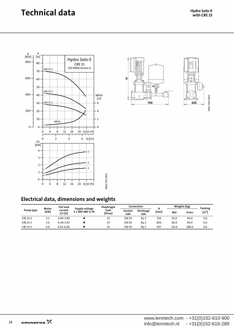
Technical data
Hydro Solo-Ewith CRE 15Electrical data, dimensions and weights
TM0
2 75
35 3
803H
ydro
So
lo-E
, CR
E 15
-xx
0 4 8 12 16 20 Q [m³/h]
0
10
20
30
40
50
60
70
80
H[m]
0 2 4 6 Q [l/s]
0
200
400
600
800
p[kPa]
0
2
4
6
NPSH[m]
Hydro Solo-ECRE 15
ISO 9906 Annex A
NPSH
CRE 15-5
CRE 15-3
CRE 15-2
0 4 8 12 16 20 Q [m³/h]
0
1
2
3
4
P2[kW]
-5
-3
-2
TM0
2 75
64
380
3
700 425
H
Pump typeMotor[kW]
Full loadcurrent1/1 [A]
Supply voltage3 x 380-480 V, PE
Diaphragm tank
[litres]
ConnectionH
[mm]
Weights [kg]Packing
[m3]Suctionside
Discharge side
Net Gross
CRE 15-2 2.2 4.60-3.80 33 DN 50 Rp 2 736 91.0 94.0 0.6
CRE 15-3 3.0 6.40-5.20 33 DN 50 Rp 2 800 96.0 99.0 0.6
CRE 15-5 4.0 8.10-6.60 33 DN 50 Rp 2 927 115.0 188.0 0.6
www.lenntech.com - +31(0)[email protected] - +31(0)152-616-289

www.leinfo@le
Technical data
nntech.com - +31(0)152-610-900nntech.nl - +31(0)152-616-289
Hydro Solo-Ewith CRE 20
Electrical data, dimensions and weights
TM0
2 75
36 3
803H
ydro
So
lo-E
, CR
E 20
-xx
0 4 8 12 16 20 24 Q [m³/h]
0
10
20
30
40
50
60
70
80
90
H[m]
0 2 4 6 Q [l/s]
0
200
400
600
800
p[kPa]
0
2
4
6
NPSH[m]
Hydro Solo-ECRE 20
ISO 9906 Annex A
NPSH
CRE 20-5
CRE 20-3
0 4 8 12 16 20 24 Q [m³/h]
0
1
2
3
4
5
P2[kW]
-5
-3
TM0
2 75
64
380
3
700 425
H
Pump typeMotor[kW]
Full loadcurrent1/1 [A]
Supply voltage3 x 380-480 V, PE
Diaphragm tank
[litres]
ConnectionH
[mm]
Weights [kg]Packing
[m3]Suctionside
Discharge side
Net Gross
CRE 20-3 4.0 8.10-6.60 33 DN 50 Rp 2 837 112.0 115.0 0.6
CRE 20-5 5.5 11.0-8.80 33 DN 50 Rp 2 978 136.0 133.0 0.6
15
16
Technical data
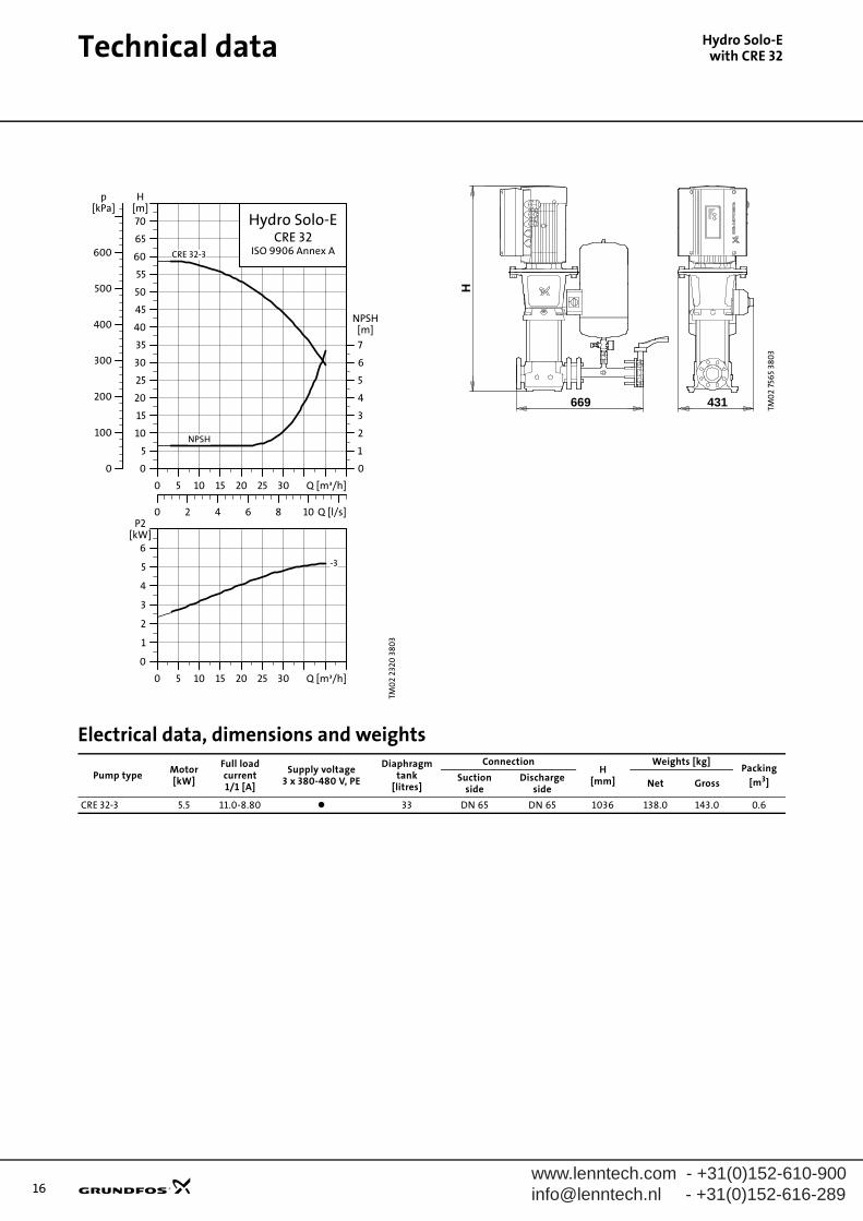
Hydro Solo-Ewith CRE 32Electrical data, dimensions and weights
TM0
2 23
20 3
803H
ydro
So
lo-E
, CR
E 32
-xx
0 5 10 15 20 25 30 Q [m³/h]
0
5
10
15
20
25
30
35
40
45
50
55
60
65
70
H[m]
0 2 4 6 8 10 Q [l/s]
0
100
200
300
400
500
600
p[kPa]
0
1
2
3
4
5
6
7
NPSH[m]
Hydro Solo-ECRE 32
ISO 9906 Annex ACRE 32-3
NPSH
0 5 10 15 20 25 30 Q [m³/h]
0
1
2
3
4
5
6
P2[kW]
-3
TM0
2 75
65
380
3
431
H
669
Pump typeMotor[kW]
Full loadcurrent1/1 [A]
Supply voltage3 x 380-480 V, PE
Diaphragm tank
[litres]
ConnectionH
[mm]
Weights [kg]Packing
[m3]Suctionside
Discharge side
Net Gross
CRE 32-3 5.5 11.0-8.80 33 DN 65 DN 65 1036 138.0 143.0 0.6
www.lenntech.com - +31(0)[email protected] - +31(0)152-616-289
www.leinfo@le
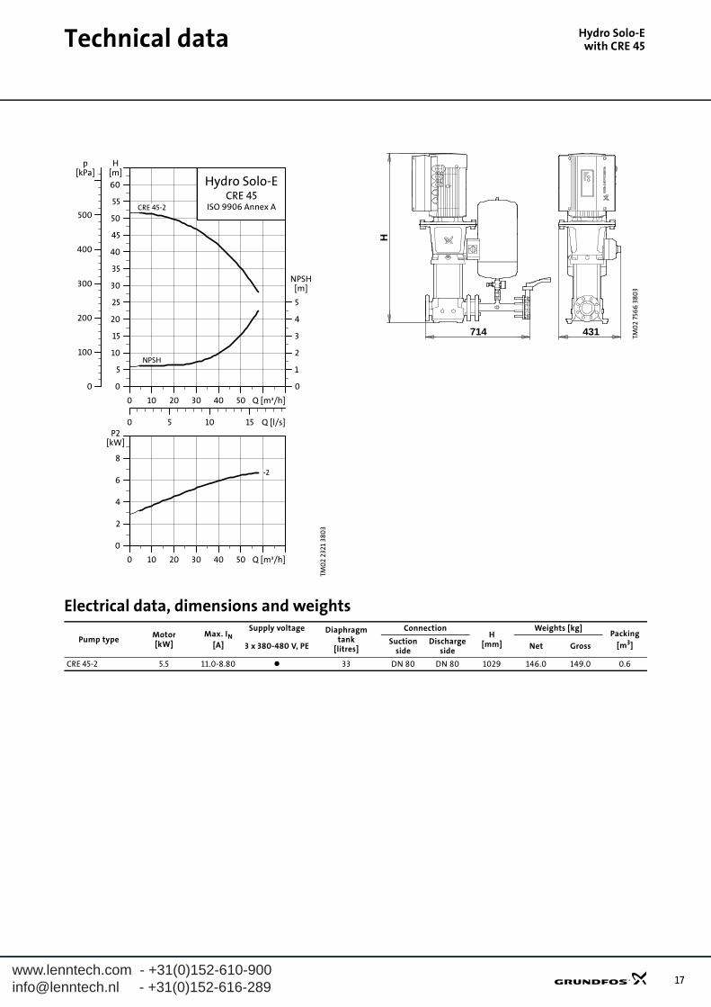
Technical data
nntech.com - +31(0)152-610-900nntech.nl - +31(0)152-616-289
Hydro Solo-Ewith CRE 45
Electrical data, dimensions and weights
TM0
2 23
21 3
803H
ydro
So
lo-E
, CR
E 4
5-xx
0 10 20 30 40 50 Q [m³/h]
0
5
10
15
20
25
30
35
40
45
50
55
60
H[m]
0 5 10 15 Q [l/s]
0
100
200
300
400
500
p[kPa]
0
1
2
3
4
5
NPSH[m]
Hydro Solo-ECRE 45
ISO 9906 Annex A
NPSH
CRE 45-2
0 10 20 30 40 50 Q [m³/h]
0
2
4
6
8
P2[kW]
-2
TM0
2 75
66
380
3
H
431714
Pump typeMotor[kW]
Max. IN[A]
Supply voltage Diaphragm tank
[litres]
ConnectionH
[mm]
Weights [kg]Packing
[m3]3 x 380-480 V, PESuction
sideDischarge
sideNet Gross
CRE 45-2 5.5 11.0-8.80 33 DN 80 DN 80 1029 146.0 149.0 0.6
17
www.lenntech.com - +31(0)[email protected] - +31(0)152-616-28918
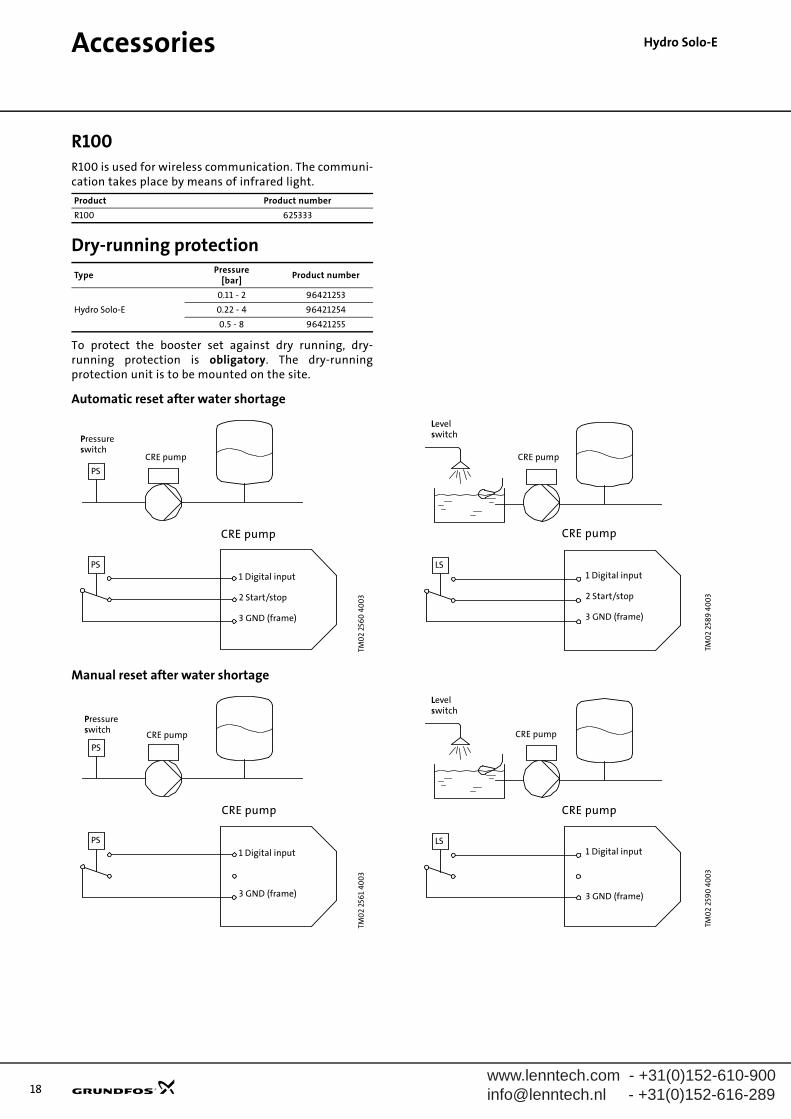
Hydro Solo-EAccessories
R100R100 is used for wireless communication. The communi-cation takes place by means of infrared light.
Dry-running protection
To protect the booster set against dry running, dry-running protection is obligatory. The dry-runningprotection unit is to be mounted on the site.
Automatic reset after water shortage
Manual reset after water shortage
Product Product number
R100 625333
TypePressure
[bar]Product number
Hydro Solo-E
0.11 - 2 96421253
0.22 - 4 96421254
0.5 - 8 96421255
TM0
2 25
60
40
03
TM0
2 25
61
400
3
Pressureswitch
CRE pump
PS
CRE pump
1 Digital input
2 Start/stop
3 GND (frame)
PS
Pressureswitch
PS
CRE pump
1 Digital input
3 GND (frame)
PSCRE pump
TM0
2 25
89 4
00
3TM
02
259
0 4
00
3
Levelswitch
CRE pump
LS
CRE pump
1 Digital input
2 Start/stop
3 GND (frame)
Levelswitch
LS
CRE pump
1 Digital input
3 GND (frame)
CRE pump
www.lenntech.com - +31(0)[email protected] - +31(0)152-616-289
ntation
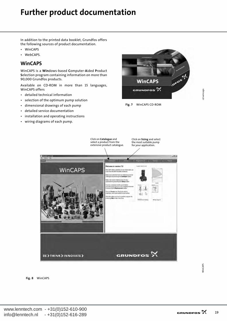
Further product documeIn addition to the printed data booklet, Grundfos offersthe following sources of product documentation.
• WinCAPS
• WebCAPS.
WinCAPSWinCAPS is a Windows-based Computer-Aided ProductSelection program containing information on more than90,000 Grundfos products.
Available on CD-ROM in more than 15 languages,WinCAPS offers
• detailed technical information
• selection of the optimum pump solution
• dimensional drawings of each pump
• detailed service documentation
• installation and operating instructions
• wiring diagrams of each pump.
Fig. 7 WinCAPS CD-ROM
Fig. 8 WinCAPS
cd-w
inca
psW
inC
APS
Click on Catalogue andselect a product from theextensive product catalogue.
Click on Sizing and selectthe most suitable pumpfor your application.
19

20
Further product documentation
WebCAPSWebCAPS is a Web-based Computer Aided-ProductSelection program and a web-version of WinCAPS.
Available on Grundfos’ homepage, www.grundfos.com,WebCAPS offers
• detailed technical information
• dimensional drawings of each pump
• wiring diagrams of each pump.
Fig. 9 WebCAPS
Web
CA
PS
Click Catalogue andselect a product fromthe extensiveproduct catalogue.
Click Replacementand select the rightreplacement pumpbased on thecurrent installation.
Click Productsearch and selecta product from theextensive productcatalogue.
Click Service toto find informationon service kits andspare parts.
Click Units and select yourpreferred units of measurement:- Default units- SI units- US units.
Click Language andselect your preferredlanguage.
Click Literature toselect and downloadGrundfos documentationby browsing the productranges or performinga specific search. Theliterature includes:- Data booklets- Installation and
- Service instructions.operating instructions
If you are a registereduser click Log in to:- save your settings- define and save your
own units- save personalised
information.
Click CAD drawingsto select and downloadCAD darwings in:- .stp- .dxf- .dwg
Click the drop-down list toselect the frequency
www.lenntech.com - +31(0)[email protected] - +31(0)152-616-289

www.leinfo@le
nntech.com - +31(0)152-610-900nntech.nl - +31(0)152-616-289
21
www.leinfo@le
nntech.com - +31(0)152-610-900nntech.nl - +31(0)152-616-289
23
V7140010 0305GBRepl. V7140010 0604
Subject to alterations.
Being responsible is our foundationThinking ahead makes it possible
Innovation is the essence


