107
NGIN RING May 2 14 http hi q.li nde g s . com

7/21/2019 Hydrocarbon Engineering Mayo 2014 Vol 19 05
http://slidepdf.com/reader/full/hydrocarbon-engineering-mayo-2014-vol-19-05 1/107
ROC RBON
NGIN RING
http hiq.linde g s .com

7/21/2019 Hydrocarbon Engineering Mayo 2014 Vol 19 05
http://slidepdf.com/reader/full/hydrocarbon-engineering-mayo-2014-vol-19-05 2/107
-
,....
~
•
,
•
ontents
(03) Comment
(05)
WorLd News
Contract awards. project updates. industry latest, news digest,
diary
dates. mergers and acquisitions
(12) Hydrocarbons in Sub-Saharan Africa
Elizabeth Ste
ph ens,
Jardine Lloyd Thompson, UK,
discusses
risk
and
the protection of
investments in Sub-Saharan Afr ica
(20)
I<eep
up
the
pace
Mark Schott and NeH Eckersley, UOP
LLC.
A Honeywelt
Company, explain
why
rapid project deployment is needed
to ensure
the
oil and gas industry keeps up with shale
product ion levels
(25) (EMS compliance
Eric
WHey and
Hung-Ming
Sung. Trinity Consultants,
USA.
and
Arun Kanchan, Trinity Consultants, Qatar, discuss best practice
in emissions monitoring
(30) Driving refining change: Part two
Stephen Harrison, linde,
USA,
takes a look at how
automotive
emissions legislation and
the
drive
for
energy sustainability
are impacting the refining industry
(37)
Slime control
Taeko Nakamura, Kurita
Water
Industries Ltd., Japan, and Bjorn
Hansen, Kurita Europe GmbH. Germany. discuss slime control
as a biofouling preventative measure
(44) Middle East flaring solution
Clayton
A.
Francis. Zeeco, USA, discusses how high pressure
air assist system flaring technology can resolve the challenges
posed by a
Middle
Eastern environment
(51) A catalyst solution
Patrick Gripka, Opinder Bhan, Wes Whitecotton and James
Esteban. Criterion Catalysts and Technologies, USA, take a
look
at
Tier 3 capital avoidance
with
the help
of
ca
taly
st
solutions
Join
the
. W
conversation. follow
I_._
conned
fm.
like join
--
..,..
(57) Formulation flexibility
Charles Radcliffe. Tom Ventham and
Ra
y Fletcher, Johnson
Matthey
Process Technologies In
c.,
Europe, discuss
continuous catalyst replacement as a means to increased
profitability
(63) Accelerated catalyst evaluation
Florian Huber.
Sven
K. Weber. Jochen Berg. Tilman Sauer and
Alfred Haas, hte GmbH, Germany. and Karl Hutter, Anton
Purgstaller,
OMV
Refining Marketing GmbH, Austria. discuss
how
hydroprocessing full size
commercial
catalyst evaluation
can
be accelerated
for
improved
efficiency
(69) It's electric
Roly Juliano, Watlow, Germany, di
sc
usses the use
of
electric
heaters in refineries and petrochemical plants
(74) Upwards spiral
Stefan Gavelin and Volker Beermann, Tranter GmbH, discuss
how spiral heat exchangers can help to maximise throughput
of
profitable products, and minimise operating expenditures
(81) Beyond basic efficiency
Bart van den Berg. HeatMatrix Group. The Netherlands,
discusses how polymer air preheaters can contribute to
improved energy efficiency
(85) Right temperature
Anton Gurman,
BARTEC
Rus GmbH, Russia , discusses
temperature management in crude
oil
terminals
(87)
Simplicity is key
Chris
Jame
s
SKF
Condition
Monitoring
, Asia Pacific, discusses
advances and challenges
to
wirele
ss condition
monitoring
for
balance of plant equipment
(91) Maintenance review 1
Hydrocarbon ngineering
provides an overvi ew of
maintenance projects undertaken around the wo rld over the
past
12
months
(120) 15 facts on ..
This
month
we give you 15 facts on Sub-Saharan Africa
_.......-UdJllW. ..
...,..._. _d
... FObIOt '
......
._ . .
......... . .._ _
..., '
r . . . _ ~ _ p k o o < _ ~ _
_ 'pno..,...,._d
...
«>Pr 'cN_
...
.....,.--'' ' ' ' ' ' ' ',.,.......
... , _d ... ,.,pocIo..<
'
'''' Oh
......... .....
.--..
.. 'apIooonod .....
_
.....
0 ' ~ . . . d
...._ ,... ......
..,_
..... . . . . . .I<.u-apo;.nocI ~

7/21/2019 Hydrocarbon Engineering Mayo 2014 Vol 19 05
http://slidepdf.com/reader/full/hydrocarbon-engineering-mayo-2014-vol-19-05 3/107

7/21/2019 Hydrocarbon Engineering Mayo 2014 Vol 19 05
http://slidepdf.com/reader/full/hydrocarbon-engineering-mayo-2014-vol-19-05 4/107
omment
I
can't
be
denied that the oil and
gas
industry is male dominated and
casting your eye around any trade
show,
conference or
works
pace
will
confirm
this. Occupations w ithin our industry, and engineering
as a whole, have
always
been considered as male career paths,
however
, is the industry losing out by not tapping
into
a large
portion
of
the talent pool and does more need to
be
done
to
draw
women
to
the sector? Ive
asked
myself these questions frequently
over the last month or so as there
has
been
an influx
of comments and
reports on the oil and
gas
gender gap. female employment and the
gene
ral position
of
women
in
the oil and
gas
industry.
A recent report from
NES
Global Talent
was
initially encouraging
as
it
reported that 75% of women felt welcome working
in
the oil and
gas
industry' and
it
also found that '82 of the respondents planned to
stay
in
the
oil
and
gas
industry
for
the next 2 - 5 years.' The
IHS
report
Minority and
Female
mployment in the Oil Gas an Petrochemical
Industries
stated that 'women will share
in
the growth of more skilled
wh ite collar jobs and more opportunities are likely
to
become
av
ailable
for
female petroleum engineers. managers
et
e. and is expected
to
increase
by
almost 70 000
up
to 2030' a
nd
this wa s
also
heartening
new
s
As
the discussion of the
skills
gap continues,
it
is
great
to
see that
there is enthusiasm and growth potential
for
women to enter and bu i
ld
a career within such a male dominated sector that is in need of support
and
fresh
recruits.
However, there
is still work
to
be
done
if
the oil and
gas
industry
is to att
ra
ct and retain women. The NES report found that almost
half of the female respoodents didn 't believe that they got the same
contact info
Claira LLoyd Editor
recognition
as
male colleagues, also. the
lack
of female mentors
was flagged as
something that the industry needs
to
rectify if it is to guarantee female employee
retention. career development
an
d
confidence.
The IHS
report also pointed
out that there are roles within the industry
that are
known
as
'traditional' female jobs
and t
hey
usually fall in to the O
ffi
ce and Administration Support (OAS)
departments. This can deter women
fr
om explori
ng
other careers
in
the
sector and clearly needs to
be
rectified. Ave r
il
Macdonald.
Professor
of Science
Engagement
, Unive rsity of Reading, UK . said, 'oil
and
gas
sector companies should focus on engaging with young women both
at school and at university,
providing
role models and
an
opportunity
to see
for
themselves what the sector
has to
offer through visits
and
paid internships.'
The female portion of the oil and
gas
industry is
eVidently
strong,
but
sma ll
,
as discuss
ed above and Ido agree with report
findings
that
more needs to
be
done
to
allow t
he
industry
to
bene
fit fr
om the
seas
of
female talent that are
availab
le.
The
next steps to take,
in
my
opinion, reqUire the
issue
of worker equality to be addressed
and
a
stronger leadership and support network needs to be developed within
companies. However, the foundations
to
att
ra
ct female students to
STEM subjects at school and university need to be laid first, so that
these talents are brought into and made available to our
industry
in the
first
place.
MANAGING EDITOR
lames Little
james.little@hydrocarbonengineerin g.com
WEB
MANAGER Tom fullerton
tom.fullerton@hyd rocarbonengineering .
com
EDITOR
Clairil Lloyd
cla ir
a.lloyd
@hydrocarbonengineerin g.com
WEB
EDITOR
Callum O'Reilly
callum.oreilly@
hydroca rb
onengineering.com
EDITORIAL ASSISTANT Emm Mc
Aleilv.y
emma.mcaleavey@hydrocarbonengineering
.com
CIRCULATION MANAGER Victoria McConne ll
victor
ia.mccon
n
Palladian Publications .
ADVERTISEMENT DIRECTOR Rod
H d,
r
od.hardy@
hydrocarbone
ngineering
.
com
ADVERTISEMENT MANAGER Chris Atltin
chri s atk
in@hydrocarbone
ngineering.com
ADVERTISEMENT EXECUTIVE Will Powell
will.powel l@hyd rocarboneng inee ring.com
SUBSCRIPTIONS Lau ra Cowell
laura.cowe
ll@hydroca rbonengineering.co m
REPRINT/MARKETING ASSISTANT Ca t tl.rine Gower '
catherine.gower hydrocarbo
neng
i
neer in
g.c
om
CONTRIBUTING
EDITORS
Nancy Yam
il.l
uchi GordOl l Cop
15 South Street Farnham Surrey
GU97QU ENGLAND
Tel:
+44
(0) 1252 718999
Fa.: +44 (0) 1252 718 992
PRODUCTION
Chloe
Ozw.U
chloe.o
zwell
@hydrocarbonengi
neer
i
ng
.c
om
PUBliSHER
Nilel Hardy
@i 3 Energy Global
www.energyglobal.com
SUBSCRIPTION
RATES
Annual subscript ion
£110
UK including post age
/£l25/€17Sove rs
ea
s (po st age airmail)
/ U
S 7S
USA /C
anada (
po
stage airmai
l).
Two
year discoun
ted ra
te
(1
76 UK
Including postage/ £
200/€280
ove
r
seas
(post
age
airmail)
/US$2
80 USA
/Ca
nada (postage airmail).
SUBSCRIPTION CLAIMS
Claims
for
non
r
eceip
l of issues m
us
t
be
made w
it
hin 3
momhs of
publicat ion
of th
e
issu
e o r they
wilt
not be honou
red
wit
ho
ut charge.
APPLICABLE ONLY TO USA
CANADA
Hydroca r
bon Eng
ineering
(ISS
N No: 1468-9340, US
PS
No: 020-998)
is
published mon thly
by
Palladian
Pu
blications lt
GBR and
is
distribu t ed in
the
USA
by
Asendia USA.17B South Middlesex Avenu
e,
Mom
oe NJ 08831
and addit ional mailing
o
ff ices
. Periodi
ca
ls postage p
ai
d at New
Br
unswick
NJ
POS
TMASTER:
se
nd add
ress
cha
nges
to M
aga
zine Name.
17
B
South Middlese x Avenue, Monroe
NJ
08831

7/21/2019 Hydrocarbon Engineering Mayo 2014 Vol 19 05
http://slidepdf.com/reader/full/hydrocarbon-engineering-mayo-2014-vol-19-05 5/107
DISCOVER THE NEWEST SOURCE OF
ENERGY
FROM
WITHIN
SAY HELLO
T
ENERGY RECOVERY.
Energy Recovery s revolutionary technology transforms
un
wanted pressure
into a reliable source of clean sustainable energy.
With Energy
Reco
very's IsoBoost'· system, you can
recover energy in the amine treating process at up
to 80 efficiency, save energy and boost profits
with the highest standards of reliability, uptime,
and safety. It's time
to
discover the newest source
of
energy from within.
Contact us today:
energy recovery ·
IsoBoost
no
Syst em

7/21/2019 Hydrocarbon Engineering Mayo 2014 Vol 19 05
http://slidepdf.com/reader/full/hydrocarbon-engineering-mayo-2014-vol-19-05 6/107
--..:.
rldnews
Pak istan GROWING G SOLINE DEM ND
U
P l l a Honeywell company has
announced that Pakistan Refinery
limited
(PRL)
will use process
technology and modular equipment
from
Honeywell
's UOP to
help
PRL meet
growing
domestic demand
for
gasoline.
The
technology will
help
PRL
convert
naphtha which
it
currently exports to
high octane gasoline. PRL will
use
Honeywelt
's UOP Penex ' process
technology to produce isomerate a high
value gasoline blending component. The
use of isomerate wi ll also help PRL's
efforts to
produce environmentally
friendlier fuels
that
enable reduced
passenger car emissions.
Refinery process units are usually
built
in
the field
by
third party
engineering, procurements and
construction companies. UOP modular
units are built at an offsite fabrication
shop where adverse weather and wind
conditions do not
cause
delays. The
modular units are fully inspected prior
to
del ivery
to
the customer
to
help
ensure quality and compliance to
specifications.
Redu
ced onsite
installation time can potentially result in
earlier start up, further optimising
customer pro ject economies.
UOP
offers modularised
eqU
ipment
for
refining, petrochemical and gas
processing units. The offer ing provides
single point responsibility for
dependable project execution in a
variety
of
applications.
In addition to licenSing the modular
equipment, UOP will provide catalyst,
adsorbent. engineering, technical
support and a drier regeneration control
system
for
extended catalyst life
for
PRL's
Penex unit, which will process
S bpd
of
light naphtha. The unit
is
expected to start by mid 2015.
Metso
DOUBLE NNOUNCEMENT
C
ntral valve specialist Severn
Glocon is using Metso's
intelligent
positioners
to help meet
demanding anti
surge valve
requirements
for a natural
gas
liqUids (NGL) project. The
two firms
wo rked collaboratively
to overcome
technical
challenges, such as ensuring
the valves opened in less than one
second following
receipt of
signal.
Customisat ion of Metso 's Neles
N D
positioners
enhanced
reliability
and repeatability
of
performance.
enabling valves to
meet
rigorous in factory
testing
and
calibration requirements.
Escalating
operational
demands
in
the
NGL sector are
driving more
sophisticated approaches
to
valve
calibration. Accessories such as smart
positioners
need to be fine
tun
ed
for
optimum
performance. This requires
dedicated expertise and intelligent
engineering.
The anti surge application is crUCial
for
successful and safe compressor
operation. A surge can occur when
process
flow
momentari ly reverses due
to
pressure instability. This can damage
eqUipment,
potentially
creating a
hazardo
us
situation and resulting in
costly plan t downtime. To avoid this, a
highly engineered anti surge control
valve
is
installed between the discharge
of
the compressor and the inlet.
Metso
has also announced that its
biomass moisture analyser has received
the
esteemed iF design award
in
one
of
the world's
top product
design
competitions. The jury recognised the
product for
its design quality, degree
of
innovation, env
iro
nmental impact,
functionality. safety and branding,
among others.
CB&I CONTR CTS
W RDED
C
&I has been awarded a contract
valued in excess
of USS
100 million
by Enterprise Products Partners L.P. The
project
scope
will
include pipe
fabrication for new propane
dehydrogenation
unit
in Mont Belvieu.
Texas.
The company has experience
of
successfully prov iding pipe fabr ication
projects along
the
Gulf Coast. and this
award builds
on that
experience.
C8&1
has also been awarded a
contract by Bechtel valued in excess
of
USS
625
million
to
provide
structural,
mechanical and piping construction
work for
all
outside
battery limits
modules and associated units
for
the
Chevron
operated
Wheatstone
project
in Ashburton North, Western Australia.
CB&I has
a 75 year history in Australia
and has an
excellent
safety
performance and LNG record.
Oman Oil Refineries and Petroleum
Industries Company
(ORPIC)
has also
awarded a contract to CB&I. The
contract is valued
in
excess of
USS
40 million
and
is for
the provision
of ethylene technology
and
front
end
engineering and design services fo r the
Liwa Plastics project in the Sultanate
of Oman.
CB l's project scope includes
FEED
services
for
a grassroots
800
000 tpy
ethylene plant
, pygas unit, MTBE and
butene 1 unit,
two polymer
plants. a
gas plant
and pipeline as well as the
related off sites and utilities. The
ethylene plant wi
ll
employ
CB I's
latest, proven ethylene technology,
including highly selective SRTo
cracking heaters and its innovative
recovery section deSign, featuring
low
pressure separation and mixed
refrigeration to minimise investment
costs.
HYDROCARBON

7/21/2019 Hydrocarbon Engineering Mayo 2014 Vol 19 05
http://slidepdf.com/reader/full/hydrocarbon-engineering-mayo-2014-vol-19-05 7/107
INBRIEF
WORLDWIDE
The llnde Group has entered into
an en
terprise framewo rk agreement
EF
A)
with Shell Global
Solutions
International B.V.
to
build ethane cracking
untts
on
a global basis. The EFA is for
10 years ,
with
an option to be
extended.
The EFA covers
th
e licensing, engineering,
procurement and construction ser
vic
es,
as
well as the supply
of
proprietary
equipment of ethane cracking units.
BELGIUM
Marie
Tecnimont.s [ l
.A
has
announced
that its subsidiary KinetiCS echnology
S.p.A. has been awarded
by
Total
Olefins Antwerpen
two
contracts for
the implementat ion
of
the refinery off
gas (ROG) project
at
Total
s
Antwerp
refinery. The overall value of the
two cont
ra
cts will be approximately
€
190
million .
CANADA
ENN Canada has ach
ieved
an
important
miles ton as the company fueled up
the lOOO,h customer at ENN s new LNG
stat ion In Ch dl iwack .
The
fuelling sta t ion
S located on one
of
the busiest trucking
corndors In British Co lombia., Highway 1
GERMANY
Curtlss-Wright Corporation
has
announced that Its industr ial div is ion
has opened a new office near Munich
to
provide
sales
and technical support
and customer servles to its OEM
customers and distributors
In
Europe.
The move follows Curtiss-Wright s recent
acquisitions
of
Arens Controls, PG Driv
es
Technology and Wllliams Contorls: and
the merging
of
its existing
Penny +
Giles
busi ness i
nt
o a newly formed Industrial
group.
HYDROCARBON
ENGINEERING
.
rldnews
Malaysia
I SEVEN
YE R
GLOB L GREEMENT
G
ha
s Signed a
new
seven year
global frame
agreement w
ith
Petronas, The agreement,
which
in
cludes
an
opt
i
on
to
renew
for
a
further three years, calls for GE to
supply
gas turbine packages for
Petronas
onshore
and
offshore
projects in Malaysia and elsewhere.
The signing follows the
successful
completion o f the
firs t
frame agreement between GE
and
Petronas Signed in 2009, under
which GE
provided advanced
turbo
compression and tu rbo generation
technology for Petronils LNG train 9
project
in
Bintu
lu,
Sa
rawak.
Another
major
milestone was the award
of
Petronas
floating
LNG
project,
which
is
targeted
to be the
world s
first offshore
LNG
plant.
Designed
to produce 1 mi1tion tpy
of
LNG, the
sta
rtup
o f
the facility
is
scheduled
for
2016.
To optimise
project deadlines
and
reduce
costs, all
te r
ms and
conditions
under
the
agreement have
been
negotiated for the duration o f
the relationship
, avoiding t he need
to negotiate on
a
project
by
project
basis. The
equipment
supplied
is
also
standardised whenever
applicable
so
that specifications, techn ical
solu ti ons and
documentation
are
shared ,
resulting
in lower
engineering costs
and
quality
improvement
s.
Ch ina
I MEETING
GROWING DEM ND
H
neywell has announced
that
PetroChina Company Limited will
expand the use
of
Honeywell advanced
information
management and process
modelling software
tools
to
17
additional refining and petrochemical
sites across China, to help meet the
country s growing demand
for
chemicals and transportation fuels.
PetroChina currently uses Honeywell s
information solutions at
13
locations.
Honeywell s Refining and
Petrochemical
Modeling
Sys tem
(RPMS
) and its Intuition-
Executive advanced
information
management software
will
give
PetroChina plant operators
the
ability
to
monitor
opera tions across its entire
organisation to help provide the real
t
ime information they
need
to better
improve the
profitability
and effiCiency
of thei r plants,
Schneider Elect ric I CYBERSECURITY
C P BILITY
S
chneider Electric and McAfee are
partnering to provide cybersecuri ty
solutions for the
utility
and critical
infras tructure market. This
collaboration will enable Schneider
Electric customers
to
add tested and
centr ified application white listing
capabilities in the management of core
offerings in water, oil and
gas
, electric
networks and transportation
infrastructures. This wi l l strengthen
cu
tomers
operations technology (OT)
securi ty and l
owe
r ownership costs
without sig nificantly impacting the
performance of cri t ical solutions. The
supported
portfolio
of products
includes leading SCADA and energy
management solutions.
The partnership will allow Schneider
Electric customers to combine dynamic
whitelisting capabilities
and
change
cont
ro l technology to
ensu
re that only
trusted applications run on critical
infrastructure systems.

7/21/2019 Hydrocarbon Engineering Mayo 2014 Vol 19 05
http://slidepdf.com/reader/full/hydrocarbon-engineering-mayo-2014-vol-19-05 8/107
C E l E B R t i N G
SMART SOLUTIONS CROSS
THE
PROCESS
PLANT
LIFE
CYCLE
With an expansive
range
of technology,
EPC
capabilities, storage solutions
and
ahermarket
services,
CB I is uniquely positioned to support our customers
in
the hydrocarbon processing
industry.
As a trusted partner, we work strategically with
you
to ensure your venture s success at every
level We understand your business and the challenges
you face.
Our business model. range of
capabilities
and
Aexibility allow us
to
provide value-added services across the entire life cycle of a
project - delivering consistent results anywhere in the world.
Complete. Smart. Flexible. Global.
With
a 125-year track
record
o innovation and success. Contact
us to discuss how to maximize the value of your next capital project.
PROCESS PL NNING ND DEVELOPMENT
LICENSED TECHNOLOGY
ND
CATALYSTS
FULL SCOPE
EPFC
SERVICES
MBIENT ND LOW TEMP STORAGE SOLUTIONS
AFTERMARKET SERVICES
A World of Solutions
Visit www.CBI.com

7/21/2019 Hydrocarbon Engineering Mayo 2014 Vol 19 05
http://slidepdf.com/reader/full/hydrocarbon-engineering-mayo-2014-vol-19-05 9/107
INBRIEF
UJ(
Lontra has secured
the
first global license
for Its
Blade Compressor- technology.
The deal signed with Sulzer. will see
aeration equipment incorporating the
British technology sold across
150 countries. The Blade Compressor s
nov
el
des ign means the compact double
acting rotary compressor is simple to
manufacture.
GERMANY
Clanant and Ashland Inc , have announced
that they
ha
ve entered into a definitive
agreement to sell their joint venture, ASK
Chemicals head quartered
In
Hilden. The
venture is bemg sold
to In
ves
tment
funds
affiliated with Rhone, a pnvate equity
Investment fi
rm
.
EL SALVADOR
Intertek has acquired a petroleum
test i
ng
laboratory
in
El Salvador. The lab
acquisition provides a
test
ing solution
to local and regional businesses
In
and around l Salvador. tntertek has
purchased the laboratory, which is
strategICally located i
ns
ide
the
AcaJutla
RASA terminal.
SCOTLAND
Petrofac Training Services ha s celebrated
the offici
al
reopening of its Montrose fire
and emergency response training facil ity
m Scotland followi
ng
a
£ 1.5
million
upgrade. Tramees will benefit from
the
most realistic and credible fire tra ining
at
one of
the world s most advanced
oil and gas training centres . The 16
acre site includes nine
state of
the art
training modules, three hell decks and
vast practical fire grounds
to
ensure
trainees are prepared for a wide range of
emergency response scenarios.
HYDROCARBON
ENGINEERING
~ .
rldnews
Nigeria I EXP NDING THE PRESENCE
P
entair Valves Control
has
announced its
continued
expansion
into
emerging markets with the
completion
of
a new distribution
agreement with Plant Engineering
Nigeria
PEN).
This
new
partnership
will
provide
customers
with
local service
for
Pentair's s
afety relief
valve
technology
in the Nigerian
oil
and
gas
market.
Nigeria was identified by Penta ir for
its rapid growth potential and this
partnership brings together Pentair s
global installed base with PEN s
expertise
in
the oil and gas industry
through its facilities
in
Port Harcourt,
Lagos
and
its
Houston
office,
US
.
PEN will begin
se
rvicing Pentair s
safety relief valve installed base in
the
coming months. The
two
are also
working together on a specification
sales initiative
in
the region to identify
and take advantage of the additional
opportunities
in
the local market,
supported
by Penta i
r s
experienced
product speCialists.
Lewa GmbH I
INTERN TION L COOPER TION
L
ewa
GmbH has
been awarded
a five
year globa l framework agreement by
BP to
supply Chemical Injection
Packages for BP s Global Projects
Organisation. This agreement
establishes
BP s
global project teams
(including the EPMS/EPC contractors
to
access Lewa international resources
to supply chemical injection packages.
lewa have demonstrated technica l
and commercial capabilities that
increase product quality, reliability and
drive standardisa tion within the process
packaged equipment category.
Taiwan I W TER TRE TMENT SOLUTIONS
V
olia, through its specialised oil and
gas solutions and technologies unit,
has been awarded a contract with
Formosa Petrochemical
Corporation
(FPCC).
The contract, worth
over
€ 15
million, is yet another
demonstration
of
Veolia s leading edge
in
technologies for water recycllng in the oil
and
gas
industry.
As per FP e request to e xpand the
production capacity
of its
Mai Liao
petrochemical complex, south west coast
of Taiwan, and also, further reducing its
surface water consumption, Veo
li
a will
proceed to an upgrade of
the water treatment plant of
the
complex.
This solution and the technologies
implemented
by
Veolia
on
this site
will
provide for an important decrease in raw
water consumption of the plant
(from 60 000 rn / d down to
25
000 rn / d ,
of which 5000 m
3
d of water reused),
yet
higher treatment
of
effluents and
protection of the environment in this
region ,
in
particular of a rare and unique
species
of
pink dolphins.
In
the framework of this contract,
the
result
of
a cooperation between
the
companies to
layout
the most
appropriate
te
chnology, Veolia
wil
l
design the water
treatment
plant
upgrade, supply the
technology
and
equipment and guarantee performance
on
the upgraded plant. Solutions used
at FPCC Mai Uoa site include in house
technologies such as AnoxKaldnes
MBBR (mOVing
bed bio reactor), which
maximise water reuse.
The complex
is
the
largest
in
Taiwan with a refin
in
g capaCity of
54 bpd
and
ethylene
capacity
of
2.9 mill ion tpy.

7/21/2019 Hydrocarbon Engineering Mayo 2014 Vol 19 05
http://slidepdf.com/reader/full/hydrocarbon-engineering-mayo-2014-vol-19-05 10/107
www fmctechnologies com
FMCTechnologies
We put you first
And keep you ahead

7/21/2019 Hydrocarbon Engineering Mayo 2014 Vol 19 05
http://slidepdf.com/reader/full/hydrocarbon-engineering-mayo-2014-vol-19-05 11/107
I DIARYDATES
14
-
16
May
HACE
European Corrosion Conference
San
Lorenzo
de
E
Escorial
Tel: +1
281
2286223
Email: [email protected]
18-21May
Middle East Petrotech 2014
Bahra in International Exhibition
Convention Centre
Tel:
+44
0)20 7840
2137
Email:
20 - 23 May
AFPM ReliabiUty Maintenance
Convention
Centre
San Antonio.
Texas. USA
Tel: 1 202
457
0480
Email: [email protected]
2 - 4June
ILTA
34
t
l>
Annual Inter national Conference
Trade Show
Hilton Americas
Houston Texas, USA
Tel:
+1
703 875 2011
Email: [email protected]
18 - 20 June
China International Sulphur Sulphuric
Acid 2014
The
Longemont
Hotel
Shanghai, China
Tel:
+
44 (0}20 7903 2444
Email: conferences@cr
ugroupcom
22 - 25 September
Turbomachinery Pumps Symposia
George
R
Brown Convention
Centre
Ho
u
ston
Texas. USA
Tel:
+1979 845
7417
Email:
.
edu
HYDROCARBON
ENGINEERING
r
rl news
......
UK
I
2030 EMISSIONS TARGETS
C
ommenting on talks at the
European Council meeting in
Brussels,
Nicola
Walker,
CBI Director
for
Business Environment
sa
id, 'progress
towards setting an ambitious but
credible emissions reduction target of
40 for 2030
is
crucial for British
businesses
at the
European CounciL
Alongside long term reform of the
Emissions Trading System, this target
will help to deliver a more robust
carbon price at
EU
level and drive vital
investment.
'Industrial competitiveness
is
at
the
heart of the 2030 package but EU
support for energy intensive industries
must be improved to ensure low
carbon ambition translates into real
market opportunites for all sectors of
the economy.'
API IMETHANE
EMISSIONS
I
ndustry is substantially reducing
methane emissions
from
oil and
natural gas production through its own
leadership and investments, and new
regulations
would
place unnecessary
burdens on the development of
America's natural
gas,
API Director of
Regulatory and Scientific Affairs,
Howard Feldman, said in reaction to
the climate action plan released by the
White House.
'The industry has led efforts
to
reduce emissions of methane by
developing new technologies and
equipment, and recent studies show
emissions are fa r lower than EPA
projected just a few years ago.
Additional regulations are
not
necessary and could have a chilling
effect on the American energy
renaissance, our
economy
, and our
national security,' Feldman said.
'While we continue
to
make
substantial progress
to
reduce
emissions voluntarily and in
compliance with EPA emissions
standards, we're also focused on
creating jobs and growing our
economy. Thanks in large part
to
innovations like hydraulic fracturing
and horizontal drilling, America is
leading the world in producing natural
gas and
reducing greenhouse gas
emissions.
'Methane
is
natural gas
that
operators can bring
to
the market.
There
is
a
built
in incentive
to
capture
these emissions.'
APGA I
WATERS
DEFINITION
T
he Environmental Protection
Agency EPA) has
released a
proposed rulemaking redefining the
definition of the 'waters of the US
'.
T
he
new proposed definition would greatly
expand federal
as
well
as
any state's
environmental
age
ncy with delegation
from the
EPA,
jurisdiction over
previously unregulated
US
waters. The
EPA
's proposed definition of the waters
of the US is vague and the text of
definition confuses already defined
terms. This is critical because it is these
terms that determine if and what type
of reviews and permits are required
under the Clean Water Act. As
proposed, the new defin ition will add
more uncertainty and will only further
delay permitting processes while
increasing site specific determinat ions
and project costs. This proposal affects
a wide range of industries and will
definately impact any construction
activity near water features.

7/21/2019 Hydrocarbon Engineering Mayo 2014 Vol 19 05
http://slidepdf.com/reader/full/hydrocarbon-engineering-mayo-2014-vol-19-05 12/107
U Tel
+44 0)1642 553601
wwwjmprotech com
Fax +44 0)1642522542
J M
~ ]
ohnson Matthey
rocess Technologies

7/21/2019 Hydrocarbon Engineering Mayo 2014 Vol 19 05
http://slidepdf.com/reader/full/hydrocarbon-engineering-mayo-2014-vol-19-05 13/107

7/21/2019 Hydrocarbon Engineering Mayo 2014 Vol 19 05
http://slidepdf.com/reader/full/hydrocarbon-engineering-mayo-2014-vol-19-05 14/107

7/21/2019 Hydrocarbon Engineering Mayo 2014 Vol 19 05
http://slidepdf.com/reader/full/hydrocarbon-engineering-mayo-2014-vol-19-05 15/107
Kenya may prove t he exception
to
this negative
outlook
with President Uhuru Kenyatta prioritising the development of
infrastr ucture to support natural resources projects and the
cultivation of positive relationships wi
th
neighbouring states
necessary to develop the economies of scale
for
new
pipelines and refineries. Pipeline routes to export oil from
Turkana in northeastern Kenya are the subject of debate. The
consor
ti
um
has
studied
th
ree
different
pipeline routes
to
t
he
coast.
two
through Kenya and one through Tanzania's
port
in
Dar
es
Salaam. The Kenya routes, one via the existing
oil
terminal in Mombasa, the
othe
r through a yet to
be
developed
Lamu terminal, are favoured over Tanzania
as both
paths are
shor
ter
and
would
be more convenient
for
exploiting Tullow's
interests in northwestern
Kenya. The economics of
the
two
Kenyan routes depend in large part on
political
wi ll in Nairobi
to
deal either with
the
congestion in Mombasa or a
commitment to
the
necessary in frastructure build out in Lamu.
The Lamu development was a major component of Kenyatta's
2 13 presidential
election
campaign.
Legislative hurdles
Lack of government capacity and lagging regulatory reforms
wil l undermine the development of natural
gas
deposits in
Tanza
nia
and in Mozambique ahead of October's general
election. The interests of competing politica l factions are less
pronounced within Mozambique's Liberation Fr
ont
(Frelimo)
and 1
Cs
are aligned to swifter development than in
neighbouring Tanzania, but legislation
has
been delayed by a
lack
of
government capacity and uncertainty within Frelimo
about President Armando G l I e b U succession. As a
consequence, the new petroleum code
has
been blocked
along
wi t
h t he accompanying fiscal framework. The bill's
passage will remain hostage
to
a decision on Guebuza's
successor, which coul d delay the fifth offshore bid round until
after the election.
In Ta n
za
n
ia
, the country's natural
gas
policy
has
been
released and a
bid
round is underway.
While
these are
significant posit
ives,
draft natural gas legislation is unlikely
to
be passed unti the second quarter at the earliest. Bureaucratic
and po l itical inertia has caused BG and Statoil to postpone
final investment decisions. Terms of
the
production sharing
agreement (PSA) on taxation (70 - 90 ) and government profit
shares is more negative than in neighbouring Mozambique
whe re the state shares petroleum profits at a rate of 10 - 60 .
Capital gains disputes should be anticipated later in
2014
as
the respective governments try to enforce the new rules.
Local content requirements
Regula
tory wrangling, po lit ical infighting and corruption have
thwarted product ion in Uganda's
Lake
Albert and
se
r
ves
as a
warning of the challenges of developing hydrocarbons industries
in territories that lack the requisite legal and regulatory
infrastructure and independent judiciaries. The government
awarded China National Offshore Oil Corporation the
fi
rst
production licence in September 2 13 yet Total and Tullow, its
consortium partners, remain immersed in negotiations over value
addition and the state's
profit
sha
r
es.
The drafting of local content laws in Kenya will encounter
delays in
the
first
ha
lf of
2 14
as the Kenyatta International
Criminal Court
(ICC)
trial and the inaugural Eurobond launch
HYDROCARBON
ENGINEERING
takes precedence. Great emphasis is being placed on local
content requirements as a means to deter terrorist incidents or
protests in Turkana region,
an
area of impoverishment and
home to the nation's oil wealth.
Ghana's oi l sector will continue
to be
impacted by local
content pressures and significant pushback should
be
expected,
limiting the implementation of quotas and forCing regulatory
mandates
to
be
imposed slowly over a number
of
years.
Security risks
Terrorism
Terror
ism risk is
rapidly spreading across Sub-Saharan Africa.
Terrorist groups
that
have
gained a foothold in states with weak
sovereign authority are expanding their cross border activities,
while the flow of cheap weaponry from Libya is proViding
armaments fo r crimi
nal
and terrorist groups.
Failed, war ravaged states prOVide a fertile breeding ground
for terrorist networks.
In
lawless Somalia, al-Shabaab,
an
Islamic
organisation, controls much
of
the
south
of
the
country,
excludi
ng
the capit
al.
Mogadishu, and has waged a war against
Somalia's transitional government. In 2 1 the organisation
carried out its first transnational attack in Uganda and in 2 11
al-Shabaab
was
accused of kidnapping a number of foreign
nation
als
in
Kenya
. The kidnappings became the catalyst for a
Ke
nyan milit ary intervent ion in Somalia, to push al-Shabaab back
from the border area
to
protect its tourist trade. The risk of
terrorist attacks will remain heightened during Kenya's military
involvement
in
Somalia, the activities of Islamic fundamentalists
present a persistent security threat to the region and will
continue while the
fa
iled state
of
Somalia acts as a safe haven.
In
Nigeri
a,
a potent mix of communal tensions, radical
Islamism, relative economic decline and anti Americanism
has
produced a fertile breeding ground
for
militancy. The
ac
t ivities
of
Movement for the Emancipation
of
the Niger Delta (MEND), a
loose web of armed groups in Nigeria's oi l produCing Niger Delta
region. have cut Nigeria's oil production by a third. These
gangs
have spent years kidnapping oil workers, attacking oilfields,
bloWing up pipelines and fighting Niger
ia's ar
my.
Boko Haram, a shadowy radical Islamist movement
that
advocates
the
imposition of Sharia law across Nigeria, has
attacked the police, rival clerics, politicians, and public
inst itutions with increasing violence since 2009. It claimed
responsibility for the August 2 11 bomb attack on the United
Nations headquarters in Abuja, killing
23
people and injuring
8
mor
e.
While the emergence of Boko Haram is a symptom of the
Muslim north's alienation from the Christian south, its suspected
links
to
regional and international terrorist organisations may
spark a stronger response.
In
West and Central Africa the terrorist threat comes
less
from religion and politics than from the lack of sovereign
control. Poverty, weak inst itutions and corruption creates a
hospitable environment for criminal networks to launder
cash
from illicit trade
in
diamonds, joining for
ces
with corrupt local
leaders to form lawless
bazaars
that are increasingly exploited by
al-Qaeda affi liates to shelter their assets.
Local protests and civil commotion
A
common
characteristic across Sub-Saharan Africa is the
potentia
l
for
local
populat
ions to create debilitating

7/21/2019 Hydrocarbon Engineering Mayo 2014 Vol 19 05
http://slidepdf.com/reader/full/hydrocarbon-engineering-mayo-2014-vol-19-05 16/107
DESIGN
SM RTER
CADWorx
2 14
Plant
Professional
7/21/2019 Hydrocarbon Engineering Mayo 2014 Vol 19 05
http://slidepdf.com/reader/full/hydrocarbon-engineering-mayo-2014-vol-19-05 17/107
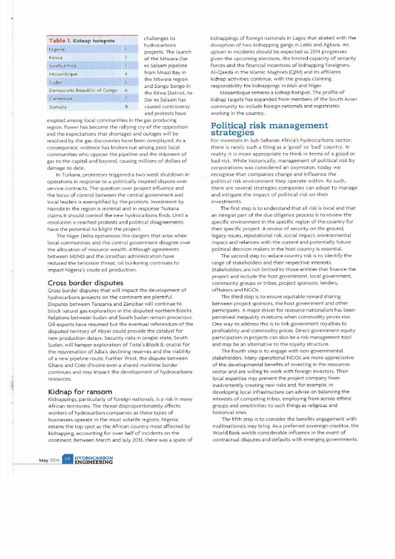
Table 1. Kidnap hots pots
chatlengesto
Nigeria
hydrocarbons
projects. The launch
enya
2
of the Mtwara Dar
Sout h Africa
3
es Salaam pipeline
Mozambique
4
from
Mnazi Bay in
Sudan
5
the Mtw ara region
Democratic Republic of Congo
6
and Senga Songe in
the Ki[wa District, to
Camer
oon
7
Oar es Salaam has
Somalia
8
caused controversy
and protests have
erupted among local communities in the gas producing
region. Power
has
become the rallying cry of the opposition
and the expectations that shortages and outages will be
resolved
by
the
gas
discoveries have been overplayed. As a
consequence, vi
olence
has broken out among
poor
local
communit ies
who
oppose the pipeline and the shipment of
gas
to
the capital and beyond, causing millions of dollars of
damage
to
date.
In Turkana, protestors triggered a two week shutdown in
operations in response
to
a politically inspired dispute over
service contracts. The question
over project
influence and
the locus of control between the central government and
local leaders is exemplified by the protests. Investment by
Nai robi in the region is minimal and in response Turkana
claims it should control the new hydrocarbons finds. Until a
resolution is reached protests and political disagreements
have the potential to blight the project.
The Niger Delta epi tom ises
th
e d,mger > that arise when
local communities and the central government disagree over
the allocation of resource wealth. Although agreements
between MEND and the Jonathan administration have
reduced the terrorism threat, oil bunkering cont inues
to
impact Nigeria s crude oil production.
Cross
borde
r d
is
putes
Cross border disputes that
will
impact the development
of
hydrocarbons projects
on
the continent are plentiful.
Disputes between Tanzania and Zanzibar will continue
to
block natural
gas exploration in
the disputed northern blocks.
Relations between Sudan and South Sudan remain precarious.
Oil exports have resumed but the eventual referendum
ofthe
disputed territory of Abyei
could
proVide the catalyst for
new production delays. Security risks in Jonglei state, South
Sudan, will hamper exploration of Total s Block B, crucial for
the rejuvenation of )uba s declining reserves and the viabi l ity
of a new pipeline route. Further West, the dispute between
Ghana and Cote d lvoire over a shared maritime border
cont inues and may impact the development of hydrocarbons
resources.
Kidnap for ransom
Kidnappings. particularly of foreign nationals,
is
a risk in many
African territories. The
threat disproportionately
affects
workers
of
hydrocarbon companies
as
these types
of
businesses
ope
rate in
the most volatile
regions. Nigeria
retains the top
spot
as the African
country
most affected by
kidnappi n
g,
accounting for over half of incidents
on
the
continent. Between March and July 2013, there
was
a spate of
kidnappings of fore ign nationa ls in Lagos that abated with the
disruption of two kidnapping
gangs
in Lekki and Agbara. An
upturn
in incidents should be expected as 2014 progresses
given the upcoming elections, the limited capacity of security
forces and the financial incentives of kidnapping foreigners.
AI·Qaeda in the Is lamic Maghreb (QIM) and its affiliates
kidnap act ivities continue, wi th the groups claiming
re sponsibility
for
kidnappings in Mali and Niger.
Mozambique remains a kidnap hotspot. The profile of
kidnap targets has expanded from members of the South Asian
community to include foreign nationals and expatriates
working
in
the country.
Politica.1 risk
management
strateg es
For investors in
Sub
-Saharan Africa s hydrocarbons sector,
there is rarely such a thing
as
a good
or
bad
country.
In
reality
it is
more appropriate to think
in terms of a good
or
bad risk. While historically, management of political risk by
corporations
was considered
an
oxymoron
,
today
we
recognise that companies change and influence the
po l
itical risk environment they operate w ith in. As such,
there are several strategies compan ies can
adopt
to manage
and m itigate the impact of political risk on their
investments.
The first step is to understand that all risk is local and that
an integral part of the due diligence process is to review the
specific environment
in
the specific region
of
the
country
for
their specific project. A review of security on the ground,
legacy issues, reputat ional risk. social impact. environmental
impact and relations with the current and potentially future
political decision makers in the host country is essential.
The second step
to
reduce country
risk is to
identify the
range
of
stake holders and their respective interests.
Stakeholders are
not
l imited to those entities that finance the
project
and include the host government, local government,
commun ity groups
or
t ribes,
project
sponsors, lenders,
offtakers and NGOs.
The
third
step is
to
ensure equitable reward sharing
between
project
sponsors, the host government and
other
participants. A major driver
for
resource nationalism has been
perceived inequality
in
returns when
commodity
prices rise.
One way
to
address this is
to
link government royalties
to
profitability and commodity prices. Direct government equity
participation in projects can a
ls
o
be
a risk management
tool
and may be an alternative to the royalty structure.
The fourth step is to engage with non-governmental
stakeholders. Many operational NGOs are more appreciative
of the developmental benefits of investing in the resources
sector and are wil l ing to work with foreign investors. Their
local expertise may prevent the project company from
inadvertently creating new
risks
and, for example, in
developing local infrastructure
can
advise on balancing the
interests of competing tribes, employing from across ethnic
groups and sensitivities
to
such things
as
religious and
historical sites.
The
fifth
step
is to
consider the benefits engagement
with
multinationals may bring.
As
a preferred sovereign creditor, the
World Bank wields considerable influence
in
the event of
contractual disputes and defaults w i
th
emerging governments.

7/21/2019 Hydrocarbon Engineering Mayo 2014 Vol 19 05
http://slidepdf.com/reader/full/hydrocarbon-engineering-mayo-2014-vol-19-05 18/107
NE
LI K

7/21/2019 Hydrocarbon Engineering Mayo 2014 Vol 19 05
http://slidepdf.com/reader/full/hydrocarbon-engineering-mayo-2014-vol-19-05 19/107
This influence is reinforced by the
World
Banks s role
as
a
key source of liquidity when a country is in turmoil.
The sixth step is to consider recourse under bilateral
investment treaties BITs) which have long provided a
valuable source of risk mit igation and valuable safety net to
counter
the
worst
excesses of government behaviour.
The seventh step is to provide adequate
protection fo
r
personnel.
In
con j
unction with
ensuring operational
continuity,
companies
owe
a basic
duty
of care to
their
employees and must ensure that suitable secur ity plans are
implemented
and regularly reviewed to minimise the risks
of
an
incident
occurring.
Risk
cannot be
complete
ly
removed
from
a
pro
j
ect
and should an event happen
the
company needs
to
have
an
effective cr isis plan in place.
which
will
include access to specia
li
st
third party
service
providers
for
medical
or political
evacuation
or
kidnap
response .
The eighth step in
the
r isk management process is
to
insure these risks. Political risk insurance PRI) can insure
against loss
to
foreign lenders, investors, suppliers and
traders with mining companies. There are a range of perils
that these risk participants may be exposed to depending
on the specific
project
. the basis on which it t rades, the
location and associated
contractual
agreements.
A key issue that is
often
misunderstood when looking at
political
r
isk
in the hydrocarbons sector is the idea that the
key asset to be insured is the mineral reserves.
In
the
private
sector the asset is in
fact
the right to explore
for
HYDROC RBON
NGIN RING
and receive a share of the revenue derived from natural
resources, not an ownership right over
those
resources.
This means that the fundamental peril for investors in and
lenders to resources projects is
often
the repudiation of
the operating agreement by the
host
government and not
the con f iscation of the mineral assets. This is crucial in an
era where government action may take different forms
that
are
not
of
the character
of
expropriation
as
has
been
traditionally understood but
do
constitute
a repudiation of
existing operating agreements,
often through
a process of
creeping expropriation .
The private PRI market, comprising
of
nearly
S
syndicates and companies,
has theoretical
capacity
for
a
Sing le
project
in excess of
USS
1 bil lion. Securing this
capacity and agreeing
conditions
and a
competitive
price is
most
successfully achieved by demonstrating clear
identification of the underlying perils and
appropriate
risk
management. Political risk
underwriters
of resource
projects pay careful attention
to
due diligence and
do
distinguish between
the
qualities
of
similar projects in
the
same ter ritories.
onclusion
PRI
will
not fix a bad deal
or
contr
act
but when a project is
well structured and the correct PRI coverage purchased, it
effectively neutra l
ises
country risk and prOVides an
effective safe
.
net
for
Sub-Saharan Africa hydrocarbon
investments.
i '7I
7/21/2019 Hydrocarbon Engineering Mayo 2014 Vol 19 05
http://slidepdf.com/reader/full/hydrocarbon-engineering-mayo-2014-vol-19-05 20/107
fast
returns
PL NT
H R
MONTHS
F STER
WITH
UOP RUSSELL
FACTORY-BUILT PLANTS
Quickly
ma
ximize
the
value of natural gas assets
with
NGL recovery
solutions from UOP.
Get cash flow
and
profits sooner with
hydroca
rbon management solutions from
UOP including the UOP Russellline
of
complete, modular, factory-built systems
that are
designe
d to h ve you up and running six months
quicker
than o ther
options. The reduced on-site installation time, proven designs
and
pre-fabricaled
solutions can deliver an earlier starlup al a lower cost than stick-bui lt facilit ies.
Or choose the UOP-Twister€ Supersonic Gas Separation System, with a small
footprint and low maintenance that s often ideal
fo
r remote
and
offshore facili ties.
Or get
maximum NGULPG r
ecovery
- an industry-leading
99+%
- with solutions
from UOP and Ortloff Engineers, Ltd. In short, whether you need fast, compact ,
efficient
or
all of the above, UOP has a solution for your NGL -r
ecove
ry nee ds.
A Honeywell Company
1914 .
2014
A Century of Inno
va
ti on
in the Oi l and
Ga
s Indu stry
F
or
more information about UOP Russell solutions, visit www.uop.com uoprussell
or
visit
www.uop.com
to learn about all of the UOP hydrocarbon managemen t solutions.
©
2014 Honeywell International, Inc. All rights reserved.

7/21/2019 Hydrocarbon Engineering Mayo 2014 Vol 19 05
http://slidepdf.com/reader/full/hydrocarbon-engineering-mayo-2014-vol-19-05 21/107
ay2 14

7/21/2019 Hydrocarbon Engineering Mayo 2014 Vol 19 05
http://slidepdf.com/reader/full/hydrocarbon-engineering-mayo-2014-vol-19-05 22/107

7/21/2019 Hydrocarbon Engineering Mayo 2014 Vol 19 05
http://slidepdf.com/reader/full/hydrocarbon-engineering-mayo-2014-vol-19-05 23/107
Figure 1.
U P
Russell
modul r
fractionation pl nt
in the Marcellus gas basin.
distribution
infrastructure. This can be part icularly
true
of
shale
gas, as the composition
can vary significantly
from
one
field to another. Additionally shale gas resources can exist
in remote regions challenged
by
limited water,
infrastructure
, and
other logistical
challenges requiring
innovative
processing solutions.
As
in
the
us
shale
gas
revolution, exploration and production (E P) companies
need to partner with
solution
prOViders
to
assure they can
monetise their resources in a timely, capital efficient
manner. Project success often hinges on executing gas
projects qUickly t reduced cost compared to traditional
methods, as well as ensuring
the
projects can maximise
the
recovery of high value NGL products
at low production
costs and downtime.
Shale gas in the US has rapidly increased as a source
of
natural
gas.
Led by new applications
of
hyd raul ic fracturing
technology and horizontal drilling, shale
gas
new source
development has offset
declines in production
from
conventional gas reservoirs and has led to major inc reases in
reserves of
US
natural
gas
. Largely due to shale gas
discoveries, US dry natural gas proved reserves have
more
than doubled
from 164 000 f t
in 1998 to
334
000 f t
in
2011,
with
more
than 70 of this increase due to additions
after
2006. The
economic
success of shale
gas
in
the
US
has
led
to
development
of shale
gas in
Canada. and more recent ly,
has spurred
interest in
shale
gas
possibilities in China,
Europe, Asia, and Australia. US shale
gas
continues
to
change
the
energy mix w
it h
in the
country
and
has
a substant ial
impact
on US energy se lf suffiCiency.
The rapid
growth in
shale
production,
especially
in
geographically diverse locations
from traditional
production, has
led
to the
need
for
a rapid expansion
of
midst
ream
asse
t
s.
This rapid expansion required a
strong
partnership between operators
and supplie
rs
to
focus a
large
portion
of
the us eqUipment production capacity on
designing, installing and operat ing these new plants in
parallel with field developments and
gas production
estimates.
The parallel processing of production assets and gas
processing facilities made it particularly challenging to
design new facilities based on
gas
quality
info
r
mation
from
a
few
initial wells. It was also challenging to be flexible
7/21/2019 Hydrocarbon Engineering Mayo 2014 Vol 19 05
http://slidepdf.com/reader/full/hydrocarbon-engineering-mayo-2014-vol-19-05 24/107
while
dealing
with potential
variations as
more
wells were
dril led in the
same
area.
n
addition, operators often wanted
to design gas processing plants before
they
had detailed gas
compositions from
pilot wells. This
uncertainty
in
future gas
quality adds
to the complexity of plant
design and can
increase the risks
assoc
iated with the profitabilit y of overall
field development.
Gas processing options
Unconventional gas is often contaminated with
l
and
removal is required when the produced gas contains higher
levels than
the
downstream pipeline
wilt
accept, which is
typically 2 - 3
%. In addition
, when NGL recovery
is
desirable,
cryogenic systems will require CO
concentrations to be
lowered to approximately 0.5 -1 , depending on the richness
of
the gas
and
the
level
of
NGL recovery desired. High levels
of
CO
can lead
to
freeze out
at the
normal operating
temperatures
below
-
125 O
Y-Grade NGL specifications
for
cryogenic l iquid
production
normally
limits CO
to
0.35
LV%
CO
or 1000
ppmw
. The ri
ght technology
for acid
gas
removal depends on
the
amount
of
acid
gas
in the feed and
the
desired contaminant level
in
the
product. The most
common processes for removing CO
are amine treating,
membranes and a molecular sieve.
Conventional and unconventional
gas will
be water
saturated at
the temperature pressure where
the well is
produced. This water vapour must be reduced to avoid
corrosion and freezing in downstream processing units and
pipeline distribution networks.
The
most prevalent solutions for
pipeline gas is contacting the gas with 99 /0 triethylene glycol
(TEG)
to
dry the gas to below 7 Ibs/OOO
ft'.
Cryogenic NGL recovery wilt
require deeper drying in a molecular sieve unit
to
dry the
gas to
below 100 ppmv
NGLs contained
in
shale
gas
provide an economic incentive
for
recovery beyond just treating
for
pipeline
sale.
These NGLs
are recovered fo r refinery, petrochemical or other distributed
fuel
uses
where their value exceeds what
is
recoverable on a
strictly British thermal units
(Btu)
basis than if the NGLs
are
left
in
the natural gas stream. Local market conditions can vary
Significantly
with
regard
to
ethane and liquid petroleum
gas (LPG)
values.
In
many new shale gasfields, there
can be
Significant local
price dislocations due to lack of takeaway capacity for specific
products. This requires a flexible cryogenic plant design if the
operator wants
to
react
to
local market conditions and maximise
profitabi li
ty
from shale production.
he
modular plant
solution
The 'fast gas' rapid NGL recovery
model
has enabled the
shale gas revolution by aligning supplier capabilities and
operators' needs for rapid and economical development
of
new shale production. The rapid increase in dry shale
gas
production
placed
downward
pricing pressure
on
natural
gas
to the point that dry natural gas was 'borderline' economical
for operators.
At
this point, attention shifted to wet
gas',
or
shale
gas
that contained Significant volumes
of
NGLs
that
command a market
pr
ice
tied to
crude
oil that is
higher than
7/21/2019 Hydrocarbon Engineering Mayo 2014 Vol 19 05
http://slidepdf.com/reader/full/hydrocarbon-engineering-mayo-2014-vol-19-05 25/107
natural gas prices. The traditional plant delivery model, which
takes two
or
more years
to
implement created a costly delay.
This formed a barrier
to
develop these vital resources.
Just as George Mitchell developed hydraulic fracturing, an
entrepreneur emerged with a solution. This entrepreneur was
Tom Russell. He developed a model
of
providing
preengineered factory built modular plants
that
enabled the
delivery and installation
of
NGL recovery plants at least six
months faster than
the
stick built alternatives. In addition the
Russe
ll approach did
not
require the operator
to
know exactly
how
rich his gas stream was upfront Pl
ant
fabrication
Quld
occur in parallel to drilling, fracturing and
well
testing. For
operators developing new resources, these new capabilities
to
parallel the field and plant development processes were
critical
to
bringing
on
new assets quickly. They also provided
a rap id return on the large capital outlays required
to
meet
growing shale development .
Speed
is of
the essence in the midstream business mode l,
and the typical stick built project timel ine can run 24 months
from plaCing the order to seeing plant startup.
In
part, this is
because a sequential process
is
required,
from
a
completed
gas analysis to
the
design
of
equipment starts in front end
engineering and design
(FEED).
After design
is
completed in
FEED,
procurement
can
order long lead equipment. FEED and
procurement are sequential steps in
the
stick built project.
However, modular plants provide a faster alternative by
integrating FEED and procurement activit
ies to
optimise
ove rall
project
schedule and profitability Some equipment is
preengineered to start procurement from day one, even
before gas analysis is necessarily available. Once gas ana lysis is
known, i
mportant
value added equipment is optimised for
the
project. Efficient value added optimisation allows FEED and
procurement
to
be integrated
in
a single, seamless process.
These modular plant project innovations enable starting a
plant s first gas' up to six
mont
hs sooner than with stick built
solutions.
The sk id mounted equipment can provide greater mobility
in challenging locations. Remote locati ons with
limited
resources. restricted access and
other difficulties
are more
eaSily overcome. Ideal candidates for modularisation are
packaged units sized
for
up to 300 000 ft
3
/ d of volume. with
even larger plants accommodated by mu l
tiple
trains. These
systems are integrated in a shop setting befo re being shipped
to
the plant
si
t
e.
This provides assurance that equipment will
assemble qUickly, fit up properly at the field site , and ensure a
smooth and rapid installation, commiss ioning and startup.
PlaCing
the plan t on stream faster and recover ing NGLs
sooner is quite valuable. A typical example of a 200 000 f t
3
d
plant
with a moderate NGL content (3 gal /m in) will generate
more
than US 10 million
of
additional value each month in
recovering the NGLs
at
current prices as opposed
to
leaving
them in
the gas
and receiving heating value. Earl ier delivery by
six months cou ld
potentially
be worth more than
US 60
million. which can be 50% of
the total
installed
cost
of
the full
plan t. Rap id NGL recovery is vital in
imp
roving the
overall process economics of the shale
gas
and liquid
hydrocarbon value stream.
Modularised plants
in
action
Some
of
the rea l life applications
seen
across the
US
shale
basins in the last few years showcase the unique challenges
HYDROC RBON
ENGINEERING
customers face. For example,
flat topography in
t he Eagle
Ford might be replaced by more mountainous terra in in the
Marcel lus. High altitude
areas
such as the San Juan
Basin can
be contrasted
wi t
h lower lying areas in Louisiana. Some
areas
produce lean gas
with
low
to
moderate levels
of
NGL. and
some
areas
have high levels
of
NGL that demand mo re
recovery with associated equipment.
Case study
one
In the Marcel l
us
Shale Basin, an
operator
acquired a
120000 ft
3
d
cryogenic unit with a refrigeration package
to
process natural gas containing 6 - 7 gal /min . After startup,
the
customer determined that they had higher
gas
rates than
anticipated. The equipment supplier worked with
the
customer
to
find a so lution. designi
ng
a Aexible system that
would meet
their gas specifications. The customer was then
able to push gas vo lume
throughput
to
115% of design and
process
138 000 ft
3
/d Th
is enabled the client
to
secure more
gas contracts.
Since
the
installation of the first plant,
the
site has
increased f rom 138
000
ft
3
d
capacity
to
660
000
ft
3
d
by
adding two 200 000 ft
3
d
cryogenic un its
with
refrigeration
and a 120 000 f t
3
d
cryogenic
unit with
refrigeration. Because
of
this. the customer was able
to
break ground in a green fie ld
site and then expand into a major gas process ing hub for the
Marcellus area. The customer has returned
to
modular
solutions for additional gas processing needs.
Case study two
In the
Eag
le Ford Shale. an operator was aware that he had to
process up to 600
000
ft
3
d of g<lS
within u two year
timeframe. The operator partnered with the equ ipment
supplier
to
make certain
that
they
cou ld achieve this w i
thout
cons uming the time it would take to construct a stick built
plant. Adopting a modular approach saved
time
in project
t imeline execution and made rapid NGL extraction a real ity.
The first 200 000 h
3
d cryogeniC plant installat ion was
finalised in the thi rd quarter of
2012
. The second
200000 ft
3
d
cryogeniC installation was finalised in the fi rst
quarter of 2013, and
the
final cryogeniC 200
000
ft3 d
instaHation will be finalised in
the
first quarter of
2014
. One
benefit of this schedule was
that
equ i
pment
was installed as
gas demand ramped up, which
only
a modular approach
can
do. Another benefit was
that
t he
operator
had th ree identical
plants with the same list of
common
spare parts. This signifies
a greater mai ntenance fam il iarity as more plants came on line.
The operator could then purchase common compression for
each trai n. leading to a more homogenous operation.
onclusion
Whe n delivered by an experienced sol ution provider,
solutions for CO
2
removal. dewpo inting and NGL recovery
can be delivered as prefabricated, skid mounted modules that
provide feed composit ion flexibi lity and rapid NGL recovery.
This lowers fabrication costs, speeds installat ion and provides
high onstream effiCiency. Modular, prefabr icated solutions
enable economic development of sha le
gas
resources that
would
otherwise pose
as
daunting processing challenges
given thei r inherent variabi li
ty in gas
compos ition. Operators
using this modular approach truly benefit
more
efficient operations and optimal monetisation.
iI
7/21/2019 Hydrocarbon Engineering Mayo 2014 Vol 19 05
http://slidepdf.com/reader/full/hydrocarbon-engineering-mayo-2014-vol-19-05 26/107
Eric Wiley and Hung-Ming Sung, Trinity Consultants,
USA, and Arun Kanchan, Trinity Consultants, Qatar,
discuss best practice
in
emissions monitoring.
I
ndustrial facilities subject to regulatory
emissions limits and air quali ty
permit
conditions must frequently
implement
sophisticated continuous emissions monito ring
systems EMS) to demons trate compliance with the
applicable limits. Data
from the monitoring
equipment
is
used
to demonstrate compliance
with
applicable
emissions limits and standards, either concentra tion
based limits/ standards e.g., ppm. ppb) or mass based
limits/standards e g
,£/hr, £/d
for pollutants such as
sulfur dioxide
(S02) oxides of
nitrogen (NO),
carbon
monoxide
(CO),
total hydrocarbons [THC)/vOC - 0
lead, carbon dioxide (CO
,),
and particulate marter (PM),
Including
PM Q
and
PM2.5.
CEMS
essenti ls
The EMS sampling system continuously extr cts a
representative sample of stack
gas
from a process
unit
to
the monitoring equipment th t includes
various analysers. Once the gas sample has been
analysed, the associated results are fed into a data
acquisition and handling system
(DAHS)
that
processes the voluminous data and outputs to the
facility's reporting system.
Regulatory agencies reqUire th t the (EMS data
demonstrate compliance with monitoring, record
keeping. and reporting requirements. Prior to
specifying, installing, and implementing a (EMS, the
operator should have a firm understanding of the
applicable regulatory requirements. Ongoing
operation of an effective (EMS program th t
consistently meets compliance requirements also
requires significant effort related to quality control,
maintenance. training. auditing, and reporting. The
level of effort associated with these tasks requires
speCialised expertise and an organised, well defined
approach.
Available CEMS technology
There are four major types of (EMS systems. each
with benefits and drawbacks depending on the
industrial scenario. Dry extractive systems are used in
7/21/2019 Hydrocarbon Engineering Mayo 2014 Vol 19 05
http://slidepdf.com/reader/full/hydrocarbon-engineering-mayo-2014-vol-19-05 27/107
a variety of industr ies including petrochemical, refining, power,
steel, and cement. Approximately 55 of (EMS which measure
NO
x
are dry extractive (EMS. Although this equipment
performs well at both high and low concentrations, is versatile,
and easily maintained,
it
is relatively expensive to purchase
and to maintain. Dilution extrac tive systems have been
historica lly used largely
for monitoring
502 on coal fired units
and
on
dusty emissions sources with high
PM
in the sample
such as cement plants. These systems are easily maintained
and someti
mes
less expensive however they are less effective
for lower concentrations, require more maintenance on the
stack, can be
difficult
to troubleshoot, and cannot measure
oxygen levels.
With wet
extractive
CEMS
, the sample
is
delivered to the
analyser above dew
point
useful for incinerators where acid
gases
are present (HCI,
HF).
These systems are relatively easy
to calibrate and require minimal sample conditioning.
However. performance of these units at low concentrations is
challenging. In situ CEMS are located at the source of the
exhaust (on the stack). These units analyse the exhaust in
or
across the stack
or
duct
without
extracting and treating a
sample for analysis.
Examples of in situ systems include fourier transform
infrared
FTIR)
systems,
flow
measurement systems using
ultrasonic technology, and thermal senSing. Fast response
time, lower cost and lower maintenance requirements
for
these units are offset by shorter life spans due to
environmental exposure, maintenance difficulty, poor
accuracy. and calibration difficulty.
A qualified CEMS supplier can a Ist with the selection of
the most suitable equipment
as
well
as
its installation and
certification,
however the development
of
an
adequate
quality assu rance and quality control
(QA/QC)
and
maintenance plan, ongOing training, reporting, and auditing
remain largely the responsibility of the facility.
EMS
d t
qu lity m n gement
Environmental permits
that
requi re
CEMS
to demonstrate
compliance include provisions for ensuring data quality. In
fact. QA/QC programs are the backbone
for CEMS
compliance
with
regulatory requi rements. While quality
assurance pertains to ensuring the accuracy and reliability
of
the
emissions data (via proper planning and f requent audits),
quality control includes the activities involved in maintaining
or
improving
the
accuracy and reliability of
the
emissions data
(via
routine
calibrations and preventative maintenance).
Developing appropriate QA/QC procedures, establishing
missing data substitution provisions, and specifying
DAHS
calculation procedures are just a few key elements of an
effective
QA/QC
program. Regulatory requirements for
CEMS QA/QC vary, but all include tasks such as daily
calibration, linearity tests
or
calibration
gas
audits (CGAs), and
relative accuracy test audits RATAs). Furthermore, data must
be accurate, representative, reliable, complete. and precise, as
defined by applicable regulations.
EMS
m inten nce
progr ms
An effective CEMS maintenance program that prevents
breakdowns
is
essential to provide accurate and reliable data
for
compliance
with
applicable air quality regulations. The
HYDROCARBON
ENGINEERING
preventive
ma
intenance PM) program should be organised,
scheduled, and efficient. Tasks are scheduled by frequency
(daily, weekly, etc .) and should include logging of the status of
tasks
(completed/not
completed) and
the
responsible person.
In
the case of daily calibrations, the operator should ensure a
quick response to failed calibrations,
monitor
and record
calibration t ren
ds,
and
for
facilities
with
multiple
CEMS
,
stagger the schedu led daily calibration times. Other
maintenance tasks should be scheduled to avoid conflict
with
auto calibrations, to maximise data collection , and to minimise
downtime. Prior
to
initiating any preventative
or
maintenance
acti v
it y
,
it is
important to place the system
into
maintenance
mode. This
will
mark
the
associated data with a maintenance
flag, thus preventing the data from being used in hourly
averages. likewise
,
the
system must be taken out of
maintenance mode immediately following any maintenance
activity.
As
part of
the
PM
maintenance activit ies,
the
CEMS
operator
should visit each (EMS shelter daily and record the
following parameters in the log
book
, where applicable:
•
Outlet
pump pressure.
• Sample system vacuum.
• Sample
flow
to analysers.
• Temperature.
• Presence of alarms or faults.
• Cooler temperature.
• Peristaltic pump status (on or off).
The log book provides a perfo rmance history of
the
system, information on previous issues, and how those
is
sues
we re resolved. It also provides a record of trends in flow,
vacuum, pressure, and temperature. Some facilities maintain
CEMS
performance history through the
use of
digital
maintenance forms which are
often
more detailed and can
be enabled on mobile dev i
ces.
Weekly activities include recording analyser
test function
readings, such as slope and offset, recording calibration
gas
bottle
pressures, replacing
calibration
gas
bottles if pressure
is less than
150
- 200 psi, and monitoring for trends in daily
calibrations, adjusting zero and span
if
needed.
Monthly PM
includes all of
the
daily and weekly tasks
as well as
preparing
for any upcoming audits such as RAT
As,
(GAs,
or
linearity
tests. It is also a
good
interval
to
check the status of air
conditioning filters and plant air filters and
to
make sure
the
ai r conditioning unit is in good working order, especially in
warmer areas
or
times of the year.
Quarterly requirements
for
CEMS include the completion
of linearity tests, (GAs, and
N0
2
converter tests. The results
of these tests can be used to improve accuracy and
reliability, thus improving data availability. Annually, many
(EMS consumables have reached the end of
their
'service
life and must be replaced. Activities include probe
maintenance (replaCing o-rings and bushings) and replacing
per istaltic pump tubing as we ll as the pump diaphragm and
gaskets.
CEMs
maintenance programs should be reviewed on a
frequent
basis
to
ensure
that they
comprise
the
appropriate
tasks. An audit
of
the program can assist in improving
effectiveness and effiCiency
as
well
as
highlighting areas
of
positive achievement. Annual
or
bi annual auditing is useful

7/21/2019 Hydrocarbon Engineering Mayo 2014 Vol 19 05
http://slidepdf.com/reader/full/hydrocarbon-engineering-mayo-2014-vol-19-05 28/107
to identify
deficiencies in
compliance or provide
assurance
of
continuing compliance.
DetermininR <;;EMS
accuracy
and system-bIases
Primary performance testing for EMS is conducted via the
RATA
on
a
sc
hedule agreed
upon
with
the
regulatory
agency. The RATA is a compara tive evaluation of
the
EM
system performance
aga
inst
an independent
reference
method.
The US EPA reference
methods
typically used are as
fo l
lows :
• Method 2 (reference
method
fo r
determination
of stack
gas
velocity and volumetric flow).
• Method
6(
(instrumental r
efe
rence
method
for SOJ
• Method 7E (instrumental method for NOJ
In a RATA, a minimum
of
nine sets
of
paired
monitoring
system and reference method
test
data are obtained. Data
from the
RATA are used to
determine
both
the
relative
accuracy and bias, jf any,
of
a
EM
system.
Systematic and
random
errors can
occur
in a l
of the
subsyst ems and components of a EM system. The ski l and
experience
of
the EM system manufacturer, integrator, and
operato
r are requi red
to
minimise biases and
ob t
ain the best
possible accuracy and precision. It is then the responsibility
of the
EM system
owne
r and
ope
rator to maintain
the
system to specified levels
of
accuracy and precision.
Specifically, bias problems can be associated
with
the
following:
• Sampl i
ng locat
ion and stratification,
E M S ~
. . . .
_.,.-
' , ... 1140<. .
_ M ~ : . . , ~
I
,
,
,
j ' - -
SO. T.. I
1.0.:....
I
S v.od,,,"
I
,
,
,
,
,
,
C
EMS
I
....".'.,<01 • Y1
,
,
CEMSO .. P . . . u.
RTOS
' ,'
,
nou
..
.
.........
.'
"
.
0,,, ..... ...
''''9.,,..,.....
•
'-.
..
R"", S
06,,,
R
.
-r
...
O
..
"
S '''T .
M . . . . ••
.
u
.
L.> G V
....
000._,,_,
( '1 . . . . . .
R
. . . . .
a .. ...
l,,,G'''''V>kI.
•
,-
x ... '.
I
R.. ,a .. I ...
o .
Volut
Figure
1. CEMS
data validation, calculation
and
reporting with a fully integrated
RTDB.
•
Dilution extractive
system bi
ases.
• Source level extractive biases.
• In
si
tu
gas
and f
low mo
n itor biases.
• Pollutant and diluent analyser biases .
• Data acquisition and handling system problems
Compliance report
ing
In (EMS, the data acquisition and handling system (DAH
S) is
the brains
of
the ope ration. The DAH5 receives emissions
data from the programmable logic
controller
(PLC) or data
logger and arranges it according
to
programs demands. Some
compan ies. subject
to
acid rain
reporting
requirements ,
We
support the energy industry from every angle
to
ensure effective
air quality strategy and streamlined EH S data management

7/21/2019 Hydrocarbon Engineering Mayo 2014 Vol 19 05
http://slidepdf.com/reader/full/hydrocarbon-engineering-mayo-2014-vol-19-05 29/107
It s what
we do
otoform single step
sulphur solidification
Unrivalled reliability, direct-from-th e-mclt solidification
and environmentally friend ly operation have
mad
e
Ro
roform the world's favourite su lphur solidification
process .
Add end-to-end
process
capab
ility - from receipt
of liquid sul phur to sto rage, handling and loading - and
it's clear why the refinery world chooses Sandvik.
• Ou tstand ing reliability -
on-stream
factor of
96
• Premium Rotoform past illes - low dust, low moisture
• Clea n, indirect cooling - no cross-cont
ami
na t ion
• Single source, end-to -end capability
Sandvik Process Systems
Divis ion of Sandvik Mat erials Technology Deutschla nd GmbH
Sa lierstr.
35. 70736
Fellbach.
German
y
Tel: +49 7
1 510$-0 '
Fax:
+49 711 5105-152 . info.spsde:@sand ikcom
ww w.processsystems sandvik com
install DAHS
for
reporting, However, many companies
introduce
the (EMS data
to
their existing plant real
time
database RTDB), such
as
the OSlsoft
P
system,
to
enable real
time
monitoring of the (EMS. These RTDB systems normally do
not perform data substitution, calculate emissions,
or
create
comp
l iance reports. This is the area of the
(EMS
in which most
non-compl iance issues are discovered.
Data acquisition and handling is not a
do
it yourself task;
rat her,
the
facil ity should purchase
and/or
implement a
system with proven reliab il ity and capabilities to generate
proper reports. The typical DAHS
is
designed to handle
missing data and calculations
within
the (EMS data. Using an
RTDB
with process data, (EMS data can be further validated
with the process operation conditions and can generate
emission calculations when
the
(EMS
is
down.
Figu
re 1 shows
a fu ll y integrated
RTDB
wit h real time data validation and
reconciliation process, The shaded boxes represent typ ical
RTDB
calculations
. The
validation
steps are added
to
generate accurate reconc iled data. These data
treatment
processes are critical for ensuring reported emissions are
accurate, assess ing data availability calculations, and
affirming
data substi
tu t
ion procedures.
Additionally, while reporting
to
the regulatory agency,
the results from the bias test conducted as part of
the
RATA
must
be considered. The bias test
determines
whether a
monitoring system
is
biased low with respect to the
reference method, based on the RATA results. This test is
required only for S0 2
NO
x
and flow monitor ing systems. If a
low bias
is
found, a bias adjustment
factor
BAF) must be
ca lculated and applied to the subsequent hourly emissions
data.
Essential training
A final e lement necessary
for
proper operation
of
(EMS
is
train ing. Both environmental managers and facility operators
should understand applicable air quality requirements inc luding
how to effectively and appropriately operate (EMS units.
Nearly all analyser manufacturers offer training
for
their
equipment. Although this training may be costly, it should be
considered
for
any technician who will be responsible
for
a
(EMS as the inS ight and knowledge gained will assist in
increasing (EMS data availabil ity. When a new (EMS is installed,
it
is important to ensure the (EMS manufacturer provides
training on proper operation of
the
(EMS to all personnel who
will have a ro le in the CEMS operation, maintenance and
reporting.
Conclusion
As regulatory requirements are increasing the use of (EMS
to
demonstrate compliance, creating and maintaining a successful
(EMS program can be a daunting task for
any
environmental
profeSSional.
Ensuring
the most appropriate type of (EMS is being
used, from among the various types that are available, is essential to
demonstrating compliance with applicable regulations. (reating a
structured and well defined (EMS QA/Q progr
am
is also
important for complying w ith applicable regu
la
t i
ons.
A well
organised
and
executed PM program will assist in maximising the
performance and reliability of the (EMS and the data availabi lity.
Understanding t
he resu
lts
of
RA
TA tests and the impl ications
of
using
bias adjustment factors while reporting
emiss
ions
to
reg
ulatory agencies is a must. Finally, having a welt trained
and
knowledgeable (EMS team is essential to the accuracy and
reliability of the (EMS data. i' 'I I

7/21/2019 Hydrocarbon Engineering Mayo 2014 Vol 19 05
http://slidepdf.com/reader/full/hydrocarbon-engineering-mayo-2014-vol-19-05 30/107
With laser scanning, we were able
to
minimize occurrences in
the
field to just a
handful. With safety an utmost importance,
the number of individuals entering the
plant
was also drastically reduced
We
were able
to
provide an enormous
amount
of data that
would not have been available through a conventional
survey effort. That same data provided benefit through
construction with the creation of isometrics and the
resolution of field issues and will provide a solid foundation
for lifecycle maintenance of the facility.
- David Stevens
Wood Group Mustang Piping Designer and Laser
Scan
Coordinator
eica
ScanStation P15
Mustang
laser Scanning/Special
Projects Group in reference to the the HessTIoga
natural gas
processing
plant TGP)
in northwestern
North
Dakota
HEX GON
;leiU
eosystems

7/21/2019 Hydrocarbon Engineering Mayo 2014 Vol 19 05
http://slidepdf.com/reader/full/hydrocarbon-engineering-mayo-2014-vol-19-05 31/107
IVN
CH NGE

7/21/2019 Hydrocarbon Engineering Mayo 2014 Vol 19 05
http://slidepdf.com/reader/full/hydrocarbon-engineering-mayo-2014-vol-19-05 32/107

7/21/2019 Hydrocarbon Engineering Mayo 2014 Vol 19 05
http://slidepdf.com/reader/full/hydrocarbon-engineering-mayo-2014-vol-19-05 33/107
Figure 1 Both global automotive emissions
legislation
and the
drive for energy sustain ability
are having an
impact
on refinery end products.
In
this industry, R D to improve the environmental
performance
of
vehicles
demands
substantial investment A
high level of technical complexity is involved, with great
reliance on first and second tier suppliers, who are among a
vast number of partners in the automotive value chain.
Therefore when
all
these technology partners work towards
a clear and common target, such as limiting the amount of
CO
2
or nitric oxide
emitted
from a car, the fragmented value
chain al igns all its resources to achieve this common
objective.
Another common benefit of legislation
is that it
creates
an enabl ing envi ronment
for
cost
effect
ive
transfer
of
technology, by broadly communicating best practice to
achieve the required changes,
for
example,
offering
gUidance on
the
latest analytical measurement
instrumentation.
An
excellent example of technology transfer is the
Euro IV, V and VI emission standards
developed for
European
markets
that
have been
adopted
elsewhere
in
the world,
for
example South Korea and China. Europe has successfully
prescribed targets and adopted relevant and useful
technology to
achieve targets, and this
effective
approach is
being replicated elsewhere.
Today there are three main global legislation groups
related
to
automotive emissions
coming
out of Europe, the
USA and Japan. European legislation is already progressing
towards Euro VII, while in the
USA,
the Environmental
Protection Agency (EPA) takes a leading ro le. The USA also
has federal environmental legislation, as well as certain
state specific regu lations and one of the most common
terms, ultra
low
emissions vehicle (ULEV) , in fact. derives
from Ca l iforn ia state legislation. There
is
also a formidable
legislative movement in Japan, since a large number of
automot
ive producers originate in
that
country. China,
however, which also has a substantial automotive industry
in terms of the number of
production
centres, tends to take
its cue from European legislation.
So,
what are
the common
goals of all this disparate
geographical legislation? Firstl
y,
legisl
ation
seeks
to
drive
fuel
economy
by
developing
more economical ways
to
move
people
and goods from A
to
B, in order
to
conserve
the world s dwind l ing fossil fuel resources
for
future
Ma
y 2014
HYDROCARBON
ENGINEERING
generations. There are also ec onomic benefits associated
with th
e issue of fuel
economy
,
as
the
more economic
it is
to
move
people
and goods, the more competitive a market
will
be. The
other
key goal of legislation is
to
mitigate
the
effects
of damaging automotive emiss ions, such as carbon
dioxide,
on
climate change. This is also closely linked
to the
goal of fuel economy,
as
the less fuel we burn, the fewer
em issions are released into the atmosphere.
nvironmental impact
In terms of climate change the industry also looks at other
greenhouse gases with global warming potential (GWP). An
example is nitrous oxide, which has a much higher GWP than
CO
2
but
because it exists in relatively low quantities in the
atmosphere, it attracts less headline press.
Other
issues exist
around particu late matter and soot and there is a more
recent focus
on
minimising the emission
of
any substance
that
has
stratospheric ozone
dep
leting
potential
since
stratospheric ozone s role is
to
absorb potentially
harmfu
l
ul
traviolet
rays
from the
sun.
For the first time, greenhouse gases such
as CO
2
and
nitrous oxide are being included into
US EPA
protocol gases.
Not
that long ago, these greenhouse
gases
were introduced
in addition
to
what was previous ly referred
to as the
criteria
pollutants, the six most common air pollutants of concern:
ozone, carbon monox ide, nitrogen dioxide, sulfur oxides,
particulate matter and lead. This is a significant step forward
that
could even be described as a fundamental
evolution
in
legislation, not on ly towards
cont
rolling toxic gases, but also
those which contribute to global warming.
Automotive emissions such
as
nitrogen dioxide and
sulfur d
ioxide must
also be
controlled
to
pro
t
ect our
physical envi ronment. These emissions can react with
rainwater and create acid rain that damages forests and
bU
ildings, since it reacts with limestone and concrete to
co rrode structures. Ground water contamination
is
another
concern, since the chemicals benzene and methyl tertiary
butyl ether (MTBE), added to improve engine combustion
are also damaging when they are washed
down
in rainfall.
Public health
Wi
th
a strong historic
US EPA
focus on so called
criteria
pollutants, much automotive legislation has been structured
around
public
health issues, resu lting in tightening emission
targets.
t
is
noticeable
that
th
ere has been a tangible
move
from
purely
monitoring automotive emissions,
to
monitoring the ambient environment, including detecting
the presence of chemicals in the air that the public is
breath ing. A Significant section of legislation is mov ing into
prescribing exactly what should be measured in the ambient
environment, how often it shou ld be measured and in which
locations. And there is more data transparency around these
findings than ever before, giving the public real time access
to this
important
information.
Improving public health by controlling air quality
is
a key
focus of automotive legislation. Air qual
ity
must be
maintained
at
a level th
at
ensures
it
does
not
cause disease.
With this in mind, there is a contemporary focus on
minimising ground level ozone
that
has the
potential
to
damage the human respi
ratory
tract and is produced

7/21/2019 Hydrocarbon Engineering Mayo 2014 Vol 19 05
http://slidepdf.com/reader/full/hydrocarbon-engineering-mayo-2014-vol-19-05 34/107
They turned to Elliott
for planning
and
execution
The customer
turned to Elliott
because
they
understood that planning is everything
and that few companies can match Elliott in turnaround planning and
execution
Who will you turn to?
COMPRESSORS . TURBINES .
GLOB L
SERVICE
l
EUIOIT
fJJ)1JJfJfJ
£ ARA CORPORATION
VNM eIIion
turbo com
he world turns to Elliott.

7/21/2019 Hydrocarbon Engineering Mayo 2014 Vol 19 05
http://slidepdf.com/reader/full/hydrocarbon-engineering-mayo-2014-vol-19-05 35/107
principally by a reaction between nitric oxide and volatile
organic compounds (VOCs),
Carbon monoxide is a prevalent
gas in
automotive exhaust
systems that, in enough quantity.
can
damage the nervous
system, while formaldehyde
gas
is
categorised as a probable
carcino
gen
and,
like ozone,
has
the potential to
cause
respiratory problems. Benzene is a vac that
not
only
contributes
to
the ground level ozone problem. but is a
to
xic
chemical
and
pollutant
in its own right. It
is
a known
carcinogen
that
can
be
inhaled from the atmosphere or
absorbed into the human body by eating contaminated fish
and crops. Nitrogen d ioxide, ammonia and sulfur dioxide are
other
examples of gases that can cause health problems by
weakening the respiratory
sys
tem and rendering humans more
susceptible to illness. Chemicals like this must be reduced or
completely eliminated from automotive emissions.
ohesion
of the issues
Any legislation framework must address these problems
effectively, but how
do
these issues all cohere in a matrix?
On
the
issue of fuel economy,
the USA has two
sets,
or
tiers , of emission standards
for
light
duty
vehicles,
defined
as a
res
ult of the Clean Air
Act
Amendments of 1990.
Wi thin
the
Tier
II
ranking, there is a subranking ranging
from
BIN 1 -
10, with
1 being
the
cleanest (zero emission
vehicle) and
10
being
the dirtiest.
These standards
specifically restrict emissions of carbon monoxide,
oxides of nitrogen, particulate matter. formaldehyde and
non-methane organic gases (non-methane hydrocarbons).
President Barack Obama
has
recenLly called
for
America s
fleet
of trucks,
lo
rr
ies
and cars to be elevated
into the next
category
of
environmental cleanliness and fuel economy,
BIN 4. This target cascades down
to
automotive producers
to incentivise them to make sure
that
the average vehicle
being sold is
mov
ing
to
a progreSSively more fuel effic ient
future,
The changing legislative environment relat ing
to
fuel
economy
is
enabling the introduction of new generation fuel
types in a safe and consumer friendly manner.
In
the
US
all
eyes are on E15, fuel with a 15 ethanol blend, which will
soon be commercially introduced to that
market
This could
herald in a new era, enabling the production and sale of a
new generation of environmentally friendly fuels.
Many years ago it was decided to transition to un leaded
fue ls a decision principally taken to protect the catalysers
installed in cars
for
the enablement of nitric ox ide, nitrogen
dioxide and carbon
monoxide
emissions reduction.
With
catalysers becoming prevalent, legislation was needed to
facilitate the
introduction
of unleaded. And, to
limit
the
sulfur dioxide emissions
that
react
with
rain to create acid
rain, ultra
low
sulfur diesel was introduced.
However, legislation always needs to look ahead
holistically
to
possible consequences. so that the totality
and end result of changes
is truly
beneficial, This
is
because,
inevitably, as one problem is solved, there are consequences
of changes and in some
cases
it might even become a case of
out
of
the frying pan and
into
the
fire . Legislation wou ld
not
be effective if it had this effect on
automotive
producers.
Therefore in seeking
to
create change in a particular area, it
is essential to look at any secondary impl ications the change
HYDROCARBON
ENGINEERING
is
likely to create and to Simultaneously mitigate secondary
outcomes.
An example is the ambition to reduce nitrous oxide
emissions from car engines by converting oxides of nitrogen
simply
into
nitr
ogen itself. One way
to
achieve this is
to
harness a technolo
gy
called selective catalytiC reduction
(SCR)
that converts nitrogen oxides back
to
harmless nitrogen
gas,
us ing ammonia in the catalysers. However, in trying
to
resolve
the problem of ni trogen oxide emissions, urea is being added
to create ammonia in the cata lyser
and
this could potentially
lead
to
the secondary negati
ve
impact of ammonia as an
automotive emiSSion
gas.
Ammonia must now also be added
to the l
is
t of emissions that must be monitored.
Another secondary impact of emission legislation involves
carbon monoxide. The principle reduction of carbon
monoxide is achieved through catalytic converters to oxidise it
to CO
2
which is potentially a problem
in
its
own
right in terms
of global warming, but is considered preferable to emitting
carbon monoxide. These catalyt iC converters in turn reduce
the overall fuel economy
of
the engine, so there a
compensating increase
in
overall engine effiCiency is needed
to ensure that t
he
introduction of the catalytiC converter is
having an overall beneficial effect.
It is evident
that
this
is
a complex legislative area
that
highlights the delicate balance at play. Well intentioned
legislation may be able
to
solve one problem,
but
could also
introduce an unanticipated secondary
risk
that needs
to
be
compensated
for
. Legislators must find a way
to
arrive at a
careful balance by trading off one chemical consequence
against another.
Recent
or
imminent
legislative
changes
In addition to greenhouse gases now being included in the US
EPA
protoco l, fo r the fi rst time protocol standards for
formaldehyde and ammonia have now been introduced.
Ammonia is being included at an emissions level of 10 ppm in
the Euro VI legislation that will come into force in 2014 in
Europe, with the automotive industry already aligning itself to
those requirements, elevating the subject of ammonia
emissions from diesel engines. Another impact of Eura VI will
be the reduction of oxides of nitrogen emissions, bringing
diesel oxides of nitrogen em issions more closely in line
with
petrol eng ine emission standards.
An interesting change is the move from,
in UK
terminology,
miles / gaL', to grams of CO
2
emitted/km travelled as an
em issions standard. Miles per gallon refers
to
the amount of
fuel required to travel a certa in distance, regardless
of
fuel
type and the amount of CO
2
emi
tted
by that fuel.
With
the
move to grams of CO
2
em itted/km, there is a clear
Signal
that
CO
2
is becoming the ultimate goal of measurement. It also
recognises that hybrid vehicles running on electricity, and
therefore emitting no CO
2
can
also fit into these legislative
measures.
Another significant development with regard
to
Euro
VI
legislation refers to a trend called speciation that focuses on
the vario
us
chemical species present
in
the automotive
emissions. An example of th is s the split of
total
hydrocarbons {THC} i
nto
methane, which is a hydrocarbon,
and non-methane total hydrocarbons (NMTHC). Historically,

7/21/2019 Hydrocarbon Engineering Mayo 2014 Vol 19 05
http://slidepdf.com/reader/full/hydrocarbon-engineering-mayo-2014-vol-19-05 36/107
emissions were measured in terms
of total
hydrocarbons, but in
future we will
increasingly see a spl it between methane and
NMTHC and this recognises that methane has its own
issues
with
regard to GWP. However, it is the NMT
HC
that relates to public
health
issues
and this intensified focus will allow for better control
of such emissions.
Chinese legislation
is
moving forward very rapidly in this major
market for auto producers and consumers alike. Here the changes
include a nationwide move from Euro IV for diesel engines in
2011
a move to Euro IV
for
combust ion engines in 2013 Similar to the
USA,
legislation in China exists
both at
a national level and a more
specific, geographically targeted level, and in
Bei
jing the legislation
will move
to
Euro V in 2013.
nalytical techniques
Euro VI legislation specifies that ammonia must be measured at a
maximum level of
10
ppm in diesel and petrol engine emissions
and this effectively requires
the
measurement
of
a new molecule
in
our exhaust emissions. Legislation
is
only
as
good
as
its
enforcement and this enforcement relies on effectively applying
analytical techniques
to
measure automotive emissions. One
of
the hidden benefits
of
this legislation is
that
it points
the
industry
in the direction of the most suitable technology to accomplish
this task.
Legislative requirements
to
measure new emission molecules
must bring with them a requirement
for
reliable, repeatable
technology to
conduct
these measurements. Legislation also
explains
to
the industry how
to
perform this measurement in a
consistent and dependable way, for example. providing two types
of technology deemed
to
be suitable for ammonia measurement
in exhaust emissions.
Both these technologies are described in detail in Euro VI
legislatiOn. The first technology
uses
laser light tuned to a certain
light frequency designed
to
be absorbed by ammonia and other
exhaust chemicals. In other words, a laser light
is
shone through an
exhaust emission to measure
the
chemical levels present. The
other type
of
echnology for measuring ammonia in exhaust
emissions
is
Fourier transform infrared
FTIR)
spectroscopy,
based
on the principle
of
shining infrared light through the exhaust gas
mixture and
dete
rmining at wh ich frequencies light is being
absorbed in order
to assess
which chemicals are present and at
what concentration they occur. The principle is the same for both
technologies, absorption
of
ight by chemicals.
Legislation also prescribes the types, traceabil i
ty
and degree
of
accuracy of calibration
gas
mixtures needed
to
calibrate
instruments used fo r these measurements. This clarifies for
suppliers
of
calibration mixtures, such as Unde Gases Division,
which mixtures they should be developing for this particular
market. Detailed specifications for pure gases which are used for
gas chromatography or to zero instruments and
for
fuel and
oxidant
gases
which are used for flame based analytical detection
methods are also prescribed in the Euro VI legislation.
The other
area
of legislative change is the reduction in
nitrogen oxide levels. also prescribed in Euro VI. The technology
referred
to
in
this regard
is
chemiluminescence, an analytical
technique based on the emission
of
ight spectra by the chemical
molecules. The industry is now seeing the reduction of nitrogen
oxide levels in diesel
to
a similar level that exists for petrol
engines. It could therefore be argued
from
an analytical techniques
perspective, that this technology shift is
not
all that onerous, since
it
is simply bringing diesel engines in line with the measurements
currently required for petrol engines .
he
future
Against
th
is background of robust legislative change, it is
interest ing to speculate what
the
future
might
ho ld by
examining past trends and extrapolating them
to
dete
rmine
future legislative direction.
For
the
first time in the
USA, the
EPA protocol
has
issued
standards for zero air. This
is important
, because when setting
up an analyser, a calibration gas is needed to calibrate
at
the
high end
of
the scale, as well as a zero
gas
to determine the
zero
of that
instrument. Both these
gases
are equally critical in
setting up the instrument. For many years, the
EPA
protocol has
regulated on the calibration gas
mixture
required fo r the high
end
of
t he scale,
but
this is the first time that standards
for
zero
air have been set. At present,
the
requirement to use this zero
air standard
is
voluntary, but industry stakeholders can
speculate
that
it
will become mandatory
in
the
near future.
On
the issue
of
speciation, wi
th
the increasing concern
about nitrogen dioxide, nitrous oxide and nitric oxide emissions
it
is
very likely that
future
legislation
might
mandate
measurement and control for each one, instead of for
the
total
oxides
of
nitrogen that is in place
at
the moment. With more
speciation taking place within the
total
hydrocarbons , there
is
likely to be
further
speciation
within the
total hydrocarbons
element, looking speCifically for molecules such as ethanol and
formaldehyde, the new
potent
i
al
pollutants arising
from
the
move towards biofuels and LNG. The industry could therefore
also be moving towards a reqUirement to measure particular
chemical species
within automotive
emissions going in
the
direction
of
ethanol, formaldehyde and specific oxides
of
nitrogen.
Exhaust after treatment
is
perhaps one of the
most
dynamiC
parts
of the
auto industry right now. The companies
involved
in
prodUCing the catalysers and
the
overall after treatment
systems are facing an enormous technological challenge
to
keep up with
the
pace of change. Here, in
addition
to SCR ,
exhaust
gas
recycling
EGR)
is coming to
the
fore, representing
two very fundamental changes in exhaust gas treatment
technology
to
reduce harmful emissions from the engine.
The
other
area of considerable change is the sophistication
of
engine management systems
EMS)
or on
board diagnostic
systems (OBD). Emissions are now being controlled by these
micro computers which rely on multiple engine sensors
responsible for ensuring the engine
is
working at op t i
mum
fuel
effiCiency and releasing
min
imum emissions. In th is regard the
industry is seeing a whole new suite of regulations being
targeted
to
ensure these systems are stable and
that
they
function co
rrectly.
Finally, the increasing use within the industry
of gases that
comply
with
US EPA protocols, or relevant ISO standards
relating
to
the traceabilit y and accuracy of calibration
gas
mixtures, such as 15017025
will
be of great consequence to
companies like Linde. which support measurement
technology
with
accurate and consistent calibration
gas
mixtures across
the
EU
and other legislative groups. Applicable worldwide these
standards
will
make sure
that international
automotive
producers and environmental agencies working in this arena
are
working from
a
uniform
base.
i I
HYDROC RBON

7/21/2019 Hydrocarbon Engineering Mayo 2014 Vol 19 05
http://slidepdf.com/reader/full/hydrocarbon-engineering-mayo-2014-vol-19-05 37/107
OSEA2 14
The
2 th
International Oi
l
as Industry
Exhibition
Conference
SINCE
976
TH
PL
T
JJ\JUM
EDITION

7/21/2019 Hydrocarbon Engineering Mayo 2014 Vol 19 05
http://slidepdf.com/reader/full/hydrocarbon-engineering-mayo-2014-vol-19-05 38/107
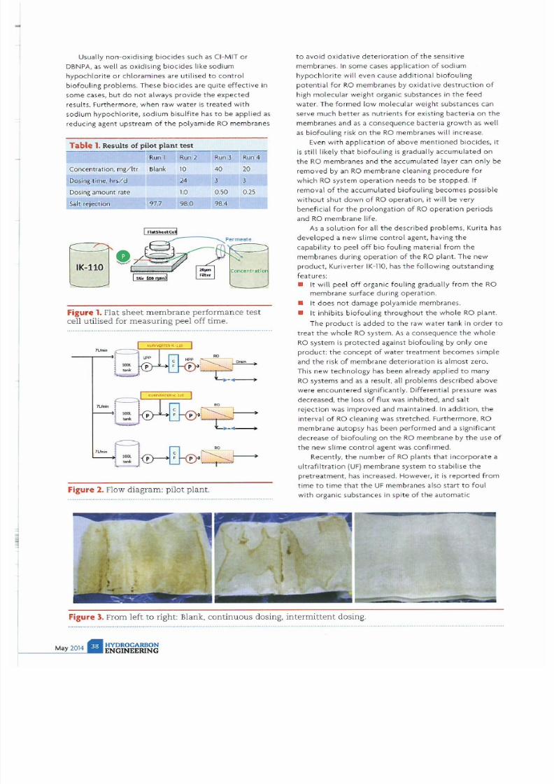
7/21/2019 Hydrocarbon Engineering Mayo 2014 Vol 19 05
http://slidepdf.com/reader/full/hydrocarbon-engineering-mayo-2014-vol-19-05 39/107
Usually non-ox idising biocides such as
CI
-MtT or
DBNPA ,
as
we
ll
as oxidising biocides like sodium
hypochlorite or chloramines
are
ut ilised
to
control
biofouling problems. These biocides are qUite effective in
some cases but do
not
always provide the expected
results
.
Furthermore
when raw water
is treated with
sodium hypochlorite, sodium bisulfite
has
to be applied as
reducing agent upstream of the polyamide RO membranes
Table
1 Re
sul ts
of
pilot plant test
Run 1 Run 2
Concentra tion mg/ltr Blank 10
O S
ing t ime
hrs/d
24
Dosing amount rate 1.0
Sa
lt rejection
7.
;.
8
;
0 _
Run
3
Run
4
40
J
0.50
98.4
20
J
0.
25
Figure
1
Flat sheet membrane performance test
cell utilised for
measuring
peel off time.
,.
Figure
2
Flow diagram: pilot plant.
to
avoid
oxidative
deterioration
of the sensitive
membranes. In some cases
application
o f sodium
hypochlorite
will
even cause additiona l biofouling
potential for RO membranes by oxidative dest ruction of
high molecular
weight
organic substances in t he feed
water. The formed low molecula r weight substances can
serve much better
as
nutrients
for existing bacteria on the
membranes and
as
a consequence bacteria growth
as
well
as biofoul ing risk on
the
RO membranes will increase.
Even with application of above
mentioned
bi
ocides
. it
is
st ill
likely that
biofouling
is
gradually accumula ted on
the RO
membranes and
the
accumulated layer can only be
removed by an
RO
membrane cleaning
procedure
for
which
RO system operation needs
to
be
stopped.
If
removal of the accumulated
biofouling
becomes possible
without
shut down of
RO
operation, it wi
ll
be very
beneficial
for
the
prolon
gation
of RO operation
pe
r
iods
and RO membrane life.
As
a so
lu t
ion for all the described problems , Kurita has
de
v
eloped
a
new
slime
control
agent, having
the
capabili t y
to
peel
off
bio
fouling
material from the
membranes during operation o f the RO plant. The new
product Kuriverte r -llO. has the following outstanding
features:
• It will peel off o rgani c
fouling
gradually from the RO
membrane
surface during
operation.
• It does
not
damage polyamide membranes.
• It
inhibits
biofouling throughout the whole RO
plant.
The product
is
added
to
the
raw water tank in order
to
treat t he whole RO system. As a consequence the
who
le
RO system is protected against biofouling by only
one
product: the concept
of
water
t r
eatment
becomes simple
and
the
risk
of
membrane
dete
riorat ion is almost zero.
This new technology has been already
applied
to
many
RO systems and
as
a result, all prob lems described above
were
encountered
Significant ly.
Differential
pressure was
decreased,
the
loss
of
flux was
inhibited
, and salt
rejection
was improved and maintained. In addition the
i
nterval of
RO cleani ng was st retched. Furthermore. RO
membrane autop
sy
has been per
formed
and a sign
if i
cant
dec rease
of
biofouling
on the RO
membrane by
the
use
of
the new
slime cont r
ol
agent was
confirmed.
Recently, the number of RO plants
that
incorporate a
ultrafiltration UF)
membrane system to stabilise the
pretreatment
has increased. However. it
is
reported
from
time
to
time that the UF
membranes also start to
foul
with
organiC substances in spite of the automatic
Figure 3. From left to right: Blank continuous dosing. intermittent dosing.

7/21/2019 Hydrocarbon Engineering Mayo 2014 Vol 19 05
http://slidepdf.com/reader/full/hydrocarbon-engineering-mayo-2014-vol-19-05 40/107
backwashing sequence. The new technology
is
also
applicable
to UF
membrane systems and it effectively
reduces biofouling for both.
UF
and RO membranes.
at the
same time.
In the following case study the application
of
the new
technology
to
an actual seawater reverse osmosis 5WRO)
sys
tem is
described.
As
a first step,
the most
suitable
application
method
was
evaluated by
laboratory and pilot
plant tests. After that the developed
concept
was applied
to one
line
of
a
three
lines SWRO plant. enabling a direct
comparison and
confir
mation
of the treatment
effect.
Laboratory
test
A flat
sheet
membrane performance tes t system, as shown
in
Figure
1,
was used as a fir
st
step of the
development. A
RO flat
sheet
membrane with slime
deposits
from
the
actual plant on its surface was placed into
the
performance test cell. The applied pressure was
set
closely
to
0
MPa
so that the
processing
water stayed
mainly
on
the
concentrate
side. Ultra pure water was
processed
to the
cell for 24 hrs as init ial treatment
to get
rid
of
existing loosen fouling material. After that. water
contain ing 200 mgllt
r
of
Kuriverter IK 110 was processed
through
the
cell and
the
concentrate
water was filtrated
through a 20 membrane filter
to
collect
the
peeled off
substance . The filters were exchanged
in
certain intervals.
The
amount of the
peeled
off
substance on
the
individual
filters was measured versus elapsed
time
and
the
surface
of the
20
J.lm
memb rane filters was investigated by a
stereoscopic microscope.
v'
Fast automatic
3D
piping model creation and calculation
of
acoustic pressure, flow rate, 3D forces at piping
JOints
and
bends
.,t
Automatic verificatIon and representation of pressure
pulsations according to
API618
and API 674 standards
v'
ACUSYS
is deeply tested and validated by comparison with
existing plants, theoretical solutions and commercial CFD
codes, showing much higher use efficiency.
SIMULATION OF PRESSURE WAVES
THROUGH PIPING
www.sate -italy.com
Santa Croce 664 la - 30135 Venezia Ita ly)
140
-+- WiUlOut
120
Cl
o ;
100
.0 :
W i t h I K 1 1 0
: E
~ ~ ~ ~
c
80
C
60
1
i
•
40
•
20
0
0 20 40 Ell
9J
100
peration time (day)
Figure
4 . Comparison of
permeate flow.
( CIP = cleaning in place)
Result
of the
investigation
One to two
hours
afte
r
the
injection
of the product
had
been star
ted.
'peeled
off
substance'
appeared
significantly
on
the
surface of the 20 ~ membrane filter. After these
two
hours the accumulation reduced with time and
afte
r
four hours it became almost zero. This tendency was
repeatedly observed and from
that fact
it was consider
ed
that
intermittent dosing with a dosing period
of
three
hours
will
be
the
most effective and economical
treatment
program. The
do
si
ng
interval
in the
actual plant
will
depend
on
the
raw water quality and
the
co
rresponding speed
of
slime formation on
the
membranes. The necessary dosing interval was determined
DESIGN OF PULSATION SUPPRESSION DEVICES
Prior
to modification
After
modification
CUSYS
Pressure pUlsation levels prior and after remedial actions
1-
I
I
F'tIo< '
I
.--
-
I-
TT
, -
I I
I. I
I
•
lL IL
l
.....,
.
,
.....,., _ .
....., . 'WCl
.....,
.. o.wc> C1 IWO' .....,C>
.....,0
....., 01 _ 0
Discharge configurationS ( .B.e 0 pumps. with ls l. 2nd
3rd
gssifler)
Consulting
Simulat ion
services
Software
for process plan
ts
and machines

7/21/2019 Hydrocarbon Engineering Mayo 2014 Vol 19 05
http://slidepdf.com/reader/full/hydrocarbon-engineering-mayo-2014-vol-19-05 41/107
350
.€
300
'
-+ - Without
S
i:>
E
150
=
U
100
E
50
1
0
0
40 00
100
peration time da y
Figure 5. Comparison of permeate conductivity.
( CIP
=
cleaning in place
0.4
& 0.3
::<
0.2
0.1
0.0
o
10
m
00 40 ro 00 00
100
operation
time
(days)
Figure 6. Changes in module differential pressure.
to
be
once
per
day for
the
worst
raw
water
quality and
it
can be
prolonged
for raw
water with
less biofouling
potential.
Pilot
plant test
before
application
A
pilot plant test
using
contaminated wastewater
as feed
was carried
out
to
confirm
the
results
of the
laboratory
tests.
Figure 2 shows
the
flow diagram
of the pilot
plant.
A 2.5 in. diameter SWRO membrane was used to optimise
ope rating condi ti on and the following ope ra tional
conditions
have
been
compared
:
• Blank.
• Continuous dosing.
10
mg/ltr.
•
Intermittent
high dosing, 40 mg/ltr, 3 hrs/d .
• Intermittent medium dosing. 20
mg/ltr,
3 hrs/d.
Results were obtained
after
27 days operation and are
summarised in Table
1.
Figure 3 shows the appearance of RO membrane
surface after testing.
It
is obvious that the
intermittent
dosing at higher concentration resulted in a better
cleaning performance compared
to 10
mg/l tr continuous
dosing. Moreover, the chemical consumption for
intermittent dosing was only half or one quarter of the
one
for
contin
uous dosing.
From the fac t that the
intermittent
dosing had shown
better resu l ts the application to the commercial SWRO
plant
was determined to be intermittent dosing of
HYDROCARBON
ENGINEERING
20
mg/ltr
for 3 hrs
/d.
This dosage of 20 mg/ltr complies
with the
dosing
lim
i t given by the
NSF
certification
for the
product.
Plant
conditions
before
the
trial
The plant performance had been already largely
deteriorated during 4 years of operation, which was
ma
inl y caused by high
pollution
of the seawater and an
insufficient
pretreatment
of t he polluted feed. Membrane
maint enance workload was very high with an average
cleaning frequency of once per month and additional
random membrane replacement.
Test
conditions
The app l ication was carr ied
out
in the following way by
an agreement with the
plant
owner.
•
Kuriverter
IK-110 is only
dosed to one
line with
20 mg/l tr during 3
hrs/d
while no dosing is applied
to
the other
2 lines
to
observe
the difference.
•
Other
chemicals such as PAC, NaClO,
sodium bisulfite
and
antiscalant
are
applied to
all
three
lines as
before.
• Observatory
period is
3 months.
As shown
in
the
following figures, the SWRO line
without
Kuri ta
treatment showed continuous
loss of
productivity . First pass permeate
flow
decreased from
87m
3
h r
down
to
30m
3
h r during
60 days since
the
sta rt
of the observation
with
the need of two
times chemical
cleaning during
that
period. On the other hand, the SWRO
Hne with Kuri
ta treatment
experienced a much
lower
decline
from 92m
3
h r to 60m /hr during 90
days
without
any
chemical cleaning
being necessary.
In
total, the cleaning frequency
was reduced
to
less
than one t hird. At the same time
sa
lt rejection and
permeate
water
quality
of the treated line were improving
while getting wo rse for the untreated line, which can be
clearly seen from the increasi ng permeate conductivity at
the later one . Obv iously, concentration polarisation due
to slime deposits was causing increasing permeate
conductivity on the non -treated line, while on the othe r
hand the new treatment could mitigate the slime
fo
r
mation
on the membranes and prevented the resu lting
pola r isa tion.
As shown in Figure 4 the blank line had to be cleaned
twice, on
the 35
th
and
58
th
day, caused by a drop in the
permeate flow. The line to which Kuriverter
IK
-110 was
added
could
be
operated continuously
w ithout cleaning
for
90
days
or more. As
an
evidence for
the above results,
the
app
l
icatio
n of
the
new sl ime
control
agent enabled a
permeate f low in the
treated
line that maintained
twice as
high as for
the
line without such treatment.
Within
t wo
months
after
t he start of operation, the
frequency
of
cleaning could be reduced to one third.
FolloWing
the
permeate
flow
trend, the re
cove
ry ratio
decreased from 40%
to
30%
within 3S
days
for
the
untreated line and was maintained at t he design value of
40%
for
the
One
wit
h
addition
of
the
new s
li
me
contro
l
agent . After the first cleaning in place (ClP) was
conducted
on the untreated line, the recovery rate was still
dec reas ing and finally dr
opped
to
18%
after 60 days of

7/21/2019 Hydrocarbon Engineering Mayo 2014 Vol 19 05
http://slidepdf.com/reader/full/hydrocarbon-engineering-mayo-2014-vol-19-05 42/107

7/21/2019 Hydrocarbon Engineering Mayo 2014 Vol 19 05
http://slidepdf.com/reader/full/hydrocarbon-engineering-mayo-2014-vol-19-05 43/107
operation. After the same period the treated line still
maintained a recovery rate of approximately 30 which was
further stabilised
over
another per iod of 30 days. In other
words, in spite of high load conditions the slime control agent
suppressed adhesion
of
slime and helped to maintain high
recovery and efficient operation of the
RO
system.
In case of biofouling material accumulating on the RO
membranes, the salt rejection is often decreased due to the
concentration polarisation effect on the membrane surface. This
is
resulting in lower permeate quality with higher conductivity. In
Figure 5 this effect can be dearly seen for the untreated
line
of
the SWRO plant. Although cleaning procedure to remove fouling
material had been applied
for
this line after
35
days of operation,
the conductiv ity of the permeate increased further from
150
- 200
mS/m
after 60 days of operation. On
the
other hand.
th
e permeate conductivity of the treated line decreased over the
same per iod and reached 40 mS/m after 60 days operation.
Figure 6 shows changes
in
differential pressure. Differential
pressure increased gradually
in
both lines and
no
remarkable
difference could
be observed in
differential
pressure during a 3S
day period. However. due
to
a decrease in permeate flow
clean i
ng
became necessary on
the
35
th
day
for the
untreated line.
Although
this cleaning obviously removed
fouling
material from
the
channels and caused recovery of
the differential
pressure to
the initial value, it
did
not recover
the
permeate
flow.
The
probable cause could be failure
to
remove materials adhering
closely to the membrane surface like microbes' metabolic
products, such as glycoproteins with several
ten
thousands
in
molecular
weight. In other wor
ds,
the cleaning proved
to
be
insufficient
•
Sulphur 2 14
The world's leading industry event
Gold Sponsors:
s o v a d i s
Outote'(
Et)
Ba
ye
r Technology Services
onclusion
The
new
treatment can be
considered
as an effect ive way to
suppress adhesion
of
microbes to
the
surface
of RO
membranes and
to
break away any adhering microbes and
the ir metabo li c products . Even in case of contaminated
feedwater and insufficient pretreatment systems the problem
solving
ability of
the
new product is coming along without
additional capita l investment cost. NSF
certification has
enabled Kuriverter IK-110 to be applied to drinking water
producing RO plants. One of the keys to success
is
to know
th
e
fluctuation
range of bio substance concentration and to
determine
the
application l imits. The
method
to find the
applicable
lim
it for various kinds of raw water
has
already
been established.
The benefits prov ided by applying Kuriverter IK -110 can be
evaluated by easily measurable factors:
• Cost reduction related
to
reduced chemical cleanings.
•
Less
cleaning chemicals.
• Reduced cleaning workload.
• Reduced membrane
replacement
cost.
• Increased
membrane
lifetime
due to less deterioration
by chemical cleaning.
• Energy cost saving.
• Lower
power
consumption
for
high pressure pumps ete.
• Reduced water
consumption
and wastewater generation.
• Less chemical cleanings.
• Higher recovery ratio.
• Higher stability and reliability of plant operation.
Keeping high
flux
and recovery
ratio.
• Maintaining high permeate quality.
i I
C . HEMTRAD£
'-'
p pump systems
ChemTrans
T
l
A
G
,ST EULER
i.
K H
Silver Sponsors:
H
AL
D OR TOPSD E rn
,
... -,_
.
.
.
HJn WEIR

7/21/2019 Hydrocarbon Engineering Mayo 2014 Vol 19 05
http://slidepdf.com/reader/full/hydrocarbon-engineering-mayo-2014-vol-19-05 44/107
WWW TOPSOE .COM
Maximize your hydrocracker
performance
A hydrocracker is one of the most profitable units in a refinery.
This is
ue
to volume swell and the ability to convert heavy
feedstocks into high value products such s naphtha, jet fuel,
diesel and UCO.
Improving your hydrocracker operation will significantly
optimize the
overall
cost-efficiency
of your
refinery.
Our comprehensive range of catalysts and technologies
enables
us
to provide you with a complete solution to ll your
hydrocracking requirements.
Combined with our pretreatment HyBRIM M catalysts, our
three hydrocracking catalyst series maximize your unit
performance and add value to your refinery operation.
For
mo
re information, please e-mail us at:
hydrocracking-1@topsoe . k
RESEARCH I TECHNOLOGY I CATALYSTS
O-sel - series -
maxim izes diesel yields
Blue series -
op
l
imizes cold
low IXOperties
Red seri
es -
maximizes hydrogenation
Activ ity
HALDOR
TOPSDE L j
CATAlYZING YOUR BUSINESS

7/21/2019 Hydrocarbon Engineering Mayo 2014 Vol 19 05
http://slidepdf.com/reader/full/hydrocarbon-engineering-mayo-2014-vol-19-05 45/107

7/21/2019 Hydrocarbon Engineering Mayo 2014 Vol 19 05
http://slidepdf.com/reader/full/hydrocarbon-engineering-mayo-2014-vol-19-05 46/107

7/21/2019 Hydrocarbon Engineering Mayo 2014 Vol 19 05
http://slidepdf.com/reader/full/hydrocarbon-engineering-mayo-2014-vol-19-05 47/107
Relatively
large
stack
diameter
Figure
1
Typical air flare configuration
technology specifically targeted
to
eliminate smoke in
an
efficient, economical manner in areas
without
access to steam
and without the need for a new flare stack. The new HPAAS
technology utilises super sonic air injection in a manner
that
can
be easily adapted to retrofit and upgrade outdated smoking
technologies. The appl ication
of HPAAS is
proven
to
bring
exceptional value to the user in both operational and monetary
terms
Drivers for change
Operational standards throughout
the
petroleum industry are
continuously evaluated and updated in favour
of
practices that
relieve environmental impacts. This
is true of
flaring and
is
especially
true
in
the
case
of
smoking flares. The impetus for
change
often
comes in
the
form
of
environmental regulations,
but
it can also stem
rom
monetary drivers
or public
perception.
Visible
for
kilometers and omnipresent, elevat ed flares are a
billboard
that
cannot be turned
off
Due to this high visibility,
the
fire and any smoke emitted from flares attract
the
acute
attention
and concern
of
all parties
who
wish
to
mitigate
inefficiencies and emissions in
the
industry. Whether
or not the
level of attention given to flares is justifiable.
the
flare is
becoming a lightning rod driving change in flaring technology.
HYDROC RBON
ENGINEERING
This change
is
coming qUickly and steadily to
the Middle
East.
While lim
itations
on
emissions and smoking flares
legislated around
the world
may
not
apply to all locations in
this region,
other
influencers may have a similar, nearer
term
effect. International and financial institutions have
formed
coalitions to incentivise
the
operational changes. Some
of the
most
influential companies in
the
industry have enacted internal
protocols
that
exceed
government or
international standards to
demonstrate their
commitment
to environmental concerns.
It is
conceivable
that
additional operators in
the
Middle East
will
necessarily revise flare design and operation protocols in
the
near term wh ether driven by regulat ion, incenti
ve,
or their
own
initiative.
PreViously, the second revision of The Royal Commission
for Environmental Regu
la
tions RCERP issued operational
protocols
and standards
for the
Jubail and Yanbu industrial
areas to specifically address emissions and air quality. The
initiative requires normal flare
operation
to be
completely
free
from
smoke emissions and Significantly
re
stricts
the allowed
frequency and length
of
permitted
process upsets. In these
industrial areas, dozens
upon
dozens
of
flare tips are in constant
service. When a regulation such
as RCER
is enacted,
the
conversion
of
existing non-smokeless flares becomes a
priority
for the
operators.
In the common
case where a flare
is
already
in existence, retrofitting a smokeless technology in a cost and
utility
efficient manner can be a challenging endeavor. Failure
to
do so, however.
ca
n result in
penalty
by fines. These range in
magnitude from minor charges
of
USS 1000 to one
time
penalties in excess
of
USS 100 000.
9
The
dr
ivers for change do not have to
come
from wi
thin
a
country s borders. An international initiative by
the World
Bank
seeks to minimise
the
loss
of
natural resources and reduce
the
environmental and
dimatological impact of
flaring and venting
associated with
the
production
of
crude oil.
2
The Global
Initiative
on
Natural
Gas
Flaring Reduction GGFR) was formed
with
the purpose of changing public policy via monetary
incentives within prodUCing countri es
with
active flaring
practices. The combination of monetary incentives and
aforementioned legislative penalties are targeted to bring about
the desired change in operational procedures and parameters.
8
Part of the initiati ve recognises
that
the formation of smoke
when flaring represents incompleteness in combustion. and as a
result the
environmental i
mpact of
a smoky flare
is
greater than
that of
a smokeless
one
.
While
varying
from
country to country.
the
result
of
the
GGFR initiatives
could
lead
to more st
ringent
sm
okeless requirements. These procedural changes become
complex and expensive to
retrofit
to existing equipment.
Either as a result
of the afo
r
ementioned
external influences
or
by their
own
internal prerogatives. company operational
procedures
often
require
improved
smokeless
perfo
rmance
for
flares. To be congruent w i
th the
RCER and
other
internal
initiatives, Saudi Aramco
has
publi shed stri ngent flare operation
protocols in
their
engineering standards specifications
SAES-A-102.
s
Accord ing to
th
is standard. all flares
with
a
throughput
of up to 1
million
ft2/d are requ ired to be smokeless
for
all normal operations. Flares exceeding
that
flow rate are
required
to
have a flare gas recovery system installed
to
mitigate flaring almost entirely. The enactment of this
specification
has
massive impl ications when applied to the
numerous flares already in existence
without the
necessary

7/21/2019 Hydrocarbon Engineering Mayo 2014 Vol 19 05
http://slidepdf.com/reader/full/hydrocarbon-engineering-mayo-2014-vol-19-05 48/107
ho
monitors
the
most reciprocating compressors?
When you look at the numbers, i t all adds up to PRO NOST Systems:
Largest installed base o online diagnostic systems
on
reciprocating compressors
The world s
top
refiners and HPI producers trust PROGNOSi systems
Over 20 years
o
experience in monitoring reciprocating machinery
PRO NOST has one focus - reciprocating machinery.
Our dedication ensures that your system remains best-in-class.
[email protected] www.prognost.com
I.
:llIhI
PROGNOST
telligence on uty

7/21/2019 Hydrocarbon Engineering Mayo 2014 Vol 19 05
http://slidepdf.com/reader/full/hydrocarbon-engineering-mayo-2014-vol-19-05 49/107
Figure 2. The HPAAS initial design was developed
using computational fluid dynamics CFO) analysis
nd
field testing.
utilities installed to achieve smokeless combustion. When an
in
ternat
ional company im
plements
a similar in itiative, the
impact is fe lt on operations in multiple countries.
All three drivers of change, regulatory, incentivised, and
internal apply
to most of the
Middle East including
the
countries of Egypt. Iraq, Kingdom of Saudi Arabia, Kuwait. Oman,
Pakistan, and Qatar. Even
if
such
operational
requirements are
not
affecting a particular
si
te yet. it
is
a reasonable assumption
th t they
will
be
in the
nea r future.
The initiatives to reduce smoking flares are greatly
impacting the Middle East; however, nowhere in the world is it
more challenging
to
accommodate inc reasing smokeless flaring
capacities. Steam injection is used worldwide for the smoke
suppression
of
heavy hydrocarbon flares.
In
these applications.
steam is injected as a transport media to inspirate and mix air
at
the insipient region of the
combustion
zone. However, since
water
is a premium commod ity in the
Middle Ea
st. a need exists
for
a suitable alternative to steam assisted flaring. The
mechanical injection
of
air by means
of
fan
or
pressure
blower
is well known and proven smokeless
technology
in
the
industry.
Though typical air assisted flares do not requi re water, a scarce
resource.
the
initial capital
cost of the equipment
is comparably
quite high since
the
configuration normally requires axial flow
of
the air and gas.
i.e.
a stack within a stack. Th is makes retrofit
applications nearly impossible; upgrading a smoking flare to air
assisted often requires an entirely new flare system
with
an
installed
weight nominally
three to
four
times greater than the
unassisted alternative.
M any valid
technolog
ical options for smokeless flaring exist
for capital projects, but what kind of financial commitment will
it take
to
upgrade the hundreds upon hundreds of flares in
existence? Until HPAAS was developed. the financial burden of
meeting
the revised operational standards was perceived
as too
steep to
enact wholly.
HPAAS technology
The basis of
the
HPAAS technology is
to transport
the injection
media in the
most
compact means and inspirate air as
efficiently
as possible. Following a
brief
discussion
of
the configuration and
requi rements
of
a typical low pressure air assisted smokeless
flare system, this art icle will examine the differences in a HPAAS
configuration. For low pressure systems typical in
the
industry.
vast amounts of air are utilised to
prevent
smoking in the flare.
Airflow
rates ranging fr
om
30 -
SO
of
the stoichiomet
ric air
are required for complete combustion and must be
mechanically induced. Due to the
la
rge air flow required in a
standard configuration, the diameter of the air delivery
HYDROCARBON
ENGINEERING
structu re is larger than the gas riser itself. This is deSigned
to
reduce
the
velocity within the stack. minimise the pressure drop
within the system and ultimately conserve the capital cost of
the
blower by minimising its power requirements (Figure 1 .
By
utilising much higher pressure air than typical deSigns,
HPAAS flare tips ut i
l ise air in a manner comparable
to
steam
injection tips. Instead
of
injecting
most of the
air required
for
smokeless flaring. highly kinetic
jet
streams
of
air aspirate
ambient air
into the
combustion zone. This configuration is
highly
efficient
in
the
volume
of
air used;
less
than one tenth
of
the
airflow is required compared to
low
pressure technologies.
Additionally, since this minute air
volume
is injected at high
pressures. the delivery of air occurs in a much smaller pipe
often of only 2
or
3
in.
nominal diameter.
1
The smaller pipe
generates several cost savings
to
the user; the large diameter air
ducting stack is eliminated
completely
the
weight
and forces o
the stack are minimal and therefore structural considerations
such
as
civil wo rk or guy wires are minimised.
The
patented
design and l
ayout of the HPAAS
injection tips
are
the
crucial elements
for
delivering
the
benefits discussed.
For the first
time
in the industry.
proprietary
supersonic air
injec
tion
nozzles
were
developed
to
maximise
the efficiency
of
the
air injected
through
the system. The
jet of
air produced by
the nozzle creates a turbu
lent
wake, inducing ambient air
into
the combustion zone. In this manner. the effect of the relatively
tiny flow
of
compressed air is
multiplied
so that a significant
portion
of
the air required
for complete
combustion is available
at the flare tip exit prior to the formation smoke. In conjunc tion
with
using these advanced air noules the correct placement
and mixing set up by these t ips is paramount to
the
success
of
the
design.
When the combination of
induced and injected air
reach
the
flare
tip
exit,
the
veloCity, angle
of
approach. and
volume have been
optimised for
interaction with the gases and
shaping
of the
flame. The nozzle placement is refined to ensure
the
induced air is also fully mixed with the waste gas stream and
complete smokeless combustion occurs (Figure 3).
A specialised windshield is integral to the induction of
ambient
air. By enhancing the upward draft around the
perimeter of the flare tip. the momentum of the air wi
th
in the
windshield overcomes the tendency for flame pull down on the
downwind side of the flare. In effect. it shepherds the flame in
an u
pward
column and prevents the impingement on
the
flare
tip barrel common
to uti
l ity flares.
The initial design was conceived by Saudi Aramco
through
advanced computational
flu
id dynamics (CFD) analyses (Figure
2)
and
field
testing in select southern area
gas
oil separation
plant (GOSP) locations.
1
Finalisation of
the
nozzle and
windshield layout occurred through extensive
full
scale testing
at Zeeco s Research and
Development
Facility in Broken Arrow.
Oklahoma. under the
observation of Saudi Aramco personnel.
The
combination of
live testing validation and
CFD modelling
rendered a proprietary
layout
that optimises the overall
performance, reliabil ity, and longevity of the flare system.
The supply
of
air
for
these systems is most often generated
by an air compressor. This is typically welcomed by the user
since it is a familiar
technology with
competitive selection
opportunities
between
many vendors. In
tight
turnaround
situat ions, temporary air capacity is achievable through portable
natural gas
or
diesel driven compressors. Compressors are eaSily
run in pa rallel configurations for increased
online
performance,
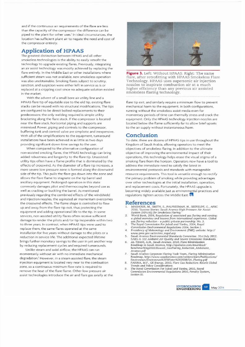
7/21/2019 Hydrocarbon Engineering Mayo 2014 Vol 19 05
http://slidepdf.com/reader/full/hydrocarbon-engineering-mayo-2014-vol-19-05 50/107
and
if
the continuous air requirements
of
the flare are less
than the capacity
of
the compressor the difference can be
piped to the plant for other uses. In ideal circumstances,
the
loca
tion
has sufficient plant air to negate the need and cost
of
the compressor entirely.
Application
of
HPAAS
The greatest distinction between HPAAS and all other
smokeless technologies
is
the ability
to
easily
retrofit
the
technology
to
upgrade existing flares. Previously, integrating
an air assist technology was mostly achieved by replacing
the
flare entirely.
In
the
Middle
East or
other
installations where
sufficient steam
was
not available, new smokeless operation
was also unobtainable. Smoking flares subject to scrutiny,
sanction, and suspicion were either
left
in
service as
is
or
replaced
at
a crippling cost since no adequate solution existed
in the market.
With
the advent of a small bore air util
ity
line and a
HPAAS
flare
tip
of
equitable size
to
the
old
tip, existing flare
stacks can
be
reused
with
no structural modifications. The t i
ps
are configured
to
be
direct bolted
replacements
to
their
predecessors; the
only
welding required
is
simple
utility
bracketing along the flare stack. If
the
compressor is located
near the flare stack, horizontal piping and supports are
minimised. Power, piping and con tro ls
to
the compressor,
buffering tank and
control
valve are simplistic and inexpensive.
With all
of
the simplifications to the equipment, turnaround
installations have been achieved in as little as
two
days
pro
viding significant
down time
savings
to
the
user.
When compared
to the
alternative
co
nfiguration
of
non-assisted smoking flares, the
HPAAS
technology can bring
added robustness and longevity to the flare tip. Unassisted
utility tips
often
have a flame
profile that is
dominated by the
effects
of
crosswind.
As
the diameter
of
a flare
tip
increases, a
more severe low pressure zone is formed along the downwind
side
of
the tip. Th is pulls the flare gas down
into
the zone and
allows the flare flame
to
stagnate on the tip barrel and
ancillary equipment. Prolonged operation in this state
commonly damages pilot and thermocouples beyond use as
well as cracking or buckling
the
barrel.
As
mentioned
previously regarding the combined effects
of
the windshield
and injection nozzles,
the
aspirated air momentum overcomes
the crosswind effects. The flame shape
is
controlled
to
flow
up
and away from the flare tip exit, thus protecting the
equipment and adding operational life
to
the tip.
In
some
services, non-assisted
utility
flares
often
receive sufficient
damage to render the pilots and or tip inoperable with in two
to three years.
In
contrast, when HPAAS tips were used to
replace them.
the
same flares operated at the
same
installation for five years without damage to the pilots or a
reduction in service life. The additional expected l ifetime
brings further monetary savings to
the
user in yet another way
by
redUCing
replacement cycles and required turnarounds.
Unlike steam and axial airflow, the HPAAS can
run
momentarily
without
air
with
no
immediate mechanical
degradation.
1
However, in a steam assisted flare, the steam
injection equipment
is
located very near
to
the combustion
zone, so a continuous minimum flow rate is required to
remove the heat
of
the flare flame.
Other
low pressure air
assist technologies introduce the air and flare gas aXially at the
Figure 3. Left: Without
HPAAS.
Right: The same
flare, after retrofitting with HPAAS Smokeless Flare
Technology. HPAAS uses supersonic air injection
nozzles to inspirate combustion air
at
a
much
higher efficiency than any previous air assisted
smokeless flaring technology.
flare
tip
exit, and similarly require a minimum
flow
to
prevent
mechanical harm
to
the equipment.
In both
configurations,
running
without
the smokeless assist media even
for
momentary periods of time can thermally stress and crack the
equipment. Only the HPAAS technology injection nozzles are
located
below
the flame sufficiently far
to allow brief
upsets
to
the air supply
without
instantaneous harm.
Conclusion
To date, there are dozens
of
HPAAS tips in use
throughout
the
Kingdom of Saud i Arabia, allOWing operators to meet the
objectives of smokeless flaring. In addition to the ultimate
objective
of
improving the environmental impact
of
their
operations, this technology helps erase the visual stigma
of
a
smoking flare
from
the horizon. Operators now have a tool
to
address the immediate need to satisfy the latest
in
environmental protocols and standards
with
manageable
resource requirements. This
tool is
versatile enough
to
rectify
the primary problem
of
smoking while proViding advantages
over other technologies at the initial installation, operation,
and replacement costs. Fortunately, the HPAAS upgrade is
becoming widely available just as environmental practices and
regulations tighten across the
Middle
East.
I"
References
1. MASHOUR, M., SMITH, S., PALFREEMAN, N.,
SEEFELDT,
G., AFRC
2010, 'Success Stories: Saudi
Aramco
High Pressure Air Assist
System
HPAAS) for
Smokeless
Flaring.
2. World Bank, 2004, Regulation of associated gas flaring and venting:
a
global
overview and
lessons from international
experience. Global
gas flaring reduction - a public-private partnership: No. 3.
3. The Royal Commission For
Jubail
and
Yanbu
2004, Royal
Commission Environmental Regulations 2004, Section
I.
4. Presidency
o
Meteorology
and
Environment (PME) website: http:
www.pme.gov.sa/en/envJegul.asp
5.
Saudi Aramco Environmental
Standards
Committee.
31st
July
2012.
SAES-A·I02 Ambient
Air Quality and
Source Emissions
Standards.
6.
AL-Tl]ANI, A.H.,
Saudi Aramco, 2010, Flare
Minimization
Roadmap in Saudi Aramco, http://spatia1co.com/download
benchmarking2010/KuwaiCGasFlaring_
Reduction
_Abdulaziz_
Aramco.pdf
7.
Saudi Aramco Corporate
Flaring
Task Team,
Flaring Minimization
Roadmap,
http://www.saudiaramco.com/contenUdam/Publications/
EnvironewslEnvironews%20Winter%202008/SA]laring.pdf
8. FARINA, M.F .,
GE
Energy, 2010,
Flare
Gas Reduction:
Recent Global
Trends and
Policy Considerations.
9.
The
Royal
Commission
For
Jubail
and Yanbu 2010 Royal
Commission
Environmental
Regulations
2010 Penalty
System,
Section
Ill.
HYDROC RBON

7/21/2019 Hydrocarbon Engineering Mayo 2014 Vol 19 05
http://slidepdf.com/reader/full/hydrocarbon-engineering-mayo-2014-vol-19-05 51/107
ollow
_ @Energy_Global
onne t
Hydrocarbon
Engineering
HYDROC RBON
N IN RING
• •
JO n
fm
Hydrocarbon
Engineering
like
Energy Global

7/21/2019 Hydrocarbon Engineering Mayo 2014 Vol 19 05
http://slidepdf.com/reader/full/hydrocarbon-engineering-mayo-2014-vol-19-05 52/107
Patrick Gripka, Opinder Bhan, Wes Whitecotton
and James Esteban, Criterion Catalysts and
Technologies, USA, take a look
at
Tier 3
capital
avoidance wi
th
the help of catalyst solutions.
T
e
US
Environmental Protect ion Agency
EPA)
has fina lised new regulations designed
to
reduce air
pollution from
passenger cars and
trucks. The regulations commonly referred
to
as Tier 3 set new vehicle emisSion standards and lower
the
annual average sulfur
content of
gasoline from
30 to
10 ppm .
Additionally. the regulations maintain the
current 8 ppm refinery gate and 95 ppm downstream
caps. The
implementation
date
is
January pt, 2017 .
These Tier 3 gasoline sulfur specifications are simi lar
to
levels already being achieved in California, Europe,
Japan, South Korea and several
other
countr
ies
.
Implications
of
Tier 3
on
refinery processing
Th e gasoline pool
is composed of
gasoline bOiling
range
hydrocarbons
from several sou rces
in the
refinery. Typical gasoline pool blending components
include butanes.
ethano
l light stra
ight
run naphtha
iso
merate
r
eformate
alkylate fluid cata lytic
cracker
Fee)
gasoline
and
hydrocracker gasoline.
In
addition purchased blending components may also
HYDROC RBON

7/21/2019 Hydrocarbon Engineering Mayo 2014 Vol 19 05
http://slidepdf.com/reader/full/hydrocarbon-engineering-mayo-2014-vol-19-05 53/107
350
300
-so
10
3
• Max Content
Refinery Gate
Max
• Cor
porate
Aver
ag
e
• Annual Average
Figure 1. US gasoline sulfu r requirements.
'
.
. . . 0
no
•
''
.
,.
r' .... o . 'Mo r' '''' ... ' .
Mo
p ,,, .... ' '''''0 I'I' ·H'\
l ' ' ' ~
. RI/AIIOS . RVAtlDN ~ C o m O < > I
Figure 2. Criterion FCC PT continued catalyst
evolution.
.
be present. Most
of
t hese components are very low in
sulfur (typically <1 ppm) except for the Fee gasoline.
Not
only does the Fee gaso line have th e highest sulfur
content, but it is typically also the large
st
volume
compon
ent
o f t he gasoline pooL
As
a resu lt,
e
gasoline
sulfur will have to be reduced to 20 • 30 ppm in order
for
a typical refinery
to
meet the
proposed
Tier 3 regulations.
At present
few, if any , refineries are
able to blend
sign ificant
amounts
of
Fee
gasoline into the gasoline pool
without
employing hydrotreating t o reduce sui fur.
Options refiners are currently
utilising to
meet cu rrent
Tier 2 regulations includ e:
•
Pretreatment
of Fee feed:
Pretreatment
reduces the
sulfur of the
Fec
feed, which in
turn
lowers the sulfur
of the FCC products including FeC gasoline.
• Post
treat FCC
gasoline: Post treatment directly
reduces FCC gasoline sul fur.
• Combination of FCC feed
pretreatment
and Fee
gasoline
post treatment.
Current
unit
constraints and relative economics of the
available options will
determine
the
technology
selecti o n
for
meeting Tier 3 regulations.
Catalyst developments in FCC
pretreatment
To meet
the
demand for improved catalysts in
FCC
pretreatment se rvice
to meet
Tier 2 regulations, Criterion
Catalysts
&
Techno
lo
gies l.P. Criterion) developed and
commercialised the
ASCENT
' family of catalysts
with
DN-3551 NiMo
and OC -
2551
CoMo. Criterion
has
continued
to invest heavily in R&O and has developed and
commercialised the CENT
ERA
fam ily of catalysts
for
Fee
pretreatment:
ON-3651
NiMo and OC-2650 CoMo.
Figure 2 highlights the con tinuing evolution of FCe
pretreatment NiMo catalyst development by Criterio
n.
Refiners were able to take advantage of the increased
activity of DN-3551 to meet Tier 2 regulations and st ill
achieve long catalyst l ife; simil arly, the increased act iv ity of
the recent ly commercialised CENTERA DN-3651 will assist
refiners in meeting the proposed Tier 3 regulations.
Criterion's newest CoMo FCC pretreatment catalyst,
CENTERA
DC-2650, is
often
used in
conjunction with
CENTERA DN
-3651,
especially in
low
er pressure units
to
optimise
hydrodesulfurisation (H05) and
hydrodenitrification
(HDN) performance
These new
catalytic
developments
allow
cur
rent
Fec
pretreatment
units
to
produce lower product su lfur at the
same operating
conditions
and minimise the investments
required
to
meet Tier 3 requirements.
Capital avoidance
Many refiners have invested heavily in robust Fec
pretrcutmcnt units
to meet
Tier 2 regulations
as well
as
MACT standards for FCC emissions. Leveraging advanced
catalyst technologies
with
existing assets can, in many
cases, provide attractive so lutions
to
both minimise
capital investment
as
well
as
improve re f ine ry
profitability. The FCC pretreatment unit plays a
critical
role in optimis ing FCC performance. Removal of sulfur
from
FCC
feed improves
FCC
product quality while the
removal of nitrogen and contaminant metals improves
FCC ca ta l ys t performance and reduces catalyst usage.
Additionally,
hydrogenation of the Fec feed improves
conversion by reduc ing the
concentration
of
polynu
c lear
aromatic species. In many applicat ions, drop in
catalyt
ic
solut ions
for FCC
pretreatment units can achieve
higher
severity wi th l it t le to no capital investment and min imal
change in
cycle
life.
The re are several key
factors to consider when
evaluating
FCC pret reatme
nt
un i
ts for higher severity
operations:
• Hyd rogen availability including recycle gas capacity to
account for add i
tiona
l consumption.
• Heat balance fo r ope ra tion at higher rea
ct o
r
temperatures.
• Cycle life targets.
• Current and
future
capacity targets
as
it relates to
reactor space velocity.
• Operating constraints such as
fractionation
limitations.
For a medium pressure
unit
with average feed
properties and a
typical 36
month cycle life cu rrently
7/21/2019 Hydrocarbon Engineering Mayo 2014 Vol 19 05
http://slidepdf.com/reader/full/hydrocarbon-engineering-mayo-2014-vol-19-05 54/107
IIlndustrial and academic research
the best
of
both worlds.
Meet homas
Weber:
Kn owledge Seeker, ylng it
Fo
rword
You might say that Thomas
Weber
a lead scientist at CRITERION, is a know-it-all . Not because
he s
proud , but because he sincerely wants to
know
it all. Ta satisfy his insatiable drive to understand
the whys behind every reaction ,
Weber
immersed himself in
academia. While
eorning his post
doctorate, a professor
land
former Shell scientist) exposed Thomas to
the world of
catalyst
reseorch, leading him to a coreer with
CRITE
R
ION.
Today, when Thomas isn t
in
the
labo
ratory,
he s likely teaching chemistry at one
of
the top universities
in
catalysis
in the
Netherlands.
like
his
mentor before, Thomas
is
developing the next generation of catalysts - and next generation
of scientists
os well.
Leading minds Advanc t •
5
B r . ~ ~ L Q ~
www
.CRITERIONCatal
ys t
s.c
am

7/21/2019 Hydrocarbon Engineering Mayo 2014 Vol 19 05
http://slidepdf.com/reader/full/hydrocarbon-engineering-mayo-2014-vol-19-05 55/107
Fe
e Cr ack ing 0 H
Figure
3.
Impact
of untreated
aromatic molecule on
Fee
products.
removed. The
number
of
unsaturated
r ings
adjacent to each other
is
critical in
determining the boiling range of the final
Fee product. Molecules with one ring end
up in
the
Fee naphtha cu t, 2
and
some
3 ring
molecules go
to
the Leo
cut
whi
le most 3
ring and greater mo lecu les are either
fou
nd
in
the
HCO and cla rifi ed oil st ream s o r
deposit as coke. Saturation of aromatics
results in higher value products
and
greater
Ben;tothiophene i n
gaeol
i
ne boiling ,ang .
conve rsion in
the
Fee. Saturat ion of
aromati
c rings
sta
rts
from
the
cent
re
of the
molecule wi
th
a decrease in relative
rea
ction
rat e as p
olynuclear aromatics are
hyd
rogenated
.
The cr
itical o
perating paramete
rs
that
influence these
reaction
rates are hydrogen
partial pressure and operating temperature.
In order
to
maximise aromati
cs
saturation
Figure 4. Impact
of
low severity aromat ic treatment on
Fee
products.
for
a given uni t,
it is
important
to
maximise
or
sulfides are nOI
in
gasoli
ne
boiting range
hydrogen purity and hydrogen avai labili t y to
optimise hydrogen partial pressure,
part icularly at t he reactor outlet. In addition
to maximising hydrogen part ial pressure,
operat ing temperatures must be increased
to maximise
sa
turation. Howeve r, saturation
of aromatics is equilibrium l imited at
constant hydrogen part ial pressure so
there
is an o
pt
imum temperature range for
igure 5. Im pact of h igher severity aromatic treatment on
Fee
products.
maximum saturat ion. This optimum
temperature range is often referred to as t he
kinetic
region
or
the
aromat
ics saturat
ion
plateau. Operating in the kinetic region
prOVides the best quality feed for the Fee.
... ............... ........... ...
C, ,
r'
,
,
•
C,H, ©
Ui>
CC Cracking
•
0 S
c,H,
CA
©
cS
.
S
AND f OA
C . H
Hp
n
CH
\i,R,
CH
Hfi
R
•
CH
Hfi- R
CH,
When evaluating an increase in severity of a
Fec pretreatment unit, there
is
typically a
synergy between the additional temperat ure
required and ma ximum aromat ics saturat ion
operating mode. The elevated desulfurisation
severity drives the unit closer
to
maximum
aromatics saturation mode, which re sul ts in
Figure 6. Impact
of
basic nitrogen inhibition on
Fee
products.
improved yields
in
the FCC product
sla
te.
Additional
ly,
the elevated desulfurisation
severity early in the cycle capitalises on the
maximum aromatic
sa
turation activi ty of theroducing 1000 ppm product sulfur, the more severe Fec
pretreatment opera
ti on
t o produce FCC gaso line su
lf
ur in
the 20 - 30 ppm range requires FCC pretreatment prod u
ct
s
ulfur to
be in the
300
ppm range and cycle l ife is
still
more than 24 months
when
us ing CENTERA ca
talyst.
In
addition, the product nitrogen
is
reduced significan
tly
and
hydrogen consumption, FCC pretreatment vo lume gain
and Fec conversion are increased.
The improvemen t s in Fee performance and y ields
from
higher severity operat ion of the Fec pretreatment
unit are linked to the inc reased saturation of po lynuclear
aromatics. The s
aturation
of aromatic rings in these
comp
lex
mole
cules
determines
both
the
product
distribution and the relative sulfur
dist
r ibution in the
Fee
products. In the FCC, aroma tic r ings do
not
crack
whil
e
functional
groups attached to the aromatic rings can be
catalyst sys tem throughout the cycle which maximises overall
yields.
Increased aromatic
sa
turation has an impact on the
distribution of the sulfur containing aromatic molecules in
Fce products. The
following
discussion illustrates the impact
of FCC pretreatment seve rity on a typical polynuclear
aromatic species and the impacts on product sulfur
distribution.
Untreated feed (no FCC
pretreatment
For
an
untreated aromatic molecule, the
FCC
simply removes
the
functional group chains attached to the compound and
leaves the majority of the molecule unconverted, resulting in
higher coke and
or
cycle oil yield. This results in higher sulfur

7/21/2019 Hydrocarbon Engineering Mayo 2014 Vol 19 05
http://slidepdf.com/reader/full/hydrocarbon-engineering-mayo-2014-vol-19-05 56/107
in
the unconverted cycle oils
or
higher
sax
in
the
fiue
gas
after
coke is burned off the catalyst. There is a low probabil ity
of
seconda ry thiophene cracking
in
the Fee. thus the suI fur
in
this molecule ends up in the cycle oil
or
coke (Figure 3).
Low
severity
F pretreatment
When
the
same molecule is treated but in a low severity
operation
, the resulting aromatic
saturation
result is an
increase in gasoline yield. But because
the sulfur atom
remains i
ntegrated with
the
aromatic benzothi
ophene,
the
probability
of secondary cracking is low and it remains in
the gasoline boiling range (Figure 4).
Higher severity F
pretrea tmen t
Increased
aromatic
saturat ion by increasing severity in
the FCC pretreatment
unit conve rts
the polynuclear
aromatic
(PNA) to a single ring compound. Secondary
cracking of the thiophene yields H1S, which removes the
sulfur from the gasoline boiling range (Figure 5).
This secondary
thiophen
e cracking in
the
FCC is
inh ibited by the basic nitrogen
in
the
Fce
feed and, in the
presence of basic nitrogen. the inhibition decreases the
amount of sulfur removed from the gasoline fraction
(Figure 6).
The higher severity FeC pretreatment
operation
thus
provides additional advantages by increasing the nitrogen
and basic nitrogen removal from FCC feed. This impacts FCC
cracking reactions and influences
the distribution of
sui fur
in
the
FCC products. Thus, improved nitrogen removal also
leads
to
a reduction in gasoline sulfur.
In conclusion, the increased HDS achieved by
increased FCC
pretreatment
severity along
with
the higher
saturation and
denitrification
are critical in reducing FCC
gasoline sulfur while still achieving reasonable cycle life.
Applying best available
catalyst technologies
opens
the
door to
improved
product
quality
and maximum
profitability.
Several US ref iners are already using Criterion s
industry leading catalysts
to increase severity and are
capturing
the yield improvements
while also
producing
low sulfur FCC gasoline streams that are suitable for
blending to Tier 3
specifications.
With
the
increased
severity, the diesel side stream off the FCC pretreatment
unit
has
, in several cases, been
of
ultra low
sulfur
diesel
(ULSD) quality, thereby
further
improving the economics.
atalyst developments in F
post
treatment
Likewise
Criterion
has
continued
R D
development of
FCC gasoline post treatment catalysts with focus on
maximising
desulfurisation
activity and
selectivity
w ith
minimal
olefin saturation. Criterion
curren
tl y
produces
a
Generation FeC post treatment catalyst that is
employed in
Fee
gasoline
post
treatment with a new
catalyst
in
the development
stage. The new catalyst is
designed for maximum sulfur
reduction
while minimising
octane loss.
The
ke
y challenge has been to develop catalyst
nanostructures that selectively maximise desulfurisation
sites, whi le minimising active sites associated w
ith
hydrogenation
of
olefins.
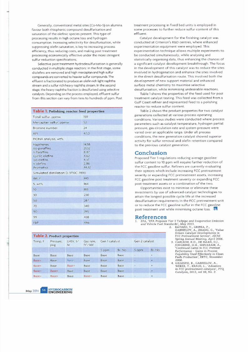
7/21/2019 Hydrocarbon Engineering Mayo 2014 Vol 19 05
http://slidepdf.com/reader/full/hydrocarbon-engineering-mayo-2014-vol-19-05 57/107
Generally. conventional metal sites (Co-Mo-
S)
on alumina
favour
bo t
h thiophenic compound desulfurisation and
satur
at
i
on
of
the
olefinic species present. This
type
of
process
in
g results
in
high octane loss and hydrogen
consumption. Increasing selectivity for desulfurisation, whi
le
suppressing olefin saturation, is key to increasing process
effiCiency, thus reducing cos ts, and making post
treatment
processing economically effective under the more stringent
suifur reduction specifications.
Select
ive
post treatment hydrodesulfur
isa
ti
on is
generally
co
ndu
cted in
multiple stage reactors:
in
the first stage. some
diolefins are removed and high mercaptan and
high sui fur
compounds are converted
to
heavier
sulfur
compounds. The
effluent
is
fractionated
to
produce an olefin
rich
light naphtha
stream and a sulfur
rich
heavy naphtha stream.
In
the second
stage. the heavy naphtha fraction
is
desulfurised
using
selective
catalysts. Depending on the process employed, effluent
sui fur
from this section can vary
from tens to
hundreds
of
ppm. Post
Table 1. Polishing reactor feed properties
Total sulfur. ppmw
159
Mercaptan sul fur, ppmw 52
Bromine number
24
AP
I
47,0
PIONA analysis, wt
Napthenes
14.55
I
so
paraffins
2U2
n
Pa
raffins
8.47
Cyclic olefins
4,62
ISO oleffns
4,37
n o l
ef
i
ns
2,
86
Aromatics
44.12
Simulated d ist illation D-3710C-7890
IBP, F
5,
wt
10
30
50
70
90
99
FBP
Table 2. Product properties
Temp , F
Base
s....
Base
&a >e+
Ba
se
Pressure.
LH5V, 1/
psig
hr
Base Base
Ba
se
Base-
Base
Base.
Bas
. . Base
Base
Base
HYDROCARBON
ENGINEERING
140
164
183
230
287
340
395
438
446
Gas rat
e,
ft /bbl
Base
Base
Ba
se
Base
Bas.·
Gen 1catalyst
Sppm
Br
No
Base Base
Base
Base
Base
Base
Base
Base
Base Base
treatment processing in fixed
bed
units is
employed
in
some
processes
to
further
reduce
sui fur
content of
t h
is
effluent.
Ca
ta lyst
development
for
the
finishing catalyst was
conducted
at
Criterion's
R&D
centres,
where enhanced
experimentation eqUipment were employed. This
experimentation
technique
allows multiple experiments
to
be
cond ucted
simultaneously, while analysing and
statistically organising data, thus enhanCing the chances of
a significant catalyst
development
breakthrough. Th e focus
in the development
of this
catalyst
was to reduce the sites
involved
in
hydrogenati
on
and enhance
the
sites involved
in
the direct desulfurisation route. This involved
both the
development of
new
support
material and
enhanced
surface metal chemistry
to
maximise selective
desulfurisat ion, while minimis i
ng
undesirable reactions.
Table
1
shows t
he
pr
operties of the
feed used for
pos
t
treatment
catalyst
testing. This
feed
was
collected
from a
Gulf Coast refiner and
represented
feed
to
a pol ishing
reactor
to
reduce sulfur
content.
Table
2
shows
the
product
properties
for
two
catalyst
generat
ions
collected
at
various process operating
conditions.
Va
rious studies
were
conducted
where
process
parameters such as catalyst
temperature
, hydrogen partial
pressure, gas circulation rate and system pressure were
varied over an applicable range. Under all process
conditions,
the
new generation
catalyst showed
superior
activity for sulfur removal and olefin
retent
ion
compared
to
the
previous
catalyst
generation.
Conclusion
Proposed Tier
3
regulatiOns redUcing average gasoline
sulfu r content to
10 ppm wi
ll require further reduction of
the
FCC gasoline sulfur. Refiners are
current
ly evaluating
their op t ions which include increasing
FCC pretreatme
nt
severity
or
expanding
FCC pretreatment
assets, increasi
ng
FCC
gasoline
post treatment
severity
or
expanding
FCC
post treatment
assets
or a combinat
ion
of the
two.
Opportu ni
ties exist
to
minimise
or
eliminate
these
investments
by
use
of
advanced
catalyst
technologies
to
attain
the
longest possible cycle life
at the
increased
desulfurisat ion requ irem
ents in the FCC
pretreatmen
t unit
or to
red uce
the
FCC
gasoline sulfur
in the
FCC
gasoline
post treatment
unit while minimising
octane
loss.
i 'I
References
1. EPA,
'EPA Proposes Tier 3 Tailpipe
and
Evaporative Emission
and Vehicle Fuel Sta ndards , May 2013.
2. BAVARO, V GRIPKA,
P.,
GABRIELOV.
A ZHANG, C Value
Driven CQtalyst Developments in
Fee
Pretreatment Service',
AIChE
Gen 2 cata lyst
Spring Annual Meeting. April 2006.
3. CARLSON, K.D., DE HAAN, D.}.,
JONGKIND
H.H.,
SHIVARAM, A.
5 ppm
Br.
o
'Continued Gains in Fee
Pretreat
Performance - Gains in Process
•
Capability Used Effectively in lean
Fuels Production',
ERTC,
November
•
2008,
4.
G
ILLE
SPIE, B., GABR IELOV, A.,
WEBER,
T., K
RAUS
, L., 'Advances
+
in Fee pretreatment catalysis', PTQ
Catalysis, 2013,
vol
18, No. 2.
+

7/21/2019 Hydrocarbon Engineering Mayo 2014 Vol 19 05
http://slidepdf.com/reader/full/hydrocarbon-engineering-mayo-2014-vol-19-05 58/107
L
ng term t rends in refined products market demand are calling for less gasoline, but for more
diesel and light olefins The fluid catalytic c
ra
cking
unit FCCU)
process has inherent flexibil it y
to crack different types of feed and shift the yield pattern among the various products, and
this has resulted in the primary focus of th process moving from producing maximum
gasoline from vacuum distillate towards cracki
ng
heavier more contaminated residual feeds to make
light olefms.
Ho
wever
the
unit s flexibility also allows short term changes
in
the
feed and
produ t
values to be exploited.
HYDROCARBON
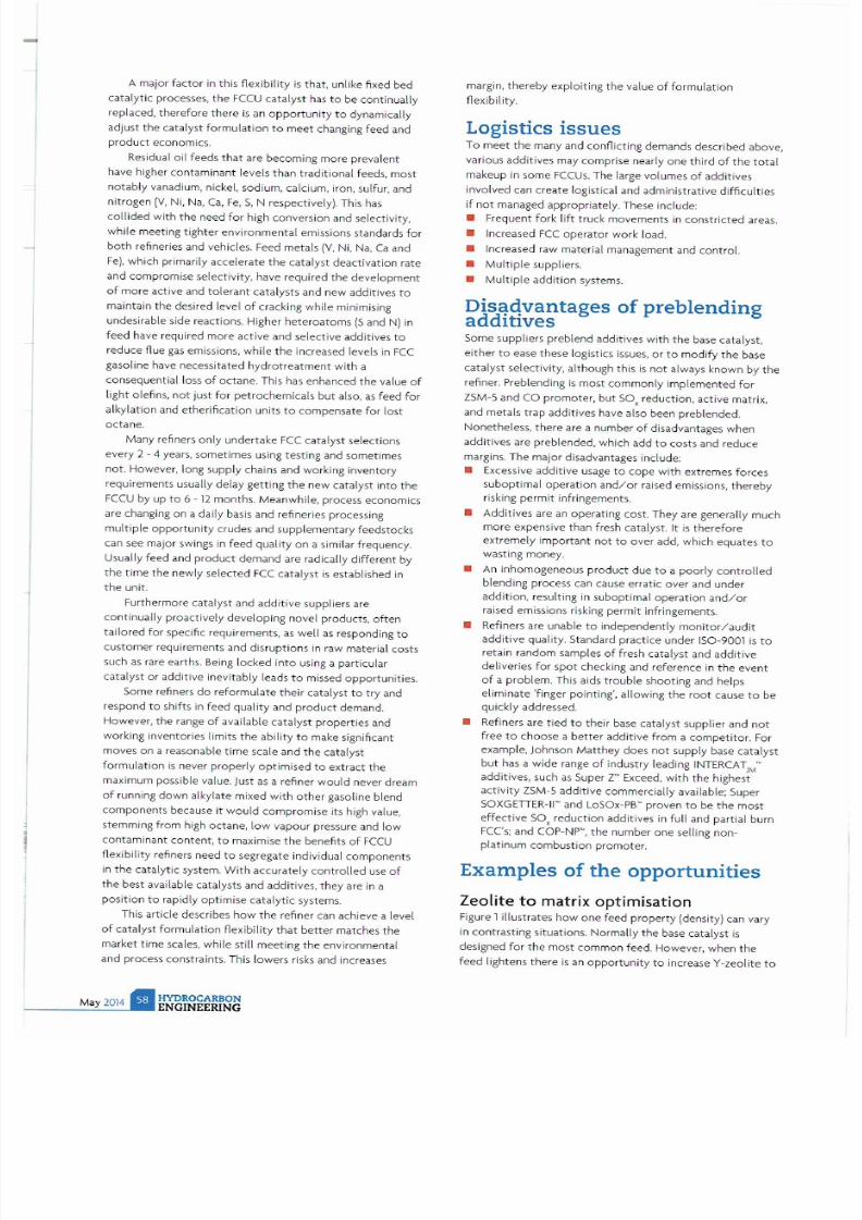
7/21/2019 Hydrocarbon Engineering Mayo 2014 Vol 19 05
http://slidepdf.com/reader/full/hydrocarbon-engineering-mayo-2014-vol-19-05 59/107
A major factor in this
flexibility
is that, unlike fixed bed
catalytic processes, the FCCU
catalyst
has to be continually
replaced ,
therefore
there is an opportunity to dynamically
adjust the catalyst formulation to meet changing feed and
product
economics.
Residua l
oil
feeds that are becoming more prevalent
have higher contaminant levels than traditional feeds, most
notably
vanadium, nickel. sodium, calcium, iron. 5ulfur, and
nitrogen V
, Ni ,
Na, Ca , Fe ,
S,
N respectively). This has
collided
with
the need
for high
conversion
and selectivity.
while meeting tighter environmental emissions standards for
both
refineries and vehicles. Feed metals
V, Ni
, Na,
Ca
and
Fe). which primarily accelerate the catalyst deactivation rate
and compromise selectivity, have required the development
of
more active and tolerant catalysts and new addit ives to
maintain the desired level
of
cracking while minimising
undesirable side reactions. Higher heteroatoms S and N) in
feed ha ve required more active and selective additives to
reduce flue gas emissions, while
the
increased levels in Fee
gasoline have necessitated
hydrotreatment
with
a
consequential loss of octane. This has enhanced the value of
light olefms, not just for petrochem icals but also,
as
feed for
alkyl
at
ion and etherification units to compensate
for
lost
octane.
Many refiners only undertake Fee catalyst selections
every 2 - 4 years, sometimes using testing and sometimes
no t. However, long supply chains and working inven tory
reqUirements usually del
ay
gett ing the new catalyst into the
FCCU by up to 6 -
12
months. Meanwhile, process economics
are changing on a daily basis and refineries processing
multiple opportunity
crudes and supplementary feedstocks
can see major swings in feed
quality on
a similar frequency.
Usually feed and product demand are radically
different
by
the time
the newly selected Fec catalyst
is
established in
the unit.
Furthermore catalyst and additive suppliers are
continually proactively developing no vel products,
often
tailored for specific requirements,
as
well as responding to
customer requirements and disruptions
in
raw material costs
such
as
rare earths. Being locked i
nto
using a particular
catalyst or additive inevitably leads to missed opportunities.
Some refiners do reformulate their catalyst to
try
and
respond to shifts in feed quality and product demand.
However, the range
of
available catalyst propert ies and
working inventories limits the
ability to
make significant
moves on a reasonable time scale and
the
catalyst
formulation is never properly optimised to extract the
maximum possible value. Just
as
a refiner would never dream
of running
down
alk
ylate
mixed with other gasoline blend
components because it would compromise its high value,
stemming
from
high octane, low vapour pressure and low
contaminant content, to maximise
the
benefits of FCCU
flexibility
refiners need to segregate indi vidual components
in
the catalytiC system.
With
accurately controlled
use of
the best available catalysts and additives, they are in a
position to rapidly optim ise catalytiC systems.
This article describes
how
the
refiner can achieve a level
of
catalyst formulation flexibility
that
better matches the
market time scales, while still meeting the environmental
and process constraints. This lowers risks and increases
HYDROCARBON
ENGINEERING
margin, thereby exp loiting t he value
of
formulation
flexibility .
Logistics issues
To meet
the
many and conflicting demands described above,
va rious additives may comprise nearly one third of
the
total
makeup in some FCCUs. The large vo lumes of additives
involved can create logistical and administrative difficulties
if not managed appropriately. These include:
• Freq uent fork
lift
truck movements
in
constricted
areas.
• Increased
Fce
operator work load.
• Increased raw material management and controL
• Multiple suppliers.
• Multiple
addition
systems.
i s ~ q v a n t a g e s
of preblending
addItIves
Some suppliers preblend additives with the base catalyst.
either to ease these logistics issues, or to modify
the
base
catalyst selectivity, although this
is
not
always known by
the
refiner. Preblending is most commonly implemented for
ZSM-S and CO promoter, but SOx reduction, active matrix,
and metals trap additives have also been preblended.
Nonetheless, there are a number
of
disadvantages when
additives are preblended, which add to costs and reduce
margins. The major disadvantages include:
• Excessive add itive usage to cope with extremes forces
suboptimal operat ion and/or
rai
sed emissions, thereby
risking permit infringements.
• Additives are an operating cost. They are gener<llly much
more expensive than fresh catalyst. It
is
therefore
extremely important not to over add, which equates to
wasting money.
• An inhomogeneous product due to a
poorly controlled
blending process can cause erratic over and under
addition, resulting in suboptimal operation
and/or
raised emissions risking
permit
infringements.
• Refiners are unable
to
independently monitor/audit
additive quality. Standard practice under ISO-9001 is
to
retain random samples of fresh catalyst and additive
deliveries for
spot
checking and reference in
the
event
of
a problem. This aids trouble shooting and helps
eliminate 'finger pointing', alloWing the
root
cause
to
be
qU ickly addressed.
• Refiners are tied to their base catalyst supplier and not
free
to
choose a
better
additive
from
a
competitor
For
example,
lohnson Matthey
does not supply base catalyst
but
has a
wide
range of industry leading INTERCAT
JM
add itives, such
as
Super Z Exceed, with the highest
activity
ZSM -S additive commerCially available; Super
SOXGETTER
-
II
- and LoSOx-PS proven
to
be the most
effective
sax
reduction additives in full and partial burn
FeC's; and COP-NP , the number one selling non-
plat
inum combustion promoter.
xamples of the opportunities
Zeolite to
matrix
optimisation
Figure 1 illustrates
how one
feed
property
(density) can vary
in contrasting situations. Normally the base catalyst is
deSigned
for
the most common feed. However, when the
feed lightens there is an
opportunity
to increase V-zeolite
to

7/21/2019 Hydrocarbon Engineering Mayo 2014 Vol 19 05
http://slidepdf.com/reader/full/hydrocarbon-engineering-mayo-2014-vol-19-05 60/107
)
/
i
The only word you
need
to remember
in
the
world
of
specialty
gases.
Hgh purity gases
ISO
accredited ca libra
ti
on gas
mixtures
and precision gas contro l equipmen t
for
laboratories
research
institutes and universities.
http: hiq.linde-gas .co
rn
Hi
Q Pr
ec
ision matt
ers
in
eve
rything
we
do.
HiQ isa registered
tradem
a
rk 1
The Unde Group.
Und
e
G
Unde
Gases Di
vision, Seitners
lrasse
70,
82049 P
uliach, Germany
Phone
49.89.74 46-1661
hiQ@l
inde-gas.com,
hltp:
hi
Q.linde-gas.com
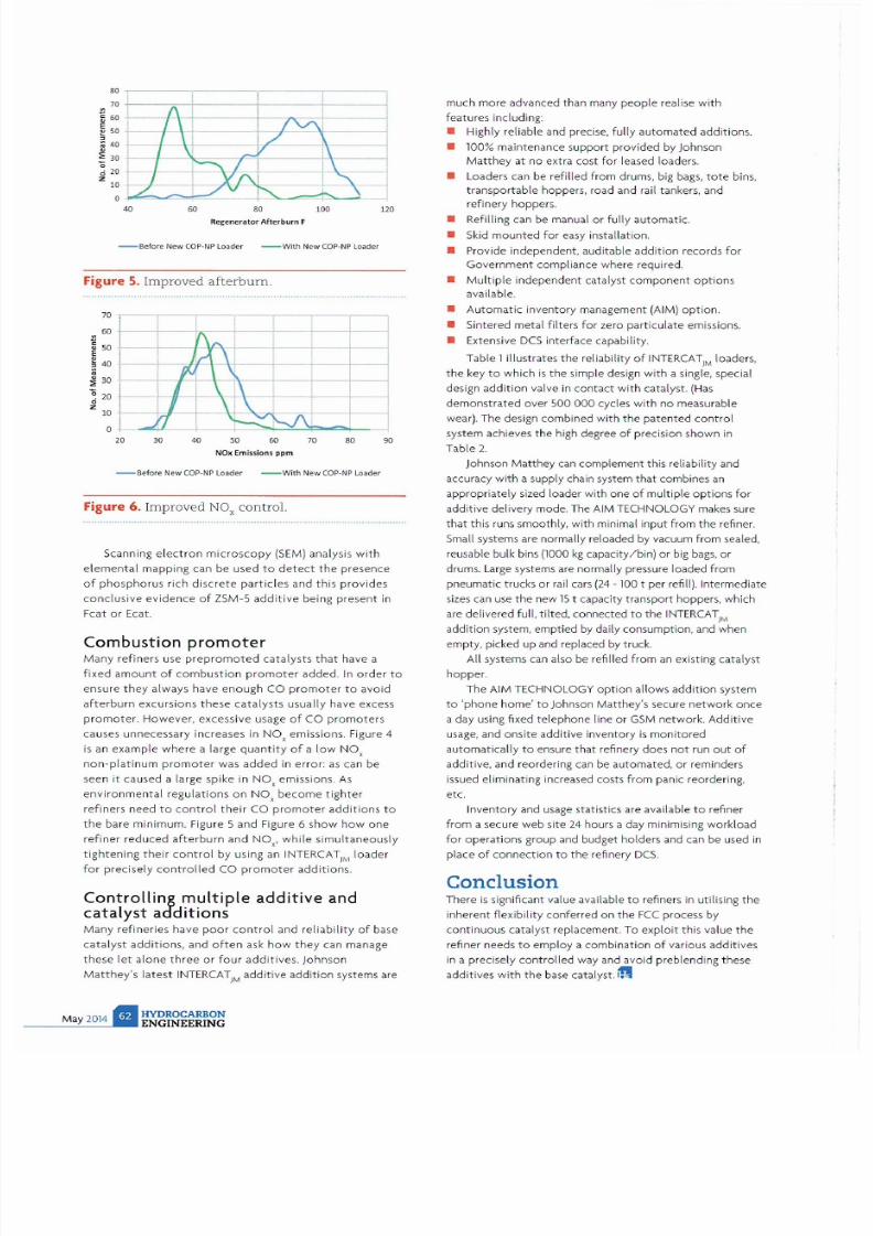
7/21/2019 Hydrocarbon Engineering Mayo 2014 Vol 19 05
http://slidepdf.com/reader/full/hydrocarbon-engineering-mayo-2014-vol-19-05 61/107
1
I
1
\
I \
~
I \ ./
I \
I
\
I
1\
80
70
60
50
40
30
20
10
o
I
I .
YA
[ ,
./
·v
£
r ... ~
4
6 80 100
Regenerator
After
burn F
- Before New COP -NP
loade
r - With New COP -NP Loader
Figure
5.
Improved afterbum .
70
60
SO
E
40
30
20
o
z
10
o
-\
~
_
N
A
\
\
I
~
I
rJ
-J\.I
20 30 4 50 60 70
80
NOK Emissions p
pm
- Before New COP-NP
Loader
- With New
COP
-
NP
Loader
Figure 6. Improved NO , control.
120
90
Scanning
electron microscopy
SEM)
analys is wi
th
elemental
mapping can be used to
detect the
presence
of
phosphorus
rich
discrete particles
and this
provides
conclusive evidence of ZSM-5
additive
being present in
Feat or Ecat.
Combustion
promoter
Many refiners
use prepromoted catalysts
that have a
fixed amount of
combustion
pr
omoter
added. In order to
ensure they always have enough CO promoter to avoid
afterburn
excursions
these
catalysts usually have excess
promoter. However, excessive usage of CO promoters
causes unnecessary increases in NO
x
emissions. Figure 4
is an example where a large
quantity of
a low NO
x
non-platinum promoter was added in error: as can be
seen
it
caused a large spike in
NO
x
emissions. As
environmental regulations
on
NO
x
become tighter
refiners need to control their CO promoter
additions
to
the bare
min
imum. Figure 5 and Figure 6 show how one
refiner
reduced afterburn and
NO
x
wh i le Simultaneously
tightening their control
by using an INTERCAT)M loader
for precisely
controlled
CO promoter add itions.
Controlling multiple additive and
catalyst
additions
Many
refineries have
poor control
and rel
ia
bility
of
base
catalyst additions, and often ask how they can manage
these let alone three or four addit ives. Johnson
Matthey s latest
INTERCAT M additive addition systems are
much more advanced than many people realise w ith
features includi
ng:
• Highly reliable and precise,
fully
automated additions.
• 100% maint enance support proVided by Johnson
Matthey at
no
extra cost for leased loaders.
• Loaders can be refilled from drums, big bags, tote bins,
transportable hoppers, road and rail tankers, and
refinery hoppers.
• Refilling can be manual or fully automatic.
• Skid mounted for easy installation.
• Provide independent, aud itable
addition
records
for
Government compl iance where required.
• Mu
lt
iple independent catalyst
component options
available.
•
Automat
ic i nventory management (AIM)
option.
•
Si
ntered metal filters
for
zero particulate emissions.
• Extensive DCS interface capability.
Table 1 i
ll
ust rates
the
reliability
of
JNTERCAT)M oaders,
the
key
to
which
is
the simple design
with
a Single, speCial
design addition valve in
contact with
cata lyst.
Has
demonstrated over 5
cydes
with
no
measurable
wear). The design combined
with the
patented control
system achieves the high degree
of
precision sh
own
in
Table 2.
Johnson Mat they
can
complement th is reliability and
accuracy
with a supply chain system that combines an
appropriate ly sized loader with one of multiple options
for
additive delivery mode. The AIM TECHNOLOGY makes sure
that this runs smoothly, with minimal input from the renner.
Small systems are normally reloaded by vacuum from sealed,
reusable bulk bins
(1000
kg
capacity/bin)
or
big
bags,
or
dr
ums.
La rge systems are norma
ll
y pressure loaded from
pneumatic trucks or rail
cars
(24
- 100
t per refill). Intermediate
sizes can use the new 15 t capacity transport hoppers, which
are delivered full, tilted, connected tothe I
NTERCAT
M
addition system, emptied by dai ly consumption, and when
empty , picked up and replaced by truck.
All systems
can
also be refilled from an existing catalyst
hopper.
The AIM TECHNOLOGY option allows add ition system
to phone home to Johnson Matthey s secure
network
once
a day
usi
ng fixed telephone line or GSM network.
Additive
usage, and onsite additive inventory is
monitored
automatically to ensure t hat refi nery does not run
out of
additive, and reordering can be automated,
or
reminders
issued eliminating increased costs from panic reordering,
etc.
Inventory and usage statistics are available
to
refiner
from
a secure web site
24
hours a day minimising workload
for operations group and budget holders and can be u
sed
in
place
of
connection
to
the refi nery
DCS.
Conclusion
There is Significant value available to refiners in utilising the
inherent flexibili ty conferred on the FCC process by
continuous catalyst replacement. To exploi t this value
the
refiner needs to employ a combination of various additives
in a preCisely
controlled
way and avoid preblending these
additives with
the
base catalyst. 1
t
7/21/2019 Hydrocarbon Engineering Mayo 2014 Vol 19 05
http://slidepdf.com/reader/full/hydrocarbon-engineering-mayo-2014-vol-19-05 62/107
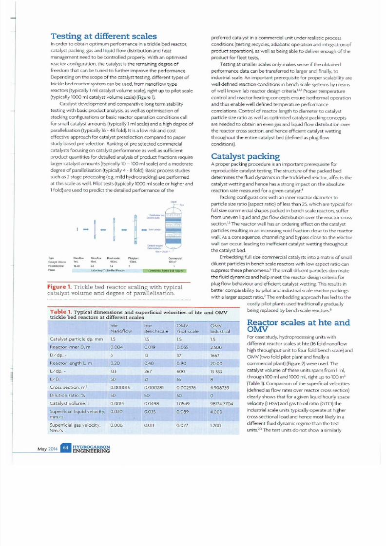
7/21/2019 Hydrocarbon Engineering Mayo 2014 Vol 19 05
http://slidepdf.com/reader/full/hydrocarbon-engineering-mayo-2014-vol-19-05 63/107
Testing
at
different scales
In order to obtain optimum performance in a trickle bed reactor,
catalyst packing, gas and
liquid
flow distribution and heat
management need to be controlled properly. With an optimised
reactor configuration. the catalyst
is
the remaining degree of
freedom
that
can
be
tuned
to
further improve
the
performance.
Depending on the scope of
the ca
ta
lyst
testing. different
types
of
trickle bed
reactor system can
be used. from
nanoflow
type
reactors
typically
1
ml
catalyst volume
scale), right up
to pilot scale
typically
1000
ml
catalyst volume
sca
le) Figure
1).
Catalyst development
and
comparative long term stability
testing with basic product analysis,
as
well
as
optimisation of
stacking configurations or basic reactor operation conditions call
for
small
catalyst amounts typically 1
ml
scale)and a high degree of
parallelisation (typi
call
y 16 - 48
fold). It
is a low ri
sk
and cost
effective approach
for
catalyst preselection compared to paper
study based pre selection. Ranking of pre selected commercial
catalysts focusing on catalyst performance as well as sufficient
product quantities
for
detailed ana lysis of product fractions require
larger catalyst amounts typically
10
100
ml
scale) and a moderate
degree of parallelisation typically 4 - 8 fold). Basic process studies
such
as 2
stage processing
e.g. mild hydrocracking)
are performed
at this scale as well. Pilot tests typically 1000 ml sca le or highe r and
1
old)
are used to predict the detailed performance of the
1- 1_
-
_
,
1(kri 100TIl
..
H
l.IIbcJlIlr) T
ncI Je.fled
Reactor
' ' '
OOm
'
Figure 1. Tri
c
kl
e bed
reactor
scaling w ith
typical
catalyst
volume
and degree
of
parallelisation.
preferred catalyst
in
a commercial unit under realistic process
conditions (testing recycles, adiabatic operation and integration of
product separation), as
well
as
being
able to deliver enough of the
product for fleet tests.
Testing at smaller scales only makes sense
if
the obtained
performance data can be transferred to
larger
and , finally, to
industrial sca l
e.
An important prerequisite for proper scalability are
well
defined reaction conditions in bench scale systems
by
means
of well known lab reactor design criteria.1 2 3 Proper temperature
control and reactor heating concepts ensure isothermal operation
and
thus enable
well
defined temperature performance
correlations. Control of reactor length to diameter to catalyst
particle
size
ratio
as well
as optimised catalyst
packing
concepts
are needed to obtain
an
even
gas
and liqUid flow distribution over
the reactor cross section, and hence efficient catalyst wetting
throughout the entire catalyst bed defined
as plug
flow
conditions).
Catalyst packing
A proper pac k
ing
procedure
is
an important prerequisite for
reproducible catalyst testing. The structure of the packed bed
determines the fluid dynamiCS
in
the tricklebed reactor, affects the
catalyst wetting and hence has a strong impact on the absolute
reaction rate measured for a given catalyst
4
Packing
configurations with
an inner
reactor diameter to
particle
size
ratio (aspect
ratio)
of
less
t
han
25,
which
are
typical for
full
size commercial shapes packed in bench scale reactors, suffer
from
uneven
liquid
and gas
flow
distribution over the reactor cross
section.
1 3
The reactor
wall has an
ordering effect on the catalyst
particles
resulting
in
an increasing void
fraction close to the reactor
wall.
As
a consequence, channe l
ing and bypass
close to the reactor
wall
can
occur,
leading
to inefficient catalyst wetting throughout
the catalyst
bed.
Embedding
futl size commercial
ca
talysts into a
matrix
of
small
diluent particles in bench scale reactors
with low
aspect ratio can
suppress these phenomena.
5
The small diluent particles dominate
the fluid dyna
mics
and help meet the reactor design criteria for
plug flow
behaviour and
effic
ient catalyst wetting. This results in
better comparability to pilot and
industrial sca
le reactor
packings
with a larger aspect ratio.2
The
embedding approach has
led
to the
costly pilot plants used traditionally gradually
able
1. Typical d im
ension
s a
nd
s
uper fi
cial velocities of hte and
OMV
trickle bed react
ors
at different scales
being
replaced by bench scale reactors.
6
Reactor scales
at hte
and
OMV
r ht
Nanoflow Benchscale
Catalyst particle dp, mm
1.5
15
Reactor inner D, m
0.004 0.019
D/dp
. -
3
13
Reactor length L, m
0.20 0.40
Udp . - m 267
L/D
, -
50
21
Cross
section, m
2
0.000013 0.000281
Dilution ratio, % 50
50
Catalyst volume,
0.0013
0.
0498
Superficial liquid velocity,
0.
020
0.035
mm/s
SuperfiCial gas velOCity,
0.
006
O
Otl
Nm/s
HYDROCARBON
ENGINEERING
OMV
Pilot scale
1.5
0.055
37
0.90
600
16
0 .002376
50
1.0549
0.
089
0.027
OMV
Industrial
1.5
2.500
1667
20.00
Bm
8
4.908739
0
98174 .7704
4.
000
1.200
For case study, hydroprocessing units
with
different reactor scales at hte 16
fold
nanoflow
high throughput unit to four fold bench sca le) and
OMV (two fold pilot plant
and fina il
y a
commer
cial plant)
(Fi
gure 2)
were
used. The
catalyst
vo
l
ume
of these
units
spans
from
1
ml,
through
100 ml
and 1000
ml
,
right up
to
100
m
3
Tab le 1). Comparison of the superficial velocities
(defined
as
flow rates over reactor cross section)
clearly shows that for a given
liquid
hourly space
velOCity
LHSV) and gas to oil ratio GTO) the
indust
ri
al scale units typically operate at higher
cross sectional load and hence most likely
in
a
different fluid dynamiC regime than the test
units.u The test units do not show a Similarly

7/21/2019 Hydrocarbon Engineering Mayo 2014 Vol 19 05
http://slidepdf.com/reader/full/hydrocarbon-engineering-mayo-2014-vol-19-05 64/107
dramatic difference among each other with respect
to superficial
velocities. They lie within a range of factor
four.
Alignment
is
possible
by
adjusting the reactor length to diameter ratio.
Testing units typically
work
with smaller diluent particles
to
improve isothermal operation and
fi ll up
the
void
space
for
better
gas
and
liqUid distribution. A decrease in void space results
in an
increase
in
the actual interstitial velocities . Nonetheless, this further
increase by smaller diluent particles cannot compensate
reaching
the
much higher
cross sectional load
of industrial
scale.
Consequently, the strategy for test units is not necessarily to
reproduce the exact same
fluid dynamiC
profile as
in
the
commercial unit Instead, techniques
such as
catalyst embedding
are applied to assure
an
even
flow
distribution throughout the
entire reactor cross section. Th is plug flow profile in the trickle bed
reactor and the resulting efficient catalyst wetting ensure optimum
catalyst utilisation and avoid
masking
artefacts from poor fluid
dynamiCS.
Hydroprocessing case studies
The case studies presented here comprise an independent catalyst
ranking of two full size commercial catalyst systems Aand B or
two stage
mild
hydrocracking MHq of vacuum
gas
oil (VGO) with
1
wt /o
sulfur and
1000
ppm nitrogen. In the first case study, the
HDS/HDN catalysts Aand B n the firs t MHC reactor stage were
ranked
against each other reactor pressure 60
bar(gl
, L SV l.5l/hr,
GTO 300
NI lt
r).
The
ranking was performed in a hte 6 fold high
throughput system (nanoflow), as we ll as in
an
hte four fold bench
scale
un
it.
The
setup comparison was done to prove the
possibility
of reasonable downscaling of full
size
commercial catalyst
ranking
rlO n
lypical
bench scale lo lml scale.
In
the second case study, the
base case
MHC
catalyst system A
was util
ised to compare the hte
bench scale un it with the O V pilot plant
for
the combined two
stage MHC ofVGO
reactor pressure
60 bar g)
,
LHSV
0.7211h, GTO
300 NI/ltr). In all cases, the apparent rate constants were obtained
with irreversibl
e,
ideal plug flow kinetics with reaction order n =1.67
Downscaling from
hte
bench
scale to hte nanoflow scale
Two
fu
ll size commercial quadrilobe extrudate catalysts A
and
B
were ranked in the nanoflow system and in the bench scale
unit
accor
ding to
defined test protocols
for
combined
hydrodesulphurisat ion
HDS) and
hyd rodenitrification HDN) of
VG0
Some difference exists between both tests due to somewhat
different
run
modes. The bench scale unit was operated in a
constant
MHC
conversion mode,
i.e.
the temperature was adjusted
to maintain a certain conversion. The high throughput unit was
operated in a temperature scan mode,
i.e.
the temperature was
increased stepwise over defined time intervals
in
order to produce
a temperature history and
run
time close to the one
in
the bench
scale unit. Thus, the test protocols for the two units were not
identical but close enough to ensure a reasonable level of
comparability.
The
catalyst activation protocol was
identical.
The high
throughput
un
it
was
additionally used to measure the
HDS/HDN kinetics
over a broader temperature
range
than that
offered
by
the catalyst
ranking
protocol.
Figure
3 shows
HDS
conversion and the corresponding apparent rate constant
for
full
size
extrudate catalysts Aand B
as
well
as
catalyst A crushed to a
powder fraction as a function of temperature.
Commercial catalyst ranking is typically performed under
industrially
relevant conditions, i.e.often at hi
gh
conversion
levels
Figure 2. Reactors
at
different scales from
left
to right):
16
fold high throughput unit
at
hte
nanoflow). 4 fold bench scale
unit
at hte, 2 fold
pilot
at OMV,
commercial plant
at
OMV.
iii
;<
E
c
0
u
E
•
120
100
80
60
40
20
0
sso
900
800
-
700
-
600
500
400
300
200
100
o
580
/
/
- 8 · exlrudates
- A· powder
- A • exlrudates
.
_.-
.
600 620 640
660 680
Temperature I KJ
8 • exlrudates
I
A· powder
/
- A • exlrudates
/
/
/ /
/ / /
/ / /
~ ~
-
_ _
-
600 620 640
660 680
Temperature I KJ
Figure 3. Comparison
of
HDS
kinetics: conversion
left)
and
apparent rate constant right), for full
size commercial catalysts A and B, as well as base
case
A in crushed powder form.
far in
excess of
90%
conversion for
HDS/HD N. As
can be seen
in
Figure
3,
the measured conversion differences are
very
small in this
domain,
while
the calculated apparent rate constants expand the
difference. As a consequence, the conversions
in this
domain must
be determined with absolute preciSion in order
to
accurately
distinguish even slight conversion differences and avoid
experimental artefacts that are blown up when converted
to
rate
constants. An imperative prerequisite
for this is
a reprodUCible
catalyst packing protocol
ensuring
plug flow
since
artefacts
from
uneven flow distribution and incomplete catalyst utilisation may
significantty
corrupt the catalyst
ranking.
The
result
of
the comparati
ve
catalyst ran
king in
the nanoflow
and bench scale unit
F
igure
4)
shows that catalyst B
s
approximately 2.5 times more active than catalyst
A.
Although
there is a slight deviation between both setups due to different run
modes, the catalyst
ranking
on both scales lead to the same
HYDROCARBON

7/21/2019 Hydrocarbon Engineering Mayo 2014 Vol 19 05
http://slidepdf.com/reader/full/hydrocarbon-engineering-mayo-2014-vol-19-05 65/107
D
esigning and
manufacturing complete thermal
systems is
Watlow s expertise
We
have over 20
years experience
working
our
energy
process
customers
to
determine
optimum
therma
l
process heating applications.
supplies engineering deSign,
services and products for:
Liquefied Natural Gas (LNG)
as Dehydrat
i
on
and Sweetening
Catalytic Cracking
and
Regeneration
Polycrystalline Sl icon
Ingot
Production
Nuclear
Pressurizers
Watlow today for
the
best thermal solution
process application
Technical Sales Offices
+49 0) 7253-9400 -0
Info@watlow de
1
3
314132797
info@watlow fr
I
taly
+39 0) 2 4?8-8841
italyinfo@
wat
low com
pain +349
1 675 129 2
Info@watlow. s
U +44 0) 5-964-0777
n
t
5.
le ,
th

7/21/2019 Hydrocarbon Engineering Mayo 2014 Vol 19 05
http://slidepdf.com/reader/full/hydrocarbon-engineering-mayo-2014-vol-19-05 66/107
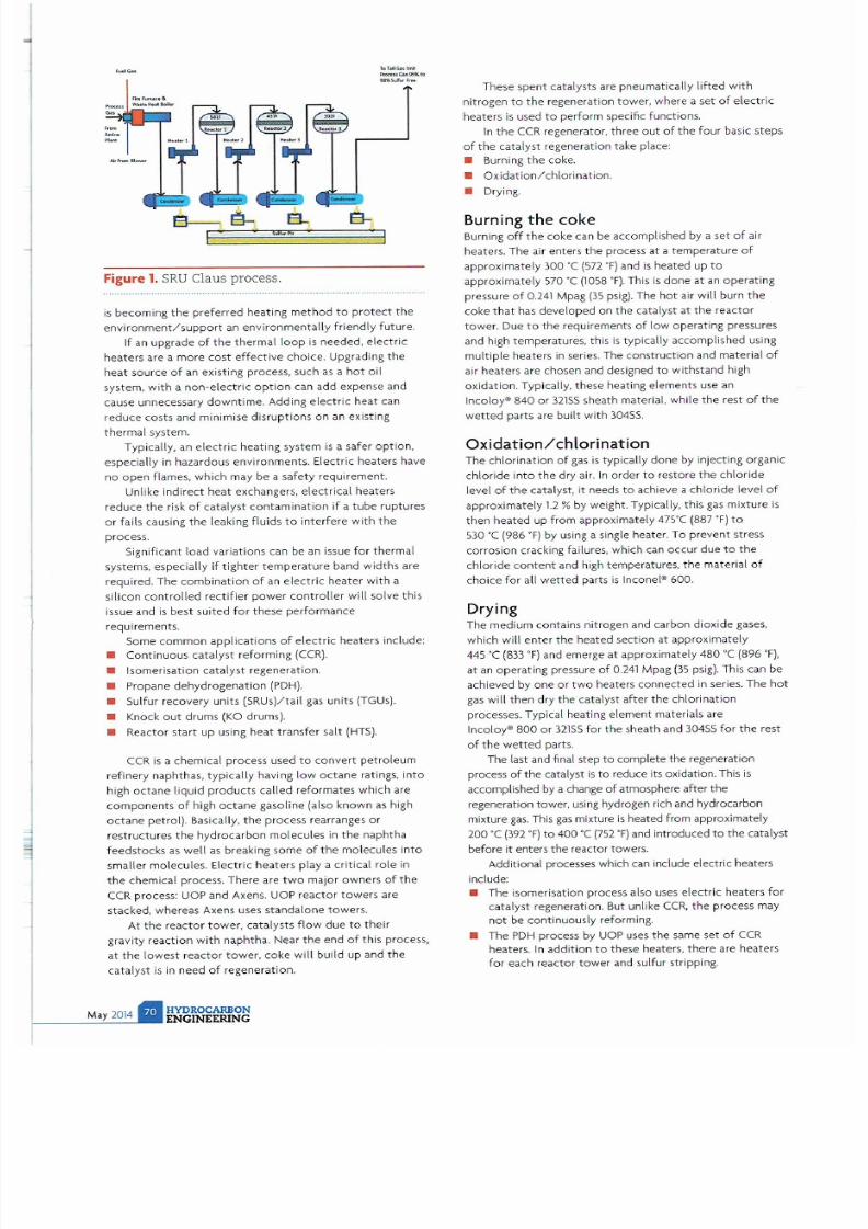
7/21/2019 Hydrocarbon Engineering Mayo 2014 Vol 19 05
http://slidepdf.com/reader/full/hydrocarbon-engineering-mayo-2014-vol-19-05 67/107
,...
r . a
B S
I
EL
' ... Pi
Figure 1.
SRU
Claus process.
.. T
.........._
.
. . loI\
.. r ..
-
is
becoming
the
preferred
heating
method to protect
t
he
environment/support
an environmentally friendly future.
If an upgr
ade
of the t hermal loop
is needed.
electric
heaters
are a
more
cost
effective
choice. Upgrading
the
heat
sou
r
ce
of
an existing process, such as a
hot
oil
system, with a
non-electric option
can
add expense
and
cause
unnecessary
downtime.
Adding
electric
heat can
reduce costs
and minimise disruptions
on
an existing
thermal
system.
Typically. an
electri
c heating system
is
a safer
option
espec
ially
in
haza r
do
us environments. Electric
heaters
have
no
open
flames, which may be a
safety
requirement.
Unlike indirect
heat
exchangers, electrical
heaters
reduce the risk
of
catalyst contamination
if a
tube
ruptures
or
fails causing
the
leaking fluids to
inte
rfe re with
the
process.
Significant load variations can be an issue for thermal
syste
m
s,
especial ly if
tighter tempe
r
ature
band widths are
requi red. The
combination
of an
electric heater
with a
silicon
controlled
rectifier
power
controller
will solve this
issue and
is best suited
for
these performance
requirements.
Some
common
applications
of
electric
heaters
include:
• Continuous
catalyst
reforming
CCR).
• Isomerisation
catalyst
regeneration.
• Pr
opane
dehydrogenation
PDH).
• 5ulfur recovery units {SRUs)/tail gas units TGUs).
• Knock
out
drums
KO
drums).
• Reactor
start
up using hea t transfer salt
HTS).
CCR
is
a chemical
process
used to
convert petroleum
refinery naphthas. typically having low
octane
ratings, into
high
octane
liquid
products
called
reformates
which are
co m
ponents
of high oc t
ane gaso
line (also known as high
oc t
ane
petrol). Basically, the
process
rearranges
or
restructures
the
hydrocarbon
molecules
in the
naphtha
feedstocks
as well as breaking
some
of
the
molecules
into
smaller molecules. Electric
he
a
te
rs play a critical role
in
the
chemical process. There are
two
major
owners
of
the
CCR process: UOP and Axens. UOP r
eactor towers
are
stacked, whereas Axens uses s
ta ndalone
towers.
At t
he
r
eactor towe
r, catalysts flow
due
to
their
gravity reaction with naphtha. Near
the end
of this process,
at
t he
lowest
reactor
tower,
coke
will build up and
the
ca
talyst
is
in
need
of
regeneration.
These
spent
catalysts are pneumatically lifted with
nitrogen
to the
regeneration tower, where a
set
of
electric
heaters
is
used to perform speCific functions.
In the CCR
regenerator,
three out
of
the
four basic
steps
of the
catalyst regeneration take place:
• Burning the coke.
•
Oxidation/chlorination.
• Drying.
Burning
the
coke
Burning
off the
coke can be accomplished by a
set
of air
heaters. The air enters
the
process
at
a
temperature
of
approx imately 300 'C 572 ' F and is heated up to
approx imately 570 ·C
1058
·
F .
This
is
done
at an
operating
pressure of
0.241
Mpag
35
psig). The
hot
air
will
burn
the
coke
that
has
developed
on
the
catalyst
at
the reactor
tower. Due
to
the
requirements
of
low operating pressures
and high
tempe
ratures, this
is
typically accomplished using
multiple
heate
rs
in
series. The construction and
mater
i
al of
air heaters are chosen and designed
to
withstand high
oxidation. Typically,
these
heating elements use an
Incoloy·
840 or
32155 sheath material, while
the
rest of
the
wetted
parts are built with 30455.
Oxidation
/
chlorination
The chlorination
of
gas
is
typica lly done by inject ing o rgan ic
chloride into
the
dry air. In order to restore
the
chlori
de
level of
the
catalyst, it needs to achieve a chloride level of
approximate
ly
1.2
by weight. Typically, this gas mixture
is
then
heated
up from approximately
47S
·C (887
O) to
530 ·C (986
OF
by using a Single heater. To
prevent
stress
corrosion cracking failures, which can
occur due
to
the
chloride
content
and high temperatures,
the
material of
ch
oice
for all
wetted
parts
is
Inconel® 600.
Drying
The medium contains nitrogen and carbon dioxide gases,
which will ente r
the heated
section
at
approximately
445 'C
833 OF
and emerge
at
approximately 480 'C (896 O
,
at
an operating pressure of
0.241
Mpag
35 psi g).
This can be
achieved
by one
or
two heate
rs
connected in
series. The
hot
gas will
then
dry
the
catalyst afte r
the
chlorination
processes. Typical heating element materials are
Incoloy·
800
or
32155
for
the
sheath and 30455 for
the
rest
of the wetted
parts.
The
las
t and final
step
to
complete
the
regeneration
process of
the
catalyst is
to
r
educe
its oxidation. This
is
accomplished
by
a change
of
atmosphere
her the
regeneration
towe
r. using hydrogen rich and hydrocarbon
mixture gas. This gas mixture
is
heated from approximately
200 ·C
392 OF to
400 °C
752 O
and introduced
to
the
catalyst
before it enters
the
r
eactor
towers.
Add
itional processes which can include electric heaters
include:
• The isomerisation process also uses e lectric
heaters
for
catalyst regeneration. But unlike
CCR,
the
process may
not
be
co
ntinuously reforming.
• The
PDH
process by
UOP
uses
the
same
set
of CCR
heaters.
In
addition
to
these
heaters,
there
are
heaters
for
each
reactor
tower
and sulfur stripping.

7/21/2019 Hydrocarbon Engineering Mayo 2014 Vol 19 05
http://slidepdf.com/reader/full/hydrocarbon-engineering-mayo-2014-vol-19-05 68/107

7/21/2019 Hydrocarbon Engineering Mayo 2014 Vol 19 05
http://slidepdf.com/reader/full/hydrocarbon-engineering-mayo-2014-vol-19-05 69/107
Figure 2. Electric heater for heat transfer salt for a
petrochemical plant in Korea.
•
SRUs
and
TGUs
play a vital role
in
reducing
the
sulfur
emisSion into the atmosphere. The quality of crude
being refined is getting dirtier whereas the
requirement for allowable sulfur emission
is
getting
tighter
USA ew Source Performance
Standards (NSPS)
for Petr
oleum
Refineries,
subparts
J
and
Ja
40
CFR
60.100). This combination
is
creating
new breeds of
SRUs
and
TGUs.
The traditional shell and tube heat exchangers are now
being replaced
by
electric heaters due to
the
benefits
stated earlie
r.
This also applies to
TGUs.
Knock out drums
are
used to separate fluids and
liquids
before another process or
flare.
The
fluids
are
heated
to lower
the viscosity fo r handling. Di rect
immersion
heaters
are typical fo r
this application.
Other petrochem
ical
processes
use
HTS
for
heating
reactor towers.
El
ectr
ic heate rs
are used to heat the HTS
during
start up
.
y p i ~ a l heater design
reqUlrements
• H
eaters
can be a single unit
or
several units
in
series,
depending on the
required outlet
temperature.
• Electrical
enclosures need
to
be explosion
proof and
certified
to
perform
in
hazardous
locations.
HYDROCARBON
ENGINEERING
• Pressu re
vessels
typically require a design to
meet the
requirements
of
and be stamped
as
ASME VI
II
Div 1
•
Heater bundles shou
ld be
designed without segmental
baffles to minimise
pressure drops
and avoid
possible
hot spots
from
dead
flow areas.
• Heating elements
need
to
be made
from
seamless
tubing
with
minimum wall thickness of
1.25
mm (0.049 in.) to
eliminate
failures
at the tube
seams and serve with
reliable high
performance.
100000 hrs of
continuous operation
are a typical life
cycle
for
these elements.
•
Heate
rs
should be
produced to
meet tighter
resistance
tolerances (within 5 ) and are
required
to
deliver
deSigned
wattages at
minimum
voltage
.
•
Heaters should be
used in
combination
with
SCR
controllers
, typically
two
leg burst fire.
• Heating
elements need
to be seal
welded
to
the
flange.
The use of
bite
coupling
or soldered
connections
is
not allowed.
Materials of
construction
To avoid
stress ch
l
oride
cracking
fai
lure
due
to
traces
of
HCI in the gas mixture,
most
chlorinat ion
heaters
require
the wetted
parts
(heater bundle
, flange and vessel) to
be
made of Incone -
600.
Air
heaters
use sta inless
steel
vessel and flanges with 321
SS or
Incoloy*
840 elements.
Regeneration
heaters
use stainless
steel
vessel and
flanges
with
Inco l
oy*
800 elements.
Care and maintenance of
heaters and
controllers
Electric
heaters
for the
mentioned applications
are major
investments. These
heaters
are
typ
ically ordered
and
delivered
several
months ahead
of
the
installation
and
startup process. These heaters
should be
kept in
a d ry
place, cove red
and
preferably
in
a low humidi ty
environment.
If the
site
has no
storage
room, the
heaters should be
kept in
a
crate
and
covered
wit h tarp to protect them
from
ra
in
or
sun.
If the heater element
has
been
deformed
during
handling, it
should be straightened to
avoid
touching
other elements. Otherwise, hot
spots
will be cr
eated,
which
result in
failure.
When the heate
rs
are
installed and running, a
good
regular
monthly check of
the e lectr ical
enclosure cooling
fan filters
should be
done
to
ensure good air flow
and
cooling
of
the thyristors in the
panel. For
heaters that
are
used for startup only and will
be on standby
for a few
months, a good nitrogen
or
dry air purge
in
the
enclosure
box will ensure a good isolation
of
the
heater fo
r the next
usage.
Finally, it is
recommended
to
perform maintenance or
inspections
of the
heater s electrical enclosure at least
once a
yea
r
to
make sure
the connections are tight and
show no
signs of
overheating
.
Conclusion
When properly
operated
and maintained,
electric heaters
have
been proven
to be in service
of
refineries
and
petrochemical
plants
well
above the
required 100
000
hrs
of
continuous
service,
i1 I

7/21/2019 Hydrocarbon Engineering Mayo 2014 Vol 19 05
http://slidepdf.com/reader/full/hydrocarbon-engineering-mayo-2014-vol-19-05 70/107

7/21/2019 Hydrocarbon Engineering Mayo 2014 Vol 19 05
http://slidepdf.com/reader/full/hydrocarbon-engineering-mayo-2014-vol-19-05 71/107

7/21/2019 Hydrocarbon Engineering Mayo 2014 Vol 19 05
http://slidepdf.com/reader/full/hydrocarbon-engineering-mayo-2014-vol-19-05 72/107
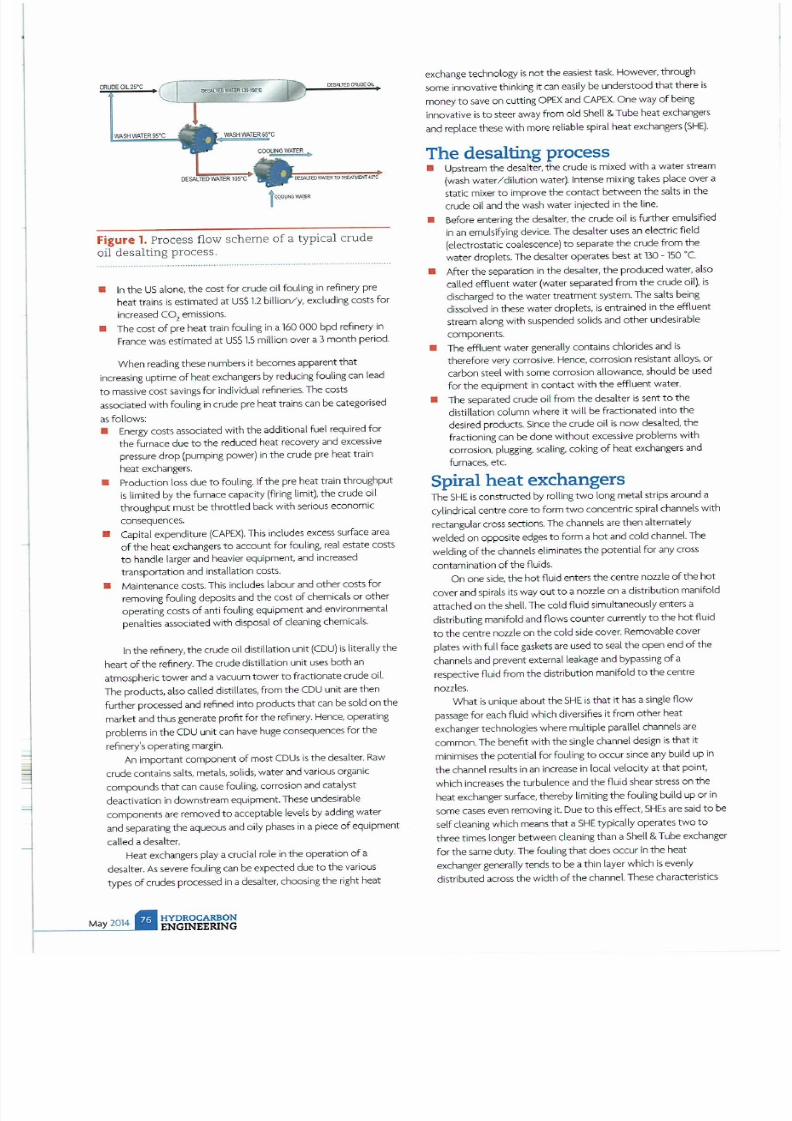
7/21/2019 Hydrocarbon Engineering Mayo 2014 Vol 19 05
http://slidepdf.com/reader/full/hydrocarbon-engineering-mayo-2014-vol-19-05 73/107
Figure 1. Process flow scheme of a typical crude
oil desalting process.
• In the
US
alone, the cost for crude oil fouling
in
refinery pre
heat trains is estimated at USS 1 2 billion/y excluding casts for
increased CO
2
emissions.
• The cost of pre heat train fouling in a 160 bpd refinery in
France was
estimated at
US
1 5
million over a 3month period.
When reading these numbers it becomes apparent that
increasing uptime of heat
exchangers by
reducing fouling can lead
to
ma5Sive cost savings for
individual
refineries.The costs
associated with
fouling
in crude pre heat trains can be categorised
as follows:
• Energy costs associated with the additional fuel required for
the
furnace due
to
the reduced heat recovery and excessive
pressure drop (pumping power) in the crude p
re
heat train
heat
excha
nger
s
• Production loss due to fouling. If the pre heat train throughput
is limited by the furnace capacity firing limit), the crude oil
throughput must be throttled back with serious economic
consequences.
• capital expenditure APEX). This includes excess surface area
of the heat exchangers to account for
fouling,
real estate costs
to handle larger and heavier eqUipment, and increased
transportation and installation costs.
• Maintenance costs. This includes labour and other costs for
removing fouling deposits and the cost of chemicals or other
operating costs of anti foul ing equipment and environmental
penalties associated
with
disposal of cleaning chemicals.
In
the refinery, the crude oil distillation
unit CDU)
is
literally
the
heart of the refinery. The crude distillation unit uses both an
atmospheric tower and a vacuum tower
to
fractionate crude
oiL
The products, also called distillates, from the (DU unit are then
further processed and refined into products that
can
be sold on the
ma
rket and thus generate profit for the
refinery.
Hence, operating
problems
in
the CDU unit can have huge consequences for the
refinery s operating
ma
rgin.
An important component of most CDUs is the desalter. Raw
crude contains salts, metals, solids, water and various organic
compounds that can cause
fouling,
corrosion and catalyst
deactivation in downstream equipment. These undesirable
components are removed to acceptable levels by adding water
and separating the aqueous and
Oily
phases
in
a piece of equipment
ca lled a desalter.
Heat exc hangers play a crucial role
in
the operation of a
desal
te
r
As
severe fouling can be expected due to the various
types of crudes processed
in
a desalter, chooSing the right heat
HYDROC RBON
ENGINEERING
exchange technology is not the easiest task. However, through
some innovative think ing it can eaSily be understood that there is
money to save on cutting
OPEX
and CAPEX. One way of being
innovative is to steer away from old Shell Tube heat exchangers
and
replace these with more reliable spiral heat exchangers
SHE).
The desalting process
• Upstream the desalter, the crude
is
mixed with a water stream
wash water/dilution water). Intense mixing takes place over a
static mixer to improve the contact between the salts
in
the
crude oil and the
wash
water injected
in
the
line.
• Before entering the desalter, the crude oil is further emulSified
in
an em u
lsifying device.
The desalter uses an electric field
(electrostatic coalescence) to separate the crude from the
water droplets. The desalter operates best at 130 • 150 ·C
• After the separation
in
the desalter, the produced water, also
called effluent water (water separated from the crude oil),
is
discharged to the water treatment system. The salts being
dissolved
in
these water droplets, is entrained in the effluent
stream
along
with suspended solids and other undesirable
components.
• The effluent water
generally
conta
ins
chlorides
and
is
therefore
very
corrosive. Hence,corrosion resistant alloys, or
carbon steel with some corrosion allowance, should be used
for
the equipment
in
contact with the effluent water.
• The separated crude oil
from
the desatter is sent to the
distillation column where
it
will be fractionated into the
desired products. Since the crude oil is now desalted, the
fractioning can be done without excessi
ve
problems with
corrosion, plugging,
scaling, coking
of heat exchangers and
furnaces, etc.
Spiral heat exchangers
The SHE
is
constructed by
rolling
two long metal strips around a
cylindrical centre core to
form
two concentric
spiral
channels with
rectan
gula
rcross sections. The channels are then alternately
welded on opposite edges to fo rm a hot and cold channel. The
welding of the channels eliminates the potential for any cross
contamination o f the
fluids
.
On one side, the hot fluid enters the centre nozzle of the hot
cover and spirals
its
way out to a nozzle on a distribution manifold
attached on the shell. The cold fluid Simultaneously enters a
distributing manifold and flows counter currently to the hot fluid
to the centre nozzle on the cold side cover. Removable cover
plates with
full
face gaskets are used to seal the open end of the
channels
and
prevent external leakage and bypassing of a
respective
fluid
from the distribution manifold to the centre
nozzles.
What
is
unique about the SHE
is
that
it has
a Single flow
passage for each
fluid
wh ich diversifies it
from
other heat
exchanger tec
hnologies
where multiple parallel channels are
common.
The
benefit with the
Single
channel design is that
it
minimises
the potential for
fouling
to occur since
any build up
in
the channel results
in an
increase in local velocity at that pOint,
which increases the turbulence and the fluid shear stress on the
heat exchanger surface, thereby limiting the fouling
build up
or
in
some cases even removing it.
Due
to this effect,SHEs are
said
to
be
self cleaning which means that a SHE typically operates two to
three times longer between cleaning than a She
ll
Tube exchanger
for the same duty. The fouling that does occur in the heat
exchanger generally tends to be a thin layer which is evenly
distributed across the width of the channel. These characteristics

7/21/2019 Hydrocarbon Engineering Mayo 2014 Vol 19 05
http://slidepdf.com/reader/full/hydrocarbon-engineering-mayo-2014-vol-19-05 74/107
M
i
d
s
tr
e
a
m
S
o
l
u
ti
o
n
s
w
it
h
I
n
d
u
s
t
r
y
-L
e
a
d
in
g
S
p
e
e
d
t
o
M
a
rk
e
t
To
w
in
a
rac
e
y
o
u n
e
ed
no
t
o
n
ly
sp
e
e
d
.
b u
t
a
t
im
e
ly
s
ta
rt.
M
e
r
ic
he
m
C
om
pa
n
y
h
as
a
p
ro
v
e
n t
r
ac
k
r
e
co
r
d
of
p
ro
v id
in
g
hy
d
ro
c
ar
b
on
tr
ea
t
in
g
s
olu
t
i
o
n
s
t
h
a t
m
e
e
t
th
e
stri
ng
e
n
t
tim
e
li
ne
s
o
f
ou
r
c
u
s
to
m
e
rs
.
G
e
t
yo
u
r
t
re
a
tin
g
p
ro
je
c
t
o
ff
to
a
t
im
e
ly
s
ta
rt
b
y
c
h
o
o
si
ng
M
e
ri c
he
m
C
o
m
p
a
n
y
a
s
y
ou
r
te
c
h
n
o
lo
g y
lic
e
ns
or
.
M
e
ric
h
em
Company
s
portfol io of midstream treating
technologi es
in
cl
ud
e
s
ou
r
pa
t
en
te
d
F
IR
R
F
ILM
4
t
Co
n
ta
ct
or
t
ha
t
o
ffe
rs
a
v
ar
ie
ty
o
f
ca
us
tic
,
a
m
in
e
a
nd
a
cid
tr
ea
tin
g
pr
oc
es
se
s
, M
e
ri
ch
e
m
al
so
o
ff
ers
s
ol
u ti
on
s f
or
g
as
tr
eo
ti
ng
, i
nc
lu
d i
ng
o
ur
pa
te
n
te
d
lO
· C
AT
i
w
et
s
cr
u
bbi
n
g,
li
qu
id
r
ed
ox
s
ys
te
m
th
o
t c
o
nv
er
ts
H2
S
10
i
n
n
oc
u
ous
.
el
em
e
nt
ol
s
ul
fur.
I
n
a
dd
it
ion
to
ou
r
l
or
ge
po
rt
la
no
of
lic
en
s
ed
tre
o
tin
g
tec
h
no
lo
g
ie
s,
M
er
ic
he
m
of
fer
s
ind
u
str
y l
ea
d
ing
sp
en
t
ca
us
ti
c
m
a
n
ag
em
e
n
t
s
er
vi
c e
s
th
a
t
u
tili
ze
b
en
e
fic
ia
l r
eu
se
o
pt
io
ns
to
c
re
a
te
0
so
lu
tio
n
f
or
yo
ur
s
p
en
t
c
a
u
s
t
ics
.
fo
r
fas
t,
e
ff
ec
ti
ve
tr
ea
ti
ng
s
ol
u ti
on
s,
ch
o
os
e
M
er
iC
h
em
.
T
h
i
n
k
F
a
s
t
T
h
i
n
k
M
e
r
i
c
h
e
m
w
e
e
t
S
o
l
u
t
i
o
n
s
®
a
t
t
h
e
p
e
e
d
o
f
Y
o
u
r
B
u
s
i
n
e
s
s
:
. .
M
E
Rle
H
EM
CO
M
PA
N
Y
I 5
45
5
O
d
S
po
n
h
T,a
il
I
H
ou
,'o
n. T
.,
m
77
02
3
I
7
13
.42
8
.50
00
I
J
::.
.
Co
p '
fl ig
h l
'
20 1

7/21/2019 Hydrocarbon Engineering Mayo 2014 Vol 19 05
http://slidepdf.com/reader/full/hydrocarbon-engineering-mayo-2014-vol-19-05 75/107

7/21/2019 Hydrocarbon Engineering Mayo 2014 Vol 19 05
http://slidepdf.com/reader/full/hydrocarbon-engineering-mayo-2014-vol-19-05 76/107

7/21/2019 Hydrocarbon Engineering Mayo 2014 Vol 19 05
http://slidepdf.com/reader/full/hydrocarbon-engineering-mayo-2014-vol-19-05 77/107

7/21/2019 Hydrocarbon Engineering Mayo 2014 Vol 19 05
http://slidepdf.com/reader/full/hydrocarbon-engineering-mayo-2014-vol-19-05 78/107

7/21/2019 Hydrocarbon Engineering Mayo 2014 Vol 19 05
http://slidepdf.com/reader/full/hydrocarbon-engineering-mayo-2014-vol-19-05 79/107

7/21/2019 Hydrocarbon Engineering Mayo 2014 Vol 19 05
http://slidepdf.com/reader/full/hydrocarbon-engineering-mayo-2014-vol-19-05 80/107
Optimize your plant for a safe efficient start-up
n
When co nsidering m
ec
hanica l pre-commi ssion ing and commi
ss
ioning for your plan t start-up - consider th is
Innovative engin
ee
ring and
se
rvi
ce
exce llence resul ts in grea ter qualit
y
nd TH T
reduces costs
We
re an oil and g
as
services company committed to exce llence . Eve rything
we
do in the field
we
enginee r first to meet you r
sp
ecific needs
emand
Professi
onals
.
emand Fou
rQu
est
Ener
gy
.
For a complete list of se rv ices, v is
it
ou r w ebsite.
www
· fourqu st
om
o ~
s
t n Q r g y
Conne
ct
with us
on
:
Cl a III
SC N
TH
IS
CODE TO
VIEW OUR
WEBSrT
E
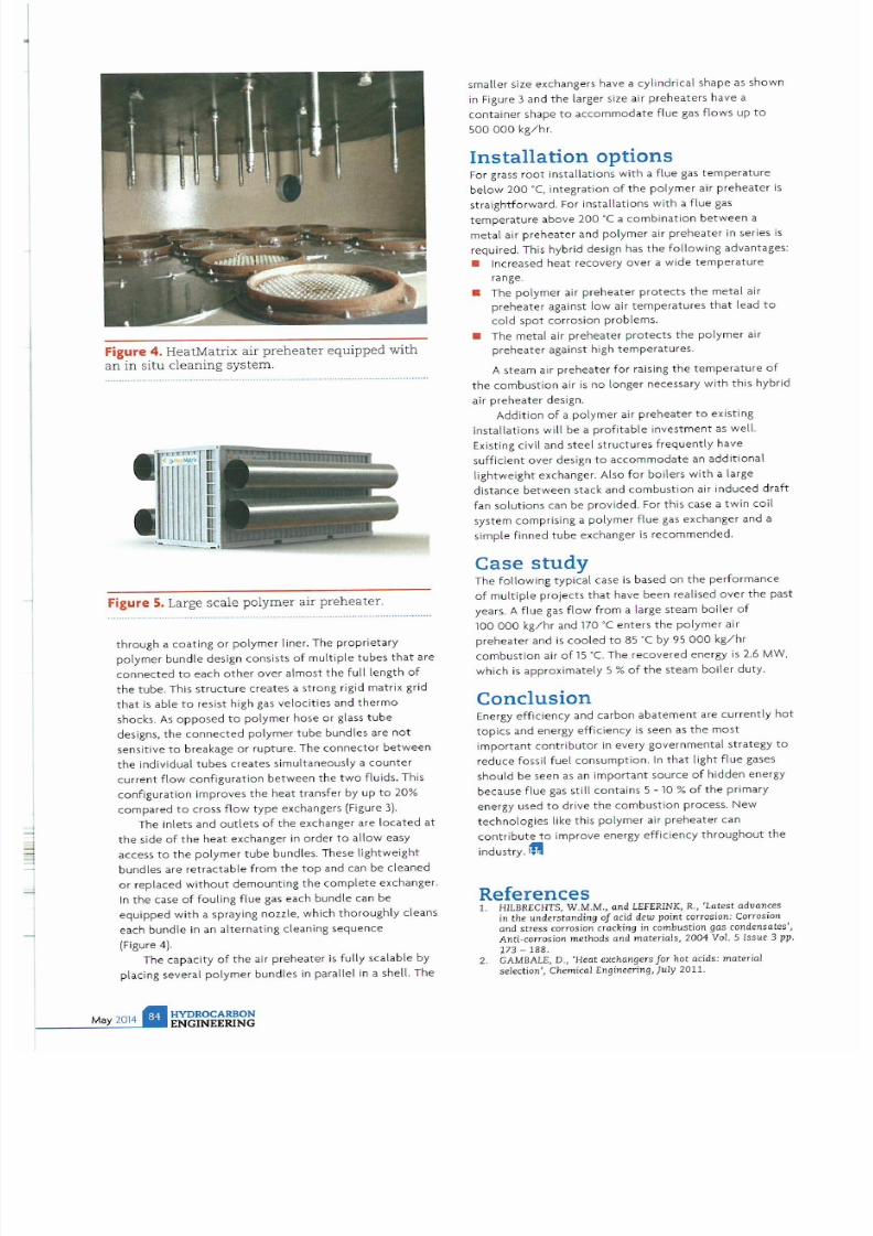
7/21/2019 Hydrocarbon Engineering Mayo 2014 Vol 19 05
http://slidepdf.com/reader/full/hydrocarbon-engineering-mayo-2014-vol-19-05 81/107
Figure 4. HeatMatrix air preheater equipped with
an in situ cleaning system.
Figure
5.
Large scale polymer air preheater.
th rough a coating or polymer liner. The propr ietary
polymer bundle design consists
of
multiple
tubes that are
connected to each
other
over almost the full length of
the tube. This structure creates a strong rigid matrix grid
that is
able
to resist high gas velocities
and
thermo
shocks. As
opposed
to polymer hose or glass tube
designs, the connected polymer tube bundles are not
sensitive
to
breakage
or
rupture
. The
connector between
the
individual
tubes creates simultaneously a
counter
current flow configuration
between
the two fluids. This
configuration
improves the heat
transfer by up to 20
compared to cross
flow
type exchangers
(Figure
3 .
The inlets
and
outlets
of the exchanger are located at
the
side
of the heat exchanger
in
order to allow
easy
access to
the
polymer
tube bundles.
These lightweight
bundles are
retractable
from
the top and
can be cleaned
or replaced
without
demounting
the complete exchanger.
In the
case of
fouling
flue gas each bundle can be
eqUipped
with
a spraying nozzle, which
thoroughly cleans
each bundle
in
an
alternating
cleaning
sequence
(Figure 4).
The
capacity
of the air preheater is fully
scalable
by
placing
severa
l polyme r
bundles
in parallel in a shel l.
The
HYDROCARBON
ENGINEERING
smaller
size
exchangers have
a cylindrical
shape
as
shown
in
Figure 3
and
the larger size air preheaters
have
a
conta iner shape to accommodate flue gas flows
up
to
500000 kg/hr
Installation options
For grass root
installations
with
a flue gas temperature
below
200
·C,
integration of
the
polymer
air preheater
is
straightforward.
For
installations with
a
flue
gas
temperature
above
200
·C
a
combination
between a
metal
air preheater
and
po l
ymer
air preheater in
series is
required.
This hybrid
design has
the
following advantages:
•
Increased
heat
recovery over
a
wide
temperature
range.
• The
polymer
air preheater protects the
metal
air
preheater against low air temperatures that lead
to
cold
spot
corrosion problems.
•
The metal
air preheater protects the
polymer
air
preheater against high temperatures.
A
steam
air
preheater
for
raising
the
temperature
of
the combustion air is
no
longer
necessary
with this hybrid
air
preheater
design.
Addition of
a
polyme
r air
preheate
r
to
existing
installations
will
be
a
profitable investment
as wetl.
Existing civil
and
steel structures frequently have
sufficient
over design to
accommodate an
add
i
tional
lightweight exchanger.
Also
for boilers with
a large
distance
between
stack and combustion
air
induced draft
fan
solutions can be prov
i
ded.
For
this case
a
twin coil
system comprising
a
polymer flue
gas
exchanger
and
a
simple
finned
tube exchanger is recommended.
Case
study
The
follOWing typical
case
is
based
on
the performance
of multiple projects that have been
realised
over the past
years. A flue gas flow from a large
steam boiler of
100000 kg/hr and
170
' C enters
the polymer
air
preheater
and is
cooled
to
85 ·C
by
95 000
kg/hr
combustion air of
15
°C. The
recovered energy is
2.6
MW
,
which is
approximately
5
of
the steam boiler
duty.
Conclusion
Energy effiCiency
and carbon abatement are currently
hot
topics
and
energy efficiency is seen as the most
important contributor
in
every
governmental strategy
to
reduce fossil fuel consumption. In that light
flue
gases
should be seen
as
an important source of hidden energy
because
flue gas still
contains
5 -
10 of
the primary
energy used
to drive the combustion pro
cess.
New
technologies
like
this polymer
air
preheater can
contribute to
improve
energy
efficiency
throughout the
industry
. i 'I
References
1.
HILBRECHTS,
W.M.M., and
LEFERINK, R., Latest advanc
es
in the understanding of acid dew point
corrosion
Corrosion
and
stress
corrosion
cracking
in combustion gas
condensates ,
Anti-corrosion methods and materials, 2004
VoL
5 Issue 3 pp.
173 - 188.
2. GAMBALE, 0
., Heat
exchangers for hot acids: material
selection', Chemical Engineering, July 2011.

7/21/2019 Hydrocarbon Engineering Mayo 2014 Vol 19 05
http://slidepdf.com/reader/full/hydrocarbon-engineering-mayo-2014-vol-19-05 82/107
•
ANTG GURMAN
BARTEC RUS GMBH
RUSSIA DISCUSSES
TEMPERATURE
MANAGEMENT IN
CRUDE OIL

7/21/2019 Hydrocarbon Engineering Mayo 2014 Vol 19 05
http://slidepdf.com/reader/full/hydrocarbon-engineering-mayo-2014-vol-19-05 83/107
Application
In
order to
remain on a state of
the
art level of technology
IPP
permanently invests in the modernisation of
the
crude oil
terminaL Furthermore
the
company aims for a consequent
increase of the tank farm capacity
and reco
nstruction of the
fuel pipeline
in
accordance with European ecological standards
of safety_ In this context BARTEC succeeded in convincing IPP
of its technical know how
and
competence The safety
technology provider recei ved the
order fo
r the engineeri
ng
manufacturing and supply
of
trace heating for the plant. The
implemented cable was the self limiting parallel heating cable
PSB as
well
as the self limiting parallel heating cable HSB. PSB is
used for the heating of the fire
figh
t
ing
water lines and the
technological water lines
to
avoid the pipes gett ing frozen. HSB
is
used for the heating of crude oil and ship fuel. The target here
is to
maintain the technological temperature. The convincing
advantage of these two kinds
of
cables
is
their ab ility
to
be used
in exploSive atmospheres without any temperature limiter.
Consequently, costs for further components could be sav
ed
.
More than
22
000
m
of
the
cables are used in total. They
are
divided into 870 heating sections.
Installation
The PSB and the HSB heating cables have a
temperature
dependant resistive element between
two
parallel copper
conductors that regulates and
lim
its the heat output of
the
heating cable according
to
the ambient temperature.This
output
regulation
is
carried out automatically along the
ent
ire
length of the heating cable according to the prevailing ambient
temperature.
Ac:. the
ambient temperature rises,
the
heat output
of
the
cable
is
reduced. This self limiting property prevents
Figure 1. The self limiting heating cables can be
used without any limiter in explosive atmospheres.
HYDROCARBON
ENGINEERING
overheating even when
the
cables are overlapped. A
temperature limiter
is
not required, not even in explOSion
hazardous zones as in Novorossi jsk crude oil terminal.
Thanks
to the
parallel power supply the heating cable can
be
cut
to any required length. Th is feature considerably
simplifies pr
oject
planning and installation. The heating cable is
cut and
te
rminat
ed in
accordance with the local requirements
directly on the construction site. In cases where the cable may
become damaged, it
is
not
necessary
to
replace the whole
circuit but only the
affected
part. The
protective outer
jacket of
either fluor polymer or polyolefin protects the inner copper
braiding from corrosion and chemical attack. The
copper
braiding serves as an earth conductor in accordance with
VDE
0100 and also increases the mechanical stability
of
the
cable. Under the protec tive braiding are
two
synthetiC jackets
proViding electrical insulation. The inner of the two jackets
is
thermally fused
to
the heat ing element (bonded jacket).
Because the related equipment
to
the heating pipes also
has
to
be certified for applications in
Ex
areas, the PLEXO
connectio
n system,
the
connection
technology
heat
shrink
Ex
as well as cold applied sets have been used
to connect
the
heating cables. PLEXO, the first plug in connection system for
heating cables used in potentially explOSive atmospheres, of fers
substantial reductions
in
installation time and expense.
Ma i
ntenance
work for future modifications of
the
heating
ci
rcuit can
be
carried out more effiCiently. The connection
system
is
well suited for self limiting parallel heating cables.
The heat ing cable and power supply connection cable
are
connected
via safe spring creating the requ isi te pressure,
eliminrlting any need for unravelling or twisting. A sophisticated
sealing system offers safe and
rel
iable protection against
adverse weather
co
nditions. The flexibility
of the
system allows
direct
connection
of the heating cable to a supply cable or an
Ex junction box. Two similar heating cables can be joined to
each other
by means of a splice plug
and socket
connection
sleeve. The heating
tape
remote end termination can be
eqUipped with plug in contacts for future extensions
of
the
heating Ci rcuit.
The
connection
technology heat shrink Ex
is
a reliable
technology for connecting heating cables. The principle is easy.
After st ripping the heating tape, insulat ion tubes are shrunk over
the supply lines and the twisted protective braiding and wire
end sleeves are put on . As a basic rule, the heating cable
is
connected
to
terminals in an enclosure
that
has increased
safety
or
fiameproof encapsulation
protection
class. The
heating circuit
end is
also closed with shrinkable tubes. For
direct connection of the se lf limiting heating cables into the
junction box cold applied sets have been used. The easy
assemb
li
ng with silicone cold applied technology offers
connection and termination in one set. It
is
a small place saving
and economic solution.
93
temperature sensors as well as seven control and
distribution panels we re also part
of
the application . The
system to control the heat t racing was deSigned by
BARTEC
Russia and
is
based on t he Russian controllers OWEN, fully
featured programmable devices for au tomation tasks. The
software for
the
touch
screens
on the
control panels was a
customer specific
development
by
BARTEC
Russia.
By competently handling this project, BARTEC succeeded in
laying the foundations for further cooperation. i I

7/21/2019 Hydrocarbon Engineering Mayo 2014 Vol 19 05
http://slidepdf.com/reader/full/hydrocarbon-engineering-mayo-2014-vol-19-05 84/107
C
ndition
monitoring
of
rotating equipment is a well
established practice
in
many hyd rocarbon processing
[ants wi t
h
a goa l
to
detect . analyse and correct
machinery faults
to
optimise maintenance intervals,
extend production sc hedules and avoid
un
planned d w l l l il ne.
Critical machinery turbines, compressor
s
l
ar
ge
motors)
is
normally equipped with online condition monitoring and
protection systems
but the
balance of plant equipment motors,
pumps, and fans generally is not. This
machine
category
represents well over half
of the
rotating machine
pop
ulati
on
and
consumes a significant
pe
rcentage of a maintenance budget.
ften
, these machines are monitored with portable data
collectors as, hi storically, it has been either impractic
al or
uneconomical
to
insta ll and maintain a permanently wired
system. However a new breed of wireless condition
mon ito
ring
systems
proposes to
bridge
the
gap between
the cost
of
wired and portable systems.
Wireless condition
monitoring
developments
The promise of ubiquitous, low cost
sensors
op e
rating over a plant wide
wireless network has fuelled massive
investments by leading technology companies in
va ous wireless applications. As a result, developments in
industrial wi reless technologies are happening at a frenetic pace.
Wireless condition monitoring devices have been available for several
years, however wid
esp r
ead
market adoption has
not
taken place
due to
technical issues including proprietary protocols) and
cost
barrier
s.
With
recent advances
in
networking, rad
ios
processors, sensors, and power
sources
it is
now possible
to
overcome these obstacles.
Cond
iti
on monitoring using dynam
ic data e.g.
vibration) makes unique
demands on wi reless sensors, networks and associated components, such
as high bandwidth, good dynamic range, low noise, higher level processing
capabilities and
the
ability to capture data
at
the right time. hen
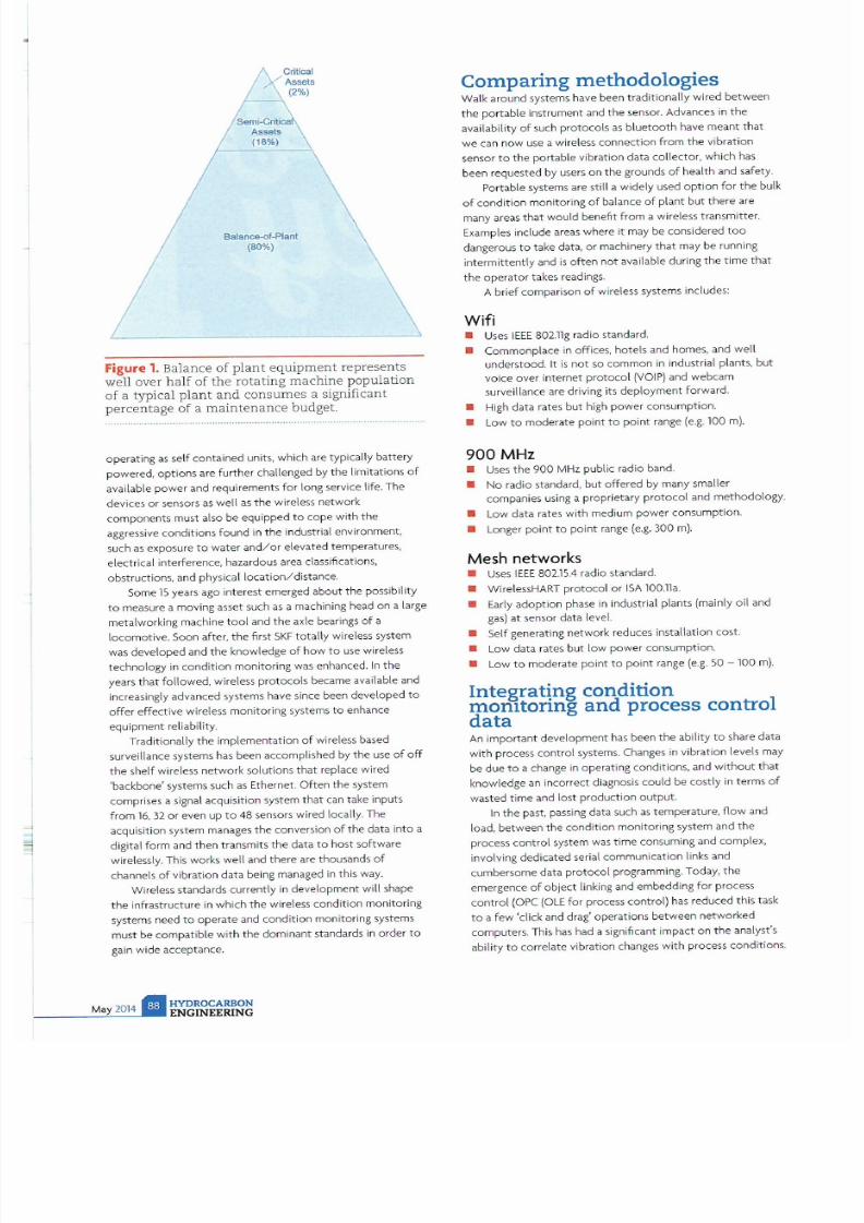
7/21/2019 Hydrocarbon Engineering Mayo 2014 Vol 19 05
http://slidepdf.com/reader/full/hydrocarbon-engineering-mayo-2014-vol-19-05 85/107
Ba lance..af-Plant
80
)
Figure 1. Balance
of plant equipment
represents
well over half of the rotating machine population
of a typical plant and consumes a significant
percentage of a maintenance budget.
operating as self conta ined units, which are typically battery
powered, options are further challenged by the limitationsof
available
power
and requirements f
or
long service life. The
devices or sensors as well as the wireless network
components must also be equipped
to
cope wi
th
the
agg ressive conditions found in the industrial environment,
such as exposure
to
water and/or elevated temperatures,
electrical interference, hazardous area classifications,
obstructions, and physical location/distance
Some lS years ago interest emerged
about the
possibi lity
to
measure a moving
as
set such
as
a machining head on a large
metalworking machine
tool
and the axle bearings of a
locomotive. Soon after, the first
SKF
totally wireless system
was
developed
and the knowledge of how to use wireless
technology
in
condition monitoring was enhanced.
In
the
years that followed, wireless
protocols
became available and
increaSingly advanced systems have since been
developed
to
offer e ffective wireless monitoring systems to
enhance
equipme nt reliability.
Traditionally
the
implementation
of
wireless based
surveillance systems has been accomplished by the u
se
of off
the shelf wi reless network solutions that replace wired
backbone systems such as Ethernet. Often the system
comprises a signal acquisition system that can take inputs
from 16,
32
or even up to 48 sensors wired locally. The
acquisition system manages the conversion of the data into a
digital fo rm and then transmits the data to host software
wirelessly. This works well and there are thousands of
channels of vibration data being managed in this way.
Wireless standards currently
in deve lopment will shape
the infrastructure in which the wireless condition monitoring
systems need
to
operate
and conditio n monitoring systems
must
be
compatible with the dominant standards
in order
to
gain wide acceptance.
HYD OC RBON
ENGINEERING
Comparing
methodologies
Walk around systems have been traditionally wired between
the portable instrument and the sensor. Advances in the
availability of such protoco ls as bluetooth have meant that
we can n ow use a wireless connection from the vibration
sensor to the portable vibration data collecto r, which has
been requested by users on the grounds of health and safety.
Portable systems are still a Widely used option for the bulk
of condition monitoring of balance of plant but there are
many areas that would benefit from a wireless transmitter.
Examples include areas where it may
be
considered
too
dangerous
to
take data, or machinery that may be running
intermittently and is
often
not available during the
time
that
the
operator takes readings.
A brief comparison of wireless systems includes:
Wifi
• Uses IEEE 802.11g radio standa rd.
• Commonplace
in
offices, hotels and homes, and well
understood.
It
is
not
so
com
mon
in
industrial plants,
but
voice over internet protocol
VOIP)
and webcam
surveillance are driving its deployment forward.
• High data rates but high power consumption.
• Low to moderate point to point range e.g. 100
m).
9 MHz
• Uses the 900 MHz public radio band.
• No radio standard, but offered by many smaller
companies using a proprietary
protocol
and methodology.
• Low data rates with medium
power
consumption.
• Longer point to point range e.g. 300
m).
Mesh networks
• Uses
IEEE
802.15.4 radio standa rd.
• WirelessHART protocol or ISA 100.11a.
•
Early adoption
phase
in
industrial plants (mainly oil and
gas)
at
sensor data level.
• Self generating network reduces installation cost.
•
Low
data rates
but
low
power
consumption.
• Low to moderate point to point range e.g. 50 - 100
m).
Integrating condition
momtoring
and
process
control
data
An
important
development
has been
the
ability
to
share data
with process contro l systems. Changes in vibration levels may
be
due to a change in operating conditions, and without that
knowledge an incorrect diagnosis could be costly in terms of
wasted time and lost production output
In the past, passing data such as temperature, flow and
load,
between
the
condition monitoring system and
the
process control system was time consuming and complex,
involVing dedicated serial communication links and
cumbersome data protocol programming. Today, the
emergence of
object
linking and embedding for process
control OPC OLE for process control) has redu
ced
this task
to
a few click and drag operations
between
networked
computers. This has had a Significant impact on the analyst s
ability to correlate vibration changes with pr
ocess
conditions .

7/21/2019 Hydrocarbon Engineering Mayo 2014 Vol 19 05
http://slidepdf.com/reader/full/hydrocarbon-engineering-mayo-2014-vol-19-05 86/107
A solution
for
hazardous envir
onments
The potential to improve efficiency through
condition
monitoring
has
driven the development of a new wireless
solution from
SKF
The SKF Wireless Machine Condition
Sensor is ideal for monitoring machine components
in
locations that are difficult to access, and uses its wireless
technology
to
solve a series
of
issues that could not be
addressed
with wired systems. CrUCially
the
product has
ATEX
Zone 0 certification, which means that
it can
be used in
hazardous environments, and has significant benefits in many
app
lications
throughout the
petrochemical, oil and gas
sectors.
The SKF Wireless Machine Condition Sensor collects data
on three key machine conditions: temperature (indicative of
lubrication
issues
, increased friction, rubbing. etc.); overall
machine condition (vibrations caused by misalignment.
imbalance. mechanical looseness. etc.); and rol ling element
bearing condition (allows damage
detection
and diagnosis of
source
as
ball/
roller
. cage. inner
or
outer raceway).
A rough estimate for the cost
of
installation
of
online
sensors
in
onshore applications
can
be
as
high
as
15 times the
cost of the accelerometer and for offshore installations it
can
be higher than 20 - 30 times the cost of the accelerometer.
The use of a wireless device could equate to
an
approximate
saving
of
approximately USS
1500
/ measurement point.
With this new technology,
users
can benefit
from
an
improved maintenance programme, reduced maintenance
cos
ts
reduced installation costs and enhanced employee and
machine safety. The sensor also
of
fers
compatibility with
the
SKF @ptitude onitoring Suite, a comprehensive software
11
.£ . 1
LTH<5'1.COM
CC; ; ;
Fertilizer
j lndustr
ia l IOil I
Ga
s I Metallurgy
China International
T
o
Sulphur Sulphuric Acid
C\I
4th International Conference Exhibition
Sponsors:
V
CHEMTR DE
GIOtlS
..:leveo
r - - - - - - - - - - - - - - - - - - - - - - -
I
S K F C W I > I L d ~ 1
W ' s a 5 e l 1 s o r C l e ¥ i c e M ~ I C I f h o ,
Figure 2. Mesh networks can relay data from point
to point and to the gateway.
suit
that integrates data fr
om
a wide range of SKF portable
and
online data acquisition devices.
SKF
Wireless Machine Condition Sensors communicate with
each
other,
and with
a wireless gateway, creating a mesh network
This
type of network
and
communication protocol is ideal for
monitoring rotating machinery because it
can
function in areas
where traditional WiFi communications are not present.
Official publications
la FERllUZERWEEK
Media partners
-
NG INEERING

7/21/2019 Hydrocarbon Engineering Mayo 2014 Vol 19 05
http://slidepdf.com/reader/full/hydrocarbon-engineering-mayo-2014-vol-19-05 87/107
Figure 4. The
SKF
Wireless
Ma
chine Condition
Se
nsor collects
d t
on
three
key machine
conditions: tempe
r ture
, overall machine
co ndition , and rolling element bearing, and
h s
ATEX Zone 0 certific ation.
Communicating via a
mesh
network
Communicationcapabilities of the SKF device include
relaying
data
from one node to another, relaying data back to
the
gatew
ay
, and
receiving automated commands from the Wireless Sensor Device
Manager
software that
initi
ates the measurement
and
processing
circuits
to
take data and transmit
it
back over the
network.
If a
node is unable
to
receive signals directly from the WirelessHART
gateway. it will instead send and receive its data through a nearby
node that ca n
pass
the data to and from the gateway, ultimately
creating the mesh network.
Once
data
is collected the WirelessHART gateway
o
mmunicates with the Wireless Sensor Device Manager software
supplied by
SKF.
Data can then
be
automatically exported into
SKFs
comprehensive diagnostic and analytic software package,
where a maintenance manager can ana
ly
se the data and determine
a course of action. In
pa
rallel, the WirelessHART gateway can
al
so
send applicable data directly to the process control system
for
vis
ual
isation and trending by operators.
Th is is the first SKF product to use the Wireless HART
communication protocol which was unanimously approved by the
Intemational Electrotechnic
al
Commission (lEe)
in 2010
,and to
prOVide
a battery powered wireless condition monitoring solu
ti
on
suitable
for
use
in
an
ATEX Zone °
nvironment. The mesh
network and excellent battery management
gives
the device a long
ope rating life,
making
it a practical alternative to
wi
red online
systems for monitoring balance of plant machinery.
Case study
Anewly
built
refin
ery
in
Asia Pacific with
an annual
capacity of
2
million tpy
275
000
bpd)
installed the
SKF
Wireless Machine
Condi t ion Sensor. The single train plant is designed to process high
acid
heavy
offshore crude.
All
critical
machinery
was fitted
wi
th protection systems
(API-670) by the EPC but there was no onHne machinery condition
monitoring
system.
The plant had no portable
vibration analyser
programme
in
pl
ace;
instead, equipment was moni tored
using
biweekly operator rounds collecting vibration
and
other data using
simple hand held devices and industrial PDAs.
After several unplanned outages on pumps, a reliability centred
maintenance (RCM) study determined the need to add a
surveillance system on all pumps above 500 kW.
Requ
irement
was
for more frequent data collection of vibration and temperature at
pump bearing locations.
The sol ution was to provide a sensor system for machi ne
condition monitoring that could monitor plant areas uneconomical
to cover by wired or walk around
sol
uti
ons,
avoid cable trays and
wi
r
ing,
reduce installation t ime, and minimise project engineering
and documentation. Deploying a network of wireless fie ld sensors
using WirelessHART protoco l engineers achieved open and
interoperable communications, while the mesh network offered
the capability to naVigate data around obstacles and cover
dis
tances greater than the devices innate
ra
nge.
Within three months of installation, the ex tended monitoring
proVided by the wireless sensor network
found
a pump problem
that would
have
gone undetected by the previous portable
prog
ramme: extremely high but intermittent vibrat ions were
recorded at the pump bearings. These vibrations we
re
most likely
process induced, and had
led
to bearing damage that
was
clearly
identified in the spectra sent
back
f
rom
the wireless sensor.
The
maintenance team
was
able to
plan
a bearing change at the next
convenient window, and the plant avoided
an
unexpected failure
on this important pump. The downtime cost saving of th
is
incident
alone
justified
the investment in the wireless sensor
network.
Conclusion
Wireless systems will change the way we approach machine
cond
ition
parameter data collection. Wireless sensors w
ill
no
doubt result
in
much more data
being
acquired and therefore there
will be
an
increasing need to analyse and store this data. Further
data interpretation using decision support systems and data
reduction methods will need to be developed and deployed.
Ease of deployment of
wi
reless systems connected to process
cont rol
sys
tems will be driven by users, not by suppliers of
technology solutions, and performance monitoring
will
become
more closely integrated to cond
iti
on monitoring. Using
manufacturing and control system information
will
enhance the
way
vibration data
is
analysed.
Thi
s
will
allow maintenance
personnel to determine the cause of the fai lure of a machine or
system component not just change a defective component
without knoWing why it fai led. Also, fully integrated embedded
sensors using standard industrial protocols to sha re data,
will
be
offered by which
will
bring the benefit of low installation
costs.
The stage
ha
s passed when early adopters installed
simple
systems on an experimental bas is. For
wi re less
condition
monitoring,
thi
s
is
the end of the
beginni
ng. What engineers are
looking
for
is
a system that
is
simple to
install
and ea
sy
to configure
and uses existing knowledge and decision support systems to
manage the configuration and interpretation of the data.
This will
give real value to plant managers in manag ing plant uptime and
effiCiency. i' 'II

7/21/2019 Hydrocarbon Engineering Mayo 2014 Vol 19 05
http://slidepdf.com/reader/full/hydrocarbon-engineering-mayo-2014-vol-19-05 88/107
t
GLOB L
M IN
EN NCE
HYDROC RBON
NGIN RING
provides an
overview of maintenance
projects
undertaken around
the world
over the past 2 months

7/21/2019 Hydrocarbon Engineering Mayo 2014 Vol 19 05
http://slidepdf.com/reader/full/hydrocarbon-engineering-mayo-2014-vol-19-05 89/107
AFRICA
AFRICA
(ihafHi I
It was anno unced at the end of Febr uary
2014
tha t PetroSaudi
Internatio
nal and Ghana are looki
ng to
sign a
jOint
v
en
tu re for
the revival of the Tema Oil Refinery . The plant has been shut
on numerous occasions over
th
e pas t fou r years due t o lack of
fu nds.
Libya
In
S
epte
m
be
r 20
13
.
i
bya's National Oil C
orpor
ation
announced maintenance at its Zawiya refinery. The length of
th e ma i
nt
e nan
ce
proje
ct
was not disclosed but
one
unit was
part of the project . The plant
ha
s a processing capacity of
12
0000
bpd.
Nigeria
Kaduna Petrochemical Company.
towar
ds t he
end
of last year
propo
sed a main
te
nance turnar
ound
th at
will Increase
annual
income to N 1trill ion . The mai ntenance will be carried out by
t he origina l builders of the pl ant, Chiyota of Japi ln . The last
maintena nce work was done in 2005 and th
is
new project has
been approved by the Federal Government.
SQuth .Af.riC9..
In the middle of last year. National Oil Company Pe
tr o
SA
ann ou
nc ed
th
at in
an effo rt to improve e
ffi
ciency it was going
to suspend op erations
at
the Mossel
Bay
facilities for 37 days
fo r a planned
statuto
ry maintenance shu
tdown
. The
shutdown
was scheduled
to
start
on
nn
September and affect t he
Mo
ssel
Bay gas
to
liquids
GTL)
refinery and offshore FA
platfo rm. During the 37
day
perIod, PetroSA ce a
se
d all
product ion act ivities. Products that were not availa
bl
e during
the maintenance pe riod included liquefied pe troleum gas,
propane
. CO
2
, l
iq
uid nitrogen and liquid oxygen.
Petr
oS
A made
con
t ingency p lans for the ava
ila
bility of
ot
her products such as diesel and petrol for the South ern
Cape area.
Pe
troSA also informed its other customers in a
t ime ly manner
abo
ut the shutdow n and encouraged t hem to
make altern ative sup p ly a rrangements.
W C SE
SI
U Y
In
July
2013
Engen Pet roleum, the African downstream
petroleum multinat ional , announced th at It had plans to
sig
ni
ficantly inc rease i
ts
supply
capac
Ity to
southern
African
cou
nt ries. after it acquired seven In
count
ry operations from
co
mpetitor
Chevron in
the
region and
the
Indian
Ocean
Islands. The
company
is currently undergoing firs t
phase
revamp work
on
Bei
ra Terminal. an Import and
storage
faCility in
th..e
Port of Belra , Mozambique. When comp lete .
the terminal will be able to supply Mozambi
que
. Zimbabwe.
Zambia. Botswana
and
southern ORe.
Strategy and investment
The
depot
forms part of the Mozamblcan compotent of the
acqui i tion and predated all ot hers. It was aimed at
strategICally bo osting s ecuri ty of supply in the region . given
Engen's increasing market share
in
southern and Sub-Saharan
Afr
ica . The depot
requ
ired a significant cap ital Investment to
overhaul and extend and the te rminal was
no
t operational
for a conSiderable
time
. The pr
oject
involved
the
cleaning
and
safe dismant
li
ng of
redundant pip
ing
and
two unusable
tan
ks
; rev
amp
ing of
three
tanks
and
admln offices;
and
Installation of new ta nks .
road
tanker loading faciliti es.
GLOBAL
import and export piping. a firefight i
ng
system and security
system.
Phased supply and progress
The first phase of
proceed
ings was a imed
at
readying
the
fadilt y for impor t and supply of
petr
o l
and
diesel in
Mozambique {20
of
the olume requir
ement
, and Zimbabwe
(80 ). The wo rk was done via the ex isting pipeline to Ma sasa
Depot in Harare. The
term
Inal's designed capacity of
18 million Itrs of diesel and 7 million ltrs of
petrol
is
expected
to
be
sufficient for this purpose.
Once
phase one projected products demands were
achieved, Engen had plans for second phase construction
which was planned to involve Increasing tank and
road
loading
capacity. and
the
const ruct ion of a ne w ra il loading facility to
cater for Engen's other southern African sister companies.
In July of last year the project was on track with the
target of reachi
ng
9 mechan ical completion by the
end
of
December
2013
. The company planned
to
have
the depot
fully operational in the first
quarter
of 2014
and
hopes to
e c o m
the leading Sub-Saharan African oil company by
2016.
\ A N T l l ~ £
REVEW
I
MBY

7/21/2019 Hydrocarbon Engineering Mayo 2014 Vol 19 05
http://slidepdf.com/reader/full/hydrocarbon-engineering-mayo-2014-vol-19-05 90/107
The shutdown was aimed
at
ensuring
the
integrity
of
equ i
pment
and systems
at
the
two
facilites, in compliance
with the Mine Health and Safety Act and the Occupational
Health and Safety Act. PetroSA's operating permit also
requ ired
that
the company undergo routine statutory
shutdowns n
order to
inspect and repaIr critical
equipment in order to ensure their integrity. Over the
years. PetroSA has s
et
a proud record
of
executtng
shutdowns within budget and safely. The four yearly
scheduled shutdown is expected to
involve a combined
workforce
of
app roximately
4
. The number
is
inclusive
FRIC
SI ND
nfEP CIFIC
of
temporary employees sourced from the Mosse l
Bay
community. During
the
2009 shutdown, 80
of the total
workforce was made up of people from the Mossel
Ba
y
area.
In
May of
last year. the SAPREF refinery shut
one of
its
secondary un its for planned ma intenance which was
anticipated
to
take three weeks. The Durban refinery shut
i
ts vis
breaker unit which is used
to
reduce viscosity when
distill i
ng
crude oil. The SAPREF refinery is jOintly
owned
by
Shell and
BP
.
SI
ND
DIE P ClRC
4 l J s q j J l j ~
In
November
last year,
ASS signed a
long
term
service
agreement
with
QGCm
a wholly owned subsi
diary
of
SG
Group. to provide
planned and unplanned maIntenance for the up and mid stream
facilities at Queensland Curtis LNG (QCLNq The project, located
in
Queensland. Australia, is the world s first to convert gas from
coal seam
into
LNG
.
The contract value is AUSS 33 million over four years. booked
in the third and fourth quarter of 2013, with potenti
al
for extending
the
service
term
up to
a period
of
10
years.
ASS is
to
provide
comprehensive
se/Vices
including
an
onsite tream
to
maintain
ABS s
Extended Automation System 800 A Integrated Control and Safety
System. The contract also covers spare parts management for
QCLNG s
upstream collection and transportation
facility as well as
for the midstream liquefaction and export facility.
C l 1 i n ~
ASS signed a
long
term Preventative Service
'
agreement with
China
LNG Shi
pp
i
ng
International Co . Lld (Cl5ICO) in May last year, to
proVide
maintenance services
to
all
ASS
equipment onboard
of
its
sixLNG
vessel
s In the next five years.
The
new service agreement helps
CLSICO
with optimised
vessels
performanceat a predicted
minimum
level of budget.
ASS
will provide annual site survey and on call services
to
the six vessels
covered by the agreement, as well as dry dock selVice every
2S
year
s. The
scope of the agreement covers preventitive
maintenance onboard. power generation plant and mechanical and
electrical systems.4
I o d i ~
Mid 2013,
Alfa
Laval won an order to supply
Alfa
Laval Packinox heat
exchangers
to
a petrochemical p ant in Ind ia.The order was booked
In the Process Industry segment with a
value
of
SEK 185
million.
Deliveries
were scheduled for 2013 and 2014.
Last November Bharat Petroleum Co rp. Ltd. (BPCL) bagan partially
shutti
ng
secondary units at three of its refineries for ma intenance.
Work on the
Kochi
refinery began in
mid November
. This
was
foHowed
by
the
Mumbai
refinery in December and the
Numalrgarh
refinery
in January of
this
year.
Each
shutdown was scheduled to
last 25 - 30 days.
At
the start of this year BPCL made an announcement that
it
was to
shut a crude unit at the
Mumbal refinery
for approximately
two weeks between Apnl and May as part
of
the 40 day
maintenance plan at the facility for the catalytic cracker unit.
Heurtey Petrochem announced the
Signature
of a
€
31 million
contract in the petrochemical sector with Reliance
Industries limited in May last year.
The
contract concerned the
turnkey
delivery of
six furnaces
for a petrochemical complex within
the
Jamnagar refinery
in Gujarat
Sate,
West India.The delivery of
the equipment is scheduled for January
2015
.
Reliance Industries
announced n
March
of
this
year that
it was to
shut one of the four crude distillation units at the
Jamnagar refinery
for ma intenance.
The
work was scheduled
to
begin on 20
th
March
and was expected
to
last three and a half
weeks.
The company also
planned to use
the scheduled shutdown to
repl
ace catalyst
in
the
plant s vacuum gas
oil
and naphtha hydrotreater.
J ~ p a n
Turraround \york at the
Nansei Sekiyu refinery will
be carried
out this year from 3
rd
February to r March. The main objective
of the shutdown and mamtenance routine is to overhaul and
GLOB L
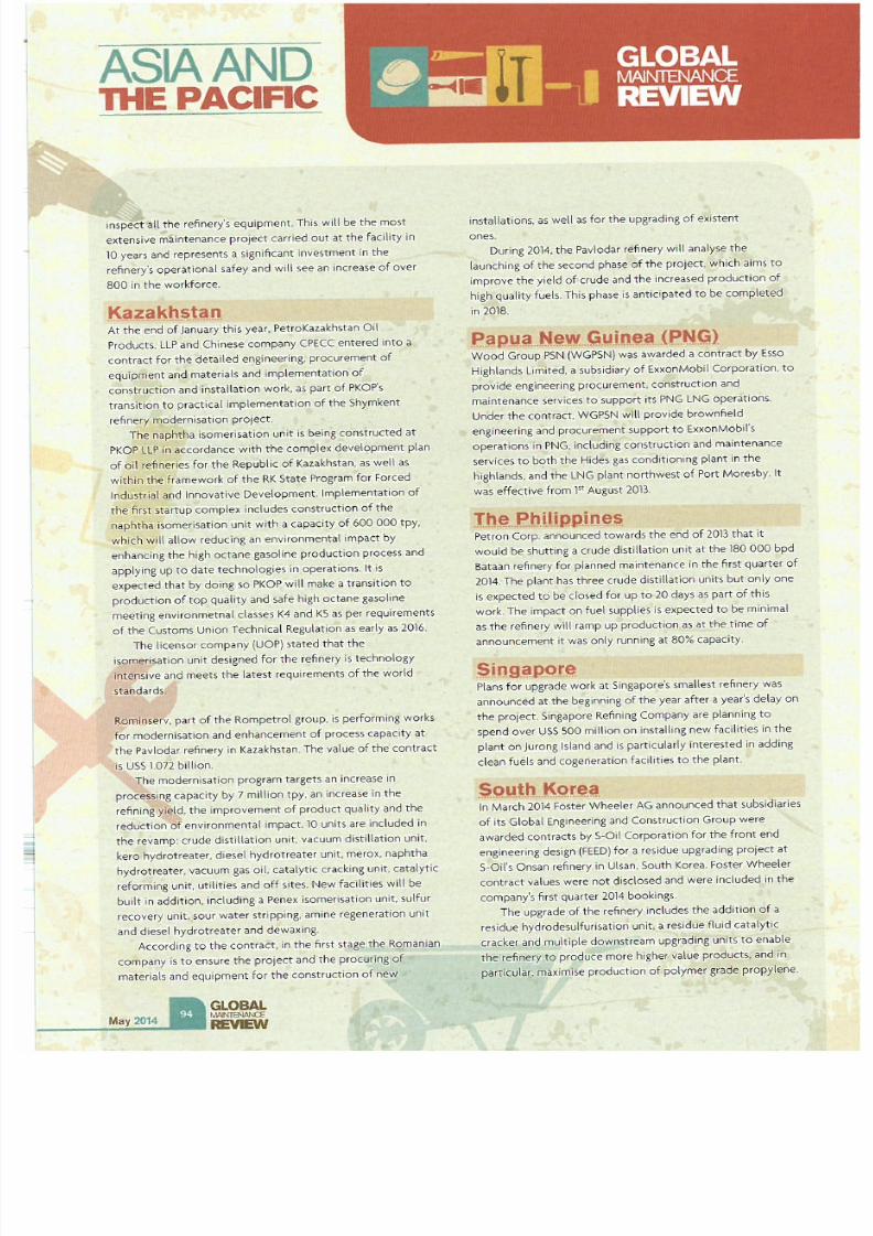
7/21/2019 Hydrocarbon Engineering Mayo 2014 Vol 19 05
http://slidepdf.com/reader/full/hydrocarbon-engineering-mayo-2014-vol-19-05 91/107
ASIA AND
THE PACIFIC
Inspect a
l the
refinery s equi
p nt
.
This will be
the most
extensive maintenance project carried out at the facility in
10 years and
represents
a significant investment in the
refinery's operat ional safey and will see an increase of over
8 in the workforce.
t < a z a k h ~ t a n
At
the
end
of
January t his yea r. PetroKazakhstan Oil
Products. LLP and Chinese company (PECC entered mto a
contract for the detai led engineering, procurement of
equipment and
materials
and
i
mplementa
t ion
of
construction and installation work, as part of PKOP's
transition to pract ical implementation of the Shymkent
refinery modernisation project.
The naphtha isomerisation unit is being constructed
at
PKOP LLP tn
accordance
with the complex
development
plan
of oil refineries for the Repub
li
c of Kazakhstan, as well as
within
the
framework of
the R State
Program for Forced
Ind
ustrial and Innovative
Development
. Implementation of
the first startup
complex
includes
construction
of the
naphtha
isomerisation unit with u capacity of 6 tpy .
which will allow reducing
an
environmental impact by
enhancing the high
octane
gasoline
production
pr
ocess
and
applying up to date technologies in operations . It
is
expected that by doing so PKOP will make a transition to
production of top quality
and
safe high octane gasoline
meeting
en
vi ronmetnal classes
K4 and K5
as per requirements
of the Customs Union Technical Regu lation as ea rly as 2016 .
The licensor company (UOP) stated that the
isomerisation unit designed for the refinery is technology
in tenSive and meets the latest requirements of the world
standards.
Rominserv. part of the Rompetro\ group. is performing wo rks
for modernisation and enhancement of process capacity at
the
Pavlodar refinery
in
Kazakhstan. The value
of the
contract
is USS
1.072
billion.
The modernisation program targets an inc rease In
processing capacity by 7 million tpy. an increase in the
refining yield. the i
mp
rovement of
product
quality and the
r
eduction
of
environmenta
l impact. 10 units are
In
cluded in
the
revamp:
crude
distillation unit. vacuum distillat ion unit ,
ke ro hyd rotreater, diesel
hydrotreater
unit, merox,
naphtha
hydrot
reater, vacuum gas oil,
cataly
t
ic
c racking unit, catalytic
reforming unit . utilities and off sites. New facilities wilt
be
built in addition, including a Penex isomerisation unit, sulfur
recove
ry unit. sour wat
er
stripp ing, amine regeneration unit
and
diesel hyd r
otreater and dew
ax
i
ng
.
According to the contract. In the first stage the Romanian
company
is
to ensure the project and the procuring of
materials and equipment for the construc t ion of new
GLOBAl
MI'I'ITB'WU
REVEW
installations, as well as for the upgrading of existent
ones.
During
2014
, the
Pa
vlodar refinery will analyse the
launching of the second phase of the project. which aims to
im prove the yield of crude and the increased production of
high quality fuels .
Th is
phase
is
anticipat
ed
to be
comple
t
ed
in 2018.
p ~ p u C . N e . \ N
Guine.a (PNG)
Wood Group
PSN
(WGPSN) was awar
ded
a
contract
by Esso
Highlands limited, a subsidiary
of
ExxonMobil Corpora t ion .
to
provide eng ineering
procurement
,
construction
and
mai
ntenance
services to
suppo
rt its
PNG
LNG
ope
rations.
Under
the
contract. WGPSN
w1ll pro
vide brownfield
engineering and procurement support to ExxonMobil's
operat ions in PNG, including construction and maintenance
se
rvices to both the Hides gas conditioning plant in the
highlands. and the LNG plant
northwest
of Port Moresby. It
was effect ive from pt August 2013.
The. P h i l i p ' p i n ~ s
Petron Corp. announced
towards
the end of 2013 that it
would
be
shutting a
crude
d
is
tillation unit at the 180 bpd
Bataan refinery for planned ma i
ntenance
in the first quarte r of
2014. The plant has
three
crude distillation units but only one
Is expected to be closed for up to 20 days as part of this
work . The impact on fuel supplies is expected to
be
minimal
as the refine ry will ramp up production as at the time of
announcement it was only running at 80 capacity.
S i g ~ p o r e
Plans for upgrade work at Singapore's smallest refinery was
announced at the beg in ning of the year after a year's delay on
the
project
. Singapore Refining Company are planning to
spend
over
USS
500 million on installing new facilities in the
plant
on
Ju
rong Island and
is
particularly
interested
In
add
ing
clean fuels and cogeneration facilities to the plant.
$C)l tt K . Q r ~ ~
In March 2014 Foster Wheeler
AG announced
that subsidiaries
of its Global Engineering and Construct ion Group were
awarded contracts
by S-Oil Corporatio n for the front
end
engineer ing design (FEED) for a residue upgrading project at
S-Oil's Onsan refinery in Ulsan. South Korea. Foster
Wheeler
co
ntract values were
not
disclosed and were included in the
co mpany's first quarter
2014
bookings.
The upgrade of the refinery includes the addition of a
res i
due
hydrodesulfurisat ion unit, a residue fluid ca talytic
cracker and multiple downst ream upgrading units to enable
the refinery to produce more higher val ue products. and
in
particular, maximise production of polymer grade propylene.

7/21/2019 Hydrocarbon Engineering Mayo 2014 Vol 19 05
http://slidepdf.com/reader/full/hydrocarbon-engineering-mayo-2014-vol-19-05 92/107
In
addition
to
execut
ing
the FEED. Foster Wheeler
will also prepare the tender for the engineering,
procurement and construction
(EPC)
phase, procure
long lead items. evaluate the EP( bids. and prepare a
cost estimate to support S-Oil's final investment
decision.
Sr i
In
May of last year, Sri Lanka s sole refinery faced
temporary closure for
up
to
four weeks due
to
delayed crude deliveries. This closure coincided with a
period
of
planned maintenance at the facility.
In
the
July of last year further maintenance was carried out at
the plant for a period of three days as part of a
decarbonisation period.
T ~ i w C . l
In
August last year, Formosa Petrochemical announced
its intensions to shut
two
secondary units
at
the
glob l indust:r:YH
u
.
requires l f ~ ~ l
.
= 1
.:1
+
;>
HYDROCARBON
ENGINEERING
SI ND
THE PACIFIC
Mailio refinery for planned maintenance in October
20ll.
The plant's 80
000
bpd vacuum distillation unit and
84 000 bpd residual fluid catalytic cracking unit were
the units in question and work was expected to last up
to
four weeks.
Y i ~ t l a l T
At the end of
2013
, Gazprom Neft signed an
agr
eement
with PetroVietnam
to
ac
quire a stake
in
the
Dung Quat refinery and to participate
in
the
mode
rnisation
of the
plant. The modernisation
program
will
include increaSing production
capacity at the plant from 6.5 million tpy of
processing capacity
to 12
million tpy within a year.
Improvements
to
the plant's technical efficiency
of
motor fuel production will also be undertaken
to
ensure the facility 's products meet Euro 5
standa rds.
PEINEM NN
QU I N T
For more information
vis
it ww w.peinemannequipmenl.com
or contact us al [email protected]
www .pe n t . mannt .qulpment.com

7/21/2019 Hydrocarbon Engineering Mayo 2014 Vol 19 05
http://slidepdf.com/reader/full/hydrocarbon-engineering-mayo-2014-vol-19-05 93/107
UROP
Belgil m
In
May of
2013.
TOTAL
announced that it
was
to invest
€
1billion in its Belgian refin
ing
and petrochemical complex,
n
order to boost its diesel
making
capacity and cut costs. Plant
refurbishment was scheduled to include the construction of a new
20
000 bpd hydrocracking unit to transform high sulfur heavy fuels
into low sulfur diesel and heating oil from early
2016
.
Simultaneously,TOTAL announced plans to shutdown
uncompetitive units. including a 240 000 t oil based naphtha
cracker unit and two polyethylene making units.
It illy
Sunday
2 ~ t July
2013
marked the
beginni
ng
of
the
closure
of
the
produ tio
n systems
of
the ENI Venice refinery in order
to
carry ou t
modifica tion operations which would enable production
of
biofuels as part of
the
gr
een
refinery project. During the transition
period between closure and reclamation, it was warned that the
visibility
of
the flare and chimney may undergo variations but they
were not deemed crit ical. The transition period ended within the
nrst 10 days of August and system modincation and ma intenance
interventions began in September last year. Initiation of production
of the new biofuel
was
expected at the start of this year.
In October last year, ENI announced plans to invest
USS
895 million in updating the
Gela refinery,
southern Italy.
The
investment is being made as in its current state , the facility
is
lOSing
money.
The
refurbished rennery is expected
to
be online and fully
operational by 2017.
t-4P
rw
a.y
Foster Wheeler
AG
has announced that a subsidiary of its Global
Engineering and Construction Group has been awa
rd
ed a contract
by
StatoH
ASA
to undertake a feasibility study for the upgrade
of
Statoil's Mongstad refinery
in
Norway.The value
was
not disclosed
and was included in the company's second quarter
2013
bookings.
Foster Wheelers scope includes performing
high
level process
simulations to identi
fy
the
opt
i
mum
technical soluti
on
for the
refinery upgrade, and production
of a
detailed study report and a
total installed cost estimate.
The
study is scheduled for completion
at the end of
2013
.
SE SIU Y
In order
to
meet changing environmental rules and standards,
Total Grandpuits refinery (near Paris) Implemented a plan
to
reduce nitrogen oxide (NO,) emiSS ions from the refinery.
The plan aimed
to
reduce the NO. emissions from
the
refinery. from a variable 280
to
3S0
mg Nm
) at 3% 0 2to below
the new annual limit set by locallegrslatlon and ministerial
decree, which was set at 300 g m at 3% 0 2
The
6 2F
furnace. for atmospheric distillation
(AD)
is
one
of
the major contributors of NO
x
emissions from the refinery and
therefore, Total dedded
to
reduce the emissions
of
this furnace.
On
the basis of
in
ternal procedures several optTons were
inIt
Ially
considered and studied. but
finally.
Total checked that
the low NO, burner technique would allow
at
least a 25%
reduction
of
nitrogen OX ides
in
order to meet the required
performance.
F
Ives
P
illa
rd proposed the LONOlLAM Dual burners with
air
stag ing. The technology
of
low NO. burners is recognised as the
best availab le technique IBA
T) for
liqUid and gaseous fuels .
The project. which was added
to
a programmed shutdown
phase managed
to
meet the followi
ng
criteria:
• Safety In all work
phases.
wit hout any accident report
Incidence.
• The costs were as per the budget.
Ma
y
GLOBAl
REVEW
N
600
0
SIlO
'
)
300
'"
200
Z
0
100
E
0 -
Gaz seul 5O%gaz
Uax/
fuel 011
50% fuel mini gas
NO, measured
by
Total Cres.
The delivery time was met. the deadline was oflglnally
imposed by the imt al shutdown.
•
The
furnace operation specification was followed.
• NO, performance. especially
when firing gas
were beyond
guaranteed values.
The
change
to
low
NO
l
bumer
firing
made
a
Significan
t
environmental impact a.
weH
as
an
Improvement in the furnace
operating condi
tIons
.
and with this
contract
Foves f l
llard shows
it
s
added value f x
combustion dedicated to
refinery furnaces.

7/21/2019 Hydrocarbon Engineering Mayo 2014 Vol 19 05
http://slidepdf.com/reader/full/hydrocarbon-engineering-mayo-2014-vol-19-05 94/107
The refi
nery
upg rade project by StatoH aims to address crude
feedstock flex i
bility
requirements and to increase d
iesel
production, Including the production of ultra low sulfur diesel. The
upgrade
is
expected to include the installation of a new vacuum
distillation unit, together with new diesel hydrotreaters.
polC
p
The Polish company Grupa LOTOS S.
A.
selected Axens to
provide t he technology lteense for a new coker
na
phtha
hydro treater at it s Gdansk refin ery. Th
is
contract is part of the
Gdansk refine ry development and modernisation program
based
on
heavy residue coking technology.
The two step coker nap htha hydr
ot
reating unit, with a capacity
of152 000 tpy Is being designed to pr
oduc
e naph tha quality for
petrochemical use.
Axens has extensive experience in the d
iolefin
hydrogenation
and hyd rodesulfu nsation of cracked naphtha (Fee. coker,
visbreaker, steam cracker). Drawing on this large expertise,
Axens offers a very
ef
fi
cient and commercially proven process
wi
th
a cho ice
of
speci
fi
c catalysts and operating conditions
to
SE
SIU Y
Kirishinefteargslntez
000
KINEF) is the
only
0 11
refinery in Northw€'st@rn Ru ssia. The history of the Kirishi
operation. l
ocated
in close proxim i
ty
to
the
Baltic Sea ports.
dates back to
March
1966. when the first batches of petroleum
derivativ
es
were shipped
to
customers. Since then. the
refinery
has
been supplyIng petroleum products to the entire
region.
With an
installed
refining
capacIty
of
19.8 million tpy. the
KINEF refinery is • stable player within the OAO
Su
rgutneftegaz holding . which it merged with in 1993. In recent
years. the refinery has constantly exceeded its design crude
throughput.
KINEF
is a recognised leader
in
wholesale petroleum
products distribution in Northwestern Russia, producing all
kinds
of
fuel as well
as
products
highly
demanded
by
the
petrochemical industry, paint manufacturers, household
chemicals producers and the construction industry.
Benefits
In
selecting Honeywell's Experion· Process Knowledge
System PKS) to be implemented on two process units . the gas
fractionating
unit
GFU) and the crude distillatIon
unit
AT 1).
KINEF
Site was seeking to upgrade i
ts
control systems
and improve
the
financial and operational performance
of
the
refinery.
With H oneywell having supplied modern automation
technology
to
KINEF
in the past, the
cOc:J.lP.jlR)l
's
management turned to Honeywell. exP,efts to
help choose a to r d e P ocess
well as anti surge control and compressor equipment
protection. Honeywell engineers also performed equipment
implementat ion and commissioning.
The benefits of Implementing the Honeywell process
control
platform included:
• Increased reliability and overall performance
improvement.
• Maximised equipment utilisation rate.
• Targeted ROI.
• Faster
project
implementation and Interoperability with
existing systems.
Challenge
n order to improve its financial and operational efficlencles,
the
KINEF
refinery not only needed
to
bring its
proces
s
control
system up
to
date, but also to ensure
complete interoperability
between
eXsting systems and
Experion PKS.
Solution
KINEF believes the Experion PKS platform prOVides an
effective answer to Its process automation needs. In
addition,
the
company plans to equip its process units with
a
spec
ialised Honeywell Advanced Alarm Manager system
to enable effective early inCident detection and res
ponse
,
alarm initiation analysis and task specific reporting. These
solutions wi
ll
help opttmise
the
refining
proce
ss and
improve oo.lnes. results.
With Honeywell's solutions. KINEF can fully utilise
the benefits
Of
integrated process control and safety
systems through a single in terface to enhance
the
overall
operating performance
of
the refinery.
GLOBAL

7/21/2019 Hydrocarbon Engineering Mayo 2014 Vol 19 05
http://slidepdf.com/reader/full/hydrocarbon-engineering-mayo-2014-vol-19-05 95/107
UROP
W
SE
SIU Y
Preem
AB
, is the largest oil company
In
Sweden, wi
th
a
crude
oil refining capacity
of more
than
18 million m
y.
Preem s
two
refineries (Lysekil and Goteborg), operated as
one joint refinery named Preemraff, are among the most
modern
and environmentally friendly
In
Europe and
the
world.
Benefits
Production and the facilities at Preemraff Lysekll and
Preemraff Goteborg are managed and optimlsed as one
system with shared management. strategy, development and
future. Intensive effort
is
under way to work together to
achieve the
common objective
of being one
of
Europe s
most efficient refinery systems.
Honeywell s Experion Blend
ontroller
EBC) was
selected by Preem for its Preemraff Lysekil Eco Diesel
Blender
to
replace an
older
Honeywell application
that
was
ber-oming more difficult
to
support. Experion Blend
Controller was initially installed
in
2005 and recently
upgraded. ensuring
that
Preem continues to achieve the
following benefits for its
ECO
Oiesel Blender
• Improved blending efficiency.
• Stable and reliable blender operation
• Meeting all return
on
investment
(RO
I) targets .
Challenge
Preemraff Lysekil faced several challenges associated with its
ECa Diesel blending operations .
First. Preemraff Lysekil had employed Honeywell s Blend
Ratio Control (BRC) application on their TotalPlant System,
and
it had
become more
difficult
to
support because
of
its
ageing infrastructure. This challenge required a new
DCS
system (Honeywe\l's Experlone
PKS
platform). along wi
th
a
new O line blending control system.
In addition, ECO Diesel, which is a key product for
Preemraff Lysekil. is blended primarily to ships. so the
ECO
Diesel blender faced additional challenges:
• Using
the
ECa Diesel Blender
to
load ships requires the
loading arm
to
have very steady operation. The pressure
control valve for the
ECO
~ i s l Blender IS located near
the jetty, while the pressure indicator Is located near
the
component
streams. This situation means there Is
signIficant elevation difference between the two, thus It
is possible the pressure in the header can drop too low
or even dram completely.
If
a blend Is started under
these
conditions.
then
the
loading
of
the
sh
ip can
be
dangerous.
• Additionally. the ECO Diesel Blender is controlled
by
one
of two pressure
controllers
. The pressure controllers. In
GLOBAL
IEVEW
Preem AB Lysekil refinery.
reality. however . have the same pressure sensor and only
the control valve
is
dual. Therefore, the
operator
must
choose
the
correct
pressure control valve at blend
setup
.
• All blends that go directly to the harbour are used to fi ll
ships moored at the jetties. If there is a problem in
the
harbour.
then the
pumps feeding
the
blender are
shut
down
by
the harbour operators through a digital tag. In
line blending systems must
stop
on the same signal to
bring the blender
to
a
state
equIvalent
to
the pumps.
• In general. the blender blends
directly
to the ship.
ensuring the blended volume Is accurate. Immediate
shutdown
is
always used 1 stop
the
blend. When this
shutdown occurs.
the
in line blendIng system
needs to
stop the
pumps ftrst prior to closing the flow controller
value. Finally, duri
ng the
blend. the
operator needs
the
ability
to
change
the
pressure
setpomt
.
l u ~ j o n
Preem chose HoneyweU's EBC because
of
Its ability to
address
these
unique challenges
of the
EeO Diesel blender
and
also because
of the
ir past success with Honeywell's
blending solutions.
EBC is Experion based software
that
controls the
operation
of in
line blenders for gasoline. distillate. fuel oil.
crude. bitumen and chemical blending applications.
EBC
ensures
that
components
are blended in
accordance
With
blend recipe specifications by controlling
the
pumps and
flow controHers associated with the blending applicatIon.
EBC IS part of
Honeywell's Blending
and Movement
Management solution
that
delivers
complete
planning.
execution and performance monitoring of
off
sites blending
and movement
operat
Ions.

7/21/2019 Hydrocarbon Engineering Mayo 2014 Vol 19 05
http://slidepdf.com/reader/full/hydrocarbon-engineering-mayo-2014-vol-19-05 96/107
t-telpiV\c.3 re.f iV\erS t r Q . V \ s . f " o r ~
di.f .f icult .f eeds iV\to ~ cleQ.V\est
products
pOSSible.
1t e
9/010 /
\..'IcjrO?fOUSSiV'l9 po.ri V\er
o r
c.. 'oiU.
~ V l t
po.rlv\efS 'ipS iV'ldude:
• So.udi
Aro.l'lco- fo1 o.l:
ju'r>o.il, So.udi AroJ,io., ISoCRACI(.ING f e c . ~ l \ o l o ~ , /
• GS Co.ltex:
Yeosu,
~ r e o . ,
LL RNING fec.\-'l\olo9'1
RDsNE F-r:
NO\)o'f-<J'Ib'ls\-.e\),
~ U S S i o . ,
I s o C . ~ C . ~ I N G
I S o > ~ A x I N G
o.nd ISoRNIStllNG
f e c . ~ I \ O l o 9 i e S
C
' . \ Y ~ o.l\d
\ j ~ S
r
c.\ .
I .
• l etroC\-.il\o.:
S i ' - ~ U o . l \ ,
.
Nl\o.,
no 0Sles
Chevron Lummus Global
Hydroprocessing Technologies and Catalysts
www.chevronlummus.com

7/21/2019 Hydrocarbon Engineering Mayo 2014 Vol 19 05
http://slidepdf.com/reader/full/hydrocarbon-engineering-mayo-2014-vol-19-05 97/107
ensure meeting the proouct specifications wh
ile
maximising the
catalyst cycle length.
The
Axens technology turned out
to
be the bes t one among
those
evaluated by Grupa LOTOS. lt
meets
both the specifications
set by the company as
it
is simple
and
highly
ener
gy efficien
t.
ROITlc: nia
OMV
Petrom.
commissioned inJuly
2013
a new unit for gas
desulfurisation
wi
thin the Petrobr
azi refine
ry,
as
part of the
mode
rn isation
progr
am
init
ia
ted in
2010.
The new
unit
deter
min
es
a reduction
in
the refin
ery
pollut ing emissions.
in
line with
Eu
ropean
levels.
thus contributing
to
a cleaner environment. In
additton.
the new
unit
Will have
a positive Impact
on the
ener
gy
efficiency
o
the refinery
The project to implement a new desulfurisation unit started at
the end of 2010 and entailed investments of approximately
€ 40
million.
For
the
modernisation and efficiency increase of
Pe t robrazi refi nery, O MY Pe t rom has foreseen its budget
investments
of approximately € 6 million and as of August
2013 ,
€
500 million had already been invested .
Anot her sta ge in the modernisat ion process o f t he above
refinery was marked earlie r in
2013
,
when
the
coker
unit
mode
rnisat ion was completed follow ing an investment of
ap proximately € 45 million. The next steps consist of
expanding th e capacity of the gas oil
hydrot
r
ea
t ing unit and
fluid catalytic cracker unit as the last
stage in
th e efficiency
increase process
of
the refinery and improvement
of
white
product yie lds.
Rompetrol Ra
fi
nare, a member
company
of
The
Rompetro
l
Group
announced
last year that it had completed the
revamp of t he coker unit within
the
Pet romidia refine ry.
following an investment of US$ 53 million. The inves tment
prOV ided the unit
operation
wi t h high standards of
pe rformance according to the assumed commitments on
environmen
ta
l compliance.
SE SIU Y
The challenge
At a European refinery. TA Cook Identified opportunities
across all phases of turnaround (TAR) preparation, from
productiVity to overall performance Improvements. Initial
assessment identified a savings
potentia
l of
23
on direct
labour
far
a
scope
exceeding
2
hrs.
During an tn ltlal three week analysis, a number of key
areas for Improvement
around
the preparation and execution
ofthe
TAR were identtfied . These included:
• Low level of
executio
n productivity compared to
industry
good
practice. Only
35
of
the
paid available
time was
spent
on va lue adding actiVities versus the
6 - 65 recognised Industry best practice.
• InsuffiCIent management and coordination of
the TAR
execution schedule teadmg to overtime, delays and poor
productivity.
• The planning base (the
time
and effort required to carry
out
a mechanical task) had been overestimated
by
up to
100 in comparison to the Industry average.
Absence of
adequate TAR scope
challenge processes.
• Inadequate work permit pro cess leading to loss of
productiVity at the start of the day.
The solution
Defining and
deve
loping
operationa
l improvements during the
preparation phase was es
se
nt ial if execution with fewer
t
MaY
mechanical resources but a roughly similar scope was to be
achieved. Negotiation with mechanical contractors was also
vital and required the team to begin working on the key
i
mprovement
tevers
one
year before
the
actual execution
date.
An
impr
oved
permit system with predefined clusters, such
as area, equipment. systems. entry
and
special, was
developed
in
order
ta
move from an administrative and time
con
suming
process to a leaner and safer one. This was vital in
order
to
meet the safety reqUi rements for work ing In a 'cold plant'
environme
nt
.
AdditIonally. by defining a man agemen t control and
reporting system, including KPls. performance re
vi
ew
meetlOgs
and next day preparation standards, the client's decision
making
and
problem solv(ng abilities were va stly improved
Activities
co
uld then be planned and scheduled correctly and
according to priority.
Results
By
promoting one single line of
report and
reVIewing and
Improv ing the planning base. 18 of mechanical hours were
reduced. AlongSide
the
key leve
rs
needed to achieve
productivity Improvements, additional solutions
were
developed
to optimise the client's current practices in a
number of different fields. s
uch as
lo
gisti
cs . mater,.1
m n gement
and
scope processes.
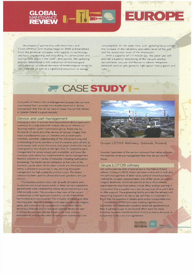
7/21/2019 Hydrocarbon Engineering Mayo 2014 Vol 19 05
http://slidepdf.com/reader/full/hydrocarbon-engineering-mayo-2014-vol-19-05 98/107
Developed in partnership with
Rom
inse rv and
ConocoPhillips, unit revamp began in 2008 and benefit
ed
fr om
the
American company wi
th
regards
to
techno logy
and basic engineering and consulting. Its
const
ru
ct
i
on
and
st rtup took place in the 2010 -
2013
pe riod. The updatin g
process dete rmined a 90% reduction of technolog ical
consumpt ion, an annual decrease
of
technological losses by
USS 3 mi
ll
ion, as well as a
sign
if
ic
ant reduction of energy
UROP
consumption.
At the
same time, such updati
ng
has provided
the increase of the re liability and safety level of the unit
and the pr
otec
tion level
of
the employees.
With a ca pa
ci
ty
of
1.1
7
milli
on
tpy. the coke r
un
it
wil
l
provide a superior processing of the vac
uum
residue
de rived from vacuum distillation to obtain integrated
products such
as
: gas. gasoline, light gasoil, heavy gasoit and
coke .
W SE SIU Y
Customers of Metso's
De
vice Management Business ervice hav
commented that It
provides
the v
aluable
expertise in device
management that they do
not
have in house.
The LOTOS
r
efine
l}'
in Gdansk. Poland
is agood
example.
Device and part management
Managing a valve
or
process field
measurement
devICe
spare
parts
Inventory for
a
large
Industrial complexlike
an
oil
refinery
S a
daunting task for
a
plant maintenance
group
.There ma
y
be
thousands
of valves
and
other devices of
various vintages
from
many
marufaJCturer; Lack
of a detailed and accurate parts
i
nventory.
IJ'ICertaln
lfifer>tanding of he
critical
parts required.
overstocking of some obsolete or out
of wanranty
parts.
all
add up
to increased costs and. In the worst
cases,
plant production
ma
y
be
interrupted by
lack
of
parts
at the
nght time
.To streamline
parts
management for
valves.
ensure parts availability
,
and lower the
i
nventory
costs
Metso has implemented its Device Management
Business
Solution
in
a
variety
of
industries including
hydrocarbon
processing. The results
c
an be substantial
,as
the
costsof the
inventory
can
be taken
off the
plant
's
books and the
experti
se
of
Metso
is
utilised to ensure dayto day and long term parts
management
for
high availability and
low
costs. This Metso
soiutlon has
been
used
for
all manufacturers'
products. not
just
Metso'
s,
The
busi
ness soiutlon s
tarts
with an
audit
of current parts
inventoriesand actual dev ice needs as there can
be
a substantial
g
ap
between
what
is needed
for critical
device
maintenance and
what actually
exists.
ThIS provides
a dear
view
of
the
current
installed base
so
the spare part inventory can be streamlined.
harmon
i
sed
and
costs
lowered
The
c
ritICality
of
Me\sO
and
other
manufacturers'
dev lCliS Is iSiiised
w
ith plant
p r r i d t
integrity
,
safety and en
v
ironmental comP.J\ance
In mind.
Next, Metso
develops a lifecyde
plari
to...,....,
an optim81 device nilx
and
inventoi}' for ""'iInd
into the
fUture
.Ow r time, it
allows
redundancJes
ancljhoIescenceOfspare
rts to be
Grupa LOrOS Refinery. Gdansk. Poland.
lo
w
ered.
Customers of
his
servke comment that
Metso
provides
the
experti
se
of
device management
that they do not
have In
house
.
Grupa
LOTOS re
finery
Just
suc
h a case has
been
implemented at the Gdansk
Poland
refinery
of Grupa LOTOS
.Metso has been contracted to look after
the parts management of 3600 valves
some
of
which have
been
work
ing
for 30 years.
Appro
xi
mately
20
of
the
valves
are MeISo
'
s,
Gregory 81edowski.Technical director at the LOTOS refinery.
appreciates the help
from
Metso's local office ,
and
has said that it
S Important that a supplier has avery strong local
office
and
is abie
to offer
support.
The
engineering
facility
proVides the refinery
with
""'Y
strong support in
its day
to day activities. It is
important
to
icnq
wthat
the
response
is
helpful. quick and
at a
reasonable
cost
MetsoandtOTOS have
been
working together since
September 2013: Bledowskl is positive about the agreement
but
feels it will
tab
a year to see the full effect since the
stock
Inventory has;been transferred from
LOTOS
to Metso,
however
. it
is
ex
pected to tie a win / win
agJ
eet
M I'lt.
GLOBAL

7/21/2019 Hydrocarbon Engineering Mayo 2014 Vol 19 05
http://slidepdf.com/reader/full/hydrocarbon-engineering-mayo-2014-vol-19-05 99/107
UROP
SE
SIU Y
a
n<;\gin,g cpntra
ct
or
Res
po
ns
ib
ili
ty for coordi
natrng
all
ma
in and subcontractors in
preparations and
planning
,
quality
, schedules and safety was
Bilfinger Ma intenance Nord's rem it for the autumn 2013
tu
rnaround
of
a refinery operated by Kuwa it Petroleum
Europoort in Rotterdam.Planni
ng
the proje
ct
took one year,
with the refinery turnaround lasting two months. At up to
350
0
operatives were
Simultaneouslydeployed at the si
te
.
The refinery was familiar terrain for the Silfinger experts. The
IndustrIal services prov ider
has
been a partner to Kuwait
Pe
t roleum Europoort
since
2006,
hav
i
ng
executed atotal of four
turnarounds at the site.
As
the managing contractor. the
company
was the customer s sole contact partner in the past.
assum
i
ng
full responsi
bil
Ity for the entire project.
In
the interests of
minim
ising production loss and costs, it is
generally more effic1ent to dose down the entire plant and to
perform
all
necessary
work
in a single
large
turnaround. Instead
of the partial turnarounds every two years in lIne with the
previOUS practice, the refinery Is now to undergo a full scale
turnaround in
roughly
five year intervals. The second trend
concerns the selection of the contractual partner. Potenti
al
service
prOV
iders for a turnaround are audited by the customer
we ll
in advance of the actual contract award these
days
.
References are also obtained for this purpose.
Whereas 350 operatives
work
on the entire site dUring
no
rmal
refinery operations. the workforce required for the
turnaround of all
fa
cilities number 2500 and at times. as
many
as
3500.
Silfinger alone
had
8 employees at the site
from
SIX
Silfinger companies in Germany, Austria.
th
e Netherlands and
Slo
v
akia
.
ln
addition to its
tasks
as
manag
ing contractor, SHfinger
handled scaffolding. insulation, coating, trace heating and piping
activities.
Ahead
of
the turnaround, up
to
8
employees were involved
in planning the mechanical w
ork and
piping rackIng
up
some
50 work hou rs. They were responsible fo r managing
monitoring and coordinating 18000 work packets, transporting.
storing and coordinating materials and transporting tools and the
necessary speCial vehICles to and from the site. As managing
contractor, Bilfinger was also in charge of site safety.This entailed
pl
anning
all precautions
in
consultation with the customer s top
level managemen
t.
As well as this,
it
was necessary
to
coordinate
the safety team stationed at the site.Consequently, no
reportable incidents arose, resulting
in
an lost time
Injury LTI)
ratio of zero.
The
turnaround was to be completed within tw
o
months at
the end
of
2
013
. Th is involved executing 80 ind ividual projects
and
coordinati
ng
15 other se
rvice
cornpanles pa rticipating in the
project,
The
turnaround
ma
terially owed its succe
ss to th
t
Ma
y
GLOBAL
REVEW
Bilfinger Maintenance Nord managed the
turnaround of the refinery operated by
Kuwait Petroleum Europoort in Rotterdam.
Bilfinger experts high technical
skills
and broad experience In
all
ma in turnaround areas. In addition. Si/finger benefited
from
its
intematlonal network via which it S able
to
access a l
arge
number of acti
vi
ties
and
qualified resources, allowing it to
comp
le
te complex projects with its own staff.
In addftion to the turnaround at Ku wait Petroleum
Europoort. Bllfinger completed other projects In
Germany
, the
Netherlands, Austria and the
Czech
Republic for Total Bitumen
Deutschland, BASF,PCK Raffiner ie Schwedt. Boreahs as well as
Cesk
a
Rafinerska
and Unipetrol in
20
13 The total value was
around € SO million. The largest ones were the turnarounds at
the
BASF
synthesis gas plant In Ludwlgshafen, at Borealis In Linz,
Austrla and Kuwait
Petroleum
Europoort in
Rotterdam in the
Netherlands.
7/21/2019 Hydrocarbon Engineering Mayo 2014 Vol 19 05
http://slidepdf.com/reader/full/hydrocarbon-engineering-mayo-2014-vol-19-05 100/107
combustion
le der
allidus Technologies, LLC
is
an
established world
leader in
process burner flare and thermal oxidizer technology.
We have earned that reputation by providing solutions that set new
standards in performance and
re
liability. Our approach to combustion
science continues to break new ground every day with innovative new
products and solutions for the worlds most difficult combustion
challenges. This commitment to technical excellence
is
driven by our
focus to provide a custom designed solution for every project based on each customer s specific
requirements. One example is our flare gas recovery system, designed to achieve zero flaring, reducing
process fuel costs while eliminating visible flame, odors and auxiliary flare utilities.
Having one
of
the largest installed bases of process burners, production flares and thermal oxidizers
in
refining and petrochemical facilities around the wo rld. Callidus should be yo
ur
choice for next generation
combustion equipment and solutions for new construction or retrofit operations with installation
capabilities anywhere in the world.
Callidus Technolog i
es,
LLC
A
Honeywell
ompany
7130 South Lewis, Suite 335,
Tutsa
, OK 74136, call 1-918-496-7599 or visit our website www.callidus.com
;)
2014 Honeywelllnternational Inc. All rights reserved.

7/21/2019 Hydrocarbon Engineering Mayo 2014 Vol 19 05
http://slidepdf.com/reader/full/hydrocarbon-engineering-mayo-2014-vol-19-05 101/107
UROP
R " , ~ ~ i i i
AVEVA announced
at t he
start of
this year,
that
Burgasnefteproekt , an engineering company in
the
field
of
petrochem
icals, had ach i
eved
significant
cost
savings using
AVEVA Laser odeller. Burgasnefteproekt recently acquired
the
AVEVA software
and used
it
to
capture
the as built
asset
and create a 3D
model of
an exis ting flaring
system
.
This
is
part
of
a revamp project
to
rebuild the system and
ensure up to date
. accurate project documentation. Using
3D
laser scanning technologies and processing the scan
data using AVEVA Laser odeller and AVEVA PDMS,
Burgasnefteproekt achieved approximately 80 savings in
design man hours.
The laser scan
data captured
from
the
faciltiy was
imported into AVEVA Laser Modeller, where the modelling
process is driven by the hig h resolut ion. photo realistic
BubbleVlew. On completion the new model was t rasferred to
AVEVA PDMS . The resu lt is an accurate 3D as built model
that
Burgasnefteproekt used fo r the revamp project, as well as
providing a valuable digital asset for future design and
maintenance activities.
Any
future plant modifications can be
easily compared with
the
as built 3D mode l as
the
LFM Server
technology can
be
used
to
reference the laser scan data
d irectly inside AVEVA PDMS .
The use
of
laser scanning technology on this project had
a Significant impact
on the
overall labour costs by making
the
process faster and more efficient. Us ing AVEVA technologies,
Burgasnefteproekt was able
to complete the documentation
in only
136
man hours. Using traditional ways of working,
the
same task would have taken between 700 and 9 man hours.
As
a result'.
the
company rapidly ga ined an accurate as built
3D
mode
l which can be used for r
edes
i
gn
.
Foster Wheeler
AG
announced
that
a subsidiary
of
its Global
Engineering and Construction Group was awarded a
contract
by OJSC Gazpromneft Moscow refinery
to
provide front end
engineering design
(FE
ED) and design
documentation in
accordance
with Russian Nor
ms
. for a major in
vestment
,
te rmed the combined oil refinery unit (CORU) project, at the
Moscow refinery. The value of the award was not disclosed
and will be included in Foster Wheeler's first quarter 2013
bookings.
The CORU project is part of the implementation of
Gazpromneft's OJSC Moscow refinery revamping and
upgrading program. under which
the
refinery will be
expanded up to 2020 to process an additional 6 million tpy
of
cru
de
oil and pr
od
u
ce
tra nsportation fuels
to
Euro V
standards.
The
CORU
facilities are planned
to
include crude
distillation and vacuum d
is
tillat ion units. a continuous
GLOBAL
MAM13'IANCE
REVEW
catalytic reforming unit with naphtha hydrotreatment and
hydrogen recovery by pressure swing adsorption, a diesel
hydrotreater including a dewaxing section. a gas planJ with a
LPG sweetening unit and common utilities.
LU Oil commissioned a diesel fuel hydrotr
eatment
unit at t he
Perm refinery towards the
end of
2013. The commissioned
technology
is
reequipp
ed
as part of
the
quadripartite
ag r
eement
signed in July
of
2011
by the
company.
the
Federa l
Antimonopoly Service. Rostekhnadzor and Rosstandart.
As
a
result
of
the
technical reequi
pment
. t
he
unit will increase
the
output
of
Eu ro 5 ult ra low sulfur diesel
ULSD)
fuel by
325 tpy. In add ition. the specific energy intensity of the
hydrotreatment process has
been
considerably reduced.
which enhances
the
production efficiency. The
expected 2014
ULSD fuel
output
at the Perm refinery is to exceed 4
mill
ion t.
Roseneft announced in October 2013 that subsidiary Saratov
refinery would undergo a modernisation and techno logical
upgrade as part of the planned overhaul
of
the facility tha t
lasted from 2nd October - Mid November 2013. This was one
of the largest investment initiatives as part of the program is
to ra ise the production efficiency
of
the
ELOU
-AVT-6 primary
refining unit
to
7 million tpy
to
ensure an Increase in
the
ext raction of vacuum gas oil. Other tasks included the
upgrade
of
processing units to
meet the
latest industrial
safety reqUirements.
The overhaul was predicted
to
be
the
largest in scale ever
since the company's foundation, with more than 1500 workers
employed at
the
apex
of the
program. With
the
job
done
,
the
facility enjoys a dramatic increase in oil refining volumes. not
to
mention t he improvement
of
processing equipment safety.
and
the
genera progress r
eac
h
ed
as part
of the
cont inuous
effort
to put
In action
the
wide ranging plans for
development
.
In
addit ion
to
the
above
work,
the
refinery made a reserve
stock
of
petroleum products and reached agreements
on
additional deliveries from
other
Rosneft refineries in
order to
ensure uninterruupted supplies
of
fuels to consumers during
the ove
rhaul period.
The Saratov refinery was founded in 1934. The enterprise
produces engine fuels meeting the most stringent Euro 5
ecological standards, as well as fuel oil. bitumen, vacuum gas
oil and technical sulfur.
~ r
In
the
summer
of
2013. NIS completed the investment
activities at the Pancevo oil refinery worth approximate ly 6
billion RSD. The process
of pe
rmanent improvement
of the
refming capacities has been continued after
the
successful
start up
of
t he MHC DHT complex for producing Euro 5

7/21/2019 Hydrocarbon Engineering Mayo 2014 Vol 19 05
http://slidepdf.com/reader/full/hydrocarbon-engineering-mayo-2014-vol-19-05 102/107
petroleum products. Since then the company has completed
the modernisation
of
the terminal at the river Danube and
continued to moderni
se
loading terminals. In addition, the
biggest refining complex for the production of gasoline and
gasoline components has been reconstructed. Numerous
Investments have been comple
ted to
reduce
the
producti
on
costs and achieve the level of energy efficiency.
in
cluding
thermal insulation In
24
tanks which implies the application
of
a special liquid ceramic insulation material.
In
the
two months following th is announcement.
all
requirements for
the
production
of
blodiesel with
the
appropriate com ponents content was expected
to
be met
and the investment was expected
to
allow NIS
to
export
petroleum products
to
countries within
the
.
Further work at
the
Pancevo refinery was carried out
in
October 2013 and included the replacement of worn out
relay protect ion in substation C and analyser installation at
the
platformmg unit in
the
refinery block S. These
investments were expected to increase operational
reliabil ity and energy efficiency and achieve financial savings
in the refini
ng
process.
Within
the
above process, three analysers were
ins
talled
at
each
of
the four furnaces
of
the platforming unit.
generating data which enables optimal combustion In the
furnaces. In addition. this investment, the value
of
which
exceeded 53 million RSD. ensured lower heavy fuel
consumption and a longer life cycle of the equipment. On an
annual basis. savings in heavy fuel consumption will range
rom
1630 -
2160 t.
In June
2013
new automatic compressor systems were
commissioned for
the
Novi Sad refinery with a
22 kW
capacity. Putting a modern compressor system
in
the Novi
Sad facility allowed it
to
cease using the outdated machine
and was expected
to
result
in
the
reduction
in
electricity
costs
by 85 as well as four times lower maintenance costs.
Replacement of the obsolete compressor system at the
refinery represented one
of
the stages
of
a comprehensive
program
of
increased energy efficiency in
the
operation
of all
organisational units of the company.
w ~ ~ ~ n
Honeywell has announced
that
it has been selected
by
Preem
AB
to modernise one of Europe s largest refineries.
Preemraf
Lysekil
, with Honeywell 's enhanced high
performance process manager (EH PM) industrial process
controller
s.
The project should
Sig
nificantly extend the ljfe
of
the existing control.system at the refinery, located
in
southern Swedep. Preem AB, is the country argest oil
producer and
will
use
the
enhanced high p e r f o r m a ~ c e
process manager to as much as trip{e the capacity of the
refinery s
eXIsting
controllers.
Preem has
an
annual refining capacity
of
more than
18 million
t,
accounting for 75
of
refining capacity in Sweden
and approximately one third
of
the entire Nordic region.
Preem is the largest supplier of ultra low sulfur diesel fuel in
Sweden, with a sulfur content
of
less than 5 ppm, Significantly
lower than
the Euro
4 requirement
of
50 ppm.
The upgrade will be completed during planned
maintenance at the refinery and will not require any
additional downtime.
It
is scheduled
to
be completed before
the
end
of the
year.
V
Flexitallic has secured a new three year contract with Total
lindsey oil refinery for the supply and servicing of standard
gaskets and exchangers at the refinery
in
North Lincolnshire.
The contract was secured through a competitive tender
process and continues a relationship in excess
of
20 years
between Flex itallic and the refinery at North Killingholme.
As part
of
the new agreement. Flexitallic, which has its
UK
headquarters in Cleckheaton, West Yorkshire. will contmue
to
deliver a range
of
its gasket technologies
to the
site.
Total Lindsey oil refinery
is
currently Britain s third largest.
with a processing capacIty of 200 bpd.
Teeside based construction and maintenance services
company, Hertel won a three year maintenance contract with
TOTAL
UK
in
the middle of 2013. The contract is related to
the Lindsey refinery in Immingham. Hertel has worked in
partnership with the refiner for nine years already. supporting
turnarounds and projects and under
the
new contract the
company will also be providing access services. thermal
insulation and painting.
1 ; 1 ~ ~ w . ~ r ~ j n I ; y r o p ~
In July 2013, one
of
the four industrial gas production leaders
worldwide and Burckhardt Compression Signed a field services
and valves maintenance framework supply agreement for
the
European terri tory. Under the agreement. Burckhardt
Compression will provide onsite field service and valve
service on
all
types
of
reciprocati
ng
compressors for more
than 40 industrial gas plants
in
Europe. The agreement
is
valid
for three years.
The agreement builds upon the excellent cooperation
between the two companies. The industrial gas production
company
is
a longstanding global partner
of
Burckhardt
Compressi.on in areas of new compressor systems and
compressor components and services. Further. the agreement
draws upon the strong service network
of
Burckhardt
Compression. its enhanced service capabilities and
comprehenSIve knowhow.
GLOB L
MAMENANCE

7/21/2019 Hydrocarbon Engineering Mayo 2014 Vol 19 05
http://slidepdf.com/reader/full/hydrocarbon-engineering-mayo-2014-vol-19-05 103/107
MI LE
E ST
MIDDLE
EAST
p pl: abi
Abu Dhabi Polymers Company (Borouge)
LLC
, a subsidiary
of
Adnot
awarded Kentech
Internatio
nal
Limited
Abu
Dhabi a
three
year
contract
in December last year.
The
contract
was for
the operation maintenance
and
repair services for
HVAC equipment at
Ruwa is plant .
Kentech
will
carry
out
operations
predict iv
e and
pre
ve
ntative
maintenance
. repairs and overhauls for
all
heat
ing, ventilation, refri
ge
r
ation
and a
ir co
nd itioning
systems
on th
e Borouge
pe
t rochemIcal facility
at
Ruwais.
approximately 250 km west o f Abu Dhabi city in the
UAE
.
Borouge
is
a jo i
nt venture between
the
Abu Dhabi
National Oil Company (ADNOC). one of the world's major
oil and gas
compani es
,
and
Aust ria
based
Boralis. a leading
provi
der
of
chemical and
i
nnovative plast
i S
solutions
.
The Production facility
at
Ruwais
is
ce
ntral
to
Bor
ou
ge's
op e
rat ions and by mid 2014 will have an annual
producto
in capacity of
4.5 mi
ll
ion t and will
be home to
the
world 's largest in
tegrated
polyolefins plant.
This
is
Kentech's
fi
rst
HVAC O&M
contract
in the
UAE
and
followed the
re
cen
t award
of
a similar
contract
in
Qatar
for She l
l.
These contracts
build
on
the
rapidly
developing operatio
ns
and
main
tenance
capability within
the
Kentech Group, and
provides
a solid
founda
t io n for
our
long te rm ambit ions in the Middle East.
Qahraill
Ba
hrain Petroleum Co. (Bapco)
expects
to
complete
an
upgrade
of
its only refinery in 2019,
that
will i
ncrease
processing
capacity
by
35%
.
Bapco plans
to start
work on upgrading
the
Sitra
refinery in
2015 in order to boost
its
capacity
to
360000
bpd
from
267
000
bpd
currently
.
Bapco
and
Saudi Arabian Oil Co. (Saud i Aramco)
are in
the
final
stages
of
approving work
on
enlarging a pipe line
that
carries Saudi light
crude to the
Sitra refinery by
120000 bbl to 350 000 bb l to feed the expans
io
n. The
two co
mpanies are
expected
to
sign
the
contract
for
the
pipeline work by
the end of th
is
ye
ar.
Iraq
SGS Oil, Gas Chemica ls Services (OGe) announced
in
September 2013 the
award
by Iraq
's
Ministry
of
Oil. Oil
Marketing Company (SOMO). fo r third
part
y metering and
inspect
ion services at
Al
Basrah oil terminal , Khor Alamava
oil terminal
and
Sing le pOint moorings.
SGS
OGC was
expected to commense operations towards the end of
September
. The opertations
are coordinated through
GLOBAL
w NTENANCE
REVEW
SGS
OGC's
UEA
regional
of
f
ic
e
in
Jebel
Ali
as a focal
point
and
is headed
by
the
International sales hubs in
Geneva
,
Houston
, London,
or
Singapore.
SGS OGC i
ntervent
ion under this
contract
will
include expertise
being
deployed
from
both upst
r
eam
and
downstream
working groups. The
scope of
work
i
ncludes
metering. sampling. calibration
and
trade
i
nspection
. In
addition
to
the
basic proviSion
of
profeSS ional serVICes,
SGS
OGC
is com
m
itted to
working
wit h SOMO
to
optimise
all
aspects of
the operations
fo r
stake
holde
rs.
u w a
Hydrop rocessing Associates
LLC
carried
out
work
for
KNPC.
The
company completed
re
trof
its , i
nternal
mod
ifications and repa irs o n
the
hydr
ocrackers
for five
beds. Two large vesse ls we re completely removed
with
one
bed
having
been lowered
and new Chevron
des
ign
trays ins
talled and
we l
ded in
safely
ahead of
schedule
with quality
to
the
highest standards.
At
the end
of 2013 , Technip was awa r
ded
by Kuwait Oil
Company
(KOC)
a cont r
act
worth
over US
400 million.
for
consultancy
services for
project management and
eng
inee
ring. This deals with the
construction
of ne w oil
and gas
in frast
r
ucture
faci lities. as well as
the
upg rad ing
of
ex is t ing facilit ies,
in
Kuwait. Technip will
prOV
i
de
services for
the
next five
ye
ars with an op tion
for
an
add
it ional
period of one
year.
.Om .ao.
Petrofac in a
50/50
jo int
ventu
re with Korean
based
Daelim Industr ia l Co Ltd was
awarded
a 36
month
engineering.
procurement
and
construction
(EPC)
contract by
Oman
Oil Refineries and Petroleum Industr ies
Company
(ORPIC)
. The
contract
value
is usS
2.1 billion.
Located
in the
Sohar Industria l Area, 230
km North
West
of Muscat, the
sco
pe of work encompasses engineering,
procurement
,
construction
,
startup
and commissioning
services
at
the
refinery. The
contract
includes
improvements
at the
eXisting facility as well as
the
addition
of new refining units.
The refinery was originally
constructed and
commissioned
10 2006
and
ORPIC IS
now investing in
improveme
nts
at
the
site
to
enhance the current
produ
ction
capacity
. When
complete
. it is
anticipated
that the revamped
facility will inc rease
current
output
by
more than
70%.

7/21/2019 Hydrocarbon Engineering Mayo 2014 Vol 19 05
http://slidepdf.com/reader/full/hydrocarbon-engineering-mayo-2014-vol-19-05 104/107
HEAT EXCHANGE
ENGINEERING
MIDDLE EAST 2 14
MANAMA
THE
KINGDOM
OF
BAHRAIN
19TH- 21ST OCTOBER 2014
CONFERENCE TRAINING EXHIBITION
Optimising Processes Improving Efficiency
Why should you attend?
Heat Exchange Engineering will provide
delegates with a
dedicated
event where they
can
connect
with exper
ts
and peers through
technical presentations discussions and
networking opportunities
to
gain knowledge and
n
understanding
of
best practice
in
industrial
heat exchange
The event s focused on advances n heat
exchange technology which deliver:
Improved
energy
efficiency
Reduced emissions
Increased throughput
etter
reliability
To
find
out more about
the
event please visit
heatexchangeengineering.com
HEE
EVENT
ORGANISERS:
I\
TE CHNOLOGY
TR NSFER
M N GEMENT
Who should attend?
The conference will bring together a
r nge
of
technical practitioners including:
Technical
management
Design
engineers
Energy
efficiency
managers
Plant engineers
Maintenance specialists
Equipment suppliers
Service
providers
Researchers
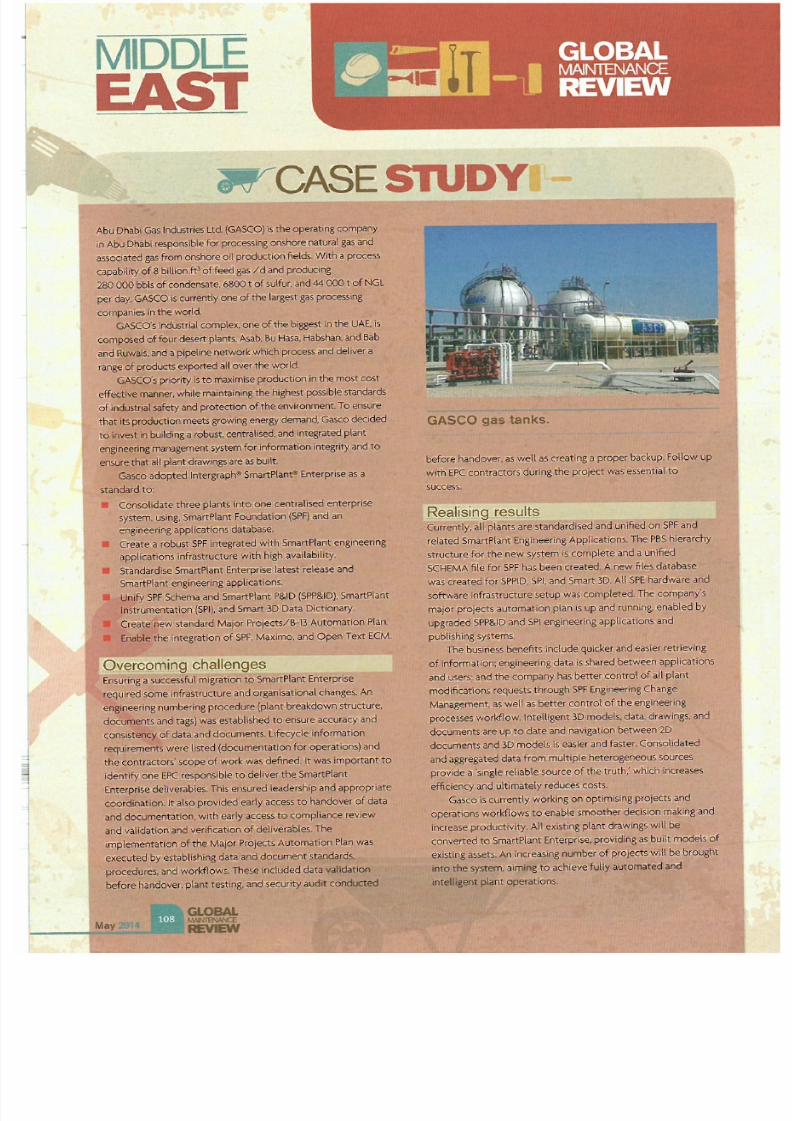
7/21/2019 Hydrocarbon Engineering Mayo 2014 Vol 19 05
http://slidepdf.com/reader/full/hydrocarbon-engineering-mayo-2014-vol-19-05 105/107
MIDDLE
E ST
W
C SE
SIU Y
Abo Dhabi Gas I
ndust
ries Ltd (GASCO) is the operating company
in
Abu Dhabl respon
sib
le for processing on5hore natural gas and
associated
gas
from onshore oil production
fields
. With a process
capability of 8
billion
ft of feed
gas
/ d and producing
28 000 bbls of condensate,6800 t of
sulfur,
and 44 000 t of NGL
pel
day
,GASCO is currently one of he largest
gas
processIng
companies in the world.
GASCO's
industrial
complex
,one of the biggest
in
the
UAE.
is
composed of
four
desert
plants,
Asab
,
u
Hasa
,
Habshan, and
Bab
and Ruwals, and a
plpehne
networkwhich process and deliver a
range of
p<oducts
exported
all
over the
world.
GASCO s priOrity
s
to
maximise
production
In
the most cost
effective mamer, while maintaining the highest
possib
le standards
of
industri
al safety
and protection of the environment
To
ensure
that Its production meets growing energy demand,
Gasco
decided
to
invest in build inga robust.
centralised.
and integrated plant
enginee
rin
g management system for informatfon Integrity and
to
ensu
re
that
all plant dr
awings
are as
built.
Gasco adopted Intergraph
l
m a r t l a n ~
Enter
prISe
as a
standard to:
Consolidate three plants into one centralised enterpr
ise
system.
using,
SmartPlant Foundation
(SPF)
and
an
engineering applicat ions database.
• Create a robust SPF Integrated with SmartPlant engineenng
applications infrastructu
re
with
high
availabi
li ty
.
• Standardise SmartPla nt Enterpr
ise
latest release and
SmartPlant engineering applications.
• U
nr
fy
SPF Schema and Sma
rt
Plant P
ID
(SP
P
ID)
, SmartPlan t
Instrumentation
(SPI),
and Smart
3D Data
Dictionary.
Create new standard Major Projects/B-13
Au
tomation Plan
• Enable
the integration of SPF,
Maximo
, and Open Text ECM
Overcoming c h a
l l ~ n g e s
Ensur
i
ng
a successful
migrat
ion
to
SmartPlant Enterpnse
requ
ired some infrastructure and organisational changes. An
engineering numbering procedure (plant breakdown structure.
documents
and tags) was
estabHshed to ensure accuracy
and
consistency
of
data and documents. lIfecyde Information
requirements were listed (documentation
for
operations)
and
the contractor
s'
scope of
work was defi
ned. It
was
Important
to
identify one EPC responsible
to
deliver the SmartPlant
Enterprise deliverables.This ensured leadership and appropriate
coordinat ion.
It
also provIded early access
to
handover of data
and documentation,
with
early access to compliance
review
and validatton and venfication of dellverables.The
implementation of the
Major
Projects Automation
Plan
was
executed by establishing data and document standards.
procedures, and
worl<flows
,These Included data validation
before handover, plant testIng, and security audit conducted
Ma
y
_
_
....-
GASCO gas t n s ,
before handover. as well as creating a proper ba.ckup. Follow up
with
EPC contractors during the project was essential
to
success.
Realising results
Currently, all plants are standardised and unified on SPF and
related SmartPlant Engineering Applications.
The
PBS hierarchy
structure for the new system is complete and a unified
SCHEMA
file
for SPF has been created, Anew files database
was
created for SP
PID.
SPI , and Smart 3D. All SPE hardware and
software infrastructure s
et
up
was
completed. The company s
major projects automation plan is up and running. enabled by
upgraded SP
P ID
and SPI engineeri
ng
applicatIOns and
publ ishing systems.
The business benefits include
quicker
and easier retrieving
of information; engineering data
1s
shared between applications
and users
; and the company
has
better control
of aU
plant
modifications requests through
SPF
Engineenng Change
Management.
as
wen
as
better control of the
eng
ineeri
ng
processes workflow. Intelligent
3D
models.data.
draWings.
and
documents are up to date and naVigation between 20
documents
and 3D
models Is easler and faster. Consolidated
and
aggregated data from multiple heterogeneous sources
provIde
a single reliable source of the truth:
which
increases
efficiency
and ultimately reduces costs.
Gasco
Is currently working on optimising projects and
operations workflows
to
enable smoother decision making and
increase productivity. All
existing
plant drawings will be
converted to 5martPlant Enterpr
ise.
providing
as
built
models of
existing
assets. An increasing number of projects wJII be brought
Into
the
system, aIming
to
achieve fully automate and
rnte1ligent plant operations.

7/21/2019 Hydrocarbon Engineering Mayo 2014 Vol 19 05
http://slidepdf.com/reader/full/hydrocarbon-engineering-mayo-2014-vol-19-05 106/107

7/21/2019 Hydrocarbon Engineering Mayo 2014 Vol 19 05
http://slidepdf.com/reader/full/hydrocarbon-engineering-mayo-2014-vol-19-05 107/107


