Page 1
Master’s Thesis
Hydroelastic Analysis of Floating Plate Structures
with Hinge Connections
Randi Gusto Jiwinangun
School of Mechanical, Aerospace and Systems Engineering
Division of Ocean Systems Engineering
KAIST
2012
Page 2
Hydroelastic Analysis of Floating Plate Structures
with Hinge Connections
Page 3
Hydroelastic Analysis of Floating Plate Structures
with Hinge Connections
Advisor : Professor Lee, Phill-Seung
by
Randi Gusto Jiwinangun
School of Mechanical, Aerospace and Systems Engineering
Division of Ocean Systems Engineering
KAIST
A thesis submitted to the faculty of KAIST in partial fulfillment of the re-
quirements for the degree of Master of Science in Engineering in the School of
Mechanical, Aerospace and Systems Engineering, Department of Ocean Sys-
tems Engineering. The study was conducted in accordance with Code of Re-
search Ethics1
12, 23, 2011
Approved by
Professor Lee, Phill-Seung
1Declaration of Ethical Conduct in Research: I, as a graduate student of KAIST, hereby declare that I have not
committed any acts that may damage the credibility of my research. These include, but are not limited to: falsi-
fication, thesis written by someone else, distortion of research findings or plagiarism. I affirm that my thesis
contains honest conclusions based on my own careful research under the guidance of my thesis advisor.
Page 4
Hydroelastic Analysis of Floating Plate Structures
with Hinge Connections
Randi Gusto Jiwinangun
The present dissertation has been approved by the dissertation committee
as a master’s thesis at KAIST
12, 23, 2011
Committee head
Committee member
Committee member
Lee, Phill-Seung
Park, Kwang-Chun
Kim, Byoung Wan
Page 5
i
MOSE
20104171
Jiwinangun, Randi Gusto. Hydroelastic Analysis of Floating Plate Structures with Hinge
Connections. School of Mechanical, Aerospace and Systems Engineering, Department of
Ocean Systems Engineering. 2012. 50 p. Advisor Prof. Lee, Phill-Seung. Text in English
ABSTRACT
The objectivity of this research is to investigate hydroelasticity of different length ratios of floating
plate structures with hinge connections under regular surface waves with assumptions newtonian isotropic, in-
viscid and irrotational flow. Comparisons with experiment results and previous numerical calculations have
been made for validation of method and mathematical formulation with the present structure and fluid model.
Multiple hinge connections at one and both sides of the structure are analyzed to investigate the hinge connec-
tions effectiveness based on the value of maximum moment occurred in the structure. Results shows that higher
stiffness parameter of floating plate structures have higher effectiveness when more hinge connections are ap-
plied.
Keywords: floating plate, hinge connections, MITC4 FEM, static condensation, BEM
Page 6
ii
Table of Contents
Abstract ································································································ i
Table of Contents ····················································································· ii
List of Tables and Figures ········································································· vi
Chapter 1. Introduction ············································································ 1
Chapter 2. General theory ········································································· 3
2.1 Overall description and assumptions ························································ 3
2.2 Floating plate structure model ······························································· 4
2.3 Fluid model ····················································································· 6
2.3.1 Boundary conditions········································································ 6
2.3.2 The free surface Green function ·························································· 7
2.3.3 Boundary integral equation ································································ 8
2.4 Coupled equations for frequency analysis ················································ 12
2.5 Dimensionless parameter ··································································· 13
2.6 Problem definition ··········································································· 13
Chapter 3. Numerical methods ································································· 16
3.1 MITC4 Plate element ······································································· 16
3.2 Static condensation ·········································································· 17
3.3 Boundary element ··········································································· 18
3.4 Discretize coupled equations ······························································· 19
3.5 Treatment of singularity ···································································· 21
3.2 Bending moments calculation ······························································ 22
Chapter 4. Results and Discussions ···························································· 24
4.1 Verification with an existing experiment ················································· 24
4.2 Validation with an existing numerical results ············································ 26
4.3 Floating plate structures with hinge connections at one side ··························· 27
4.4 Floating plate structures with hinge connections at both sides ························ 48
Chapter 5. Conclusion ············································································ 56
References ··························································································· 57
Page 7
iii
List of Tables and Figures
Figure 2.1: VLFS applications
Figure 2.2: Overall description of floating structures
Figure 2.3: Floating plate structure model
Figure 2.4: Fluid Domain
Figure 2.4: Fluid surface integration for the Green theorem
Figure 2.5: Fluid boundary description
Figure 2.6: Switching Structural System
Figure 2.7: Floating plate structures with hinge connection at one side of its structure
Figure 2.8: Floating plate structures with hinge connections at both sides of its structure
Figure 3.1: Plate element geometry
Figure 3.2: Boundary element geometry
Figure 3.3: Singular integral domains
Figure 3.4: Moments in plate element
Figure 4.1: Absolute displacement comparison of Yago’s experiment
Figure 4.2: Absolute bending moment comparison of Yago’s experiment
Figure 4.3: Absolute displacement comparison of S. Fu’s numerical calculation
Figure 4.4: Absolute bending moment at middle line for S. Fu’s numerical calculation
Figure 4.5: Absolute displacement for case of Lr=1, SS=10-4
, α=0.6, and θ=45deg
Figure 4.6: Maximum absolute displacement for case of Lr=1, SS=10-4
, and θ=45deg
Figure 4.7: Ratios of absolute maximum displacements for Lr=1
Figure 4.8: Absolute bending moment distribution at middle line for case of Lr=1, SS=10-4
, and
θ=45deg
Figure 4.9: Ratios of absolute maximum bending moments for Lr=1
Figure 4.10: Absolute displacement for case of Lr=2.5, SS=10-4
, α=0.6, and θ=45deg
Figure 4.11: Maximum absolute displacement for case of Lr=2.5, SS=10-4
, and θ=45deg
Figure 4.12: Ratios of absolute maximum displacements for Lr=2.5
Figure 4.13: Absolute bending moment distribution at middle line for case of Lr=2.5, SS=10-4
,
and θ=45deg
Figure 4.14: Ratios of absolute maximum bending moments of Lr=2.5
Figure 4.15: Absolute displacement for case of Lr=5, SS=10-4
, α=0.6, and θ=45deg
Page 8
iv
Figure 4.16: Maximum absolute displacement for case of Lr=5, SS=10-4
, and θ=45deg
Figure 4.17: Ratios of absolute maximum displacements for Lr=5
Figure 4.18: Absolute bending moment distribution at middle line for case of Lr=5, SS=10-4
,
and θ=45deg
Figure 4.19: Ratios of absolute maximum bending moments of Lr=5
Figure 4.20: Absolute displacement for case of Lr=7.5, SS=10-4
, α=0.6, and θ= 45deg
Figure 4.21: Maximum absolute displacement for case of Lr=7.5, SS=10-4
, and θ=45deg
Figure 4.22: Ratios of absolute maximum displacements for Lr=7.5
Figure 4.23: Absolute bending moment distribution at middle line for case of Lr=7.5, SS=10-4
,
and θ=45deg
Figure 4.24: Ratios of absolute maximum bending moments of Lr=7.5
Figure 4.25: Ratios of absolute maximum bending moments for the first problem
Figure 4.26: Absolute displacement for case of Lr=1, SS=10-4
, α=0.6, and θ= 45deg of multiple
hinges
Figure 4.27: Maximum absolute displacement for case of Lr=1, SS=10-4
, and θ=45deg of multi-
ple hinges
Figure 4.28: Ratios of absolute maximum displacements of multiple hinges
Figure 4.29: Absolute bending moment distribution at middle line of one multiple hinges for
case of SS=10-4
and θ=45deg
Figure 4.30: Absolute bending moment distribution at middle line of two multiple hinges for
case of SS=10-4
and θ=45deg
Figure 4.31: Absolute bending moment distribution at middle line of three multiple hinges for
case of SS=10-4
and θ=45deg
Figure 4.32: Ratios of absolute maximum bending moments of multiple hinges
Figure 4.33: Ratios of absolute maximum bending moments for the second problem
Figure 4.34: Overall ratios of absolute maximum bending moments.
Table 4.1: Test model description
Table 4.2: Numerical model description
Page 9
- 1 -
Chapter 1. Introduction
World population has reached seven billion in the year of 2011. United Nations has estimated a popula-
tion of 9.3 billion by 2050, and there is a prediction to be more than 10 billion people on Earth by 2100. The
more people live on the earth, means that available space will become less than before, especially on the land.
If there will be no more available space on the land, people will have no other option to use sea as a place to
live. One of the solutions to overcome this problem is by building very large floating structures (VLFS) which
was proposed by Japanese and American scientists. VLFS are structures that behave elastically under wave
pressure because of its large surface area and really small thickness, this phenomenon usually well known as
term hydroelasticity. In the recent years, VLFS are being developed as a floating oil storage, airport, bridge
and port.
Figure 2.1: VLFS applications. (Left to right: Shirashima oil storage terminal,
Kansai international airport, and SR 520 Washington bridge)
However, most of VLFS were designed as rigid structures on the sea surface. In the severe conditions,
VLFS may be in danger of failure under high wave loads and being unable to adapt to wave contours, causing
high stresses and bending moments to its structure. One solution applied to avoid this from happening is by
adding hinge connections into its structures. Hinge connections are expected to be working under harsh
weather and unable to work while VLFS in operation condition.
Various research and theories have been done to predict the hydroelastic response of floating structures.
Analytical prediction was developed using pressure distribution method based on hydroelastic response of
prototype structure using scale model on tank tests by Yago K. and Endo H [8]. Investigation of three dimen-
sional hydroelasticity of flexible floating interconnected structures modeled as rotational springs that incorpo-
rated with standard FEM procedures with incident wave parallel with structure’s length conducted by Fu, S.
[2]. To investigate optimum connection design of floating structure, Riyansyah, M. [7] used two floating
beams. In modeling hinge connection, many researchers modified value of stiffness matrix or added sub-
structures method into the structures. Hinge connection can be easily modeled into the stiffness matrix by us-
ing static condensation. Moreover, to do general investigation about hydroelastic response of floating struc-
Page 10
- 2 -
tures with hinge connection, VLFS should be analyzing for multi directional incoming waves.
Two main problems will be studied in this research; first problem is hinge connection at one side and both
sides of floating plate structures. The purpose of this study is to investigate the effectiveness of hinge connec-
tions for different geometries of floating structures based on multi directional incoming waves. The perfor-
mances for different number of hinge connections are based on comparison of maximum value of bending
moment between floating plate structures with and without hinge connections.
Page 11
- 3 -
Chapter 2. General Theory
This chapter describes mathematical model and formulation of hydroelastic analysis for various problems
on floating plate structures with hinge connections considered in this research. The physical assumptions,
governing equations and boundary conditions of the fluid and structure are presented. Final equations for
floating plate structure, is described in variational form of frequency domain. In generalizing design method,
dimensionless parameters are introduced for various problem analyses.
2.1 Overall description and assumptions
Figure 2.2: Overall description of floating structures
Very large floating structure is modeled as a floating plate structure. The floating plate structure with a to-
tal length L, breadth B, draft d and thickness t, floating on the water surface over a constant water depth h, in a
fixed Cartesian coordinate system which located at one of its corner and placed in the middle of its thickness.
A small amplitude of incident wave a is coming towards to the plate with wave length λ and angle θ, relative
to x-axis in the coordinate system and has positive value when it rotates in counter clockwise direction.
The structure is assumed to be homogeneous, isotropic and linear elastic with a small displacement and
strain. The fluid is assumed as homogenous, Newtonian isotropic, incompressible, inviscid, irrotational flow
fluid, and its surface tension is negligible. The incident wave is assumed to coming continuously with angular
frequency ω. Being the assumption of the system is linear, the motion of the structure and the fluid are time
harmonic with the same frequency.
Page 12
- 4 -
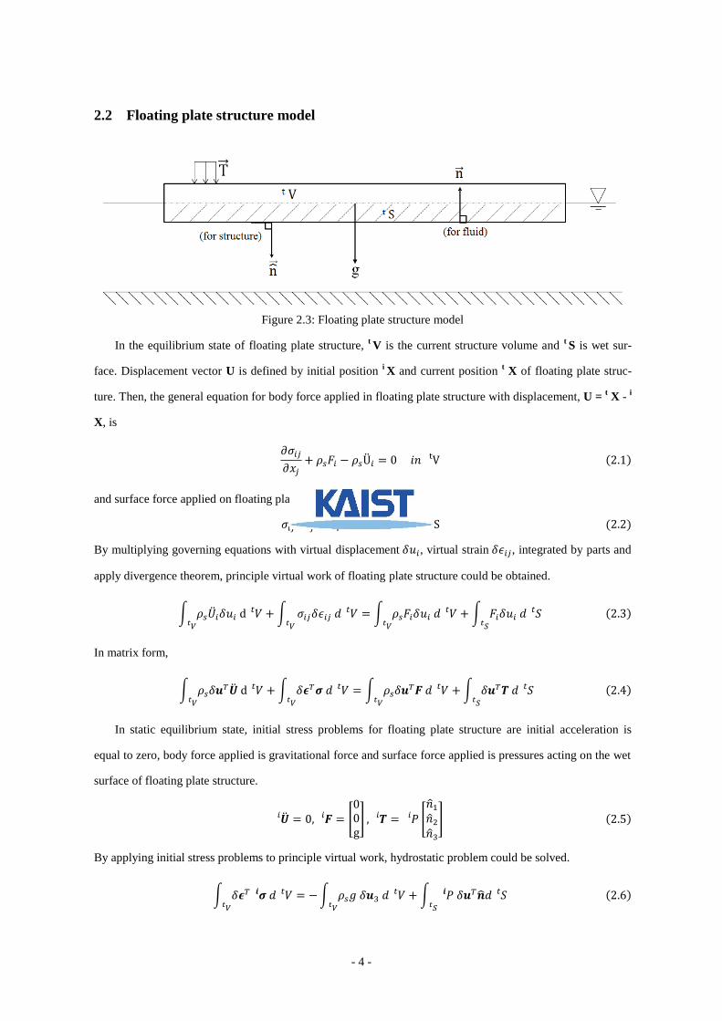
2.2 Floating plate structure model
Figure 2.3: Floating plate structure model
In the equilibrium state of floating plate structure, t V is the current structure volume and
t S is wet sur-
face. Displacement vector U is defined by initial position i X and current position
t X of floating plate struc-
ture. Then, the general equation for body force applied in floating plate structure with displacement, U = t X -
i
X, is
𝑖𝑗
𝑥𝑗 𝑖 𝑖 ( )
t
and surface force applied on floating plate structure is,
𝑖𝑗 𝑗 t ( )
By multiplying governing equations with virtual displacement 𝛿𝑢𝑖, virtual strain 𝛿 𝑖𝑗, integrated by parts and
apply divergence theorem, principle virtual work of floating plate structure could be obtained.
∫ 𝑖𝛿𝑢𝑖
∫ 𝑖𝑗𝛿 𝑖𝑗
∫ 𝑖𝛿𝑢𝑖
∫ 𝑖𝛿𝑢𝑖
( )
In matrix form,
∫ 𝛿
∫ 𝛿
∫ 𝛿
∫ 𝛿
( )
In static equilibrium state, initial stress problems for floating plate structure are initial acceleration is
equal to zero, body force applied is gravitational force and surface force applied is pressures acting on the wet
surface of floating plate structure.
𝑖 𝑖 [ g] 𝑖 𝑖 [
] ( )
By applying initial stress problems to principle virtual work, hydrostatic problem could be solved.
∫ 𝛿
∫ 𝛿
∫ 𝛿
( )
Page 13
- 5 -
For steady state problem, the solution will become,
∫ 𝛿
∫ 𝛿 ( )
∫ 𝛿
∫ ( )𝛿
( )
Then, the final solution for steady state problem can be obtained.
∫ 𝛿
∫ 𝛿
∫ 𝛿
( )
Using the assumptions of 𝑢(𝑥)𝑒𝑖𝜔 , (𝑥)𝑒𝑖𝜔 , (𝑥)𝑒𝑖𝜔 , [
]
Then, the final equation for floating plate structure is,
∫ 𝛿
∫ 𝛿
∫ (𝑥)
( )
Page 14
- 6 -
2.3 Fluid model
In modeling of the fluid, two conservations were used, conservation of mass and linear momentum. For
an ideal fluid (inviscid, incompressible, irrotational), motion of fluid particle could be described by velocity
potential by solving Laplace equation from the conservation of mass. Bernoulli’s equation can be derived
from conservation of linear momentum with additional assumptions of Newtonian and inviscid fluid.
𝛻𝜱 an 𝜱
𝑡
𝛻𝜱 𝛻𝜱
𝑷
𝑤 𝑢 ( )
2.3.1 Boundary conditions
Figure 2.4: Fluid Domain
Fluid domain around the floating structures is defined by surfaces, SB (body surface); SF (Free surface); SG
(Ground Surface); S∞ (Surface that shrouds fluid domain), as shown in figure 2.3. Normal velocity of structure
and fluid are same on the interface surface, then body boundary condition on the body surface is,
𝜙
𝑧 𝑢 ( )
The kinematic and dynamic boundary conditions at the free surface with a small amplitude (linearized) and
assumption of material derivative is equal zero are,
𝜙
𝑧 𝑢 𝜙 𝑢 an
𝜙
𝑧
𝜙 ( )
Since there is no flow normal into or out from sea bed, the kinematic boundary condition at ground surface is,
𝜙
𝑧 ( )
Scattered wave from structure and the wave caused by structure movements will be moving in radiation direc-
Page 15
- 7 -
tion to the infinity. This condition is called Sommerfeld radiation condition.
lim𝑟→∞
√𝑟 ( (𝜙 𝜙𝐼)
𝑟 𝑘(𝜙 𝜙𝐼)) 𝑤 𝑡ℎ 𝑟 √𝑥
𝑦 ( )
It was assumed that the incident potential is a plane wave given by,
𝜙𝐼𝑓𝑖𝑛
𝑎
cosh 𝑘(𝑧 ℎ)
𝑐 𝑠ℎ 𝑘ℎsin(𝑘(𝑥 cos 𝜃 𝑦 sin 𝜃))
𝑎
𝑐 𝑠ℎ 𝑘(𝑧 ℎ)
𝑐 𝑠ℎ 𝑘ℎcos(𝑘(𝑥 cos 𝜃 𝑦 sin 𝜃)) ( )
For finite depth.
𝜙𝐼𝑖𝑛𝑓
𝑎
𝑒𝑘𝑧 sin(𝑘(𝑥 cos 𝜃 𝑦 sin 𝜃))
𝑎
𝑒𝑘𝑧 cos(𝑘(𝑥 cos 𝜃 𝑦 sin 𝜃)) ( )
For infinite depth.
2.3.2 The free surface Green function
Free surface Green function is the basis for hydroelastic analysis in this research. The free surface Green
function is acting like a source potential located at 𝝃. Because The free surface Green function is nothing but
velocity potential, thus it has same body boundary conditions like velocity potential.
𝛻 𝐺 for ℎ ≤ 𝑧 ≤ except at 𝝃
𝐺
𝑧
g𝐺 at 𝑧
𝐺
𝑧 at 𝑧 ℎ
lim𝑅→∞
√𝑅 (
𝑅 𝑘)𝐺 for ℎ ≤ 𝑧 ≤ ( )
The source potential of strength for general case is equal to -4πr, so The free surface Green function for
infinite depth and finite depth can be obtained as follows,
𝐺𝑖𝑛𝑓 (
√𝑅 (𝑧 𝜉 ) ∫
𝑘 𝐾
𝑘 𝐾𝑒−𝑘|𝑧+𝜉3| 𝐽0(𝑘𝑅) 𝑘
∞
0
) ( 𝜋𝐾𝑒−𝑘|𝑧+𝜉3| 𝐽0(𝑘𝑅)) ( )
𝐺𝑓𝑖𝑛 (
√𝑅 (𝑧 𝜉 )
√𝑅 (𝑧 ℎ 𝜉 )
∫ (𝑘 𝐾)𝑒−𝑘 cosh 𝑘(𝜉 ℎ) 𝑐 𝑠ℎ 𝑘(𝑧 ℎ)
𝑘 sinh 𝑘ℎ 𝐾 cosh 𝑘ℎ 𝐽0(𝑘𝑅) 𝑘
∞
0
)
((𝐾 𝑘0)
𝑘0ℎ 𝐾 ℎ 𝐾
𝜋 cosh 𝑘0(𝜉 ℎ) 𝑐 𝑠ℎ 𝑘0(𝑧 ℎ) 𝐽0(𝑘𝑅)) ( )
Where 𝐾 𝜔2
g for infinite depth case and 𝐾 𝑘 tanh(𝑘ℎ) for infinite depth case. J0 is Bessel functions of
Page 16
- 8 -
the first kind of order 0, k0 is positive real roots of K, and P.V. is Cauchy principal value. Overall, The free
surface Green function can be summarized as follows,
𝐺(𝒙; 𝝃)
√(𝑥 𝜉 ) (𝑦 𝜉 )
(𝑧 𝜉 )
√(𝑥 𝜉 ) (𝑦 𝜉 )
(𝑧 𝜉 )
𝐾𝑒𝑘(𝑧+𝜉3)𝑙 *√(𝑥 𝜉 ) (𝑦 𝜉 )
(𝑧 𝜉 ) (𝑧 𝜉 )+ �� ( )
with the relation of distance r and r’,
𝑟 √(𝑥 𝜉 ) (𝑦 𝜉 )
(𝑧 𝜉 ) an 𝑟′ √(𝑥 𝜉 )
(𝑦 𝜉 ) (𝑧 𝜉 )
( )
Then, the general Green function in simple form is,
𝐺(𝒙; 𝝃)
𝑟
𝑟′ 𝐾𝑒𝑘(𝑧+𝜉3)𝑙 [𝑟′ (𝑧 𝜉 )] �� �� ( )
For plate problem, with properties of 𝑧 and 𝜉 then the general Green function will become,
𝐺(𝒙; 𝝃)
√(𝑥 𝜉 ) (𝑦 𝜉 )
√(𝑥 𝜉 ) (𝑦 𝜉 )
𝐾𝑙 *√(𝑥 𝜉 )
(𝑦 𝜉 ) + �� ( )
With assumption, 𝐾𝑙 [√(𝑥 𝜉 ) (𝑦 𝜉 )
] 𝐺 ≅ very small
Then, the general Green function for plate is,
𝐺(𝒙; 𝝃)
√(𝑥 𝜉 ) (𝑦 𝜉 )
𝑟𝑝𝑙𝑎 𝑒
𝑟 ( )
2.3.3 Boundary integral equation
The starting point was to do body boundary integral derived by Green’s theorem, which consists of two
potentials that satisfy Laplace equation.
Figure 2.4: Fluid surface integration for the Green theorem
Based on figure 2.4, the Green theorem for fluid can be derived as follows,
∫ 𝜙(𝝃) 𝐺(𝒙; 𝝃)
(𝝃) 𝐺(𝒙; 𝝃)
𝜙(𝝃)
(𝝃) + 𝜀
( 𝜀)
∫ 𝜙(𝝃) ∇ 𝐺(𝒙; 𝝃) 𝐺(𝒙; 𝝃) ∇ 𝜙(𝝃) ∇𝜙(𝝃) ∇𝐺(𝒙; 𝝃) ∇𝐺(𝒙; 𝝃) ∇𝜙(𝝃)
( )
Page 17
- 9 -
Then, by applying the Green function, which is mentioned in previous chapter, into the Green theorem equa-
tion, fluid surface integration could be obtained.
∫ 𝜙(𝝃) 𝐺(𝒙; 𝝃)
(𝝃) 𝐺(𝒙; 𝝃)
𝜙(𝝃)
(𝝃) + 𝜀
( 𝜀) ∫ 𝜙
(
𝑟)
𝑟
𝜙
+ 𝜀
( 𝜀) ( )
With, the Laplace equation, ∇ 𝜙 ∇ 𝐺 and ∇𝜙(𝝃) ∇𝐺(𝒙; 𝝃) ∇𝐺(𝒙; 𝝃) ∇𝜙(𝝃) ≅ very small ,
as assumptions, the Green theorem equation became,
∫ 𝜙
(
𝑟)
𝑟
𝜙
+ 𝜀
( 𝜀) ( )
Then, surface integration could be differ one to another by dividing the equation into two parts left hand side
with integration of surface S and right hand side with integration of surface 𝜀.
∫ 𝜙
(
𝑟)
𝑟
𝜙
∫ 𝜙
(
𝑟)
𝑟
𝜙
𝜀
𝜀 ( )
The analysis started with right hand side. On this side, the equation was divided into two parts. In order to
solve the equation, assumptions have been made, lim 휀 → (very small) and 𝜙= constant. The right hand
side of the Green theorem equation is,
{
∫ 𝜙
(
𝑟) 𝜀
𝜀⏟
∫
𝑟
𝜙
𝜀
𝜀⏟ }
( )
To solve the right hand side of the Green theorem equation, two assumptions have been made.
𝑛(
𝑟)
𝑟(
𝑟)
𝑟2 , then ∫
𝑟2 𝜀 𝜀
𝑟2 𝜀 ⏟
𝑒𝑟 𝑚𝑎𝑙𝑙 0
with 𝜀 𝜋𝑟
and
𝑛 , 𝜙 𝑐 𝑠𝑡𝑎 𝑡 ,
𝑛 (2.30)
By applying assumptions, the right hand side of the Green function will become,
, ∫ 𝜙
(
𝑟) 𝜀
𝜀
∫
𝑟
𝜙
𝜀
𝜀
- ≅ 𝜙(𝒙) ×
𝑟 × 𝜋𝑟 𝜋𝜙(𝒙) ( )
In general, the body boundary integral equation can be obtained as shown below,
∫ 𝜙
(
𝑟)
𝑟
𝜙
𝜋𝜙(𝒙) ( )
Page 18
- 10 -
Then, the final equation for floating plate problem can be obtained by replacing The free surface Green func-
tion into the general boundary integral equation.
∫ 𝜙(𝝃) 𝐺(𝒙; 𝝃)
(𝝃) 𝐺(𝒙; 𝝃)
𝜙(𝝃)
(𝝃)
𝜋𝜙(𝒙) ( )
Boundary conditions for floating plate problem, as shown in figure 2.4, are applied to the final boundary inte-
gral equation.
Figure 2.5: Fluid boundary description
Fluid domain of volume Vo surrounded by surface is the first thing to be considered.
𝜋𝜙(𝒙) ∫ (𝜙(𝝃) 𝐺(𝒙; 𝝃)
(𝝃) 𝐺(𝒙; 𝝃)
𝜙(𝝃)
(𝝃))
𝐵+ 𝐹+ ∞+ 𝐺
(𝝃)
∫ (𝜙(𝝃) 𝐺(𝒙; 𝝃)
(𝝃) 𝐺(𝒙; 𝝃)
𝜙(𝝃)
(𝝃))
𝐵
𝐵(𝝃) ∫ (𝜙(𝝃) 𝐺(𝒙; 𝝃)
(𝝃) 𝐺(𝒙; 𝝃)
𝜙(𝝃)
(𝝃))
∞
∞(𝝃)
∫ (𝜙(𝝃) 𝐺(𝒙; 𝝃)
(𝝃) 𝐺(𝒙; 𝝃)
𝜙(𝝃)
(𝝃))
𝐹
𝐹(𝝃) ∫ (𝜙(𝝃) 𝐺(𝒙; 𝝃)
(𝝃) 𝐺(𝒙; 𝝃)
𝜙(𝝃)
(𝝃))
𝐺
𝐺(𝝃)
(2.34)
Boundary conditions were applied for each surface surrounded the volume, at S∞ 𝜙 𝜙𝐼 , at SF
𝐺
𝑛
𝜔2
𝑔𝐺 ,
𝑛
𝜔2
𝑔𝜙 , and at SG
𝐺
𝑛 ,
𝑛 . Then, the final equation of volume Vo can be obtained
as follows,
𝜋𝜙(𝒙) ∫ (𝜙(𝝃) 𝐺(𝒙; 𝝃)
(𝝃) 𝐺(𝒙; 𝝃)
𝜙(𝝃)
(𝝃))
𝐵
𝐵(𝝃) ∫ (𝜙𝐼(𝝃) 𝐺(𝒙; 𝝃)
(𝝃) 𝐺(𝒙; 𝝃)
𝜙𝐼(𝝃)
(𝝃))
∞
∞(𝝃)
(2.35)
Same procedure was applied for incident wave. The boundary integral for incident wave is,
𝜋𝜙𝐼(𝒙) ∫ (𝜙𝐼(𝝃) 𝐺(𝒙; 𝝃)
(𝝃) 𝐺(𝒙; 𝝃)
𝜙𝐼(𝝃)
(𝝃))
𝐵+ 𝐹+ ∞+ 𝐺
(𝝃) ( )
Page 19
- 11 -
Then, the final equation for incoming wave can be obtained as follows,
𝜋𝜙𝐼(𝒙) ∫ (𝜙𝐼(𝝃) 𝐺(𝒙; 𝝃)
(𝝃) 𝐺(𝒙; 𝝃)
𝜙𝐼(𝝃)
(𝝃))
∞
∞(𝝃) ( )
Two equations of boundary integral equations for Vo and incident wave were added. The general equation of
boundary integral equation on for floating plate can be obtained,
𝜋𝜙(𝒙) 𝜋𝜙𝐼(𝒙) ∫ (𝜙(𝝃) 𝐺(𝒙; 𝝃)
(𝝃) 𝐺(𝒙; 𝝃)
𝜙(𝝃)
(𝝃))
𝐵
𝐵(𝝃) ( )
Boundary conditions for the Green functions were applied, at ground surface 𝐺
𝑧
𝜔2
𝑔𝐺 and at free
face
𝑧 𝑢 . Then, the equation transformed into,
𝜋𝜙(𝒙) 𝜋𝜙𝐼(𝒙) ∫ (𝜙(𝝃)
𝐺(𝒙; 𝝃) 𝐺(𝒙; 𝝃) 𝑢 )
𝐵
𝐵(𝝃)
∫ (𝜙(𝝃)
𝑢 ) 𝐺(𝒙; 𝝃)
𝐵
𝐵(𝝃) ( )
In order to solve previous equation, Bernoulli equation was used with the assumptions 𝚽 ϕ(𝒙)𝑒𝑖𝜔 and
𝑷 (𝒙)𝑒𝑖𝜔 , then Bernoulli equation will be as follows,
𝚽
𝑡
∇𝚽 ∇𝚽
𝑷
𝑤 𝑢
ϕ(𝒙)
∇ϕ(𝒙) ∇ϕ(𝒙)⏟ assume really small 0
(𝒙)
𝑤 𝑢 ϕ(𝒙)
(𝒙)
𝑤 𝑢 ( )
From Bernoulli equation, the relation between velocity potential and pressure can be obtained as follows,
ϕ(𝒙) 𝑖
𝜔(𝑃(𝒙)
𝜌𝑤 𝑢 ) an
𝜔
𝑔𝜌𝑤 (𝝃)
𝜔2
𝑔ϕ(𝝃) 𝑢 ( )
Velocity potential and pressure obtained from Bernoulli equation were applied to boundary integral equation.
𝜋
( (𝒙)
𝑤 𝑢 ) 𝜋𝜙𝐼(𝒙) ∫
𝑤 (𝝃)𝐺(𝒙; 𝝃)
𝐵
𝐵(𝝃) ( )
Then, the final equation for fluid will become,
𝑢
𝑤 (𝒙)
𝜋 𝑤∫ (𝝃)𝐺(𝒙; 𝝃) 𝐵
𝐵(𝝃)
𝜙𝐼(𝒙) ( )
Variational formulation for fluid equation is,
∫ 𝛿 (𝒙) 𝑢 𝐵
𝐵(𝒙)
𝑤∫ 𝛿 (𝒙) (𝒙) 𝐵
𝐵(𝒙)
𝜋 𝑤∫ 𝛿 (𝒙) (∫ (𝝃)𝐺(𝒙; 𝝃)
𝐵
𝐵(𝝃)) 𝐵
𝐵(𝒙)
∫ 𝛿 (𝒙) 𝜙𝐼(𝒙) 𝐵
𝐵(𝒙) ( )
Page 20
- 12 -
2.4 Coupled equations for frequency analysis
Variational form of floating plate structure and fluid equations are in the time domain. Floating plate
structure equation can be derived as follows,
∫ 𝛿
∫ 𝛿
∫ (𝑥)
( )
And for the fluid equation can be derived as follows,
∫ 𝛿 (𝒙) 𝑢 𝐵
𝐵 (𝒙)
𝑤∫ 𝛿 (𝒙) (𝒙) 𝐵
𝐵 (𝒙)
𝜋 𝑤∫ 𝛿 (𝒙) (∫ (𝝃)𝐺(𝒙; 𝝃)
𝐵
𝐵 (𝝃))
𝐵
𝐵 (𝒙)
∫ 𝛿 (𝒙) 𝜙𝐼(𝒙) 𝐵
𝐵 (𝒙) ( )
The assumption is small displacement, so the variation of changes for wet volume and surface of the
floating structure, fluid, and interface between them, are small in time t. Then, the volume and surface are in
static equilibrium, 𝐵 𝐵. Wet surface of the floating structure is the same like in the
body surface of the fluid, 𝐵 . Then, the analysis implemented in frequency domain. The final variation-
al equation of floating plate structure is,
∫ 𝛿
∫ 𝛿
∫ 𝛿 𝑷
𝐵
𝐵 ( )
And the variational equation of fluid is,
∫ 𝛿 (𝒙) 𝑢 𝐵
𝐵(𝒙)
𝑤∫ 𝛿 (𝒙) (𝒙) 𝐵
𝐵(𝒙)
∫ 𝛿 (𝒙) 𝜙𝐼(𝒙) 𝐵
𝐵(𝒙)
𝜋 𝑤∫ 𝛿 (𝒙) (∫ (𝝃)𝐺(𝒙; 𝝃)
𝐵
𝐵(𝝃)) 𝐵
𝐵(𝒙) ( )
Page 21
- 13 -
2.5 Dimensionless parameter
In generalizing design method of the problems that considered in this study, dimensionless design param-
eters of environmental surrounded the structure and structural properties of VLFS structure were introduced.
Parameters for structure contain specific information about VLFS stiffness and geometry and for fluid contain
specific information about incident wave that coming towards to the structure.
Overall, there are three dimensionless parameters that are being considered. Dimensionless parameter 𝐿𝑟
related to geometry is obtained from the relation between structure total length and width, later will be known
as length ratio of structure. Dimensionless parameter related to incident wave is obtained from the relation
of incident wave length and structure total length. The last dimensionless parameter is related to material
properties, structural flexibility, of structure which is related to bending stiffness of overall structure.
𝐿𝑟 𝐿
𝐿 an
𝐿 ( )
2.6 Problem definition
In this research, VLFS has two different kinds of connections installed into its structure. These two con-
nection will be working at different time depend on the environment surrounded floating structure. In service
condition, which weather rather calm, beam connection is working in the floating structure. Beam connection
will connects each different part of floating structure, enabling floating structure to do its function as a rigid
floating structure on the sea surface. If weather surrounded floating structure becomes severe, hurricane or
tsunami happened, beam connection will be failed and hinge connection will be working. The hinge connec-
tion is a free rotation connection which means that rotational stiffness is equal to zero. This change between
connections will be called as switching structural system. Switching structural system will allow floating
structure to survive in harsh weather.
Figure 2.6: Switching Structural System
Page 22
- 14 -
Two hydroelastic problems of floating structure with hinge connection are considered. In the first prob-
lem, the hydroelastic analysis of a floating plate structure consists of hinge connections at one side of the
structure is investigated. There are three cases being considered in this first problem:
Case 1 – Floating plate structure consists of one hinge connection (see Fig. 2.6.a)
Case 2 – Floating plate structure consists of two hinge connections (see Fig. 2.6.b)
Case 3 – Floating plate structure consists of three hinge connections (see Fig. 2.6.c)
(a) (b)
(c)
Figure 2.7: Floating plate structures with hinge connection at one side of its structure.
(a) First case; (b) second case; (c) third case.
The floating plate structures is subjected to an incident wave that coming from five different angles (0, 30,
45, 60, and 90 degrees) and seven different wave length ratios (0.2, 0.4, 0.6, 0.8, 1.0, 1.2, and 1.4). In the first
problem, four different length ratios (1, 2.5, 5, and 7.5) are considered. The effects of different length ratios
and structural stiffness parameter of the plates on the hydroelastic response of the floating plate are investigat-
ed.
In the second problem, the hydroelastic response of floating plate structures with hinge connections at its
both sides is investigated. There are three cases being considered in this second problem:
Case 1 – Floating plate structure consists of one hinge connection at both sides (see Figure 2.7.a)
Case 2 – Floating plate structure consists of two hinge connections at both sides (see Figure 2.7.b)
Case 3 – Floating plate structure consists of three hinge connections at both sides (see Figure 2.7.c)
Page 23
- 15 -
(a) (b)
(c)
Figure 2.8: Floating plate structures with hinge connections at both sides of its structure.
(a) First case; (b) second case; (c) third case.
Properties of environment surrounded floating plate structures are the same like in the previous problem.
It subjected to an incident wave that coming from five different angles (0, 30, 45, 60, and 90 degrees) and
seven different wave length ratios (0.2, 0.4, 0.6, 0.8, 1.0, 1.2, and 1.4). However, this problem only used one
value of length ratio, which equal to one, indicated it has same value of total length and width. All problems
will be subjected as infinite water depth case; even it has water depth h in its calculation.
Page 24
- 16 -
Chapter 3. Numerical methods
This chapter describes methods to solve structure and fluid equation. Finite element method (FEM) was
applied to structure domain and boundary element method (BEM) was applied to fluid domain. In modeling
hinge connection to structure domain, static condensation method was used. Method used in solving structure
and fluid equation is by coupled it together with relation to structure displacement and fluid pressure. Method
to solve singularities and bending moment calculation are presented.
3.1 MITC4 plate element
Figure 3.1: Plate element geometry
The plate formulation is a special case of the general shell element formulation and is based on the theory
of plates with transverse shear deformations. This theory, due to E. Reissner [6] and R.D. Mindlin [5], uses
the assumption that particles of the plate originally on a straight line that is normal to the un-deformed middle
surface remain on a straight line during deformation, but this line is not necessarily normal to the deformed
middle surface. With this assumption, the displacement components of point coordinate x, y, and z are,
[
] *
𝑧 (𝑥 𝑦)
𝑧 (𝑥 𝑦)
(𝑥 𝑦)
+
[ 𝑧∑ℎ𝑖𝜃
𝑖
𝑖
𝑧∑ℎ𝑖𝜃 𝑖
𝑖
∑ℎ𝑖𝑤𝑖
𝑖 ]
( )
Where is the transverse displacement and and are the rotations normal to un-deformed mid-
dle surface. In the pure displacement discretization, and , are transformed into and . The
bending strains are varying linearly through plate thickness. Assumption that stress in the direction of thick-
ness is zero, for isotropic material, the state of bending strain and stress are,
Page 25
- 17 -
⌈
⌉ 𝑧
[
𝑥
𝑦
𝑦
𝑥 ]
an ⌈
⌉ 𝑧
( 𝑣 )[
𝑣 𝑣
𝑣
]
[
𝑥
𝑦
𝑦
𝑥 ]
( )
MITC4 elements proposed by Bathe, K.J. [1] is used in the plate formulation. Contravariant base vector
was used in the formulation and its relation with covariant base vector explained through kronecker delta
function.
𝑖 𝑗 𝛿𝑖
𝑗{
an 𝑖 0
𝑟𝑖 ( )
The essence of MITC4 formulation lies in the separate interpolation of the transverse displacement (sec-
tion rotation) and of the transverse shear strains. As described earlier, the displacement and rotations are inter-
polated as usual, but for the transverse shear strains, the covariant components measured in the natural coordi-
nate system are interpolated. The transverse shear strains will be as follows
*𝛾 𝑧𝛾 𝑧+ *
𝑟𝑧( 𝑟 𝐞 )(
𝑧 𝐞𝑧) 𝑧( 𝐞 )(
𝑧 𝐞𝑧)
𝑟𝑧( 𝑟 𝐞 )(
𝑧 𝐞𝑧) 𝑧( 𝐞 )(
𝑧 𝐞𝑧)+ ( )
where,
𝑟𝑧
( 𝑠) 𝑟𝑧
𝐴
( 𝑠) 𝑟𝑧
𝐶
( 𝑠) [
ℎ
(𝑤 𝑤 )
ℎ
(𝑦 𝑦 )(𝜃
𝜃 )
ℎ
(𝑥 𝑥 )(𝜃
𝜃 )]
( 𝑠) [
ℎ
(𝑤 𝑤 )
ℎ
(𝑦 𝑦 )(𝜃
𝜃 )
ℎ
(𝑥 𝑥 )(𝜃
𝜃 )]
𝑧
( 𝑟) 𝑧
𝐷
( 𝑟) 𝑧
𝐵
( 𝑟) [
ℎ
(𝑤 𝑤 )
ℎ
(𝑦 𝑦 )(𝜃
𝜃 )
ℎ
(𝑥 𝑥 )(𝜃
𝜃 )]
( 𝑟) [
ℎ
(𝑤 𝑤 )
ℎ
(𝑦 𝑦 )(𝜃
𝜃 )
ℎ
(𝑥 𝑥 )(𝜃
𝜃 )]
𝑟 √g𝑟𝑟(sin 𝛽𝐞 cos 𝛽𝐞 ) , √g ( sin 𝐞 cos 𝐞 ) , 𝑧 √g𝑧𝑧𝐞𝑧 ( )
3.2 Static condensation
In modeling the hinge connections on the plate structure is modeled by using static condensation method.
Static condensation is employed to reduce number of elements degrees of freedom. For plate structure, rota-
tion in x or y direction will be condense out, depends on the location and axis of hinge connection. To perform
this method, it will be needed to assembling the structure matrices, structure stiffness K and force vectors R.
In order to establish equations used in static condensation, it was assumed that stiffness matrix and corre-
Page 26
- 18 -
sponding displacement and force vectors of the element under consideration are partitioned into the form,
[𝐊𝑎𝑎 𝐊𝑎𝑐𝐊𝑐𝑎 𝐊𝑐𝑐
] [𝐔𝑎𝐔𝑐] [
𝐑𝑎𝐑𝑐] ( )
Ua is the vectors displacement to be retained and Uc is the vectors displacement to be condensed out, re-
spectively. Using the second equation in the matrix, we can obtain,
𝐔𝑐 𝐊𝑐𝑐− (𝐑𝑐 𝐊𝑐𝑎𝐔𝑎) ( )
This relation is used to the first equation to substitute Uc, then the condensed equation can be obtain and Uc
will be disappear in the stiffness matrix. Later on, the information of 𝐊𝑐𝑐− and 𝐊𝑐𝑎 for each element through
condensation will be saved for re-condensation for bending moments calculation.
(𝐊𝑎𝑎 𝐊𝑎𝑐𝐊𝑐𝑐− 𝐊𝑐𝑎)𝐔𝑎 𝐑𝑎 𝐊𝑎𝑐𝐊𝑐𝑐
− 𝐑𝑐 ( )
Using the static condensation method explained before, the implementation in the plate structure will be
starting from the rearrangement of stiffness matrix according to the form of condensation matrix. Then, pro-
cess follows with condensation process. The process will be finished by re-assembly the stiffness matrix. For
the plate problem, for each element, static condensation happened twice, because two nodes at the side of el-
ement needed to define hinge connection.
3.3 Boundary elements
Figure 3.2: Boundary element geometry
Boundary elements method was used for the fluid by dividing the wet surface interface of fluid part with
structure into elements of four nodes element. The fluid wet surface is the same as middle surface of the plate
structure because plate thickness is so small, compared to its length and width. This method will be used in
the coupled equations. Then, interpolate pressure on the middle surface for four nodes boundary elements is
(𝑟 𝑠) ∑ℎ𝑘
𝑘
( )
Page 27
- 19 -
3.4 Discretize coupled equations
The final coupled equations were transformed into matrices form by applying MITC4 plate ele-
ments and boundary elements to structure and fluid equation. Each volume will be divided into sev-
eral elements. Structural volume divided into N elements and body surface into M elements. MITC4
plate finite element method applied to structure equation, it will become,
∫ 𝛿
∫ 𝛿
∫ 𝛿 𝑷
𝐵
𝐵
∫ 𝛿
∫ 𝛿𝜿 𝐂𝒃 𝜿 𝐵
𝐵 ∫ 𝛿𝛄 𝐂𝒔 𝛄 𝐵
𝐵 ∫ 𝛿 𝑷
𝐵
𝐵
𝑡∑∫ 𝛿 𝑒 𝑒 𝑒
𝑒𝑵
𝒆 𝟏
∑*∫ 𝛿
𝑒 𝑷𝑒 𝐵𝑒
𝐵𝑒+
𝑴
𝒆 𝟏
∑*∫ 𝛿𝜿 𝑒 𝐂𝒃 𝜿𝒆 𝐵𝑒
𝐵𝑒 ∫ 𝛿𝛄 𝑒 𝐂𝒔 𝛄𝑒
𝐵𝑒
𝐵𝑒+
𝑵
𝒆 𝟏
𝑡∑* 𝛿 𝑒 ∫ ∫ 𝐇𝑢
𝐇𝑢 et(𝐉) 𝑟𝟏
−𝟏
𝑠𝟏
−𝟏
𝒆 +
𝑵
𝒆 𝟏
∑* 𝛿 𝑒 ∫ ∫ 𝐡𝑢3
𝐡𝑝 et(𝐉) 𝑟𝟏
−𝟏
𝑠𝟏
−𝟏
��𝒆 +
𝑴
𝒆 𝟏
∑* 𝛿 𝑒 (∫ ∫ 𝐁𝜿
𝐂𝒃 𝐁𝜿 et(𝐉) 𝑟𝟏
−𝟏
𝑠𝟏
−𝟏
∫ ∫ 𝐁 𝐂𝒔 𝐁 et(𝐉) 𝑟
𝟏
−𝟏
𝑠𝟏
−𝟏
) 𝒆 +
𝑵
𝒆 𝟏
( )
Boundary element method applied to fluid equation, it will become
∫ 𝛿 (𝒙) 𝑢 𝐵
𝐵(𝒙)
𝑤∫ 𝛿 (𝒙) (𝒙) 𝐵
𝐵(𝒙)
∫ 𝛿 (𝒙) 𝜙𝐼(𝒙) 𝐵
𝐵(𝒙)
𝜋 𝑤∫ 𝛿 (𝒙) (∫ (𝝃)𝐺(𝒙; 𝝃)
𝐵
𝐵(𝝃)) 𝐵
𝐵(𝒙)
∑*∫ 𝛿 (𝒙) 𝑒 𝑢 𝑒 𝐵𝑒
𝐵𝑒(𝒙)+
𝑴
𝒆 𝟏
∑*
𝑤∫ 𝛿 (𝒙) 𝑒 (𝒙)𝑒 𝐵𝑒
𝐵𝑒(𝒙)+
𝑴
𝒆 𝟏
∑[
𝜋 𝑤∫ 𝛿 (𝒙) 𝑒 (∑*∫ (𝝃)�� 𝐺(𝒙; 𝝃)��
𝐵��
𝐵��(𝝃)+
𝑀
��
) 𝐵𝑒(𝒙)
𝐵𝑒
]
𝑀
𝑒
∑*
∫ 𝛿 (𝒙) 𝑒 𝜙𝐼(𝒙) 𝑒 𝐵𝑒
𝐵𝑒(𝒙)+
𝑴
𝒆 𝟏
∑* 𝛿��𝑒 ∫ ∫ 𝐡𝑝
𝐡𝑢3 et(𝐉) 𝑟𝟏
−𝟏
𝑠𝟏
−𝟏
𝑒 +
𝑴
𝒆 𝟏
∑* 𝛿��𝑒
𝑤∫ ∫ 𝐡𝒑
𝐡𝒑 et(𝐉) 𝑟𝟏
−𝟏
𝑠 ��𝑒
𝟏
−𝟏
+
𝑴
𝒆 𝟏
∑∑* 𝛿��𝑒
𝜋 𝑤∫ ∫ 𝐡𝑝
(∫ ∫ 𝐺(𝑟 𝑠; �� ��)𝐡𝒑 et(𝐉) ��𝟏
−𝟏
��𝟏
−𝟏
) et(𝐉) 𝑟𝟏
−𝟏
𝑠 ��𝑒
𝟏
−𝟏
+
𝑀
��
𝑀
𝑒
∑* 𝛿��𝑒
∫ ∫ 𝐡𝑝
𝜙𝐼 et(𝐉) 𝑟𝟏
−𝟏
𝑠 𝟏
−𝟏
+
𝑴
𝒆 𝟏
( )
Page 28
- 20 -
where
𝐡𝒑 [ℎ ℎ ℎ ℎ ]
𝐡 𝟑 [ℎ ℎ ℎ ℎ ]
𝑒 [ 𝑤 𝑒 𝑤 𝑒 𝑤 𝑒 𝑤 𝑒 𝜃
𝑒 𝜃
𝑒 𝜃
𝑒 𝜃
𝑒 𝜃
𝑒 𝜃
𝑒 𝜃
𝑒 𝜃
𝑒 ]
��𝒆 [ 𝑒 𝑒 𝑒 𝑒 ]
𝑒 (𝑟 𝑠) 𝐇𝑢 𝑒 𝑒 (𝑟 𝑠) 𝐡𝑢3 𝑒 𝑷𝒆 (𝑟 𝑠) 𝐡𝑝 ��𝒆
𝜿𝒆 𝐁𝜿 𝑒 𝛄𝑒 𝐁 𝑒
𝐇𝑢 [ 𝑧ℎ 𝑧ℎ 𝑧ℎ 𝑧ℎ 𝑧ℎ 𝑧ℎ 𝑧ℎ 𝑧ℎ
ℎ ℎ ℎ ℎ
]
𝐂𝒃 𝑡
( 𝑣 )[
𝑣 𝑣
𝑣
] 𝜿
[
𝑥
𝑦
𝑦
𝑥 ]
𝐂𝒔 𝑡𝑘
( 𝑣)*
+ ( )
In general, structure and fluid matrix coupled into one big matrix. As can be seen in the matrix below, the
first line of the general matrix is belongs to structural part and the second line is belongs to fluid part. By solv-
ing this general matrix, solution of displacement and pressure can be obtained.
[ 𝐒𝑀 𝐒𝐾 𝐒𝐼𝑛 𝐅𝐼𝑛 𝐅𝐾 𝐅𝑀
] * ��+ [
𝐅𝐼
] ( )
where
[𝑤 𝜃 𝜃
𝑤 𝜃 𝜃
𝑤𝑁 𝜃 𝑁 𝜃
𝑁]
�� [ 𝑀]
𝛿 𝐒𝑀 𝑡∑* 𝛿 𝑒
∫ ∫ 𝐇𝑢 𝐇𝑢 et(𝐉) 𝑟
𝟏
−𝟏
𝑠𝟏
−𝟏
𝒆 +
𝑵
𝒆 𝟏
𝛿 𝐒𝐾 ∑* 𝛿 𝑒 (∫ ∫ 𝐁𝜿
𝐂𝒃 𝐁𝜿 et(𝐉) 𝑟𝟏
−𝟏
𝑠𝟏
−𝟏
∫ ∫ 𝐁 𝐂𝒔 𝐁 et(𝐉) 𝑟
𝟏
−𝟏
𝑠𝟏
−𝟏
) 𝒆 +
𝑵
𝒆 𝟏
𝛿 𝐒𝐼𝑛 �� ∑* 𝛿 𝑒 ∫ ∫ 𝐡𝑢3
𝐡𝑝 et(𝐉) 𝑟𝟏
−𝟏
𝑠𝟏
−𝟏
��𝒆 +
𝑴
𝒆 𝟏
𝛿�� 𝐅𝐼𝑛 ∑* 𝛿��𝑒 ∫ ∫ 𝐡𝑝
𝐡𝑢3 et(𝐉) 𝑟𝟏
−𝟏
𝑠𝟏
−𝟏
𝑒 +
𝑴
𝒆 𝟏
𝛿�� 𝐅𝐾 �� ∑* 𝛿��𝑒
𝑤∫ ∫ 𝐡𝒑
𝐡𝒑 et(𝐉) 𝑟𝟏
−𝟏
𝑠 ��𝑒
𝟏
−𝟏
+
𝑴
𝒆 𝟏
Page 29
- 21 -
𝛿�� 𝐅𝑀�� ∑∑* 𝛿��𝑒
𝜋 𝑤∫ ∫ 𝐡𝑝
(∫ ∫ 𝐺(𝑟 𝑠; �� ��)𝐡𝒑 et(𝐉) ��𝟏
−𝟏
��𝟏
−𝟏
) et(𝐉) 𝑟𝟏
−𝟏
𝑠 ��𝑒
𝟏
−𝟏
+
𝑀
��
𝑀
𝑒
𝛿�� 𝐅𝐼 ∑* 𝛿��𝑒
∫ ∫ 𝐡𝑝
𝜙𝐼 et(𝐉) 𝑟𝟏
−𝟏
𝑠 𝟏
−𝟏
+
𝑴
𝒆 𝟏
( )
The symbol S is stand for structure and F is stand for fluid. Each structure and fluid part has matrix of
mass m, stiffness k, and interface Int. On the right side of structure part has value is equal to zero and for fluid
plate is equal to vectors of incident wave.
3.5 Treatment of singularity
The Green function in the fluid equation has singular value when distance between spatial point and
source point are really close or equal to zero. A method to solve singularity will be focused on the integration
of the Green function. Singular components for the green function should be separated from its regular com-
ponents. The integration of regular components of the Green function will be solved by Gauss-Legendre quad-
rature. As mentioned before in the previous chapter about free surface Green function, the Green function
could be generally in the form as follows,
𝐺(𝒙; 𝝃)
𝑟
𝑟′ 𝐾𝑒𝑘(𝑧+𝜉3)𝑙 [𝑟′ (𝑧 𝜉 )] �� �� ( )
Which S stands for singular component and the rest is regular component. For floating plate problem the
Green function will be in the form as follows,
𝐺(𝒙; 𝝃)
√(𝑥 𝜉 ) (𝑦 𝜉 )
√(𝑥 𝜉 ) (𝑦 𝜉 )
𝐾𝑙 *√(𝑥 𝜉 )
(𝑦 𝜉 ) + ��
𝐺(𝒙; 𝝃) �� ( )
Singular integral method to solve integration of the Green function was developed by Kim, Ki-Tae [3]. Ele-
ment was divided into four domains depends on the position of spatial point xp located on the element.
Figure 3.3: Singular integral domains
Page 30
- 22 -
Interpolation function will be transformed, so that it will has relation to the distance between spatial and
source point. The equation will be as follows
∑ℎ𝑘 𝑘
𝑘
𝐂𝑟 𝑟𝑠 𝐂𝑟𝑟 𝐂 𝑠 𝐂
𝐑 𝐂𝑟 (𝑟𝑠 𝑟𝑝𝑠𝑝) 𝐂𝑟(𝑟 𝑟𝑝) 𝐂
(𝑠 𝑠𝑝) ( )
Two singular integral equations, source and logarithmic type, were evaluated.
∫ ∫
‖𝐑‖ 𝑟
−
𝑠
−
an ∫ ∫ 𝑙 (‖𝐑‖ ) 𝑟
−
𝑠 ( )
−
Assumptions are made for each domain in the element. In the region A the assumptions will be as follows
𝑢 𝑟 𝑟𝑝; 𝑢𝑣 𝑠 𝑠𝑝 ( )
Then, singular integral equations of source and logarithmic type in the region A will be changed into
∫ ∫
‖𝐂𝑟 (𝑢𝑣 𝑣𝑟𝑝 𝑠𝑝) 𝐂𝑟 𝐂 𝑣‖
𝑣
− −𝑟 ⁄
− − −𝑟 ⁄
𝑢
−𝑟
−𝑟
∫ ∫ 𝑢 𝑙 (‖𝐂 𝒔( 𝒑 𝒔𝒑) 𝐂 𝐂𝒔 ‖
𝑢) 𝑟
− −𝑟 ⁄
− − −𝑟 ⁄
𝑠
−𝑟
−𝑟
( )
The singular integral became regular integral that can be solved by applying Gauss-Legendre quadrature. By
applying same procedure like in the region A, another three regions can be transformed into regular integrals.
For region A and C used assumptions
𝑢 𝑟 𝑟𝑝; 𝑢𝑣 𝑠 𝑠𝑝 ( )
and for region B and D used assumptions
𝑢𝑣 𝑟 𝑟𝑝; 𝑢 𝑠 𝑠𝑝 ( )
3.6 Bending moment calculation
Figure 3.4: Moments in plate element
The bending moments of Mxx, Myy and Mxy are stress resultants with dimension of moment per unit length
or force. Each of bending moments of the thin plate can be derive as below,
Page 31
- 23 -
M ∫ 𝑧 𝑧
⁄
−
⁄
∫ 𝑡
𝑟 𝑧
⁄
− ⁄
∫ 𝑡
𝑟 et(𝐉) 𝑟
−
∫ 𝑡
𝑟 𝑟
−
M ∫ 𝑧 𝑧
⁄
−
⁄
∫ 𝑡
𝑟 𝑧
⁄
− ⁄
∫ 𝑡
𝑟 𝑡 et(𝐉) 𝑟
−
M ∫ 𝑧 𝑧
⁄
−
⁄
∫ 𝑡
𝑟 𝑧
⁄
− ⁄
∫ 𝑡
𝑟 et(𝐉) 𝑟
−
( )
The integral relation between bending moments and stresses can be solved by applying numerical calcula-
tion. Displacement results of each element use to obtain bending moments of each element in the plate struc-
ture. The overall result of node on the plate elements are average value of bending moments at one node from
four different elements.
*
M M M
+ ∫ [
]
−
𝑡
𝑟 et(𝐉) 𝑟 ∫ 𝑧
( 𝑣 )[
𝑣 𝑣
𝑣
]
[
𝑥
𝑦
𝑦
𝑥 ]
−
𝑡
𝑟 et(𝐉) 𝑟
*
M M M
+ ∫ 𝑡
𝑟
[
( 𝑣 )
𝑣
( 𝑣 )
𝑣
( 𝑣 )
( 𝑣 )
( 𝑣)]
−
𝐁𝜿 𝑒 𝑟 ( )
Another way to calculate bending moments of plate structure is by analytical calculation which obtained
from solving the integral equation of previous bending moment equation. There will be no different in bend-
ing moment results between numerical and analytical calculation.
*
M M M
+ 𝑡
[
( 𝑣 )
𝑣
( 𝑣 )
𝑣
( 𝑣 )
( 𝑣 )
( 𝑣)]
𝐁𝜿 𝑒 ( )
Page 32
- 24 -
Chapter 4. Results and discussion
This chapter describes validation and verification of the formulation and method used in this study. Re-
sults of various problems subjected in this study are presented. Analysis and discussion of the results mainly
focused on maximum bending moment that occurs on the floating plate structure.
4.1 Verification with an existing experiment
In the early development of floating plate structure codes, verification of numerical formulation and
method applied are the first things needed, to ensure the obtained results are in accordance with the expected.
This verification can be implemented with comparison of results with another experiments or calculations. At
this stage, comparison was carried out to an experiment of hydroelastic response of scale modeled floating
structure on a tank test, performed by Yago K. and Endo H [8]. In the experiment, displacement and bending
moment was measured. The experiment object was a mat-like floating structure under regular waves load. The
test model is described in table 4.1,
Table 4.1: Test model description
Exp. subject Test Model Prototype
Scale ratio 1/30.77 1
Length (L), m 9.75 300
Breadth (B), m 1.9 60
Thickness (t), m 0.0545 2
Stiffness (EI), kgf.m2 1.788 x 10
3 4.87 x 10
10
Water depth 1.9m
λ/L & period 0.1 ~1.0 (0.8~2.5sec)
Wave height 1cm, 2cm, 6~7cm
Wave direction 0, 30, 60, 90 deg
Experiment results were compared only for cases of wave height equal to 1cm and incident wave direc-
tion equal to zero degree. The experiment results were presented in the value of absolute displacement in the
thickness direction divided by wave amplitude, or well known as term of response of motion (RAO) dis-
placement in z-direction, and absolute bending moments were divided by wave amplitude. Numerical and
experiment results of floating plate structures were compared each other. Comparison of absolute displace-
ment at the middle of the floating plate structure for different wave length ratios are shown in figure 4.1.
Page 33
- 25 -
Figure 4.1: Absolute displacement comparison of Yago’s experiment
Figure 4.2: Absolute bending moment comparison of Yago’s experiment
Another comparison was performed. Absolute bending moment is calculated and compared to the exper-
iment result, as explained in figure 4.2. In the absolute displacement comparisons, it showed that numerical
calculations met with the experiment result. Absolute bending moment calculations were in agreement with
experiment results. Overall, the calculated results showed satisfactory agreement with experiment results of
absolute displacements and bending moments of floating plate structure. It was appropriate to assume that
overall formulation and method applied in numerical calculation were suitable for hydroelastic analysis of
floating plate structures.
0
0.2
0.4
0.6
0.8
1
1.2
1.4
0 0.25 0.5 0.75 1
|u3|/a
x/L
Calculation
Yago Exp.
0
10
20
30
40
50
60
70
80
0 0.25 0.5 0.75 1
|Mxx|/a
(N.m
/cm
)
x/L
α=0.1
α=0.2
α=1.0
Calculation
Yago Exp.
Page 34
- 26 -
4.2 Validation with an existing numerical result
In the numerical calculation, static condensation method was used to model hinge connections in the
floating plate structures. It is necessary to validate the formulation and method that is implemented in the cal-
culation with another experiment or numerical results. At this stage, comparison with another numerical calcu-
lation performed by Fu, S. [2] was selected. The model for numerical calculation had same properties like in
the experiment as described before. Hinge connection was located in the middle of the floating plate structure
under five different wave length ratios. Absolute displacements in the thickness direction for both numerical
calculations were compared to each other as shown in figure 4.3 and absolute bending moment could be cal-
culated as shown in figure 4.4.
Figure 4.3: Absolute displacement comparison of S. Fu’s numerical calculation
Figure 4.4: Absolute bending moment at middle line for S. Fu’s numerical calculation
0
0.2
0.4
0.6
0.8
1
1.2
1.4
1.6
0 0.25 0.5 0.75 1
|u3|/a
x/L
α=0.2
α=0.4
α=0.8
α=0.6
Calculation
S. Fu Calc.
α=1.0
0
10
20
30
40
50
60
70
80
0 0.25 0.5 0.75 1
|Mx
x/a
| (N
.m/c
m)
x/L
α=0.2
α=0.6
α=0.8
α=1.0
α=0.4
Page 35
- 27 -
The absolute displacement comparison showed that the current calculations were in the satisfactory
agreement with another numerical calculation. Absolute bending moment calculations indicated that in the
middle of floating structure, which hinge connection was located, had value approaching nearly to zero value.
This stated that the formulation and method applied for modeling hinge connections was successfully done.
4.3 Floating plate structures with hinge connections at one side
As described before in the previous chapter, in this study, there were two mainly problems being consid-
ered. For all problems and cases, 60 square elements are used for floating plate model in length direction.
Properties for all cases are described in table 4.2.
Table 4.2: Numerical model description
units case 1 case 2 case 3 case 4
Length (L) m 9.75 9.75 9.75 9.75
Breadth (B) m 9.75 3.9 1.95 1.3
Thickness (t) m 0.0545
Draft (d) m 0.0166
Stiffness (EI) N.m2 2.698 x 10
2 ~ 2.698 x 10
6
Water Depth (h) m 1.9
Wave height (a) m 0.01
Wave frequency (ω) Hz 0.3 ~ 0.9
Wave length (λ) m 1.95 ~13.65
Wave direction degree 0, 30, 45, 60, and 90
Symbol case 1 case 2 case 3 case 4
Length Ratio Lr 1 2.5 5 7.5
λ/L α 0.2 ~ 1.4
Structure Stiffness Ss 1 x 10⁻⁶
~ 1 x 10⁻²
The first problem is hinge connection located at one side of floating plate structure. This means that hinge
connections have only one axis rotation, whether in x or y direction. Later on, in this chapter, each problem is
discussed according to length ratio floating plate structures; four in total, to ease analyze and relates one to
another. For the first case is length ratio equal to one which floating plate structures have same value in total
length and width. Generally, the results of floating plate structure are absolute displacements or bending mo-
ments. Figure 4.5 is shown one of absolute displacement results for various number of hinge connections.
Page 36
- 28 -
Figure 4.5: Absolute displacement for case of Lr=1, SS=10-4
, α=0.6, and θ=45deg
As can be seen from figure 4.5, hinge connections were affected absolute displacements of the floating
plate structure. It can be configured easily that incident wave is coming from 45 degrees angle, from the dif-
ferences of absolute displacement along the floating plate structures. Absolute displacement for every case of
floating plate structures could be calculated easily. However, the analysis will be uneasy to conduct because of
the number of results. Maximum absolute displacement is carried out for every case of floating plate structure
for different angles of incident wave. Figure 4.6 shows the maximum absolute displacement for the same case
of different wave length ratio of incident wave coming towards to the floating plate structures.
Figure 4.6: Maximum absolute displacement for case of Lr=1, SS=10-4
, and θ=45deg
0
0.2
0.4
0.6
0.8
1
1.2
1.4
1.6
1.8
2
0.2 0.4 0.6 0.8 1 1.2 1.4
|u3|/a
λ/L
no hinge connection
1 hinge connection
2 hinge connections
3 hinge connections
Page 37
- 29 -
The maximum absolute displacement had no big difference between floating plate structure with or with-
out hinge connections. The increase number of hinge connections did not affect the value of maximum abso-
lute displacements, especially for higher value of incident wave length ratio. However, the result of one case
of the problem could not described general result of the maximum absolute displacement.
Figure 4.7: Ratios of absolute maximum displacements for Lr=1.
0
0.5
1
1.5
2
2.5
3
3.5
4
4.5
5
0.2 0.4 0.6 0.8 1 1.2 1.4
|u3
max
| /
|u3
0 m
ax|
λ / L
1 hinge
1 hinge
1 hinge
1 hinge
1 hinge
Lr = 1
θ = 0 deg
1 hinge connection
SS = 10-6
SS = 10-5
SS = 10-4
SS = 10-3
SS = 10-2
0
0.5
1
1.5
2
2.5
3
3.5
4
4.5
5
0.2 0.4 0.6 0.8 1 1.2 1.4
|u3
max
| /
|u3
0 m
ax|
λ / L
2 hinges
2 hinges
2 hinges
2 hinges
2 hinges
Lr = 1
θ = 0 deg
2 hinge connections
SS = 10-6
SS = 10-5
SS = 10-4
SS = 10-3
SS = 10-2
0
0.5
1
1.5
2
2.5
3
3.5
4
4.5
5
0.2 0.4 0.6 0.8 1 1.2 1.4
|u3
max
| /
|u3
0 m
ax|
λ / L
3 hinges
3 hinges
3 hinges
3 hinges
3 hinges
Lr = 1
θ = 0 deg
3 hinge connections
SS = 10-6
SS = 10-5
SS = 10-4
SS = 10-3
SS = 10-2
0
0.25
0.5
0.75
1
1.25
1.5
1.75
2
2.25
2.5
0.2 0.4 0.6 0.8 1 1.2 1.4
|u3
max
| /
|u3
0 m
ax|
λ / L
1 hinge
1 hinge
1 hinge
1 hinge
1 hinge
Lr = 1
θ = 30 deg
1 hinge connection
SS = 10-6
SS = 10-5
SS = 10-4
SS = 10-3
SS = 10-2
0
0.25
0.5
0.75
1
1.25
1.5
1.75
2
2.25
2.5
0.2 0.4 0.6 0.8 1 1.2 1.4
|u3
max
| /
|u3
0 m
ax|
λ / L
2 hinges
2 hinges
2 hinges
2 hinges
2 hinges
Lr = 1
θ = 30 deg
2 hinge connections
SS = 10-6
SS = 10-5
SS = 10-4
SS = 10-3
SS = 10-2
0
0.25
0.5
0.75
1
1.25
1.5
1.75
2
2.25
2.5
0.2 0.4 0.6 0.8 1 1.2 1.4
|u3
max
| /
|u3
0 m
ax|
λ / L
3 hinges
3 hinges
3 hinges
3 hinges
3 hinges
Lr = 1
θ = 30 deg
3 hinge connections
SS = 10-6
SS = 10-5
SS = 10-4
SS = 10-3
SS = 10-2
0
0.25
0.5
0.75
1
1.25
1.5
1.75
2
2.25
2.5
0.2 0.4 0.6 0.8 1 1.2 1.4
|u3
max
| /
|u3
0 m
ax|
λ / L
1 hinge
1 hinge
1 hinge
1 hinge
1 hinge
Lr = 1
θ = 45 deg
1 hinge connection
SS = 10-6
SS = 10-5
SS = 10-4
SS = 10-3
SS = 10-2
0
0.25
0.5
0.75
1
1.25
1.5
1.75
2
2.25
2.5
0.2 0.4 0.6 0.8 1 1.2 1.4
|u3
max
| /
|u3
0 m
ax|
λ / L
2 hinges
2 hinges
2 hinges
2 hinges
2 hinges
Lr = 1
θ = 45 deg
2 hinge connections
SS = 10-6
SS = 10-5
SS = 10-4
SS = 10-3
SS = 10-2
0
0.25
0.5
0.75
1
1.25
1.5
1.75
2
2.25
2.5
0.2 0.4 0.6 0.8 1 1.2 1.4
|u3
max
| /
|u3
0 m
ax|
λ / L
3 hinges
3 hinges
3 hinges
3 hinges
3 hinges
Lr = 1
θ = 45 deg
3 hinge connections
SS = 10-6
SS = 10-5
SS = 10-4
SS = 10-3
SS = 10-2
0
0.25
0.5
0.75
1
1.25
1.5
1.75
2
2.25
2.5
0.2 0.4 0.6 0.8 1 1.2 1.4
|u3
max
| /
|u3
0 m
ax|
λ / L
1 hinge
1 hinge
1 hinge
1 hinge
1 hinge
Lr = 1
θ = 60 deg
1 hinge connection
SS = 10-6
SS = 10-5
SS = 10-4
SS = 10-3
SS = 10-2
0
0.25
0.5
0.75
1
1.25
1.5
1.75
2
2.25
2.5
0.2 0.4 0.6 0.8 1 1.2 1.4
|u3
max
| /
|u3
0 m
ax|
λ / L
2 hinges
2 hinges
2 hinges
2 hinges
2 hinges
Lr = 1
θ = 60 deg
2 hinge connections
SS = 10-6
SS = 10-5
SS = 10-4
SS = 10-3
SS = 10-2
0
0.25
0.5
0.75
1
1.25
1.5
1.75
2
2.25
2.5
0.2 0.4 0.6 0.8 1 1.2 1.4
|u3
max
| /
|u3
0 m
ax|
λ / L
3 hinges
3 hinges
3 hinges
3 hinges
3 hinges
Lr = 1
θ = 60 deg
3 hinge connections
SS = 10-6
SS = 10-5
SS = 10-4
SS = 10-3
SS = 10-2
Page 38
- 30 -
Figure 4.7: Ratios of absolute maximum displacements for Lr=1. (continue)
All results of absolute maximum displacements were carried out. Ratio between the absolute maximum
displacement of floating plate structures with and without hinge connections were calculated, as shown in
figure 4.7. Generally, the ratios became higher as stiffness parameter became higher and more hinge connec-
tions were applied to the floating plate structures. The ratios reached its peak for smaller value of wave length
ratio. This means that hinge connections allowed the floating plate structure to freely displace according to
wave length. Absolute bending moment calculations were carried out to analyze deeply about the floating
plate structures.
Figure 4.8: Absolute bending moment distribution at middle line for case of Lr=1, SS=10-4
, and θ=45deg
0
0.25
0.5
0.75
1
1.25
1.5
1.75
2
2.25
2.5
0.2 0.4 0.6 0.8 1 1.2 1.4
|u3
max
| /
|u3
0 m
ax|
λ / L
1 hinge
1 hinge
1 hinge
1 hinge
1 hinge
Lr = 1
θ = 90 deg
1 hinge connection
SS = 10-6
SS = 10-5
SS = 10-4
SS = 10-3
SS = 10-2
0
0.25
0.5
0.75
1
1.25
1.5
1.75
2
2.25
2.5
0.2 0.4 0.6 0.8 1 1.2 1.4
|u3
max
| /
|u3
0 m
ax|
λ / L
2 hinges
2 hinges
2 hinges
2 hinges
2 hinges
Lr = 1
θ = 90 deg
2 hinge connections
SS = 10-6
SS = 10-5
SS = 10-4
SS = 10-3
SS = 10-2
0
0.25
0.5
0.75
1
1.25
1.5
1.75
2
2.25
2.5
0.2 0.4 0.6 0.8 1 1.2 1.4
|u3
max
| /
|u3
0 m
ax|
λ / L
3 hinges
3 hinges
3 hinges
3 hinges
3 hinges
Lr = 1
θ = 90 deg
3 hinge connections
SS = 10-6
SS = 10-5
SS = 10-4
SS = 10-3
SS = 10-2
0
2
4
6
8
10
12
14
16
18
20
22
0 0.25 0.5 0.75 1
|Mxx|/a
(N.m
/cm
)
x/L
α=0.2
α=0.4
α=0.6
α=0.8
α=1.0
α=1.2
α=1.4
0
2
4
6
8
10
12
14
16
18
20
22
0 0.25 0.5 0.75 1
|Mxx|/a
(N.m
/cm
)
x/L
α=0.2
α=0.4
α=0.6 α=0.8
α=1.0
α=1.2
α=1.4
0
2
4
6
8
10
12
14
16
18
20
22
0 0.25 0.5 0.75 1
|Mx
x|/a
(N.m
/cm
)
x/L
α=0.2
α=0.4
α=0.6
α=0.8
α=1.0
α=1.2
α=1.4
0
2
4
6
8
10
12
14
16
18
20
22
0 0.25 0.5 0.75 1
|Mx
x|/a
(N.m
/cm
)
x/L
α=0.2
α=0.4
α=0.6
α=0.8
α=1.0
α=1.2
α=1.4
Page 39
- 31 -
Absolute bending moments were obtained from the absolute displacements of floating plate structures.
Figure 4.8 shows distribution of absolute bending moment along middle section of floating plate structure of
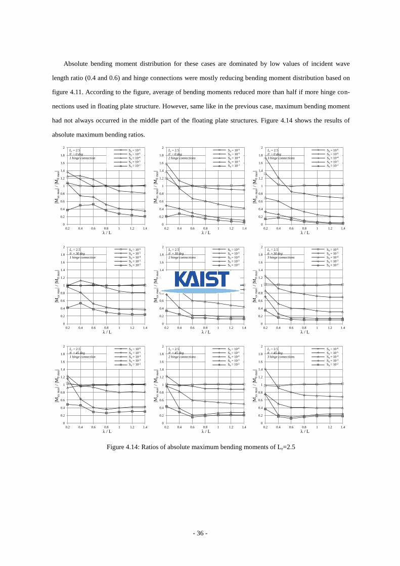
the specific previous cases. For these cases, absolute bending moment distributions were dominated by low
value of wave length ratios (0.4 and 0.6) and hinge connections were reducing the bending moment distribu-
tion, according to absolute bending moment distribution at the middle part of the structure with hinge connec-
tions. However, the maximum bending moment did not always occurred in the middle part of the structure. It
can be placed in any part of the structure, depends on the incident wave lengths and angles. In analyzing the
effectiveness of hinge connections for the structure, it is useful to develop ratio that relates one problem to
another problem, because the analysis is based on maximum bending moments, it is logic to build ratio that
correlated to maximum bending moments that occurred in the structure with and without hinge connections
that belonged to the same structural and wave properties.
Figure 4.9: Ratios of absolute maximum bending moments for Lr=1
0
0.2
0.4
0.6
0.8
1
1.2
1.4
1.6
1.8
2
0.2 0.4 0.6 0.8 1 1.2 1.4
|Mxx m
ax| /
|M0
max
|
λ / L
1 hinge
1 hinge
1 hinge
1 hinge
1 hinge
Lr = 1
θ = 0 deg
1 hinge connection
SS = 10-6
SS = 10-5
SS = 10-4
SS = 10-3
SS = 10-2
0
0.2
0.4
0.6
0.8
1
1.2
1.4
1.6
1.8
2
0.2 0.4 0.6 0.8 1 1.2 1.4
|Mxx m
ax| /
|M0
max
|
λ / L
2 hinges
2 hinges
2 hinges
2 hinges
2 hinges
Lr = 1
θ = 0 deg
2 hinge connections
SS = 10-6
SS = 10-5
SS = 10-4
SS = 10-3
SS = 10-2
0
0.2
0.4
0.6
0.8
1
1.2
1.4
1.6
1.8
2
0.2 0.4 0.6 0.8 1 1.2 1.4
|Mxx m
ax| /
|M0
max
|
λ / L
3 hinges
3 hinges
3 hinges
3 hinges
3 hinges
Lr = 1
θ = 0 deg
3 hinge connections
SS = 10-6
SS = 10-5
SS = 10-4
SS = 10-3
SS = 10-2
0
0.2
0.4
0.6
0.8
1
1.2
1.4
1.6
1.8
2
0.2 0.4 0.6 0.8 1 1.2 1.4
|Mxx m
ax| /
|M0
max
|
λ / L
1 hinge
1 hinge
1 hinge
1 hinge
1 hinge
Lr = 1
θ = 30 deg
1 hinge connection
SS = 10-6
SS = 10-5
SS = 10-4
SS = 10-3
SS = 10-2
0
0.2
0.4
0.6
0.8
1
1.2
1.4
1.6
1.8
2
0.2 0.4 0.6 0.8 1 1.2 1.4
|Mxx m
ax| /
|M0
max
|
λ / L
2 hinges
2 hinges
2 hinges
2 hinges
2 hinges
Lr = 1
θ = 30 deg
2 hinge connections
SS = 10-6
SS = 10-5
SS = 10-4
SS = 10-3
SS = 10-2
0
0.2
0.4
0.6
0.8
1
1.2
1.4
1.6
1.8
2
0.2 0.4 0.6 0.8 1 1.2 1.4
|Mxx m
ax| /
|M0
max
|
λ / L
3 hinges
3 hinges
3 hinges
3 hinges
3 hinges
Lr = 1
θ = 30 deg
3 hinge connections
SS = 10-6
SS = 10-5
SS = 10-4
SS = 10-3
SS = 10-2
0
0.2
0.4
0.6
0.8
1
1.2
1.4
1.6
1.8
2
0.2 0.4 0.6 0.8 1 1.2 1.4
|Mxx m
ax| /
|M0
max
|
λ / L
1 hinge
1 hinge
1 hinge
1 hinge
1 hinge
Lr = 1
θ = 45 deg
1 hinge connection
SS = 10-6
SS = 10-5
SS = 10-4
SS = 10-3
SS = 10-2
0
0.2
0.4
0.6
0.8
1
1.2
1.4
1.6
1.8
2
0.2 0.4 0.6 0.8 1 1.2 1.4
|Mxx m
ax| /
|M0
max
|
λ / L
2 hinges
2 hinges
2 hinges
2 hinges
2 hinges
Lr = 1
θ = 45 deg
2 hinge connections
SS = 10-6
SS = 10-5
SS = 10-4
SS = 10-3
SS = 10-2
0
0.2
0.4
0.6
0.8
1
1.2
1.4
1.6
1.8
2
0.2 0.4 0.6 0.8 1 1.2 1.4
|Mxx m
ax| /
|M0
max
|
λ / L
3 hinges
3 hinges
3 hinges
3 hinges
3 hinges
Lr = 1
θ = 45 deg
3 hinge connections
SS = 10-6
SS = 10-5
SS = 10-4
SS = 10-3
SS = 10-2
Page 40
- 32 -
Figure 4.9: Ratios of absolute maximum bending moments for Lr=1.(continue)
As can be seen from figure 4.9, lower value of stiffness parameter of floating plate structures, 10-6
~10-5
,
had no effect for any number of hinge connections for any different value of wave lengths and incident wave
angles. For the middle value of stiffness parameter, 10-4
, had no effect on one hinge connection. It had an
effect on two and three hinge connections in different incident wave lengths and angles. However, the
effectiveness of using more hinge connnections was not showing indication for improvement. For medium
high value of stiffness parameter, 10-3
, generally had constant efectiveness using hinge connections in
different incident wave lengths and angles. It had small effect on using higher number of hinge connections.
Higher value of stiffness paramter 10-2
, was really efective in using hinge connections. It had a better
effectiveness when using more hinge connections. However, its effectiveness using hinge connections for
lower value of incident wave length ratio droped significantly as wave angle more than 45 degrees. This
phenomenon might be caused by wave coming in width direction causing minimum value of bending moment
in x direction, so hinge connections which placed at plate length may be not effective.
The second case is for length ratio equal to 2.5. This means that the total width of the structure was
reduced about sixty percent from previous case. Structure properties changed from previous case, because of
the decrease value of total width that affected the value of Young’s modulus. However, the wave properties
such as incident wave lengths and angles were fixed like in the previous case. Figure 4.10 is shown one of
absolute displacement results for various number of hinge connections.
0
0.2
0.4
0.6
0.8
1
1.2
1.4
1.6
1.8
2
0.2 0.4 0.6 0.8 1 1.2 1.4
|Mxx m
ax| /
|M0
max
|
λ / L
1 hinge
1 hinge
1 hinge
1 hinge
1 hinge
Lr = 1
θ = 60 deg
1 hinge connection
SS = 10-6
SS = 10-5
SS = 10-4
SS = 10-3
SS = 10-2
0
0.2
0.4
0.6
0.8
1
1.2
1.4
1.6
1.8
2
0.2 0.4 0.6 0.8 1 1.2 1.4
|Mxx m
ax| /
|M0
max
|
λ / L
2 hinges
2 hinges
2 hinges
2 hinges
2 hinges
Lr = 1
θ = 60 deg
2 hinge connections
SS = 10-6
SS = 10-5
SS = 10-4
SS = 10-3
SS = 10-2
0
0.2
0.4
0.6
0.8
1
1.2
1.4
1.6
1.8
2
0.2 0.4 0.6 0.8 1 1.2 1.4
|Mxx m
ax| /
|M0
max
|
λ / L
3 hinges
3 hinges
3 hinges
3 hinges
3 hinges
Lr = 1
θ = 60 deg
3 hinge connections
SS = 10-6
SS = 10-5
SS = 10-4
SS = 10-3
SS = 10-2
0
0.2
0.4
0.6
0.8
1
1.2
1.4
1.6
1.8
2
0.2 0.4 0.6 0.8 1 1.2 1.4
|Mxx m
ax| /
|M0
max
|
λ / L
1 hinge
1 hinge
1 hinge
1 hinge
1 hinge
Lr = 1
θ = 90 deg
1 hinge connection
SS = 10-6
SS = 10-5
SS = 10-4
SS = 10-3
SS = 10-2
0
0.2
0.4
0.6
0.8
1
1.2
1.4
1.6
1.8
2
0.2 0.4 0.6 0.8 1 1.2 1.4
|Mxx m
ax| /
|M0
max
|
λ / L
2 hinges
2 hinges
2 hinges
2 hinges
2 hinges
Lr = 1
θ =90 deg
2 hinge connections
SS = 10-6
SS = 10-5
SS = 10-4
SS = 10-3
SS = 10-2
0
0.2
0.4
0.6
0.8
1
1.2
1.4
1.6
1.8
2
0.2 0.4 0.6 0.8 1 1.2 1.4
|Mxx m
ax| /
|M0
max
|
λ / L
3 hinges
3 hinges
3 hinges
3 hinges
3 hinges
Lr = 1
θ = 90 deg
3 hinge connections
SS = 10-6
SS = 10-5
SS = 10-4
SS = 10-3
SS = 10-2
Page 41
- 33 -
Figure 4.10: Absolute displacement for case of Lr=2.5, SS=10-4
, α=0.6, and θ=45deg
Absolute displacement in this case shows that the displacement in thickness direction is quite similar like
in the previous case, length ratio equal to one. This might be caused by the floating plate structure still has
moderate total width that allows deformation as elastic structure in the width direction. Absolute displacement
for every case of floating plate structures could be calculated easily. However, the analysis will be uneasy to
conduct because of the number of results. Maximum absolute displacement is carried out for every case of
floating plate structure for different angles of incident wave.
Figure 4.11: Maximum absolute displacement for case of Lr=2.5, SS=10-4
, and θ=45deg.
As can be seen, figure 4.11 shows the maximum absolute displacement for the previous case with
different incident wave lengths ratio. The figure showed that the maximum absolute displacement had no big
0
0.2
0.4
0.6
0.8
1
1.2
1.4
1.6
1.8
2
0.2 0.4 0.6 0.8 1 1.2 1.4
|u3|/a
λ/L
no hinge connection
1 hinge connection
2 hinge connections
3 hinge connections
Page 42
- 34 -
differences between the floating plate structures with or without hinge connections. The maximum absolute
displacements results showed a small difference value for smaller value of wave length ratio. The increase
number of hinge connections generally did not affect the value of maximum absolute displacements,
especially for higher values of incident wave length ratio. Ratio between the absolute maximum displacement
of floating plate structures with and without hinge connections were calculated, as shown in figure 4.12.
Figure 4.12: Ratios of absolute maximum displacements for Lr=2.5.
0
0.5
1
1.5
2
2.5
3
3.5
4
4.5
5
0.2 0.4 0.6 0.8 1 1.2 1.4
|u3
max
| /
|u3
0 m
ax|
λ / L
1 hinge
1 hinge
1 hinge
1 hinge
1 hinge
Lr = 2.5
θ = 0 deg
1 hinge connection
SS = 10-6
SS = 10-5
SS = 10-4
SS = 10-3
SS = 10-2
0
0.5
1
1.5
2
2.5
3
3.5
4
4.5
5
0.2 0.4 0.6 0.8 1 1.2 1.4
|u3
max
| /
|u3
0 m
ax|
λ / L
2 hinges
2 hinges
2 hinges
2 hinges
2 hinges
Lr = 2.5
θ = 0 deg
2 hinge connections
SS = 10-6
SS = 10-5
SS = 10-4
SS = 10-3
SS = 10-2
0
1
2
3
4
5
6
7
8
9
10
0.2 0.4 0.6 0.8 1 1.2 1.4
|u3
max
| /
|u3
0 m
ax|
λ / L
3 hinges
3 hinges
3 hinges
3 hinges
3 hinges
Lr = 2.5
θ = 0 deg
3 hinge connections
SS = 10-6
SS = 10-5
SS = 10-4
SS = 10-3
SS = 10-2
0
0.5
1
1.5
2
2.5
3
3.5
4
4.5
5
0.2 0.4 0.6 0.8 1 1.2 1.4
|u3
max
| /
|u3
0 m
ax|
λ / L
1 hinge
1 hinge
1 hinge
1 hinge
1 hinge
Lr = 2.5
θ = 30 deg
1 hinge connection
SS = 10-6
SS = 10-5
SS = 10-4
SS = 10-3
SS = 10-2
0
0.5
1
1.5
2
2.5
3
3.5
4
4.5
5
0.2 0.4 0.6 0.8 1 1.2 1.4
|u3
max
| /
|u3
0 m
ax|
λ / L
2 hinges
2 hinges
2 hinges
2 hinges
2 hinges
Lr = 2.5
θ = 30 deg
2 hinge connections
SS = 10-6
SS = 10-5
SS = 10-4
SS = 10-3
SS = 10-2
0
1
2
3
4
5
6
7
8
9
10
0.2 0.4 0.6 0.8 1 1.2 1.4
|u3
max
| /
|u3
0 m
ax|
λ / L
3 hinges
3 hinges
3 hinges
3 hinges
3 hinges
Lr = 2.5
θ = 30 deg
3 hinge connections
SS = 10-6
SS = 10-5
SS = 10-4
SS = 10-3
SS = 10-2
0
0.5
1
1.5
2
2.5
3
3.5
4
4.5
5
0.2 0.4 0.6 0.8 1 1.2 1.4
|u3
max
| /
|u3
0 m
ax|
λ / L
1 hinge
1 hinge
1 hinge
1 hinge
1 hinge
Lr = 2.5
θ = 45 deg
1 hinge connection
SS = 10-6
SS = 10-5
SS = 10-4
SS = 10-3
SS = 10-2
0
0.5
1
1.5
2
2.5
3
3.5
4
4.5
5
0.2 0.4 0.6 0.8 1 1.2 1.4
|u3
max
| /
|u3
0 m
ax|
λ / L
2 hinges
2 hinges
2 hinges
2 hinges
2 hinges
Lr = 2.5
θ = 45 deg
2 hinge connections
SS = 10-6
SS = 10-5
SS = 10-4
SS = 10-3
SS = 10-2
0
0.5
1
1.5
2
2.5
3
3.5
4
4.5
5
0.2 0.4 0.6 0.8 1 1.2 1.4
|u3
max
| /
|u3
0 m
ax|
λ / L
3 hinges
3 hinges
3 hinges
3 hinges
3 hinges
Lr = 2.5
θ = 45deg
3 hinge connections
SS = 10-6
SS = 10-5
SS = 10-4
SS = 10-3
SS = 10-2
0
0.25
0.5
0.75
1
1.25
1.5
1.75
2
2.25
2.5
0.2 0.4 0.6 0.8 1 1.2 1.4
|u3
max
| /
|u3
0 m
ax|
λ / L
1 hinge
1 hinge
1 hinge
1 hinge
1 hinge
Lr = 2.5
θ = 60 deg
1 hinge connection
SS = 10-6
SS = 10-5
SS = 10-4
SS = 10-3
SS = 10-2
0
0.25
0.5
0.75
1
1.25
1.5
1.75
2
2.25
2.5
0.2 0.4 0.6 0.8 1 1.2 1.4
|u3
max
| /
|u3
0 m
ax|
λ / L
2 hinges
2 hinges
2 hinges
2 hinges
2 hinges
Lr = 2.5
θ = 60 deg
2 hinge connections
SS = 10-6
SS = 10-5
SS = 10-4
SS = 10-3
SS = 10-2
0
0.5
1
1.5
2
2.5
3
3.5
4
4.5
5
0.2 0.4 0.6 0.8 1 1.2 1.4
|u3
max
| /
|u3
0 m
ax|
λ / L
3 hinges
3 hinges
3 hinges
3 hinges
3 hinges
Lr = 2.5
θ = 60 deg
3 hinge connections
SS = 10-6
SS = 10-5
SS = 10-4
SS = 10-3
SS = 10-2
Page 43
- 35 -
Figure 4.12: Ratios of absolute maximum displacements for Lr=2.5. (continue)
The ratios of absolute maximum displacements became higher as stiffness parameter became higher and
more hinge connections were applied to the floating plate structures. The ratios reached its peak for smaller
value of wave length ratio. This means that hinge connections allowed the floating plate structure to freely
displace according to wave length. Absolute bending moment calculations were carried out to analyze deeply
about the floating plate structures. Distribution of absolute bending moment at the middle line of the structure
can be calculated as shown in figure 4.13.
Figure 4.13: Absolute bending moment distribution at middle line
for case of Lr=2.5, SS=10-4
, and θ=45deg.
0
0.25
0.5
0.75
1
1.25
1.5
1.75
2
2.25
2.5
0.2 0.4 0.6 0.8 1 1.2 1.4
|u3
max
| /
|u3
0 m
ax|
λ / L
1 hinge
1 hinge
1 hinge
1 hinge
1 hinge
Lr = 2.5
θ = 90 deg
1 hinge connection
SS = 10-6
SS = 10-5
SS = 10-4
SS = 10-3
SS = 10-2
0
0.25
0.5
0.75
1
1.25
1.5
1.75
2
2.25
2.5
0.2 0.4 0.6 0.8 1 1.2 1.4
|u3
max
| /
|u3
0 m
ax|
λ / L
2 hinges
2 hinges
2 hinges
2 hinges
2 hinges
Lr = 2.5
θ = 90 deg
2 hinge connections
SS = 10-6
SS = 10-5
SS = 10-4
SS = 10-3
SS = 10-2
0
0.25
0.5
0.75
1
1.25
1.5
1.75
2
2.25
2.5
0.2 0.4 0.6 0.8 1 1.2 1.4
|u3
max
| /
|u3
0 m
ax|
λ / L
3 hinges
3 hinges
3 hinges
3 hinges
3 hinges
Lr = 2.5
θ = 90 deg
3 hinge connections
SS = 10-6
SS = 10-5
SS = 10-4
SS = 10-3
SS = 10-2
0
10
20
30
40
50
60
0 0.25 0.5 0.75 1
|Mxx|/a
(N.m
/cm
)
x/L
α=0.2
α=0.4
α=0.6
α=0.8
α=1.0
α=1.2
α=1.4
0
10
20
30
40
50
60
0 0.25 0.5 0.75 1
|Mxx|/a
(N.m
/cm
)
x/L
α=0.2
α=0.4
α=0.6
α=0.8
α=1.0
α=1.2
α=1.4
0
4
8
12
16
20
24
0 0.25 0.5 0.75 1
|Mxx|/a
(N.m
/cm
)
x/L
α=0.2
α=0.4
α=0.6
α=0.8
α=1.0
α=1.2
α=1.4
0
2
4
6
8
10
12
0 0.25 0.5 0.75 1
|Mx
x|/a
(N.m
/cm
)
x/L
α=0.2
α=0.4
α=0.6
α=0.8
α=1.0
α=1.2
α=1.4
Page 44
- 36 -
Absolute bending moment distribution for these cases are dominated by low values of incident wave
length ratio (0.4 and 0.6) and hinge connections were mostly reducing bending moment distribution based on
figure 4.11. According to the figure, average of bending moments reduced more than half if more hinge con-
nections used in floating plate structure. However, same like in the previous case, maximum bending moment
had not always occurred in the middle part of the floating plate structures. Figure 4.14 shows the results of
absolute maximum bending ratios.
Figure 4.14: Ratios of absolute maximum bending moments of Lr=2.5
0
0.2
0.4
0.6
0.8
1
1.2
1.4
1.6
1.8
2
0.2 0.4 0.6 0.8 1 1.2 1.4
|Mxx m
ax| /
|M0
max
|
λ / L
1 hinge
1 hinge
1 hinge
1 hinge
1 hinge
Lr = 2.5
θ = 0 deg
1 hinge connection
SS = 10-6
SS = 10-5
SS = 10-4
SS = 10-3
SS = 10-2
0
0.2
0.4
0.6
0.8
1
1.2
1.4
1.6
1.8
2
0.2 0.4 0.6 0.8 1 1.2 1.4
|Mxx m
ax| /
|M0
max
|
λ / L
2 hinges
2 hinges
2 hinges
2 hinges
2 hinges
Lr = 2.5
θ = 0 deg
2 hinge connections
SS = 10-6
SS = 10-5
SS = 10-4
SS = 10-3
SS = 10-2
0
0.2
0.4
0.6
0.8
1
1.2
1.4
1.6
1.8
2
0.2 0.4 0.6 0.8 1 1.2 1.4
|Mxx m
ax| /
|M0
max
|
λ / L
3 hinges
3 hinges
3 hinges
3 hinges
3 hinges
Lr = 2.5
θ = 0 deg
3 hinge connections
SS = 10-6
SS = 10-5
SS = 10-4
SS = 10-3
SS = 10-2
0
0.2
0.4
0.6
0.8
1
1.2
1.4
1.6
1.8
2
0.2 0.4 0.6 0.8 1 1.2 1.4
|Mxx m
ax| /
|M0
max
|
λ / L
1 hinge
1 hinge
1 hinge
1 hinge
1 hinge
Lr = 2.5
θ = 30 deg
1 hinge connection
SS = 10-6
SS = 10-5
SS = 10-4
SS = 10-3
SS = 10-2
0
0.2
0.4
0.6
0.8
1
1.2
1.4
1.6
1.8
2
0.2 0.4 0.6 0.8 1 1.2 1.4
|Mxx m
ax| /
|M0
max
|
λ / L
2 hinges
2 hinges
2 hinges
2 hinges
2 hinges
Lr = 2.5
θ = 30 deg
2 hinge connections
SS = 10-6
SS = 10-5
SS = 10-4
SS = 10-3
SS = 10-2
0
0.2
0.4
0.6
0.8
1
1.2
1.4
1.6
1.8
2
0.2 0.4 0.6 0.8 1 1.2 1.4
|Mxx m
ax| /
|M0
max
|
λ / L
3 hinges
3 hinges
3 hinges
3 hinges
3 hinges
Lr = 2.5
θ = 30 deg
3 hinge connections
SS = 10-6
SS = 10-5
SS = 10-4
SS = 10-3
SS = 10-2
0
0.2
0.4
0.6
0.8
1
1.2
1.4
1.6
1.8
2
0.2 0.4 0.6 0.8 1 1.2 1.4
|Mxx m
ax| /
|M0
max
|
λ / L
1 hinge
1 hinge
1 hinge
1 hinge
1 hinge
Lr = 2.5
θ = 45 deg
1 hinge connection
SS = 10-6
SS = 10-5
SS = 10-4
SS = 10-3
SS = 10-2
0
0.2
0.4
0.6
0.8
1
1.2
1.4
1.6
1.8
2
0.2 0.4 0.6 0.8 1 1.2 1.4
|Mxx m
ax| /
|M0
max
|
λ / L
2 hinges
2 hinges
2 hinges
2 hinges
2 hinges
Lr = 2.5
θ = 45 deg
2 hinge connections
SS = 10-6
SS = 10-5
SS = 10-4
SS = 10-3
SS = 10-2
0
0.2
0.4
0.6
0.8
1
1.2
1.4
1.6
1.8
2
0.2 0.4 0.6 0.8 1 1.2 1.4
|Mxx m
ax| /
|M0
max
|
λ / L
3 hinges
3 hinges
3 hinges
3 hinges
3 hinges
Lr = 2.5
θ = 45 deg
3 hinge connections
SS = 10-6
SS = 10-5
SS = 10-4
SS = 10-3
SS = 10-2
Page 45
- 37 -
Figure 4.14: Ratios of absolute maximum bending moments of Lr=2.5.(continue)
Exactly the same like results in previous case, lowest value of stiffness parameter of floating plate struc-
tures, 10-6
, had no effect for hinge connection for different value of incident wave ratios and angles. For medi-
um lower value of stiffness parameter, 10-5
, was showing small improvement in using more hinge connec-
tions. On the other hand, for the middle value of stiffness parameter, 10-4
, had slightly effectiveness for one
hinge connection. It had an effect in using two and three hinge connections in different incident wave lengths
and angles. For medium high value of stiffness parameter, 10-3
, generally had a constant effectiveness using
hinge connections in different incident wave lengths and angles, except for higher incident wave length ratios
of incident wave angle equal to 90 degree. The highest value of stiffness parameter, 10-2
, became more effec-
tive if using more hinge connections. Compare to previous problem, its effectiveness using hinge connections
improved for wave angle equal to 60 degree. The effectiveness of using hinge connections were still dropping
significantly as wave angle is equal to 90 degrees, especially for higher incident wave lengths ratio.
The third case of the first problem is length ratio equal to five. The total width of the floating plate struc-
ture was reduced about eighty percent from total length and reduced about fifty percent from the previous
case. Figure 4.15 is shown one of absolute displacement results for one case of floating plate structures. The
absolute displacement of the floating plate structure started to behave moderately like a rigid structure. This
might be caused by the changed of floating plate structures geometry. It had a moderate minimum value of
total width that allowed deformation as elastic structure in its width direction.
0
0.2
0.4
0.6
0.8
1
1.2
1.4
1.6
1.8
2
0.2 0.4 0.6 0.8 1 1.2 1.4
|Mxx m
ax| /
|M0
max
|
λ / L
1 hinge
1 hinge
1 hinge
1 hinge
1 hinge
Lr = 2.5
θ = 60 deg
1 hinge connection
SS = 10-6
SS = 10-5
SS = 10-4
SS = 10-3
SS = 10-2
0
0.2
0.4
0.6
0.8
1
1.2
1.4
1.6
1.8
2
0.2 0.4 0.6 0.8 1 1.2 1.4
|Mxx m
ax| /
|M0
max
|
λ / L
2 hinges
2 hinges
2 hinges
2 hinges
2 hinges
Lr = 2.5
θ = 60 deg
2 hinge connections
SS = 10-6
SS = 10-5
SS = 10-4
SS = 10-3
SS = 10-2
0
0.2
0.4
0.6
0.8
1
1.2
1.4
1.6
1.8
2
0.2 0.4 0.6 0.8 1 1.2 1.4
|Mxx m
ax| /
|M0
max
|
λ / L
3 hinges
3 hinges
3 hinges
3 hinges
3 hinges
Lr = 2.5
θ = 60 deg
3 hinge connections
SS = 10-6
SS = 10-5
SS = 10-4
SS = 10-3
SS = 10-2
0
0.2
0.4
0.6
0.8
1
1.2
1.4
1.6
1.8
2
0.2 0.4 0.6 0.8 1 1.2 1.4
|Mxx m
ax| /
|M0
max
|
λ / L
1 hinge
1 hinge
1 hinge
1 hinge
1 hinge
Lr = 2.5
θ = 90 deg
1 hinge connection
SS = 10-6
SS = 10-5
SS = 10-4
SS = 10-3
SS = 10-2
0
0.2
0.4
0.6
0.8
1
1.2
1.4
1.6
1.8
2
0.2 0.4 0.6 0.8 1 1.2 1.4
|Mxx m
ax| /
|M0
max
|
λ / L
2 hinges
2 hinges
2 hinges
2 hinges
2 hinges
Lr = 2.5
θ =90 deg
2 hinge connections
SS = 10-6
SS = 10-5
SS = 10-4
SS = 10-3
SS = 10-2
0
0.2
0.4
0.6
0.8
1
1.2
1.4
1.6
1.8
2
0.2 0.4 0.6 0.8 1 1.2 1.4
|Mxx m
ax| /
|M0
max
|
λ / L
3 hinges
3 hinges
3 hinges
3 hinges
3 hinges
Lr = 2.5
θ = 90 deg
3 hinge connections
SS = 10-6
SS = 10-5
SS = 10-4
SS = 10-3
SS = 10-2
Page 46
- 38 -
Figure 4.15: Absolute displacement for case of Lr=5, SS=10-4
, α=0.6, and θ=45deg
Figure 4.16: Maximum absolute displacement for case of Lr=5, SS=10-4
, and θ=45deg
Figure 4.16 is shown the maximum absolute displacement for various number of hinge connections. The
maximum absolute displacement for this case showed that there were always be different value between float-
ing plate structure with or without hinge connections. The increase number of hinge connections affected the
value of maximum absolute displacements. The maximum value of absolute displacement increased rapidly as
the decreasing value of incident wave length ratio. On the other hand, the value of maximum absolute dis-
placement decreased slightly for higher value of incident wave length ratio. Ratio between the absolute maxi-
mum displacement of floating plate structures with and without hinge connections were calculated, as shown
in figure 4.17.
0
0.2
0.4
0.6
0.8
1
1.2
1.4
1.6
1.8
2
0.2 0.4 0.6 0.8 1 1.2 1.4
|u3|/a
λ/L
no hinge connection
1 hinge connection
2 hinge connections
3 hinge connections
Page 47
- 39 -
Figure 4.17: Ratios of absolute maximum displacements for Lr=5
0
0.5
1
1.5
2
2.5
3
3.5
4
4.5
5
0.2 0.4 0.6 0.8 1 1.2 1.4
|u3
max
| /
|u3
0 m
ax|
λ / L
1 hinge
1 hinge
1 hinge
1 hinge
1 hinge
Lr = 5
θ = 0 deg
1 hinge connection
SS = 10-6
SS = 10-5
SS = 10-4
SS = 10-3
SS = 10-2
0
0.5
1
1.5
2
2.5
3
3.5
4
4.5
5
0.2 0.4 0.6 0.8 1 1.2 1.4
|u3
max
| /
|u3
0 m
ax|
λ / L
2 hinges
2 hinges
2 hinges
2 hinges
2 hinges
Lr = 5
θ = 0 deg
2 hinge connections
SS = 10-6
SS = 10-5
SS = 10-4
SS = 10-3
SS = 10-2
0
1
2
3
4
5
6
7
8
9
10
0.2 0.4 0.6 0.8 1 1.2 1.4
|u3
max
| /
|u3
0 m
ax|
λ / L
3 hinges
3 hinges
3 hinges
3 hinges
3 hinges
Lr = 5
θ = 0 deg
3 hinge connections
SS = 10-6
SS = 10-5
SS = 10-4
SS = 10-3
SS = 10-2
0
0.5
1
1.5
2
2.5
3
3.5
4
4.5
5
0.2 0.4 0.6 0.8 1 1.2 1.4
|u3
max
| /
|u3
0 m
ax|
λ / L
1 hinge
1 hinge
1 hinge
1 hinge
1 hinge
Lr = 5
θ = 30 deg
1 hinge connection
SS = 10-6
SS = 10-5
SS = 10-4
SS = 10-3
SS = 10-2
0
0.5
1
1.5
2
2.5
3
3.5
4
4.5
5
0.2 0.4 0.6 0.8 1 1.2 1.4
|u3
max
| /
|u3
0 m
ax|
λ / L
2 hinges
2 hinges
2 hinges
2 hinges
2 hinges
Lr = 5
θ = 30 deg
2 hinge connections
SS = 10-6
SS = 10-5
SS = 10-4
SS = 10-3
SS = 10-2
0
1
2
3
4
5
6
7
8
9
10
0.2 0.4 0.6 0.8 1 1.2 1.4
|u3
max
| /
|u3
0 m
ax|
λ / L
3 hinges
3 hinges
3 hinges
3 hinges
3 hinges
Lr = 5
θ = 30 deg
3 hinge connections
SS = 10-6
SS = 10-5
SS = 10-4
SS = 10-3
SS = 10-2
0
0.5
1
1.5
2
2.5
3
3.5
4
4.5
5
0.2 0.4 0.6 0.8 1 1.2 1.4
|u3
max
| /
|u3
0 m
ax|
λ / L
1 hinge
1 hinge
1 hinge
1 hinge
1 hinge
Lr = 5
θ = 45 deg
1 hinge connection
SS = 10-6
SS = 10-5
SS = 10-4
SS = 10-3
SS = 10-2
0
0.5
1
1.5
2
2.5
3
3.5
4
4.5
5
0.2 0.4 0.6 0.8 1 1.2 1.4
|u3
max
| /
|u3
0 m
ax|
λ / L
2 hinges
2 hinges
2 hinges
2 hinges
2 hinges
Lr = 5
θ = 45 deg
2 hinge connections
SS = 10-6
SS = 10-5
SS = 10-4
SS = 10-3
SS = 10-2
0
0.5
1
1.5
2
2.5
3
3.5
4
4.5
5
0.2 0.4 0.6 0.8 1 1.2 1.4
|u3
max
| /
|u3
0 m
ax|
λ / L
3 hinges
3 hinges
3 hinges
3 hinges
3 hinges
Lr = 5
θ = 45 deg
3 hinge connections
SS = 10-6
SS = 10-5
SS = 10-4
SS = 10-3
SS = 10-2
0
0.25
0.5
0.75
1
1.25
1.5
1.75
2
2.25
2.5
0.2 0.4 0.6 0.8 1 1.2 1.4
|u3
max
| /
|u3
0 m
ax|
λ / L
1 hinge
1 hinge
1 hinge
1 hinge
1 hinge
Lr = 5
θ = 60 deg
1 hinge connection
SS = 10-6
SS = 10-5
SS = 10-4
SS = 10-3
SS = 10-2
0
0.25
0.5
0.75
1
1.25
1.5
1.75
2
2.25
2.5
0.2 0.4 0.6 0.8 1 1.2 1.4
|u3
max
| /
|u3
0 m
ax|
λ / L
2 hinges
2 hinges
2 hinges
2 hinges
2 hinges
Lr = 5
θ = 60 deg
2 hinge connections
SS = 10-6
SS = 10-5
SS = 10-4
SS = 10-3
SS = 10-2
0
0.5
1
1.5
2
2.5
3
3.5
4
4.5
5
0.2 0.4 0.6 0.8 1 1.2 1.4
|u3
max
| /
|u3
0 m
ax|
λ / L
3 hinges
3 hinges
3 hinges
3 hinges
3 hinges
Lr = 5
θ = 60 deg
3 hinge connections
SS = 10-6
SS = 10-5
SS = 10-4
SS = 10-3
SS = 10-2
0
0.25
0.5
0.75
1
1.25
1.5
1.75
2
2.25
2.5
0.2 0.4 0.6 0.8 1 1.2 1.4
|u3
max
| /
|u3
0 m
ax|
λ / L
1 hinge
1 hinge
1 hinge
1 hinge
1 hinge
Lr = 5
θ = 90 deg
1 hinge connection
SS = 10-6
SS = 10-5
SS = 10-4
SS = 10-3
SS = 10-2
0
0.25
0.5
0.75
1
1.25
1.5
1.75
2
2.25
2.5
0.2 0.4 0.6 0.8 1 1.2 1.4
|u3
max
| /
|u3
0 m
ax|
λ / L
2 hinges
2 hinges
2 hinges
2 hinges
2 hinges
Lr = 5
θ = 90 deg
2 hinge connections
SS = 10-6
SS = 10-5
SS = 10-4
SS = 10-3
0
0.25
0.5
0.75
1
1.25
1.5
1.75
2
2.25
2.5
0.2 0.4 0.6 0.8 1 1.2 1.4
|u3
max
| /
|u3
0 m
ax|
λ / L
3 hinges
3 hinges
3 hinges
3 hinges
3 hinges
Lr = 5
θ = 90 deg
3 hinge connections
SS = 10-6
SS = 10-5
SS = 10-4
SS = 10-3
Page 48
- 40 -
The ratios of absolute maximum displacements became higher as stiffness parameter became higher and
more hinge connections were applied to the floating plate structures. The ratios reached its peak for smaller
value of wave length ratio. This means that hinge connections allowed the floating plate structure to freely
displace according to wave length. Absolute bending moment calculations were carried out to analyze deeply
about the floating plate structures. Distribution of absolute bending moment at the middle line of the structure
can be calculated as shown in figure 4.18.
Figure 4.18: Absolute bending moment distribution at middle line for case of Lr=5, SS=10-4
, and θ=45deg
Similar like previous cases, distribution of absolute bending moments along the middle part of floating
plate structures are dominated by lower wave length ratio. Hinge connections were mostly reducing bending
moment distribution, especially in higher incident wave length ratio. As can be seen from the figure, bending
moment distributions decreased more than half for floating plate with hinge connections. The results of abso-
lute maximum bending ratios are shown in 4.19.
0
10
20
30
40
50
60
70
80
90
100
0 0.25 0.5 0.75 1
|Mxx|/a
(N.m
/cm
)
x/L
α=0.2
α=0.4
α=0.6
α=0.8
α=1.0
α=1.2
α=1.4
0
10
20
30
40
50
60
70
80
90
100
0 0.25 0.5 0.75 1
|Mxx|/a
(N.m
/cm
)
x/L
α=0.2
α=0.4
α=0.6
α=0.8
α=1.0
α=1.2
α=1.4
0
10
20
30
40
50
0 0.25 0.5 0.75 1
|Mxx|/a
(N.m
/cm
)
x/L
α=0.2
α=0.4
α=0.6
α=0.8
α=1.0
α=1.2
α=1.4
0
5
10
15
20
0 0.25 0.5 0.75 1
|Mxx|/a
(N.m
/cm
)
x/L
α=0.2 α=0.4
α=0.6
α=0.8
α=1.0
α=1.2
α=1.4
Page 49
- 41 -
Figure 4.19: Ratios of absolute maximum bending moments of Lr=5
0
0.2
0.4
0.6
0.8
1
1.2
1.4
1.6
1.8
2
0.2 0.4 0.6 0.8 1 1.2 1.4
|Mxx m
ax| /
|M0
max
|
λ / L
1 hinge
1 hinge
1 hinge
1 hinge
1 hinge
Lr = 5
θ = 0 deg
1 hinge connection
SS = 10-6
SS = 10-5
SS = 10-4
SS = 10-3
SS = 10-2
0
0.2
0.4
0.6
0.8
1
1.2
1.4
1.6
1.8
2
0.2 0.4 0.6 0.8 1 1.2 1.4
|Mxx m
ax| /
|M0
max
|
λ / L
2 hinges
2 hinges
2 hinges
2 hinges
2 hinges
Lr = 5
θ = 0 deg
2 hinge connections
SS = 10-6
SS = 10-5
SS = 10-4
SS = 10-3
SS = 10-2
0
0.2
0.4
0.6
0.8
1
1.2
1.4
1.6
1.8
2
0.2 0.4 0.6 0.8 1 1.2 1.4
|Mxx m
ax| /
|M0
max
|
λ / L
3 hinges
3 hinges
3 hinges
3 hinges
3 hinges
Lr = 5
θ = 0 deg
3 hinge connections
SS = 10-6
SS = 10-5
SS = 10-4
SS = 10-3
SS = 10-2
0
0.2
0.4
0.6
0.8
1
1.2
1.4
1.6
1.8
2
0.2 0.4 0.6 0.8 1 1.2 1.4
|Mxx m
ax| /
|M0
max
|
λ / L
1 hinge
1 hinge
1 hinge
1 hinge
1 hinge
Lr = 5
θ = 30 deg
1 hinge connection
SS = 10-6
SS = 10-5
SS = 10-4
SS = 10-3
SS = 10-2
0
0.2
0.4
0.6
0.8
1
1.2
1.4
1.6
1.8
2
0.2 0.4 0.6 0.8 1 1.2 1.4
|Mxx m
ax| /
|M0
max
|
λ / L
2 hinges
2 hinges
2 hinges
2 hinges
2 hinges
Lr = 5
θ = 30 deg
2 hinge connections
SS = 10-6
SS = 10-5
SS = 10-4
SS = 10-3
SS = 10-2
0
0.2
0.4
0.6
0.8
1
1.2
1.4
1.6
1.8
2
0.2 0.4 0.6 0.8 1 1.2 1.4
|Mxx m
ax| /
|M0
max
|
λ / L
3 hinges
3 hinges
3 hinges
3 hinges
3 hinges
Lr = 5
θ = 30 deg
3 hinge connections
SS = 10-6
SS = 10-5
SS = 10-4
SS = 10-3
SS = 10-2
0
0.2
0.4
0.6
0.8
1
1.2
1.4
1.6
1.8
2
0.2 0.4 0.6 0.8 1 1.2 1.4
|Mxx m
ax| /
|M0
max
|
λ / L
1 hinge
1 hinge
1 hinge
1 hinge
1 hinge
Lr = 5
θ = 45 deg
1 hinge connection
SS = 10-6
SS = 10-5
SS = 10-4
SS = 10-3
SS = 10-2
0
0.2
0.4
0.6
0.8
1
1.2
1.4
1.6
1.8
2
0.2 0.4 0.6 0.8 1 1.2 1.4
|Mxx m
ax| /
|M0
max
|
λ / L
2 hinges
2 hinges
2 hinges
2 hinges
2 hinges
Lr = 5
θ = 45 deg
2 hinge connections
SS = 10-6
SS = 10-5
SS = 10-4
SS = 10-3
SS = 10-2
0
0.2
0.4
0.6
0.8
1
1.2
1.4
1.6
1.8
2
0.2 0.4 0.6 0.8 1 1.2 1.4
|Mxx m
ax| /
|M0
max
|
λ / L
3 hinges
3 hinges
3 hinges
3 hinges
3 hinges
Lr = 5
θ = 45 deg
3 hinge connections
SS = 10-6
SS = 10-5
SS = 10-4
SS = 10-3
SS = 10-2
0
0.2
0.4
0.6
0.8
1
1.2
1.4
1.6
1.8
2
0.2 0.4 0.6 0.8 1 1.2 1.4
|Mxx m
ax| /
|M0
max
|
λ / L
1 hinge
1 hinge
1 hinge
1 hinge
1 hinge
Lr = 5
θ = 60 deg
1 hinge connection
SS = 10-6
SS = 10-5
SS = 10-4
SS = 10-3
SS = 10-2
0
0.2
0.4
0.6
0.8
1
1.2
1.4
1.6
1.8
2
0.2 0.4 0.6 0.8 1 1.2 1.4
|Mxx m
ax| /
|M0
max
|
λ / L
2 hinges
2 hinges
2 hinges
2 hinges
2 hinges
Lr = 5
θ = 60 deg
2 hinge connections
SS = 10-6
SS = 10-5
SS = 10-4
SS = 10-3
SS = 10-2
0
0.2
0.4
0.6
0.8
1
1.2
1.4
1.6
1.8
2
0.2 0.4 0.6 0.8 1 1.2 1.4
|Mxx m
ax| /
|M0
max
|
λ / L
3 hinges
3 hinges
3 hinges
3 hinges
3 hinges
Lr = 5
θ = 60 deg
3 hinge connections
SS = 10-6
SS = 10-5
SS = 10-4
SS = 10-3
SS = 10-2
0
0.2
0.4
0.6
0.8
1
1.2
1.4
1.6
1.8
2
0.2 0.4 0.6 0.8 1 1.2 1.4
|Mxx m
ax| /
|M0
max
|
λ / L
1 hinge
1 hinge
1 hinge
1 hinge
1 hinge
Lr = 5
θ = 90 deg
1 hinge connection
SS = 10-6
SS = 10-5
SS = 10-4
SS = 10-3
SS = 10-2
0
0.2
0.4
0.6
0.8
1
1.2
1.4
1.6
1.8
2
0.2 0.4 0.6 0.8 1 1.2 1.4
|Mxx m
ax| /
|M0
max
|
λ / L
2 hinges
2 hinges
2 hinges
2 hinges
2 hinges
Lr = 5
θ =90 deg
2 hinge connections
SS = 10-6
SS = 10-5
SS = 10-4
SS = 10-3
SS = 10-2
0
0.2
0.4
0.6
0.8
1
1.2
1.4
1.6
1.8
2
0.2 0.4 0.6 0.8 1 1.2 1.4
|Mxx m
ax| /
|M0
max
|
λ / L
3 hinges
3 hinges
3 hinges
3 hinges
3 hinges
Lr = 5
θ = 90 deg
3 hinge connections
SS = 10-6
SS = 10-5
SS = 10-4
SS = 10-3
SS = 10-2
Page 50
- 42 -
In this case, the highest and medium higher value of stiffness parameter, 10-2
~10-3
, were mostly effective
in using hinge connections, as shown in the figure. Different from previous results cases, the changing value
of incident wave angles had no effect on the effectiveness in using hinge connections for the highest and me-
dium higher value of stiffness parameter. The lowest value of stiffness parameter, 10-6
, was still not effective
for hinge connection and medium higher value, 10-5
, had little effect in using more hinge connections. The
moderate value of stiffness parameter, 10-4
, showed that it was really effective for more hinge connections for
higher value of incident wave length ratio, except for incident wave angle equal to 90 degrees.
The last case of first problem is length ratio equal to 7.5. This means that the total width of the structure is
reduced about ninety percent from its total length. Similar like previous cases, structure properties have
changed from before because of the decrease value of the total width which affected the value of Young’s
modulus. However, the wave properties such as incident wave lengths and angles were fixed like in the previ-
ous case. The displacement of one case of floating plate structures are shown in figure 4.20.
Figure 4.20: Absolute displacement for case of Lr=7.5, SS=10-4
, α=0.6, and θ= 45deg
The absolute displacement was similar like rigid structures or it can be assumed that this case was similar
like a beam problem. As can be seen from figure 4.20, the absolute displacement at both length sides of float-
ing plate structure had a small difference. This phenomenon occurred probably due to the system still had a
really small value of total width that not allowed deformation along the width direction as an elastic structure.
The maximum absolute displacement for this case is shown in figure 4.21.
Page 51
- 43 -
Figure 4.21: Maximum absolute displacement for case of Lr=7.5, SS=10-4
, and θ=45deg
Similar like in the previous case before, the increase number of hinge connections affected the value of
maximum absolute displacements. The maximum value of absolute displacement increased rapidly as the de-
creasing value of incident wave length ratio. On the other hand, the value of maximum absolute displacement
decreased slightly for higher value of incident wave lengths. Ratio between the absolute maximum displace-
ment of floating plate structures with and without hinge connections were calculated, as shown in figure 4.22.
Figure 4.22: Ratios of absolute maximum displacements for Lr=7.5.
0
0.2
0.4
0.6
0.8
1
1.2
1.4
1.6
1.8
2
0.2 0.4 0.6 0.8 1 1.2 1.4
|u3|/a
λ/L
no hinge connection
1 hinge connection
2 hinge connections
3 hinge connections
0
0.5
1
1.5
2
2.5
3
3.5
4
4.5
5
0.2 0.4 0.6 0.8 1 1.2 1.4
|u3
max
| /
|u3
0 m
ax|
λ / L
1 hinge
1 hinge
1 hinge
1 hinge
1 hinge
Lr = 7.5
θ = 0 deg
1 hinge connection
SS = 10-6
SS = 10-5
SS = 10-4
SS = 10-3
SS = 10-2
0
0.5
1
1.5
2
2.5
3
3.5
4
4.5
5
0.2 0.4 0.6 0.8 1 1.2 1.4
|u3
max
| /
|u3
0 m
ax|
λ / L
2 hinges
2 hinges
2 hinges
2 hinges
2 hinges
Lr = 7.5
θ = 0 deg
2 hinge connections
SS = 10-6
SS = 10-5
SS = 10-4
SS = 10-3
SS = 10-2
0
1
2
3
4
5
6
7
8
9
10
0.2 0.4 0.6 0.8 1 1.2 1.4
|u3
max
| /
|u3
0 m
ax|
λ / L
3 hinges
3 hinges
3 hinges
3 hinges
3 hinges
Lr = 7.5
θ = 0 deg
3 hinge connections
SS = 10-6
SS = 10-5
SS = 10-4
SS = 10-3
SS = 10-2
0
0.5
1
1.5
2
2.5
3
3.5
4
4.5
5
0.2 0.4 0.6 0.8 1 1.2 1.4
|u3
max
| /
|u3
0 m
ax|
λ / L
1 hinge
1 hinge
1 hinge
1 hinge
1 hinge
Lr = 7.5
θ = 30 deg
1 hinge connection
SS = 10-6
SS = 10-5
SS = 10-4
SS = 10-3
SS = 10-2
0
0.5
1
1.5
2
2.5
3
3.5
4
4.5
5
0.2 0.4 0.6 0.8 1 1.2 1.4
|u3
max
| /
|u3
0 m
ax|
λ / L
2 hinges
2 hinges
2 hinges
2 hinges
2 hinges
Lr = 7.5
θ = 30 deg
2 hinge connections
SS = 10-6
SS = 10-5
SS = 10-4
SS = 10-3
SS = 10-2
0
1
2
3
4
5
6
7
8
9
10
0.2 0.4 0.6 0.8 1 1.2 1.4
|u3
max
| /
|u3
0 m
ax|
λ / L
3 hinges
3 hinges
3 hinges
3 hinges
3 hinges
Lr = 7.5
θ = 30 deg
3 hinge connections
SS = 10-6
SS = 10-5
SS = 10-4
SS = 10-3
SS = 10-2
Page 52
- 44 -
Figure 4.22: Ratios of absolute maximum displacements for Lr=7.5. (continue)
The ratios became higher as stiffness parameter became higher and more hinge connections were applied
to the floating plate structures. The ratios reached its peak for smaller value of wave length ratio. Figure 4.23
shows the distribution of absolute bending moment at the middle line of the structure.
Figure 4.23: Absolute bending moment distribution at middle line for case of Lr=7.5, SS=10-4
, and θ=45deg
0
0.5
1
1.5
2
2.5
3
3.5
4
4.5
5
0.2 0.4 0.6 0.8 1 1.2 1.4
|u3
max
| /
|u3
0 m
ax|
λ / L
1 hinge
1 hinge
1 hinge
1 hinge
1 hinge
Lr = 7.5
θ = 45 deg
1 hinge connection
SS = 10-6
SS = 10-5
SS = 10-4
SS = 10-3
SS = 10-2
0
0.5
1
1.5
2
2.5
3
3.5
4
4.5
5
0.2 0.4 0.6 0.8 1 1.2 1.4
|u3
max
| /
|u3
0 m
ax|
λ / L
2 hinges
2 hinges
2 hinges
2 hinges
2 hinges
Lr = 7.5
θ = 45 deg
2 hinge connections
SS = 10-6
SS = 10-5
SS = 10-4
SS = 10-3
SS = 10-2
0
0.5
1
1.5
2
2.5
3
3.5
4
4.5
5
0.2 0.4 0.6 0.8 1 1.2 1.4
|u3
max
| /
|u3
0 m
ax|
λ / L
3 hinges
3 hinges
3 hinges
3 hinges
3 hinges
Lr = 7.5
θ = 45 deg
3 hinge connections
SS = 10-6
SS = 10-5
SS = 10-4
SS = 10-3
SS = 10-2
0
0.25
0.5
0.75
1
1.25
1.5
1.75
2
2.25
2.5
0.2 0.4 0.6 0.8 1 1.2 1.4
|u3
max
| /
|u3
0 m
ax|
λ / L
1 hinge
1 hinge
1 hinge
1 hinge
1 hinge
Lr = 7.5
θ = 60 deg
1 hinge connection
SS = 10-6
SS = 10-5
SS = 10-4
SS = 10-3
SS = 10-2
0
0.5
1
1.5
2
2.5
3
3.5
4
4.5
5
0.2 0.4 0.6 0.8 1 1.2 1.4
|u3
max
| /
|u3
0 m
ax|
λ / L
2 hinges
2 hinges
2 hinges
2 hinges
2 hinges
Lr = 7.5
θ = 60 deg
2 hinge connections
SS = 10-6
SS = 10-5
SS = 10-4
SS = 10-3
SS = 10-2
0
0.5
1
1.5
2
2.5
3
3.5
4
4.5
5
0.2 0.4 0.6 0.8 1 1.2 1.4
|u3
max
| /
|u3
0 m
ax|
λ / L
3 hinges
3 hinges
3 hinges
3 hinges
3 hinges
Lr = 7.5
θ = 60 deg
3 hinge connections
SS = 10-6
SS = 10-5
SS = 10-4
SS = 10-3
SS = 10-2
0
0.25
0.5
0.75
1
1.25
1.5
1.75
2
2.25
2.5
0.2 0.4 0.6 0.8 1 1.2 1.4
|u3
max
| /
|u3
0 m
ax|
λ / L
1 hinge
1 hinge
1 hinge
1 hinge
1 hinge
Lr = 7.5
θ = 90 deg
1 hinge connection
SS = 10-6
SS = 10-5
SS = 10-4
SS = 10-3
SS = 10-2
0
0.25
0.5
0.75
1
1.25
1.5
1.75
2
2.25
2.5
0.2 0.4 0.6 0.8 1 1.2 1.4
|u3
max
| /
|u3
0 m
ax|
λ / L
2 hinges
2 hinges
2 hinges
2 hinges
2 hinges
Lr = 7.5
θ = 90 deg
2 hinge connections
SS = 10-6
SS = 10-5
SS = 10-4
SS = 10-3
SS = 10-2
0
0.25
0.5
0.75
1
1.25
1.5
1.75
2
2.25
2.5
0.2 0.4 0.6 0.8 1 1.2 1.4
|u3
max
| /
|u3
0 m
ax|
λ / L
3 hinges
3 hinges
3 hinges
3 hinges
3 hinges
Lr = 7.5
θ = 90 deg
3 hinge connections
SS = 10-6
SS = 10-5
SS = 10-4
SS = 10-3
SS = 10-2
0
10
20
30
40
50
60
70
80
90
100
110
120
0 0.25 0.5 0.75 1
|Mx
x|/a
(N.m
/cm
)
x/L
α=0.2
α=0.4 α=0.6
α=0.8
α=1.0
α=1.2
α=1.4
0
10
20
30
40
50
60
70
80
90
100
110
120
0 0.25 0.5 0.75 1
|Mx
x|/a
(N.m
/cm
)
x/L
α=0.2
α=0.4
α=0.6
α=0.8
α=1.0
α=1.2
α=1.4
Page 53
- 45 -
Figure 4.23: Absolute bending moment distribution at middle line for case of Lr=7.5, SS=10-4
, and θ=45deg
The distribution of absolute bending moments was dominated by lower value of incident wave length ra-
tio along the middle part of floating plate structures. Hinge connections were mostly reducing bending mo-
ment distribution according to figure 4.19. Same like in the previous case, it is useful to analyze the effective-
ness of hinge connection through the value of ratios between maximum bending moments that occurred in the
floating structure relatively to maximum bending of floating structure without hinge connection. Results of
ratio values are plotted in graphs that divided according to incident wave angle. With this way, it is easier to
analyze problem and compare to previous case. The results of absolute maximum ratios of bending moments
are shown in figure 4.24.
Figure 4.24: Ratios of absolute maximum bending moments of Lr=7.5
0
10
20
30
40
50
60
70
0 0.25 0.5 0.75 1
|Mxx|/a
(N.m
/cm
)
x/L
α=0.2
α=0.4
α=0.6
α=0.8
α=1.0 α=1.2
α=1.4 0
5
10
15
20
25
30
0 0.25 0.5 0.75 1
|Mxx|/a
(N.m
/cm
)
x/L
α=0.2
α=0.4
α=0.6 α=0.8
α=1.0 α=1.2
α=1.4
0
0.2
0.4
0.6
0.8
1
1.2
1.4
1.6
1.8
2
0.2 0.4 0.6 0.8 1 1.2 1.4
|Mxx m
ax| /
|M0
max
|
λ / L
1 hinge
1 hinge
1 hinge
1 hinge
1 hinge
Lr = 7.5
θ = 0 deg
1 hinge connection
SS = 10-6
SS = 10-5
SS = 10-4
SS = 10-3
SS = 10-2
0
0.2
0.4
0.6
0.8
1
1.2
1.4
1.6
1.8
2
0.2 0.4 0.6 0.8 1 1.2 1.4
|Mxx m
ax| /
|M0
max
|
λ / L
2 hinges
2 hinges
2 hinges
2 hinges
2 hinges
Lr = 7.5
θ = 0 deg
2 hinge connections
SS = 10-6
SS = 10-5
SS = 10-4
SS = 10-3
SS = 10-2
0
0.2
0.4
0.6
0.8
1
1.2
1.4
1.6
1.8
2
0.2 0.4 0.6 0.8 1 1.2 1.4
|Mxx m
ax| /
|M0
max
|
λ / L
3 hinges
3 hinges
3 hinges
3 hinges
3 hinges
Lr = 7.5
θ = 0 deg
3 hinge connections
SS = 10-6
SS = 10-5
SS = 10-4
SS = 10-3
SS = 10-2
0
0.2
0.4
0.6
0.8
1
1.2
1.4
1.6
1.8
2
0.2 0.4 0.6 0.8 1 1.2 1.4
|Mxx m
ax| /
|M0
max
|
λ / L
1 hinge
1 hinge
1 hinge
1 hinge
1 hinge
Lr = 7.5
θ = 30 deg
1 hinge connection
SS = 10-6
SS = 10-5
SS = 10-4
SS = 10-3
SS = 10-2
0
0.2
0.4
0.6
0.8
1
1.2
1.4
1.6
1.8
2
0.2 0.4 0.6 0.8 1 1.2 1.4
|Mxx m
ax| /
|M0
max
|
λ / L
2 hinges
2 hinges
2 hinges
2 hinges
2 hinges
Lr = 7.5
θ = 30 deg
2 hinge connections
SS = 10-6
SS = 10-5
SS = 10-4
SS = 10-3
SS = 10-2
0
0.2
0.4
0.6
0.8
1
1.2
1.4
1.6
1.8
2
0.2 0.4 0.6 0.8 1 1.2 1.4
|Mxx m
ax| /
|M0
max
|
λ / L
3 hinges
3 hinges
3 hinges
3 hinges
3 hinges
Lr = 7.5
θ = 30 deg
3 hinge connections
SS = 10-6
SS = 10-5
SS = 10-4
SS = 10-3
SS = 10-2
Page 54
- 46 -
Figure 4.24: Ratios of absolute maximum bending moments of Lr=7.5. (continue)
In this last case of the first problem, the highest higher value of stiffness parameter, 10-2
~10-3
, were most-
ly effective in using more hinge connections. The changing value of incident wave angles had no effect on the
effectiveness in using hinge connections for highest and higher value of stiffness parameter. The lowest of
stiffness parameter, 10-6
, was still not effective for using hinge connections. Medium higher value of stiffness
parameter, 10-6
, had small effect in using more hinge connections. The medium value of stiffness parameter,
10-4
, showed that it always effective for higher incident wave length ratio in using hinge connections. For this
value of stiffness parameter, using more hinge connections had a big effect in reducing maximum bending
moment.
Average value for ratios of absolute maximum bending moments in of floating plate structure with hinge
connection at one side for each length ratio can be calculated. Then, the average value for the first problem
0
0.2
0.4
0.6
0.8
1
1.2
1.4
1.6
1.8
2
0.2 0.4 0.6 0.8 1 1.2 1.4
|Mxx m
ax| /
|M0
max
|
λ / L
1 hinge
1 hinge
1 hinge
1 hinge
1 hinge
Lr = 7.5
θ = 45 deg
1 hinge connection
SS = 10-6
SS = 10-5
SS = 10-4
SS = 10-3
SS = 10-2
0
0.2
0.4
0.6
0.8
1
1.2
1.4
1.6
1.8
2
0.2 0.4 0.6 0.8 1 1.2 1.4
|Mxx m
ax| /
|M0
max
|
λ / L
2 hinges
2 hinges
2 hinges
2 hinges
2 hinges
Lr = 7.5
θ = 45 deg
2 hinge connections
SS = 10-6
SS = 10-5
SS = 10-4
SS = 10-3
SS = 10-2
0
0.2
0.4
0.6
0.8
1
1.2
1.4
1.6
1.8
2
0.2 0.4 0.6 0.8 1 1.2 1.4
|Mxx m
ax| /
|M0
max
|
λ / L
3 hinges
3 hinges
3 hinges
3 hinges
3 hinges
Lr = 7.5
θ = 45 deg
3 hinge connections
SS = 10-6
SS = 10-5
SS = 10-4
SS = 10-3
SS = 10-2
0
0.2
0.4
0.6
0.8
1
1.2
1.4
1.6
1.8
2
0.2 0.4 0.6 0.8 1 1.2 1.4
|Mxx m
ax| /
|M0
max
|
λ / L
1 hinge
1 hinge
1 hinge
1 hinge
1 hinge
Lr = 7.5
θ = 60 deg
1 hinge connection
SS = 10-6
SS = 10-5
SS = 10-4
SS = 10-3
SS = 10-2
0
0.2
0.4
0.6
0.8
1
1.2
1.4
1.6
1.8
2
0.2 0.4 0.6 0.8 1 1.2 1.4
|Mxx m
ax| /
|M0
max
|
λ / L
2 hinges
2 hinges
2 hinges
2 hinges
2 hinges
Lr = 7.5
θ = 60 deg
2 hinge connections
SS = 10-6
SS = 10-5
SS = 10-4
SS = 10-3
SS = 10-2
0
0.2
0.4
0.6
0.8
1
1.2
1.4
1.6
1.8
2
0.2 0.4 0.6 0.8 1 1.2 1.4
|Mxx m
ax| /
|M0
max
|
λ / L
3 hinges
3 hinges
3 hinges
3 hinges
3 hinges
Lr = 7.5
θ = 60 deg
3 hinge connections
SS = 10-6
SS = 10-5
SS = 10-4
SS = 10-3
SS = 10-2
0
0.2
0.4
0.6
0.8
1
1.2
1.4
1.6
1.8
2
0.2 0.4 0.6 0.8 1 1.2 1.4
|Mxx m
ax| /
|M0
max
|
λ / L
1 hinge
1 hinge
1 hinge
1 hinge
1 hinge
Lr = 7.5
θ = 90 deg
1 hinge connection
SS = 10-6
SS = 10-5
SS = 10-4
SS = 10-3
SS = 10-2
0
0.2
0.4
0.6
0.8
1
1.2
1.4
1.6
1.8
2
0.2 0.4 0.6 0.8 1 1.2 1.4
|Mxx m
ax| /
|M0
max
|
λ / L
2 hinges
2 hinges
2 hinges
2 hinges
2 hinges
Lr = 7.5
θ =90 deg
2 hinge connections
SS = 10-6
SS = 10-5
SS = 10-4
SS = 10-3
SS = 10-2
0
0.2
0.4
0.6
0.8
1
1.2
1.4
1.6
1.8
2
0.2 0.4 0.6 0.8 1 1.2 1.4
|Mxx m
ax| /
|M0
max
|
λ / L
3 hinges
3 hinges
3 hinges
3 hinges
3 hinges
Lr = 7.5
θ = 90 deg
3 hinge connections
SS = 10-6
SS = 10-5
SS = 10-4
SS = 10-3
SS = 10-2
Page 55
- 47 -
can be obtained, without the consideration of length ratio, as can be seen in figure 4.25. Number of hinge con-
nections had different effects for any different value of structure stiffness parameter. In general, hinge connec-
tions had a really small effectiveness for the lowest value of structure stiffness parameter. This means that
floating plate structure belongs in this stiffness parameter will not be effective whether using or not using
hinge connections. Increasing number of hinge connections had effect for the lower, higher and highest value
of structure stiffness parameter. This means that floating plate structures belong to this value of stiffness pa-
rameter will be effective for using more hinge connections. The ratios of absolute bending moments had sig-
nificant decrease for medium value of structure stiffness parameter. Each hinge connection had a big impact in
decreasing the ratios of maximum bending moments. According to figure 4.25, floating plate structures which
had medium value of stiffness parameter will be really effective in using more hinge connections.
Figure 4.25: Ratios of absolute maximum bending moments for the first problem
0
0.2
0.4
0.6
0.8
1
1.2
Ss = 1e-6 Ss = 1e-5 Ss = 1e-4 Ss = 1e-3 Ss = 1e-2
|Mxx m
ax|/|M
0x
x m
ax|
Stiffness Parameter
1 hinge connection
2 hinge connections
3 hinge connections
Page 56
- 48 -
4.4 Floating plate structures with hinge connections at both sides
As described before in the previous chapter, the second problem is hinge connections located at both side
of floating plate structure. This means that hinge connections have two different axis rotation, in x and y di-
rection which perpendicular with width and length direction of floating plate structure. In this problem, the
floating plate structure used only one length ratio, which is equal to one because of the lack of space to locate
hinge connections along width direction in using lower value of length ratio. With the structure and wave
properties as described as previous, the absolute displacement results for one case of floating plate structure
with hinge connection at both sides can be calculated as shown in figure 4.26.
Figure 4.26: Absolute displacement for case of Lr=1, SS=10-4
, α=0.6, and θ= 45deg of multiple hinges
As can be seen from figure 4.26, it can be easily configured from the deflection of absolute displacement
that incident wave is coming from 45 degrees. The absolute displacement of floating plate structure is reduced
rapidly along with the increased number of hinge connections at both sides. This might be caused by hinge
connections that allow floating plate structure to deform accordance with incident wave contours. Absolute
displacement for every case of floating plate structures could be calculated easily. However, the analysis will
be uneasy to conduct because of the number of results. Maximum absolute displacement is carried out for
every case of floating plate structure for different angle of incident wave. Figure 4.27 shows the maximum
absolute displacement of different incident wave length ratio.
Page 57
- 49 -
Figure 4.27: Maximum absolute displacement for case of Lr=1, SS=10-4
, and θ=45deg of multiple hinges
The maximum absolute value of displacement had no big difference between floating plate structure with
or without hinge connections for higher value of incident wave lengths. On the other hand, the increase num-
ber of hinge connections affected the value of maximum absolute displacements for lower value of incident
wave lengths. Figure 4.28 shows the ratio between the absolute maximum displacement of floating plate
structures with and without hinge connections.
Figure 4.28: Ratios of absolute maximum displacements of multiple hinges
0
0.2
0.4
0.6
0.8
1
1.2
1.4
1.6
1.8
2
0.2 0.4 0.6 0.8 1 1.2 1.4
|u3|/a
λ/L
no hinge connection
1 hinge connection
2 hinge connections
3 hinge connections
0
0.5
1
1.5
2
2.5
3
3.5
4
4.5
5
0.2 0.4 0.6 0.8 1 1.2 1.4
|u3
max
| /
|u3
0 m
ax|
λ / L
1 hinge
1 hinge
1 hinge
1 hinge
1 hinge
Lr = 1
θ = 0 deg or 90 deg
1 hinge connection
SS = 10-6
SS = 10-5
SS = 10-4
SS = 10-3
SS = 10-2
0
0.5
1
1.5
2
2.5
3
3.5
4
4.5
5
0.2 0.4 0.6 0.8 1 1.2 1.4
|u3
max
| /
|u3
0 m
ax|
λ / L
2 hinges
2 hinges
2 hinges
2 hinges
2 hinges
Lr = 1
θ = 0 deg or 90 deg
2 hinge connections
SS = 10-6
SS = 10-5
SS = 10-4
SS = 10-3
SS = 10-2
0
0.5
1
1.5
2
2.5
3
3.5
4
4.5
5
0.2 0.4 0.6 0.8 1 1.2 1.4
|u3
max
| /
|u3
0 m
ax|
λ / L
3 hinges
3 hinges
3 hinges
3 hinges
3 hinges
Lr = 1
θ = 0 deg or 90 deg
3 hinge connections
SS = 10-6
SS = 10-5
SS = 10-4
SS = 10-3
SS = 10-2
0
0.25
0.5
0.75
1
1.25
1.5
1.75
2
2.25
2.5
0.2 0.4 0.6 0.8 1 1.2 1.4
|u3
max
| /
|u3
0 m
ax|
λ / L
1 hinge
1 hinge
1 hinge
1 hinge
1 hinge
Lr = 1
θ = 30 deg or 60 deg
1 hinge connection
SS = 10-6
SS = 10-5
SS = 10-4
SS = 10-3
SS = 10-2
0
0.25
0.5
0.75
1
1.25
1.5
1.75
2
2.25
2.5
0.2 0.4 0.6 0.8 1 1.2 1.4
|u3
max
| /
|u3
0 m
ax|
λ / L
2 hinges
2 hinges
2 hinges
2 hinges
2 hinges
Lr = 1
θ = 30 deg or 60 deg
2 hinge connections
SS = 10-6
SS = 10-5
SS = 10-4
SS = 10-3
SS = 10-2
0
0.25
0.5
0.75
1
1.25
1.5
1.75
2
2.25
2.5
0.2 0.4 0.6 0.8 1 1.2 1.4
|u3
max
| /
|u3
0 m
ax|
λ / L
3 hinges
3 hinges
3 hinges
3 hinges
3 hinges
Lr = 1
θ = 30 deg or 60 deg
3 hinge connections
SS = 10-6
SS = 10-5
SS = 10-4
SS = 10-3
SS = 10-2
Page 58
- 50 -
Figure 4.28: Ratios of absolute maximum displacements of multiple hinges. (continue)
The ratios became higher as stiffness parameter became higher and more hinge connections were applied
to the floating plate structures. The ratios reached its peak for smaller value of wave length ratio. The results
for incident wave angle of 60 degrees will be the same like results of 30 degrees and 90 degrees will be the
same like results of zero degree, because the floating structures have symmetrical geometries. To analyze the
effectiveness of using hinge connections, value of bending moments is necessary to be calculated. Distribution
of absolute bending moments for each part divided by length of the floating plate structure of two hinge con-
nections at both sides are shown in figure 4.29.
Figure 4.29: Absolute bending moment distribution at middle line of one multiple hinges for case of SS=10-4
and θ=45deg. Section near to starboard (left) and port side(right)
As can be seen from figure 4.29, there was a significant different of value for each sections of floating
plate structures. The bending moment near to starboard was half of the sections near to port side. This might
be caused by incident wave was coming towards to port side of the floating plate structures. It was showing
that hinge connections might be reduced the value bending moment of another part of floating plate structure
which located after hinge connections. This phenomenon repeated again for floating plate structure with two
and three hinge connections at both sides. Distribution of bending moment of section at near to starboard and
0
0.25
0.5
0.75
1
1.25
1.5
1.75
2
2.25
2.5
0.2 0.4 0.6 0.8 1 1.2 1.4
|u3
max
| /
|u3
0 m
ax|
λ / L
1 hinge
1 hinge
1 hinge
1 hinge
1 hinge
Lr = 1
θ = 45 deg
1 hinge connection
SS = 10-6
SS = 10-5
SS = 10-4
SS = 10-3
SS = 10-2
0
0.5
1
1.5
2
2.5
3
3.5
4
4.5
5
0.2 0.4 0.6 0.8 1 1.2 1.4
|u3
max
| /
|u3
0 m
ax|
λ / L
2 hinges
2 hinges
2 hinges
2 hinges
2 hinges
Lr = 1
θ = 45 deg
2 hinge connections
SS = 10-6
SS = 10-5
SS = 10-4
SS = 10-3
SS = 10-2
0
0.5
1
1.5
2
2.5
3
3.5
4
4.5
5
0.2 0.4 0.6 0.8 1 1.2 1.4
|u3
max
| /
|u3
0 m
ax|
λ / L
3 hinges
3 hinges
3 hinges
3 hinges
3 hinges
Lr = 1
θ = 45 deg
3 hinge connections
SS = 10-6
SS = 10-5
SS = 10-4
SS = 10-3
SS = 10-2
0
2
4
6
8
10
12
14
16
0 0.25 0.5 0.75 1
|Mxx|/a
(N.m
/cm
)
x/L
α=0.2
α=0.4
α=0.6
α=0.8
α=1.0
α=1.2
α=1.4
0
4
8
12
16
20
24
28
32
0 0.25 0.5 0.75 1
|Mxx|/a
(N.m
/cm
)
x/L
α=0.2
α=0.4
α=0.6
α=0.8
α=1.0
α=1.2
α=1.4
Page 59
- 51 -
middle line were half of the section near to port side. Distribution of absolute bending moments for each part
of floating plate structure of two hinge connections at both sides are shown figure 4.30.
Figure 4.30: Absolute bending moment distributions at middle line of two multiple hinges for case of SS=10-4
and θ=45deg. Section near to starboard (left), middle section (right), and near to port side (bottom).
Distribution of absolute bending moments floating plate structure of three hinge connections at both sides
are shown in figure 4.26. Compared to the value of absolute bending moment distribution at the middle line
for one and two multiple hinges, floating plate for three multiple hinge connections had a significant small
value. This means that using more hinge connections at the both sides of floating plate structure will be effec-
tive in reducing bending moment. Different from two cases before, bending moment distribution for floating
plate with three hinge connections are distributed evenly for each section of floating plate structures. Accord-
ing to figure 4.31, The maximum value for each section of floating plating plate structures with three hinge
connections had similar maximum value.
0
2
4
6
8
10
12
0 0.25 0.5 0.75 1
|Mxx|/a
(N.m
/cm
)
x/L
α=0.2
α=0.4
α=0.6
α=0.8
α=1.0
α=1.2
α=1.4
0
2
4
6
8
10
12
14
0 0.25 0.5 0.75 1
|Mxx|/a
(N.m
/cm
) x/L
α=0.2
α=0.4
α=0.6
α=0.8
α=1.0
α=1.2
α=1.4
0
2
4
6
8
10
12
14
16
18
20
22
24
26
0 0.25 0.5 0.75 1
|Mxx|/a
(N.m
/cm
)
x/L
α=0.2
α=0.4
α=0.6
α=0.8
α=1.0
α=1.2
α=1.4
Page 60
- 52 -
Figure 4.31: Absolute bending moment distribution at middle line of three multiple hinges for case of
SS=10-4
and θ=45deg. Section near to starboard (top-left) and port side(bottom-right)
The same like in the previous problem, effectiveness of hinge connection analysis were based on ratio of
maximum bending occurred with maximum bending of structure without hinge connection. The results of
absolute maximum bending moment ratios are shown in figure 4.32.
Figure 4.32: Ratios of absolute maximum bending moments of multiple hinges
0
2
4
6
8
10
12
0 0.25 0.5 0.75 1
|Mxx|/a
(N.m
/cm
)
x/L
α=0.2
α=0.4
α=0.6
α=0.8
α=1.0
α=1.2
α=1.4
0
2
4
6
8
10
12
0 0.25 0.5 0.75 1
|Mxx|/a
(N.m
/cm
)
x/L
α=0.2
α=0.4
α=0.6
α=0.8
α=1.0
α=1.2
α=1.4
0
2
4
6
8
10
12
14
16
18
0 0.25 0.5 0.75 1
|Mxx|/a
(N.m
/cm
)
x/L
α=0.2
α=0.4
α=0.6
α=0.8
α=1.0
α=1.2
α=1.4
0
2
4
6
8
10
12
14
16
18
0 0.25 0.5 0.75 1
|Mxx|/a
(N.m
/cm
)
x/L
α=0.2
α=0.4
α=0.6
α=0.8
α=1.0
α=1.2
α=1.4
0
0.2
0.4
0.6
0.8
1
1.2
1.4
1.6
1.8
2
0.2 0.4 0.6 0.8 1 1.2 1.4
|Mxx m
ax| /
|M0
max
|
λ / L
1 hinge
1 hinge
1 hinge
1 hinge
1 hinge
Lr = 1
θ = 0 deg
1 hinge connection
SS = 10-6
SS = 10-5
SS = 10-4
SS = 10-3
SS = 10-2
0
0.2
0.4
0.6
0.8
1
1.2
1.4
1.6
1.8
2
0.2 0.4 0.6 0.8 1 1.2 1.4
|Mxx m
ax| /
|M0
max
|
λ / L
2 hinges
2 hinges
2 hinges
2 hinges
2 hinges
Lr = 1
θ = 0 deg
2 hinge connections
SS = 10-6
SS = 10-5
SS = 10-4
SS = 10-3
SS = 10-2
0
0.2
0.4
0.6
0.8
1
1.2
1.4
1.6
1.8
2
0.2 0.4 0.6 0.8 1 1.2 1.4
|Mxx m
ax| /
|M0
max
|
λ / L
3 hinges
3 hinges
3 hinges
3 hinges
3 hinges
Lr = 1
θ = 0 deg
3 hinge connections
SS = 10-6
SS = 10-5
SS = 10-4
SS = 10-3
SS = 10-2
Page 61
- 53 -
Figure 4.32: Ratios of absolute maximum bending moments of multiple hinges. (continue)
In this last problem, the lowest value of stiffness parameter, 10-6
, was not effective for using different
number of hinge connections. For medium higher value of stiffness parameter, 10-5
, had an effect for using
more hinge connections. It ratios values were decreasing as increased number of hinge connections. Similar
0
0.2
0.4
0.6
0.8
1
1.2
1.4
1.6
1.8
2
0.2 0.4 0.6 0.8 1 1.2 1.4
|Mxx m
ax| /
|M0
max
|
λ / L
1 hinge
1 hinge
1 hinge
1 hinge
1 hinge
Lr = 1
θ = 30 deg
1 hinge connection
SS = 10-6
SS = 10-5
SS = 10-4
SS = 10-3
SS = 10-2
0
0.2
0.4
0.6
0.8
1
1.2
1.4
1.6
1.8
2
0.2 0.4 0.6 0.8 1 1.2 1.4
|Mxx m
ax| /
|M0
max
|
λ / L
2 hinges
2 hinges
2 hinges
2 hinges
2 hinges
Lr = 1
θ = 30 deg
2 hinge connections
SS = 10-6
SS = 10-5
SS = 10-4
SS = 10-3
SS = 10-2
0
0.2
0.4
0.6
0.8
1
1.2
1.4
1.6
1.8
2
0.2 0.4 0.6 0.8 1 1.2 1.4
|Mxx m
ax| /
|M0
max
|
λ / L
3 hinges
3 hinges
3 hinges
3 hinges
3 hinges
Lr = 1
θ = 30 deg
3 hinge connections
SS = 10-6
SS = 10-5
SS = 10-4
SS = 10-3
SS = 10-2
0
0.2
0.4
0.6
0.8
1
1.2
1.4
1.6
1.8
2
0.2 0.4 0.6 0.8 1 1.2 1.4
|Mxx m
ax| /
|M0
max
|
λ / L
1 hinge
1 hinge
1 hinge
1 hinge
1 hinge
Lr = 1
θ = 45 deg
1 hinge connection
SS = 10-6
SS = 10-5
SS = 10-4
SS = 10-3
SS = 10-2
0
0.2
0.4
0.6
0.8
1
1.2
1.4
1.6
1.8
2
0.2 0.4 0.6 0.8 1 1.2 1.4
|Mxx m
ax| /
|M0
max
|
λ / L
2 hinges
2 hinges
2 hinges
2 hinges
2 hinges
Lr = 1
θ = 45 deg
2 hinge connections
SS = 10-6
SS = 10-5
SS = 10-4
SS = 10-3
SS = 10-2
0
0.2
0.4
0.6
0.8
1
1.2
1.4
1.6
1.8
2
0.2 0.4 0.6 0.8 1 1.2 1.4
|Mxx m
ax| /
|M0
max
|
λ / L
3 hinges
3 hinges
3 hinges
3 hinges
3 hinges
Lr = 1
θ = 45 deg
3 hinge connections
SS = 10-6
SS = 10-5
SS = 10-4
SS = 10-3
SS = 10-2
0
0.2
0.4
0.6
0.8
1
1.2
1.4
1.6
1.8
2
0.2 0.4 0.6 0.8 1 1.2 1.4
|Mxx m
ax| /
|M0
max
|
λ / L
1 hinge
1 hinge
1 hinge
1 hinge
1 hinge
Lr = 1
θ = 60 deg
1 hinge connection
SS = 10-6
SS = 10-5
SS = 10-4
SS = 10-3
SS = 10-2
0
0.2
0.4
0.6
0.8
1
1.2
1.4
1.6
1.8
2
0.2 0.4 0.6 0.8 1 1.2 1.4
|Mxx m
ax| /
|M0
max
|
λ / L
2 hinges
2 hinges
2 hinges
2 hinges
2 hinges
Lr = 1
θ = 60 deg
2 hinge connections
SS = 10-6
SS = 10-5
SS = 10-4
SS = 10-3
SS = 10-2
0
0.2
0.4
0.6
0.8
1
1.2
1.4
1.6
1.8
2
0.2 0.4 0.6 0.8 1 1.2 1.4
|Mxx m
ax| /
|M0
max
|
λ / L
3 hinges
3 hinges
3 hinges
3 hinges
3 hinges
Lr = 1
θ = 60 deg
3 hinge connections
SS = 10-6
SS = 10-5
SS = 10-4
SS = 10-3
SS = 10-2
0
0.2
0.4
0.6
0.8
1
1.2
1.4
1.6
1.8
2
0.2 0.4 0.6 0.8 1 1.2 1.4
|Mxx m
ax| /
|M0
max
|
λ / L
1 hinge
1 hinge
1 hinge
1 hinge
1 hinge
Lr = 1
θ = 90 deg
1 hinge connection
SS = 10-6
SS = 10-5
SS = 10-4
SS = 10-3
SS = 10-2
0
0.2
0.4
0.6
0.8
1
1.2
1.4
1.6
1.8
2
0.2 0.4 0.6 0.8 1 1.2 1.4
|Mxx m
ax| /
|M0
max
|
λ / L
2 hinges
2 hinges
2 hinges
2 hinges
2 hinges
Lr = 1
θ =90 deg
2 hinge connections
SS = 10-6
SS = 10-5
SS = 10-4
SS = 10-3
SS = 10-2
0
0.2
0.4
0.6
0.8
1
1.2
1.4
1.6
1.8
2
0.2 0.4 0.6 0.8 1 1.2 1.4
|Mxx m
ax| /
|M0
max
|
λ / L
3 hinges
3 hinges
3 hinges
3 hinges
3 hinges
Lr = 1
θ = 90 deg
3 hinge connections
SS = 10-6
SS = 10-5
SS = 10-4
SS = 10-3
SS = 10-2
Page 62
- 54 -
like medium higher value, medium value of stiffness parameter had an effect for using more hinge connec-
tions. Its value of maximum bending moment ratio was decreased along with more number of hinge connec-
tions. The highest and higher values of stiffness parameter, 10-2
~10-3
, were mostly effective in using more
hinge connections. Average value for ratios of absolute maximum bending moments in of floating plate struc-
ture with hinge connection at both sides for each stiffness ratio can be calculated, as can be seen in figure
4.33.
Figure 4.33: Ratios of absolute maximum bending moments for the second problem
Number of hinge connections had a different effect for any different value of structure stiffness parame-
ter. In general, hinge connections had a really small effectiveness for the lower and lowest value of structure
stiffness parameter. This means that floating plate structures belong in these stiffness parameter will not be
effective whether using or not using hinge connections. Increasing number of hinge connections had effect for
the highest value of structure stiffness parameter. This means that floating plate structure belongs to this value
of stiffness parameter will be effective for using more hinge connections. The ratios of absolute bending mo-
ments have significant decrease for the medium and higher value of structure stiffness parameter. Each hinge
connection had a big impact in decreasing the ratios of maximum bending moments. This mean that floating
plate structures which have medium and higher value of stiffness parameter will be really effective in using
more hinge connections. The average value of absolute maximum bending moment ratios of floating plate
structure without consideration of number of hinge connections for the first and second problem are shown in
figure 4.34.
0
0.2
0.4
0.6
0.8
1
1.2
Ss = 1e-6 Ss = 1e-5 Ss = 1e-4 Ss = 1e-3 Ss = 1e-2
|Mx
x m
ax|/|M
0xx
max
|
Stiffness Parameter
1 hinge connection
2 hinge connections
3 hinge connections
Page 63
- 55 -
Figure 4.34: Overall ratios of absolute maximum bending moments.
The first problem (top) and second problem (bottom).
Generally, hinge connections applied to floating plate structure would decrease value of absolute maxi-
mum bending moments. As can be seen from figure 4.29, the trend of absolute maximum bending moment for
each problem showed smaller value for higher value of stiffness parameter. This means that floating plate
structure with a high stiffness would be effective to use hinge connections to save its structure. In comparison
of problems presented in this research, the result showed that hinge connections at one side of floating plate
structures decreased ratios of absolute maximum bending moments more than hinge connections at both sides
of floating plate structures.
0
0.2
0.4
0.6
0.8
1
1.2
Ss = 1e-6 Ss = 1e-5 Ss = 1e-4 Ss = 1e-3 Ss = 1e-2
|Mxx m
ax|/|M
0xx m
ax|
Stiffness Parameter
0
0.2
0.4
0.6
0.8
1
1.2
Ss = 1e-6 Ss = 1e-5 Ss = 1e-4 Ss = 1e-3 Ss = 1e-2
|Mxx m
ax|/|M
0xx m
ax|
Stiffness Parameter
Page 64
- 56 -
Chapter 5. Conclusion
This research investigates the hydroelastic response of floating structure with hinge connections located at
one and both sides. For the hydroelastic analysis, a numerical method based on frequency domain was devel-
oped. The fluid is modeled as an ideal fluid and its flow is rotational so that the fluid motion can be derived by
velocity potential that is governed by Laplace equation. The structure is modeled as Reissner-Mindlin plate
model. Boundary element method (BEM), MITC4 finite element method (FEM), and static condensation
method are applied to solve governing equations for fluid and structure domain. In solving fluid structure in-
teraction problem, structure and fluid domain was coupled together in the manner of displacements and pres-
sures.
The verification and validation for method and numerical formulation were assessed by comparing nu-
merical calculation with another numerical calculation and experiment results. Two main problems were in-
vestigated. The first problem is floating plate structure with hinge connection at one side. It was found that
hinge connection mostly has no effect for floating plate structure with the lowest value of stiffness parameter
(10-6
) for different value of length ratio, wave angle and length ratio. Higher and medium value of stiffness
parameter (10-5
~10-4
) were effective when more hinge connections were applied; it became effective as length
ratio and wave length ratio increased, for any wave angle. Floating plate structure with higher value of stiff-
ness parameter (10-3
~10-2
) were really effective when more hinge connections were applied, especially for
lower value of length ratio, wave angle and length ratio.
The second problem is floating plate structure with hinge connection at both sides. It was found that hinge
connection had no effect for floating plate structure with the lowest stiffness (10-6
) for different value of
length ratio, wave angle and length. Floating plate structure with higher value of stiffness parameter (10-5
) had
a small effect in using more hinge connections. Medium value of structure stiffness parameter was effective in
using more hinge connections. Floating plate structure with hinge connections of higher structure stiffness
values (10-3
~10-2
) were really effective if more hinge connections were applied.
It is suggested to use more elements on the structure especially at the hinge connection to improve results
of numerical calculation, and applying matrix manipulation method, such as sparse method, to accelerate
speed for numerical calculation.
Page 65
- 57 -
References
[1] Bathe K.J. (1996). Finite element procedure, New York Prentice Hall.
[2] Fu, S., Moan, T., Chen, X., and Cu, W. (2007), “Hydroelastic analysis of flexible
floating interconnected structures”, Ocean Engineering, Vol. 34, pp. 1516-1531.
[3] Kim, Ki-Tae. (2011). “Hydroelastic analysis of three dimensional floating struc-
tures”, Master’s Thesis, Korea Advanced Institute of Science and Technology, Dae-
jeon, Republic of Korea, 50 pages.
[4] Lee, C.H., Newman, J.N. (2000), “An assessment of hydroelasticity for very large
hinged vessels”, Journal of Fluids and Structures 14, 957-970.
[5] Mindlin, R.D. (1951), “Influence of rotary inertia and shear on flexural motion of
isotropic elastic plates”, Journal of Applied Mechanics, Vol.18, pp31-38.
[6] Reissner, E. (1945), “The effect of transverse shear deformation on the bending
of elastic plates” , Journal of Applied Mechanics, Vol. 67, pp. A69-A77.
[7] Riyansyah, M. (2009), “Hydroelastic response of interconnected floating beams
modeling longish very large floating structures”, Ph.D Theses, national University of
Singapore. 240 pages.
[8] Yago, K., Endo, H. (1996), “On the hydroelastic response of box shaped floating
structure with shallow draft”. Journal of The Society of Naval Architects of Japan
180, 341-352
Page 66
- 58 -
Summary
Hydroelastic Analysis of Floating Plate Structures
with Hinge Connections
본 연구의 목적은 Newtonian isotropic, 무점성, 비회전성 유체로 가정하여 규칙적 표면파에서의
hinge 로 연결된 부유식 판의 유탄성 거동을 해석하는데 있다. 이를 위해 현재 구조물과
유체모델에 대한 해석방법과 수학적 모델링의 유효성을 검증하기 위해 실험결과와
수치계산결과의 비교가 이루어졌다. 또한, 구조물에서 발생하는 최대모멘트 값에 근거하여
구조물의 한쪽 면과 양쪽 면의 다중 hinge 연결부분의 운동을 해석함으로써 hinge connections 의
효과를 조사하였다. 이러한 해석으로 도출된 결론은 더 많은 hinge connections 이 적용되었을 때,
부유식 판 구조물의 stiffness parameter 가 높을수록 더 높은 효과를 나타냄을 보인다
Keywords: floating plate, hinge connections, MITC4 FEM, static condensation, BEM