1Department of Mechanical Engineering, Korea University, Anam-Dong, Sungbuk-Ku, Seoul 136-701, Korea 2Department of Mechanical Engineering, ChungAng University, Anam-Dong, Sungbuk-Ku, Seoul 136-701, Korea
3Korea Institute of Nuclear Safety, 62 Gwahak-Ro, Yuseong-Gu, Daejeon 305-338, Korea
(Manuscript Received September 5, 2011; Revised March 6, 2012; Accepted March 12, 2012)
Abstract This paper proposes a numerical method to simulate hydrogen-assisted stress corrosion cracking, via coupled diffusion elastic-plastic
finite element damage analyses based on phenomenological stress-modified fracture strain model. For validation, simulated results using the proposed method are compared with published experimental data of FeE 690T compact tension tests under air and hydrogen condi-tion with various constant load-line displacement rates. The simulated results agree well with experimental data.
Hydrogen-assisted stress corrosion cracking is a severe en-vironmental type of failure [1]. Tests under hydrogen envi-ronments can be dangerous and very expensive, and thus effi-cient (finite element hydrogen assisted stress corrosion crack-ing) simulations would be quite useful.
To simulate hydrogen-assisted stress corrosion cracking, two issues need to be resolved: hydrogen diffusion simulation and hydrogen-induced cracking simulation. For hydrogen diffusion simulation, the hydrogen transport model, proposed by Sofronis and McMeeking [2], can be used. It has been used extensively to investigate the effect of the hydrostatic stress and trapping on the hydrogen distribution [3-6]. In their model, the hydrogen transport is affected by hydrostatic stress and plastic strain, and thus coupled diffusion elastic-plastic finite element (FE) analyses have to be carried out. In our previous work [7], the above hydrogen transport model was imple-mented into the general purpose program ABAQUS [8].
For progressive cracking simulation, a phenomenological stress-modified fracture strain model, recently proposed by the authors [9], is used in present work. The model is based on the well-known fact that the fracture strain for ductile fracture strongly depends on stress triaxiality [10-13]. Under hydrogen environment, it has been also shown that a similar approach
can be taken [14-16]. For a given material, the stress-modified fracture strain model can be determined from smooth and notched bar tensile test results, for instance. The incremental damage is defined by ratio of plastic strain increment and frac-ture strain. When the accumulated damage becomes unity (at an FE gauss point), all stress components (at the gauss point) are reduced to a small value to simulate failure. The model is validated against extensive experimental data in our previous papers [9, 17].
This paper proposes a method to simulate hydrogen-assisted stress corrosion cracking. The method is a combination of the hydrogen transport model and the phenomenological stress-modified fracture strain model. To validate the proposed me-thod, simulated results are compared with published experi-mental results of FeE 690T compact tension tests under air and hydrogen condition [18].
2. Summary of experimental data
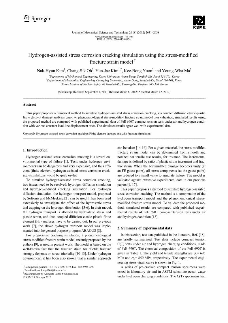
In this section, test data published in the literature, Ref. [18], are briefly summarized. Test data include compact tension C(T) tests under air and hydrogen charging conditions, made of FeE 690T. The chemical composition of the FeE 690T is given in Table 1. The yield and tensile strengths are σy = 695 MPa and σu = 850 MPa, respectively. The experimental engi-neering stress-strain curve is shown in Fig. 1.
A series of pre-cracked compact tension specimens were tested in laboratory air and in ASTM substitute ocean water under hydrogen charging conditions. The C(T) specimens had
2630 N.-H. Kim et al. / Journal of Mechanical Science and Technology 26 (8) (2012) 2631~2638
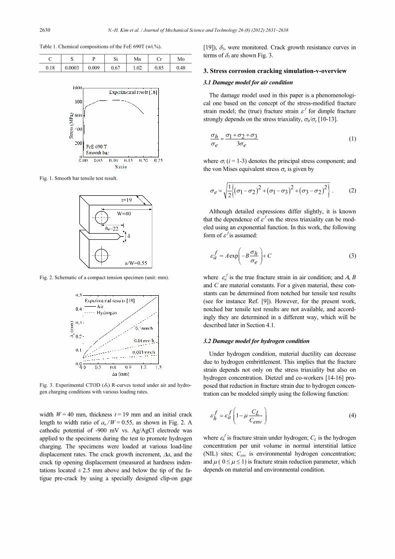
width W = 40 mm, thickness t = 19 mm and an initial crack length to width ratio of ao / W = 0.55, as shown in Fig. 2. A cathodic potential of -900 mV vs. Ag/AgCl electrode was applied to the specimens during the test to promote hydrogen charging. The specimens were loaded at various load-line displacement rates. The crack growth increment, Δa, and the crack tip opening displacement (measured at hardness inden-tations located ± 2.5 mm above and below the tip of the fa-tigue pre-crack by using a specially designed clip-on gage
[19]), δ5, were monitored. Crack growth resistance curves in terms of δ5 are shown Fig. 3.
The damage model used in this paper is a phenomenologi-cal one based on the concept of the stress-modified fracture strain model; the (true) fracture strain ε f for dimple fracture strongly depends on the stress triaxiality, σh/σe [10-13].
1 2 3
3he e
σ σ σ σσ σ
+ += (1)
where σi (i = 1-3) denotes the principal stress component; and the von Mises equivalent stress σe is given by
Although detailed expressions differ slightly, it is known
that the dependence of ε f on the stress triaxiality can be mod-eled using an exponential function. In this work, the following form of ε f is assumed:
expf hA B Cae
σε
σ⎛ ⎞
= − +⎜ ⎟⎜ ⎟⎝ ⎠
(3)
where εa
f is the true fracture strain in air condition; and Α, B and C are material constants. For a given material, these con-stants can be determined from notched bar tensile test results (see for instance Ref. [9]). However, for the present work, notched bar tensile test results are not available, and accord-ingly they are determined in a different way, which will be described later in Section 4.1.
3.2 Damage model for hydrogen condition
Under hydrogen condition, material ductility can decrease due to hydrogen embrittlement. This implies that the fracture strain depends not only on the stress triaxiality but also on hydrogen concentration. Dietzel and co-workers [14-16] pro-posed that reduction in fracture strain due to hydrogen concen-tration can be modeled simply using the following function:
1 Cf f Lah Cenvε ε μ
⎛ ⎞= −⎜ ⎟⎜ ⎟
⎝ ⎠ (4)
where εh
f is fracture strain under hydrogen; CL is the hydrogen concentration per unit volume in normal interstitial lattice (NIL) sites; Cenv is environmental hydrogen concentration; and μ ( 0 ≤ μ ≤ 1) is fracture strain reduction parameter, which depends on material and environmental condition.
Table 1. Chemical compositions of the FeE 690T (wt.%).
C S P Si Mn Cr Mo
0.18 0.0003 0.009 0.67 1.02 0.85 0.48
Fig. 1. Smooth bar tensile test result.
Fig. 2. Schematic of a compact tension specimen (unit: mm).
Fig. 3. Experimental CTOD (δ5) R-curves tested under air and hydro-gen charging conditions with various loading rates.
N.-H. Kim et al. / Journal of Mechanical Science and Technology 26 (8) (2012) 2631~2638 2631
3.3 Hydrogen diffusion model
Hydrogen is assumed to reside either at normal interstitial lattice sites (NILS) or reversible trapping sites generated by plastic straining. Oriani’s theory assumes local equilibrium between the two populations [20].
exp1- 1-θ θ WT L B=θ θ RTT L
⎛ ⎞⎜ ⎟⎝ ⎠
(5)
where θL is the occupancy of the interstitial sites, θT is the occupancy of the trapping sites, WB is the trap binding energy, R(= 8.31 J/mol) is gas constant, and T (in Kelvin) is the abso-lute temperature. The hydrogen concentration per unit volume in trapping sites, CT, can be expressed as
C NT T Tαθ= (6)
where α is the number of sites per trap and NT = NT(εp) de-notes the trap. The hydrogen concentrations are related to the number of sites, CL, can be expressed as
C NL L Lβθ= (7)
where β is the number of NILS per solvent atom and NL = NA/VM denotes the number of lattice sites per unit volume where NA = 6.0232 × 10²³ atoms/mol is Avogadro’s number and VM is the molar volume of the host lattice.
The governing equation for transient hydrogen diffusion ac-counting for trapping and hydrostatic drift as
2
03
CL D CL LtpD C V NL L H Tkk TRT tp
εσ αθε
∂− ∇ +
∂
∂ ∂⎛ ⎞∇ ⋅ ∇ + =⎜ ⎟ ∂ ∂⎝ ⎠
(8)
where t∂ ∂ is the time derivative, VH is the partial molar volume of hydrogen in solid solution, σij is the Cauchy stress, DL is the hydrogen diffusion constant through NILS,
( )1D D C Ceff L T L= + ∂ ∂ is an effective diffusion constant. It is known that the presence of hydrogen affects the elastic-
plastic constitutive law. To incorporate the hydrogen-induced lattice deformation, the total deformation rate tensor can be calculated by
pe hD D D Dij ij ij ij= + + (9)
where Dij
e, Dijp and Dij
h denote, respectively, the elastic, plastic and hydrogen parts. The hydrogen induced deformation rate Dij
h is purely dilatational and isotropic [2].
( )0ln 13
c c vdhD ijij dtσ
⎧ ⎫− Δ⎡ ⎤⎪ ⎪= +⎨ ⎬⎢ ⎥Ω⎪ ⎪⎣ ⎦⎩ ⎭ (10)
where ( )c C C NL T L= + is the total hydrogen concentration in NILS and trapping sites measured in H atoms per solvent atom, c0 is the initial hydrogen concentration in the absence of any straining, V NH AνΔ = is the volume change per hydro-gen atom introduced into solution, and Ω is the mean atomic volume of the host metal atom. The effective plastic strain εp
can be calculated by
2 / 3p pp D Dij ijε = ∫ . (11)
The above equations show that calculation of hydrogen dif-
fusion is fully coupled to the field of the hydrostatic stress and effective plastic strain, as calculation of plastic strains requires determination of hydrogen concentration.
3.4 Progressive failure simulation
Once the form of ε f is determined as a function of the stress triaxiality, incremental damage due to plastic deforma-tion, Δω, is calculated (at each gauss point within finite ele-ments) using
p
fεω
ε
ΔΔ = (12)
where Δεp is the equivalent plastic strain increment, calculated from FE analysis. When the accumulated damage becomes unity, ω = ΣΔω = 1, failure is assumed locally and incremental crack growth is simulated simply by reducing all stress com-ponents at the gauss point sharply to a small plateau value (typically less than 10MPa).
3.5 Implementation to ABAQUS
To implement constitutive equations for hydrogen diffusion (in Section 3.3), two user subroutines within ABAQUS are developed [7]. The first one is UMATHT for the hydrogen diffusion analysis, and the second one is UMAT to define a material’s mechanical behavior to incorporate deformation rate induced due to lattice straining by the solute hydrogen. Detailed information is given in Ref. [7].
To implement damage model and progressive failure simu-lation, described in Sections 3.2 and 3.4, the user subroutine UMAT is also used. The information on hydrogen concentra-tion at gauss points, which is calculated in UMATHT, is passed into the UMAT. The user subroutine UMAT calculates damage accumulation, according to Eq. (12). When the accu-mulated damage becomes critical (unity), stresses are relaxed simply by changing the yield surface. Note that in our previ-ous study [9], the user subroutine UHARD was used. How-ever, for the present work, the UHARD subroutine cannot be used due to coupled diffusion and elastic-plastic analysis, and
2632 N.-H. Kim et al. / Journal of Mechanical Science and Technology 26 (8) (2012) 2631~2638
accordingly the user subroutine UMAT is used by adding the hydrogen effect on fracture strain.
4. Fracture simulation under air condition
4.1 Determination of damage model and element size
To determine the stress-modified fracture strain model for FeE 690T, conventional elastic-plastic 3-D FE analyses (w/o damage) were first performed to simulate tensile tests of smooth bar. FE mesh for smooth bar is shown in Fig. 4(a). The number of elements is 6,258. Simulated result for smooth tensile test is compared with experimental tensile data in Fig. 4(b). The cross symbol in Fig. 4(b) indicates the failure initia-tion point in tests. The FE results can simulate deformation behavior well even after necking, but deviate from experimen-tal results after failure initiation points, as they cannot simulate failure. In Fig. 5(a), variation of the stress triaxiality with the equivalent plastic strain for the smooth tensile bar is shown. Both the stress triaxiality and equivalent plastic strain are ex-tracted in the center of the specimens, where failure initiation is expected to occur. Initially, the stress triaxiality in the center of the specimen is almost constant, but once necking develops, it increases with increasing equivalent plastic strain. As a fail-ure criterion should include the history of stress and strain, an average stress triaxiality is introduced, defined by
1
0
pf
ph h dpe eave f
εσ σ
εσ σε
⎛ ⎞=⎜ ⎟⎜ ⎟
⎝ ⎠∫ (13)
where εf
p denotes the equivalent plastic strain to failure initia-tion. Resulting equivalent plastic strain to failure initiation (called the fracture strain) for the smooth bar is shown in Fig.
5(b), as a function of the (average) stress triaxiality. To deter-mine the fracture strain εf, Eq. (3), however, we need two more points, as Eq. (3) includes three material constants. Although extra data points can be obtained using notched bar tensile test results, they are not available for the present prob-lem. At this point, it is worth noting that, based on semi-analytical approach, Rice and Tracey [13] suggested that the value of B can be approximated as B = -1.5, regardless of ma-terials. Even when the B value is fixed to B = -1.5, a complete form of the fracture strain cannot be determined. In the present work, it will be completed by comparing with the C(T) speci-men test results, as described next.
To determine the fracture strain as a function of the stress triaxiality, FE damage analysis of the C(T) test under air con-dition is performed using various choices of the stress-
(a)
(b)
Fig. 4. (a) FE mesh to simulate tensile test of the smooth bar; (b) com-parison of experimental engineering stress-strain data [18] with FE result.
(a)
(b)
Fig. 5. (a) Variations of the stress triaxiality with the equivalent plasticstrain for smooth bar tensile tests; (b) assumed fracture strain as a function of the stress triaxiality.
Fig. 6. FE mesh of the C(T) specimen for damage analysis.
N.-H. Kim et al. / Journal of Mechanical Science and Technology 26 (8) (2012) 2631~2638 2633
modified fracture strain. Various choices are made by assum-ing a point at the stress triaxiality of σh/σe = 2.5, which is the theoretical value for the Prandtl field [21] (see Fig. 5(b) for instance). Our experience indicates that the fracture strain at σh/σe = 2.5 ranges roughly from 10% to 20% of the uni-axial ductility for typical structural steels [9, 17]. Note that 10% of the uni-axial ductility corresponds to ~0.1 for the present ma-terial.
To perform FE damage analysis, an issue related to a finite element size needs to be resolved. An element size in FE damage analysis should be related to the micro-structural length scale, and thus is an important parameter. A typical FE mesh for the damage analysis is shown in Fig. 7. Four-node plane strain solid elements (element type CPE4) of the size Xmm x Xmm were uniformly spaced in the cracked section. Analysis was performed by systematically varying the ele-ment size X. To incorporate the large geometry change effect, the large geometry change option was chosen.
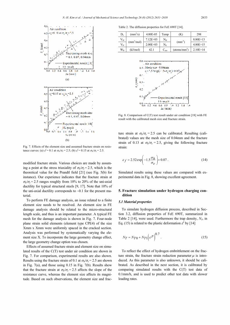
Effects of assumed fracture strain and element size on simu-lated results of the C(T) test under air condition are shown in Fig. 7. For comparison, experimental results are also shown. Results using the fracture strain of 0.1 at σh/σe = 2.5 are shown in Fig. 7(a), and those using 0.15 in Fig. 7(b). Results show that the fracture strain at σh/σe = 2.5 affects the slope of the resistance curve, whereas the element size affects its magni-tude. Based on such observations, the element size and frac-
ture strain at σh/σe = 2.5 can be calibrated. Resulting (cali-brated) values are the mesh size of 0.04mm and the fracture strain of 0.13 at σh/σe = 2.5, giving the following fracture strain:
2.52exp 1.5 0.07hfe
σε
σ⎛ ⎞
= − +⎜ ⎟⎜ ⎟⎝ ⎠
. (14)
Simulated results using these values are compared with ex-perimental data in Fig. 8, showing excellent agreement.
5. Fracture simulation under hydrogen charging con-
dition
5.1 Material properties
To simulate hydrogen diffusion process, described in Sec-tion 3.2, diffusion properties of FeE 690T, summarized in Table 2 [14], were used. Furthermore the trap density, NT, in Eq. (15) is related to the plastic deformation εp by [14]
( )0.70 1
pN N NT T T ε= + . (15)
To reflect the effect of hydrogen embrittlement on the frac-
ture strain, the fracture strain reduction parameter μ is intro-duced. As this parameter is also unknown, it should be cali-brated. As described in the next section, it is calibrated by comparing simulated results with the C(T) test data of 0.1mm/h, and is used to predict other test data with slower loading rates.
(a)
(b)
Fig. 7. Effects of the element size and assumed fracture strain on resis-tance curves: (a) εf = 0.1 at σh/σe = 2.5; (b) εf = 0.15 at σh/σe = 2.5.
Table 2. The diffusion properties for FeE 690T [14].
DL (mm2/s) 4.00E-05 Temp (K) 298
VM 7.12E+03 Nt0 8.80E+13
VH(mm3/mol)
2.00E+03 Nt1 (mm-3)
4.80E+15
WB (kJ/mol) 42.1 Cenv (atoms/mm3) 2.10E+14
Fig. 8. Comparison of C(T) test result under air condition [18] with FE result with the calibrated mesh size and fracture strain.
2634 N.-H. Kim et al. / Journal of Mechanical Science and Technology 26 (8) (2012) 2631~2638
5.2 FE analysis and boundary conditions
The FE damage analysis for the C(T) specimens under hy-drogen environments with different loading rates is performed using ABAQUS. Two-dimensional FE damage analysis was performed using four-node quadrilateral elements (CPE4 for ductile failure simulation and CPE4T for hydrogen assisted SCC simulation) to simulate the test under hydrogen condi-tions with different loading rates. To incorporate the large geometry change effect, the large geometry change option was chosen.
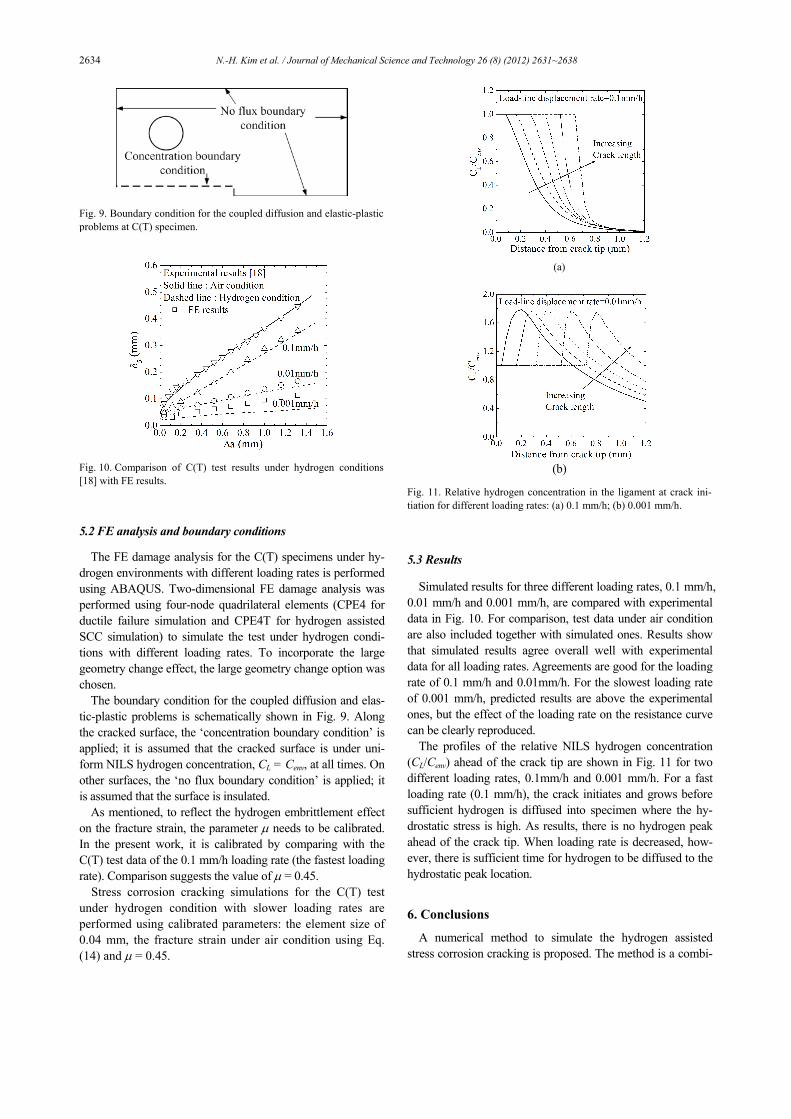
The boundary condition for the coupled diffusion and elas-tic-plastic problems is schematically shown in Fig. 9. Along the cracked surface, the ‘concentration boundary condition’ is applied; it is assumed that the cracked surface is under uni-form NILS hydrogen concentration, CL = Cenv, at all times. On other surfaces, the ‘no flux boundary condition’ is applied; it is assumed that the surface is insulated.
As mentioned, to reflect the hydrogen embrittlement effect on the fracture strain, the parameter μ needs to be calibrated. In the present work, it is calibrated by comparing with the C(T) test data of the 0.1 mm/h loading rate (the fastest loading rate). Comparison suggests the value of μ = 0.45.
Stress corrosion cracking simulations for the C(T) test under hydrogen condition with slower loading rates are performed using calibrated parameters: the element size of 0.04 mm, the fracture strain under air condition using Eq. (14) and μ = 0.45.
5.3 Results
Simulated results for three different loading rates, 0.1 mm/h, 0.01 mm/h and 0.001 mm/h, are compared with experimental data in Fig. 10. For comparison, test data under air condition are also included together with simulated ones. Results show that simulated results agree overall well with experimental data for all loading rates. Agreements are good for the loading rate of 0.1 mm/h and 0.01mm/h. For the slowest loading rate of 0.001 mm/h, predicted results are above the experimental ones, but the effect of the loading rate on the resistance curve can be clearly reproduced.
The profiles of the relative NILS hydrogen concentration (CL/Cenv) ahead of the crack tip are shown in Fig. 11 for two different loading rates, 0.1mm/h and 0.001 mm/h. For a fast loading rate (0.1 mm/h), the crack initiates and grows before sufficient hydrogen is diffused into specimen where the hy-drostatic stress is high. As results, there is no hydrogen peak ahead of the crack tip. When loading rate is decreased, how-ever, there is sufficient time for hydrogen to be diffused to the hydrostatic peak location.
6. Conclusions
A numerical method to simulate the hydrogen assisted stress corrosion cracking is proposed. The method is a combi-
Fig. 9. Boundary condition for the coupled diffusion and elastic-plastic problems at C(T) specimen.
Fig. 10. Comparison of C(T) test results under hydrogen conditions [18] with FE results.
(a)
(b)
Fig. 11. Relative hydrogen concentration in the ligament at crack ini-tiation for different loading rates: (a) 0.1 mm/h; (b) 0.001 mm/h.
N.-H. Kim et al. / Journal of Mechanical Science and Technology 26 (8) (2012) 2631~2638 2635
nation of the hydrogen transport model and the phenomenol-ogical stress-modified fracture strain model. The hydrogen transport model of Sofronis and McMeeking [2] was used to simulate the effect of the hydrostatic stress and trapping on the hydrogen distribution. For progressive cracking simulation, a phenomenological stress-modified fracture strain model is used, proposed by the authors [9]. The model is based on the fact that the fracture strain for ductile fracture strongly de-pends on stress triaxiality. The hydrogen embrittlement effect on the fracture strain is incorporated in a simple form.
The proposed method is validated by comparing with pub-lished experimental data of stress corrosion cracking testing of FeE 690T C(T) tests under air and hydrogen condition. In hydrogen condition, the specimens were subjected to three different loading rates. The simulated results agree well with experimental data.
Acknowledgment
This work is supported by the MEST/KOSEF (Nuclear R&D Program, M2060608000208M060800210), funded by Korea Science & Engineering Foundation.
A, B, C : Material constants in Eq. (3) a, ao, Δa : Crack length, initial value and its increment Cenv : Environmental hydrogen concentration CT, CL : Hydrogen concentration per unit volume in trap-
ping sites and in NILS, respectively DL : Hydrogen diffusion constant through NILS Deff : Effective diffusion constant NA : Avogadro's number (6.0232x10²³) NT : Trap density measured in number of traps per
unit volume NL : Number of solvent lattice atoms per unit lattice
volume NILS : Normal interstitial lattice site R : Gas constant (= 8.31J/mol/K) T : Absolute temperature (K) VH : Partial molar volume of hydrogen in solid solu-
tion VM : Molar volume of the host lattice measured in
units of volume per lattice mole WB : Trap binding energy δ5 : Crack-tip opening displacement measured using
the 5 mm clip gage εp, Δεp : Equivalent plastic strain and its increment εa
f, εhf : Fracture strain under air and hydrogen conditions,
respectively μ : Fracture strain reduction parameter, see Eq. (4) σe, σh : Effective stress and hydrostatic stress, respec-
tively, see Eqs. (1) and (2) σ1, σ2, σ3 : Principal stress components ω, Δω : Accumulated damage and incremental damage
References
[1] J. P. Hirth, Effect of hydrogen in the properties of iron steel, Metallurgical and Materials Transactions A, 11 (6) (1980) 861-890.
[2] P. Sofronis and R. M. McMeeking, Numerical analysis of hydrogen transport near a blunting crack tip, Journal of the mechanics and Physics of Solids, 37 (3) (1989) 317-350.
[3] H. K. Birnbaum and P. Sofronis, Hydrogen-enhanced local-ized plasticity-a mechanism for hydrogen related fracture, Material Science and Engineering A, 174 (1994) 191-202.
[4] A. Taha and P. Sofronis, A micromechanics approach to the study of hydrogen transport and embrittlement, Engineering Fracture Mechanics, 68 (2001) 803-837.
[5] J. Lufrano, P. Sofronis and H. K. Birnbaum, Elastoplasti-cally accommodated hydride formation and embrittlement, Journal of Mechanics and Physics of Solids, 46 (1998) 1497-1520.
[6] Y. Liang, P. Sofronis and R. H. Dodds Jr., Interaction of hydrogen with crack-tip plasticity: effects of constraint on void growth, Material Science and Engineering A, 366 (2004) 397-411.
[7] C. S. Oh, Y. J. Kim and K. B. Yoon, Coupled analysis of hydrogen transport using ABAQUS, Journal of Solid Me-chanics and Materials Engineering, 4 (7) (2010) 908-917.
[8] ABAQUS Version 6.7. User’s manual, Dassault Systemes, 2008.
[9] C. S. Oh, N. H. Kim, Y. J. Kim, J. H. Beak, Y. P. Kim and W. S. Kim, A finite element ductile failure simulation meth-od using stress-modified fracture strain model, Engineering Fracture Mechanics, 78 (2011) 124-137.
[10] F. A. McClintock, A criterion of ductile fracture by the growth of holes, ASME J Appl. Mech., 35 (1968) 363-371.
[11] A. C. Mackenzie, J. W. Hancock and D. K. Brown, On the influence of state of stress on ductile failure initiation in high strength steels, Engineering Fracture Mechanics, 9 (1977) 167-188.
[12] J. W. Hancock and M. J. Cowling, Role of state of stress in crack-tip failure processes, Material Science and Technology, (1980) 293-304.
[13] J. R. Rice and D. M. Tracey, On the ductile enlargement of voids in triaxial stress fields, Journal of the mechanics and Physics of Solids, 17 (1969) 201-217.
[14] M. Pfuff and W. Dietzel, Mesoscale modelling of hydrogen assisted crack growth in heterogeneous materials. In: Carpin-teri A, editor, Proceedings of the 11th international confer-ence on fracture, Turin (Italy) (2005).
[15] W. Dietzel, M. Pfuff and G. G. Juilfs, Hydrogen permea-tion in plastically deformed steep membranes, Material sci-ence, 42 (2006) 78-84.
[16] W. Dietzel and M. Pfuff, The effect of deformation rates on hydrogen embrittlement. In: Thomson AW, Moody NR, edi-tors, Hydrogen effects in materials, The minerals and Mate-rials Society (1996) 303-311.
[17] N. H. Kim, C. S. Oh, Y. J. Kim, K. B. Yoon and Y. H. Ma,
2636 N.-H. Kim et al. / Journal of Mechanical Science and Technology 26 (8) (2012) 2631~2638
Comparison of fracture strain based ductile failure simula-tion with experimental results, International Journal of Pressure Vessels and Piping, 88 (2011) 434-447.
[18] I. Scheider, M. Pfuff and W. Dietzel, Simulation of hydro-gen assisted stress corrosion cracking using the cohesive model, Engineering Fracture Mechanics, 75 (2008) 4283-4291.
[19] D. Hellmann and K. H. Schwalbe, On the experimental determination of CTOD based R-Curves, The crack tip opening displacement in elastic-plastic fracture mechanics, K.-H. Schwalbe ed. Springer Verlag, Berlin-Heidelberg-New York (1986) 115-132.
[20] R. A. Oriani, The diffusion and trapping of hydrogen in steel, Acta Metallurgica, 18 (1970) 147-57.
[21] T. Anderson, Fracture Mechanics Fundamentals and Ap-plications, 3rd edition, CRC Press (2005).
Nak-Hyun Kim received a B.S. degree in Mechanical Engineering from Korea University in 2008. He is currently in the doctoral course of the Graduate School of Korea University. His re-search interests are in damage mechan-ics and hydrogen embrittlement.
Yun-Jae Kim is a professor of the Me-chanical Engineering Department, Ko-rea University, Seoul, Korea. He re-ceived his Ph.D in 1993 from Massa-chusetts Institute of Technology, USA. His research interests are in structural integrity and reliability.