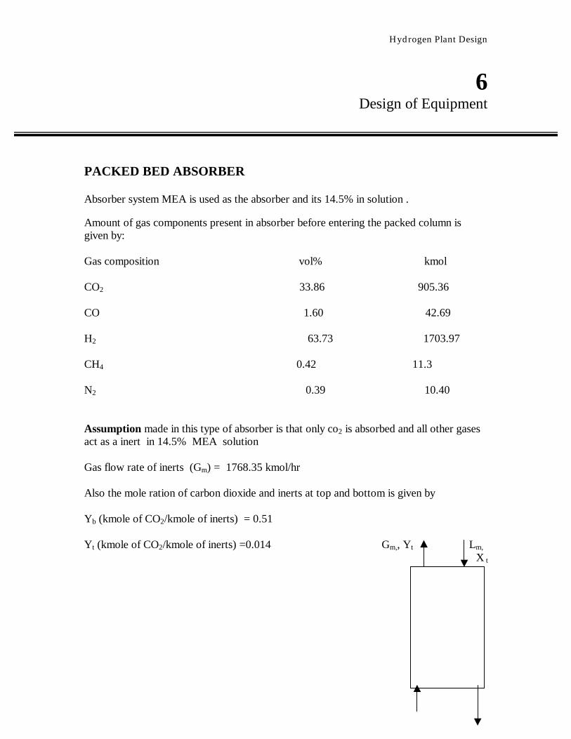
Hydrogen Plant Design 6 Design of Equipment PACKED BED ABSORBER Absorber system MEA is used as the absorber and its 14.5% in solution . Amount of gas components present in absorber before entering the packed column is given by: Gas composition vol% kmol CO 2 33.86 905.36 CO 1.60 42.69 H 2 63.73 1703.97 CH 4 0.42 11.3 N 2 0.39 10.40 Assumption made in this type of absorber is that only co 2 is absorbed and all other gases act as a inert in 14.5% MEA solution Gas flow rate of inerts (G m ) = 1768.35 kmol/hr Also the mole ration of carbon dioxide and inerts at top and bottom is given by Y b (kmole of CO 2 /kmole of inerts) = 0.51 Y t (kmole of CO 2 /kmole of inerts) =0.014 G m, , Y t L m, X t
Transcript
Hydrogen Plant Design
6 Design of Equipment
PACKED BED ABSORBER Absorber system MEA is used as the absorber and its 14.5% in solution . Amount of gas components present in absorber before entering the packed column is given by: Gas composition vol% kmol CO2 33.86 905.36 CO 1.60 42.69 H2 63.73 1703.97 CH4 0.42 11.3 N2 0.39 10.40 Assumption made in this type of absorber is that only co2 is absorbed and all other gases act as a inert in 14.5% MEA solution Gas flow rate of inerts (Gm) = 1768.35 kmol/hr Also the mole ration of carbon dioxide and inerts at top and bottom is given by Yb (kmole of CO2/kmole of inerts) = 0.51 Yt (kmole of CO2/kmole of inerts) =0.014 Gm,, Yt Lm,
X t
Hydrogen Plant Design
By carbon dioxide balance we get Gm(Yb – Yt) = Lm(Xb – Xt) Assuming a pure MEA solution is used for absorbtion Therefore Xt=0 We get LmXb = 877.10 kmol/hr
Now from graph (Lm/Gm)min = 0.508 also (Lm/Gm)actual = (1.1 to 1.5 times)(Lm/Gm)min now assuming (Lm/Gm)actual = 1.25X(Lm/Gm)min (Lm/Gm)actual = 1.25X0.508 =0.6375 also Gm =1768.35 kmol/h Lm=1768.35X0.6375=1127.32 kmol/hr But the amount obtained is only of MEA , thus amount of solution is given by Lm=1127.32/14.5 X10-2 =7774.64 kmol/hr From above equation we get Xb =0.113
Hydrogen Plant Design
Column diameter calculation: Gb = 44910.82 kg/hr Gb = 12.48 kg/sec Lb= Lm X 24.25 + 877.10 X 44 Lb =227127.42 kg/hr = 63.09 kg/sec Also calculated density of gases and liquids are For liquid ρliq =992.06 kg/m3 µ =0.9 cp(from perry) for gases ρgas=0.626 kg/m3
Let us choose ,Intalox saddles ,ceramic as packing material From table 18-5 ,page 18-23, of perry We get Dp= 38 mm ε =0.80 Specific surface area =195 m2/m3 Fp=170 Now we have L/G x (ρg/ρl)
1/2 = (63.09/12.48)X(0.626/992.06)0.5 = 0.126 Where L =liquid mass rate ,kg/(m2.s) G =Gas mass rate,kg/(s.m2) Also from fig 18- 38, page 18-22 of perry
Hydrogen Plant Design
We get G2 Fp Ψ µ0.2 = 0.14 ρg ρl g where G =Superficial mass flow rate of the gas kg/s.m2 U =superficial gas velocity,m/s Ap= Total area of packing ,m2/m3(bed) ε =fractional void in dry packing ρl and ρg=liquid and gas density,kg/m3 µl= liquid viscosity ,cP therefore we get Gf =2.275 kg/(s.m2) Gas flow rate of bottom is fixed so that the cross section can be calculated. For this we have to operate below the flooding limit, thus G we choose should Be 60-85% of Gf Also we have Ac= Gb/(0.85XGf) m
2
Ac = 6.45 m2 Also to ensure, there is proper wetting column diameter should be at least 10 times
greater then packing diameter and above value of column diameter satisfies the
given condition.
Dc = 2.866m
Hydrogen Plant Design
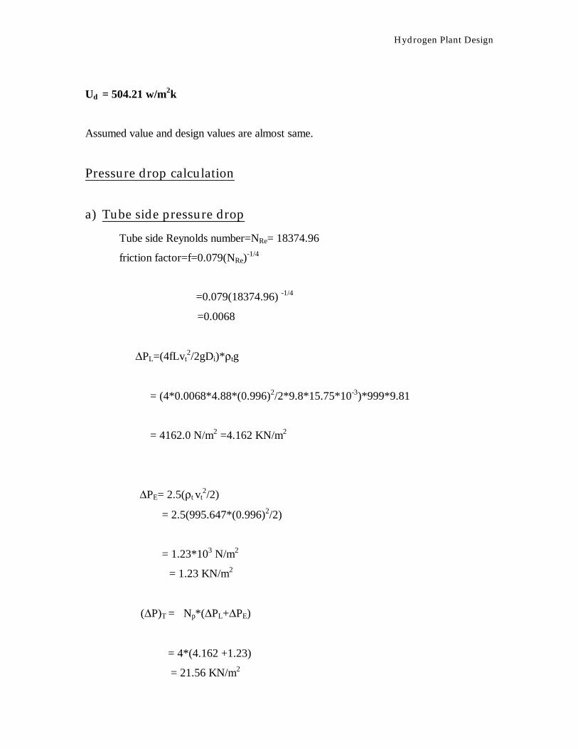
Pressure drop calculation This is calculated using the formula’s from perry ∆P = C2 x (10C
3Utl ) x ρg X (Utg)2
where ∆P=in H2O/ft packing ρg = gas density ,lb/ft3
Ut and ut =superficial velocities of gas and liquid respectively C2 and C3 = constant given in table now we have L =63.09/6.45 =9.77kg/sec.m2 =7204.398 lb/hr.ft2 G =12.48/6.45 = 1.93 =1423.18 lb/hr.ft2 Utg=1.93/0.626 =3.08 m/s =10.10 ft/sec Utl = 9.77/992.06 =9.85X10-3=0.0323 ft/sec Also from table 18-7we get C2=0.14 C3=0.0181 ∆P = (0.14)X(10)0.0181x0.0323X(10.10)2X0.039 ∆P =0.5577 in water/ft packing = 46.44 mm Hg water/m packing The height of tower is not known therefore total pressure drop cannot be calculated
Hydrogen Plant Design
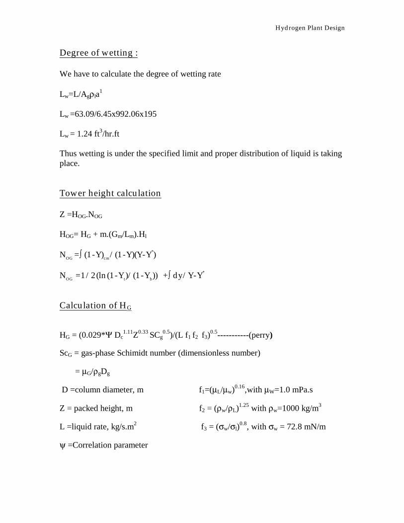
Degree of wetting : We have to calculate the degree of wetting rate Lw=L/Agρla
1 Lw =63.09/6.45x992.06x195 Lw = 1.24 ft3/hr.ft Thus wetting is under the specified limit and proper distribution of liquid is taking place. Tower height calculation Z =HOG.NOG HOG= HG + m.(Gm/Lm).Hl
NOG =∫ (1-Y)cm/(1-Y)(Y-Y*) NOG =1/2(ln(1-Yt)/(1-Yb)) +∫ dy/Y-Y*
Calculation of HG
HG = (0.029*Ψ Dc1.11Z0.33 SCg
0.5)/(L f1 f2 f3)0.5-----------(perry)
ScG = gas-phase Schimidt number (dimensionless number)
= µG/ρgDg
D =column diameter, m f1=(µL/µw)0.16,with µW=1.0 mPa.s
Z = packed height, m f2 = (ρw/ρL)1.25 with ρw=1000 kg/m3
L =liquid rate, kg/s.m2 f3 = (σw/σl)0.8, with σw = 72.8 mN/m
ψ =Correlation parameter
Hydrogen Plant Design
From calculation we get
f1= 1.0016 f3 = 1.06
f2 = 1.01 µl =.09 cP
also for %flood = 85 we have ψ = 65
and Dmix=0.640 cm2/sec (calculated by assuming a binary mix of CO2 and H2)
ScG =0.2496
Substituting in above equation we get
HG = (Z)0.33 x 0.977
Calculation of HL
HL =(φC/3.28)X(µL/ρLDL)0.5X(Z/3.05)0.15
φ = Correlation parameter for given packing, m
C = correlation factor for high gas rates ( fig 18-59)
µL =liquid viscosity , Pa.s
ρL =Liquid density , kg/m3
DL =liquid –diffusion coefficient, m2/s
Z =height of packing,m
From property calculation we get :
φ = 0.023 µL =0.90 cP
ρL =992.06 C = 0.48 (from fig 18-59, perry)
we get
HL = 0.061(Z)0.15
Hydrogen Plant Design
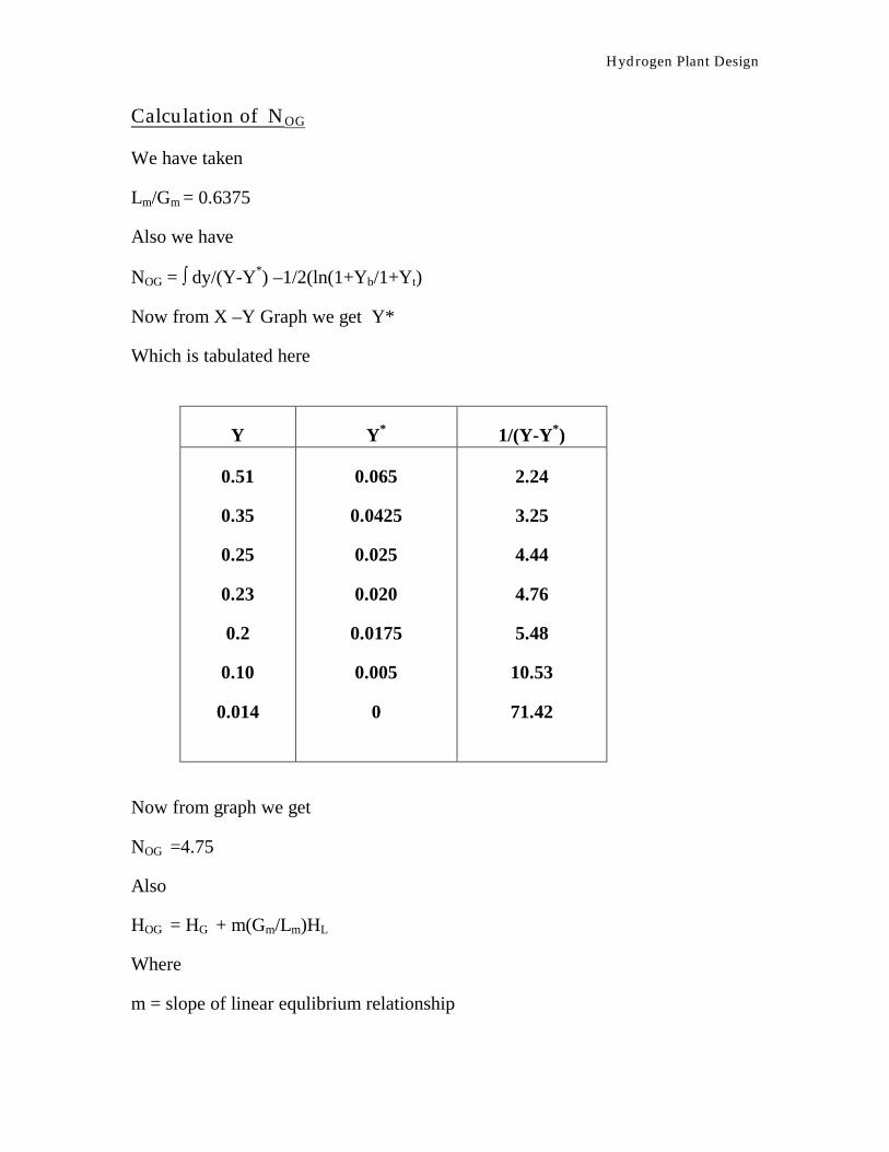
Calculation of NOG
We have taken
Lm/Gm = 0.6375
Also we have
NOG = ∫ dy/(Y-Y*) –1/2(ln(1+Yb/1+Yt)
Now from X –Y Graph we get Y*
Which is tabulated here
Y Y* 1/(Y-Y*)
0.51
0.35
0.25
0.23
0.2
0.10
0.014
0.065
0.0425
0.025
0.020
0.0175
0.005
0
2.24
3.25
4.44
4.76
5.48
10.53
71.42
Now from graph we get
NOG =4.75
Also
HOG = HG + m(Gm/Lm)HL
Where
m = slope of linear equlibrium relationship
Hydrogen Plant Design
therefore HOG ={ (Z)0.33(0.977) +(0.05)(Z)0.15} Also we get Z = (4.75){ (Z)0.33(0.977) +(0.05)(Z)0.15} Calculating above equation we get Z =10.4 m
Height of Absorber = 10.4 m
Hydrogen Plant Design
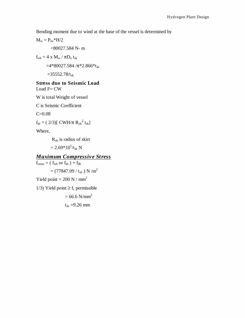
MECHANICAL DESIGN OF ABSORBER Material for shell is Carbon Steel
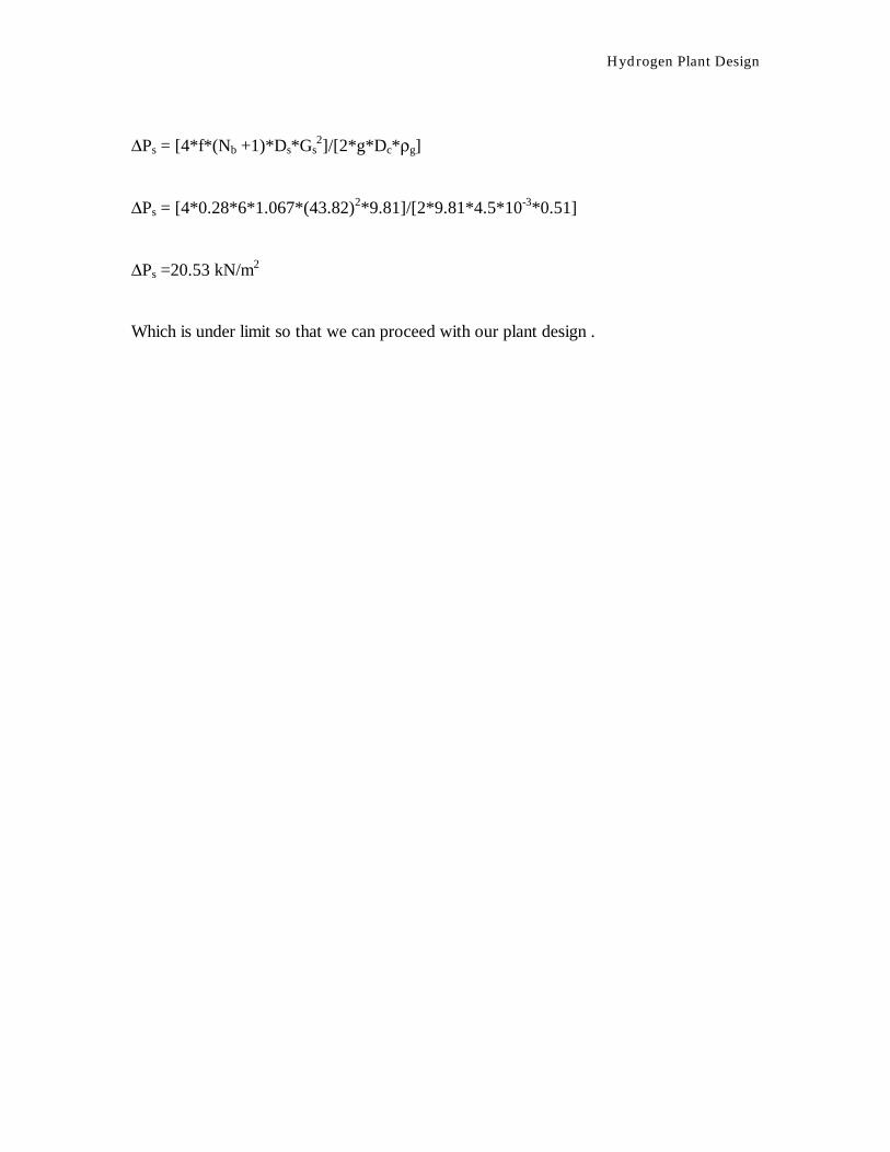
Which is under limit so that we can proceed with our plant design .
Hydrogen Plant Design
MECHANICAL DESIGN OF SHELL AND TUBE HEAT EXCHANGER Carbon Steel (Corrosion allowance 3 mm)
SHELL SIDE Number of shell =1
Number of pass =4
Fluids in shell are Hydrogen, Carbon dioxide, carbon monooxide, Methane and Nitrogen
Design pressure =1.064 x10 5 N /m2 =0.11N/mm2
Temperature of inlet =250oC
Temperature of outlet = 25oC
Permissible Stress for carbon steel (f)= 95 N/mm2
Segmental baffle cut with tie rods and spacers
TUBE SIDE Tube and sheet material --------- Stainless steel
No. of tubes =1388
Outside Diameter =19.05mm
Inside Diameter =15.75mm
Length =4.88m
Pitch ∆lr =1inch
Fluid = Water
Working pressure =1atm =0.1N/mm2
Design pressure =0.11N/mm2
Inlet temperature = 200C
Outlet temperature =400C
SHELL SIDE:
Hydrogen Plant Design
SHELL SIDE DIAMETER Shell Diameter =1067mm
Shell thickness ts= pd/2fj +p
where j=85%
= 0.11*1067/(2*95*0.85 +0.11)
=0.73mm
From IS-4503 Table (4) gives a minnimum thickness of 6.3 including corrosion
allowance .Use 10.0 mm thickness.
HEAD THICKNESS Consider Shallow dished and torespherical head
th=P*Rc*W/(2*f*j)
Where j=0.85 Rc = Crown radius
W =stress intensification factor
RK = knuckle radius
RK = 6%Rc
W=1/4*(3+ (RC/RK)1/2) = 1.77
th= 0.11*1067*1.77/2*95
== 1.09mm
Use thickness same as for shell , i.e. 10mm including corrosion allowance.
TRANSVERSE BAFFLES Spacing baffles = DS = 1067mm
Number of baffles = 4.88/1.067 =5
But in process design Number of baffles is assumed to be 3
So that pressure drops comes under the given limit
Thickness of baffles =6mm
Hydrogen Plant Design
TIE RODS AND SPACERS Tie Rods and Spacers shall be provided to retain all cross baffles and tube support heater
accurately.
Diameter of rod =15mm
No. of the rod =6mm
Following is from bhattacharya
FLANGES Design Pressure =0.11MN/m2
Flange material =IS:2004 ------1962 class2
Bolting Steel = 5% Cr Mo Steel
Gasket material = Asbestos composition
Shell diameter =1067mm
Shell thickness=10mm
Outside diameter = 1087mm
Allowable stress of flange material =100MN/m2
Allowable stress for bolting material =138 MN/m2
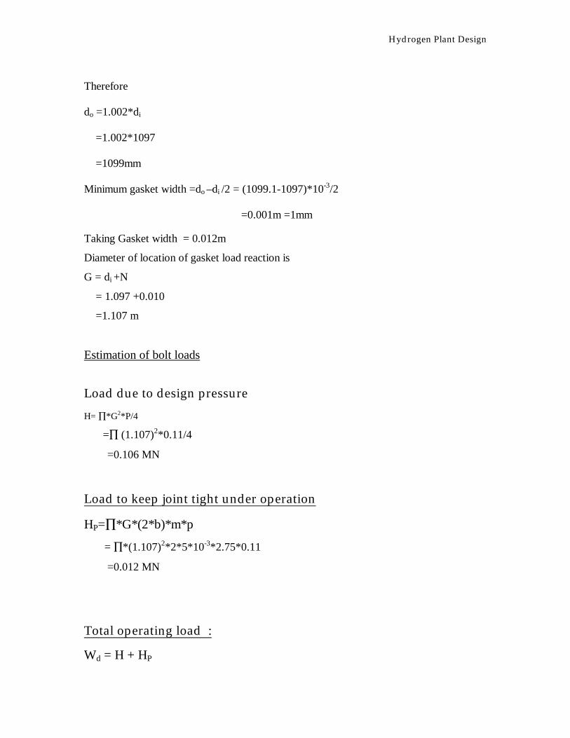
dO/di =(y-Pm)/( y-pm) where m =gasket factor y= min design seating stress MN/m2 assuming gasket thickness of 1.6mm y=25.5 m= 2.75…………… from IS 2825-1969 do/di =[(25.5-0.11*2.75)/(25.5-0.11(2.75 +1)]1/2 do/di =1.002 let dI of the gasket equal to 1097mm , 10mm greater than Shell diameter.