On the other hand, the fracture surfaces of the Al-Mg-Si-Cr alloy suggest the occurrence of a typical HE phenomenon. In the case of DNG, there is no IGC near the fatigue crack initiation site (Fig. 7-(c)). However, under RH90%, an IGC region of a considerably large area extends around the crack initiation site (Fig. 7-(d)). The fact that the Al-Mg-Si-Cr alloy exhibits no IGC under DNG despite the presence of just a little IGC under DNG in the Al-Mg-Si-Cu alloy having lower HE sensitivity may be attributed to difference in grain sizes between the two alloys as shown in Fig. 2. Resistance to the occurrence of IGC increases with grain size independently of HE sensitivity, and thus the Al-Mg-Si-Cr alloy which has a finer grain structure is interrupted to have exhibited no IGC under the milder DNG condition. Whereas, the fracture surfaces of the Al-Mg-Si-Fe alloy present IGC regions near their crack initiation sites under both DNG and RH90% conditions, and an IGC area under RH90% is lager than that under DNG.The same trends were recognized for the ternary Al-Mg-Si alloy (Fig. 4). This result can be attributed to the following common features between the Al-Mg-Si and the Al-Mg-Si-Fe alloys: high HE sensitivity due to their Cu-free compositions and low resistance to IGC due to their coarse grain structures.
4. Summary In order to examine intrinsic hydrogen embrittlement behavior of 6XXX-series aluminum alloys
during fatigue fracture, the ternary Al-Mg-Si alloy was subjected to the fatigue test under controlled experimental humidity with the comparison AA6061 alloy of the same Mg and Si compositions. Additionally, the effect of additive elements such as Cu, Cr and Fe to the ternary alloy on a hydrogen embrittlement (HE) behavior was examined. The following results were obtained. 1. Although the effect of experimental humidity on the 6061 alloy was not so significant, the cyclic
lives of the Al-Mg-Si alloy clearly decreased with experimental humidity. This suggested that the Al-Mg-Si alloy exhibited HE by hydrogen atoms intruded from experimental environment.
2. The fracture surface of the Al-Mg-Si alloy showed brittle intergranular cracking (IGC) near its fatigue crack initiation site, and the area of the IGC region increased with the experimental humidity. From these results, the decrease in cyclic lives of the Al-Mg-Si alloy with the experimental humidity was probably attributed to accelerated fatigue crack growth at its early growth stage by the occurrence of IGC near the crack initiation site.
3. Only Cu exhibited the effect of decreasing the HE sensitivity of the Al-Mg-Si alloy in the fatigue fracture among the additive elements examined, Cu, Cr and Fe. The addition of Cu inhibited the occurrence of IGC near the crack initiation site and showed as long cyclic lives under RH90% as under DNG.
References [1] G. A. Young Jr., J. R. Scully: Metal. and Mater. Trans. A, 33A (2002), 101-115. [2] S. Osaki, H. Kondo and K. Kinoshita: Mater. Trans., 47(2006), 1127-1134.
Proceedings of the 12th International Conference on
Aluminium Alloys, September 5-9, 2010, Yokohama, Japan
©2010 The Japan Institute of Light Metals
Hydrogen Evolution during Fatigue Deformation in 6061 and 7075 Aluminum
Alloys
Keitaro Horikawa1, Hiroyuki Yamada
2 and Hidetoshi Kobayashi
1
1School of Engineering Science, Osaka University, 1-3 Machikaneyama, Toyonaka, Osaka, 560-8531, Japan 2Graduate Student, School of Engineering Science, Osaka University,
1-3 Machikaneyama, Toyonaka, Osaka, 560-8531, Japan
Hydrogen evolution behavior during fatigue deformation and fracture in 6061 and 7075
aluminum alloys was examined by using a testing machine equipped with a quadrupole mass
spectrometer in an ultrahigh vacuum chamber (QMS-UHV) and by a hydrogen microprint
technique (HMT). The QMS-UHV testing revealed that hydrogen was highly evolved at the first
cycle in the plastic fatigue. This assumed that hydrogen atoms primarily dissolved were transported
to the surface during deformation. It was also revealed that hydrogen evolution behavior in the early
stage of plastic fatigue corresponded well with the variation of the applied stress. The amount of
hydrogen evolution then decreased according to the number of fatigue cycles. The amount of
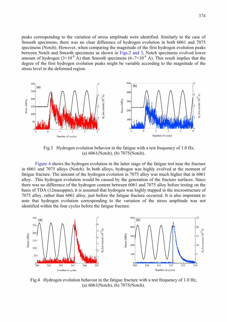
hydrogen evolved at the fatigue fracture was different from the alloy types; the hydrogen evolution
of 7075 alloys was much higher than that of 6061 alloys. The HMT after the fatigue test also
revealed that silver particles, which represented the emission sites of hydrogen, were observed
mainly around the second phase inclusions.
Keywords: Hydrogen, Fatigue, Deformation, Mass spectrometry, Hydrogen microprint
1. Introduction
Aluminum alloys have been regarded as one of the candidate materials for a high compressed
(~35MPa) hydrogen tank in the fuel cell vehicles [1,2], since the aluminum alloys show high
resistance to hydrogen embrittlement rather than the steels. Among the industrial aluminum alloys,
Al-Mg-Si (6000 series) and Al-Zg-Mg (7000 series) ones are believed to be the promising materials
for the tank liner. However, the 6000 and 7000 series aluminum alloys are reported to exhibit
environmental embrittlement when tested at slow strain rates in laboratory air [3–9] in recent years.
This phenomenon is believed to be a kind of hydrogen embrittlement (HE) caused by atmospheric
hydrogen. Considering the direction for use of the aluminum alloys as a high compressed hydrogen
gas container, it will be important to clarify the fatigue properties of aluminum alloys affected by
atmospheric hydrogen to guarantee the safety of the tank. In this study, from a basic point of view,
fatigue test was performed by using a testing machine which is equipped with a quadrupole mass
spectrometer installed in an ultrahigh vacuum (QMS-UHV) chamber [10,11], together with a
hydrogen microprint technique (HMT) [12] to visualize the hydrogen evolution behavior of 6061
and 7075 aluminum alloys.
2. Experimental
2.1 Materials
The materials used in the present study were 6061 and 7075 aluminum alloys; its chemical
composition is shown in Table 1. Plate test specimens for the fatigue test with a gage length of 10
mm, width of 5 mm, fillet radius of 1 mm, and thickness of 1.0 mm were cut from a rolled sheet
(Smooth). Double U-notched test pieces having a depth of 0.5 mm, a diameter of the notch root of
0.27 mm were also machined on the basis of the dimension of Smooth specimen to fix the fracture
zone (Notch). The 6061 alloy specimens were solution treated at 530 ˚C for 20 min and quenched in
371Proceedings of the 12th International Conference on Aluminium Alloys, September 5-9, 2010, Yokohama, Japan©2010 The Japan Institute of Light Metals pp. 371-376
water, and then aged at 160 ˚C for 18 h (T6-temper). The 7075 alloy specimens were solution
treated at 493 ˚C for 20 min and quenched in water, and then aged at 120 ˚C for 24 h (T6-temper).
In all the test specimens, both surfaces were polished by emery papers (#800 and #1200) and buffed
with alumina pastes to obtain a mirror-finished surface. The fatigue test to determine the relation
between the stress and the number of failure was conducted by using the double U-notched test
pieces at the frequency of 1.0 Hz and the stress ratio of 0.1 with the constant stress amplitude with a
relative humidity of 50% (RH50%) or 90 % (RH90%). The amount of hydrogen gas contained in
the specimens was measured by thermal deposition analysis (TDA) using gas chromatography. For
TDA, a highly pure argon carrier gas (99.999 % purity) was passed through a quartz glass tube that
contained the test specimen at a flow rate of 20 mL / min. The amount of hydrogen gas was
measured at 1 min intervals while the specimen was heated to 600 ˚C. The specimen weighed about
0.45 g and the heating rate was 100 °C / h.
2.2 Hydrogen desorption analysis in the fatigue test
Prior to the test, the specimen was placed on the jig of the tensile testing apparatus equipped
with a QMS installed in the UHV chamber. The fatigue test of the specimens was carried out 24 h
after maintaining the specimens in a UHV atmosphere in order to obtain a vacuum level of 7.0 ×
10–7
Pa. In this study, the baking operation for the UHV chamber was not performed in order to
carry out the fatigue test under the constant ambient temperature. The hydrogen evolution from the
specimen was evaluated from the hydrogen ion current, where the mass number M/e=2 was selected.
The QMS-UHV fatigue test was carried out at the frequency of 1.0 Hz or 0.1 Hz and the stress ratio
of 0.1 with the constant stress amplitude. The applied maximum stresses were selected to become
slightly higher than the yield stress of 6061 or 7075 alloy specimens.
2.3 HMT
In the HMT, before the testing, the mirror-finished surface was covered with a collodion layer
to prevent the reduction of Ag+ to Ag by aluminum atoms. The collodion layer was then covered
with a liquid nuclear emulsion (Ilford L-4, diluted with pure water) containing gelatin and silver
bromide (AgBr) crystals using a wire loop method and dried for 15 min. The specimens were
fatigue-deformed in laboratory air. The fatigue tests with the HMT were performed in the same
testing conditions as the QMS-UHV testing, except for the testing atmosphere of air. After the
fracture, the specimens were removed from the testing machine and dipped into formalin (37
mass% HCHO water solution) after the tensile test for 3 s to harden the gelatin layer; then, the
specimens were immersed in a fixing solution (15 mass% Na2S2O3 water solution) for 8 min to
remove the remaining silver bromide particles that did not react with the hydrogen atoms. The
arrangement of the silver particles was observed using a scanning electron microscope (SEM)
equipped with an energy dispersive X-ray spectrometer (EDXS).
3. Results and discussion
3.1 S-N curves
Table 1 Chemical compositions of 6061 and 7075 aluminum alloys (mass%)
Alloy Si Fe Cu Mn Mg Cr Zn Ti Al
6061 0.56 0.26 0.33 <0.01 1.0 0.17 0.01 0.02 Bal.
7075 0.15 0.28 1.6 <0.01 2.6 0.21 5.5 0.02 Bal.
372
Figures 1 shows the relation between the stress and the number of cycles in 6061 and 7075
alloys (Notch), respectively. In both alloys, no clear differences of the fatigue properties were
observed by changing the relative humidity of the air atmosphere in the present testing condition.
Fig.1 S-N curves of 6061 and 7075 alloys (Notch, frequency: 1.0 Hz, stress ratio: 0.1)
3.2 Hydrogen evolution in the fatigue test
Figure 2 shows the hydrogen evolution behavior in the early stage of the fatigue test of 6061
and 7075 aluminum alloys (Smooth), in which the testing frequency was 1.0 Hz. It was revealed
that hydrogen was highly evolved in the first cycle of the loading in both alloys. Hydrogen
evolution appeared when the specimens were loaded from the mean stress to the maximum stress,
continuously. The magnitude of the first evolution peaks was similar in both alloys (6~7×10⁻⁸
A).
The hydrogen evolution then decreased when the number of fatigue cycles increased. As the
number of fatigue cycles increased, the hydrogen evolution peaks relating to the stress amplitude
were disappeared. This suggests that hydrogen evolutions, which are associated with stress variation,
will appear only in the early stage of the fatigue deformation. It is probable that the hydrogen
evolution at the first loading would be related to (1) fracture of oxide films on the specimen surface,
(2) stress-induced hydrogen diffusion around inclusions on the surfaces [13] and (3) transportation
of hydrogen atoms with the aid of mobile dislocations [14].
Fig.2 Hydrogen evolution behavior in the fatigue with a test frequency of 1.0Hz,
(a) 6061(Smooth), (b) 7075(Smooth).
Figure 3 shows the hydrogen evolution in the early stage of the fatigue test of 6061 and 7075
alloys (Notch), in which the testing frequency was 1.0 Hz. In this case too, hydrogen evolution
373
peaks corresponding to the variation of stress amplitude were identified. Similarly to the case of
Smooth specimens, there was no clear difference of hydrogen evolution in both 6061 and 7075
specimens (Notch). However, when comparing the magnitude of the first hydrogen evolution peaks
between Notch and Smooth specimens as shown in Figs.2 and 3, Notch specimens evolved lower
amount of hydrogen (3×10⁻⁸
A) than Smooth specimens (6~7×10⁻⁸
A). This result implies that the
degree of the first hydrogen evolution peaks might be variable according to the magnitude of the
stress level in the deformed region.
Fig.3 Hydrogen evolution behavior in the fatigue with a test frequency of 1.0 Hz,
(a) 6061(Notch), (b) 7075(Notch).
Figure 4 shows the hydrogen evolution in the latter stage of the fatigue test near the fracture
in 6061 and 7075 alloys (Notch). In both alloys, hydrogen was highly evolved at the moment of
fatigue fracture. The amount of the hydrogen evolution in 7075 alloy was much higher that in 6061
alloy. This hydrogen evolution would be caused by the generation of the fracture surfaces. Since
there was no difference of the hydrogen content between 6061 and 7075 alloy before testing on the
basis of TDA (12massppm), it is assumed that hydrogen was highly trapped in the microstructure of
7075 alloy, rather than 6061 alloy, just before the fatigue fracture occurred. It is also important to
note that hydrogen evolution corresponding to the variation of the stress amplitude was not
identified within the four cycles before the fatigue fracture.
Fig.4 Hydrogen evolution behavior in the fatigue fracture with a test frequency of 1.0 Hz,
(a) 6061(Notch), (b) 7075(Notch).
374
Figure 5 shows the hydrogen evolution behavior in the early stage of the fatigue test of 6061
and 7075 aluminum alloys (Smooth), in which the testing frequency was 0.1 Hz. When the test
frequency was 0.1 Hz, a single peak of hydrogen evolution was observed only in the first loading.
When the amount of hydrogen evolution is compared between 6061 and 7075 alloys, 7075 alloy
evolved higher amounts of hydrogen rather than 6061 alloy. In addition, when the effect of test
frequency on hydrogen evolution was compared between 0.1 Hz and 1.0 Hz in Figs.2 and 5, it is
found that higher amounts of hydrogen were evolved when the frequency was low (0.1 Hz) in 7075
alloy. This suggests that the hydrogen evolution amounts depend on the strain rate. If the mean
strain rates are calculated in the present fatigue condition, 0.1 Hz of frequency corresponds to the
6.8×10⁻³
s-1
in 6061 alloy and 8.4×10⁻³
s-1
in 7075 alloy. It is also interesting to note that the peak of
the maximum hydrogen evolution is not the same timing as the maximum loading. It is assumed
that the difference of the mismatch of the timing of peaks between the hydrogen evolution and
stress would also represents the change of the hydrogen evolution because of the dependence on the
strain rate.
Fig.5 Hydrogen evolution behavior in the fatigue with a test frequency of 0.1 Hz,
(a) 6061(Smooth), (b) 7075(Smooth).
Fig.6 HMT/EDX images after the fatigue fracture in the specimens, (a) 6061(Notch), (b)
7075(Notch), in which the frequency was 1.0 Hz.
375
3.3 HMT
In order to identify the local hydrogen diffusion route during fatigue deformation, HMT was
performed using the notched 6061 and 7075 alloys after the fatigue fracture as shown in Fig.6. The
HMT showed that silver particles were accumulated around second phase inclusions such as AlFeSi
phase in 6061 alloy and Al7Cu2Fe phase in 7075 alloy. The silver particles were preferentially
observed at the inclusions with micro-cracks. Therefore, the hydrogen evolution during fatigue
deformation should be partly related to the generation of the micro-cracks induced by the local
fracture of the inclusions on the surface. This tendency is a similar manner as the case of the tensile
test, as reported before [13].
Summary
Hydrogen evolution during the fatigue test in the 6061 and 7075 aluminum alloys was
visualized by means of mass spectrometry in a UHV atmosphere and by HMT. The results obtained
from this study are summarized as follows: (1) In the tensile test, hydrogen was highly evolved at
the beginning of plastic deformation. (2) In the fatigue test, the peak of hydrogen evolution was
observed in the early stage of the fatigue test. (3) The hydrogen evolution observed in the early
stage of the fatigue test was connected with the variation of the stress amplitude. (4) The HMT
revealed that hydrogen was locally evolved around second phase particles such as AlFeSi in the
6061 alloy and Al7Cu2Fe in 7075 alloy during the fatigue deformation.
References
[1] T. Inada, I. Chou, and H. Eguchi, Ishikawajima-Harima engineering review, 45 (2005) 125-129
[2] A. Kamegawa and M. Okada, , The Review of High Pressure Science and Technology, 17 (2007)
173-179.
[3] S. Kuramoto, J. Okahana and M. Kanno, Materials Transactions, 42(2001) 2140-2143.
[4] S. Osaki, J. Ikeda, K. Kinoshita and Y. Sasaki, Journal of Japan Institute of Light Metals, 56
(2006) 721-727.
[5] M. Andoh, M. Senoo and M. Kanno, Journal of Japan Institute of Light Metals, 57(2007) 19-24
[6] K. Horikawa, H. Nishio, H. Kobayashi and K. Yamada, Transactions of the Japan Society of
Mechanical Engineers Series A, 73 (2007) 1366-1374.
[7] G. Itoh, T. Izumi and T. Tohyama, Journal of Japan Institute of Light Metals, 58 (2008) 15-21.
[8] S. Osaki, T. Harano, J. Ikeda, K. Ichitani, P. Zhao and Y. Takeshima, Journal of Japan Institute
of Light Metals, 58(2008) 139-145.
[9] M. Andoh, K. Kanno, K. Ichitani and T. Motegi, Journal of Japan Institute of Light Metals, 59
(2009) 81-86.
[10] M. Kanno, H. Okada, and G. Itoh, Journal of Japan Inst. Metals, 56 (1992) 1501–1502.
[11] M. Kanno, H. Okada, and G. Itoh, Journal of Japan Institute of Metals, 59 (1995) 296–302.
[12] J. Ovejero-Garcia, Journal of Materials Science. 20 (1985) 2623–2629.
[13] K. Horikawa, H. Yamada and H. Kobayashi, Proc. of Processing and Fabrication of Advanced
Materials XVIII, 1 (2009) 109-118.
[14] J. K. Tien, A. W. Thompson, I. M. Bernstein and R. J. Richards, Metall. Trans., 7A (1976)
821–829.
376