Hydrogen production from coal gasification in updraft gasifier with syngas treatment line Paolo Deiana (1) , Alberto Pettinau (2) , Vittorio Tola (3) (1) ENEA, via Anguillarese 301, 00123 S. Maria di Galeria (Rome) – ITALY (2) Sotacarbo S.p.A., c/o ex miniera Serbariu, 09013 Carbonia (CA) – ITALY (3) University of Cagliari, Dept. of Mechanical Engineering, Piazza d’Armi, 09123, Cagliari – ITALY Abstract Hydrogen production through coal gasification is becoming one of the most attractive options for energy production due to its remarkable advantages in pollution control and greenhouse gases-emissions monitoring. With this aim, Sotacarbo, Ansaldo Ricerche, ENEA and the University of Cagliari, are developing a research project to design, construct and test a pilot plant for hydrogen production from coal gasification (in particular from high-sulphur Sulcis coal). The project has been funded by the Italian Ministry of Education, University and Research (MIUR) and by the European Commission and the total cost has been estimated in about 12 million euros. The pilot plant, which has been recently constructed in the Sotacarbo Research Centre located in Sardinia (Italy), includes two updraft fixed-bed Wellman-Galusha gasifiers (a 700 kg/h pilot gasifier and a 35 kg/h laboratory-scale gasifier) and an overall syngas treating process for hydrogen production. In particular, the raw gas cleaning sections is composed by both hot and cold gas desulphurization processes, which can operate in parallel in order to compare their performances. This paper reports the main results of the process analysis and performance evaluation, in particular the analysis of the updraft moving bed gasifiers has been carried out under the assumption of chemical equilibrium by using two different simulation models, developed using the Aspen Plus and the ChemCAD commercial software. The results obtained with the two gasification models are very similar and compare favourably with the expected performances specified by the gasifier manufacturer. Nomenclature LHV Lower Heating Value Air/coal mass ratio Steam/coal mass ratio Introduction Nowadays, the need to release energy production from oil and natural gas (which prices have been subjected to a sensible increasing in the recent years) as primary energy sources and, in general, to diversify such sources in order to assure the supplying, is making coal more and more interesting. This fossil fuel, widely available in the world and distributed more uniformly than oil and natural gas, is characterized by a great price stability and
Transcript
Hydrogen production from coal gasification in updraft gasifier with syngas treatment line
Paolo Deiana (1), Alberto Pettinau (2), Vittorio Tola (3)
(1) ENEA, via Anguillarese 301, 00123 S. Maria di Galeria (Rome) – ITALY
(3) University of Cagliari, Dept. of Mechanical Engineering, Piazza d’Armi, 09123, Cagliari – ITALY
Abstract Hydrogen production through coal gasification is becoming one of the most attractive
options for energy production due to its remarkable advantages in pollution control and greenhouse gases-emissions monitoring.
With this aim, Sotacarbo, Ansaldo Ricerche, ENEA and the University of Cagliari, are developing a research project to design, construct and test a pilot plant for hydrogen production from coal gasification (in particular from high-sulphur Sulcis coal). The project has been funded by the Italian Ministry of Education, University and Research (MIUR) and by the European Commission and the total cost has been estimated in about 12 million euros.
The pilot plant, which has been recently constructed in the Sotacarbo Research Centre located in Sardinia (Italy), includes two updraft fixed-bed Wellman-Galusha gasifiers (a 700 kg/h pilot gasifier and a 35 kg/h laboratory-scale gasifier) and an overall syngas treating process for hydrogen production. In particular, the raw gas cleaning sections is composed by both hot and cold gas desulphurization processes, which can operate in parallel in order to compare their performances.
This paper reports the main results of the process analysis and performance evaluation, in particular the analysis of the updraft moving bed gasifiers has been carried out under the assumption of chemical equilibrium by using two different simulation models, developed using the Aspen Plus and the ChemCAD commercial software. The results obtained with the two gasification models are very similar and compare favourably with the expected performances specified by the gasifier manufacturer.
Nomenclature LHV Lower Heating Value � Air/coal mass ratio � Steam/coal mass ratio
Introduction Nowadays, the need to release energy production from oil and natural gas (which prices
have been subjected to a sensible increasing in the recent years) as primary energy sources and, in general, to diversify such sources in order to assure the supplying, is making coal more and more interesting. This fossil fuel, widely available in the world and distributed more uniformly than oil and natural gas, is characterized by a great price stability and
represents a secure source from a strategic point of view [1]. Moreover, the increasing interest in environmental problems has recently led to the
development of clean coal technologies, designed to enhance both the efficiency and environmental acceptability of coal extraction, preparation and use, in particular for power generation [2].
Among clean coal technologies, gasification is particularly interesting since it allows both power generation (in Integrated Gasification Combined Cycles power plants, IGCC) and environmental-friendly fuel production, with a particular reference to hydrogen.
Currently, gasification processes are mainly used in large-scale IGCC power plants (due to the low flexibility of synthesis gas production) in order to supply base energy load. But in a short-term future, the possibility to produce hydrogen from syngas could make gasification technologies very interesting also for medium and small-scale industrial applications.
To this aim, Sotacarbo, Ansaldo Ricerche, ENEA and the Department of Mechanical Engineering of the University of Cagliari are developing an integrated gasification and syngas treatment process for combined production of hydrogen and electrical energy, for medium and small scale commercial applications. The research project concerns the development of a pilot plant, which has been recently build up at the Sotacarbo Research Centre in Carbonia, in Sardinia island (Italy). The plant includes a pilot-scale and a laboratory-scale coal gasifier (fuelled with 700 and 35 kg/h of coal, respectively); in particular, the latter is equipped with a syngas treatment process for hydrogen production. The research project, called CO.HY.GEN. (Coal to Hydrogen Generation), is co-funded by the Italian Ministry of Education, University and Research (MIUR) and the total cost is estimated in about 12 million euros [3].
This paper reports the main results of a computational analysis of the gasification and syngas treatment processes for hydrogen production from coal. In particular, the analysis of the gasification process has been carried out by using two different equilibrium models, developed with Aspen Plus and ChemCAD simulation software. The goal of this analysis is to assess the main operating parameters of the gasification process and the hydrogen production line. In particular, the effects of these process operating parameters on the gasification system and on the hydrogen production line have been analyzed, with particular reference to the effect of the variation of the gasification agent’s characteristic ratios.
Pilot plant configuration As already mentioned, the pilot plant which will be used for the CO.HY.GEN. research
project has been recently build up at the Sotacarbo Research Centre. In order to test different plant solutions and different operating conditions, during this
first phase of the research project a very flexible and simple layout for the pilot plant has been considered. The layout of the Sotacarbo pilot plant includes two air blown fixed-bed up-draft Wellman-Galusha gasifiers: a 700 kg/h (about 5 MWth) pilot gasifier and a 35 kg/h (about 200 kWth) laboratory-scale gasifier (the latter can also use air enriched in oxygen as gasification agent). The choice of this gasification process is a consequence of the particular commercial interest in the field of small-scale industrial applications. Both pilot-scale and laboratory-scale gasifiers are equipped with a wet scrubber for syngas cooling (to about 50 °C) and dust and tar removal. Moreover, the 35 kg/h laboratory-scale gasifier is equipped with the overall syngas treatment process, in order to produce the hydrogen for the power generation section. Figure 1 shows the simplified scheme of the Sotacarbo laboratory-scale coal gasification plant.
heater N2
cold gasdesulphurization
(2nd stage)
hot gasdesulphurization
fuel
ash
air
O2 for air enrichment
steam
coalpreparation
gasifier(35 kg/h)
wetscrubber
syngas
high temp.WGS
low temp.WGS
CO2removal
CO2removal
H2
H2 purification
H2 for syngasenrichment internal
combustionengine
H2-richsyngas
CO2 stream
flare
water
ESP
water
water
cold gasdesulphurization
(1st stage)
Figure 1 – Simplified scheme of the Sotacarbo laboratory-scale experimental plant [4].
According to the design conditions, the raw syngas is cooled and saturated in a wet
scrubber, which also operates a first gross depulverization and a tar abatement; downstream the scrubber, the syngas is sent to a first low temperature desulphurization stage (which removes about 50% of sulphur compounds by using a solvent solution composed by sodium hydroxide diluted in water) and to an electrostatic precipitator (ESP), which operates a fine depulverization and tar abatement. Downstream the ESP, the syngas is split into two streams: the main stream, about 80% of the produced syngas, is sent to a cold gas desulphurization process, whereas the secondary stream, that consists of the remaining 20% of the produced syngas, is sent to a hot gas desulphurization process, which is followed by the hydrogen production section. In particular, the cold gas desulphurization process is based on a hydrogen sulphide (H2S) absorption process (which uses a solvent solution composed by a mixture of sodium hydroxide and sodium hypochlorite, diluted in water) and it is directly followed by the power generation section, represented by a 30 kWe internal combustion engine. The secondary syngas treatment line includes a compressor, which increases the pressure to about 1.4 bar (in order to win the pressure drops of the treatment line), followed by a dry hot gas desulphurization process (which employs metal oxide-based sorbents), an integrated CO-shift and CO2 absorption system and a hydrogen purification system, based on the PSA (Pressure Swing Adsorption) technology. The size of the secondary syngas treatment line, even if much smaller than the size of commercial scale plants, should give reliable experimental data for the scale-up of future plants.
In order to compare the performances of both cold and hot syngas desulphurization processes for hydrogen production, a suitable portion of the clean syngas produced by the cold desulphurization process can be split upstream the engine and fed to the integrated CO-shift and CO2 absorption system. Moreover, in order to ensure a full plant flexibility, as well as to simplify the management of the experimental pilot plant, the different cooling and heating devices are not fully integrated. However, the aforementioned layout, if necessary, can be easily modified without significant costs.
Coal gasification process As already mentioned, the pilot plant includes two up-draft fixed-bed Wellman-Galusha
gasifiers, developed and manufactured by Ansaldo Ricerche S.p.A. Both gasifiers are equipped with a semiautomatic feeding systems.
The gasifiers are characterized by four main operating zones, where the coal drying, devolatilization, gasification and combustion processes take place. As the coal flows downwards, it is heated by the hot raw gas that moves upwards, coming from the gasification and combustion zones [5-6]. The gasification agents (air and steam) are introduced into the reactor near the bottom, so that they are pre-heated by cooling the bottom ash, which are removed through the coal grate.
The pilot gasifier is equipped with an internally cooled stirrer (which is characterized by two degrees of freedom: an axial rotation and a vertical translation) and with a cooling water jacket, in order to operate an accurate temperature control. On the other hand, due to its small dimension, the laboratory scale gasifier doesn’t include the stirrer and the water jacket, but it is covered by refractory materials.
Since the 700 kg/h pilot gasifier does not include the syngas desulphurization section, it will be only fuelled with low sulphur coals (with a sulphur content lower than 0.5-0.6 % wt.). The pilot gasifier will be used to set up the gasification technology and to develop an automatic process for plant regulation and control, required to scale-up and commercialize the gasification process.
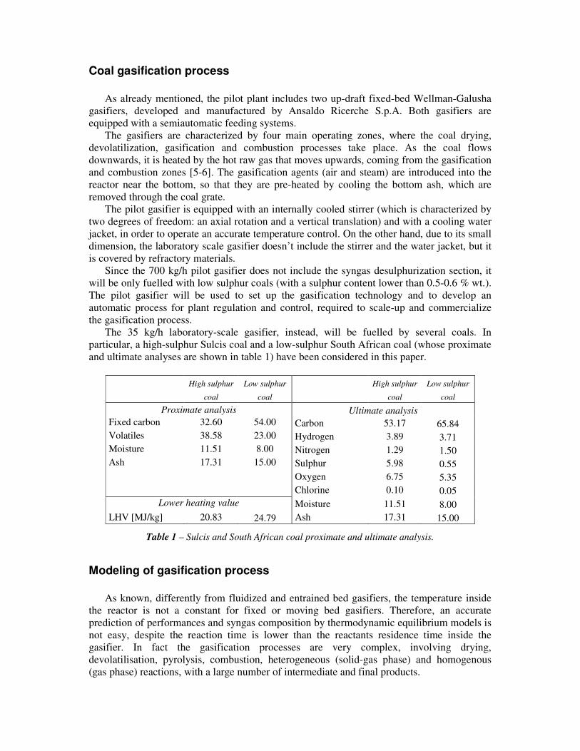
The 35 kg/h laboratory-scale gasifier, instead, will be fuelled by several coals. In particular, a high-sulphur Sulcis coal and a low-sulphur South African coal (whose proximate and ultimate analyses are shown in table 1) have been considered in this paper.
Table 1 – Sulcis and South African coal proximate and ultimate analysis.
Modeling of gasification process As known, differently from fluidized and entrained bed gasifiers, the temperature inside
the reactor is not a constant for fixed or moving bed gasifiers. Therefore, an accurate prediction of performances and syngas composition by thermodynamic equilibrium models is not easy, despite the reaction time is lower than the reactants residence time inside the gasifier. In fact the gasification processes are very complex, involving drying, devolatilisation, pyrolysis, combustion, heterogeneous (solid-gas phase) and homogenous (gas phase) reactions, with a large number of intermediate and final products.
Coal prehatingand drying
Coal devolatilization
Char gasificationand combustion
Steam andoxidant preheating
Coal
Coal
Syngas
Syngas
Syngas
Fixedcarbon TAR
Steam and oxidant
Steam and oxidantAsh
Ash
Char
SyngasSyngas
Steam
Volat.
Figure 2 – Simplified scheme of
the Aspen Plus-based model.
In order to evaluate the performances of the gasification section, three different equilibrium models have been developed. The preliminary analysis of gasification process has been carried out by using a modular code, developed by the Department of Mechanical Engineering of the University of Cagliari and implemented with Fortran language [7]. The main results of this analysis have been presented in previous papers [3-8].
The analysis shown in this paper is based on two different equilibrium models of the gasification process, developed by using Aspen Plus and ChemCAD commercial simulation software. Both these models evaluate the syngas composition and the gasification performances through the minimization of the Gibbs free energy.
Aspen Plus-based model
The first gasification model presented in this paper has been developed at the Department of Mechanical Engineering of the University of Cagliari and has been implemented by using the Aspen Plus software [9]. A detailed description of this model can be found in [10]. This model determines the raw syngas composition as well as the mass and energy balances of the overall gasification process and the main thermodynamic properties of each stream.
A simplified scheme of the gasifier model is shown in figure 2. The gasifier is schematised in several different zones: coal preparation, drying, devolatilisation, gasification and combustion, steam and oxidant preheating. In the preparation section, the coal is ground and pressurized by a nitrogen flow before being introduced inside the gasifier. At the top of the gasifier the coal is dried through a countercurrent heat exchange with the hot syngas leaving upward the gasification section. After being dried the coal is subjected to devolatilization processes and the steam and volatile gases released from the volatile matter are mixed with the syngas leaving upward the gasification section. In the gasification and combustion zone the char reacts with the gasification agents (steam and oxidant opportunely preheated) to form the syngas. At the bottom of the gasifier the ash cooling preheats steam and oxidant.
In the Aspen Plus based model, the medium temperature in the gasification zone is determined through an energy balance in the reactor and depends on both steam/coal and oxidant/coal ratios, “char” composition and temperature of main entering fluxes (“char”, steam and oxidant). Moreover, the syngas exit temperature is determined with respect to the countercurrent heat exchange process between the syngas and the coal inside the different section of the gasifier, calculated imposing a minimum temperature difference.
ChemCAD-based model
The second fixed-bed gasification model has been developed at the ENEA Research Centre of Casaccia near Rome. According to other countercurrent fixed-bed gasifier models developed in literature [5], the model is characterized by the presence of four main zones: a coal drying-devolatilization zone, a gasification zone, a combustion zone and finally an ash
cooling and steam-air preheating zone. The ChemCAD™ commercial process simulation software has been used for the model development and simulation [11].
In order to take into account the different mechanisms involved into the process, the whole gasifier has been modelled with several components, already present in the software catalogue of parts. Two separate reactors are used to simulate the equilibrium zones, different heat exchangers and phase separators have been considered. The coal, supplied at ambient conditions, enters on the top of the gasifier and is heated and dried by the hot raising syngas. Downstream, steam and volatile gas are sent upwards to join the syngas exit while char, ash and liquid tars are delivered down. The descending material is still heated, by the hot gas coming up from the gasification zone until liquid tars evaporate becoming gas. Downstream hot tar gas flow is sent upwards to join the syngas while the solid remainder is sent to the combustion reactor.
Here char and ash react with steam and oxidant, coming up from the preheating zone, producing ash (removed after cooling) and hot gas that raise up to the gasification zone together with the tar gases. The chemical equilibrium is calculated with the minimization of the Gibbs free energy. On the basis of the three main mass inputs data (coal, steam and air) is possible to calculate the operative temperatures of the different zones and the compositions and mass flows of the various streams. Other model inputs are the preheating temperature of coal, the minimum temperature difference between solids and gases and the discharge ash temperature. The model is able to valuate both adiabatic or water jacket gasifier behaviours taking in account the heat duty needed for the reactor cooling. Moreover is possible to vary the characteristic mass ratios (steam/coal and air/coal) to optimize the performance of the reactor in terms of gasification efficiency, hydrogen content in syngas and so on.
Results and discussion Some results of the computational analysis are reported below. In particular, are shown,
for both Sulcis and South African coal, the variation of syngas outlet temperature, lower heating value (LHV) and H2/CO molar ratio as a function of the air/coal mass ratio (�) and the steam/coal mass ratio (µ).
As a matter of fact the syngas outlet temperature is strictly related to the temperature in the gasification zone. The syngas temperature increases with the air/coal mass ratio (�), due to the greater availability of O2 that favours the combustion reactions in the gasification section and decreases with the steam/coal mass ratio (µ), but the reduction is limited especially with high value of �.
The syngas LHV decreases with both air/coal and steam/coal mass ratios, due to the strong dilution with air or steam. The variation from the lower to the higher values of � and µ ratios involves a sensible reduction of the syngas LHV, equal to about 40%.
1.2 1.4 1.6 1.8 2Air/coal mass ratio
200
300
400
500
600
Syng
as o
utle
t tem
pera
ture
[°C
]� = 0.25
� = 0.55
1.2 1.4 1.6 1.8 2Air/coal mass ratio
200
300
400
500
600
Syng
as o
utle
t tem
pera
ture
[°C
]� = 0.25
� = 0.55
1.2 1.4 1.6 1.8 2
Air/coal mass ratio
200
300
400
500
600
Syng
as o
utle
t tem
pera
ture
[°C
]
� = 0.25
� = 0.55
1.2 1.4 1.6 1.8 2Air/coal mass ratio
200
300
400
500
600
Syng
as o
utle
t tem
pera
ture
[°C
]
� = 0.25
� = 0.55
(a) Aspen-based model (b) ChemCAD-based model
Figure 4 –Syngas outlet temperature for gasification of Sulcis coal.
1.2 1.4 1.6 1.8 2Air/coal mass ratio
5
6
7
8
9
Syng
as L
HV
[M
J/kg
] � = 0.25
� = 0.55
1.2 1.4 1.6 1.8 2Air/coal mass ratio
5
6
7
8
9
Syng
as L
HV
[M
J/kg
] � = 0.25
� = 0.55
1.2 1.4 1.6 1.8 2
Air/coal mass ratio
5
6
7
8
9
Syng
as L
HV
[M
J/kg
] � = 0.25
� = 0.55
1.2 1.4 1.6 1.8 2Air/coal mass ratio
5
6
7
8
9
Syng
as L
HV
[M
J/kg
] � = 0.25
� = 0.55
(a) Aspen-based model (b) ChemCAD-based model
Figure 5 – LHV of produced syngas for gasification of Sulcis coal.
1.2 1.4 1.6 1.8 2Air/coal mass ratio
0.25
0.5
0.75
1
1.25
H2/C
O m
olar
ratio
� = 0.25
� = 0.55
1.2 1.4 1.6 1.8 2Air/coal mass ratio
0.25
0.5
0.75
1
1.25
H2/C
O m
olar
ratio
� = 0.25
� = 0.55
1.2 1.4 1.6 1.8 2
Air/coal mass ratio
0.25
0.5
0.75
1
1.25
H2/C
O m
olar
ratio
� = 0.25
� = 0.55
1.2 1.4 1.6 1.8 2Air/coal mass ratio
0.25
0.5
0.75
1
1.25
H2/C
O m
olar
ratio
� = 0.25
� = 0.55
(a) Aspen-based model (b) ChemCAD-based model
Figure 6 – H2/CO molar ratio of produced syngas for gasification of Sulcis coal.
2 2.2 2.4 2.6 2.8Air/coal mass ratio
300
400
500
600
700
800
Syng
as o
utle
t tem
pera
ture
[°C
]
� = 0.35
� = 0.65
2 2.2 2.4 2.6 2.8Air/coal mass ratio
300
400
500
600
700
800
Syng
as o
utle
t tem
pera
ture
[°C
]
� = 0.35
� = 0.65
2 2.2 2.4 2.6 2.8
Air/coal mass ratio
300
400
500
600
700
800
Syng
as o
utle
t tem
pera
ture
[°C
]
� = 0.35
� = 0.65
2 2.2 2.4 2.6 2.8Air/coal mass ratio
300
400
500
600
700
800
Syng
as o
utle
t tem
pera
ture
[°C
]
� = 0.35
� = 0.65
(a) Aspen-based model (b) ChemCAD-based model
Figure 7 – Temperature of produced syngas for gasification of South African coal.
2 2.2 2.4 2.6 2.8Air/coal mass ratio
4.5
5
5.5
6
6.5
7
7.5
Syng
as L
HV
[M
J/kg
] � = 0.35
� = 0.65
2 2.2 2.4 2.6 2.8Air/coal mass ratio
4.5
5
5.5
6
6.5
7
7.5
Syng
as L
HV
[M
J/kg
] � = 0.35
� = 0.65
� = 0.35
� = 0.65
2 2.2 2.4 2.6 2.8Air/coal mass ratio
4.5
5
5.5
6
6.5
7
7.5
Syng
as L
HV
[M
J/kg
] � = 0.35
� = 0.65
2 2.2 2.4 2.6 2.8Air/coal mass ratio
4.5
5
5.5
6
6.5
7
7.5
Syng
as L
HV
[M
J/kg
]
(a) Aspen-based model (b) ChemCAD-based model
Figure 8 – LHV of produced syngas for gasification of South African coal.
2 2.2 2.4 2.6 2.8Air/coal mass ratio
0.25
0.5
0.75
1
1.25
H2/C
O m
olar
ratio
� = 0.35
� = 0.65
2 2.2 2.4 2.6 2.8Air/coal mass ratio
0.25
0.5
0.75
1
1.25
H2/C
O m
olar
ratio
� = 0.35
� = 0.65
2 2.2 2.4 2.6 2.8
Air/coal mass ratio
0.25
0.5
0.75
1
1.25
H2/C
O m
olar
ratio
� = 0.35
� = 0.65
2 2.2 2.4 2.6 2.8Air/coal mass ratio
0.25
0.5
0.75
1
1.25
H2/C
O m
olar
ratio
� = 0.35
� = 0.65
(a) Aspen-based model (b) ChemCAD-based model
Figure 9 – H2/CO molar ratio of produced syngas for gasification of South African coal.
An increase of the steam/coal mass ratio µ supports the shift conversion reaction, reducing the CO molar fraction in the syngas, with the formation of H2 and CO2 and besides the lower gasification temperature hinders the CO formation respect to H2 and CO2. A greater air/coal mass ratio reduces the CO molar fraction, but the reduction is limited, because the higher temperature in the gasification section balances partly the effect of � and inhibits the shift conversion reactions facilitating the CO formation. Instead the syngas H2 molar fraction grows with the � ratio up to a maximum. Globally the CO/ H2 molar ratio shows a maximum, more marked for the high values of µ.
The trends of data for the high sulphur Sulcis coal, shown in figures 4-6, suggest a good agreement between the two different codes. The only significant difference is about the prediction of the syngas outlet temperature (figure 4). In particular, the Aspen code evaluates higher temperatures then ChemCAD (about 50 °C) in all the field of variation of the characteristic mass ratios; this is mainly due to the different approach in thermal balance calculation between the two models. On the other hand, syngas lower heating value and H2/CO molar ratio reveal a very good agreement.
The analysis for the low sulphur South African coal shows some additional differences. As shown in the figures 7-9, despite a temperature translation of about 50 °C, is confirmed the good agreement in syngas outlet temperature trend. Only for lower values of air/coal mass ratio (�) the estimates of lower heating value and H2/CO molar ratio are different, as a matter of facts, the ChemCAD code predicts lower values for LHV and higher H2/CO molar ratios with respect to Aspen Plus-based model. For medium-high values of � the simulation results are identical for both models.
Syngas treatment line As already mentioned, the Sotacarbo laboratory-scale gasification plant includes two
different syngas treatment lines: a cold gas desulphurization line and a hot gas hydrogen production line. The first is composed by a syngas desulphurization process which allows to use syngas in an internal combustion engine for power generation. The latter includes a hot gas desulphurization process, an integrated CO-shift and CO2 removal system and a hydrogen purification process.
Cold syngas desulphurization process
Depulverized syngas produced by the laboratory-scale gasifier is sent to the cold gas desulphurization section, in order to reduce the hydrogen sulphide concentration below the maximum values allowed by the CO-shift conversion processes (10-20 ppm). The lower amounts of the COS (carbonyl sulphide) are mainly removed by means of the raw gas wet scrubber.
The cold syngas desulphurization system here considered is based on a conventional chemical-physical H2S absorption process, operating at about 30-50 °C, carried out by a mixture of water, sodium hydroxide and sodium hypochlorite (is important to specify that the structure of the absorber will allow the execution of experimental tests using, as a solvent, methyldiethanolamine, which is highly selective for hydrogen sulphide [12], diluted in water). A preliminary analysis of this process has been carried out by using the ChemCAD simulation software, and can be found in a previous paper [13].
Hot syngas desulphurization process
In order to develop a small-scale commercial plant (where global efficiency plays an important role), a hot gas desulphurization process will also be tested in the Sotacarbo
High sulphur
coal
Low sulphur
coal
CO-shift operating conditions 1st stage temperature [°C] 400 2nd stage temperature [°C] 250 Pressure [bar] 1.01 Steam/CO molar ratio (design conditions) 2.5
Syngas feeding properties Mass flow [kg/h] 21.518 22.461 Temperature [°C] 350 350 Pressure [bar] 1.01 1.01
Syngas feeding composition CO 0.2762 0.2920 CO2 0.0226 0.0111 H2 0.1636 0.1861 N2 0.3829 0.3762 H2O 0.1238 0.1222 CH4 0.0264 0.0080 H2S traces traces COS traces traces Ar 0.0045 0.0044
Table 2 – CO-shift process: main operating conditions.
laboratory-scale gasification plant; in fact, even if these processes are still far from a massive industrial application, they are extremely simple in their plant configuration and management; moreover, hot syngas desulphurization processes allow to improve the efficiency of the integrated coal gasification plant due to the absence of a deep syngas cooling process.
In the Sotacarbo laboratory-scale plant, about 20% of the syngas produced by the gasification and depulverization sections is compressed (to 1.4 bar), heated to 350-500 °C and sent to the hot syngas desulphurization system [14]. The latter includes two identical reactors, operating in a hybrid series/parallel configuration.
Integrated water-gas shift and CO2 removal process
The syngas enrichment in hydrogen is carried out by using a two-stage catalytic CO-shift process, with an intermediate carbon dioxide absorption stage and a final CO2 removal process, as shown in figure 10. This integrated configuration has been selected to maximize the carbon monoxide conversion into CO2, for a future use of the hydrogen-rich fuel in a high efficiency power generation section (based on fuel cells).
The two CO2 removal stages are based on an innovative absorption system which is currently under development by Ansaldo Ricerche. In particular, the process carry out an absorption of carbon dioxide with a solution of water and monoethanolamine (MEA, HO-CH2-CH2-NH2) at an operating temperature of about 30 °C and at about atmospheric pressure [14]. The absorption process is highly influenced by absorption temperature and pressure and by pH value in the solvent solution (which depends on amine concentration).
In order to minimize the steam consumption and optimize heat exchanges in the integrated process, only a portion (about 50%) of syngas from the first CO-shift stage is sent to the intermediate CO2 absorption section.
The integrated process has been analyzed under the assumption of chemical equilibrium, with reference to the design conditions shown in table 2 and by using the Aspen Plus simulation software [9].
Obviously, by increasing the steam/CO molar ratio at the inlet of the hydrogen production system, the chemical equilibrium of the water-gas shift reaction shifts towards the
clean syngas
CO-shift(1st stage)
CO-shift(2nd stage)
hydrogen rich syngas
CO2 removal(intermediate stage)
CO2 removal(final stage)
clean syngas
CO-shift(1st stage)
CO-shift(2nd stage)
hydrogen rich syngas
CO2 removal(intermediate stage)
CO2 removal(final stage)
Figure 10 – Simplified scheme of the integrated CO-
shift and CO2 removal process.
1 1.5 2 2.5 3 3.5
Steam/CO molar ratio
0.2
0.4
0.6
0.8
1
Con
vers
ion
rate
1st stage
2nd stage
Overall process
Low Sulphur Coal
High Sulphur Coal
Figure 11 – Equilibrium conversion in the two-
stage water-gas shift process [C].
High sulphur
Low sulphur
Expected syngas properties Mass flow [kg/h] 12.561 13.029 Temperature [°C] 30 30 Pressure [bar] 1.01 1.01
Expected syngas composition CO 0.0140 0.0140 CO2 0.0015 0.0015 H2 0.4809 0.5158 N2 0.4308 0.4169 H2O 0.0381 0.0380 CH4 0.0297 0.0089 H2S traces traces COS traces traces Ar 0.0051 0.0049
0 0.2 0.4 0.6 0.8 1
Oxygen purity (%vol)
0
0.2
0.4
0.6
0.8
1
Fina
l con
cent
ratio
n
H2
N2
Low Sulphur Coal
High Sulphur Coal
Table 3 – Syngas from the final CO2 absorption
stage. Figure 12 – Hydrogen and nitrogen concentration in treated syngas.
reaction products. In particular, figure 11 shows the trend of carbon monoxide conversion (in each of the two single stages and in the overall CO-shift process) by varying this molar ratio.
The equilibrium CO conversion is very similar for both coals due to the similar composition of the two syngas (figure 11). Moreover, according to the design conditions, the assumption of a steam/CO molar ratio equal to 2.5 represents a good compromise between conversion efficiency and reactor size.
Hydrogen separation system
In order to assess the capabilities of the pilot plant to produce a hydrogen-rich fuel for fuelling advanced power generation systems (as micro gas turbines and fuel cells), the Sotacarbo pilot plant will be equipped with an hydrogen purification system. In particular, a PSA (Pressure Swing Adsorption) system will be selected for the current plant configuration, but other kind of processes will be considered for the plant scale-up.
The design of the hydrogen separation system strongly depends on the oxidant used in the gasification process. In fact, syngas from the integrated water-gas shift conversion and CO2 removal process is mainly composed by hydrogen and nitrogen. In particular, table 3 shows the expected syngas composition at the design conditions (by using air as gasification agent) for the two coals here considered.
If the gasification air is enriched with oxygen, the hydrogen concentration in the treated syngas increases from 48% to about 86% for the high sulphur coal and from 54% to 94% for the low sulphur coal, as shown in figure 12. Therefore, the design of the commercial-scale integrated plant, will depend on the optimum trade-off between the effects of air enrichment
with oxygen and the efficiency of hydrogen separation system.
Conclusions The increasing interest in hydrogen production from low rank fuels through gasification
processes has led Sotacarbo, Ansaldo Ricerche, ENEA and the Department of Mechanical Engineering of the University of Cagliari to develop an integrated gasification process for the co-production of hydrogen and electrical energy for medium and small-scale commercial applications. In this framework, a research project (called CO.HY.GEN, Coal to Hydrogen Generation), concerning the development of a gasification and syngas treatment pilot plant, has been funded by the Italian Ministry of Instruction, University and Research (MIUR). The pilot plant has been recently constructed in the new Sotacarbo Research Centre at Carbonia, near Cagliari.
In particular, the pilot plant, which is composed by two gasification sections (a pilot 700 kg/h gasifier and a laboratory-scale 35 kg/h gasifier) and by a syngas treatment line, will carry out a number of experimental tests in order to choose the most suitable technologies, as well as to optimize each section and the overall plant integration.
As to the gasification section, this paper compares the results of a simulation analysis carried out by using two different gasification models, implemented with Aspen Plus and ChemCAD software. In particular, the effects of the main gasification operating parameters (in particular the air/coal and steam/coal mass ratios) on syngas properties have been analyzed, with reference to two different coals. The comparison between the results obtained with the two gasification models suggests a good agreement between the two different codes, in particular for the lower heating value and the composition of the produced syngas. As for the syngas outlet temperature, a small difference (about 50 °C) results by the different approach in the thermal balance calculation.
As to the water-gas shift conversion process, the most significant parameter is the steam/CO molar ratio. In particular, the study demonstrates that a steam/CO molar ratio equal to 2.5 is enough to achieve an almost complete CO conversion.
Finally, the analysis shows that, if the gasification air is enriched with oxygen, the hydrogen concentration in the treated syngas increases from about 50% to 85-90%. This effect strongly influences the design of the hydrogen separation system and requires a careful optimization of the integrated commercial-scale plant.
References
[1] U.S. Department of Energy, Annual Energy Outlook 2004, available at www.eia.doe.gov/oiaf/aeo/, January 2004.
[2] S. Wadhwani, A.K. Wadhwani, R.B. Agarwal, Clean coal technologies – recent advances, proc. First International Conference on Clean Coal Technologies for Our Future, Chia Laguna, Sardinia, Italy, 21-23 October 2002.
[3] A. Pettinau, C. Amorino, A. Orsini, D. Cocco, Sotacarbo R&D project for hydrogen production from coal and CO2 removal, proc. 22nd Annual International Pittsburgh Coal Conference, Pittsburgh, Pennsylvania, September 12-15, 2005.
[4] C. Amorino, G. Calì, M. Fadda, E. Maggio, A. Pettinau, Sotacarbo coal-to-hydrogen pilot plant, project development and plant analysis, proc. Third International Conference on Clean Coal Technologies for Our Future, Cagliari, Italy, 15-17 May 2007.
[6] O.H. Hahn, D.P. Wesley, B.A. Swisshelm, S. Maples, J. Withrow, A mass and energy balance of a Wellman-Galusha gasifier, Fuel Processing Technology, 2 (1979), p. 1-6.
[7] G. Cau, D. Cocco, T. Pilloni, Equilibrium model for predicting performances of coal and low-grade fuel gasification systems, proc. Energy and Environment Towards the Year 2000 International Conference, Capri, Italy, June 3-5, 1993.
[8] G. Cau, D. Cocco, V. Tola, Computer simulation and performance evaluation of fixed-bed coal gasification process, proc. Second International Conference on Clean Coal Technologies for Our Future, Castiadas, Sardinia, Italy, 10-12 May 2005.
[9] Aspen Technology, Inc., Aspen Plus Reference Guide, 1996. [10] V. Tola, G. Cau, Process analysis and performance evaluation of updraft coal gasifiers,
proc. Third International Conference on Clean Coal Technologies for Our Future, Cagliari, Italy, 15-17 May 2007.
[11] Chemstation, Inc., ChemCAD, User Guide and Tutorial, Houston, Texas, USA, 2002. [12] M.A. Pacheco, G.T. Rochelle, Rate-based modeling of reactive absorption of CO2 and
H2S into aqueous methyldiethanolamine, Industrial Engineering Chemical Research, vol. 37, 1998, p. 4107-4117.
[13] G. Raggio, A. Pettinau, A. Orsini, M. Fadda, D. Cocco, P. Deiana, M.L. Pelizza, M. Marenco, Coal gasification pilot plant for hydrogen production. Part A: coal gasification and syngas desulphurization, proc. Second International Conference on Clean Coal Technologies for Our Future, Castiadas, Sardinia, Italy, 10-12 May 2005.
[14] G. Raggio, A. Pettinau, A. Orsini, M. Fadda, D. Cocco, P. Deiana, M.L. Pelizza, M. Marenco, Coal gasification pilot plant for hydrogen production. Part B: syngas conversion and hydrogen separation, proc. Second International Conference on Clean Coal Technologies for Our Future, Castiadas, Sardinia, Italy, 10-12 May 2005.