20

1
Contents
Water Boiler Controls 2-7
Universal Temperature Limit, Boiler Reset and Low Water ................................ 2Cut-Off – Residential [HydroStat Model 3200 and 3250]
HydroStat Accessories and Electro-Wells™ ............................................................ 3
HydroStat-IC Five Function Gas Boiler Control .................................................... 4
Universal Temperature Limit and Low Water Cut-Off – Residential .................... 5[HydroStat Model 3150]
Universal High Temperature Limit, Boiler Reset and Low .................................. 5Water Cut-Off – Residential [HydroStat Model 3000]
Low Water Cut-Offs – Residential/Commercial ...................................................... 6[1100 Series]
Low Water Cut-Offs – Residential/Commercial ...................................................... 7[24 and 170 Series, 500 Series, 600 Series, 700 Series]
Steam Boiler Controls 8-14
Low Water Cut-Offs – Residential/Commercial ...................................................... 8,9[400 Series, 711 and 724 Series, CG400 Series]
Pump Controller/ LWCO – Commercial/Industrial .................................................. 10[250 Series, Model 270SV]
Secondary Low Water Cut-Offs – Commercial/Industrial ...................................... 11[500 and 700 Series]
Flow Switches – Residential/Commercial/Industrial .............................................. 12[Model FS200 and FS204]
Water Feeder – Residential ...................................................................................... 13[Model VXT-24, VXT-120]
Water Feeder – Commercial/Industrial .................................................................... 14[Model VXTC, WM-1 Water Meter]
Other Controls 15
Multi-Purpose Liquid Level Control – Commercial/Industrial .............................. 15[Model 727 and 787]
AcuTemp Temperature Control ................................................................................ 15
Reference 16
Probe Options/Specifications .................................................................................. 16
Manifold Fittings........................................................................................................ 16
CROSS REFERENCE GUIDE is located inside back cover
RESIDENTIAL COMMERCIAL INDUSTRIAL
Hydrolevel Catalog 2018 Page 1
• Universal Aquastat† Replacement • Easy Dial Type Set-Up• Dynamic Temperature Display• Test/Settings Button• Low Water Cut-Off
• Fuel Saving Boiler Reset • Thermal Targeting – Simply dial in the number of heatingzones. The on-board microprocessor will save fuel by adjust-ing boiler temperature based on heating demand.
• Outdoor Reset Ready – Provides outdoor reset and warmweather shutdown functionality with the addition ofHydrolevel’s low cost OS-100 Outdoor Sensor Kit.
2
WAT E R B O I L E R C O N T R O L S
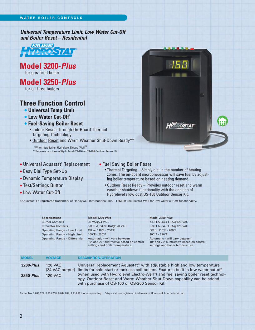
Universal Temperature Limit, Low Water Cut-Off and Boiler Reset – Residential
Model 3200-Plusfor gas-fired boiler
Model 3250-Plusfor oil-fired boilers
Three Function Control• Universal Temp Limit• Low Water Cut-Off*
• Fuel-Saving Boiler Reset• Indoor Reset Through On-Board Thermal Targeting Technology
• Outdoor Reset and Warm Weather Shut-Down Ready***When installed on Hydrolevel Electro-Well™
**Requires purchase of Hydrolevel OS-100 or OS-200 Outdoor Sensor Kit
MODEL VOLTAGE DESCRIPTION/OPERATION
3200-Plus 120 VAC(24 VAC output)
3250-Plus 120 VAC
Specifications Model 3200-Plus Model 3250-PlusBurner Contacts 30 VA@24 VAC 7.4 FLA, 44.4 LRA@120 VACCirculator Contacts 5.8 FLA, 34.8 LRA@120 VAC 5.8 FLA, 34.8 LRA@120 VACOperating Range – Low Limit Off or 110°F - 200°F Off or 110°F - 200°FOperating Range – High Limit 100°F - 220°F 100°F - 220°FOperating Range – Differential Automatic – will vary between Automatic – will vary between
10° and 20° subtractive based on control 10° and 20° subtractive based on controlsettings and boiler temperature settings and boiler temperature
Universal replacement Aquastat* with adjustable high and low temperaturelimits for cold start or tankless coil boilers. Features built in low water cut-off(when used with Hydrolevel Electro-Well™) and fuel saving boiler reset technol-ogy. Outdoor Reset and Warm Weather Shut-Down capability can be addedwith purchase of OS-100 or OS-200 Sensor Kit.
Patent No. 7,891,572; 8,931,708; 8,844,834; 9,416,981; others pending *Aquastat is a registered trademark of Honeywell International, Inc.
†Aquastat is a registered trademark of Honeywell International, Inc. ††Must use Electro-Well for low water cut-off functionality.
Hydrolevel Catalog 2018 Page 2
3
WAT E R B O I L E R C O N T R O L S
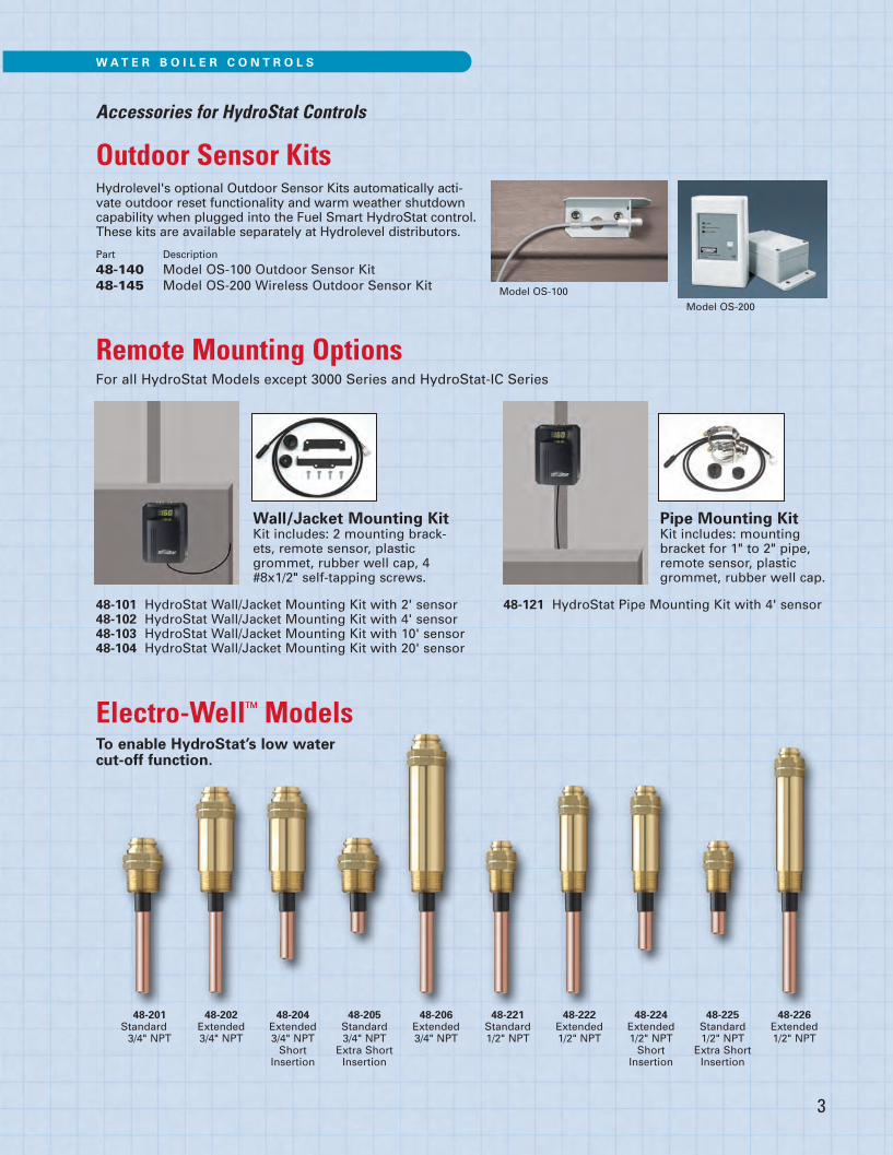
Accessories for HydroStat Controls
Outdoor Sensor Kits
48-201Standard3/4" NPT
48-202Extended3/4" NPT
48-204Extended3/4" NPTShort
Insertion
48-205Standard3/4" NPTExtra Short Insertion
48-206Extended3/4" NPT
48-221Standard1/2" NPT
48-222Extended1/2" NPT
48-224Extended1/2" NPTShort
Insertion
48-225Standard1/2" NPTExtra ShortInsertion
48-226Extended1/2" NPT
Electro-Well™ ModelsTo enable HydroStat’s low water cut-off function.
Remote Mounting OptionsFor all HydroStat Models except 3000 Series and HydroStat-IC Series
Wall/Jacket Mounting KitKit includes: 2 mounting brack-ets, remote sensor, plasticgrommet, rubber well cap, 4#8x1/2" self-tapping screws.
48-101 HydroStat Wall/Jacket Mounting Kit with 2' sensor48-102 HydroStat Wall/Jacket Mounting Kit with 4' sensor48-103 HydroStat Wall/Jacket Mounting Kit with 10' sensor48-104 HydroStat Wall/Jacket Mounting Kit with 20' sensor
48-121 HydroStat Pipe Mounting Kit with 4' sensor
Pipe Mounting KitKit includes: mounting bracket for 1" to 2" pipe,remote sensor, plastic grommet, rubber well cap.
Hydrolevel's optional Outdoor Sensor Kits automatically acti-vate outdoor reset functionality and warm weather shutdowncapability when plugged into the Fuel Smart HydroStat control.These kits are available separately at Hydrolevel distributors.
Part Description
48-140 Model OS-100 Outdoor Sensor Kit48-145 Model OS-200 Wireless Outdoor Sensor Kit Model OS-100
Model OS-200
Hydrolevel Catalog 2018 Page 3

G A S B O I L E R C O N T R O L S
4
For atmospheric and induced draft boilers
Specifications HydroStat-ICLine voltage input 120 VAC, 50/60 HZLow voltage input 24 VAC, 40 VAInducer (4200i) 6 FLA, 18 LRA @ 120 VACVent damper (4200a) 0.5 A @ 24 VACCirculator contacts 5.8 FLA, 34.8 LRA @ 120 VACOperating range - low limit Off or 110°F (43°C) - 200°F (93°C)Operating range - high limit 100°F (38°C) - 220°F (104°C)
Five Function Control• Ignition – Direct Spark Ignition withsingle rod flame sensing
• Temperature Limit Control –Designed for cold start and tanklesscoil boilers
• Low Water Cut-Off – Provides pro-tection against potentially dangerouslow water conditions when installedwith the Hydrolevel Electro-Well
• Fuel Saving Boiler Reset – Achievedby Thermal Targeting or optionalOutdoor Reset capabilities
• Two Zone – Circulator outputs forDHW or second heating zone
Low TemperatureLimit Setting
(OFF or 110°-220°F)Factory: OFF
High TemperatureLimit Setting (100°-220°F)Factory: 190°F
Spade Connectorsfor OS-100 OutdoorSensor Kit
Diagnostic LEDs
�
�
Economy Dial(OFF or LO, 1, 2, 3,4, 5, HI)Factory: 1
Indicator Light(indicates heat call)
Jumper�
Test/Settings Button
�
Dynamic Display
Water Temperatureand Real Time
Verification of SettingAdjustments.
Vent DamperReceptacle*
Draft InducerReceptacle*
Differentials are automaticand will vary based on control settings and boilertemperature.
Note: The high limit differentialcan be adjusted when the econ-omy feature is turned off.
*Model specific
MODEL VOLTAGE DESCRIPTION/OPERATION
4200A 24 VAC4200i 24 VAC
Multi-function control for gas boilers (4200A -Atmospheric / 4200i - Forced Draft).Provides direct spark ignition, temperature limit control, low water-cut off, fuelsaving boiler reset and circular outputs for DHW or second heating zone.
Hydrolevel Catalog 2018 Page 4
WAT E R B O I L E R C O N T R O L S
5
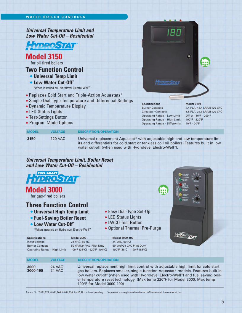
Universal Temperature Limit and Low Water Cut-Off – Residential
Model 3150for oil-fired boilers
Two Function Control• Universal Temp Limit• Low Water Cut-Off*
*When installed on Hydrolevel Electro-Well™
Patent No. 7,891,572; 8,931,708; 8,844,834; 9,416,981; others pending *Aquastat is a registered trademark of Honeywell International, Inc.
MODEL VOLTAGE DESCRIPTION/OPERATION
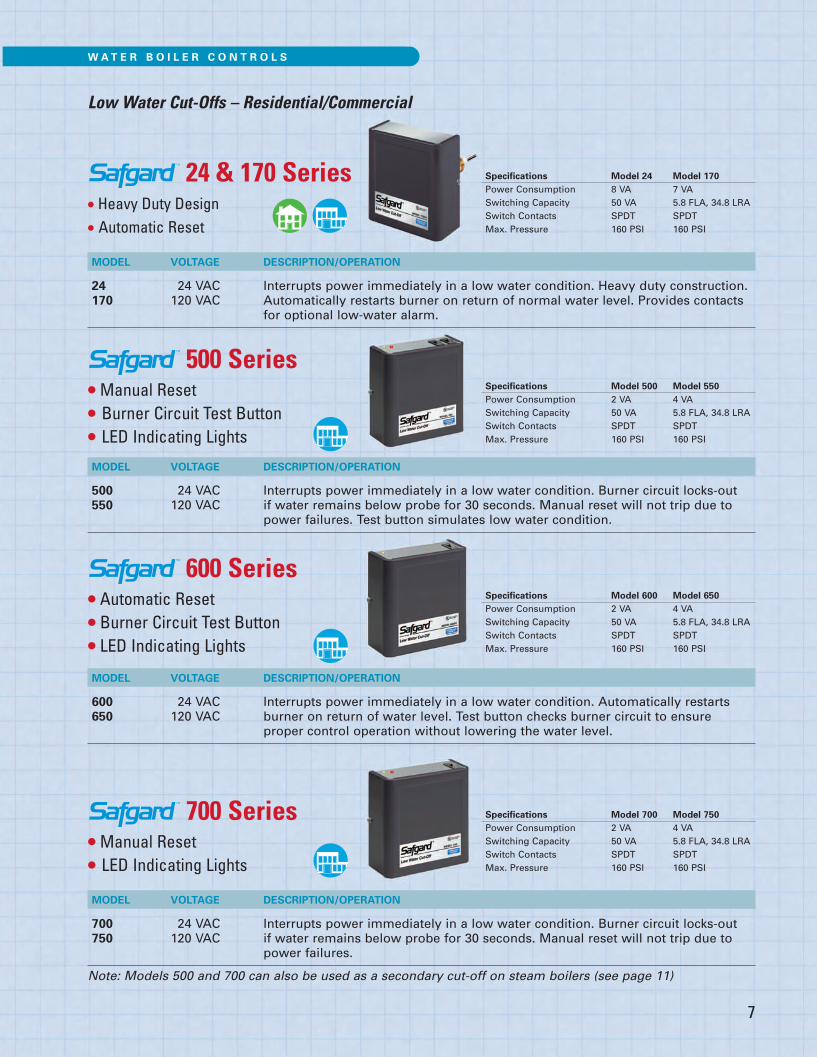
3000 24 VAC3000-190 24 VAC
Three Function Control• Universal High Temp Limit• Fuel-Saving Boiler Reset• Low Water Cut-Off*
*When installed on Hydrolevel Electro-Well™
Specifications Model 3000 Model 3000-190Input Voltage 24 VAC, 60 HZ 24 VAC, 60 HZBurner Contacts 50 VA@24 VAC Pilot Duty 50 VA@24 VAC Pilot DutyOperating Range – High Limit 100°F (38°C) - 220°F (104°C) 100°F (38°C) - 190°F (88°C)
Universal replacement high limit control with adjustable high limit for cold startgas boilers. Replaces smaller, single-function Aquastat* models. Features built inlow water cut-off (when used with Hydrolevel Electro-Well™) and fuel saving boil-er temperature reset technology. (Max temp 220°F for Model 3000. Max temp190°F for Model 3000-190)
Universal Temperature Limit, Boiler Reset and Low Water Cut-Off – Residential
Model 3000for gas-fired boilers
• Easy Dial-Type Set-Up• LED Status Lights• LWCO Test Button• Optional Thermal Pre-Purge
MODEL VOLTAGE DESCRIPTION/OPERATION
3150 120 VAC Universal replacement Aquastat* with adjustable high and low temperature lim-its and differentials for cold start or tankless coil oil boilers. Features built in low water cut-off (when used with Hydrolevel Electro-Well™).
Specifications Model 3150Burner Contacts 7.4 FLA, 44.4 LRA@120 VACCirculator Contacts 5.8 FLA, 34.8 LRA@120 VACOperating Range – Low Limit Off or 110°F - 200°FOperating Range – High Limit 100°F - 220°FOperating Range – Differential 10°F - 30°F
• Replaces Cold Start and Triple-Action Aquastats*• Simple Dial-Type Temperature and Differential Settings• Dynamic Temperature Display• LED Status Lights• Test/Settings Button• Program Mode Options
Hydrolevel Catalog 2018 Page 5

1100 Series• Compact Design
• Automatic and Manual Reset Models
• Burner Circuit Test Button• Power and Low Water LED Indicators
Low Water Cut-Offs – Residential/Commercial
MODEL RESET VOLTAGE DESCRIPTION/OPERATION
1100 Automatic 24 VAC Interrupts power immediately in a low water condition. Automatically1150 Automatic 120 VAC (manually for 1100M) restarts burner on return of water level. 1100M Manual 24 VAC Features test button, onboard indicating lights and easy to follow
installation instructions. Model 1100 includes plug-in wire harnesswith labeled quick-connect terminals.
Safgard 1100 Series Wire Harness OptionsModel 1100 is available with additional wiring harnesses for popular boilers
45-531-54 Standard wire harness for Model 1100 LWCO 16.00 10.88
45-347 Wire harness for connecting Model 1100 to Burnham PVGA, PVCGA, Series 2,New Yorker CG-D
45-348 45-348 Wire harness for connecting Model 1100 to UTC Boiler Control Module
45-349 45-349 Wire harness for connecting Model 1100 to Lochinvar Knight and Solution, Weil-McLain Ultra
45-350 45-350 Wire harness for connecting Model 1100 to Burnham CHG, SCG, PVG, Crown Bimini
45-353 45-353 Wire harness for connecting Models 1100 and 1100M to vent damper plug on boilercontrol modules
Specifications Model 1100 Model 1100M Model 1150 Power Consumption 1 VA 1 VA 4 VASwitching Capacity 50 - VA 50 VA 125 VASwitch Contacts SPST SPST SPSTMax. Pressure 160 PSI 160 PSI 160 PSIMax. Water Temperature 250° F 250° F 250° F
WAT E R B O I L E R C O N T R O L S
6
Hydrolevel Catalog 2018 Page 6
MODEL VOLTAGE DESCRIPTION/OPERATION
24 24 VAC Interrupts power immediately in a low water condition. Heavy duty construction.170 120 VAC Automatically restarts burner on return of normal water level. Provides contacts
for optional low-water alarm.
7
WAT E R B O I L E R C O N T R O L S
Low Water Cut-Offs – Residential/Commercial
24 & 170 Series• Heavy Duty Design• Automatic Reset
500 Series• Manual Reset• Burner Circuit Test Button• LED Indicating Lights
600 Series• Automatic Reset• Burner Circuit Test Button• LED Indicating Lights
700 Series• Manual Reset• LED Indicating Lights
Specifications Model 500 Model 550 Power Consumption 2 VA 4 VASwitching Capacity 50 VA 5.8 FLA, 34.8 LRASwitch Contacts SPDT SPDTMax. Pressure 160 PSI 160 PSI
MODEL VOLTAGE DESCRIPTION/OPERATION
500 24 VAC Interrupts power immediately in a low water condition. Burner circuit locks-out550 120 VAC if water remains below probe for 30 seconds. Manual reset will not trip due to
power failures. Test button simulates low water condition.
MODEL VOLTAGE DESCRIPTION/OPERATION
700 24 VAC Interrupts power immediately in a low water condition. Burner circuit locks-out750 120 VAC if water remains below probe for 30 seconds. Manual reset will not trip due to
power failures.
MODEL VOLTAGE DESCRIPTION/OPERATION
600 24 VAC Interrupts power immediately in a low water condition. Automatically restarts 650 120 VAC burner on return of water level. Test button checks burner circuit to ensure
proper control operation without lowering the water level.
Specifications Model 24 Model 170 Power Consumption 8 VA 7 VASwitching Capacity 50 VA 5.8 FLA, 34.8 LRASwitch Contacts SPDT SPDTMax. Pressure 160 PSI 160 PSI
Specifications Model 600 Model 650 Power Consumption 2 VA 4 VASwitching Capacity 50 VA 5.8 FLA, 34.8 LRASwitch Contacts SPDT SPDTMax. Pressure 160 PSI 160 PSI
Specifications Model 700 Model 750 Power Consumption 2 VA 4 VASwitching Capacity 50 VA 5.8 FLA, 34.8 LRASwitch Contacts SPDT SPDTMax. Pressure 160 PSI 160 PSI
Note: Models 500 and 700 can also be used as a secondary cut-off on steam boilers (see page 11)
Hydrolevel Catalog 2018 Page 7

S T E A M B O I L E R C O N T R O L S
Low Water Cut-Offs – Residential/Commercial
711 and 724 Series• Low Water Cut-Off for Sight-Glass Attachment
• Two Probe Design
• Automatic Reset
• Includes Quick Hook-Up Fittings for 8" to 14" Sight Glasses
MODEL VOLTAGE DESCRIPTION/OPERATION
724CF 24 VAC Mounts to sight glass tappings. Maintains water level between two probes.711CF 120 VAC Includes 711C manifold, two model EL1214 probes and quick hook-up fittings.
Note: The 711 & 724 Series is recommended for use on older boilers that do nothave tappings suitable for Safgard 400 and CycleGard 400 Series cut-offs.
724WF 24 VAC Same as CF models (described above), includes water feed valve assembly.711WF 120 VAC
Specifications 711 Series 724 SeriesPower Consumption 8 VA 7 VASwitching Capacity 50 VA 5.8 FLA, 34.8 LRASwitch Contacts SPDT SPDTMax. Steam Pressure 35 PSI 35 PSI
8
400 Series• 15 Second Burner Off Delay• 30 Second Burner On Delay• Low Water Indicating Light
MODEL VOLTAGE DESCRIPTION/OPERATION
400 24 VAC Burner circuit contacts open after 15 second delay in a low water condition. 450 120 VAC Delay prevents short cycling caused by momentary fluctuations in the boiler
water level. Automatically reactivates burner circuit 30 seconds after waterreaches the probe, allowing optional water feeder to raise water level above the probe. See page 13 for information on VXT Water Feeder.
Specifications Model 400 Model 450 Power Consumption 2 VA 4 VASwitching Capacity 50 VA 5.8 FLA, 34.8 LRASwitch Contacts SPDT SPDTMax. Steam Pressure 15 PSI 15 PSI
Hydrolevel Catalog 2018 Page 8

Low Water Cut-Offs – Residential/Commercial
CG400 Series• Intermittent Level Test – Maximum Protection forFoaming Boilers
• 15 Second Burner Off Delay• 30 Second Burner On Delay• Automatic Reset
• Low Water Indicating Light
• Direct Boiler Mounting – Eliminates Blowdowns
MODEL VOLTAGE DESCRIPTION/OPERATION
CG400-2090 24 VAC Burner circuit contacts open after 15 second delay in a low water condition.CG450-1560 120 VAC Delay prevents short cycling caused by momentary fluctuations in the boiler CG450-2060 120 VAC water level. Automatically reactivates burner circuit 30 seconds after water
reaches the probe, allowing optional water feeder to raise water level above the probe. Intermittent Level Test (ILT) feature provides maximum boiler protection by removing power from the burner circuit at set intervals. � Models ending in “1560” perform the ILT every 15 minutes for 60 seconds.� Models ending in “2060” perform the ILT every 20 minutes for 60 seconds.� Models ending in “2090” perform the ILT every 20 minutes for 90 seconds.
CGT450-2060 120 VAC Same as CG450-2060 (described above) with added feature for boilers equippedwith tankless coils. The CGT450-2060 suspends operation of the IntermittentLevel Test when the boiler is receiving a call for domestic hot water. This featureensures continued burner operation during a demand for hot water.
U.S. Patent No. 5,739,504; 6,390,027
Specifications Model CG400 Models CG450 and CGT450
Power Consumption 2.1 VA 4.2 VASwitching Capacity 50 VA 5.8 FLA, 34.8 LRASwitch Contacts SPDT SPDTMax. Steam Pressure 15 PSI 15 PSI
Maximum boiler protection – Even in SURGING and FOAMING boilers.CycleGard continually monitors the boiler water level likeother probe type cut-offs. But, unlike any other cut-off,CycleGard uses Intermittent Level Test (ILT) technology toprovide protection against false signals created by foamingand volatile water conditions in the boiler. CycleGard’s ILTperiodically removes power from the burner circuit. Duringthis test, foam dissipates and the water level stabilizes –allowing CycleGard to monitor the true water level in theboiler. Since 1996, the superior protection of CycleGard hasmade it the standard low water cut-off for many of theindustry’s leading boiler manufacturers.
See CycleGard video at www.hydrolevel.com
9
S T E A M B O I L E R C O N T R O L S
Hydrolevel Catalog 2018 Page 9
S T E A M B O I L E R C O N T R O L S
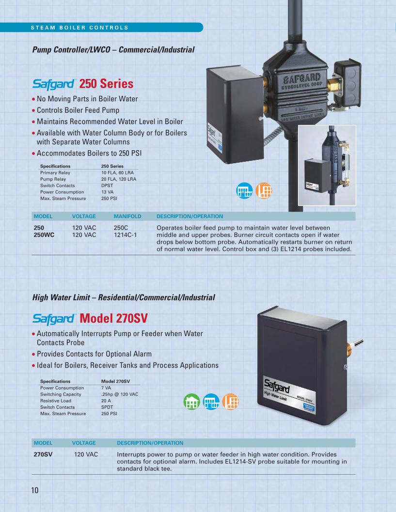
250 Series• No Moving Parts in Boiler Water
• Controls Boiler Feed Pump
• Maintains Recommended Water Level in Boiler
• Available with Water Column Body or for Boilerswith Separate Water Columns
• Accommodates Boilers to 250 PSI
Model 270SV• Automatically Interrupts Pump or Feeder when WaterContacts Probe
• Provides Contacts for Optional Alarm• Ideal for Boilers, Receiver Tanks and Process Applications
Specifications 250 SeriesPrimary Relay 10 FLA, 60 LRAPump Relay 20 FLA, 120 LRASwitch Contacts DPSTPower Consumption 13 VAMax. Steam Pressure 250 PSI
Specifications Model 270SVPower Consumption 7 VASwitching Capacity .25hp @ 120 VACResistive Load 20 ASwitch Contacts SPDTMax. Steam Pressure 250 PSI
MODEL VOLTAGE MANIFOLD DESCRIPTION/OPERATION
250 120 VAC 250C Operates boiler feed pump to maintain water level between250WC 120 VAC 1214C-1 middle and upper probes. Burner circuit contacts open if water
drops below bottom probe. Automatically restarts burner on returnof normal water level. Control box and (3) EL1214 probes included.
Pump Controller/LWCO – Commercial/Industrial
High Water Limit – Residential/Commercial/Industrial
MODEL VOLTAGE DESCRIPTION/OPERATION
270SV 120 VAC Interrupts power to pump or water feeder in high water condition. Provides contacts for optional alarm. Includes EL1214-SV probe suitable for mounting instandard black tee.
10
Hydrolevel Catalog 2018 Page 10

Secondary Low Water Cut-Offs – Commercial/Industrial
500 and 700 Series• Manual Reset with 30 Second Delay and Power Outage Protection
• Burner Circuit Test Button (500 Series only)• LED Indicating Lights• Meets ASME CSD-1 Requirements for SecondaryCut-Offs on Commercial Steam Boilers
Specifications Models 500 Models 550and 700 and 750
Power Consumption 2 VA 4 VASwitching Capacity 50 VA 5.8 FLA, 34.8 LRASwitch Contacts SPDT SPDTMax. Steam Pressure 250 PSI 250 PSI
MODEL VOLTAGE DESCRIPTION/OPERATION
500 24 VAC Interrupts power in a low water condition. Burner circuit locks-out if water 550 120 VAC remains below probe for 30 seconds. Manual reset will not trip due to power
failures. Test button checks burner circuit to ensure proper control operation andlock-out function without lowering the water level. Note: Can also be used as aprimary cut-off on hot water boilers (see page 7).
700 24 VAC Same as 500 Series above without test button feature.750 120 VAC
Typical Steam Boiler Installations
�
�
��
� Model 250 or 250WC� Model 270SV High Water Limit� Model 550 or 750 Secondary LWCO� Model 727 Tank Pump Control
11
S T E A M B O I L E R C O N T R O L S
Hydrolevel Catalog 2018 Page 11

12
L I Q U I D F L O W S W I T C H
Model FS200 and FS204
• EPDM Seal for Superior Performance over Mechanical Bellows
• Universal Design – Replaces Flow Switches byMcDonnell Miller, Penn, Taco, Potter, Watts and others
• Single Pole Double Throw Switch for Operating Signal Devices, Motors, Alarms, Metering Devices and Heating Units
• Includes Four Heavy Duty Stainless Steel Paddles
• Two 7/8" Electrical Knock-Outs for 1/2" Conduit
• For Use on 1" to 6" Diameter Pipe
• 1" NPT Pipe Connection
MODEL DESCRIPTION
FS200 Activates or deactivates electrical equipment upon the start or stop of liquid flow. NEMA 1.
FS204 Activates or deactivates electrical equipment upon the start or stop of liquid flow. NEMA 4.
FLOW SPECIFICATIONS IN GPMPipe Size � 1" 11⁄4" 11⁄2" 2" 21⁄2" 3" 4" 5" 6"
MinimumAdjustment
Flow Activates 4.5 8.1 11.8 16.5 25 33 51 85 120
Flow Deactivates 2.2 6.8 7.6 9.3 19 22 38 75 100
MaximumAdjustment
Flow Activates 14.8 22.1 25.7 32.3 75 90 110 170 240
Flow Deactivates 13.8 20.1 23.7 30.5 72 85 100 155 220
Specifications Model FS200 Model FS204Enclosure NEMA 1 – General Purpose NEMA 4 – Wet LocationsControl Chassis Material 13 gauge galvanized steel Anodized cast aluminumControl Cover Material 16 gauge powder coated steel Powder coated cast aluminumMaximum Fluid Temperature 250°F (121°C) 250°F (121°C)Minimum Fluid Temperature 32°F (0°C) 32°F (0°C)Contacts SPDT switch 7.4 FLA, 44.4 LRA SPDT switch 7.4 FLA, 44.4 LRA
@120VAC Motor Duty @120VAC Motor DutyPilot Duty Rating 125VA@120/240VAC 125VA@120/240VACMaximum Service Pressure 160 psi 160 psiUsage 1" to 6" pipe sizes (see Flow Chart) 1" to 6" pipe sizes (see Flow Chart)
MODEL FS200
MODEL FS204
For Accurate Monitoring of Liquid Flow in Pipelines
Hydrolevel Catalog 2018 Page 12
S T E A M B O I L E R C O N T R O L S
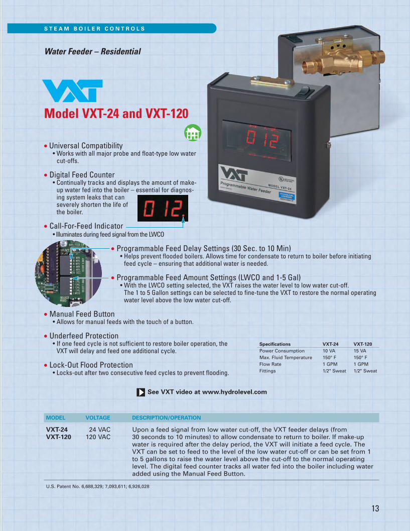
Water Feeder – Residential
Model VXT-24 and VXT-120
• Universal Compatibility • Works with all major probe and float-type low watercut-offs.
• Digital Feed Counter• Continually tracks and displays the amount of make-up water fed into the boiler – essential for diagnos-ing system leaks that can severely shorten the life of the boiler.
• Call-For-Feed Indicator• Illuminates during feed signal from the LWCO
• Programmable Feed Delay Settings (30 Sec. to 10 Min)• Helps prevent flooded boilers. Allows time for condensate to return to boiler before initiatingfeed cycle – ensuring that additional water is needed.
• Programmable Feed Amount Settings (LWCO and 1-5 Gal)• With the LWCO setting selected, the VXT raises the water level to low water cut-off. The 1 to 5 Gallon settings can be selected to fine-tune the VXT to restore the normal operatingwater level above the low water cut-off.
• Manual Feed Button• Allows for manual feeds with the touch of a button.
• Underfeed Protection• If one feed cycle is not sufficient to restore boiler operation, the VXT will delay and feed one additional cycle.
• Lock-Out Flood Protection• Locks-out after two consecutive feed cycles to prevent flooding.
MODEL VOLTAGE DESCRIPTION/OPERATION
VXT-24 24 VAC Upon a feed signal from low water cut-off, the VXT feeder delays (from VXT-120 120 VAC 30 seconds to 10 minutes) to allow condensate to return to boiler. If make-up
water is required after the delay period, the VXT will initiate a feed cycle. TheVXT can be set to feed to the level of the low water cut-off or can be set from 1to 5 gallons to raise the water level above the cut-off to the normal operatinglevel. The digital feed counter tracks all water fed into the boiler including wateradded using the Manual Feed Button.
U.S. Patent No. 6,688,329; 7,093,611; 6,926,028
Specifications VXT-24 VXT-120Power Consumption 10 VA 15 VAMax. Fluid Temperature 150° F 150° FFlow Rate 1 GPM 1 GPMFittings 1/2" Sweat 1/2" Sweat
See VXT video at www.hydrolevel.com
13
Hydrolevel Catalog 2018 Page 13

Model VXTC
• Programmable Feed Delay Settings (0 to 10 Min)• Prevents over-filling by allowing time for condensate to return to boiler beforeinitiating feed cycle. A “NO DELAY” delay setting is available for process steamapplications.
• Programmable Feed Amount Settings (LWCO to LWCO+120 Sec) • Includes one setting to raise the water level to the boiler control and five addi-tional settings to raise the water level above the boiler control.
• LED Status Indicator• Displays current mode of operation. Also provides timer for convenient set-up ofprogrammable feed amount setting.
• Manual Feed Button• Allows for manual feeds with the touch of a button.
• Lock-Out Flood Protection• Locks out after sustained 10 minute feed cycle to prevent flooding.
• Water Meter• Heavy duty meter tracks make-up water added to system.
• Fittings• Includes fittings for easy attachment to 3/4" water line.
MODEL VOLTAGE DESCRIPTION/OPERATION
VXTC 120 VAC Designed to operate with all major low water cut-offs and pump controllers.Upon a low water signal from the boiler control, the VXTC delays (from 0 to 10minutes) to allow condensate to return to the system. If make-up water isrequired following the delay period, the VXTC initiates a feed cycle. The VXTCcan be set to feed to the level of the boiler control or to varying levels above. Theheavy-duty water meter tracks all water fed into the system. The VXTC includeswater feeder, strainer, flow restrictor and water meter with 3/4" NPT fittings.
VXTC-WF 120 VAC Water Feeder as above without water meter. Includes water feeder, strainer andflow restrictor.
WM-1 n/a Water Meter as described above without water feeder. Includes water meter and3/4" NPT fittings.
S T E A M B O I L E R C O N T R O L S
Water Feeder – Commercial/Industrial
Specifications VXTCMax. Feed Water Temperature 100° FFlow Rate (@ 40 PSI) 10 GPMElectrical 120 VAC, 60 HZ Fittings 3/4" NPT
14
Hydrolevel Catalog 2018 Page 14
15
MODEL VOLTAGE DESCRIPTION/OPERATION
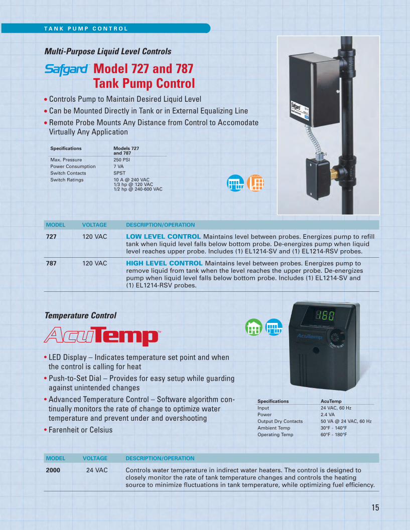
727 120 VAC LOW LEVEL CONTROL Maintains level between probes. Energizes pump to refilltank when liquid level falls below bottom probe. De-energizes pump when liquidlevel reaches upper probe. Includes (1) EL1214-SV and (1) EL1214-RSV probes.
787 120 VAC HIGH LEVEL CONTROL Maintains level between probes. Energizes pump toremove liquid from tank when the level reaches the upper probe. De-energizespump when liquid level falls below bottom probe. Includes (1) EL1214-SV and (1) EL1214-RSV probes.
Multi-Purpose Liquid Level Controls
Model 727 and 787Tank Pump Control
• Controls Pump to Maintain Desired Liquid Level
• Can be Mounted Directly in Tank or in External Equalizing Line
• Remote Probe Mounts Any Distance from Control to AccomodateVirtually Any Application
Specifications Models 727and 787
Max. Pressure 250 PSIPower Consumption 7 VASwitch Contacts SPSTSwitch Ratings 10 A @ 240 VAC
1/3 hp @ 120 VAC1/2 hp @ 240-600 VAC
Specifications AcuTempInput 24 VAC, 60 HzPower 2.4 VAOutput Dry Contacts 50 VA @ 24 VAC, 60 HzAmbient Temp 30°F - 140°FOperating Temp 60°F - 180°F
T A N K P U M P C O N T R O L
• LED Display – Indicates temperature set point and whenthe control is calling for heat
• Push-to-Set Dial – Provides for easy setup while guardingagainst unintended changes
• Advanced Temperature Control – Software algorithm con-tinually monitors the rate of change to optimize watertemperature and prevent under and overshooting
• Farenheit or Celsius
Temperature Control
MODEL VOLTAGE DESCRIPTION/OPERATION
2000 24 VAC Controls water temperature in indirect water heaters. The control is designed toclosely monitor the rate of tank temperature changes and controls the heatingsource to minimize fluctuations in tank temperature, while optimizing fuel efficiency.
Hydrolevel Catalog 2018 Page 15

16
Manifold Fittings
MODEL MAX. PSI DESCRIPTION
1214C-1 250 1" x 1" x (3) 3/4". Three-probe manifold with tri cock and gauge glass tappings.Supplied with control models LCFT 967, 250WC, 250MWC.
711C 35 Two-probe manifold. Supplied with control models 711 and 724.
250C 250 1" x 1" x (3) 3/4". Three-probe manifold. Supplied with control models 250 and 250M.
1" H.P. TEE 250 1" x 1" x 3/4". High Pressure Tee for use with EL1214-SV probe .
1214C-2 250 1" x 1" x 3/4". One-probe manifold.
FOEM-1 160 One-probe manifolds.FOEM-2 160 FOEM-1 is 11⁄2" x 11⁄2" x 3/4"; FOEM-2 is 1" x 1" x 3/4"; FOEM-3 is 11⁄4" x 11⁄4" x 3/4".FOEM-3 160
1214C-1 711C 250C 1214C-21" H.P. TEE FOEM
Probe Options/SpecificationsAdd letters in the chart below to the base model number to specify other probe options. (Example: CG450P)
MODEL PROBE MODELSUFFIX DESIGNATED PROBE DESCRIPTION
SV EL1214-SV 3/4" NPT. Short Inside Dimension. Designed for installation in standardreducing tee and short clearance installations.
SVA EL1220-SV 1/2" NPT. Short Inside Dimension. Designed for installation in standardreducing tee and short clearance installations.
P EL1214-P 3/4" NPT. Long nut for thicker boiler jackets.
A EL1220 1/2" NPT. Same dimensions as standard EL1214.
R EL1214-R 3/4" NPT. Remote mount probe mounted to j-box (standard dimensions).
RA EL1220-R 1/2" NPT. Remote mount probe mounted to j-box (standard dimensions).
Test pressure 1000 PSI, all models.Note: All controls include one EL1214 probe unless otherwise specified.
REMOTEPROBEEL1214-REL1220-R
EL1214 STANDARD 3/4" NPT EL1220 1/2" NPT
EL1214-SV 3/4" NPTEL1220-SV 1/2" NPT
EL1214-P 3/4" NPT
Hydrolevel Catalog 2018 Page 16


