49
Installation & Operation Manual Hydronic Installation & Operation Manual Engineering Specifications GeoSource Hydronic Models RGS-W036 – RGS-W120
Inst
alla
tio
n &
Op
erat
ion
Man
ual
Hyd
ron
ic
Installation & Operation Manual
Engineering Specifications
GeoSource Hydronic
Models RGS-W036 – RGS-W120

This Page Intentionally Left Blank
1
Table of Contents
I. Key & Legend ........................................................................................................................................................................................................................................................................ 2 Key to Model Numbers............................................................................................................................................................................................................................................................... 2
Configuration Options ................................................................................................................................................................................................................................................................ 3 Legend for Tables ....................................................................................................................................................................................................................................................................... 3
II. Warnings & Cautions ............................................................................................................................................................................................................................................................ 4 III. General Information ............................................................................................................................................................................................................................................................. 4
Inspection................................................................................................................................................................................................................................................................................... 4 Storage ....................................................................................................................................................................................................................................................................................... 5 Protection .................................................................................................................................................................................................................................................................................. 5 Pre-Installation Preparation ....................................................................................................................................................................................................................................................... 5
IV. Best Practices ....................................................................................................................................................................................................................................................................... 5
System Sizing .............................................................................................................................................................................................................................................................................. 5
V. System design ....................................................................................................................................................................................................................................................................... 6
Ground Source Design ................................................................................................................................................................................................................................................................ 6 Storage Tanks ............................................................................................................................................................................................................................................................................. 8 Hydronic Side Circulators ........................................................................................................................................................................................................................................................... 8 Circulation Fluid ......................................................................................................................................................................................................................................................................... 9 Expansion Tanks ....................................................................................................................................................................................................................................................................... 10 Application Diagrams ............................................................................................................................................................................................................................................................... 10 Unit location/mounting ............................................................................................................................................................................................................................................................ 10
VI. Electrical ............................................................................................................................................................................................................................................................................. 11
Controller ................................................................................................................................................................................................................................................................................. 11
Compressor Anti-Short Cycle .............................................................................................................................................................................................................................................. 11 Compressor Control ............................................................................................................................................................................................................................................................ 11 Ground Loop Pump / Ground Water Initiation.................................................................................................................................................................................................................... 12 Hydronic Circulator Pump Control ...................................................................................................................................................................................................................................... 12 Reversing Valve Control ...................................................................................................................................................................................................................................................... 12 Compressor Lockouts ......................................................................................................................................................................................................................................................... 12 System Diagnostics ............................................................................................................................................................................................................................................................. 12 24VAC Fuse ......................................................................................................................................................................................................................................................................... 12 Plug Accessory (PA)............................................................................................................................................................................................................................................................. 12 Alarm Output ...................................................................................................................................................................................................................................................................... 13
VII. Heat Pump Commissioning ................................................................................................................................................................................................................................................. 13
Maintenance ............................................................................................................................................................................................................................................................................ 14
VIII. Accessories ......................................................................................................................................................................................................................................................................... 14
Room Thermostat .................................................................................................................................................................................................................................................................... 14 Desuperheater ......................................................................................................................................................................................................................................................................... 14
IX. Engineering Specifications .................................................................................................................................................................................................................................................. 16
Performance Ratings ................................................................................................................................................................................................................................................................ 16 Performance Data .................................................................................................................................................................................................................................................................... 18 Physical Dimensions ................................................................................................................................................................................................................................................................. 32 Electrical Data .......................................................................................................................................................................................................................................................................... 33 Water Coil Pressure Drop Ratings ............................................................................................................................................................................................................................................. 34
X. Figures ................................................................................................................................................................................................................................................................................ 36 XI. Troubleshooting ................................................................................................................................................................................................................................................................. 41 Wiring Diagram ................................................................................................................................................................................................................................................................... 45

2
I. KEY & LEGEND
KEY TO MODEL NUMBERS
R G S - W 036 - A R X - P C - XXX
[Application]
R = Series
[Build]
G = GeoSource
[Compressor]
S = Single Stage
[Configuration]
W = Water (hydronic)
[Unit Size]
036 = 3 Ton
048 = 4 Ton
060 = 5 Ton
072 = 6 Ton
084 = 7 Ton
120 = 10 Ton
[Electrical Supply]
A = 208/230V-60Hz, Single Phase
D = 208/230V–50HZ, Three Phase*
M = 208/230V-60Hz, Three Phase*
N = 460V-60Hz, Three Phase* *(Special order, lead time varies. Not available
on all sizes, contact Customer Service)
[Special]
Mfg Code
[Heat Exchanger]
C = Copper
N = Cupronickel source coil
[Blower]
X = none
[Domestic Hot Water]
S = Desuperheater
X = none
[Air Return]
L = Left Return (vertical)
R = Right Return (vertical)
X = none

3
CONFIGURATION OPTIONS
Standard Special Order - Not Available
Model Suffix Description 036 048 060 072 084 120
RGS – W*** - A** - ** - *** Standard, 208/230-1, 60 Hz
RGS – W*** - **X - ** - *** Standard, No Desuperheater
RGS – W*** - **S - ** - *** Desuperheater
RGS – W*** - *** - *C - *** Standard, Copper
RGS – W*** - *** - *N - *** Cupronickel source coil
RGS – W*** - M** - ** - *** 208/230-1, 60 Hz, Three Phase
RGS – W*** - N** - ** - *** 460V-60Hz, Three Phase
LEGEND FOR TABLES
BTU/hr Heating or cooling capacity GPM Gallons Per Minute
CAP Capacity HE Heat Extracted
COP Coefficient of performance (BTU/hr out : BTU/hr in) HR Heat Rejected
CFM Cubic feet per minute HYD Hydronic
DB Dry-bulb entering air temperature kW Kilowatt
DEWT Demand Entering Water Temperature LLTC Liquid Line Temperature Cooling
DHW Demand Hot Water LLTH Liquid Line Temperature Heating
DLWT Demand Leaving Water Temperature LRA Locked-rotor amperage
dP Pressure drop across heat pump LWT Leaving water temperature
DSH Desuperheater MBTU/hr Btu/hr x 1000
EER Energy efficient ratio (BTU/hr CAP : watts in) RLA Rated-load amperage
EWT Entering water temperature SLT Suction Line Temperature
FLA Full-load amperage VA Volt-amperes
GND Ground WB Wet-bulb entering air temperature
4
II. WARNINGS & CAUTIONS
Note – Always refer to the inside of the front
cover for the correct wiring diagram, and always
refer to the nameplate on the exterior of the cabinet
for the correct electrical specifications.
WARNING – Service of refrigerant-based
equipment can be hazardous due to elevated
system pressures and hazardous voltages. Only
trained and qualified personnel should install,
repair or service. Installer is responsible to ensure
that all local electrical, plumbing, heating and air
conditioning codes are followed.
WARNING – ELECTRICAL SHOCK CAN
CAUSE PERSONAL INJURY OR DEATH.
Disconnect all power supplies before installing or
servicing electrical devices. Only trained and
qualified personnel should install, repair or service
this equipment.
WARNING – THE UNIT MUST BE PROPERLY
GROUNDED!
The main electrical service must be protected by a
fuse or circuit breaker and be capable of providing
the amperes required by the unit at nameplate
voltage. All wiring must comply with the national
electrical code and/or any local codes that may
apply. Access to the line voltage contactor is
through the knockouts provided on the side of the
heat pump as labeled. Route EMT or flexible
conduit with appropriate size and type of wire.
Ensure adequate supply wiring to minimize the
level of dimming lights during compressor startup
on single-phase installations. Some dimming is
normal upon compressor start-up.
CAUTION – Route field electrical wiring to
avoid contact with electrically live bare metal parts
inside the electrical box.
CAUTION – Three-phase units must be wired
properly to ensure proper compressor rotation.
Improper rotation may result in compressor
damage. An electronic phase sequence indicator
must be used to check supply-wiring phases.
Also, the “Wild” leg of the three-phase power must
be connected to the middle leg on the contactor.
WARNING –Verify refrigerant type before
servicing. The nameplate on the heat pump
identifies the type and the amount of refrigerant.
All refrigerant removed from these units must be
reclaimed by following accepted industry and
agency procedures.
CAUTION – Ground and hydronic loops must
be freeze protected. Insufficient amounts of
antifreeze may cause severe damage and may void
warranty. Hydronic loop antifreeze must be non-
flammable. Never operate with ground or hydronic
loop flow rates less than specified. Continuous
operation at low flow or no flow may cause severe
damage and may void warranty.
III. GENERAL INFORMATION
INSPECTION
Equipment should be inspected on receipt to assure
that damage has not occurred during shipment of
the unit. Carefully check the shipping company bill
of lading against the packing slip to verify that all
units and accessory packages have been received.
Inspect each package for physical damage and
ensure that the carrier makes notation of any
damage or missing packages on bill of lading
records. Pictures of the damage are
recommended. Concealed damage should be
reported to the shipping company immediately.
5
STORAGE
Unit should be stored in a clean, dry location in the
original shipping packaging. Units shall be stored
in an upright position and should not be stacked
unless noted on the shipping packaging.
PROTECTION
Units should be protected when on the building
site from damage and contamination. Keep units
covered or in original shipping packaging during
job site construction. All physical connections (air
supply and return, piping, electrical) should be
protected and covered/capped prior to installation.
PRE-INSTALLATION PREPARATION
Locate the unit where there is adequate ventilation
and room for servicing; minimum 12” clearance on
all sides is recommended. Units should be placed
on a level surface on a vibration–absorbing pad
slightly larger than the base of the unit. Care
should be taken to use the proper duct size, piping
is not hard-plumbed to the unit, and any sound or
vibration is not transmitted into the surroundings.
Units are designed for indoor installation only
where the ambient temperature remains above
45°F. Do not use the heat pump for initial heating
of the building during construction. Operating the
heat pump during construction or renovation will
subject the unit to contamination, potentially
resulting in failure of the unit. Starting the heat
pump in a cold environment may flush lubricant
from the compressor resulting in compressor damage
and ultimately, unit failure.
Review the electrical data on the nameplate to
assure that the correct unit has been shipped
Carefully remove any packing material from
the outside and inside of the unit and inspect
for any concealed damage
Inspect electrical connections for cleanliness
and attachment
Inspect liquid connections to assure that any
debris has been removed and caps are removed
as appropriate.
IV.BEST PRACTICES
SYSTEM SIZING
Selecting the unit capacity of a hydronic
geothermal heat pump requires four things:
Building Heat Loss / Heat Gain.
Ground Sources and Design Water Temperatures.
Temperature Limitations.
Hydronic-Side Operating Temperatures.
BUILDING HEAT LOSS/HEAT GAIN
The space load must be estimated accurately for
any successful HVAC installation. There are many
guides or computer programs available for
estimating heat loss and gain, including the
Manual J, and others. After the heat loss and gain
analysis is completed, Entering Water
Temperatures (EWT’s) are established, and
hydronic-side heating conditions are determined.
The heat pump can now be selected using the
hydronic heat pump data found in the Engineering
Specifications (Section XI). Choose the capacity of
the heat pump based on both heating and cooling
loads.
GROUND SOURCES AND DESIGN WATER
TEMPERATURES
Ground sources include the Ground Water
(typically a well) and the Ground Loop varieties.
Water flow-rate requirements vary based on

6
configuration. The Engineering Specifications
section provides capacities at different loop
entering water temperatures and hydronic entering
water temperatures.
GROUND LOOP SYSTEMS
See figure 2
Loop systems use high-density polyethylene pipe
buried underground to supply a tempered water
solution back to the heat pump. Ground loops
operate at higher flow rates than ground water
systems because the loop Entering Water
Temperature (EWT) is lower. EWT affects the
capacity of the unit in both heating and cooling
modes, and loops in cold climates are normally
sized to supply wintertime EWT to the heat pump
down to 25°F.
GROUND WATER SYSTEMS
See Figure 3
Note – If a heat pump is installed with ground
water, it should have a Cupro-Nickel water coil.
Cupro-Nickel water coils withstand well water
much better than standard water coils.
TEMPERATURE LIMITATIONS
Be aware of the operating range of the geothermal
system when sizing the particular heat pump to
avoid premature equipment failure. Operating
outside of these limitations may cause severe
damage to the equipment and may void warranty.
CAUTIONS: Reference tables in section XI for
acceptable operating conditions.
HYDRONIC SIDE SYSTEM DESIGN
This section deals with some common practices
used when coupling the Enertech GeoSource
hydronic heat pumps to the space conditioning
heat exchanger. There are so many possible
applications for hydronic systems that they cannot
all be covered in this text.
Note – Systems must be constructed to
appropriate codes and according to accepted
plumbing practices.
Caution – Always use piping rated for the
application. Check local codes for compliance.
Important – Pressure/Temperature port fittings
are highly recommended for installation in the
entering & leaving hydronic lines of the heat pump.
V. SYSTEM DESIGN
GROUND SOURCE DESIGN
GROUND LOOP INSTALLATION
A Ground Loop system circulates the same
antifreeze solution through a closed system of
high-density underground polyethylene pipe. As
the solution passes through the pipe, it collects
energy (in the heating mode) from the relatively
warm surrounding soil through the pipe and into
the relatively cold solution. The solution circulates
to the heat pump, which transfers energy with the
solution, and then the solution circulates back
through the ground to extract more energy.
CAUTION – Ground Loops must be properly
freeze protected. Insufficient amounts of antifreeze
may result in a freeze rupture of the unit or can
cause unit shutdown problems during cold
weather operation. Propylene glycol is a common
antifreeze solution. GeoSystems proprietary
Geothermal Transfer Fluid (GTF) is methanol-
based antifreeze and should be mixed 50% with

7
water to achieve freeze protection of 12°F.
Propylene glycol antifreeze solution should be
mixed 25% with water to obtain a 15°F freeze
protection.
Important – Do not mix more than 25%
propylene glycol with water in an attempt to
achieve lower than 15°F freeze protection, since
more concentrated mixtures of propylene glycol
become too viscous at low temperatures and will
become more difficult to pump through the earth
loop. Horizontal loops typically use GTF, and
vertical loops typically use propylene glycol.
Note – Always check State and Local codes for any
special requirements on antifreeze solutions.
CAUTION – Never operate with flow rates less
than specified. Low flow rates, or no flow, may
cause the unit to shut down on a pressure lockout
or may cause a freeze rupture of the heat
exchanger.
Important– Pressure/Temperature (P/T) ports
are highly recommended for installation in the
entering and leaving water lines of the heat pump
(see figure 2). A thermometer can be inserted into
the P/T ports to check entering and leaving water
temperatures. A pressure gauge can also be
inserted into these P/T ports to determine the
pressure differential between the entering and
leaving water. This pressure differential can then
be compared to the specification data on each
particular heat pump to confirm the proper flow
rate of the system.
Filling and purging a loop system are very
important steps to ensure proper heat pump
operation. Each loop must be purged with enough
flow to ensure two feet per second flow rate in each
circuit in the loop. This normally requires a 1½ to 3
HP high-head pump to circulate fluid through the
loop to remove all the air out of the loop. Allow the
pump to run 10 to 15 minutes after the last air
bubbles have been removed. After purging is
completed, add the calculated proper amount of
antifreeze to give a 12°F to 15°F freeze
protection. After antifreeze has been installed and
thoroughly circulated, it should be measured with
a hydrometer, refractometer, or any other device to
determine the actual freezing point of the solution.
The purge pump can be used to pressurize the
system for a final static pressure of 30-40 psig after
the loop pipe has had enough time to stretch. In
order to achieve the 30 to 40 psig final pressure, the
loop may need to be initially pressurized to 60-65
psig. This static pressure may vary 10 psig from
heating to cooling season, but the pressure should
always remain above 20 psig, to ensure circulation
pumps do not cavitate or pull air into the system.
Contact your local installer, distributor or factory
representative for more information.
GROUND WATER INSTALLATION
Since water is the source of energy in the winter
and the energy sink in the summer, a good water
supply is possibly the most important requirement
of a geothermal heat pump system installation.
A Ground Water system gets its name from the
open discharge of water after it has been used by
the heat pump. A well must be available that can
supply all of the water requirements of the heat
pump for up to 24 hours/day on the coldest winter
day plus any other water requirements drawing
off of that same well.
A bladder type pressure tank with a “draw down”
of at least 1 ½ times the well pump capacity must
be installed on the supply side of the heat pump.
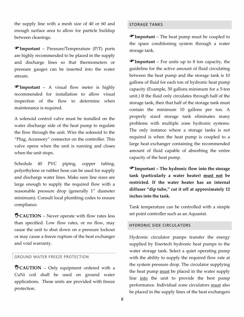
Important – A screen strainer must be placed on
8
the supply line with a mesh size of 40 or 60 and
enough surface area to allow for particle buildup
between cleanings.
Important – Pressure/Temperature (P/T) ports
are highly recommended to be placed in the supply
and discharge lines so that thermometers or
pressure gauges can be inserted into the water
stream.
Important – A visual flow meter is highly
recommended for installation to allow visual
inspection of the flow to determine when
maintenance is required.
A solenoid control valve must be installed on the
water discharge side of the heat pump to regulate
the flow through the unit. Wire the solenoid to the
“Plug, Accessory” connector on the controller. This
valve opens when the unit is running and closes
when the unit stops.
Schedule 40 PVC piping, copper tubing,
polyethylene or rubber hose can be used for supply
and discharge water lines. Make sure line sizes are
large enough to supply the required flow with a
reasonable pressure drop (generally 1” diameter
minimum). Consult local plumbing codes to ensure
compliance.
CAUTION – Never operate with flow rates less
than specified. Low flow rates, or no flow, may
cause the unit to shut down on a pressure lockout
or may cause a freeze rupture of the heat exchanger
and void warranty.
GROUND WATER FREEZE PROTECTION
CAUTION – Only equipment ordered with a
CuNi coil shall be used on ground water
applications. These units are provided with freeze
protection.
STORAGE TANKS
Important – The heat pump must be coupled to
the space conditioning system through a water
storage tank.
Important – For units up to 8 ton capacity, the
guideline for the active amount of fluid circulating
between the heat pump and the storage tank is 10
gallons of fluid for each ton of hydronic heat pump
capacity (Example, 50 gallons minimum for a 5-ton
unit.) If the fluid only circulates through half of the
storage tank, then that half of the storage tank must
contain the minimum 10 gallons per ton. A
properly sized storage tank eliminates many
problems with multiple zone hydronic systems.
The only instance where a storage tanks is not
required is when the heat pump is coupled to a
large heat exchanger containing the recommended
amount of fluid capable of absorbing the entire
capacity of the heat pump.
Important – The hydronic flow into the storage
tank (particularly a water heater) must not be
restricted. If the water heater has an internal
diffuser “dip tube,” cut it off at approximately 12
inches into the tank.
Tank temperature can be controlled with a simple
set point controller such as an Aquastat.
HYDRONIC SIDE CIRCULATORS
Hydronic circulator pumps transfer the energy
supplied by Enertech hydronic heat pumps to the
water storage tank. Select a quiet operating pump
with the ability to supply the required flow rate at
the system pressure drop. The circulator supplying
the heat pump must be placed in the water supply
line into the unit to provide the best pump
performance. Individual zone circulators must also
be placed in the supply lines of the heat exchangers
9
they serve. These pumps are often used as the
on/off control mechanism for the zone they supply
as shown in Figure 4. Zone valves are also
commonly used for this purpose using a common
pump as shown in Figure 5.
CAUTION – Never operate with hydronic flow
rates less than specified. Low flow rates, or no flow,
may cause the unit to shut down on a pressure
lockout or may cause a freeze rupture of the heat
exchanger in cooling mode.
Circulator pumps must be sized to provide the
required flow to a heat pump heat exchanger at its
corresponding system pressure drop calculated
from the pressure drop through the piping, plus
the pressure drop of the water storage tank, and
plus the pressure drop through the heat pump heat
exchanger. See the Engineering Specification
section for water flow requirements and pressure
drop. Use these tables for sizing the circulating
pump between the hydronic side of the heat pump
and a storage tank.
A common problem with circulator pumps is
trapped air in the system. This air accumulates in
the suction port of the circulator causing
cavitations in the pump, which leads to premature
pump failure and noisy operation. The air can be
eliminated by completely purging the system or
by placing an air separator in the plumbing lines.
The entire system must be purged of air during
initial installation and pressurized to a 10-25 psig
static pressure to avoid air entering the system.
This static pressure may fluctuate when going from
the heating to cooling modes but should always
remain above zero. If a leak in the system causes
the static pressure to drop, the leak must be
repaired and the system repurged to assure proper
system operation.
The hydronic side circulator supplying the heat
pump should be controlled to run only when the
compressor runs. If the pump is allowed to
circulate cold water through the system during off
cycles, the refrigerant in the heat pump will
migrate to the hydronic side heat exchanger. This
can cause heat pump starting problems (especially
when this refrigerant migrates into the condenser).
CIRCULATION FLUID
The fluid circulating through the hydronic side of
the geothermal heat pump system is the transfer
medium for the heating and cooling being supplied
to the conditioned space. Selection of this fluid is
very important. Water is the most readily available
fluid but has the drawback of expansion during
freezing which can damage the system. System
operation in the cooling mode, extended power
interruption to a structure, or disabling of an
outside zone (such as a garage floor) provides the
opportunity for freezing the circulating fluid.
CAUTION – the hydronic side of the system
must be freeze protected to reduce the risk of a
freeze rupture of the unit. A propylene glycol
based antifreeze (readily available through HVAC
wholesalers) and water solution is recommended.
A non-flammable antifreeze solution is
recommended for use on any hydronic system
where heat is being added to the system for
structural heating purposes. Freeze protection for
the hydronic side fluid down to 18°F (20%
propylene glycol by volume in water) is
recommended for most indoor applications. Forty
percent (40%) propylene glycol in water (-5°F freeze
protection) is recommended by radiant tube
manufactures for snow melt applications to protect
the tubing from expansion in outdoor applications.
Using over 40% in hydronic side applications can
cause pumping problems due to high viscosity.

10
The water being added to the system should have
100-PPM grain hardness or less. If poor water
conditions exist on the site, softened water is
recommended, or acceptable water should be
brought in. Bacteria or algae growth in the water is
a possibility at the temperatures produced in the
heating system and can cause buildup on hydronic
side heat exchanger surfaces, reducing the
efficiency of the system or causing the heat pump
to run at higher head pressures and possibly lock
out. Boiler system conditioner can reduce bacteria
growth in the system.
EXPANSION TANKS
Expansion tanks must be used in the hydronic
distribution side of the water-to-water system to
absorb the change in pressure of the closed system
due to the change in temperature when heat is
supplied to the system. Diaphragm-type expansion
tanks should be used. EPDM diaphragm tanks are
compatible with glycol-based antifreeze fluids
(butyl rubber diaphragms will slowly dissolve with
glycol-based antifreezes). Expansion tanks from 1
to 10 gallons are generally used for the distribution
system in residential applications.
APPLICATION DIAGRAMS
Figures 1 through 5 show the components of a
hydronic heat pump system discussed above used
in some common applications. These figures by no
means represent all the possible hydronic heat
pump applications, but they do show some
important principals that can be applied to any
system.
UNIT LOCATION/MOUNTING
CAUTION – Units must be kept in an upright
position during transportation or installation, or
severe internal damage may occur. Never transport
a heat pump on its side or back.
CAUTION – Do not use this unit during
construction. Dust and debris may contaminate
electrical and mechanical components; resulting in
damage.
Important – To ensure easy removal and
replacement of access panels, leave panels secured
in place until the unit is set in place and leveled.
Important – Locate the unit in an indoor area
where the ambient temperature will remain above
45°F. Service is done primarily from the front. Top
and rear access is desirable and should be provided
when possible. Minimum clearance of 12” on each
side is recommended.
Important – A field installed drain pan is
required under the entire unit if accidental water
discharge could damage surrounding floors, walls
or ceilings. Check local codes for compliance.
CAUTION – Do not mount components or pipe
to the exterior of the heat pump cabinet.
Important – Units must be mounted on a
vibration absorbing pad slightly larger than the
base to provide isolation between the unit and the
floor. Water supply pumps shall not be hard
plumbed directly to the unit with copper pipe; this
could transfer vibration from the water pump to
the refrigeration circuit, causing a resonating
sound. The use of flexible water connections is
recommended to eliminate transfer of vibration
wherever possible.
CAUTION – Always use plastic male fittings
into plastic female or into metal female fittings.
Never use metal male fittings into plastic female
fittings. On metal-to-metal fittings; use pipe thread
compound, do not use pipe thread tape. Hand

11
tighten first, and then only tighten an additional ½
turn with a tool if necessary.
On plastic fittings, always use 2 to 3 wraps of pipe
thread tape. Hand tighten first, and then only
tighten an additional ½ turn with a tool if
necessary. Do not over-tighten, as damage may
occur.
VI. ELECTRICAL
Note – Always refer to the inside of the front panel
for the correct wiring diagram.
Important – If the system’s external controls
require more power than shown in the engineering
specification (see Engineering Specifications
section), an external transformer and isolation
relays should be used. In contrast, Figure 4 shows a
fan coil system with its own power supply, which
must interface to the heat pump to put the heat
pump into the cooling mode. This can be
accomplished by using the fan coil’s independent
power supply to energize the coil of an isolation
relay with contacts located in heat pump's control
circuit.
Important – Miswiring of 24Vac control voltage
on system controls can result in transformer
burnout.
Important – Units with a dual voltage rating
(example, 208/230) are factory-wired for the higher
voltage (example, 230). If connected to a power
supply having the lower voltage, change the wiring
to the transformer primary to the correct lead;
otherwise premature failure, or inability to operate
the control components may occur.
CONTROLLER
The heat pump controller receives a signal from the
remote hydronic control, initiates the correct
sequence of operation for the heat pump, and
performs the following functions:
1) Compressor Anti-Short Cycle
2) Compressor Control
3) Ground Loop Pump / Ground Water Initiation
4) Compressor Staging
5) Hydronic Circulator Pump Control
6) Reversing Valve Control
7) Compressor Lockouts
8) System Diagnostics
9) 24Vac Fuse
10) Plug Accessory
11) Alarm Output
COMPRESSOR ANTI-SHORT CYCLE
An Anti-Short-Cycle (ASC) is a delay period
between the time a compressor shuts down and
when it is allowed to come on again. This protects
the compressor and avoids nuisance lockouts for
these two conditions;
1. A 70 to 130-second random time-out period
occurs before a re-start after the last shutdown.
2. A 4-minute, 25-second to 4-minute, 45-second
random-start delay occurs immediately after
power is applied to the heat pump. This occurs
only after reapplying power to the unit. To
reduce this timeout delay while servicing the
unit, apply power, disconnect and reapply
power very quickly to shorten the delay.
COMPRESSOR CONTROL
When 24Vac is applied to the Y terminal on the
controller wiring block, the controller decides,

12
based on lockout and anti-short-cycle periods,
when to turn on the compressor contactor. The M1
output of the controller energizes the contactor(s)
until 24Vac is removed from the Y terminal.
GROUND LOOP PUMP / GROUND WATER
INITIATION
On ground loop systems, a M1 output from the
controller will energize the contactor to start the
compressor and the ground loop pump. On ground
water systems, the M1 output will also energize the
ground water solenoid valve through the “Plug
Accessory” connector.
HYDRONIC CIRCULATOR PUMP CONTROL
The hydronic circulator pump is energized either
directly with the compressor contactor through the
internal pump relay (RP) and 3-pole terminal block
(BP) or through an isolation relay having its 24Vac
coil wired to the Y and X terminals.
REVERSING VALVE CONTROL
When 24Vac is applied to the O terminal on the
wiring block, the controller energizes its O output
to provide 24Vac power to the reversing valve to
switch the refrigerant circuit to the cooling mode.
COMPRESSOR LOCKOUTS
The controller will lock out the compressor if either
of the following switches open: 1) high-pressure 2)
low- pressure on ground loop or on ground water,
or 3) high discharge refrigerant temperature. A
lockout condition means that the unit has shut itself
down to protect itself, and will not come back on
until power has been disconnected (via the circuit
breaker) to the heat pump for one minute.
Problems that could cause a lockout situation
include:
1. Low water flow or extreme water temperatures.
2. Cold ambient air temperature conditions.
3. Internal heat pump operation problems.
CAUTION – Repeated reset may cause severe
damage to the system and may void warranty. The
cause of the lockout must be determined and
corrected.
If a lockout condition exists, the heat pump should
not be reset more than once; and a service
technician should be called immediately.
SYSTEM DIAGNOSTICS
The controller is equipped with diagnostic LED
lights that indicate the system status at any
particular time. The lights indicate the following
conditions:
GREEN = 24 Volt system power
YELLOW = Fault or Lockout
RED = Anti-short-cycle mode
If a set point controller installed with the heat pump
system has a lockout indicator, the controller will
send a signal from L on the terminal strip to a LED on
the thermostat to indicate a lockout condition.
24VAC FUSE
The controller has a glass-cartridge fuse located on
the circuit board adjacent to the 24VAC power
connector. The green system power LED will be off
if this fuse is open. A spare fuse is located in the
saddle attached to the side of the 24VAC power
connector.
Note – Ensure the new fuse fits tightly in the fuse
clips after replacement.
PLUG ACCESSORY (PA)
The Plug Accessory output is internally connected
to the M1 output and is energized whenever M1
turns on the compressor contactor. The maximum

13
rating of this output is 10VA sealed and 20VA
inrush and is typically intended to power a 24Vac
ground water solenoid valve.
ALARM OUTPUT
This output is a 2-position screw terminal
connector identified as “Fault Test” on the
controller board and as DO on the wiring
diagram. It is an isolated dry contract output (0.1
ohm resistance) that closes during a controller
lockout and is intended for use as an input to a
dial-out type of monitoring system. The maximum
electrical rating is 2mA up to 30Vac or 50mA up to
40Vdc.
VII. HEAT PUMP COMMISSIONING
Before applying power to the heat pump, check the
following items:
Water supply plumbing to the heat pump is
completed and operating. Manually open the
water valve on well systems to check flow.
Make sure all valves are open and air has been
purged from a loop system. Never operate the
system without correct water supply flow on
either the ground side or the hydronic side.
All high voltage and all low voltage wiring is
correct and checked out, including wire sizes,
fuses and breakers. Set system to the “OFF”
position.
Note – the heat pump is located in a warm area
(above 45°F). (Starting the system with low
ambient temperature conditions is more
difficult and may cause low-pressure lockout.)
Do not leave the area until the space is brought
up to operating temperatures.
Hydronic side water temperatures are warm
enough (50°F or above) to start in the heating
mode.
Apply power to the unit. A 4-minute and 35-second
delay on power-up is programmed into the
controller before the compressor will operate.
During this time, the pump relay will energize the
hydronic side-circulating pump. Verify the flow
rate and temperature of the hydronic side flow.
The following steps will ensure the system is
heating and cooling properly. After the initial time-
out period, the red indicator light on the controller
will shut off. The heat pump is now ready for
operation.
Turn the heating set point to its highest
temperature setting, and place the system to run
in heating. The compressor should start 1 to 2
seconds later.
After 5 minutes of heating operation, check
hydronic-side return and supply water
temperatures. A water temperature rise of 10°F
to 15°F is normal (variation in water
temperature and water flow rate can cause slight
variations). A single pressure gauge can be used
to check the fluid pressure drop through the
heat exchangers to ensure proper flow for the
system.
Set the system to the “OFF” position. The
compressor will shut down in 1 to 2 seconds.
Next, turn the set point to its lowest setting. If
applicable, place the system to run in cooling.
The compressor will start after an anti-short-
cycle period of 70 to 130 seconds from its last
shutdown. The anti-short-cycle period is
indicated by the red light on the controller.
After 5 minutes of cooling operation, check
hydronic side return and supply water
temperatures. A water temperature drop of

14
10°F to 15°F is normal (variation in water
temperature and water flow can cause slight
variations). A single pressure gauge can be
used to check the fluid pressure drop through
the heat exchangers to ensure proper flow for
the system.
Set the system and the set point for normal
operation.
Instruct the owner on correct operation of the
entire heat pump system. The unit is now
operational.
MAINTENANCE
Properly installed, the Enertech GeoSource heat
pump requires only minor maintenance such as
periodic cleaning of the ground water heat
exchanger for heat pumps installed in ground-
water applications. Regular service checkups with
your Enertech dealer are recommended. Any major
problems with the heat pump system operation
will be indicated on the lockout lights. Dealers are
trained to troubleshoot lockout occurrence.
CAUTION – During refrigerant evacuation for a
system not having antifreeze protection in either
the ground-side or the hydronic-side, water in the
unprotected heat exchanger must be removed or
continuously flowing to avoid a potential heat
exchanger failure caused by freeze rupture.
The heat pump controller will display a system
lockout. If lockout occurs, follow the procedure
below:
1) Determine and record which indicator lights on
the Controller are illuminated. (Refer to Section
Troubleshooting Section for more information
on possible causes of Lockout Conditions.)
2) Check for correct water supply from the ground
loop or ground water system.
3) Check for correct water supply on the hydronic
side.
4) Reset the system by disconnecting power at the
circuit breaker for one minute and then restart.
5) If shutdown reoccurs, Call your Enertech
dealer. Do not continuously reset the lockout
condition or serious damage may occur.
Note – Improper fluid flows or incorrect
antifreeze levels are the cause of almost all
lockouts.
VIII. ACCESSORIES
ROOM THERMOSTAT
Installations may include a wide variation of
available electronic room thermostats, and most of
them must be configured by the Installer and
checked out after installation. If you have
questions, please refer to the thermostat installation
manual.
DESUPERHEATER
A GeoSource heat pump equipped with a double-
wall vented desuperheater can provide
supplemental heating of a home’s domestic hot
water heating by stripping a small amount of
energy from the superheated gas leaving the
compressor and transferring the heat to a hot water
tank. A desuperheater pump, manufactured into
the unit, circulates water from the domestic hot
water tank, heats it and returns it to the tank.
The desuperheater only provides supplemental
domestic water heating when the compressor is
already running. Because the desuperheater is
using some energy from the heat pump to heat
water, the heat pump’s capacity in the winter is
about 10% less than a unit without a desuperheater.
CAUTION– Running the desuperheater pump
without water flow will damage the pump. A fuse

15
is attached to the fuse holder and must be
inserted in the fuse holder after the desuperheater
is purged and operational.
Important – Do not insert the fuse until water
flow is available and the desuperheater is
completely purged of air, or the pump may be
damaged. Remove the fuse to disable the pump if
the desuperheater isn’t in operation.
All air must be purged from the desuperheater
plumbing before the pump is engaged. To purge
small amounts of air from the lines, loosen the
desuperheater pump from its housing by turning
the brass collar. Let water drip out of the housing
until flow is established, and re-tighten the brass
collar. Using 1/2-inch or larger copper tubing from
the tank to the desuperheater inlet is required to
keep water velocities high, avoiding air pockets at
the pump inlet. An air vent in the inlet line can also
help systems where air is a problem. If one is used,
mount it near the desuperheater inlet roughly 2-1/2
inches above the horizontal pipe. Shutoff valves
allow access to the desuperheater plumbing
without draining the hot water tank. Keep the
valves open when the pump is running.
Hot water tank maintenance includes periodically
opening the drain on the hot water tank to remove
deposits. If hard water, scale, or buildup causes
regular problems in hot water tanks in your area,
it may result in a loss of desuperheater
effectiveness.
CAUTION – Insulated copper tubing must be
used to run from the water tank to the
desuperheater connections on the side of the unit.
Desuperheater must be plumbed in copper tubing.
The built-in desuperheater pump can provide the
proper flow to the desuperheater if the total
equivalent length of straight pipe and connections
is kept to a maximum of 90 feet of 1/2-inch type L
copper tubing (or a combination of approximately
60 feet with typical elbows and fittings). This
tubing can be connected to the water tank in two
ways:
METHOD 1
Using a desuperheater tee installed in the drain at the
bottom of the water heater (See Figure 6). This is the
preferred method for ease of installation, comfort
and efficiency. The tee eliminates the need to tap
into the domestic hot water lines and eliminates
household water supply temperature variations
that could occur from connecting to the hot water
pipes. Poor water quality may restrict the
effectiveness of the desuperheater tee by plugging
it with scale or buildup from the bottom of the
tank, restricting water flow.
METHOD 2
Taking water from the bottom drain and returning it to
the cold water supply line (See Figure 7). This method
maintains the same comfort and efficiency levels
but increases installation time and cost.
Important – This method requires a check valve
in the return line to the cold water supply to
prevent water from flowing backwards through the
desuperheater when the tank is filling. Water
passing through the pump backwards damages the
rotor's bearing, which reduces pump life and
causes noise problems in the pump. Note – A
spring-type check valve with a pressure-drop
rating of 1/2 psig or less is recommended.

16
IX. ENGINEERING SPECIFICATIONS
PERFORMANCE RATINGS
Heating Performance Data (Tested in accordance with ASHRAE/AHRI/ ISO Standard 13256-2)
Models Application Source
EWT (°F)
Load
EWT (°F)
Entering GPM
(source & load)
Total Heat
Output
(MBH)
Heat of
Absorption
(MBH)
Total Heat
Pump Watts COP
RGS-W036 Ground Water 50°F
104°F 9 35.5 25.0 2,600 3.7
Ground Loop 32°F * 29.3 18.6 2,700 3.2
RGS-W048 Ground Water 50°F
104°F 12 57.0 41.0 4,010 3.9
Ground Loop 32°F * 43.9 29.2 4,000 3.1
RGS-W060 Ground Water 50°F
104°F 15 64.9 48.1 3,300 3.6
Ground Loop 32°F * 53.0 34.6 4,888 3.2
RGS-W072 Ground Water 50°F
104°F 18 81.0 53.6 5,670 4.0
Ground Loop 32°F * 65.5 34.6 5,660 3.4
RGS-W084 Ground Water 50°F
104°F 20 89.0 62.1 6,850 4.1
Ground Loop 32°F * 74.2 45.4 6,730 3.1
RGS-W120
Ground Water 50°F
104°F 30
118.1 80.0 9,650 3.4
Ground Loop 32°F * 100.1 64.2 10,040 2.8
Ground Water 50°F 59.0 35.0 4,300 3.6
Ground Loop 41°F 57.5 29.1 4,900 3.4
* Antifreeze required

17
Cooling Performance Data (Tested in accordance with ASHRAE/AHRI/ ISO Standard 13256-2)
Models Application Source
EWT (°F)
Load
EWT (°F)
Entering GPM
(source & load)
Total Heat
Output
(MBH)
Heat of
Rejection
(MBH)
Total Heat
Pump Watts EER
RGS-W036 Ground Water 59°F
53.6°F 9 37.3 42.8 1,400 23.5
Ground Loop 77°F 34.7 41.1 1,900 18.2
RGS-W048 Ground Water 59°F
53.6°F 12 56.3 67.0 2,280 23.3
Ground Loop 77°F 52.8 62.8 2,775 17.7
RGS-W060 Ground Water 59°F
53.6°F 15 69.0 78.4 2,710 24.0
Ground Loop 77°F 63.7 72.6 3,543 18.0
RGS-W072 Ground Water 59°F
53.6°F 18 78.3 90.2 3,300 21.1
Ground Loop 77°F 65.5 84.0 4,200 17.7
RGS-W084 Ground Water 59°F
53.6°F 20 88.7 101.8 5,000 20.8
Ground Loop 77°F 83.6 99.6 5,230 16.1
RGS-W120
Ground Water 59°F
53.6°F 30
110.8 124.5 7,900 21.0
Ground Loop 77°F 105.6 103.2 7,250 14.5
Ground Water 59°F 65.8 77.4 2,500 22.0
Ground Loop 68°F 63.5 73.1 3,200 19.8
1 AHRI test point

18
PERFORMANCE DATA
RGS-W036 HEATING PERFORMANCE DATA
GROUND HYD LWT °F
Hydronic Flow – 7 GPM 2.0 PSIG dP, 4.6 FT dP
Hydronic Flow – 9 GPM 3.2 PSIG dP, 7.4 FT dP
Refrigerant Pressure
EWT °F GPM dP psig dP ft TEMP RISE
CAP kBTUh
PWR kW
COP HE
kBTUh
TEMP RISE
CAP kBTUh
PWR kW
COP HE
kBTUh
Suction Pressure
Head Pressure
25 9 3.2 7.4
115 6.8 23.9 2.8 2.5 14.2 5.3 24.0 2.8 2.5 14.5
55 - 75
390 - 420
100 7.0 24.4 2.4 2.9 16.1 5.4 24.5 2.4 3.0 16.4 330 - 355
85 7.1 24.9 2.0 3.6 18.0 5.6 25.0 2.0 3.7 18.2 268 - 295
70 7.3 25.5 1.6 4.6 19.9 5.7 25.6 1.6 4.7 20.1 210 - 235
30 9 3.2 7.4
115 7.3 25.7 2.9 2.6 15.9 5.7 25.8 2.8 2.7 16.3
65 - 85
390 – 425
100 7.5 26.3 2.4 3.1 17.9 5.9 26.4 2.4 3.2 18.2 335 – 360
85 7.7 26.8 2.0 3.8 19.8 6.0 26.9 2.0 4.0 20.1 270 – 305
70 7.8 27.4 1.6 4.9 21.8 6.1 27.5 1.6 5.0 22.0 210 – 235
35 9 3.2 7.4
115 7.9 27.5 2.9 2.8 17.7 6.1 27.6 2.8 2.9 18.0
70 - 90
390 – 430
100 8.0 28.1 2.5 3.4 19.7 6.3 28.2 2.4 3.4 20.0 335 – 365
85 8.2 28.7 2.0 4.1 21.7 6.4 28.8 2.0 4.2 22.0 270 – 310
70 8.4 29.3 1.6 5.2 23.7 6.5 29.4 1.6 5.4 24.0 210 – 240
40
7 2 4.6
115 8.2 28.6 2.8 2.9 18.9 6.4 28.7 2.8 3.0 19.3
70 - 95
390 – 430
100 8.3 29.2 2.4 3.5 20.9 6.5 29.3 2.4 3.6 21.3 330 – 370
85 8.5 29.9 2.0 4.3 22.9 6.7 30.0 2.0 4.5 23.3 270 – 310
70 8.7 30.5 1.6 5.5 25.0 6.8 30.6 1.6 5.7 25.3 200 – 250
9 3.2 7.4
115 8.4 29.3 2.9 3.0 19.5 6.5 29.4 2.8 3.1 19.8
75 - 100
395 – 430
100 8.5 29.9 2.5 3.6 21.5 6.7 30.0 2.4 3.7 21.8 335 – 370
85 8.7 30.6 2.0 4.4 23.6 6.8 30.7 2.0 4.5 23.9 275 – 310
70 8.9 31.2 1.6 5.6 25.7 7.0 31.4 1.6 5.8 25.9 205 – 250
45
6 1.6 3.7
115 8.4 29.4 2.8 3.1 19.8 6.6 29.5 2.7 3.2 20.2
65 - 95
390 – 430
100 8.6 30.1 2.4 3.6 21.8 6.7 30.2 2.3 3.8 22.2 330 – 370
85 8.8 30.7 2.0 4.5 23.9 6.9 30.8 1.9 4.6 24.2 270 – 310
70 9.0 31.4 1.6 5.8 25.9 7.0 31.5 1.6 5.9 26.2 200 – 250
7 2 4.6
115 8.7 30.3 2.9 3.1 20.6 6.8 30.8 2.8 3.2 21.3
70 - 100
395 – 430
100 8.9 31.0 2.4 3.7 22.7 7.0 31.4 2.4 3.9 23.3 335 – 370
85 9.1 31.7 2.0 4.6 24.8 7.1 32.1 2.0 4.8 25.4 275 – 310
70 9.2 32.4 1.6 5.9 26.9 7.3 32.8 1.6 6.1 27.5 205 - 250
9 3.2 7.4
115 8.9 31.1 2.9 3.2 21.2 6.9 31.2 2.8 3.2 21.6
75 - 100
400 - 430
100 9.1 31.8 2.5 3.8 23.3 7.1 31.9 2.4 3.9 23.7 340 - 370
85 9.3 32.5 2.1 4.6 25.5 7.2 32.6 2.0 4.8 25.8 280 - 310
70 9.5 33.1 1.6 6.0 27.6 7.4 33.3 1.6 6.1 27.8 210 - 250
50
6 1.6 3.7
115 8.9 31.1 2.8 3.2 21.4 6.9 31.2 2.8 3.3 21.8
75 - 100
395 - 430
100 9.1 31.8 2.4 3.9 23.5 7.1 31.9 2.4 4.0 23.9 335 - 370
85 9.3 32.5 2.0 4.7 25.6 7.3 32.6 2.0 4.9 26.0 270 - 310
70 9.5 33.2 1.6 6.1 27.8 7.4 33.3 1.6 6.3 28.0 200 - 250
7 2 4.6
115 9.2 32.1 2.9 3.3 22.3 7.2 32.5 2.8 3.4 23.0
80 - 105
400 - 430
100 9.4 32.8 2.5 3.9 24.4 7.4 33.3 2.4 4.1 25.1 340 - 370
85 9.6 33.5 2.0 4.8 26.6 7.6 34.0 2.0 5.0 27.2 275 - 310
70 9.8 34.2 1.6 6.2 28.7 7.7 34.7 1.6 6.5 29.4 205 - 250
9 3.2 7.4
115 9.4 32.9 2.9 3.3 23.0 7.3 33.0 2.8 3.4 23.3
85 - 105
405 - 430
100 9.6 33.6 2.5 4.0 25.1 7.5 33.7 2.4 4.1 25.5 345 - 370
85 9.8 34.3 2.1 4.9 27.3 7.7 34.5 2.0 5.0 27.6 280 - 310
70 10.0 35.1 1.6 6.3 29.5 7.8 35.2 1.6 6.5 29.8 210 - 250
55
6 1.6 3.7
115 9.4 32.8 2.8 3.4 23.1 7.3 32.9 2.8 3.5 23.5
85 - 115
400 - 435
100 9.6 33.5 2.4 4.0 25.3 7.5 33.7 2.4 4.2 25.6 340 - 375
85 9.8 34.3 2.0 5.0 27.4 7.6 34.4 2.0 5.2 27.8 270 - 315
70 10.0 35.0 1.6 6.4 29.6 7.8 35.2 1.5 6.7 29.9 200 - 255
7 2 4.6
115 9.7 33.8 2.9 3.4 24.0 7.6 34.3 2.8 3.6 24.7
90 - 120
405 - 435
100 9.9 34.6 2.5 4.1 26.2 7.8 35.1 2.4 4.3 26.9 345 - 375
85 10.1 35.4 2.0 5.1 28.4 8.0 35.9 2.0 5.3 29.1 275 - 315
70 10.3 36.1 1.6 6.6 30.6 8.1 36.6 1.6 6.8 31.3 205 - 255
9 3.2 7.4
115
Operation Not Recommended
7.7 34.8 2.8 3.6 25.1
95 - 125
410 - 435
100 7.9 35.6 2.4 4.3 27.3 345 -375
85 8.1 36.4 2.0 5.3 29.5 280 - 315
70 8.3 37.1 1.6 6.8 31.7 210 - 255
60
6 1.6 3.7
115 9.9 34.5 2.9 3.5 24.8 7.7 34.6 2.8 3.7 25.2
95 - 130
405 - 435
100 10.1 35.3 2.4 4.2 27.0 7.9 35.4 2.4 4.4 27.3 345 - 375
85 10.3 36.0 2.0 5.3 29.2 8.0 36.2 2.0 5.4 29.5 280 - 315
70 10.5 36.8 1.6 6.8 31.4 8.2 37.0 1.5 7.0 31.7 210 - 255
7 2 4.6
115
Operation Not Recommended
8.0 36.1 2.8 3.8 26.5
110 - 135
410 - 435
100 8.2 36.9 2.4 4.5 28.7 350-375
85 8.4 37.7 2.0 5.6 31.0 285-315
70 8.6 38.5 1.6 7.2 33.2 215-255
70 6 1.6 3.7
115 8.5 38.0 2.8 4.0 28.5
120-150
417-445
100 8.6 38.9 2.4 4.8 30.8 353-381
85 8.8 39.8 2.0 5.9 33.1 286-323
70 9.0 40.6 1.5 7.7 35.4 220-270

19
RGS-W036 COOLING PERFORMANCE DATA
GROUND HYD LWT °F
Hydronic Flow – 7 GPM 2.0 PSIG dP, 4.6 FT dP
Hydronic Flow – 9 GPM 3.2 PSIG dP, 7.4 FT dP
Refrigerant Pressure
EWT °F GPM dP psig dP ft TEMP RISE
CAP kBTUh
PWR kW
EER HR
kBTUh
TEMP RISE
CAP kBTUh
PWR kW
EER HR
kBTUh
Suction Pressure
Head Pressure
50
6 1.6 3.7
35 9.2 32.4 1.4 22.8 37.2 7.5 33.7 1.4 23.5 38.6
220 - 260
80 - 100
40 9.7 33.8 1.5 23.0 38.8 7.8 35.2 1.5 23.7 40.3 85 - 105 45 10.1 35.3 1.5 23.1 40.5 8.2 36.7 1.5 23.8 42.0 90 - 110 50 10.5 36.7 1.6 23.2 42.1 8.5 38.2 1.6 23.9 43.7 95 - 115
7 2 4.6
35 9.4 32.8 1.4 23.9 37.5 7.6 34.1 1.4 24.6 38.9
210 - 250
80 - 100
40 9.8 34.3 1.4 24.0 39.1 7.9 35.7 1.4 24.8 40.6 85 - 105 45 10.2 35.7 1.5 24.2 40.8 8.3 37.2 1.5 24.9 42.3 90 - 110 50 10.6 37.2 1.5 24.3 42.4 8.6 38.7 1.5 25.0 44.0 95 - 115
9 3.2 7.4
35 9.5 33.2 1.3 24.8 37.8 7.7 34.5 1.3 25.7 39.1
200 - 240
85 - 100
40 9.9 34.7 1.4 25.0 39.5 8.0 36.1 1.4 25.9 40.8 90 - 105 45 10.3 36.2 1.4 25.1 41.1 8.4 37.6 1.4 26.0 42.6 95 - 110 50 10.8 37.7 1.5 25.2 42.8 8.7 39.2 1.5 26.1 44.3 100 - 115
60
6 1.6 3.7
35 8.6 30.2 1.7 17.9 36.0 6.8 30.4 1.8 16.5 36.7
75 - 100
395 - 430
40 9.1 31.9 1.7 18.5 37.8 7.2 32.2 1.9 17.3 38.6 335 - 370
45 9.6 33.6 1.8 19.1 39.6 7.6 34.1 1.9 18.0 40.5 270 - 310
50 10.1 35.2 1.8 19.7 41.4 8.0 35.9 1.9 18.8 42.5 200 - 250
7 2 4.6
35 8.8 30.7 1.6 18.7 36.2 6.8 30.8 1.8 17.3 36.9
80 - 105
400 - 430
40 9.2 32.3 1.7 19.4 38.0 7.3 32.7 1.8 18.1 38.8 340 - 370
45 9.7 34.0 1.7 20.0 39.8 7.7 34.5 1.8 18.9 40.8 275 - 310
50 10.2 35.7 1.7 20.6 41.6 8.1 36.4 1.9 19.6 42.7 205 - 250
9 3.2 7.4
35 8.9 31.1 1.6 19.5 36.5 6.9 31.1 1.7 18.0 37.0
85 - 105
405 - 430
40 9.4 32.8 1.6 20.1 38.3 7.3 33.0 1.8 18.9 39.0 345 - 370
45 9.9 34.5 1.7 20.8 40.1 7.8 34.9 1.8 19.7 41.0 280 - 310
50 10.3 36.2 1.7 21.4 42.0 8.2 36.8 1.8 20.5 43.0 210 - 250
65
6 1.6 3.7
35 8.3 29.2 1.8 16.0 35.4 6.8 30.4 1.8 16.5 36.7
275 - 315
85 - 105
40 8.8 31.0 1.8 16.8 37.3 7.2 32.2 1.9 17.3 38.6 90 - 110 45 9.4 32.7 1.9 17.5 39.1 7.6 34.1 1.9 18.0 40.5 95 - 120 50 9.9 34.5 1.9 18.2 41.0 8.0 35.9 1.9 18.8 42.5 95 - 120
7 2 4.6
35 8.5 29.6 1.8 16.7 35.6 6.8 30.8 1.8 17.3 36.9
265 - 305
85 - 105
40 9.0 31.4 1.8 17.5 37.5 7.3 32.7 1.8 18.1 38.8 90 - 110 45 9.5 33.2 1.8 18.3 39.4 7.7 34.5 1.8 18.9 40.8 95 - 120 50 10.0 35.0 1.8 19.0 41.2 8.1 36.4 1.9 19.6 42.7 100 - 120
9 3.2 7.4
35 8.6 30.0 1.7 17.4 35.9 6.9 31.1 1.7 18.0 37.0
255 - 295
90 - 105
40 9.1 31.8 1.7 18.2 37.8 7.3 33.0 1.8 18.9 39.0 95 - 110
45 9.6 33.6 1.8 19.0 39.7 7.8 34.9 1.8 19.7 41.0 100 - 120
50 10.1 35.4 1.8 19.8 41.5 8.2 36.8 1.8 20.5 43.0 100 - 120
70
6 1.6 3.7 Operation Not Recommended
7 2 4.6
35 3.6 28.5 1.9 15.0 35.0 6.6 29.7 1.9 15.5 36.2
280 - 325
85 - 105
40 3.8 30.4 1.9 15.9 36.9 7.0 31.7 1.9 16.4 38.3 90 - 110 45 4.0 32.3 1.9 16.8 38.9 7.5 33.7 1.9 17.3 40.3 95 - 120 50 4.3 34.2 1.9 17.7 40.8 7.9 35.6 2.0 18.2 42.3 100 - 125
9 3.2 7.4
35 3.6 28.9 1.9 15.6 35.2 6.7 30.0 1.9 16.2 36.4
270 - 315
90 - 105
40 3.9 30.8 1.9 16.5 37.2 7.1 32.0 1.9 17.1 38.5 95 - 110
45 4.1 32.8 1.9 17.5 39.2 7.6 34.0 1.9 18.1 40.6 100 - 120
50 4.3 34.7 1.9 18.4 41.1 8.0 36.0 1.9 19.0 42.8 100 - 125
80
6 1.6 3.7 Operation Not Recommended
7 2 4.6
35 3.3 26.4 2.2 12.2 33.7 6.1 27.5 2.2 12.6 34.9
315 - 365
85 - 105
40 3.6 28.5 2.2 13.2 35.9 6.6 29.7 2.2 13.6 37.1 90 - 110 45 3.8 30.6 2.1 14.3 38.0 7.1 31.9 2.2 14.7 39.3 95 - 115 50 4.1 32.8 2.1 15.3 40.1 7.6 34.1 2.2 15.8 41.5 100 - 120
9 3.2 7.4
35 3.3 26.7 2.1 12.7 33.9 6.2 27.8 2.1 13.1 35.0
305 - 355
90 - 105
40 3.6 28.9 2.1 13.7 36.0 6.7 30.0 2.1 14.2 37.2 95 - 110
45 3.9 31.0 2.1 14.8 38.2 7.2 32.2 2.1 15.3 39.4 100 - 120
50 4.1 33.2 2.1 15.9 40.3 7.7 34.5 2.1 16.5 41.6 105 - 125
90
6 1.6 3.7 Operation Not Recommended
7 2 4.6
9 3.2 7.4
35 7.0 24.6 2.4 10.4 32.6 5.7 25.5 2.4 10.7 33.6
340 - 390
90 - 105
40 7.7 26.9 2.3 11.5 34.9 6.2 28.0 2.3 11.9 36.0 95 - 110
45 8.4 29.3 2.3 12.7 37.2 6.8 30.5 2.3 13.1 38.4 105 -115
50 9.1 31.7 2.3 13.9 39.5 7.3 32.9 2.3 14.4 40.8 110 - 130
100
6 1.6 3.7 Operation Not Recommended
7 2 4.6
9 3.2 7.4
35 6.4 22.4 2.6 8.5 31.3 5.2 23.3 2.6 8.8 32.2
370 - 430
95 - 110
40 7.1 25.0 2.6 9.7 33.8 5.8 26.0 2.6 10.0 34.8 100 - 115
45 7.9 27.6 2.5 10.9 36.2 6.4 28.7 2.5 11.3 37.3 105 - 125
50 8.6 30.2 2.5 12.2 38.7 7.0 31.4 2.5 12.6 39.9 110 - 130
Operation at 40° EWT in cooling for long periods of time is not recommended, this is an extreme operating condition.
Pressure: Suction +/- 5 psig & Discharge P +/- 10 psig.
Pressure Drops with pure water.
20
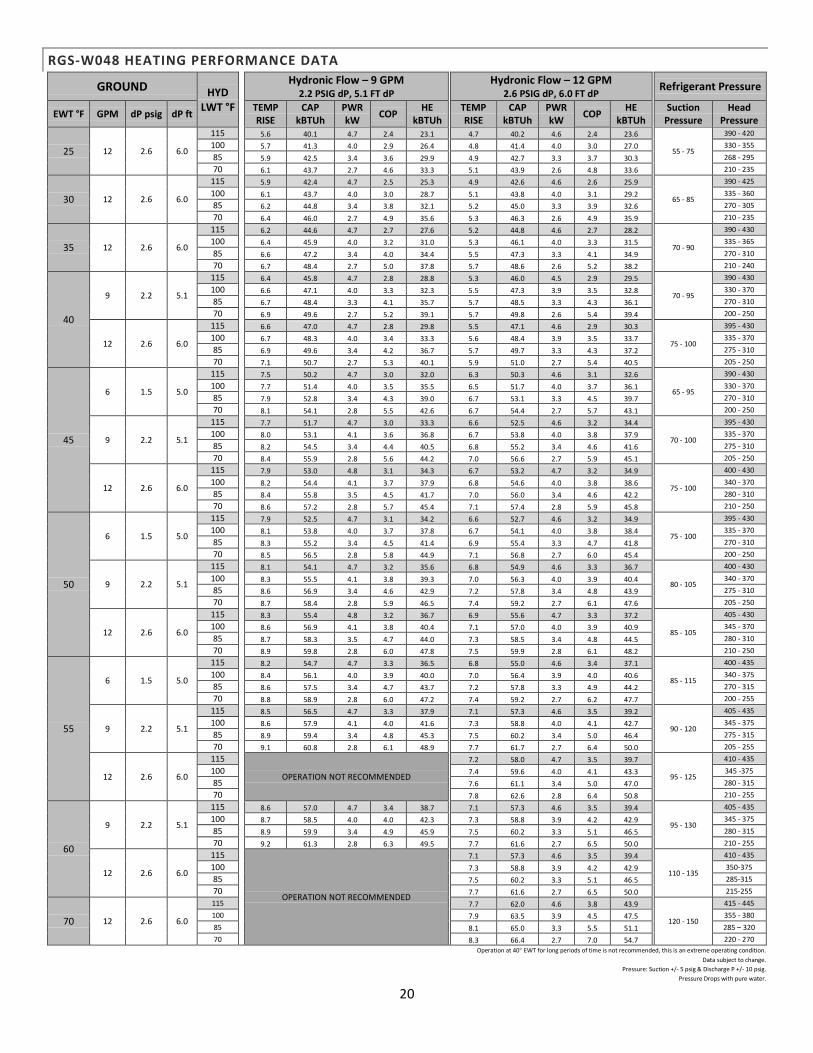
RGS-W048 HEATING PERFORMANCE DATA
GROUND HYD LWT °F
Hydronic Flow – 9 GPM 2.2 PSIG dP, 5.1 FT dP
Hydronic Flow – 12 GPM 2.6 PSIG dP, 6.0 FT dP
Refrigerant Pressure
EWT °F GPM dP psig dP ft TEMP RISE
CAP kBTUh
PWR kW
COP HE
kBTUh
TEMP RISE
CAP kBTUh
PWR kW
COP HE
kBTUh
Suction Pressure
Head Pressure
25 12 2.6 6.0
115 5.6 40.1 4.7 2.4 23.1 4.7 40.2 4.6 2.4 23.6
55 - 75
390 - 420
100 5.7 41.3 4.0 2.9 26.4 4.8 41.4 4.0 3.0 27.0 330 - 355
85 5.9 42.5 3.4 3.6 29.9 4.9 42.7 3.3 3.7 30.3 268 - 295
70 6.1 43.7 2.7 4.6 33.3 5.1 43.9 2.6 4.8 33.6 210 - 235
30 12 2.6 6.0
115 5.9 42.4 4.7 2.5 25.3 4.9 42.6 4.6 2.6 25.9
65 - 85
390 - 425
100 6.1 43.7 4.0 3.0 28.7 5.1 43.8 4.0 3.1 29.2 335 - 360
85 6.2 44.8 3.4 3.8 32.1 5.2 45.0 3.3 3.9 32.6 270 - 305
70 6.4 46.0 2.7 4.9 35.6 5.3 46.3 2.6 4.9 35.9 210 - 235
35 12 2.6 6.0
115 6.2 44.6 4.7 2.7 27.6 5.2 44.8 4.6 2.7 28.2
70 - 90
390 - 430
100 6.4 45.9 4.0 3.2 31.0 5.3 46.1 4.0 3.3 31.5 335 - 365
85 6.6 47.2 3.4 4.0 34.4 5.5 47.3 3.3 4.1 34.9 270 - 310
70 6.7 48.4 2.7 5.0 37.8 5.7 48.6 2.6 5.2 38.2 210 - 240
40
9 2.2 5.1
115 6.4 45.8 4.7 2.8 28.8 5.3 46.0 4.5 2.9 29.5
70 - 95
390 - 430
100 6.6 47.1 4.0 3.3 32.3 5.5 47.3 3.9 3.5 32.8 330 - 370
85 6.7 48.4 3.3 4.1 35.7 5.7 48.5 3.3 4.3 36.1 270 - 310
70 6.9 49.6 2.7 5.2 39.1 5.7 49.8 2.6 5.4 39.4 200 - 250
12 2.6 6.0
115 6.6 47.0 4.7 2.8 29.8 5.5 47.1 4.6 2.9 30.3
75 - 100
395 - 430
100 6.7 48.3 4.0 3.4 33.3 5.6 48.4 3.9 3.5 33.7 335 - 370
85 6.9 49.6 3.4 4.2 36.7 5.7 49.7 3.3 4.3 37.2 275 - 310
70 7.1 50.7 2.7 5.3 40.1 5.9 51.0 2.7 5.4 40.5 205 - 250
45
6 1.5 5.0
115 7.5 50.2 4.7 3.0 32.0 6.3 50.3 4.6 3.1 32.6
65 - 95
390 - 430
100 7.7 51.4 4.0 3.5 35.5 6.5 51.7 4.0 3.7 36.1 330 - 370
85 7.9 52.8 3.4 4.3 39.0 6.7 53.1 3.3 4.5 39.7 270 - 310
70 8.1 54.1 2.8 5.5 42.6 6.7 54.4 2.7 5.7 43.1 200 - 250
9 2.2 5.1
115 7.7 51.7 4.7 3.0 33.3 6.6 52.5 4.6 3.2 34.4
70 - 100
395 - 430
100 8.0 53.1 4.1 3.6 36.8 6.7 53.8 4.0 3.8 37.9 335 - 370
85 8.2 54.5 3.4 4.4 40.5 6.8 55.2 3.4 4.6 41.6 275 - 310
70 8.4 55.9 2.8 5.6 44.2 7.0 56.6 2.7 5.9 45.1 205 - 250
12 2.6 6.0
115 7.9 53.0 4.8 3.1 34.3 6.7 53.2 4.7 3.2 34.9
75 - 100
400 - 430
100 8.2 54.4 4.1 3.7 37.9 6.8 54.6 4.0 3.8 38.6 340 - 370
85 8.4 55.8 3.5 4.5 41.7 7.0 56.0 3.4 4.6 42.2 280 - 310
70 8.6 57.2 2.8 5.7 45.4 7.1 57.4 2.8 5.9 45.8 210 - 250
50
6 1.5 5.0
115 7.9 52.5 4.7 3.1 34.2 6.6 52.7 4.6 3.2 34.9
75 - 100
395 - 430
100 8.1 53.8 4.0 3.7 37.8 6.7 54.1 4.0 3.8 38.4 335 - 370
85 8.3 55.2 3.4 4.5 41.4 6.9 55.4 3.3 4.7 41.8 270 - 310
70 8.5 56.5 2.8 5.8 44.9 7.1 56.8 2.7 6.0 45.4 200 - 250
9 2.2 5.1
115 8.1 54.1 4.7 3.2 35.6 6.8 54.9 4.6 3.3 36.7
80 - 105
400 - 430
100 8.3 55.5 4.1 3.8 39.3 7.0 56.3 4.0 3.9 40.4 340 - 370
85 8.6 56.9 3.4 4.6 42.9 7.2 57.8 3.4 4.8 43.9 275 - 310
70 8.7 58.4 2.8 5.9 46.5 7.4 59.2 2.7 6.1 47.6 205 - 250
12 2.6 6.0
115 8.3 55.4 4.8 3.2 36.7 6.9 55.6 4.7 3.3 37.2
85 - 105
405 - 430
100 8.6 56.9 4.1 3.8 40.4 7.1 57.0 4.0 3.9 40.9 345 - 370
85 8.7 58.3 3.5 4.7 44.0 7.3 58.5 3.4 4.8 44.5 280 - 310
70 8.9 59.8 2.8 6.0 47.8 7.5 59.9 2.8 6.1 48.2 210 - 250
55
6 1.5 5.0
115 8.2 54.7 4.7 3.3 36.5 6.8 55.0 4.6 3.4 37.1
85 - 115
400 - 435
100 8.4 56.1 4.0 3.9 40.0 7.0 56.4 3.9 4.0 40.6 340 - 375
85 8.6 57.5 3.4 4.7 43.7 7.2 57.8 3.3 4.9 44.2 270 - 315
70 8.8 58.9 2.8 6.0 47.2 7.4 59.2 2.7 6.2 47.7 200 - 255
9 2.2 5.1
115 8.5 56.5 4.7 3.3 37.9 7.1 57.3 4.6 3.5 39.2
90 - 120
405 - 435
100 8.6 57.9 4.1 4.0 41.6 7.3 58.8 4.0 4.1 42.7 345 - 375
85 8.9 59.4 3.4 4.8 45.3 7.5 60.2 3.4 5.0 46.4 275 - 315
70 9.1 60.8 2.8 6.1 48.9 7.7 61.7 2.7 6.4 50.0 205 - 255
12 2.6 6.0
115
OPERATION NOT RECOMMENDED
7.2 58.0 4.7 3.5 39.7
95 - 125
410 - 435
100 7.4 59.6 4.0 4.1 43.3 345 -375
85 7.6 61.1 3.4 5.0 47.0 280 - 315
70 7.8 62.6 2.8 6.4 50.8 210 - 255
60
9 2.2 5.1
115 8.6 57.0 4.7 3.4 38.7 7.1 57.3 4.6 3.5 39.4
95 - 130
405 - 435
100 8.7 58.5 4.0 4.0 42.3 7.3 58.8 3.9 4.2 42.9 345 - 375
85 8.9 59.9 3.4 4.9 45.9 7.5 60.2 3.3 5.1 46.5 280 - 315
70 9.2 61.3 2.8 6.3 49.5 7.7 61.6 2.7 6.5 50.0 210 - 255
12 2.6 6.0
115
OPERATION NOT RECOMMENDED
7.1 57.3 4.6 3.5 39.4
110 - 135
410 - 435
100 7.3 58.8 3.9 4.2 42.9 350-375
85 7.5 60.2 3.3 5.1 46.5 285-315
70 7.7 61.6 2.7 6.5 50.0 215-255
70 12 2.6 6.0
115 7.7 62.0 4.6 3.8 43.9
120 - 150
415 - 445
100 7.9 63.5 3.9 4.5 47.5 355 - 380
85 8.1 65.0 3.3 5.5 51.1 285 – 320
70 8.3 66.4 2.7 7.0 54.7 220 - 270
Operation at 40° EWT for long periods of time is not recommended, this is an extreme operating condition.
Data subject to change.
Pressure: Suction +/- 5 psig & Discharge P +/- 10 psig.
Pressure Drops with pure water.

21
RGS-W048 COOLING PERFORMANCE DATA
GROUND HYD LWT °F
Hydronic Flow – 9 GPM 2.2 PSIG dP, 5.1 FT dP
Hydronic Flow – 12 GPM 2.6 PSIG dP, 6.0 FT dP
Refrigerant Pressure
EWT °F
GPM dP psig dP ft TEMP RISE
CAP kBTUh
PWR kW
EER HR
kBTUh
TEMP RISE
CAP kBTUh
PWR kW
EER HR
kBTUh
Suction Pressure
Head Pressure
50
6 1.5 5.0
35 10.6 41.7 2.1 19.4 51.9 9.2 43.3 2.1 20.0 53.7
220 - 260
80 - 100
40 11.6 45.5 2.1 21.1 55.9 10.1 47.4 2.1 21.7 58.0 85 - 105 45 12.6 49.4 2.1 22.7 60.0 10.9 51.5 2.2 23.3 62.3 90 - 110 50 13.6 53.4 2.2 24.3 64.2 11.8 55.6 2.2 25.1 66.6 95 - 115
9 2.2 5.1
35 10.8 42.2 2.0 20.3 52.1 9.4 44.0 2.1 21.0 54.1
210 - 250
80 - 100
40 11.8 46.2 2.1 22.0 56.4 10.2 48.1 2.1 22.7 58.4 85 - 105 45 12.7 50.1 2.1 23.8 60.5 11.1 52.1 2.1 24.4 62.8 90 - 110 50 13.7 54.0 2.1 25.4 64.6 11.9 56.2 2.1 26.1 67.0 95 - 115
12 2.6 6.0
35 10.9 42.8 2.0 21.2 52.6 9.4 44.4 2.0 21.9 54.3
200 - 240
85 - 100
40 11.9 46.8 2.0 22.9 56.8 10.4 48.6 2.0 23.8 58.7 90 - 105 45 12.9 50.7 2.0 24.6 61.0 11.2 52.7 2.0 25.5 63.1 95 - 110 50 14.0 54.8 2.0 26.4 65.2 12.0 56.9 2.0 27.3 67.5 100 - 115
60
6 1.5 5.0
35 10.4 40.9 2.4 16.8 52.2 9.1 42.6 2.4 17.3 54.1
75 - 100
395 - 430
40 11.3 44.6 2.4 18.1 56.1 9.8 46.4 2.4 18.7 58.1 335 - 370
45 12.3 48.2 2.4 19.4 59.9 10.6 50.2 2.5 20.1 62.1 270 - 310
50 13.2 51.8 2.5 20.7 63.8 11.5 54.0 2.5 21.4 66.1 200 - 250
9 2.2 5.1
35 10.5 41.5 2.3 17.6 52.4 9.1 43.2 2.3 18.1 54.3
80 - 105
400 - 430
40 11.5 45.2 2.3 19.0 56.4 9.9 47.0 2.4 19.5 58.4 340 - 370
45 12.5 48.8 2.4 20.3 60.4 10.8 50.8 2.4 21.0 62.6 275 - 310
50 13.4 52.6 2.4 21.7 64.3 11.6 54.7 2.4 22.4 66.6 205 - 250
12 2.6 6.0
35 10.6 42.0 2.3 18.3 52.8 9.2 43.7 2.3 18.9 54.5
85 - 105
405 - 430
40 11.6 45.8 2.3 19.8 56.8 10.1 47.5 2.3 20.4 58.7 345 - 370
45 12.6 49.5 2.3 21.2 60.8 10.9 51.5 2.3 21.9 62.8 280 - 310
50 13.6 53.2 2.3 22.6 64.7 11.8 55.3 2.3 23.3 66.9 210 - 250
65
6 1.5 5.0
35 10.4 40.6 2.5 15.7 52.3 9.0 42.2 2.6 16.2 54.2
275 - 315
85 - 105
40 11.2 44.1 2.6 17.0 56.1 9.8 45.9 2.6 17.4 58.1 90 - 110 45 12.2 47.6 2.6 18.1 59.9 10.5 49.6 2.6 18.7 62.1 95 - 120 50 13.0 51.2 2.6 19.3 63.7 11.3 53.2 2.6 19.9 66.0 95 - 120
9 2.2 5.1
35 10.5 41.1 2.5 16.4 52.6 9.1 42.8 2.5 17.0 54.5
265 - 305
85 - 105
40 11.3 44.7 2.5 17.7 56.5 9.8 46.5 2.5 18.3 58.4 90 - 110 45 12.3 48.3 2.5 18.9 60.3 10.6 50.3 2.5 19.5 62.4 95 - 120 50 13.2 51.8 2.5 20.2 64.1 11.5 53.9 2.5 20.7 66.4 100 - 120
12 2.6 6.0
35 10.6 41.7 2.4 17.1 52.9 9.2 43.2 2.4 17.7 54.6
255 - 295
90 - 105
40 11.5 45.2 2.4 18.4 56.8 9.9 47.1 2.4 19.0 58.7 95 - 110
45 12.5 48.8 2.4 19.7 60.7 10.8 50.8 2.4 20.4 62.7 100 - 120
50 13.3 52.5 2.5 21.0 64.5 11.6 54.6 2.5 21.7 66.7 100 - 120
70
6 1.5 5.0 OPERATION NOT RECOMMEDED
9 2.2 5.1
35 6.4 40.7 2.6 14.9 50.0 9.0 42.4 2.6 15.3 51.8
280 - 325
85 - 105
40 7.0 44.2 2.6 15.9 53.5 9.8 46.0 2.6 16.4 55.4 90 - 110 45 7.6 47.6 2.6 17.1 57.0 10.5 49.6 2.7 17.6 59.1 95 - 120 50 8.1 51.0 2.7 18.1 60.5 11.3 53.1 2.7 18.6 62.7 100 - 125
12 2.6 6.0
35 6.6 41.3 2.5 15.4 50.2 9.1 42.9 2.5 15.9 51.9
270 - 315
90 - 105
40 7.1 44.8 2.6 16.5 53.8 9.8 46.5 2.6 17.2 55.6 95 - 110
45 7.7 48.3 2.6 17.7 57.4 10.6 50.2 2.6 18.3 59.3 100 - 120
50 8.3 51.8 2.6 18.8 60.9 11.3 53.8 2.6 19.4 63.0 100 - 125
80
6 1.5 5.0 OPERATION NOT RECOMMEDED
9 2.2 5.1
35 6.3 39.9 2.9 13.1 50.2 8.8 41.6 2.9 13.5 52.0
315 - 365
85 - 105
40 6.9 43.2 2.9 14.0 53.6 9.5 45.0 2.9 14.5 55.5 90 - 110 45 7.4 46.4 2.9 15.0 56.9 10.2 48.3 3.0 15.4 58.9 95 - 115 50 7.8 49.6 3.0 15.9 60.2 10.9 51.7 3.0 16.3 62.2 100 - 120
12 2.6 6.0
35 6.4 40.5 2.8 13.6 50.6 9.0 42.1 2.8 14.1 52.2
305 - 355
90 - 105
40 7.0 43.8 2.8 14.7 53.8 9.7 45.4 2.8 15.2 55.6 95 - 110
45 7.4 47.0 2.9 15.6 57.2 10.4 48.8 2.9 16.1 59.1 100 - 120
50 8.0 50.3 2.9 16.5 60.5 11.1 52.3 2.9 17.1 62.6 105 - 125
90
6 1.5 5.0 OPERATION NOT RECOMMEDED
9 2.2 5.1
12 2.6 6.0
35 10.1 39.7 3.1 12.3 50.8 8.8 41.3 3.1 12.7 52.4
340 - 390
90 - 105
40 10.9 42.8 3.1 13.0 54.0 9.4 44.4 3.1 13.5 55.6 95 - 110
45 11.6 45.8 3.1 13.8 57.0 10.1 47.5 3.1 14.2 58.9 105 -115
50 12.5 48.7 3.2 14.6 60.1 10.8 50.7 3.2 15.1 62.0 110 - 130
100
6 1.5 5.0 OPERATION NOT RECOMMEDED
9 2.2 5.1
12 2.6 6.0
35 9.9 38.9 3.3 11.0 51.0 8.5 40.5 3.4 11.4 52.6
370 - 430
95 - 110
40 10.6 41.8 3.4 11.6 54.0 9.2 43.3 3.4 12.1 55.6 100 - 115
45 11.3 44.6 3.4 12.4 56.8 9.8 46.3 3.4 12.8 58.5 105 - 125
50 12.0 47.3 3.4 13.0 59.7 10.4 49.2 3.5 13.4 61.6 110 - 130
Operation at 40° EWT in cooling for long periods of time is not recommended, this is an extreme operating condition.
Pressure: Suction +/- 5 psig & Discharge P +/- 10 psig.
Pressure Drops with pure water.
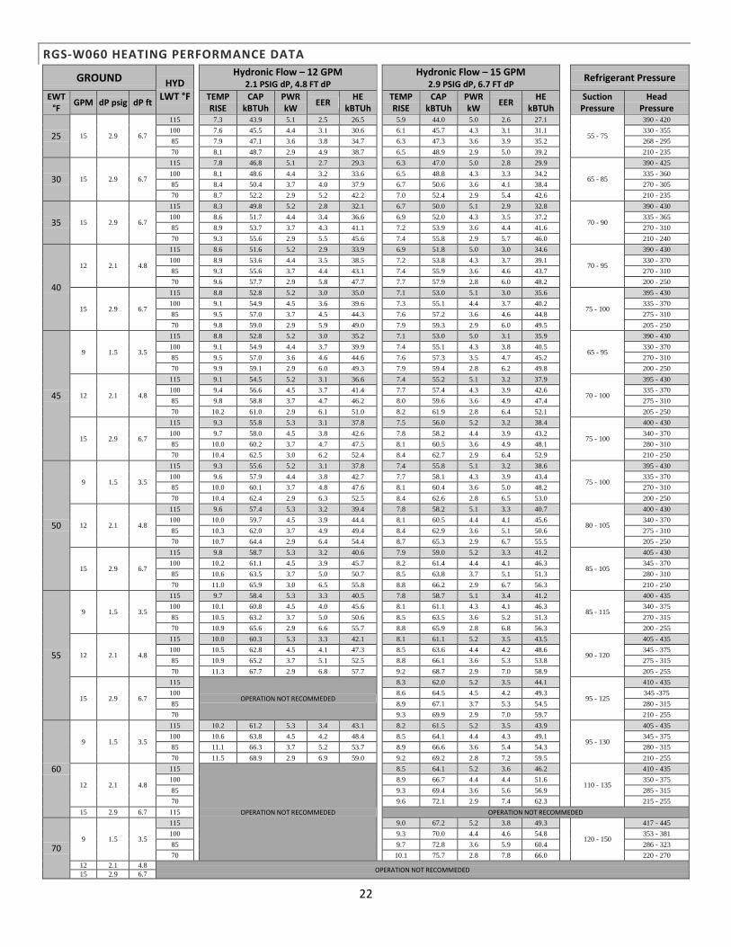
22
RGS-W060 HEATING PERFORMANCE DATA
GROUND HYD LWT °F
Hydronic Flow – 12 GPM 2.1 PSIG dP, 4.8 FT dP
Hydronic Flow – 15 GPM 2.9 PSIG dP, 6.7 FT dP
Refrigerant Pressure
EWT °F
GPM dP psig dP ft TEMP RISE
CAP kBTUh
PWR kW
EER HE
kBTUh
TEMP RISE
CAP kBTUh
PWR kW
EER HE
kBTUh
Suction Pressure
Head Pressure
25 15 2.9 6.7
115 7.3 43.9 5.1 2.5 26.5 5.9 44.0 5.0 2.6 27.1
55 - 75
390 - 420
100 7.6 45.5 4.4 3.1 30.6 6.1 45.7 4.3 3.1 31.1 330 - 355
85 7.9 47.1 3.6 3.8 34.7 6.3 47.3 3.6 3.9 35.2 268 - 295
70 8.1 48.7 2.9 4.9 38.7 6.5 48.9 2.9 5.0 39.2 210 - 235
30 15 2.9 6.7
115 7.8 46.8 5.1 2.7 29.3 6.3 47.0 5.0 2.8 29.9
65 - 85
390 - 425
100 8.1 48.6 4.4 3.2 33.6 6.5 48.8 4.3 3.3 34.2 335 - 360
85 8.4 50.4 3.7 4.0 37.9 6.7 50.6 3.6 4.1 38.4 270 - 305
70 8.7 52.2 2.9 5.2 42.2 7.0 52.4 2.9 5.4 42.6 210 - 235
35 15 2.9 6.7
115 8.3 49.8 5.2 2.8 32.1 6.7 50.0 5.1 2.9 32.8
70 - 90
390 - 430
100 8.6 51.7 4.4 3.4 36.6 6.9 52.0 4.3 3.5 37.2 335 - 365
85 8.9 53.7 3.7 4.3 41.1 7.2 53.9 3.6 4.4 41.6 270 - 310
70 9.3 55.6 2.9 5.5 45.6 7.4 55.8 2.9 5.7 46.0 210 - 240
40
12 2.1 4.8
115 8.6 51.6 5.2 2.9 33.9 6.9 51.8 5.0 3.0 34.6
70 - 95
390 - 430
100 8.9 53.6 4.4 3.5 38.5 7.2 53.8 4.3 3.7 39.1 330 - 370
85 9.3 55.6 3.7 4.4 43.1 7.4 55.9 3.6 4.6 43.7 270 - 310
70 9.6 57.7 2.9 5.8 47.7 7.7 57.9 2.8 6.0 48.2 200 - 250
15 2.9 6.7
115 8.8 52.8 5.2 3.0 35.0 7.1 53.0 5.1 3.0 35.6
75 - 100
395 - 430
100 9.1 54.9 4.5 3.6 39.6 7.3 55.1 4.4 3.7 40.2 335 - 370
85 9.5 57.0 3.7 4.5 44.3 7.6 57.2 3.6 4.6 44.8 275 - 310
70 9.8 59.0 2.9 5.9 49.0 7.9 59.3 2.9 6.0 49.5 205 - 250
45
9 1.5 3.5
115 8.8 52.8 5.2 3.0 35.2 7.1 53.0 5.0 3.1 35.9
65 - 95
390 - 430
100 9.1 54.9 4.4 3.7 39.9 7.4 55.1 4.3 3.8 40.5 330 - 370
85 9.5 57.0 3.6 4.6 44.6 7.6 57.3 3.5 4.7 45.2 270 - 310
70 9.9 59.1 2.9 6.0 49.3 7.9 59.4 2.8 6.2 49.8 200 - 250
12 2.1 4.8
115 9.1 54.5 5.2 3.1 36.6 7.4 55.2 5.1 3.2 37.9
70 - 100
395 - 430
100 9.4 56.6 4.5 3.7 41.4 7.7 57.4 4.3 3.9 42.6 335 - 370
85 9.8 58.8 3.7 4.7 46.2 8.0 59.6 3.6 4.9 47.4 275 - 310
70 10.2 61.0 2.9 6.1 51.0 8.2 61.9 2.8 6.4 52.1 205 - 250
15 2.9 6.7
115 9.3 55.8 5.3 3.1 37.8 7.5 56.0 5.2 3.2 38.4
75 - 100
400 - 430
100 9.7 58.0 4.5 3.8 42.6 7.8 58.2 4.4 3.9 43.2 340 - 370
85 10.0 60.2 3.7 4.7 47.5 8.1 60.5 3.6 4.9 48.1 280 - 310
70 10.4 62.5 3.0 6.2 52.4 8.4 62.7 2.9 6.4 52.9 210 - 250
50
9 1.5 3.5
115 9.3 55.6 5.2 3.1 37.8 7.4 55.8 5.1 3.2 38.6
75 - 100
395 - 430
100 9.6 57.9 4.4 3.8 42.7 7.7 58.1 4.3 3.9 43.4 335 - 370
85 10.0 60.1 3.7 4.8 47.6 8.1 60.4 3.6 5.0 48.2 270 - 310
70 10.4 62.4 2.9 6.3 52.5 8.4 62.6 2.8 6.5 53.0 200 - 250
12 2.1 4.8
115 9.6 57.4 5.3 3.2 39.4 7.8 58.2 5.1 3.3 40.7
80 - 105
400 - 430
100 10.0 59.7 4.5 3.9 44.4 8.1 60.5 4.4 4.1 45.6 340 - 370
85 10.3 62.0 3.7 4.9 49.4 8.4 62.9 3.6 5.1 50.6 275 - 310
70 10.7 64.4 2.9 6.4 54.4 8.7 65.3 2.9 6.7 55.5 205 - 250
15 2.9 6.7
115 9.8 58.7 5.3 3.2 40.6 7.9 59.0 5.2 3.3 41.2
85 - 105
405 - 430
100 10.2 61.1 4.5 3.9 45.7 8.2 61.4 4.4 4.1 46.3 345 - 370
85 10.6 63.5 3.7 5.0 50.7 8.5 63.8 3.7 5.1 51.3 280 - 310
70 11.0 65.9 3.0 6.5 55.8 8.8 66.2 2.9 6.7 56.3 210 - 250
55
9 1.5 3.5
115 9.7 58.4 5.3 3.3 40.5 7.8 58.7 5.1 3.4 41.2
85 - 115
400 - 435
100 10.1 60.8 4.5 4.0 45.6 8.1 61.1 4.3 4.1 46.3 340 - 375
85 10.5 63.2 3.7 5.0 50.6 8.5 63.5 3.6 5.2 51.3 270 - 315
70 10.9 65.6 2.9 6.6 55.7 8.8 65.9 2.8 6.8 56.3 200 - 255
12 2.1 4.8
115 10.0 60.3 5.3 3.3 42.1 8.1 61.1 5.2 3.5 43.5
90 - 120
405 - 435
100 10.5 62.8 4.5 4.1 47.3 8.5 63.6 4.4 4.2 48.6 345 - 375
85 10.9 65.2 3.7 5.1 52.5 8.8 66.1 3.6 5.3 53.8 275 - 315
70 11.3 67.7 2.9 6.8 57.7 9.2 68.7 2.9 7.0 58.9 205 - 255
15 2.9 6.7
115
OPERATION NOT RECOMMEDED
8.3 62.0 5.2 3.5 44.1
95 - 125
410 - 435
100 8.6 64.5 4.5 4.2 49.3 345 -375
85 8.9 67.1 3.7 5.3 54.5 280 - 315
70 9.3 69.9 2.9 7.0 59.7 210 - 255
60
9 1.5 3.5
115 10.2 61.2 5.3 3.4 43.1 8.2 61.5 5.2 3.5 43.9
95 - 130
405 - 435
100 10.6 63.8 4.5 4.2 48.4 8.5 64.1 4.4 4.3 49.1 345 - 375
85 11.1 66.3 3.7 5.2 53.7 8.9 66.6 3.6 5.4 54.3 280 - 315
70 11.5 68.9 2.9 6.9 59.0 9.2 69.2 2.8 7.2 59.5 210 - 255
12 2.1 4.8
115
OPERATION NOT RECOMMEDED
8.5 64.1 5.2 3.6 46.2
110 - 135
410 - 435
100 8.9 66.7 4.4 4.4 51.6 350 - 375
85 9.3 69.4 3.6 5.6 56.9 285 - 315
70 9.6 72.1 2.9 7.4 62.3 215 - 255
15 2.9 6.7 115 OPERATION NOT RECOMMEDED
70 9 1.5 3.5
115 9.0 67.2 5.2 3.8 49.3
120 - 150
417 - 445
100 9.3 70.0 4.4 4.6 54.8 353 - 381
85 9.7 72.8 3.6 5.9 60.4 286 - 323
70 10.1 75.7 2.8 7.8 66.0 220 - 270
12 2.1 4.8 OPERATION NOT RECOMMEDED
15 2.9 6.7
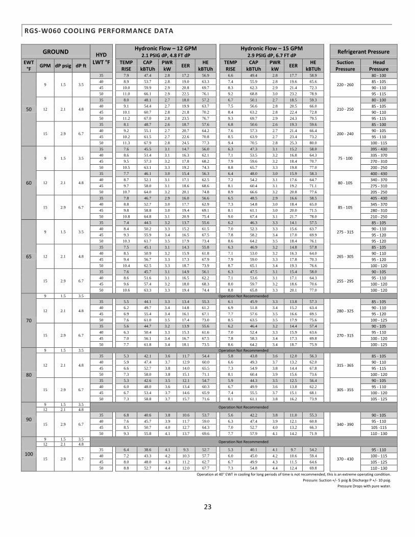
23
RGS-W060 COOLING PERFORMANCE DATA
GROUND HYD LWT °F
Hydronic Flow – 12 GPM 2.1 PSIG dP, 4.8 FT dP
Hydronic Flow – 15 GPM 2.9 PSIG dP, 6.7 FT dP
Refrigerant Pressure
EWT °F
GPM dP psig dP ft TEMP RISE
CAP kBTUh
PWR kW
EER HE
kBTUh
TEMP RISE
CAP kBTUh
PWR kW
EER HE
kBTUh
Suction Pressure
Head Pressure
50
9 1.5 3.5
35 7.9 47.4 2.8 17.2 56.9 6.6 49.4 2.8 17.7 58.9
220 - 260
80 - 100
40 8.9 53.7 2.8 19.0 63.3 7.4 55.9 2.8 19.6 65.6 85 - 105
45 10.0 59.9 2.9 20.8 69.7 8.3 62.3 2.9 21.4 72.3 90 - 110
50 11.0 66.1 2.9 22.5 76.1 9.2 68.8 3.0 23.2 78.9 95 - 115
12 2.1 4.8
35 8.0 48.1 2.7 18.0 57.2 6.7 50.1 2.7 18.5 59.3
210 - 250
80 - 100
40 9.1 54.4 2.7 19.9 63.7 7.5 56.6 2.8 20.5 66.0 85 - 105
45 10.1 60.7 2.8 21.8 70.2 8.4 63.2 2.8 22.4 72.8 90 - 110
50 11.2 67.0 2.8 23.5 76.7 9.3 69.7 2.9 24.3 79.5 95 - 115
15 2.9 6.7
35 8.1 48.7 2.6 18.7 57.6 6.8 50.6 2.6 19.3 59.6
200 - 240
85 - 100
40 9.2 55.1 2.7 20.7 64.2 7.6 57.3 2.7 21.4 66.4 90 - 105
45 10.2 61.5 2.7 22.6 70.8 8.5 63.9 2.7 23.4 73.2 95 - 110
50 11.3 67.9 2.8 24.5 77.3 9.4 70.5 2.8 25.3 80.0 100 - 115
60
9 1.5 3.5
35 7.6 45.5 3.1 14.7 56.0 6.3 47.3 3.1 15.2 58.0
75 - 100
395 - 430
40 8.6 51.4 3.1 16.3 62.1 7.1 53.5 3.2 16.8 64.3 335 - 370
45 9.5 57.3 3.2 17.8 68.2 7.9 59.6 3.2 18.4 70.7 270 - 310
50 10.5 63.1 3.3 19.2 74.3 8.8 65.7 3.3 19.8 77.0 200 - 250
12 2.1 4.8
35 7.7 46.1 3.0 15.4 56.3 6.4 48.0 3.0 15.9 58.3
80 - 105
400 - 430
40 8.7 52.1 3.1 17.1 62.5 7.2 54.2 3.1 17.6 64.7 340 - 370
45 9.7 58.0 3.1 18.6 68.6 8.1 60.4 3.1 19.2 71.1 275 - 310
50 10.7 64.0 3.2 20.1 74.8 8.9 66.6 3.2 20.8 77.6 205 - 250
15 2.9 6.7
35 7.8 46.7 2.9 16.0 56.6 6.5 48.5 2.9 16.6 58.5
85 - 105
405 - 430
40 8.8 52.7 3.0 17.7 62.9 7.3 54.8 3.0 18.4 65.0 345 - 370
45 9.8 58.8 3.0 19.4 69.1 8.1 61.1 3.0 20.0 71.5 280 - 310
50 10.8 64.8 3.1 20.9 75.4 9.0 67.4 3.1 21.7 78.0 210 - 250
65
9 1.5 3.5
35 7.4 44.5 3.2 13.7 55.6 6.2 46.3 3.3 14.1 57.5
275 - 315
85 - 105
40 8.4 50.2 3.3 15.2 61.5 7.0 52.3 3.3 15.6 63.7 90 - 110
45 9.3 55.9 3.4 16.5 67.5 7.8 58.2 3.4 17.0 69.9 95 - 120
50 10.3 61.7 3.5 17.9 73.4 8.6 64.2 3.5 18.4 76.1 95 - 120
12 2.1 4.8
35 7.5 45.1 3.1 14.3 55.8 6.3 46.9 3.2 14.8 57.8
265 - 305
85 - 105
40 8.5 50.9 3.2 15.9 61.8 7.1 53.0 3.2 16.3 64.0 90 - 110
45 9.4 56.7 3.3 17.3 67.9 7.9 59.0 3.3 17.8 70.3 95 - 120
50 10.4 62.5 3.3 18.7 73.9 8.7 65.1 3.4 19.3 76.6 100 - 120
15 2.9 6.7
35 7.6 45.7 3.1 14.9 56.1 6.3 47.5 3.1 15.4 58.0
255 - 295
90 - 105
40 8.6 51.6 3.1 16.5 62.2 7.1 53.6 3.1 17.1 64.3 95 - 110
45 9.6 57.4 3.2 18.0 68.3 8.0 59.7 3.2 18.6 70.6 100 - 120
50 10.6 63.3 3.3 19.4 74.4 8.8 65.8 3.3 20.1 77.0 100 - 120
70
9 1.5 3.5 Operation Not Recommended
12 2.1 4.8
35 5.5 44.1 3.3 13.4 55.3 6.1 45.9 3.3 13.8 57.3
280 - 325
85 - 105
40 6.2 49.7 3.4 14.8 61.2 6.9 51.8 3.4 15.2 63.4 90 - 110
45 6.9 55.4 3.4 16.1 67.1 7.7 57.6 3.5 16.6 69.5 95 - 120
50 7.6 61.0 3.5 17.4 73.0 8.5 63.5 3.5 17.9 75.6 100 - 125
15 2.9 6.7
35 5.6 44.7 3.2 13.9 55.6 6.2 46.4 3.2 14.4 57.4
270 - 315
90 - 105
40 6.3 50.4 3.3 15.3 61.6 7.0 52.4 3.3 15.9 63.6 95 - 110
45 7.0 56.1 3.4 16.7 67.5 7.8 58.3 3.4 17.3 69.8 100 - 120
50 7.7 61.8 3.4 18.1 73.5 8.6 64.2 3.4 18.7 75.9 100 - 125
80
9 1.5 3.5 Operation Not Recommended
12 2.1 4.8
35 5.3 42.1 3.6 11.7 54.4 5.8 43.8 3.6 12.0 56.3
315 - 365
85 - 105
40 5.9 47.4 3.7 12.9 60.0 6.6 49.3 3.7 13.2 62.0 90 - 110
45 6.6 52.7 3.8 14.0 65.5 7.3 54.9 3.8 14.4 67.8 95 - 115
50 7.3 58.0 3.8 15.1 71.1 8.1 60.4 3.9 15.6 73.6 100 - 120
15 2.9 6.7
35 5.3 42.6 3.5 12.1 54.7 5.9 44.3 3.5 12.5 56.4
305 - 355
90 - 105
40 6.0 48.0 3.6 13.4 60.3 6.7 49.9 3.6 13.8 62.2 95 - 110
45 6.7 53.4 3.7 14.6 65.9 7.4 55.5 3.7 15.1 68.1 100 - 120
50 7.3 58.8 3.7 15.7 71.6 8.1 61.1 3.8 16.2 73.9 105 - 125
90
9 1.5 3.5 Operation Not Recommended
12 2.1 4.8
15 2.9 6.7
35 6.8 40.6 3.8 10.6 53.7 5.6 42.2 3.8 11.0 55.3
340 - 390
90 - 105
40 7.6 45.7 3.9 11.7 59.0 6.3 47.4 3.9 12.1 60.8 95 - 110
45 8.5 50.7 4.0 12.7 64.3 7.0 52.7 4.0 13.2 66.3 105 -115
50 9.3 55.8 4.1 13.7 69.6 7.7 57.9 4.1 14.2 71.9 110 - 130
100
9 1.5 3.5 Operation Not Recommended
12 2.1 4.8
15 2.9 6.7
35 6.4 38.6 4.1 9.3 52.7 5.3 40.1 4.1 9.7 54.2
370 - 430
95 - 110
40 7.2 43.3 4.2 10.3 57.7 6.0 45.0 4.2 10.6 59.4 100 - 115
45 8.0 48.0 4.3 11.2 62.7 6.7 49.9 4.3 11.5 64.6 105 - 125
50 8.8 52.7 4.4 12.0 67.7 7.3 54.8 4.4 12.4 69.8 110 - 130
Operation at 40° EWT in cooling for long periods of time is not recommended, this is an extreme operating condition.
Pressure: Suction +/- 5 psig & Discharge P +/- 10 psig.
Pressure Drops with pure water.

24
RGS-W072 HEATING PERFORMANCE DATA
GROUND HYD LWT °F
Hydronic Flow – 15 GPM 3.2 PSIG dP, 7.4 FT dP
Hydronic Flow – 18 GPM 3.7 PSIG dP, 8.5 FT dP
Refrigerant Pressure
EWT °F
GPM dP psig dP ft TEMP RISE
CAP kBTUh
PWR kW
EER HE
kBTUh
TEMP RISE
CAP kBTUh
PWR kW
EER HE
kBTUh
Suction Pressure
Head Pressure
25 18 3.7 8.5
115 5.6 58.6 6.7 2.5 26.3 4.7 58.8 6.6 2.6 26.9
65 - 80
390 - 420
100 5.8 60.2 5.8 3.1 30.2 4.8 60.4 5.5 3.1 30.8 330 - 355
85 6.0 61.7 4.7 3.8 34.3 5.0 61.9 4.6 3.9 34.7 268 - 295
70 6.1 63.2 3.6 5.0 38.2 5.1 63.5 3.6 5.2 38.6 210 - 235
30 18 3.7 8.5
115 6.1 63.5 6.7 2.7 29.9 5.1 63.7 6.6 2.8 30.6
70 - 100
390 - 425
100 6.3 65.3 5.8 3.3 34.0 5.2 65.5 5.7 3.4 34.6 335 - 360
85 6.5 67.0 4.7 4.1 38.1 5.4 67.3 4.6 4.2 38.6 270 - 305
70 6.6 68.8 3.7 5.4 42.2 5.6 69.0 3.6 5.6 42.7 210 - 235
35 18 3.7 8.5
115 6.6 68.3 6.9 2.9 33.6 5.5 68.7 6.6 3.0 34.2
70 - 100
390 - 430
100 6.8 70.4 5.8 3.5 37.8 5.6 70.6 5.7 3.6 38.4 335 - 365
85 6.9 72.3 4.8 4.4 42.1 5.8 72.6 4.7 4.5 42.6 270 - 310
70 7.2 74.3 3.8 5.8 46.3 6.0 74.7 3.7 5.9 46.8 210 - 240
40
15 3.2 7.4
115 6.9 71.5 6.7 3.1 36.1 5.8 71.8 6.6 3.2 36.7
70 - 100
390 - 430
100 7.1 73.6 5.8 3.7 40.3 6.0 74.0 5.7 3.8 41.0 330 - 370
85 7.3 75.8 4.8 4.6 44.7 6.1 76.1 4.7 4.7 45.3 270 - 310
70 7.5 78.1 3.8 6.0 49.0 6.3 78.4 3.7 6.2 49.5 200 - 250
18 3.7 8.5
115 7.0 73.2 6.9 3.1 37.2 5.9 73.5 6.6 3.2 37.8
75 - 100
395 - 430
100 7.3 75.5 5.9 3.7 41.6 6.0 75.8 5.7 3.8 42.2 335 - 370
85 7.5 77.7 4.8 4.6 45.9 6.3 77.9 4.7 4.8 46.4 275 - 310
70 7.7 79.9 3.8 6.1 50.3 6.5 80.2 3.7 6.3 50.8 205 - 250
45
12 2.8 6.5
115 7.1 74.0 6.7 3.2 38.0 6.0 74.2 6.5 3.3 38.8
65 - 95
390 - 430
100 7.4 76.2 5.8 3.8 42.4 6.1 76.6 5.5 4.0 43.1 330 - 370
85 7.6 78.5 4.8 4.7 46.8 6.3 78.8 4.7 4.9 47.4 270 - 310
70 7.8 80.9 3.8 6.2 51.2 6.5 81.2 3.7 6.4 51.7 200 - 250
15 3.2 7.4
115 7.4 76.2 6.9 3.3 39.6 6.2 77.4 6.6 3.4 40.9
70 - 100
395 - 430
100 7.6 78.6 5.8 3.9 44.0 6.4 79.7 5.7 4.1 45.3 335 - 370
85 7.8 81.0 4.8 4.8 48.5 6.6 82.1 4.7 5.0 49.7 275 - 310
70 8.0 83.4 3.8 6.3 53.0 6.8 84.6 3.7 6.6 54.1 205 - 250
18 3.7 8.5
115 7.5 78.2 6.9 3.3 40.8 6.3 78.4 6.7 3.4 41.5
75 - 100
400 - 430
100 7.8 80.5 5.9 4.0 45.3 6.5 80.9 5.8 4.1 45.9 340 - 370
85 8.0 83.0 4.9 4.9 49.9 6.7 83.4 4.8 5.0 50.4 280 - 310
70 8.3 85.4 3.9 6.4 54.3 6.9 85.7 3.8 6.6 54.9 210 - 250
50
12 2.8 6.5
115 7.7 74.0 6.6 3.1 44.7 6.4 74.3 6.4 3.2 45.5
75 - 100
395 - 430
100 8.0 76.4 5.7 3.8 49.5 6.7 76.7 5.6 3.9 50.3 335 - 370
85 8.2 78.8 4.7 4.7 54.4 6.8 79.1 4.6 4.8 55.1 270 - 310
70 8.4 81.1 3.7 6.0 59.2 7.1 81.4 3.6 6.2 59.9 200 - 250
15 3.2 7.4
115 8.0 76.4 6.7 3.1 46.5 6.7 77.4 6.5 3.3 48.0
80 - 105
400 - 430
100 8.2 78.8 5.8 3.8 51.5 6.9 79.9 5.6 4.0 52.9 340 - 370
85 8.5 81.2 4.8 4.8 56.4 7.2 82.4 4.7 5.0 57.8 275 - 310
70 8.7 83.7 3.9 6.1 61.4 7.3 84.8 3.7 6.4 62.7 205 - 250
18 3.7 8.5
115 8.2 78.2 6.7 3.2 47.9 6.8 78.5 6.6 3.3 48.6
85 - 105
405 - 430
100 8.4 80.7 5.8 3.9 53.0 7.0 81.0 5.7 4.0 53.6 345 - 370
85 8.7 83.2 4.8 4.9 57.9 7.2 83.6 4.7 5.0 58.6 280 - 310
70 8.9 85.7 3.9 6.2 63.0 7.5 86.0 3.7 6.4 63.6 210 - 250
55
12 2.8 6.5
115 8.2 78.3 6.6 3.3 48.4 6.8 78.6 6.5 3.4 49.2
85 - 115
400 - 435
100 8.4 80.9 5.7 4.0 53.4 7.1 81.3 5.6 4.1 54.2 340 - 375
85 8.7 83.4 4.8 4.9 58.4 7.2 83.9 4.7 5.0 59.1 270 - 315
70 9.0 86.1 3.9 6.3 63.4 7.5 86.4 3.7 6.5 64.1 200 - 255
15 3.2 7.4
115 8.4 80.9 6.7 3.3 50.4 7.1 82.0 6.5 3.5 51.8
90 - 120
405 - 435
100 8.7 83.6 5.8 4.0 55.4 7.3 84.6 5.7 4.2 56.9 345 - 375
85 9.0 86.1 4.8 5.0 60.5 7.6 87.4 4.7 5.2 61.9 275 - 315
70 9.2 88.8 3.9 6.4 65.6 7.8 90.1 3.7 6.7 67.0 205 - 255
18 3.7 8.5
115
OPERATION NOT RECOMMEDED
6.9 66.1 5.6 3.3 40.8
95 - 125
410 - 435
100 7.2 68.7 4.8 4.0 45.6 345 -375
85 7.4 71.5 4.0 5.0 50.5 280 - 315
70 7.7 74.2 3.1 6.7 55.3 210 - 255
60
12 2.8 6.5
115 8.6 82.7 6.6 3.4 52.1 7.2 83.0 6.5 3.6 53.0
95 - 130
405 - 435
100 8.9 85.5 5.8 4.2 57.2 7.4 85.8 5.6 4.3 58.0 345 - 375
85 9.2 88.2 4.8 5.1 62.4 7.7 88.7 4.7 5.2 63.1 280 - 315
70 9.5 91.0 4.0 6.5 67.5 7.9 91.4 3.9 6.8 68.1 210 - 255
15 3.2 7.4
115
OPERATION NOT RECOMMEDED
7.5 86.5 6.6 3.7 55.7
110 - 135
410 - 435
100 7.7 89.4 5.7 4.4 60.9 350 - 375
85 8.0 92.3 4.8 5.4 66.1 285 - 315
70 8.2 95.2 3.9 7.0 71.4 215 - 255
18 3.7 8.5 115 OPERATION NOT RECOMMEDED
70 12 2.8 6.5
115 8.0 91.8 6.5 3.9 60.4
120 - 150
417 - 445
100 8.2 95.0 5.7 4.7 65.7 353 - 381
85 8.5 98.2 4.8 5.7 71.1 286 - 323
70 8.8 101.3 4.0 7.2 76.5 220 - 270
15 3.2 7.4 OPERATION NOT RECOMMEDED
18 3.7 8.5

25
RGS-W072 COOLING PERFORMANCE DATA
GROUND HYD LWT °F
Hydronic Flow – 15 GPM 3.2 PSIG dP, 6.0 FT dP
Hydronic Flow – 18 GPM 3.78 PSIG dP, 9.5 FT dP
Refrigerant Pressure
EWT °F
GPM dP psig dP ft TEMP RISE
CAP kBTUh
PWR kW
EER HE
kBTUh
TEMP RISE
CAP kBTUh
PWR kW
EER HE
kBTUh
Suction Pressure
Head Pressure
50
12 2.8 6.5
35 9.7 60.6 2.9 18.7 71.0 8.4 63.1 2.9 19.3 73.6
75 - 100
80 - 100
40 10.4 64.9 2.9 19.7 75.4 9.0 67.5 3.0 20.4 78.2 85 - 105
45 11.1 69.2 3.0 20.9 79.8 9.6 72.0 3.0 21.4 82.7 90 - 110
50 11.4 73.4 3.0 21.9 84.2 10.1 76.5 3.1 22.6 87.3 95 - 115
15 3.2 7.4
35 9.8 61.4 2.9 19.6 71.5 8.6 63.9 2.9 20.1 74.1
80 - 105
80 - 100
40 10.5 65.7 2.9 20.7 75.9 9.1 68.4 2.9 21.3 78.8 85 - 105
45 11.2 70.1 2.9 21.8 80.4 9.7 73.0 2.9 22.5 83.4 90 - 110
50 11.9 74.4 2.9 22.8 84.8 10.4 77.4 3.0 23.6 88.0 95 - 115
18 3.7 8.5
35 9.9 62.2 2.8 20.3 72.0 8.7 64.7 2.8 21.0 74.5
85 - 105
85 - 100
40 10.6 66.6 2.9 21.5 76.6 9.2 69.3 2.9 22.3 79.2 90 - 105
45 11.4 71.0 2.9 22.7 81.0 9.8 73.8 2.9 23.4 83.9 95 - 110
50 12.1 75.4 2.9 23.8 85.6 10.5 78.4 2.9 24.6 88.5 100 - 115
60
12 2.8 6.5
35 9.3 58.4 3.4 15.5 70.5 8.1 60.8 3.5 16.0 73.1
275 - 315
395 - 430
40 10.1 63.4 3.5 16.6 75.5 8.8 65.9 3.5 17.1 78.3 335 - 370
45 10.9 68.3 3.5 17.8 80.7 9.5 71.1 3.5 18.2 83.5 270 - 310
50 11.7 73.2 3.5 18.8 85.7 10.1 76.2 3.6 19.4 88.8 200 - 250
15 3.2 7.4
35 9.5 59.2 3.3 16.2 70.9 8.2 61.7 3.4 16.7 73.4
265 - 305
400 - 430
40 10.3 64.2 3.4 17.4 76.0 8.9 66.8 3.4 18.0 78.8 340 - 370
45 11.1 69.2 3.4 18.5 81.1 9.6 72.0 3.4 19.1 84.1 275 - 310
50 11.9 74.2 3.4 19.6 86.3 10.3 77.2 3.5 20.3 89.4 205 - 250
18 3.7 8.5
35 9.6 59.9 3.2 16.8 71.4 8.3 62.3 3.2 17.4 73.8
255 - 295
405 - 430
40 10.4 65.1 3.3 18.0 76.6 9.0 67.5 3.3 18.7 79.1 345 - 370
45 11.2 70.1 3.3 19.3 81.8 9.7 72.9 3.3 19.9 84.6 280 - 310
50 12.0 75.1 3.3 20.5 86.9 10.4 78.1 3.3 21.2 89.9 210 - 250
65
12 2.8 6.5
35 9.1 57.3 3.7 14.2 70.3 8.0 59.7 3.7 14.7 72.8
275 - 315
85 - 105
40 10.0 62.6 3.7 15.3 75.6 8.7 65.2 3.8 15.8 78.4 90 - 110
45 10.8 67.8 3.8 16.5 81.0 9.5 70.6 3.8 17.0 83.9 95 - 120
50 11.7 73.1 3.8 17.6 86.4 10.1 76.1 3.9 18.1 89.5 95 - 120
15 3.2 7.4
35 9.3 58.0 3.6 14.9 70.6 8.1 60.4 3.6 15.3 73.2
265 - 305
85 - 105
40 10.1 63.4 3.6 16.1 76.1 8.8 66.0 3.6 16.5 78.8 90 - 110
45 10.9 68.7 3.6 17.2 81.5 9.6 71.5 3.7 17.8 84.5 95 - 120
50 11.9 74.0 3.7 18.4 86.9 10.3 77.0 3.7 19.0 90.2 100 - 120
18 3.7 8.5
35 9.5 58.8 3.5 15.4 71.1 8.2 61.2 3.5 16.0 73.4
255 - 295
90 - 105
40 10.3 64.2 3.5 16.7 76.6 8.9 66.8 3.5 17.3 79.1 95 - 110
45 11.2 69.6 3.5 18.0 82.1 9.7 72.4 3.6 18.5 84.8 100 - 120
50 12.0 75.1 3.6 19.1 87.6 10.4 78.0 3.6 19.8 90.6 100 - 120
70
12 2.8 6.5 Operation Not Recommended
15 3.2 7.4
35 8.6 57.0 3.8 13.6 70.3 7.9 59.3 3.9 14.1 72.8
280 - 325
85 - 105
40 9.3 62.6 3.9 14.9 76.1 8.7 65.2 3.9 15.3 78.9 90 - 110
45 10.3 68.3 3.9 16.1 81.9 9.5 71.1 3.9 16.5 84.8 95 - 120
50 11.1 73.9 3.9 17.3 87.7 10.3 77.0 4.0 17.8 90.8 100 - 125
18 3.7 8.5
35 8.7 57.8 3.7 14.2 70.8 8.0 59.9 3.7 14.7 73.1
270 - 315
90 - 105
40 9.5 63.5 3.8 15.5 76.6 8.8 65.9 3.8 16.0 79.1 95 - 110
45 10.4 69.2 3.8 16.7 82.5 9.6 71.9 3.8 17.3 85.2 100 - 120
50 11.3 74.9 3.8 18.0 88.3 10.4 77.8 3.8 18.6 91.3 100 - 125
80
12 2.8 6.5 Operation Not Recommended
15 3.2 7.4
35 8.1 50.7 4.7 11.1 63.9 7.6 52.8 4.8 11.4 66.1
315 - 365
85 - 105
40 9.0 56.6 4.8 12.3 69.8 8.4 58.9 4.8 12.6 72.2 90 - 110
45 10.1 62.4 4.8 13.4 75.7 9.3 64.9 4.9 13.8 78.3 95 - 115
50 11.0 68.2 4.8 14.5 81.5 10.2 71.0 4.9 15.0 84.5 100 - 120
18 3.7 8.5
35 8.2 51.4 4.6 11.5 64.2 7.6 53.4 4.6 11.9 66.2
305 - 355
90 - 105
40 9.2 57.3 4.7 12.7 70.1 8.5 59.6 4.7 13.2 72.5 95 - 110
45 10.2 63.2 4.7 14.0 76.1 9.4 65.7 4.7 14.4 78.6 100 - 120
50 11.1 69.2 4.7 15.1 82.1 10.3 71.8 4.7 15.7 84.8 105 - 125
90
12 2.8 6.5 Operation Not Recommended
15 3.2 7.4
18 3.7 8.5
35 8.5 49.3 5.1 10.0 63.6 7.3 51.2 5.1 10.3 65.6
340 - 390
90 - 105
40 9.6 55.9 5.1 11.2 70.2 8.2 58.0 5.2 11.6 72.4 95 - 110
45 10.7 62.4 5.2 12.4 76.7 9.3 64.9 5.2 12.8 79.3 105 -115
50 11.8 68.9 5.2 13.6 83.3 10.2 71.6 5.2 14.1 86.0 110 - 130
100
12 2.8 6.5 Operation Not Recommended
15 3.2 7.4
18 3.7 8.5
35 8.1 47.3 5.6 8.7 63.0 7.0 49.1 5.6 9.0 64.9
370 - 430
95 - 110
40 9.3 54.4 5.6 10.0 70.2 8.0 56.5 5.7 10.2 72.4 100 - 115
45 10.5 61.5 5.7 11.1 77.4 9.2 63.9 5.7 11.6 79.9 105 - 125
50 11.8 68.6 5.7 12.4 84.6 10.2 71.4 5.7 12.8 87.3 110 - 130
Operation at 40° EWT for long periods of time is not recommended, this is an extreme operating condition.
Data subject to change.
Pressure: Suction +/- 5 psig & Discharge P +/- 10 psig.
Pressure Drops with pure water.

26
RGS-W084 HEATING PERFORMANCE DATA
GROUND HYD LWT °F
Hydronic Flow – 16 GPM .8 PSIG dP, 1.8 FT dP
Hydronic Flow – 20 GPM 1.2 PSIG dP, 2.8 FT dP
Refrigerant Pressure
EWT °F
GPM dP psig dP ft TEMP RISE
CAP kBTUh
PWR kW
COP HE
kBTUh
TEMP RISE
CAP kBTUh
PWR kW
COP HE
kBTUh
Suction Pressure
Head Pressure
25 20 1.2 2.8
115 6.2 68.5 7.6 2.5 37.6 5.0 68.8 7.4 2.6 38.3
55 - 75
390 - 420
100 6.3 68.8 6.8 2.8 40.2 5.0 69.1 6.7 2.9 40.9 330 - 355
85 6.3 69.1 6.0 3.2 42.9 5.0 69.4 5.9 3.3 43.6 268 - 295
70 6.3 69.4 5.3 3.7 45.5 5.1 69.6 5.1 3.8 46.2 210 - 235
30 20 1.2 2.8
115 6.7 73.5 7.7 2.7 41.8 5.4 73.8 7.5 2.8 42.6
65 - 85
390 - 425
100 6.7 73.9 6.9 3.0 44.6 5.4 74.2 6.7 3.1 45.4 335 - 360
85 6.8 74.3 6.1 3.4 47.5 5.4 74.6 5.9 3.5 48.2 270 - 305
70 6.8 74.7 5.2 4.0 50.3 5.5 75.0 5.1 4.1 51.0 210 - 235
35 20 1.2 2.8
115 7.1 78.5 7.7 2.8 46.0 5.7 78.8 7.5 2.9 46.9
70 - 90
390 - 430
100 7.2 79.0 6.9 3.2 49.1 5.8 79.3 6.7 3.3 49.8 335 - 365
85 7.2 79.5 6.1 3.7 52.1 5.8 79.9 5.9 3.8 52.8 270 - 310
70 7.3 80.1 5.2 4.3 55.1 5.9 80.4 5.1 4.4 55.8 210 - 240
40
16 0.8 1.8
115 7.4 81.5 7.7 3.0 48.8 6.0 81.8 7.5 3.1 49.7
70 - 95
390 - 430
100 7.5 82.1 6.9 3.4 52.0 6.0 82.5 6.7 3.5 52.9 330 - 370
85 7.5 82.8 6.0 3.9 55.1 6.1 83.1 5.9 4.0 56.0 270 - 310
70 7.6 83.5 5.2 4.5 58.3 6.1 83.8 5.0 4.7 59.1 200 - 250
20 1.2 2.8
115 7.6 83.4 7.8 3.0 50.3 6.1 83.7 7.6 3.1 51.1
75 - 100
395 - 430
100 7.6 84.1 6.9 3.4 53.5 6.1 84.4 6.8 3.5 54.3 335 - 370
85 7.7 84.8 6.1 3.9 56.7 6.2 85.1 5.9 4.0 57.5 275 - 310
70 7.8 85.5 5.2 4.6 60.0 6.2 85.8 5.1 4.7 60.6 205 - 250
45
12 0.5 1.2
115 7.6 83.6 7.7 3.1 50.8 6.1 84.0 7.5 3.2 51.8
65 - 95
390 - 430
100 7.7 84.4 6.8 3.5 54.2 6.2 84.8 6.6 3.6 55.1 330 - 370
85 7.7 85.2 6.0 4.0 57.5 6.2 85.5 5.8 4.1 58.3 270 - 310
70 7.8 86.0 5.1 4.7 60.8 6.3 86.3 5.0 4.9 61.6 200 - 250
16 0.8 1.8
115 7.9 86.3 7.8 3.1 52.9 6.4 87.5 7.5 3.2 54.6
70 - 100
395 - 430
100 7.9 87.1 6.9 3.5 56.3 6.4 88.3 6.7 3.7 57.9 335 - 370
85 8.0 87.9 6.0 4.1 59.7 6.5 89.1 5.9 4.3 61.2 275 - 310
70 8.1 88.7 5.2 4.8 63.0 6.5 89.9 5.0 5.0 64.6 205 - 250
20 1.2 2.8
115 8.0 88.4 7.8 3.2 54.5 6.5 88.7 7.7 3.2 55.4
75 - 100
400 - 430
100 8.1 89.2 7.0 3.6 57.9 6.5 89.5 6.8 3.7 58.7 340 - 370
85 8.2 90.0 6.1 4.1 61.3 6.6 90.4 5.9 4.3 62.1 280 - 310
70 8.3 90.8 5.2 4.9 64.8 6.6 91.2 5.1 5.0 65.5 210 - 250
50
12 0.5 1.2
115 8.4 83.1 7.7 3.4 53.9 6.7 83.4 7.5 3.5 54.9
75 - 100
395 - 430
100 8.5 83.9 6.8 3.9 57.3 6.8 84.3 6.6 4.0 58.2 335 - 370
85 8.6 84.7 5.9 4.5 60.8 6.9 85.1 5.8 4.6 61.6 270 - 310
70 8.7 85.6 5.1 5.3 64.2 7.0 86.0 4.9 5.5 65.0 200 - 250
16 0.8 1.8
115 8.7 85.7 7.8 3.5 56.1 7.0 86.9 7.6 3.6 57.8
80 - 105
400 - 430
100 8.8 86.6 6.9 3.9 59.6 7.1 87.8 6.7 4.1 61.2 340 - 370
85 8.8 87.4 6.0 4.6 63.1 7.2 88.7 5.8 4.8 64.7 275 - 310
70 8.9 88.3 5.1 5.4 66.6 7.2 89.5 5.0 5.6 68.1 205 - 250
20 1.2 2.8
115 8.9 87.8 7.9 3.5 57.7 7.1 88.1 7.7 3.6 58.6
85 - 105
405 - 430
100 9.0 88.6 7.0 4.0 61.3 7.2 89.0 6.8 4.1 62.1 345 - 370
85 9.1 89.5 6.1 4.6 64.8 7.3 89.9 5.9 4.8 65.6 280 - 310
70 9.1 90.4 5.2 5.5 68.4 7.3 90.8 5.1 5.6 69.1 210 - 250
55
12 0.5 1.2
115 8.8 87.5 7.7 3.5 57.8 7.1 87.8 7.5 3.7 58.8
85 - 115
400 - 435
100 8.9 88.4 6.8 4.0 61.5 7.2 88.8 6.7 4.2 62.4 340 - 375
85 9.0 89.4 5.9 4.7 65.1 7.3 89.8 5.8 4.9 65.9 270 - 315
70 9.1 90.4 5.0 5.6 68.7 7.3 90.7 4.9 5.8 69.5 200 - 255
16 0.8 1.8
115 9.1 90.3 7.8 3.6 60.1 7.4 91.5 7.6 3.8 61.9
90 - 120
405 - 435
100 9.2 91.2 6.9 4.1 63.8 7.5 92.5 6.7 4.3 65.6 345 - 375
85 9.3 92.2 6.0 4.8 67.5 7.6 93.5 5.9 5.0 69.2 275 - 315
70 9.4 93.2 5.1 5.7 71.2 7.6 94.5 5.0 6.0 72.8 205 - 255
20 1.2 2.8
115
OPERATION NOT RECOMMENDED
7.5 92.8 7.7 3.8 62.8
95 - 125
410 - 435
100 7.6 93.8 6.8 4.3 66.5 345 -375
85 7.7 94.8 5.9 5.0 70.1 280 - 315
70 7.8 95.8 5.0 6.0 73.8 210 - 255
60
12 0.5 1.2
115 9.3 91.9 7.8 3.7 61.8 7.5 92.3 7.6 3.8 62.8
95 - 130
405 - 435
100 9.4 93.0 6.9 4.2 65.6 7.6 93.4 6.7 4.4 66.5 345 - 375
85 9.5 94.0 6.0 4.9 69.4 7.6 94.4 5.8 5.1 70.2 280 - 315
70 9.6 95.1 5.0 5.9 73.2 7.7 95.5 4.9 6.1 74.0 210 - 255
16 0.8 1.8
115
OPERATION NOT RECOMMENDED
7.8 96.1 7.7 3.9 66.1
110 - 135
410 - 435
100 7.9 97.3 6.8 4.5 69.9 350 - 375
85 8.0 98.4 5.9 5.3 73.7 285 - 315
70 8.1 99.5 5.0 6.3 77.5 215 - 255
20 1.2 2.8 115 OPERATION NOT RECOMMENDED
70 12 0.5 1.2
115 8.2 101.1 7.7 4.1 70.7
120 - 150
417 - 445
100 8.3 102.5 6.7 4.8 74.8 353 - 381
85 8.4 103.8 5.8 5.6 78.9 286 - 323
70 8.5 105.1 4.9 6.8 82.9 220 - 270
16 0.8 1.8 OPERATION NOT RECOMMENDED
20 1.2 2.8
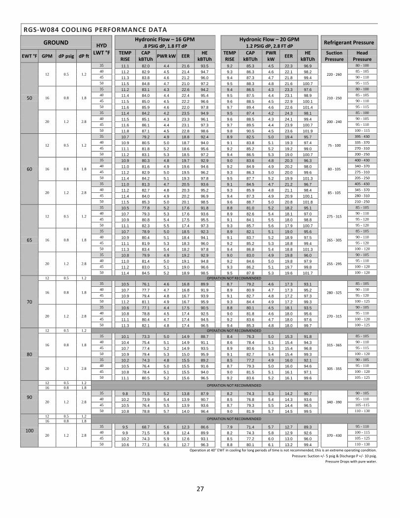
27
RGS-W084 COOLING PERFORMANCE DATA
GROUND HYD LWT °F
Hydronic Flow – 16 GPM .8 PSIG dP, 1.8 FT dP
Hydronic Flow – 20 GPM 1.2 PSIG dP, 2.8 FT dP
Refrigerant Pressure
EWT °F GPM dP psig dP ft TEMP RISE
CAP kBTUh
PWR kW EER HE
kBTUh
TEMP RISE
CAP kBTUh
PWR kW
EER HE
kBTUh
Suction Pressure
Head Pressure
50
12 0.5 1.2
35 11.1 82.0 4.4 21.6 93.5 9.2 85.3 4.5 22.3 96.9
220 - 260
80 - 100
40 11.2 82.9 4.5 21.4 94.7 9.3 86.3 4.6 22.1 98.2 85 - 105 45 11.3 83.8 4.6 21.2 96.0 9.4 87.3 4.7 21.8 99.4 90 - 110 50 11.5 84.8 4.7 21.0 97.2 9.5 88.3 4.8 21.6 100.7 95 - 115
16 0.8 1.8
35 11.2 83.1 4.3 22.6 94.2 9.4 86.5 4.3 23.3 97.6
210 - 250
80 - 100
40 11.4 84.0 4.4 22.4 95.4 9.5 87.5 4.4 23.1 98.9 85 - 105 45 11.5 85.0 4.5 22.2 96.6 9.6 88.5 4.5 22.9 100.1 90 - 110 50 11.6 85.9 4.6 22.0 97.8 9.7 89.4 4.6 22.6 101.4 95 - 115
20 1.2 2.8
35 11.4 84.2 4.2 23.5 94.9 9.5 87.4 4.2 24.3 98.1
200 - 240
85 - 100
40 11.5 85.1 4.3 23.3 96.1 9.6 88.5 4.3 24.1 99.4 90 - 105 45 11.6 86.1 4.4 23.1 97.3 9.7 89.5 4.4 23.9 100.7 95 - 110 50 11.8 87.1 4.5 22.8 98.6 9.8 90.5 4.5 23.6 101.9 100 - 115
60
12 0.5 1.2
35 10.7 79.2 4.9 18.8 92.4 8.9 82.5 5.0 19.4 95.7
75 - 100
395 - 430
40 10.9 80.5 5.0 18.7 94.0 9.1 83.8 5.1 19.3 97.4 335 - 370
45 11.1 81.8 5.2 18.6 95.6 9.2 85.2 5.2 19.2 99.0 270 - 310
50 11.2 83.1 5.3 18.5 97.2 9.4 86.5 5.3 19.0 100.7 200 - 250
16 0.8 1.8
35 10.9 80.3 4.8 19.7 92.9 9.0 83.6 4.8 20.3 96.3
80 - 105
400 - 430
40 11.0 81.6 4.9 19.6 94.6 9.2 84.9 4.9 20.2 98.0 340 - 370
45 11.2 82.9 5.0 19.5 96.2 9.3 86.3 5.0 20.0 99.6 275 - 310
50 11.4 84.2 5.1 19.3 97.8 9.5 87.7 5.2 19.9 101.3 205 - 250
20 1.2 2.8
35 11.0 81.3 4.7 20.5 93.6 9.1 84.5 4.7 21.2 96.7
85 - 105
405 - 430
40 11.2 82.7 4.8 20.3 95.2 9.3 85.9 4.8 21.1 98.4 345 - 370
45 11.4 84.0 4.9 20.2 96.9 9.4 87.3 4.9 20.9 100.1 280 - 310
50 11.5 85.3 5.0 20.1 98.5 9.6 88.7 5.0 20.8 101.8 210 - 250
65
12 0.5 1.2
35 10.5 77.8 5.2 17.6 91.8 8.8 81.0 5.2 18.2 95.1
275 - 315
85 - 105
40 10.7 79.3 5.3 17.6 93.6 8.9 82.6 5.4 18.1 97.0 90 - 110 45 10.9 80.8 5.4 17.5 95.5 9.1 84.1 5.5 18.0 98.8 95 - 120 50 11.1 82.3 5.5 17.4 97.3 9.3 85.7 5.6 17.9 100.7 95 - 120
16 0.8 1.8
35 10.7 78.9 5.0 18.5 92.3 8.9 82.1 5.1 19.0 95.6
265 - 305
85 - 105
40 10.9 80.4 5.1 18.4 94.1 9.1 83.7 5.2 18.9 97.5 90 - 110 45 11.1 81.9 5.3 18.3 96.0 9.2 85.2 5.3 18.8 99.4 95 - 120 50 11.3 83.4 5.4 18.2 97.8 9.4 86.8 5.4 18.8 101.3 100 - 120
20 1.2 2.8
35 10.8 79.9 4.9 19.2 92.9 9.0 83.0 4.9 19.8 96.0
255 - 295
90 - 105
40 11.0 81.4 5.0 19.1 94.8 9.2 84.6 5.0 19.8 97.9 95 - 110
45 11.2 83.0 5.1 19.0 96.6 9.3 86.2 5.1 19.7 99.8 100 - 120
50 11.4 84.5 5.2 18.9 98.5 9.5 87.8 5.3 19.6 101.7 100 - 120
70
12 0.5 1.2 OPERATION NOT RECOMMENDED
16 0.8 1.8
35 10.5 76.1 4.6 16.8 89.9 8.7 79.2 4.6 17.3 93.1
280 - 325
85 - 105
40 10.7 77.7 4.7 16.8 91.9 8.9 80.9 4.7 17.3 95.2 90 - 110 45 10.9 79.4 4.8 16.7 93.9 9.1 82.7 4.8 17.2 97.3 95 - 120 50 11.2 81.1 4.9 16.7 95.9 9.3 84.4 4.9 17.2 99.3 100 - 125
20 1.2 2.8
35 10.6 77.1 4.4 17.5 90.5 8.8 80.1 4.5 18.1 93.5
270 - 315
90 - 105
40 10.8 78.8 4.5 17.4 92.5 9.0 81.8 4.6 18.0 95.6 95 - 110
45 11.1 80.4 4.7 17.4 94.5 9.2 83.6 4.7 18.0 97.6 100 - 120
50 11.3 82.1 4.8 17.4 96.5 9.4 85.3 4.8 18.0 99.7 100 - 125
80
12 0.5 1.2 OPERATION NOT RECOMMENDED
16 0.8 1.8
35 10.1 73.3 5.0 14.9 88.7 8.4 76.3 5.0 15.3 91.8
315 - 365
85 - 105
40 10.4 75.4 5.1 14.9 91.1 8.6 78.4 5.1 15.4 94.3 90 - 110 45 10.7 77.4 5.2 14.9 93.5 8.9 80.6 5.3 15.4 96.8 95 - 115 50 10.9 79.4 5.3 15.0 95.9 9.1 82.7 5.4 15.4 99.3 100 - 120
20 1.2 2.8
35 10.2 74.3 4.8 15.5 89.2 8.5 77.2 4.9 16.0 92.1
305 - 355
90 - 105
40 10.5 76.4 5.0 15.5 91.6 8.7 79.3 5.0 16.0 94.6 95 - 110
45 10.8 78.4 5.1 15.5 94.0 9.0 81.5 5.1 16.1 97.1 100 - 120
50 11.1 80.5 5.2 15.6 96.5 9.2 83.6 5.2 16.1 99.6 105 - 125
90
12 0.5 1.2 OPERATION NOT RECOMMENDED
16 0.8 1.8
20 1.2 2.8
35 9.8 71.5 5.2 13.8 87.9 8.2 74.3 5.3 14.2 90.7
340 - 390
90 - 105
40 10.2 73.9 5.4 13.9 90.7 8.5 76.8 5.4 14.3 93.6 95 - 110
45 10.5 76.4 5.5 13.9 93.6 8.7 79.3 5.5 14.4 96.5 105 -115
50 10.8 78.8 5.7 14.0 96.4 9.0 81.9 5.7 14.5 99.5 110 - 130
100
12 0.5 1.2 OPERATION NOT RECOMMENDED
16 0.8 1.8
20 1.2 2.8
35 9.5 68.7 5.6 12.3 86.6 7.9 71.4 5.7 12.7 89.3
370 - 430
95 - 110
40 9.9 71.5 5.8 12.4 89.9 8.2 74.3 5.8 12.9 92.6 100 - 115
45 10.2 74.3 5.9 12.6 93.1 8.5 77.2 6.0 13.0 96.0 105 - 125
50 10.6 77.1 6.1 12.7 96.3 8.8 80.1 6.1 13.2 99.4 110 - 130
Operation at 40° EWT in cooling for long periods of time is not recommended, this is an extreme operating condition.
Pressure: Suction +/- 5 psig & Discharge P +/- 10 psig.
Pressure Drops with pure water.
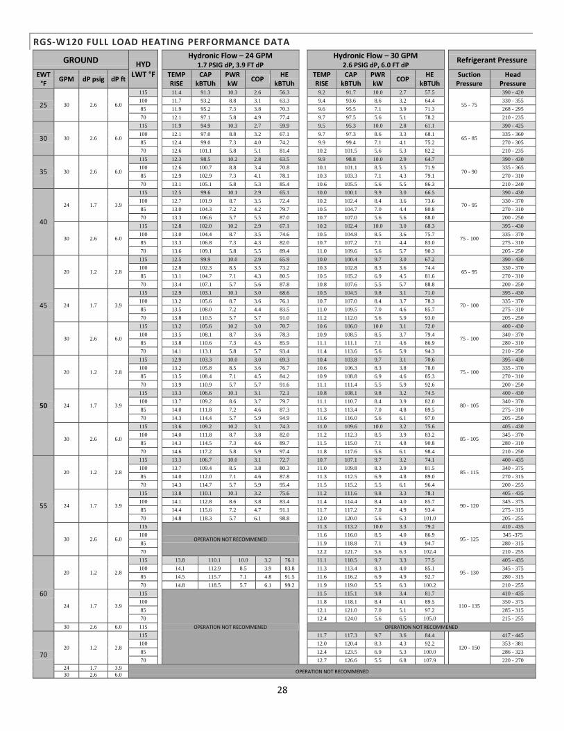
28
RGS-W120 FULL LOAD HEATING PERFORMANCE DATA
GROUND HYD LWT °F
Hydronic Flow – 24 GPM 1.7 PSIG dP, 3.9 FT dP
Hydronic Flow – 30 GPM 2.6 PSIG dP, 6.0 FT dP
Refrigerant Pressure
EWT °F
GPM dP psig dP ft TEMP RISE
CAP kBTUh
PWR kW
COP HE
kBTUh
TEMP RISE
CAP kBTUh
PWR kW
COP HE
kBTUh
Suction Pressure
Head Pressure
25 30 2.6 6.0
115 11.4 91.3 10.3 2.6 56.3 9.2 91.7 10.0 2.7 57.5
55 - 75
390 - 420
100 11.7 93.2 8.8 3.1 63.3 9.4 93.6 8.6 3.2 64.4 330 - 355
85 11.9 95.2 7.3 3.8 70.3 9.6 95.5 7.1 3.9 71.3 268 - 295
70 12.1 97.1 5.8 4.9 77.4 9.7 97.5 5.6 5.1 78.2 210 - 235
30 30 2.6 6.0
115 11.9 94.9 10.3 2.7 59.9 9.5 95.3 10.0 2.8 61.1
65 - 85
390 - 425
100 12.1 97.0 8.8 3.2 67.1 9.7 97.3 8.6 3.3 68.1 335 - 360
85 12.4 99.0 7.3 4.0 74.2 9.9 99.4 7.1 4.1 75.2 270 - 305
70 12.6 101.1 5.8 5.1 81.4 10.2 101.5 5.6 5.3 82.2 210 - 235
35 30 2.6 6.0
115 12.3 98.5 10.2 2.8 63.5 9.9 98.8 10.0 2.9 64.7
70 - 90
390 - 430
100 12.6 100.7 8.8 3.4 70.8 10.1 101.1 8.5 3.5 71.9 335 - 365
85 12.9 102.9 7.3 4.1 78.1 10.3 103.3 7.1 4.3 79.1 270 - 310
70 13.1 105.1 5.8 5.3 85.4 10.6 105.5 5.6 5.5 86.3 210 - 240
40
24 1.7 3.9
115 12.5 99.6 10.1 2.9 65.1 10.0 100.1 9.9 3.0 66.5
70 - 95
390 - 430
100 12.7 101.9 8.7 3.5 72.4 10.2 102.4 8.4 3.6 73.6 330 - 370
85 13.0 104.3 7.2 4.2 79.7 10.5 104.7 7.0 4.4 80.8 270 - 310
70 13.3 106.6 5.7 5.5 87.0 10.7 107.0 5.6 5.6 88.0 200 - 250
30 2.6 6.0
115 12.8 102.0 10.2 2.9 67.1 10.2 102.4 10.0 3.0 68.3
75 - 100
395 - 430
100 13.0 104.4 8.7 3.5 74.6 10.5 104.8 8.5 3.6 75.7 335 - 370
85 13.3 106.8 7.3 4.3 82.0 10.7 107.2 7.1 4.4 83.0 275 - 310
70 13.6 109.1 5.8 5.5 89.4 11.0 109.6 5.6 5.7 90.3 205 - 250
45
20 1.2 2.8
115 12.5 99.9 10.0 2.9 65.9 10.0 100.4 9.7 3.0 67.2
65 - 95
390 - 430
100 12.8 102.3 8.5 3.5 73.2 10.3 102.8 8.3 3.6 74.4 330 - 370
85 13.1 104.7 7.1 4.3 80.5 10.5 105.2 6.9 4.5 81.6 270 - 310
70 13.4 107.1 5.7 5.6 87.8 10.8 107.6 5.5 5.7 88.8 200 - 250
24 1.7 3.9
115 12.9 103.1 10.1 3.0 68.6 10.5 104.5 9.8 3.1 71.0
70 - 100
395 - 430
100 13.2 105.6 8.7 3.6 76.1 10.7 107.0 8.4 3.7 78.3 335 - 370
85 13.5 108.0 7.2 4.4 83.5 11.0 109.5 7.0 4.6 85.7 275 - 310
70 13.8 110.5 5.7 5.7 91.0 11.2 112.0 5.6 5.9 93.0 205 - 250
30 2.6 6.0
115 13.2 105.6 10.2 3.0 70.7 10.6 106.0 10.0 3.1 72.0
75 - 100
400 - 430
100 13.5 108.1 8.7 3.6 78.3 10.9 108.5 8.5 3.7 79.4 340 - 370
85 13.8 110.6 7.3 4.5 85.9 11.1 111.1 7.1 4.6 86.9 280 - 310
70 14.1 113.1 5.8 5.7 93.4 11.4 113.6 5.6 5.9 94.3 210 - 250
50
20 1.2 2.8
115 12.9 103.3 10.0 3.0 69.3 10.4 103.8 9.7 3.1 70.6
75 - 100
395 - 430
100 13.2 105.8 8.5 3.6 76.7 10.6 106.3 8.3 3.8 78.0 335 - 370
85 13.5 108.4 7.1 4.5 84.2 10.9 108.8 6.9 4.6 85.3 270 - 310
70 13.9 110.9 5.7 5.7 91.6 11.1 111.4 5.5 5.9 92.6 200 - 250
24 1.7 3.9
115 13.3 106.6 10.1 3.1 72.1 10.8 108.1 9.8 3.2 74.5
80 - 105
400 - 430
100 13.7 109.2 8.6 3.7 79.7 11.1 110.7 8.4 3.9 82.0 340 - 370
85 14.0 111.8 7.2 4.6 87.3 11.3 113.4 7.0 4.8 89.5 275 - 310
70 14.3 114.4 5.7 5.9 94.9 11.6 116.0 5.6 6.1 97.0 205 - 250
30 2.6 6.0
115 13.6 109.2 10.2 3.1 74.3 11.0 109.6 10.0 3.2 75.6
85 - 105
405 - 430
100 14.0 111.8 8.7 3.8 82.0 11.2 112.3 8.5 3.9 83.2 345 - 370
85 14.3 114.5 7.3 4.6 89.7 11.5 115.0 7.1 4.8 90.8 280 - 310
70 14.6 117.2 5.8 5.9 97.4 11.8 117.6 5.6 6.1 98.4 210 - 250
55
20 1.2 2.8
115 13.3 106.7 10.0 3.1 72.7 10.7 107.1 9.7 3.2 74.1
85 - 115
400 - 435
100 13.7 109.4 8.5 3.8 80.3 11.0 109.8 8.3 3.9 81.5 340 - 375
85 14.0 112.0 7.1 4.6 87.8 11.3 112.5 6.9 4.8 89.0 270 - 315
70 14.3 114.7 5.7 5.9 95.4 11.5 115.2 5.5 6.1 96.4 200 - 255
24 1.7 3.9
115 13.8 110.1 10.1 3.2 75.6 11.2 111.6 9.8 3.3 78.1
90 - 120
405 - 435
100 14.1 112.8 8.6 3.8 83.4 11.4 114.4 8.4 4.0 85.7 345 - 375
85 14.4 115.6 7.2 4.7 91.1 11.7 117.2 7.0 4.9 93.4 275 - 315
70 14.8 118.3 5.7 6.1 98.8 12.0 120.0 5.6 6.3 101.0 205 - 255
30 2.6 6.0
115
OPERATION NOT RECOMMENED
11.3 113.2 10.0 3.3 79.2
95 - 125
410 - 435
100 11.6 116.0 8.5 4.0 86.9 345 -375
85 11.9 118.8 7.1 4.9 94.7 280 - 315
70 12.2 121.7 5.6 6.3 102.4 210 - 255
60
20 1.2 2.8
115 13.8 110.1 10.0 3.2 76.1 11.1 110.5 9.7 3.3 77.5
95 - 130
405 - 435
100 14.1 112.9 8.5 3.9 83.8 11.3 113.4 8.3 4.0 85.1 345 - 375
85 14.5 115.7 7.1 4.8 91.5 11.6 116.2 6.9 4.9 92.7 280 - 315
70 14.8 118.5 5.7 6.1 99.2 11.9 119.0 5.5 6.3 100.2 210 - 255
24 1.7 3.9
115
OPERATION NOT RECOMMENED
11.5 115.1 9.8 3.4 81.7
110 - 135
410 - 435
100 11.8 118.1 8.4 4.1 89.5 350 - 375
85 12.1 121.0 7.0 5.1 97.2 285 - 315
70 12.4 124.0 5.6 6.5 105.0 215 - 255
30 2.6 6.0 115 OPERATION NOT RECOMMENED
70 20 1.2 2.8
115 11.7 117.3 9.7 3.6 84.4
120 - 150
417 - 445
100 12.0 120.4 8.3 4.3 92.2 353 - 381
85 12.4 123.5 6.9 5.3 100.0 286 - 323
70 12.7 126.6 5.5 6.8 107.9 220 - 270
24 1.7 3.9 OPERATION NOT RECOMMENED
30 2.6 6.0
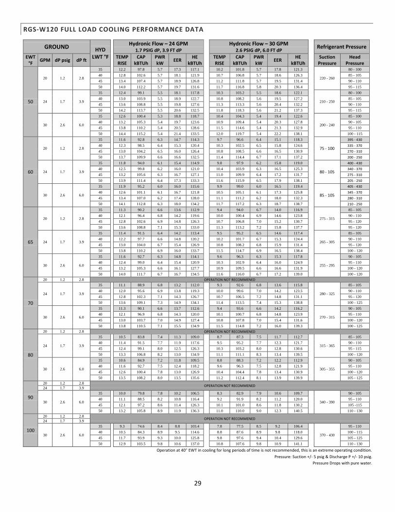
29
RGS-W120 FULL LOAD COOLING PERFORMANCE DATA
GROUND HYD LWT °F
Hydronic Flow – 24 GPM 1.7 PSIG dP, 3.9 FT dP
Hydronic Flow – 30 GPM 2.6 PSIG dP, 6.0 FT dP
Refrigerant Pressure
EWT °F
GPM dP psig dP ft TEMP RISE
CAP kBTUh
PWR kW
EER HE
kBTUh
TEMP RISE
CAP kBTUh
PWR kW
EER HE
kBTUh
Suction Pressure
Head Pressure
50
20 1.2 2.8
35 12.2 97.8 5.7 17.3 117.1 10.2 101.8 5.7 17.8 121.3
220 - 260
80 - 100
40 12.8 102.6 5.7 18.1 121.9 10.7 106.8 5.7 18.6 126.3 85 - 105 45 13.4 107.4 5.7 18.9 126.8 11.2 111.8 5.7 19.5 131.4 90 - 110 50 14.0 112.2 5.7 19.7 131.6 11.7 116.8 5.8 20.3 136.4 95 - 115
24 1.7 3.9
35 12.4 99.1 5.5 18.1 117.8 10.3 103.2 5.5 18.6 122.1
210 - 250
80 - 100
40 13.0 103.9 5.5 18.9 122.7 10.8 108.2 5.6 19.5 127.2 85 - 105 45 13.6 108.8 5.5 19.8 127.6 11.3 113.3 5.6 20.4 132.2 90 - 110 50 14.2 113.7 5.5 20.6 132.5 11.8 118.3 5.6 21.2 137.3 95 - 115
30 2.6 6.0
35 12.6 100.4 5.3 18.8 118.7 10.4 104.3 5.4 19.4 122.6
200 - 240
85 - 100
40 13.2 105.3 5.4 19.7 123.6 10.9 109.4 5.4 20.3 127.8 90 - 105 45 13.8 110.2 5.4 20.5 128.6 11.5 114.6 5.4 21.3 132.9 95 - 110 50 14.4 115.2 5.4 21.4 133.5 12.0 119.7 5.4 22.2 138.1 100 - 115
60
20 1.2 2.8
35 11.6 92.8 6.3 14.7 114.3 9.7 96.6 6.4 15.1 118.3
75 - 100
395 - 430
40 12.3 98.5 6.4 15.3 120.4 10.3 102.5 6.5 15.8 124.6 335 - 370
45 13.0 104.2 6.5 16.0 126.4 10.8 108.5 6.6 16.5 130.9 270 - 310
50 13.7 109.9 6.6 16.6 132.5 11.4 114.4 6.7 17.1 137.2 200 - 250
24 1.7 3.9
35 11.8 94.0 6.1 15.4 114.9 9.8 97.9 6.2 15.8 119.0
80 - 105
400 - 430
40 12.5 99.8 6.2 16.0 121.0 10.4 103.9 6.3 16.5 125.3 340 - 370
45 13.2 105.6 6.3 16.7 127.1 11.0 109.9 6.4 17.2 131.7 275 - 310
50 13.9 111.4 6.4 17.3 133.3 11.6 115.9 6.5 17.9 138.1 205 - 250
30 2.6 6.0
35 11.9 95.2 6.0 16.0 115.6 9.9 99.0 6.0 16.5 119.4
85 - 105
405 - 430
40 12.6 101.1 6.1 16.7 121.8 10.5 105.1 6.1 17.3 125.8 345 - 370
45 13.4 107.0 6.2 17.4 128.0 11.1 111.2 6.2 18.0 132.3 280 - 310
50 14.1 112.8 6.3 18.0 134.2 11.7 117.2 6.3 18.7 138.7 210 - 250
65
20 1.2 2.8
35 11.3 90.2 6.6 13.6 112.9 9.4 94.0 6.7 14.0 116.9
275 - 315
85 - 105
40 12.1 96.4 6.8 14.2 119.6 10.0 100.4 6.9 14.6 123.8 90 - 110 45 12.8 102.6 6.9 14.8 126.3 10.7 106.8 7.0 15.2 130.7 95 - 120 50 13.6 108.8 7.1 15.3 133.0 11.3 113.2 7.2 15.8 137.7 95 - 120
24 1.7 3.9
35 11.4 91.5 6.4 14.2 113.4 9.5 95.2 6.5 14.6 117.4
265 - 305
85 - 105
40 12.2 97.7 6.6 14.8 120.2 10.2 101.7 6.7 15.3 124.4 90 - 110 45 13.0 104.0 6.7 15.4 126.9 10.8 108.2 6.8 15.9 131.4 95 - 120 50 13.8 110.2 6.9 16.0 133.7 11.5 114.7 6.9 16.5 138.4 100 - 120
30 2.6 6.0
35 11.6 92.7 6.3 14.8 114.1 9.6 96.3 6.3 15.3 117.8
255 - 295
90 - 105
40 12.4 99.0 6.4 15.4 120.9 10.3 102.9 6.4 16.0 124.9 95 - 110
45 13.2 105.3 6.6 16.1 127.7 10.9 109.5 6.6 16.6 131.9 100 - 120
50 14.0 111.7 6.7 16.7 134.5 11.6 116.0 6.7 17.2 139.0 100 - 120
70
20 1.2 2.8 OPERATION NOT RECOMMENED
24 1.7 3.9
35 11.1 88.9 6.8 13.2 112.0 9.3 92.6 6.8 13.6 115.8
280 - 325
85 - 105
40 12.0 95.6 6.9 13.8 119.3 10.0 99.6 7.0 14.2 123.5 90 - 110 45 12.8 102.3 7.1 14.3 126.7 10.7 106.5 7.2 14.8 131.1 95 - 120 50 13.6 109.1 7.3 14.9 134.1 11.4 113.5 7.4 15.3 138.8 100 - 125
30 2.6 6.0
35 11.3 90.1 6.6 13.7 112.6 9.4 93.6 6.6 14.2 116.2
270 - 315
90 - 105
40 12.1 96.9 6.8 14.3 120.0 10.1 100.7 6.8 14.8 123.9 95 - 110
45 13.0 103.7 7.0 14.9 127.4 10.8 107.8 7.0 15.4 131.6 100 - 120
50 13.8 110.5 7.1 15.5 134.9 11.5 114.8 7.2 16.0 139.3 100 - 125
80
20 1.2 2.8 OPERATION NOT RECOMMENED
24 1.7 3.9
35 10.5 83.8 7.4 11.3 109.0 8.7 87.3 7.5 11.7 112.7
315 - 365
85 - 105
40 11.4 91.5 7.7 11.9 117.6 9.5 95.2 7.7 12.3 121.7 90 - 110 45 12.4 99.1 8.0 12.5 126.3 10.3 103.2 8.0 12.8 130.6 95 - 115 50 13.3 106.8 8.2 13.0 134.9 11.1 111.1 8.3 13.4 139.5 100 - 120
30 2.6 6.0
35 10.6 84.9 7.2 11.8 109.5 8.8 88.3 7.2 12.2 112.9
305 - 355
90 - 105
40 11.6 92.7 7.5 12.4 118.2 9.6 96.3 7.5 12.8 121.9 95 - 110
45 12.6 100.4 7.8 13.0 126.9 10.4 104.4 7.8 13.4 130.9 100 - 120
50 13.5 108.2 8.0 13.5 135.6 11.2 112.4 8.1 13.9 139.9 105 - 125
90
20 1.2 2.8 OPERATION NOT RECOMMENED
24 1.7 3.9
30 2.6 6.0
35 10.0 79.8 7.8 10.2 106.5 8.3 82.9 7.9 10.6 109.7
340 - 390
90 - 105
40 11.1 88.5 8.2 10.8 116.4 9.2 91.9 8.2 11.2 120.0 95 - 110
45 12.1 97.2 8.6 11.4 126.3 10.1 101.0 8.6 11.8 130.2 105 -115
50 13.2 105.8 8.9 11.9 136.3 11.0 110.0 9.0 12.3 140.5 110 - 130
100
20 1.2 2.8 OPERATION NOT RECOMMENED
24 1.7 3.9
30 2.6 6.0
35 9.3 74.6 8.4 8.8 103.4 7.8 77.5 8.5 9.2 106.4
370 - 430
95 - 110
40 10.5 84.3 8.9 9.5 114.6 8.8 87.6 8.9 9.8 118.0 100 - 115
45 11.7 93.9 9.3 10.0 125.8 9.8 97.6 9.4 10.4 129.6 105 - 125
50 12.9 103.5 9.8 10.6 137.0 10.8 107.6 9.8 10.9 141.1 110 - 130
Operation at 40° EWT in cooling for long periods of time is not recommended, this is an extreme operating condition.
Pressure: Suction +/- 5 psig & Discharge P +/- 10 psig.
Pressure Drops with pure water.

30
RG-W120 PART LOAD HEATING PERFORMANCE DATA
GROUND HYD LWT °F
Hydronic Flow – 24 GPM 1.7 PSIG dP, 3.9 FT dP
Hydronic Flow – 30 GPM 2.6 PSIG dP, 6.0 FT dP
Refrigerant Pressure
EWT °F GPM dP psig dP ft TEMP RISE
CAP kBTUh
PWR kW
COP HE
kBTUh
TEMP RISE
CAP kBTUh
PWR kW
COP HE
kBTUh
Suction Pressure
Head Pressure
25 30 2.6 6.0
115 5.7 45.5 4.6 2.9 29.8 4.6 45.7 4.5 3.0 30.3
65 - 85
375 - 400
100 5.7 46.0 4.0 3.4 32.4 4.6 46.1 3.9 3.5 32.9 310 - 335
85 5.8 46.4 3.3 4.1 35.0 4.7 46.6 3.3 4.2 35.4 240 - 265
70 5.9 46.9 2.7 5.1 37.6 4.7 47.1 2.7 5.2 38.0 180 - 210
30 30 2.6 6.0
115 5.9 47.1 4.6 3.0 31.3 4.7 47.3 4.5 3.1 31.9
73 - 92
380 - 405
100 6.0 48.2 4.0 3.5 34.6 4.8 48.4 3.9 3.6 35.1 315 - 340
85 6.2 49.3 3.4 4.3 37.8 4.9 49.5 3.3 4.4 38.3 250 - 275
70 6.3 50.4 2.7 5.4 41.0 5.1 50.6 2.7 5.5 41.5 190 - 215
35 30 2.6 6.0
115 6.1 48.7 4.6 3.1 32.9 4.9 48.9 4.5 3.2 33.4
80 - 100
380 - 405
100 6.3 50.4 4.0 3.7 36.7 5.1 50.6 3.9 3.8 37.3 320 - 345
85 6.5 52.2 3.4 4.5 40.6 5.2 52.4 3.3 4.6 41.1 250 - 275
70 6.7 53.9 2.8 5.7 44.5 5.4 54.1 2.7 5.9 44.9 190 - 215
40
24 1.7 3.9
115 6.1 49.1 4.6 3.1 33.4 4.9 49.3 4.5 3.2 34.0
80 - 105
380 - 405
100 6.4 51.4 4.0 3.8 37.8 5.2 51.7 3.9 3.9 38.4 320 - 345
85 6.7 53.8 3.4 4.7 42.2 5.4 54.0 3.3 4.8 42.8 255 - 280
70 7.0 56.1 2.8 5.9 46.7 5.6 56.4 2.7 6.1 47.2 190 - 215
30 2.6 6.0
115 6.3 50.3 4.7 3.2 34.4 5.0 50.5 4.5 3.3 35.0
85 - 105
380 - 405
100 6.6 52.7 4.0 3.8 38.9 5.3 52.9 3.9 3.9 39.4 320 - 345
85 6.9 55.1 3.4 4.7 43.4 5.5 55.3 3.3 4.9 43.9 255 - 280
70 7.2 57.5 2.8 6.0 47.9 5.8 57.7 2.7 6.2 48.4 190 - 215
45
20 1.2 2.8
115 6.1 49.1 4.6 3.2 33.5 4.9 49.3 4.4 3.3 34.1
80 - 107
380 - 410
100 6.5 52.0 4.0 3.8 38.4 5.2 52.2 3.9 4.0 39.0 315 - 345
85 6.9 54.8 3.4 4.8 43.4 5.5 55.1 3.3 4.9 43.9 255 - 285
70 7.2 57.7 2.8 6.1 48.3 5.8 58.0 2.7 6.3 48.8 190 - 210
24 1.7 3.9
115 6.3 50.6 4.6 3.2 34.9 5.1 51.3 4.5 3.3 36.0
85 - 112
380 - 410
100 6.7 53.6 4.0 3.9 39.9 5.4 54.4 3.9 4.1 41.0 315 - 345
85 7.1 56.6 3.4 4.9 45.0 5.7 57.4 3.3 5.1 46.1 255 - 285
70 7.4 59.6 2.8 6.2 50.0 6.0 60.4 2.7 6.5 51.1 190 - 210
30 2.6 6.0
115 6.5 51.9 4.7 3.3 35.9 5.2 52.1 4.6 3.3 36.5
90 - 112
385 - 410
100 6.9 54.9 4.1 4.0 41.1 5.5 55.1 4.0 4.1 41.6 320 - 345
85 7.2 57.9 3.4 4.9 46.2 5.8 58.2 3.4 5.1 46.7 260 - 285
70 7.6 61.0 2.8 6.3 51.4 6.1 61.2 2.8 6.5 51.8 195 - 210
50
20 1.2 2.8
115 6.3 50.6 4.6 3.2 35.0 5.1 50.8 4.5 3.3 35.6
88 - 115
380 - 415
100 6.8 54.1 4.0 4.0 40.5 5.4 54.3 3.9 4.1 41.1 320 - 350
85 7.2 57.6 3.4 5.0 46.0 5.8 57.8 3.3 5.2 46.6 255 - 285
70 7.6 61.1 2.8 6.4 51.6 6.1 61.3 2.7 6.6 52.1 195 - 225
24 1.7 3.9
115 6.5 52.2 4.6 3.3 36.4 5.3 52.9 4.5 3.4 37.5
93 - 120
385 - 415
100 7.0 55.8 4.0 4.1 42.0 5.7 56.6 3.9 4.2 43.2 320 - 350
85 7.4 59.4 3.4 5.1 47.7 6.0 60.2 3.3 5.3 48.9 255 - 285
70 7.9 63.0 2.8 6.6 53.4 6.4 63.9 2.7 6.8 54.5 195 - 225
30 2.6 6.0
115 6.7 53.4 4.7 3.3 37.5 5.4 53.7 4.6 3.4 38.1
98 - 120
390 - 415
100 7.1 57.1 4.1 4.1 43.2 5.7 57.4 4.0 4.2 43.8 325 - 350
85 7.6 60.8 3.5 5.2 49.0 6.1 61.1 3.4 5.3 49.5 260 - 285
70 8.1 64.5 2.8 6.6 54.8 6.5 64.8 2.8 6.8 55.3 200 - 225
55
20 1.2 2.8
115 6.5 52.1 4.6 3.3 36.4 5.2 52.3 4.5 3.4 37.1
94 - 121
385 - 415
100 7.0 56.2 4.0 4.1 42.5 5.6 56.4 3.9 4.3 43.2 320 - 350
85 7.5 60.3 3.4 5.2 48.7 6.1 60.5 3.3 5.4 49.3 255 - 285
70 8.0 64.4 2.8 6.7 54.8 6.5 64.7 2.7 6.9 55.4 195 - 225
24 1.7 3.9
115 6.7 53.7 4.7 3.4 37.9 5.4 54.5 4.5 3.5 39.0
99 - 126
385 - 415
100 7.2 58.0 4.0 4.2 44.2 5.9 58.8 3.9 4.4 45.3 320 - 350
85 7.8 62.2 3.4 5.3 50.4 6.3 63.1 3.4 5.5 51.6 255 - 285
70 8.3 66.4 2.8 6.8 56.7 6.7 67.4 2.8 7.1 57.9 195 - 225
30 2.6 6.0
115
OPERATION NOT RECOMMENED
5.5 55.2 4.6 3.5 39.6
95 - 125
410 - 435 95 - 125 410 - 435
100 6.0 59.6 4.0 4.4 46.0 345 -375 345 -375
85 6.4 64.0 3.4 5.5 52.4 280 - 315 280 - 315
70 6.8 68.3 2.8 7.1 58.7 210 - 255 210 - 255
60
20 1.2 2.8
115 6.7 53.6 4.6 3.4 37.9 5.4 53.8 4.5 3.5 38.5
105 - 132
385 - 415
100 7.3 58.3 4.0 4.3 44.6 5.9 58.6 3.9 4.4 45.2 325 - 350
85 7.9 63.0 3.4 5.4 51.3 6.3 63.3 3.3 5.6 51.9 260 - 285
70 8.5 67.7 2.8 7.0 58.1 6.8 68.0 2.8 7.2 58.6 195 - 225
24 1.7 3.9
115
OPERATION NOT RECOMMENED
5.6 56.1 4.5 3.6 40.6
110 - 135
410 - 435
100 6.1 61.0 4.0 4.5 47.5 350 - 375
85 6.6 65.9 3.4 5.7 54.4 285 - 315
70 7.1 70.9 2.8 7.4 61.3 215 - 255
30 2.6 6.0 115 OPERATION NOT RECOMMENED
70 20 1.2 2.8
115 5.7 56.8 4.5 3.7 41.4
123 - 146
395 - 415
100 6.3 62.8 3.9 4.7 49.4 330 - 350
85 6.9 68.8 3.4 6.0 57.3 270 - 290
70 7.5 74.7 2.8 7.8 65.2 205 - 225
24 1.7 3.9 OPERATION NOT RECOMMENED
30 2.6 6.0
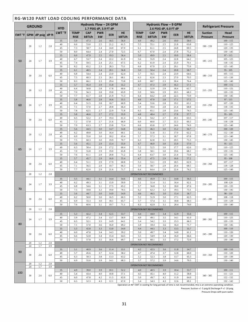
31
RG-W120 PART LOAD COOLING PERFORMANCE DATA
GROUND HYD LWT °F
Hydronic Flow – 24 GPM 1.7 PSIG dP, 3.9 FT dP
Hydronic Flow – 9 GPM 2.6 PSIG dP, 6.0 FT dP
Refrigerant Pressure
EWT °F GPM dP psig dP ft TEMP RISE
CAP kBTUh
PWR kW
EER HE
kBTUh
TEMP RISE
CAP kBTUh
PWR kW
EER HE
kBTUh
Suction Pressure
Head Pressure
50
20 1.2 2.8
35 5.9 47.3 2.6 18.5 56.0 4.9 49.2 2.6 19.0 58.0
190 - 220
100 - 115
40 6.6 53.0 2.5 21.2 61.5 5.5 55.1 2.5 21.8 63.8 110 - 125 45 7.3 58.7 2.4 24.0 67.0 6.1 61.1 2.5 24.8 69.5 120 - 135 50 8.0 64.4 2.4 27.0 72.5 6.7 67.0 2.4 27.8 75.2 130 - 145
24 1.7 3.9
35 6.0 47.9 2.5 19.3 56.4 5.0 49.9 2.5 19.9 58.4
185 - 215
97 - 115
40 6.7 53.7 2.4 22.2 61.9 5.6 55.9 2.4 22.8 64.2 105 - 125 45 7.4 59.5 2.4 25.1 67.5 6.2 61.9 2.4 25.9 70.1 118 - 135 50 8.2 65.2 2.3 28.3 73.1 6.8 67.9 2.3 29.1 75.9 125 - 145
30 2.6 6.0
35 6.1 48.5 2.4 20.1 56.8 5.0 50.4 2.4 20.8 58.7
180 - 210
95 - 105
40 6.8 54.4 2.4 23.0 62.4 5.7 56.5 2.4 23.9 64.6 105 - 115 45 7.5 60.3 2.3 26.1 68.1 6.3 62.6 2.3 27.0 70.5 115 - 130 50 8.3 66.1 2.3 29.4 73.8 6.9 68.7 2.3 30.4 76.4 125 - 140
60
20 1.2 2.8
35 5.7 45.4 2.9 15.8 55.2 4.7 47.3 2.9 16.3 57.1
215 - 255
100 - 115
40 6.4 50.8 2.8 17.8 60.6 5.3 52.9 2.9 18.4 62.7 110 - 125 45 7.0 56.3 2.8 19.8 65.9 5.9 58.6 2.9 20.5 68.3 120 - 135 50 7.7 61.7 2.8 21.9 71.3 6.4 64.2 2.8 22.5 73.9 130 - 145
24 1.7 3.9
35 5.8 46.0 2.8 16.6 55.5 4.8 47.9 2.8 17.1 57.5
210 - 250
97 - 115
40 6.4 51.5 2.8 18.7 60.9 5.4 53.6 2.8 19.2 63.1 107 - 120 45 7.1 57.0 2.7 20.8 66.4 5.9 59.4 2.8 21.4 68.8 118 - 135 50 7.8 62.5 2.7 22.9 71.8 6.5 65.1 2.8 23.6 74.5 125 - 145
30 2.6 6.0
35 5.8 46.6 2.7 17.2 55.9 4.8 48.4 2.7 17.8 57.7
205 - 245
95 - 105
40 6.5 52.2 2.7 19.4 61.4 5.4 54.2 2.7 20.1 63.5 107 - 117 45 7.2 57.8 2.7 21.6 66.9 6.0 60.0 2.7 22.3 69.2 118 - 128 50 7.9 63.3 2.7 23.8 72.4 6.6 65.8 2.7 24.6 74.9 125 - 140
65
20 1.2 2.8
35 5.6 44.5 3.0 14.7 54.8 4.6 46.3 3.0 15.2 56.7
240 - 270
100 - 120
40 6.2 49.8 3.0 16.4 60.1 5.2 51.8 3.1 17.0 62.2 112 - 130 45 6.9 55.0 3.0 18.2 65.4 5.7 57.3 3.1 18.7 67.8 123 - 140 50 7.5 60.3 3.0 19.9 70.7 6.3 62.8 3.1 20.5 73.3 130 - 145
24 1.7 3.9
35 5.6 45.1 2.9 15.4 55.0 4.7 46.9 3.0 15.9 57.0
235 - 265
95 - 115
40 6.3 50.4 2.9 17.2 60.4 5.2 52.5 3.0 17.7 62.6 110 - 125 45 7.0 55.8 2.9 19.0 65.8 5.8 58.1 3.0 19.6 68.2 120 - 135 50 7.6 61.1 2.9 20.8 71.2 6.4 63.7 3.0 21.4 73.8 125 - 145
30 2.6 6.0
35 5.7 45.7 2.9 16.0 55.4 4.7 47.5 2.9 16.6 57.2
230 - 260
95 - 108
40 6.4 51.1 2.9 17.9 60.8 5.3 53.1 2.9 18.5 62.9 107 - 117
45 7.1 56.5 2.9 19.7 66.3 5.9 58.7 2.9 20.4 68.5 118 - 128
50 7.7 62.0 2.9 21.6 71.7 6.4 64.4 2.9 22.4 74.2 125 - 140
70
20 1.2 2.8 OPERATION NOT RECOMMENED 6.5 52.2 4.6 3.3 36.4 5.3 52.9 4.5 3.4 37.5
24 1.7 3.9
35 5.5 44.1 3.1 14.4 54.6 4.6 45.9 3.1 14.8 56.5
250 - 285
100 - 115
40 6.2 49.3 3.1 15.9 59.9 5.1 51.4 3.1 16.4 62.1 108 -120 45 6.8 54.6 3.1 17.5 65.2 5.7 56.8 3.2 18.0 67.6 120 - 135 50 7.5 59.8 3.2 19.0 70.5 6.2 62.2 3.2 19.5 73.1 130 - 145
30 2.6 6.0
35 5.6 44.7 3.0 14.9 54.9 4.6 46.5 3.0 15.4 56.7
245 - 280
98 - 110
40 6.2 50.0 3.0 16.5 60.3 5.2 51.9 3.0 17.1 62.5 108 - 118
45 6.9 55.3 3.0 18.1 65.7 5.7 57.4 3.1 18.8 68.3 119 - 129
50 7.6 60.6 3.1 19.7 71.1 6.3 62.9 3.1 20.4 74.0 130 - 140
80
20 1.2 2.8 OPERATION NOT RECOMMENED 7.0 56.2 4.0 4.1 42.5 5.6 56.4 3.9 4.3 43.2
24 1.7 3.9
35 5.3 42.2 3.4 12.5 53.7 4.4 44.0 3.4 12.9 55.6
280 - 282
100 - 115
40 5.9 47.2 3.4 13.7 58.9 4.9 49.1 3.5 14.1 61.0 110 - 125 45 6.5 52.1 3.5 14.9 64.1 5.4 54.2 3.5 15.3 66.3 120 - 135 50 7.1 57.0 3.6 16.0 69.2 5.9 59.4 3.6 16.4 71.7 130 - 145
30 2.6 6.0
35 5.3 42.8 3.3 13.0 54.0 4.4 44.5 3.3 13.5 55.7
245 - 280
100 - 110
40 6.0 47.8 3.4 14.3 59.2 5.0 49.7 3.4 14.8 61.1 110 - 120
45 6.6 52.8 3.4 15.4 64.5 5.5 54.9 3.4 16.0 66.6 120 - 130
50 7.2 57.8 3.5 16.6 69.7 6.0 60.1 3.5 17.2 72.0 130 - 140
90
20 1.2 2.8 OPERATION NOT RECOMMENED
24 1.7 3.9
30 2.6 6.0
35 5.1 40.9 3.6 11.4 53.1 4.2 42.5 3.6 11.8 54.7
310 - 350
100 - 110
40 5.7 45.6 3.7 12.4 58.2 4.7 47.4 3.7 12.8 60.0 110 - 120
45 6.3 50.3 3.8 13.3 63.2 5.2 52.3 3.8 13.7 65.3 120 - 130
50 6.9 55.0 3.9 14.1 68.3 5.7 57.2 3.9 14.6 70.5 130 - 140
100
20 1.2 2.8 OPERATION NOT RECOMMENED
24 1.7 3.9
30 2.6 6.0
35 4.9 39.0 3.9 10.1 52.2 4.0 40.5 3.9 10.4 53.7
340 - 385
100 - 111
40 5.4 43.4 4.0 10.8 57.1 4.5 45.1 4.0 11.2 58.8 111 - 121
45 6.0 47.8 4.2 11.5 62.0 5.0 49.7 4.2 11.9 64.0 122 - 132
50 6.5 52.3 4.3 12.1 67.0 5.4 54.3 4.3 12.6 69.1 132 - 142
Operation at 40° EWT in cooling for long periods of time is not recommended, this is an extreme operating condition.
Pressure: Suction +/- 5 psig & Discharge P +/- 10 psig.
Pressure Drops with pure water.

32
PHYSICAL DIMENSIONS
Dimension RGS-
W036 RGS-W048 RGS-W060
RGS-W072
RGS-W084
RGS-W120
A 23.4 23.4 23.4 27.0 27.0
B 29.2 29.2 29.2 27.5 27.5
C 25.8 25.8 25.8 26.1 26.1
D 6.1 6.1 6.1 - -
E 3.2 3.2 3.2 - -
F 18.1 18.1 18.1 - -
G 2.8 2.8 2.8 - -
H 18.3 18.3 18.3 - -
J 6.5 6.5 6.5 - -
K 4.4 4.4 4.4 - -
L 2.0 2.0 2.0 - -
M 26.5 26.5 26.5 - -
N 20.8 20.8 20.8 - -
P 25.1 25.1 25.1 - -
All measurements in inches
RGS-W084-RGS-W120

33
ELECTRICAL DATA
Model Voltage Phase
Frequency (Hz)
Compressor Hydronic Pump Without FlowCenter
Total FLA
Min. Amp.
Max Fuse RLA LRA HP FLA LRA
RGS-W036
208/230-1, 60 17.9 112 1/3 3.6 -- 21.5 26.0 40
208/230-3, 60 13.2 88 1/3 3.6 -- 16.8 20.1 30
460-3, 60 6.0 440 1/3 1.1 -- 7.1 8.6 10
200/220-3, 50 13.2 95 1/3 3.6 -- 16.8 20.1 30
RGS-W048
208/230-1, 60 25.0 134 1/3 3.6 -- 28.6 34.9 55
208/230-3, 60 15.9 110 1/3 3.6 -- 19.5 23.5 35
460-3, 60 7.1 52 1/3 1.1 -- 8.2 10.0 15
380-3, 60 7.9 66 1/3 1.1 -- 9.0 11.0 15
200/220-3, 50 15.0 110 1/3 3.6 -- 18.6 22.4 35
RGS-W060
208/230-1, 60 28.3 178 1/3 3.6 -- 31.9 39.0 65
208/230-3, 60 19.2 136 1/3 3.6 -- 22.8 27.6 45
460-3, 60 8.7 66 1/3 1.1 -- 9.8 12.0 20
380-3, 60 10.7 83 1/3 1.1 -- 11.8 14.5 25
200/220-3, 50 18.8 146 1/3 3.6 -- 22.4 27.1 45
RGS-W072
208/230-1, 60 32.1 148 1/3 3.6 -- 35.7 43.7 75
208/230-3, 60 23.2 164 1/3 3.6 -- 26.8 32.6 55
460-3, 60 11.2 75 1/3 1.1 -- 12.3 15.1 25
380-3, 60 12.2 73 1/3 1.1 -- 13.3 16.4 25
200/220-3, 50 21.7 179 1/3 3.6 -- 25.3 30.7 50
RGS-W084
208/230-1, 60 32.1 185 1/3 3.6 -- 35.7 43.7 75
208/230-3, 60 25.0 164 1/3 3.6 -- 28.6 34.9 55
460-3, 60 12.2 100 1/3 1.1 -- 13.3 16.4 25
380-3, 60 13.9 94 1/3 1.1 -- 15.0 18.5 30
200/220-3, 50 25.0 179 1/3 3.6 -- 28.6 34.9 55
RGS-W120
208/230-1, 60 30.1x2 158x2 1/3 3.6 -- 63.8 78.9 105
208/230-3, 60 20.5x2 155x2 1/3 3.6 -- 44.6 54.9 70
460-3, 60 9.6x2 75x2 1/3 1.1 -- 20.3 25.1 30
380-3, 60 9.6x2 67x2 1/3 1.1 -- 20.3 25.1 30
200/220-3, 50 20.5x2 170x2 1/3 3.6 -- 44.6 54.9 70

34
WATER COIL PRESSURE DROP RATINGS
Pressure drops (PSI) with pure water.
RGS-W036
GPM Water Flow 5 6 7 8 9 10 11
Source Water Pressure Drop (Copper) 1.2 1.6 2.0 2.6 3.2 3.8 4.5
Source Water Pressure Drop (CuNi) 2.8 4.4 6.1 7.7 9.4 12.5 12.7
Load Water Pressure Drop 1.2 1.6 2.0 2.6 3.2 3.8 4.5
RGS-W048
GPM Water Flow 8 9 10 11 12 13 14
Source Water Pressure Drop (Copper) 1.8 2.0 2.2 2.4 2.6 2.8 3.0
Source Water Pressure Drop (CuNi) 7.7 4.4 12.5 12.7 14.0 16.0 17.5
Load Water Pressure Drop 1.8 2.0 2.2 2.4 2.6 2.8 3.0
RGS-W060
GPM Water Flow 9 10 11 12 13 14 15 16 17
Source Water Pressure Drop (Copper) 1.5 1.7 1.9 2.1 2.4 2.6 2.9 3.2 3.5
Source Water Pressure Drop (CuNi) 9.4 12.5 12.7 14.0 16.0 17.5 19.3 20.9 22.6
Load Water Pressure Drop 1.5 1.7 1.9 2.1 2.4 2.6 2.9 3.2 3.5
RGS-W072
GPM Water Flow 14 15 16 17 18 19 20 22
Source Water Pressure Drop (Copper) 3.0 3.2 3.4 3.5 3.7 3.9 4.0 4.4
Source Water Pressure Drop (CuNi) 9.0 11.3 12.0 12.6 13.0 13.9 14.6 18.0
Load Water Pressure Drop 3.0 3.2 3.4 3.5 3.7 3.9 4.0 4.4

35
RGS-W084
GPM Water Flow 12 13 14 15 16 17 18 20 22 24
Source Water Pressure Drop (Copper) 0.5 0.6 0.6 0.7 0.8 0.9 1.0 1.2 1.5 1.7
Source Water Pressure Drop (CuNi) 8.5 10.0 9.0 11.3 12.0 12.6 13.0 13.9 14.6 18.0
Load Water Pressure Drop - - 3.0 3.2 3.4 3.5 3.7 3.9 4.0 4.4
RGS-W120
GPM Water Flow 16 18 20 22 24 26 28 30 32 34
Source Water Pressure Drop (Copper) 0.8 1.0 1.2 1.5 1.7 2.0 2.3 2.6 2.9 3.3
Source Water Pressure Drop (CuNi) 12.0 13.0 13.9 14.6 18.0 18.5 19.8 21.1 22.4 23.7
14 15 16 17 18 19 20 22 - -
Load Water Pressure Drop 3.0 3.2 3.4 3.5 3.7 3.9 4.0 4.4 - -
DESUPERHEATER WATER HEATING DATA
Model Source
EWT (°F)
Desuperheater
GPM
Desuperheater
EWT (°F)
Desuperheater
LWT (°F)
Heat Output
(BTU/hr)
RGS-W036-AXS - RGS-W120-AXS 32°F 3.0 100°F 103°F 4,100
90°F 3.0 100°F 108°F 11,000
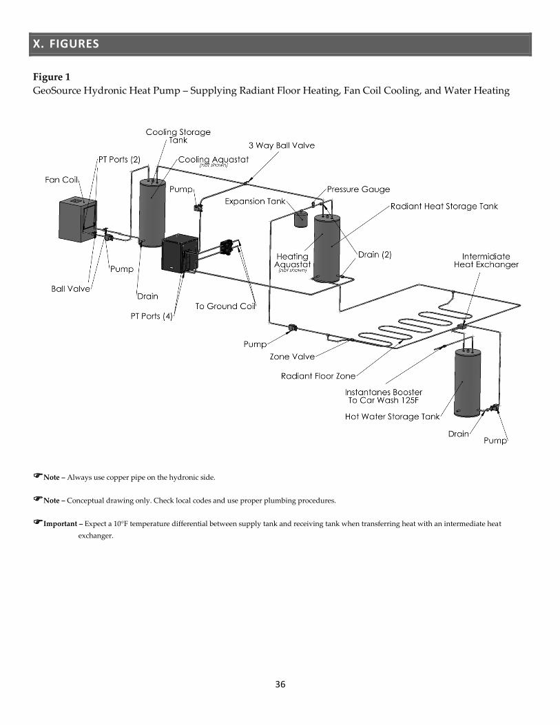
36
X. FIGURES
Figure 1
GeoSource Hydronic Heat Pump – Supplying Radiant Floor Heating, Fan Coil Cooling, and Water Heating
Note – Always use copper pipe on the hydronic side.
Note – Conceptual drawing only. Check local codes and use proper plumbing procedures.
Important – Expect a 10°F temperature differential between supply tank and receiving tank when transferring heat with an intermediate heat
exchanger.

37
Figure 2
Ground Loop Water Plumbing
Figure 3
Ground Water Plumbing
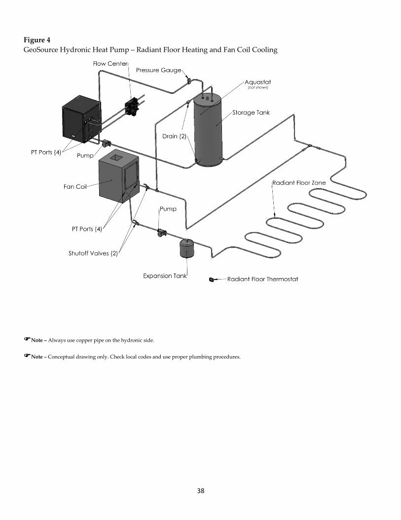
38
Figure 4
GeoSource Hydronic Heat Pump – Radiant Floor Heating and Fan Coil Cooling
Note – Always use copper pipe on the hydronic side.
Note – Conceptual drawing only. Check local codes and use proper plumbing procedures.
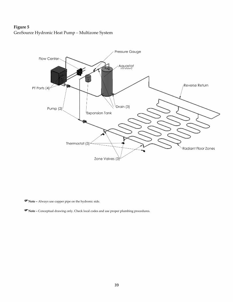
39
Figure 5
GeoSource Hydronic Heat Pump – Multizone System
Note – Always use copper pipe on the hydronic side.
Note – Conceptual drawing only. Check local codes and use proper plumbing procedures.
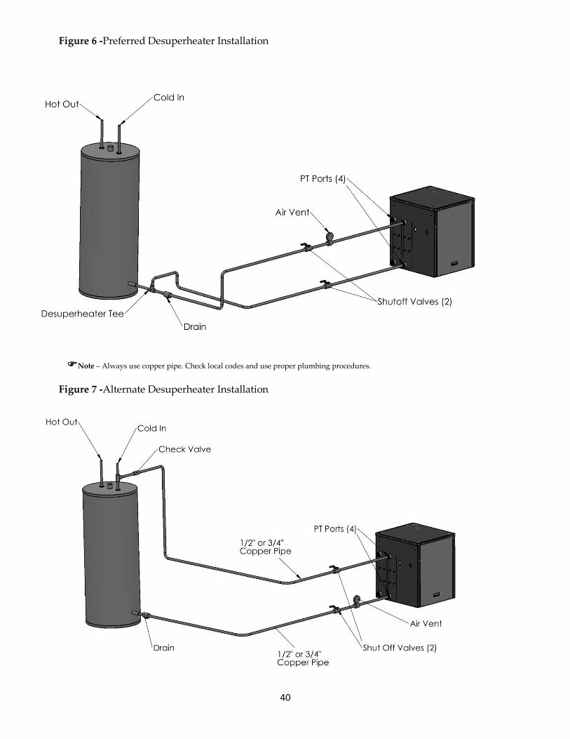
40
Figure 6 -Preferred Desuperheater Installation
Note – Always use copper pipe. Check local codes and use proper plumbing procedures.
Figure 7 -Alternate Desuperheater Installation
41
XI. TROUBLESHOOTING
If the heat pump goes into lockout on a high or low
pressure switch or discharge refrigerant
temperature, the cause of the lockout can be
narrowed down by identifying the operating mode
and which switch the unit locked out on. The
following table will help track down the problem
once this information is known.
Note – A lockout condition is a result of the heat
pump shutting itself off to protect itself, never
bypass the lockout circuit. Serious damage can be
caused by the system operating without lockout
protection and will void warranty.
Important – Always install a new filter/dryer
after replacing a refrigeration component
(compressor, etc.).
WARNING – Do not remove the desuperheater’s
high temperature cutout switch, or tank
temperatures could become dangerously high. The
desuperheater's high temperature cutout switch is
located on the return line from the water heater
and is wired in series with the desuperheater pump
to disable it from circulating at entering water
temperatures above 140°F. If the tank temperatures
become uncomfortably hot, move this switch to the
leaving water line, which will reduce the tank
maximum temperatures 10°F to 15°F.

42
CONDITION INDICATOR LIGHTS
COMMENTS PWR ASC LP HP DT
AC power applied Off Off Off Off Off Blown fuse, or power removed, or loose fuse clips.
AC power applied X X ASC indicator on for 4' 35" on power initialization.
AC power applied X Power applied - unit running or waiting for a call to run.
Run cycle complete X X ASC indicator ON for 70 to 130 seconds after compressor shutdown.
LOW PRESSURE INDICATOR
Heating or Cooling –
before Y call X X Flash
-Check if Low Pressure switch is open.
-Check electrical connections between Low Pressure switch and Controller.
Heating - during Y call X X X
-Loss/lack of flow through ground-side heat exchanger.
-Low fluid temperature operation in ground-side heat exchanger.
-Freezing fluid in ground-side heat exchanger (lack of antifreeze).
-Dirty ground-side heat exchanger (on ground water systems).
-Low ambient temperature at the heat pump.
-Undercharged / overcharged refrigerant circuit.
-Expansion valve / sensing bulb malfunction.
-Excessive low fluid temperature in hydronic-side heat exchanger.
Cooling - during Y call X X X
-Loss/lack of flow through hydronic heat exchanger.
-Low fluid temperature in the hydronic loop.
-Freezing fluid in the hydronic heat exchanger (lack of antifreeze).
-Low ambient temperature at the heat pump.
-Undercharged / overcharged refrigerant circuit.
-Expansion valve / sensing bulb malfunction.
-Excessively low fluid temperature in the ground side heat exchanger.
HIGH PRESSURE INDICATOR
Heating or Cooling –
before Y call X X
-Check if High Pressure switch is open.
-Check electrical connections between High Pressure switch and Controller.
Heating - during Y call X X X
-Loss/lack of flow through hydronic heat exchanger.
-High fluid temperature in the hydronic loop.
-Overcharged refrigerant circuit.
-Expansion valve / sensing bulb malfunction.
Cooling – during Y call X X X
-Loss/lack of flow through the ground-side heat exchanger.
-High fluid temperature in the ground-side heat exchanger.
-Dirty ground-side heat exchanger (on ground water systems).
-Overcharged refrigerant circuit.
-Expansion valve / sensing bulb malfunction.
DISCHARGE REFRIGERANT TEMPERATURE
INDICATOR (DT)
Heating or Cooling –
before Y call X X
-Check if DT switch is open.
-Check electrical connections between DT switch and Controller.
Heating - during Y call X X X
-Significantly low flow through hydronic side and/or ground-side heat
exchanger.
-Above maximum hydronic and/or below minimum ground temps.
-Significantly undercharged refrigerant circuit.
Cooling – during Y call X X X
-Significantly low flow through hydronic side and/or ground-side heat
exchanger.
-Above maximum ground and/or below minimum hydronic temps.
-Significantly undercharged refrigerant circuit.
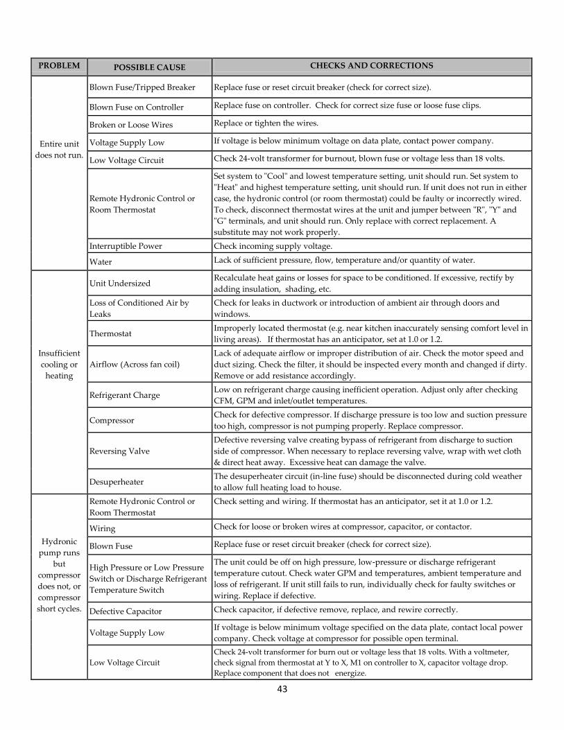
43
PROBLEM POSSIBLE CAUSE CHECKS AND CORRECTIONS
Entire unit
does not run.
Blown Fuse/Tripped Breaker Replace fuse or reset circuit breaker (check for correct size).
Blown Fuse on Controller Replace fuse on controller. Check for correct size fuse or loose fuse clips.
Broken or Loose Wires Replace or tighten the wires.
Voltage Supply Low If voltage is below minimum voltage on data plate, contact power company.
Low Voltage Circuit Check 24-volt transformer for burnout, blown fuse or voltage less than 18 volts.
Remote Hydronic Control or
Room Thermostat
Set system to "Cool" and lowest temperature setting, unit should run. Set system to
"Heat" and highest temperature setting, unit should run. If unit does not run in either
case, the hydronic control (or room thermostat) could be faulty or incorrectly wired.
To check, disconnect thermostat wires at the unit and jumper between "R", "Y" and
"G" terminals, and unit should run. Only replace with correct replacement. A
substitute may not work properly.
Interruptible Power Check incoming supply voltage.
Water Lack of sufficient pressure, flow, temperature and/or quantity of water.
Unit Undersized
Recalculate heat gains or losses for space to be conditioned. If excessive, rectify by
adding insulation, shading, etc.
Loss of Conditioned Air by
Leaks
Check for leaks in ductwork or introduction of ambient air through doors and
windows.
Thermostat
Improperly located thermostat (e.g. near kitchen inaccurately sensing comfort level in
living areas). If thermostat has an anticipator, set at 1.0 or 1.2.
Insufficient
cooling or
heating
Airflow (Across fan coil)
Lack of adequate airflow or improper distribution of air. Check the motor speed and
duct sizing. Check the filter, it should be inspected every month and changed if dirty.
Remove or add resistance accordingly.
Refrigerant Charge
Low on refrigerant charge causing inefficient operation. Adjust only after checking
CFM, GPM and inlet/outlet temperatures.
Compressor
Check for defective compressor. If discharge pressure is too low and suction pressure
too high, compressor is not pumping properly. Replace compressor.
Reversing Valve
Defective reversing valve creating bypass of refrigerant from discharge to suction
side of compressor. When necessary to replace reversing valve, wrap with wet cloth
& direct heat away. Excessive heat can damage the valve.
Desuperheater The desuperheater circuit (in-line fuse) should be disconnected during cold weather
to allow full heating load to house.
Hydronic
pump runs
but
compressor
does not, or
compressor
short cycles.
Remote Hydronic Control or
Room Thermostat
Check setting and wiring. If thermostat has an anticipator, set it at 1.0 or 1.2.
Wiring Check for loose or broken wires at compressor, capacitor, or contactor.
Blown Fuse Replace fuse or reset circuit breaker (check for correct size).
High Pressure or Low Pressure
Switch or Discharge Refrigerant
Temperature Switch
The unit could be off on high pressure, low-pressure or discharge refrigerant
temperature cutout. Check water GPM and temperatures, ambient temperature and
loss of refrigerant. If unit still fails to run, individually check for faulty switches or
wiring. Replace if defective.
Defective Capacitor Check capacitor, if defective remove, replace, and rewire correctly.
Voltage Supply Low If voltage is below minimum voltage specified on the data plate, contact local power
company. Check voltage at compressor for possible open terminal.
Low Voltage Circuit
Check 24-volt transformer for burn out or voltage less that 18 volts. With a voltmeter,
check signal from thermostat at Y to X, M1 on controller to X, capacitor voltage drop.
Replace component that does not energize.

44
PROBLEM POSSIBLE CAUSE CHECKS AND CORRECTIONS
Hydronic
pump runs
but
compressor
does not, or
compressor
short cycles.
Compressor Overload Open
In all cases an "internal" compressor overload is used. If the compressor motor is too hot,
the overload will not reset until the compressor cools down. If the compressor is cool and
the overload does not reset, there may be a defective or open overload. Replace the
compressor.
Compressor Motor Shorted to
Ground
Internal winding grounded to the compressor shell. Replace the compressor. If compressor
burnout replace the liquid line filter/drier.
Compressor Windings Open Check continuity of the compressor windings with an ohmmeter. If the windings are open,
replace the compressor.
Seized Compressor Try an auxiliary capacitor in parallel with the run capacitor momentarily. If the
compressor still does not start, replace it.
Unit short
cycles
Remote Hydronic Control or
Room Thermostat
Improperly located thermostat (e.g. near kitchen, inaccurately sensing comfort level in
living areas). If thermostat has an anticipator, set at 1.0 or 1.2.
Compressor Overload Defective compressor overload, check and replace if necessary. If the compressor runs too
hot, it may be due to insufficient refrigerant charge.
Aquastat The differential is set to close on Aquastat. Increase differential setting to 15oF.
Wiring and Controls Loose wiring connections, or control contactor defective.
Unit will not
operate in
“heating”
Thermostat Improperly Set Is it below room temperature? Check the thermostat setting.
Defective Thermostat Check thermostat operation. Replace if found defective.
Incorrect Wiring Check for broken, loose, or incorrect wires.
Aquastat set Too High Heat pump is trying to heat hot water to too hot of a temperature (over 120oF). Reduce
Aquastat set point.
Remote Hydronic Control or
Room Thermostat
Ensure that these products are properly configured according to their own instructions for
the “System Type” they are installed on.
Reversing Valve does not Shift Defective solenoid valve will not energize. Replace solenoid coil.
Unit does not
cool
(Heats Only)
Reversing Valve does not Shift,
the Valve is Stuck
The solenoid valve is de-energized due to miswiring at the unit or remote control -
correct wiring. Replace if valve is tight or frozen and will not move. Switch from heating to
cooling a few times to loosen valve.
Aquastat set Too Low Heat pump is trying to cool water too low. Increase Aquastat set point.
Insufficient Antifreeze
Water is freezing in hydronic coil. Check antifreeze level and add antifreeze to obtain
correct freeze protection.
Noisy
Operation
Compressor Make sure compressor is not in direct contact with base or sides of the cabinet. Cold
surroundings can cause liquid slugging, increase ambient temp.
Contactor
A "clattering" or "humming" noise in the contactor could be due to control voltage less
than 18 volts. Check for low supply voltage, low transformer output or extra long runs of
thermostat wires. If the contactor contacts are pitted or corroded or coil is defective, repair
or replace.
Rattles and Vibrations
Check for loose screws, panels, or internal components. Tighten and secure. Copper
piping could be hitting the metal surfaces. Carefully readjust by bending slightly. Ensu
hard plumbing is isolated from building structures.
Water and Airborne Noises Excessive water through the water-cooled heat exchanger will cause a squealing sound.
Check the water flow ensuring adequate flow for good operation but eliminating the noise.
Cavitating Pumps Purge air from ground loop or hydronic loop system.
Squealing Sound from Inside the
Cabinet
Purge air from the water side of the desuperheater heat exchanger or defective
desuperheater heat exchanger.

45
WIRING DIAGRAM RGS-W036-084
RV
R
DS
H
(Op
tio
na
l)
FU
SE
Po
we
r S
up
ply
20
8/2
40
VA
C
50
/60
Hz
HP
RV
HP
LP
DT
Re
ve
rsin
g V
alv
eH
igh
Pre
ssu
re S
witch
Dis
ch
arg
e T
he
rmo
sta
tT
1P
1T
ran
sfo
rme
r F
use
Lo
op
Pu
mp
LE
GE
ND
LP
DT
TH
ER
MO
ST
AT
10
VA
Ma
xim
um
Exte
rna
l
Co
nn
ecte
d
Lo
ad
(2
4 V
AC
)
J1
with
Ju
mp
er
–
F
orc
ed
Air M
od
e
J1
with
ou
t Ju
mp
er
–
Hyd
ron
ic M
od
e
J2
with
Ju
mp
er –
Co
nn
ects
E to
W2
J3
Byp
asse
s O
ve
rflo
w P
rote
ctio
n
Use
s O
ve
rflo
w P
rote
ctio
n
TRANSFORMER
C 208 240
BLU
YEL
24 VAC OUT
FR
EE
ZE
ST
AT
(Op
tio
na
l) 32
1
O
G
R
E
L
W2
Y
X
J3
FA
UL
T
TE
ST
W2
YE
FA
UL
T
TE
ST
T1
X R O G
M1
X
DT
LP
/FP
HP
X
F1
CO
NT
RO
L
BO
AR
D
X
J1
J2
FIE
LD
WIR
ING
FA
CT
OR
Y W
IRIN
G
S
C
R
CO
MP
RE
SS
OR
COMPRESSOR
RUN
CAPACITOR
P1
Re
lay
Hyd
ron
ic P
um
p
20
8/2
40
VA
C
1/3
HP
Ma
x
EQ
UIP
ME
NT
GR
OU
ND
HL
(Op
tio
na
l)
BLU 4
BLK 3
BL
U 5
BLU 5
YEL 13
LT BLU (When FS Used)
LT
BL
U
LT
BL
U
BL
K
BL
K
BLK
BLK
OR
G 1
BL
U 2
Lo
w P
ressu
re S
witch
Fre
eze
Pro
tectio
n S
witch
FP
DS
HD
esu
pe
rhe
ate
rJ3
YE
L
BL
U
YE
L 1
6
BL
U 1
5
BL
U 2
OR
G 1
BL
K 1
0
BL
K 1
1Y
EL
13BLU 14
BL
U 1
4B
LU
15
BL
K
RE
D
BLK
RED
GRN 12
OR
G
WH
T 9
BL
K 1
0
BLK 11
YE
L 1
6
RED 6
BLK 7
RE
D 6
BL
K 7
BL
K
BLU 8
BLU 8
BLU
RED
WHT 9
RE
D
BL
K
BL
U
LT
BL
U (
Wh
en
FS
No
t U
se
d)
BL
U 5
(W
he
n F
S U
se
d)
To
Flo
w C
en
ter
(op
tio
na
l)
No
te: T
hre
e P
ha
se
Wirin
g
L3
S
C
R
COMPRESSOR
BL
U
BL
U
BL
U
BL
K
RE
D
L1
L2
T3
T2
T1

46
WIRING DIAGRAM RGS-W120
RV
R
DS
H
(Op
tio
na
l)
FU
SE
Po
we
r S
up
ply
20
8/2
40
VA
C
50
/60
Hz
HP
RV
HP
LP
DT
Re
ve
rsin
g V
alv
eH
igh
Pre
ssu
re S
witch
Dis
ch
arg
e T
he
rmo
sta
tT
1P
1T
ran
sfo
rme
r F
use
Lo
op
Pu
mp
LE
GE
ND
LP
DT
TH
ER
MO
ST
AT
10
VA
Ma
xim
um
Exte
rna
l
Co
nn
ecte
d
Lo
ad
(2
4 V
AC
)
J1
with
Ju
mp
er
–
Fo
rce
d A
ir M
od
e
J1
with
ou
t Ju
mp
er
–
Hyd
ron
ic M
od
e
J2
with
Ju
mp
er –
Co
nn
ects
E to
W2
J3
Byp
asse
s O
ve
rflo
w P
rote
ctio
n
Use
s O
ve
rflo
w P
rote
ctio
n
PN
18
0-0
00
61
R
EV
A E
CN
13
-09
9-N
01
TRANSFORMER
C 208 240
BLU
YEL
24 VAC OUT
FR
EE
ZE
ST
AT
(Op
tio
na
l) 32
1
O
G
R
E
L
W2
Y
X
J3
FA
UL
T
TE
ST
W2
YE
FA
UL
T
TE
ST
T1
X R O G
M1
X
DT
LP
/FP
HP
X
F1
CO
NT
RO
L
BO
AR
D
X
J1
J2
FIE
LD
WIR
ING
FA
CT
OR
Y W
IRIN
G
S
C
R
CO
MP
RE
SS
OR
#1
CAP
P1
Re
lay
Hyd
ron
ic P
um
p
20
8/2
40
VA
C
1/3
HP
Ma
x
EQ
UIP
ME
NT
GR
OU
ND
HL
(Op
tio
na
l)
BLU 4
BLK 3
BL
U 5
BLU 5
YEL 13
LT BLU (When FS Used)
LT
BL
U
LT
BL
U
BL
K
BL
K
BLK
BLKO
RG
1
BL
U 2
Lo
w P
ressu
re S
witch
Fre
eze
Pro
tectio
n S
witch
FP
DS
HD
esu
pe
rhe
ate
rJ3
YE
L
BL
U
YE
L 1
6
BL
U 1
5
BL
U 2
OR
G 1
BL
K 1
0
BL
K 1
1Y
EL
13
BL
U 4
BL
U 1
5
BL
K
RE
D
BLK
RED
GRN 12
OR
G
WH
T 9
BL
K 1
0
BLK 11
YE
L 1
6
RED 6
BLK 7
RE
D 6
BL
K 7
BL
K
BL
U 8
RE
D
RE
D
BL
K
BL
U
LT
BL
U (
Wh
en
FS
No
t U
se
d)
BL
U 5
(W
he
n F
S U
se
d)
To
Flo
w C
en
ter
(op
tio
na
l) T3
T1
T2
L3
L2
L1
L3
L1
L2
T3
T2
T1
S
C
R
CO
MP
RE
SS
OR
#2
RE
D
BL
K
BL
U
S
CR
CO
MP
RE
SS
OR
#2
CAP
SC
R
CO
MP
RE
SS
OR
#1
BLK
BLK
RED
RED
BL
UB
LU
NO
TE
: S
ing
le P
ha
se
Wirin
gP
ow
er
Su
pp
ly
20
8/2
40
VA
C
50
/60
Hz
NC
NO
CO
M
T2
T1
Tim
e
De
lay
YEL
BL
U
Po
we
r
Blo
ck
Y2
Sta
rt
Assis
t
Sta
rt
Assis
t

47
Greenville, IL & Mitchell, SD
www.gogogeo.com
040-00058 Rev. G August 2013 | ©2012 Enertech Global, LLC. | All Rights Reserved


