Hynix semiconductor 1 INTRODUCTION From now on, you can hook your product onto the inter-net directly. Put the PC aside, HMS91C7432 do all the jobs that the PC do for inter-net connection. HMS91C7432 is a CMOS IC with a complete TCP/IP protocol suite to facilitate inter-net connection for embedded application. The built-in email engine can transform any ASCII message to standard email format. It sends and receives email; conduct the whole log on process automatically. Built-in PPP protocol handle user-ISP handshaking and authentication process automatically. The HMS91C7432 also includes the MODEM driver, no code should write to drive the MODEM (parameter of modem must be transferred by the host to make HMS91C7432 works with your modem). Using HMS91C7432 is easy, a simple 8 bit parallel port (8 bit data plus 4 control lines) bridge the IC with your application. A serial DTE port is ready for directly connect to an onboard modem or through DTE interface to a serial modem. Make your product inter-net able, just add an HMS91C7432 on your BOM.
Transcript
Hynix semiconductor
1
INTRODUCTION
From now on, you can hook your product onto the inter-net directly.Put the PC aside, HMS91C7432 do all the jobs that the PC do forinter-net connection.
HMS91C7432 is a CMOS IC with a complete TCP/IP protocol suite to facilitateinter-net connection for embedded application. The built-in email engine cantransform any ASCII message to standard email format. It sends and receivesemail; conduct the whole log on process automatically. Built-in PPP protocolhandle user-ISP handshaking and authentication process automatically. TheHMS91C7432 also includes the MODEM driver, no code should write to drivethe MODEM (parameter of modem must be transferred by the host to makeHMS91C7432 works with your modem).
Using HMS91C7432 is easy, a simple 8 bit parallel port (8 bit data plus 4 controllines) bridge the IC with your application. A serial DTE port is ready for directlyconnect to an onboard modem or through DTE interface to a serial modem.
Make your product inter-net able, just add an HMS91C7432 on your BOM.
Hynix semiconductor
2
HMS91C7432 features and functions
z Implementation of the complete TCP/IP protocol suitez Built-in Email sending and reception function.z Standard SMTP protocol stack.z Standard POP3 protocol stack.z Standard PPP protocol stack to facilitate dial-up network log on.z Standard DNS protocol stack, resolve URL with dynamic DNS server.z Serial modem driver built-in.z Support V.90 56Kflex modem or lower.z 8 bit parallel interface to the user application.z Serial DTE port for ease of modem interface.z 5V or 3.3V operation voltagez 20 pins SOP package
Detail description of HMS91C7432 function and its application
TCP/IP protocol suite is the key to inter-netaccess. Email; Home Page materials and allthe data traffic on the inter-net are carry outby using the TCP/IP well defined format.Time before HMS91C7432 exist, most inter-net connection were to be handled by the PC.Hand held devices and equipments must beattached to the PC to get access to theinter-net. Now the era of “PC-free” inter-netconnection has come. With HMS91C7432,you can make your product be able to sendand receive email; surf on the WWW andeven “TALK” to another device through theinter-net, by just plugging the telephone lineonto it.
The core of the HMS91C7432 is a completeTCP/IP protocol suite. Files and messagespass to the HMS91C7432 will be transformedinto the appropriate format and packets toconform the inter-net standard. Thistransformation is transparent to the user’sapplication.
On top of the TCP/IP core, there is an Emailengine built-in. User’s program just neededto inform the HMS91C7432 an email is goingto send and follow with the email body.HMS91C7432 will then wake up the modemand dial the ISP to log on the mail server. Themail will be sent when log on has success.HMS91C7432 complete this whole processfully automatic.
Reception of Email is as simple as gettingemail on the PC. The application programsend a “Receive Email” command to theHMS91C7432, it dial up the ISP and log on
the server, then it check and download anyemail automatically. Each message will bestored in the RAM buffer, HMS91C7432 willnotify the application program an email hascome and waiting for retrieve.
The built-in PPP module handles the “Log onprocess”. This is a standard protocol to passthe user’s account ID and the password tothe ISP. This module handles theauthentication and “Handshaking”. User’sprogram just pass the user’s ID andpassword to HMS91C7432 and the PPP do itall.
HMS91C7432 (later version only) also equipwith a FTP module to facilitate file transferand file downloading from the FTP site. Thisfunction is especially good for remote systemupdate and game download for hand-heldgame inter-net access.
The standard serial DTE interface on theHMS91C7432 ease the modem connection.The built-in modem driver support V.90 and56K flex dual modem or lower.
HMS91C7432 is controlled by an 8 bitdata/command port. This port acceptscommand passed by the host MCU.Incoming and outgoing message will bepassed between the host and theHMS91C7432 through this port as well.
Hynix semiconductor
3
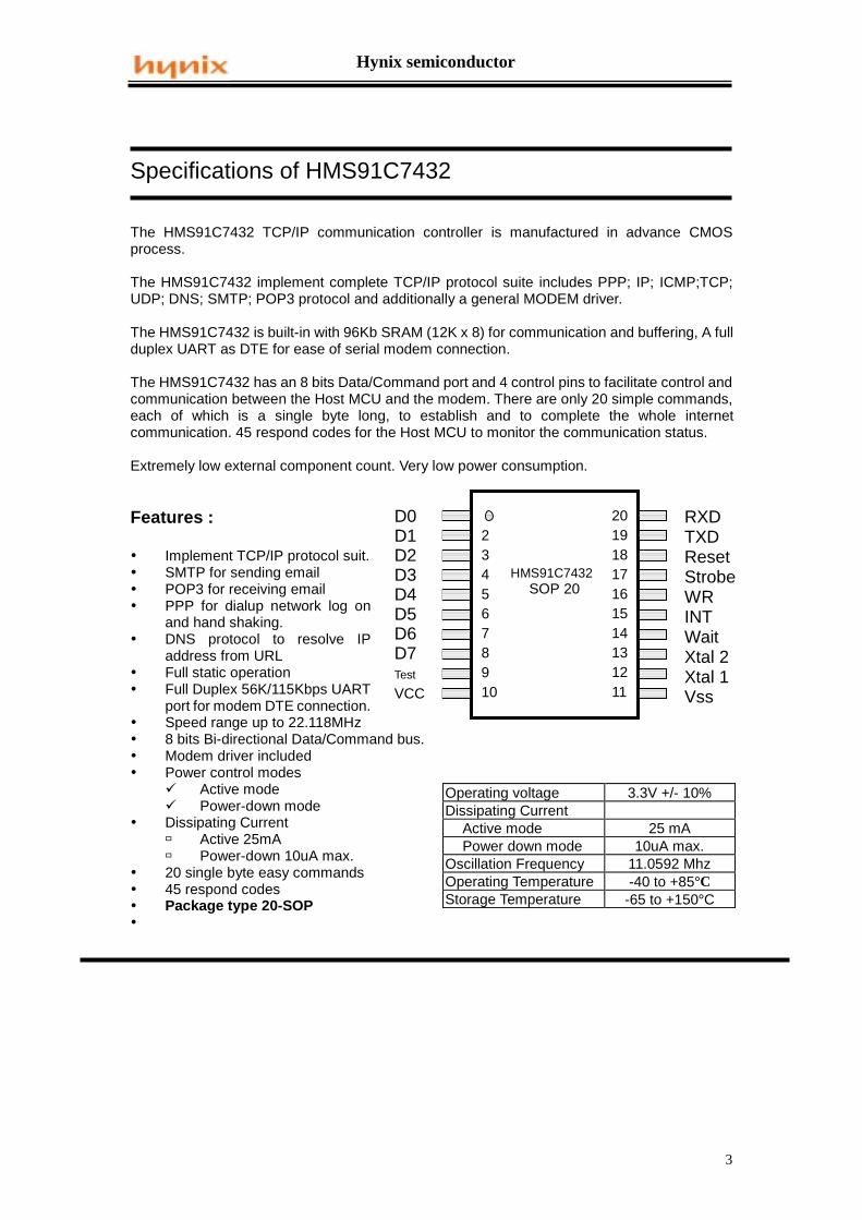
Specifications of HMS91C7432
The HMS91C7432 TCP/IP communication controller is manufactured in advance CMOSprocess.
The HMS91C7432 implement complete TCP/IP protocol suite includes PPP; IP; ICMP;TCP;UDP; DNS; SMTP; POP3 protocol and additionally a general MODEM driver.
The HMS91C7432 is built-in with 96Kb SRAM (12K x 8) for communication and buffering, A fullduplex UART as DTE for ease of serial modem connection.
The HMS91C7432 has an 8 bits Data/Command port and 4 control pins to facilitate control andcommunication between the Host MCU and the modem. There are only 20 simple commands,each of which is a single byte long, to establish and to complete the whole internetcommunication. 45 respond codes for the Host MCU to monitor the communication status.
Extremely low external component count. Very low power consumption.
Features :
y Implement TCP/IP protocol suit.y SMTP for sending emaily POP3 for receiving emaily PPP for dialup network log on
and hand shaking.y DNS protocol to resolve IP
address from URLy Full static operationy Full Duplex 56K/115Kbps UART
port for modem DTE connection.y Speed range up to 22.118MHzy 8 bits Bi-directional Data/Command bus.y Modem driver includedy Power control modes
9 Active mode9 Power-down mode
y Dissipating Currentß Active 25mAß Power-down 10uA max.
y 20 single byte easy commandsy 45 respond codesy Package type 20-SOPy
Operating voltage 3.3V +/- 10%Dissipating Current
Active mode 25 mAPower down mode 10uA max.
Oscillation Frequency 11.0592 MhzOperating Temperature -40 to +85°CStorage Temperature -65 to +150°C
D0D1D2D3D4D5D6D7Test
VCC
RXDTXDResetStrobeWRINTWaitXtal 2Xtal 1Vss
HMS91C7432SOP 20
2345678910
20191817161514131211
Hynix semiconductor
4
Specifications of HMS91C7432
MNEMONIC PIN TYPE NAME AND FUNCTIONVss 14 Ground : 0V reference.Vcc 9 Power Supply : This is the power supply voltage for
normal, and power-down operation.D0 to D7 1 – 8 I/O Data/Command Port : This is an 8 bit bi-directional I/O
port with internal pull-ups. This port is for data transferbetween Host MCU, it also serves as command receptionand responds code issuance port from and to the HostMCU.
WAIT 14 Out WAIT : Handshake signal. When low it indicates that isOK to start a cycle (assert a strobe), when high itindicates that it is OK to end the cycle (de-assert astrobe).
INT 15 Out INT : Active LOW Output a request to the Host MCU ifdata/respond code are to be sent.
WR 16 In WRITE : Active LOW write enable pin. Set this pin LOWfor a write cycle. Set this pin HIGH for a read cycle.
STROBE 17 In STROBE : Data strobe signal. Active low indicates aData_Read or Data_Write operation is in process.
RXD 20 In RXD : UART serial input port.TXD 19 Out TXD : UART serial output port.
RESET 13 In RESET : A high level on this pin for 2us while theoscillator is running resets the device.
TEST 10 In TEST : Test pin, should be stuck at zero when normaloperation.
XTAL 1 11 In XTAL1 : Input to the inverting oscillator amplifier andinput to the internal clock generator circuits.
XTAL 2 12 Out XTAL2 : Output to the inverting oscillator amplifier.
Table 1. Pin descriptions
Hynix semiconductor
5
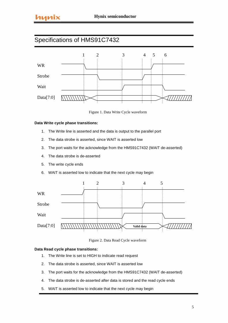
Figure 1. Data Write Cycle waveform
WR
Strobe
Wait
Data[7:0]
1 2 3 4 5 6
Valid data
Specifications of HMS91C7432
Data Write cycle phase transitions:
1. The Write line is asserted and the data is output to the parallel port
2. The data strobe is asserted, since WAIT is asserted low
3. The port waits for the acknowledge from the HMS91C7432 (WAIT de-asserted)
4. The data strobe is de-asserted
5. The write cycle ends
6. WAIT is asserted low to indicate that the next cycle may begin
Data Read cycle phase transitions:
1. The Write line is set to HIGH to indicate read request
2. The data strobe is asserted, since WAIT is asserted low
3. The port waits for the acknowledge from the HMS91C7432 (WAIT de-asserted)
4. The data strobe is de-asserted after data is stored and the read cycle ends
5. WAIT is asserted low to indicate that the next cycle may begin
ICCPower supply current : Active [email protected] Power-down mode @11.0592MHz
1610 µA
mA
-0.5 VVIL1 Input low voltage,Reset 0.2Vcc+0.1
VIH2 Input high voltage, Reset 0.6Vcc Vcc+0.5 V
IOL = 3.5mA
-10
-65
Vcc = 5V
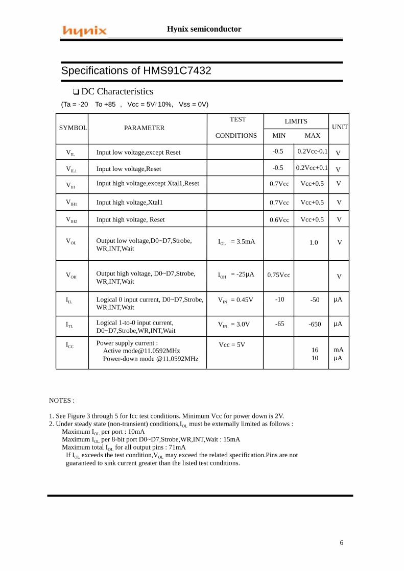
NOTES :
1. See Figure 3 through 5 for Icc test conditions. Minimum Vcc for power down is 2V. 2. Under steady state (non-transient) conditions,IOL must be externally limited as follows :
Maximum IOL per port : 10mAMaximum IOL per 8-bit port D0~D7,Strobe,WR,INT,Wait : 15mAMaximum total IOL for all output pins : 71mA
If IOL exceeds the test condition,VOL may exceed the related specification.Pins are not guaranteed to sink current greater than the listed test conditions.
0.7Vcc
Hynix semiconductor
7
Specifications of HMS91C7432
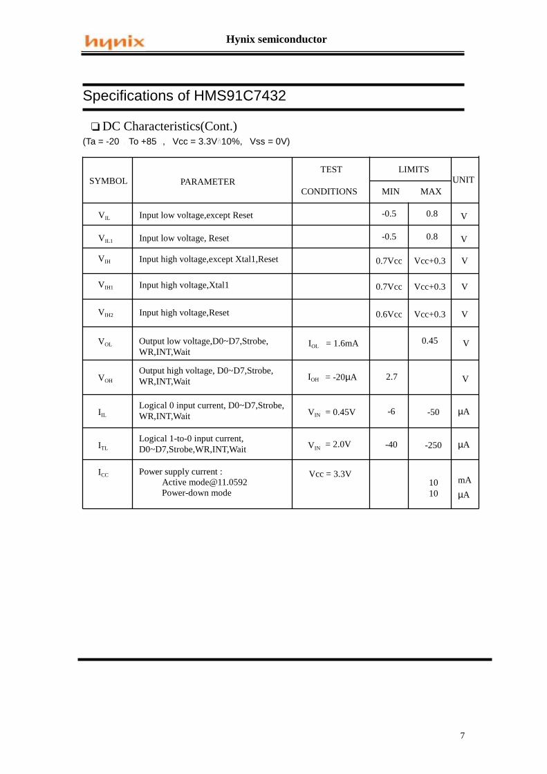
(Ta = -20 To +85 , Vcc = 3.3V 10%, Vss = 0V)
❏ DC Characteristics(Cont.)
SYMBOL PARAMETER UNITLIMITS
Vcc+0.3
-0.5
MIN MAXCONDITIONS
TEST
VVIL Input low voltage,except Reset
VIH Input high voltage,except Xtal1,Reset
0.8
0.7Vcc V
VOL Output low voltage,D0~D7,Strobe,WR,INT,Wait
0.45
VOH
Output high voltage, D0~D7,Strobe,WR,INT,Wait IOH = -20µA 2.7 V
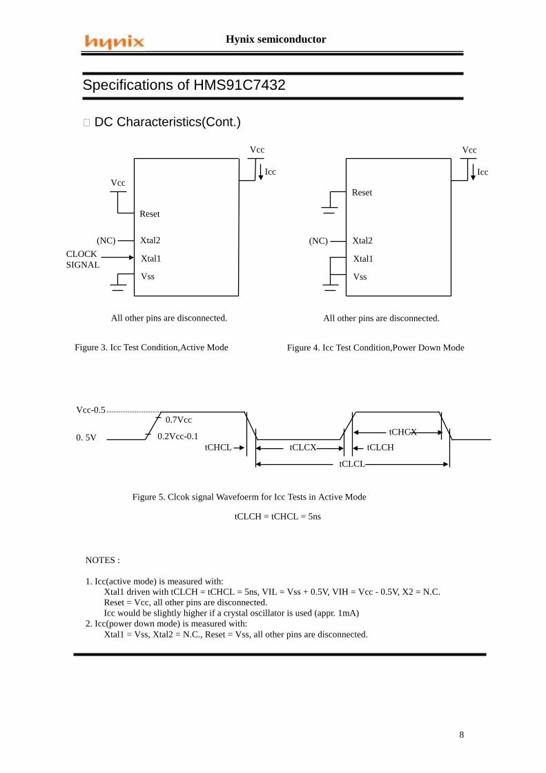
All other pins are disconnected. All other pins are disconnected.
Vcc-0.5
0. 5V
0.7Vcc
0.2Vcc-0.1tCHCL tCLCX tCLCH
tCHCX
tCLCL
Figure 5. Clcok signal Wavefoerm for Icc Tests in Active Mode
tCLCH = tCHCL = 5ns
NOTES :
1. Icc(active mode) is measured with: Xtal1 driven with tCLCH = tCHCL = 5ns, VIL = Vss + 0.5V, VIH = Vcc - 0.5V, X2 = N.C. Reset = Vcc, all other pins are disconnected. Icc would be slightly higher if a crystal oscillator is used (appr. 1mA)2. Icc(power down mode) is measured with: Xtal1 = Vss, Xtal2 = N.C., Reset = Vss, all other pins are disconnected.
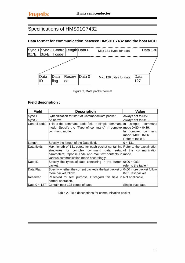
Data format for communication between HMS91C7432 and the host MCU
Sync 10x7E
Sync 20xFE
Control code
Length Data 0 Max 131 bytes for data Data 130
DataID
Dataflag
Reserved
Data 0 Max 128 bytes for data Data127
Figure 3. Data packet format
Field description :
Field Description ValueSync 1 Synconization for start of Command/Data packet. Always set to 0x7ESync 2 As above Always set to 0xFEControl code This is the command code field in simple command
mode. Specify the “Type of command” in complexcommand mode.
In simple commandmode 0x80 ~ 0x89.In complex commandmode 0x00 ~ 0x06Refer to table 3
Length Specify the length of the Data field. 0 ~ 131Data fields Max. length of 131 octets for each packet containing
structures for complex command data; setupparameters; reponse code and mail text contents invarious communication mode accordingly.
Refer to the explainationof the communicationmode.
Data ID Specify the types of data containing in the currentpacket.
0x00 ~ 0x34refer to the table 4
Data Flag Specify whether the current packet is the last packet ormore packet follow.
0x00 more packet follow0x01 last packet
Reserved Reserved for test purpose. Disregard this field innormal operation.
Not applicable
Data 0 ~ 127 Contain max 128 octets of data Single byte data
Table 2. Field descriptions for communication packet
Hynix semiconductor
11
Specifications of HMS91C7432
Table 3. Listing of Control Code
ControlCode
Description Direction
0x00 Use this control code for complex command mode and mail texttransfer. This is a bi-directional command code. HMS91C7432uses this code to pass mail’s information and mail’s body to thehost.
Bi-directionaldepending onthe Data ID
0x01 For HMS91C7432 to issue complex command to the host torequest for Line Connection Info (refer to Table 5 for Info Listing).
HMS91C7432To Host
0x02 For HMS91C7432 to issue Result Code to the host (refer to Table6 for Result Code Listing).
HMS91C7432To Host
0x03 For HMS91C7432 to issue the Connection Status to the host(refer to Table 7 for Connection Status Listing). The issuance ofthe Connection Status is in respond to the Host’s request usingControl Code 0x04 in the complex command mode.
HMS91C7432To Host
0x04 Host use this control code to request the report for ConnectionStatus. This code is to be used in Simple Command mode.
Host toHMS91C7432
0x05 Host use this control code to request the report for SMTPProcessing Status. This code is to be used in Simple CommandMode.
Host toHMS91C7432
0x06 For HMS91C7432 to issue the SMTP Processing Status (refer toTable 8 for the SMTP Status Listing). The issuance of the SMTPProcessing Status is in respond to the Host’s request usingControl Code 0x05 in the complex command mode.
HMS91C7432To Host
0x80 Initiate Modem – host’s command in Simple Command mode.Instruct the HMS91C7432 to initialize the Modem and send thepre-set AT initializing string. This command must be issued afterthe AT initializing string has been passed.
Host toHMS91C7432
0x81 Terminate – host’s command in Simple Command mode. Instructthe HMS91C7432 to terminate the current process.
Host toHMS91C7432
0x82 Log In ISP – host’s command in Simple Command mode. Instructthe HMS91C7432 to Login to the ISP. When the command isaccepted, HMS91C7432 will run the login process automaticallyand report to the host by using Control Code 0x02 complexcommand. The whole login process consists of the followingsteps, and Connection Status will be reported on each step.
1. Modem off hook2. Dial up ISP3. Modem handshake4. Logon and authentication check using PPP
The Login process ends when the authentication check is passedor in any cases a connection failure occurs.
This command must be issued after the Login information havebeen passed, otherwise, HMS91C7432 will issue request usingControl Code 0x01 for missing info.
Host toHMS91C7432
Hynix semiconductor
12
Specifications of HMS91C7432
Continue of Table 3. Listing of Control Code
0x83 Quit ISP – Host’s command in Simple Command mode. Instructthe HMS91C7432 to end the current ISP session. When thecommand is accepted, HMS91C7432 will run the Disconnectprocess automatically and report to the host by using ControlCode 0x02 complex command. The whole Disconnect processconsists of the following steps, and Connection Status will bereported on each step.
1. Quit the ISP internet connection2. Disconnect the telephone line3. Hang up the modem and modem go On Hook
The Quit process ends when the modem responds with On HookOK, or in any cases a connection failure occurs.
Host toHMS91C7432
0x84 Login SMTP Server - Host’s command in Simple Commandmode. Instruct the HMS91C7432 to login to the dedicated SMTPserver. Upon the command is accepted, HMS91C7432 will run thefollowing steps, and Connection Status will be reported on eachstep.
1. Run DNS protocol to resolve for the SMTP server’s IPaddress.
2. Register to the SMTP server.The Login SMTP process ends when the SMTP server returns anOK response code, or in any cases a Logon failure occurs.
Host toHMS91C7432
0x85 Quit SMTP Server - Host’s command in Simple Command mode.Instruct the HMS91C7432 to end the current SMTP session. Uponthe command is accepted, HMS91C7432 will quit the SMTPServer and keep ON LINE (keep connection with the internet).Quit SMTP OK will be reported to the host by using Control Code0x02 complex command.
Host toHMS91C7432
0x86 Send Mail Request - Host’s command in Simple Commandmode. Instruct the HMS91C7432 to get permission from theSMTP server for sending mail. Upon the command is accepted,HMS91C7432 will run the following steps, and Connection Statuswill be reported on each step.
1. Send the “Send Mail” request to the SMTP server2. Pass Sender email address; Recipient email address
to the SMTP server for validation.3. Wait for permission to send the mail’s body.
When the SMTP server accept all the mail info and an OK to sendis received, HMS91C7432 will issue Ready to send responseusing Control Code 0x02 to the host. DO NOT send the mail bodybefore this response is issued.
Host toHMS91C7432
Hynix semiconductor
13
Specifications of HMS91C7432
Continue of Table 3. Listing of Control Code
0x87 Login POP3 server - Host’s command in Simple Commandmode. Instruct the HMS91C7432 to login to the dedicated POP3server. Upon the command is accepted, HMS91C7432 will run thefollowing steps, and Connection Status will be reported on eachstep.
1. Run DNS protocol to resolve for the POP3 server’s IPaddress.
2. Register to the POP3 server and run the authenticationcheck process
3. If authentication check is passed, request the POP3server to return the number of mail contain in themailbox.
4. If UIDL option is set (refer to Table 4 for explanation ofUIDL option), request the POP3 server to return theLength and UID for each mail in the mailbox.
The Login POP3 process ends when the POP3 server returns thenumber of mail and or the UIDL, or in any cases a Logon failureoccurs. Upon receipt of the “Number of Mail” info and the UIDLinfo, HMS91C7432 will pass these info to the host by usingComplex Command mode with Control Code 0x00.
The Login POP3 command must be issued after the POP3 Logininformation have been passed, otherwise, HMS91C7432 willissue request using Control Code 0x01 for missing info.
Host toHMS91C7432
0x88 Quit POP3 Server - Host’s command in Simple Command mode.Instruct the HMS91C7432 to end the current POP3 session. Uponthe command is accepted, HMS91C7432 will quit the POP3Server and keep ON LINE (keep connection with the internet).Quit POP3 OK will be reported to the host by using Control Code0x02 complex command.
Host toHMS91C7432
0x89 Shut Down HMS91C7432 - Host’s command in SimpleCommand mode. Instruct the HMS91C7432 to enter the PowerDown mode. Make sure the SMTP session or the POP3 session isterminated and the line is disconnected before the Shut Downcommand is issued.
Host toHMS91C7432
Hynix semiconductor
14
Specifications of HMS91C7432
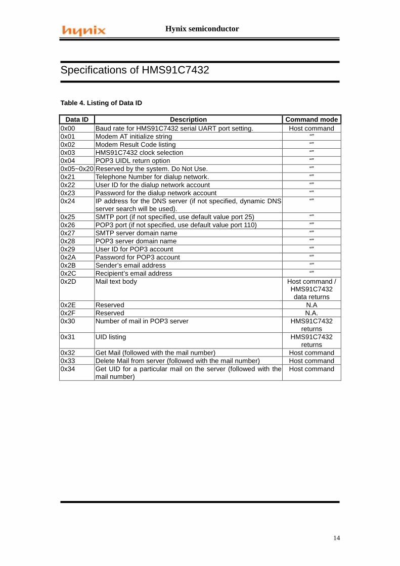
Table 4. Listing of Data ID
Data ID Description Command mode0x00 Baud rate for HMS91C7432 serial UART port setting. Host command0x01 Modem AT initialize string “”0x02 Modem Result Code listing “”0x03 HMS91C7432 clock selection “”0x04 POP3 UIDL return option “”0x05~0x20 Reserved by the system. Do Not Use. “”0x21 Telephone Number for dialup network. “”0x22 User ID for the dialup network account “”0x23 Password for the dialup network account “”0x24 IP address for the DNS server (if not specified, dynamic DNS
server search will be used).“”
0x25 SMTP port (if not specified, use default value port 25) “”0x26 POP3 port (if not specified, use default value port 110) “”0x27 SMTP server domain name “”0x28 POP3 server domain name “”0x29 User ID for POP3 account “”0x2A Password for POP3 account “”0x2B Sender’s email address “”0x2C Recipient’s email address “”0x2D Mail text body Host command /
HMS91C7432data returns
0x2E Reserved N.A0x2F Reserved N.A.0x30 Number of mail in POP3 server HMS91C7432
returns0x31 UID listing HMS91C7432
returns0x32 Get Mail (followed with the mail number) Host command0x33 Delete Mail from server (followed with the mail number) Host command0x34 Get UID for a particular mail on the server (followed with the
mail number)Host command
Hynix semiconductor
15
Specifications of HMS91C7432
Table 5. Listing of Info code for complex request mode made by HMS91C7432
Data ID DescriptionData_ID.0 Requesting Recipient’s and Sender’s email addressData_ID.1 Requesting Password for POP3 accountData_ID.2 Requesting User ID for POP3 accountData_ID.3 Requesting Domain Name for POP3 serverData_ID.4 Requesting Domain Name for SMTP serverData_ID.5 Requesting Password for dialup network accountData_ID.6 Requesting User ID for dialup network accountData_ID.7 Requesting Telephone number for dialup account
Note on use: Whenever the HMS91C7432 needs network connection info, and it is missing orcorrupted in HMS91C7432 memory, HMS91C7432 will issue a request using complexcommand mode with Control Code 0x01 following with the above Data ID for necessaryinformation return. Each bit of the Data ID, if set, indicates the co-responding info is needed.
Table 6. Listing of Response Code issued by HMS91C7432
In respond to the host’s command, the HMS91C7432 always return the following ResponseCode by using complex command mode with Control Code 0x02. The time taking to a responseis variable and mostly depending on the physical connection and the network traffic. Make surea response code is received before issuing a new command.
ResponseCode
Description Related layer andprotocol
0x40 Modem is ready Modem initialization0x41 Connected – modem is connected to the remote terminal Modem Dialup0x42 Modem not ready – modem is not presented or modem does
not return a correct responseModem initialization
0x43 No Carrier – No carrier signal is detected. Modem will hangup automatically.
Modem Dialup
0x44 Error – Modem internal error or unknown modem error. Modem Dialup0x45 No Dial tone – No dial tone is detected. Possibly the phone
line is not connected.Modem Dialup
0x46 Busy – Line is busy. Modem Dialup0x47 No answer – phone is no answer Modem Dialup0x48 Modem Hang Up – The modem is disconnected. Modem Dialup0x49 Internet Logon OK – The internet account authentication is
passed, Logon success.PPP
Hynix semiconductor
16
Specifications of HMS91C7432
Continue to Table 6. Listing of Response Code issued by HMS91C7432
0x4A ISP No Response – ISP has no response after a long timeout.
PPP
0x4B Authentication Fail – Invalid User ID or invalid password PPP0x4C Logon Fail – Unable to logon to the internet for other reason PPP0x4D Internet Quit OK – Disconnect from the internet and go Off
Line.PPP
0x4E Reserved0x4F Reserved0x50 Mail Sent OK – a mail is sent successfully SMTP0X51 SMTP Logon Fail – Fail to logon to the SMTP server SMTP0x52 Mail Received OK – A mail is received successfully POP30x53 POP3 Logon Fail – Fail to logon to the POP3 server POP30x54 POP3 Authentication Fail – Invalid POP3 User ID or invalid
POP3 passwordPOP3
0x55 Transmission Data Error – Data passed to the server is notaccepted (e.g. un-resolvable email address)
SMTP
0x56 Reception Data Error – Invalid data is received. POP30x57 NO New Mail – POP3 mail box is empty POP30x58 SMTP Logon OK – Successfully Logon to the SMTP server SMTP0x59 POP3 Logon OK – Successfully Logon to the POP3 server POP30x5A DNS Fail – Unable to locate DNS server or DNS server return
invalid dataDNS
0x5B SMTP Quit – Exit SMTP server SMTP0x5C POP3 Quit – Exit POP3 server POP30x5D Mail Deleted – A mail is deleted from the POP3 mail box POP30x5E Mail Deleted Fail – Unable to delete the mail, either the mail
number is not exist or the mail is locked by the serverPOP3
0x5F Wrong Mail Number – The mail number not exist in themailbox.
POP3
0x60 SMTP Ready to Send – HMS91C7432 is ready to acceptnext packet of the mail text body.
SMTP
0x61 SMTP Buffer Overflow – HMS91C7432 outgoing buffer isfull. Last packet received is invalid. Host must resend theprevious packet.
SMTP
0x62 SMTP Buffer full – HMS91C7432 outgoing buffer is nearlyfull and can not accept more data. The last packet isaccepted.
SMTP
Hynix semiconductor
17
Specifications of HMS91C7432
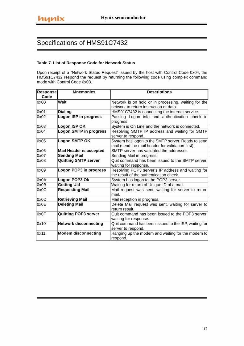
Table 7. List of Response Code for Network Status
Upon receipt of a “Network Status Request” issued by the host with Control Code 0x04, theHMS91C7432 respond the request by returning the following code using complex commandmode with Control Code 0x03.
ResponseCode
Mnemonics Descriptions
0x00 Wait Network is on hold or in processing, waiting for thenetwork to return instruction or data.
0x01 Dialing HMS91C7432 is connecting the internet service.0x02 Logon ISP in progress Passing Logon info and authentication check in
progress0x03 Logon ISP OK System is On Line and the network is connected.0x04 Logon SMTP in progress Resolving SMTP IP address and waiting for SMTP
server to respond.0x05 Logon SMTP OK System has logon to the SMTP server. Ready to send
mail (send the mail header for validation first).0x06 Mail Header is accepted SMTP server has validated the addresses0x07 Sending Mail Sending Mail in progress0x08 Quitting SMTP server Quit command has been issued to the SMTP server,
waiting for response.0x09 Logon POP3 in progress Resolving POP3 server’s IP address and waiting for
the result of the authentication check.0x0A Logon POP3 Ok System has logon to the POP3 server.0x0B Getting Uid Waiting for return of Unique ID of a mail.0x0C Requesting Mail Mail request was sent, waiting for server to return
mail.0x0D Retrieving Mail Mail reception in progress.0x0E Deleting Mail Delete Mail request was sent, waiting for server to
return result.0x0F Quitting POP3 server Quit command has been issued to the POP3 server,
waiting for response.0x10 Network disconnecting Quit command has been issued to the ISP, waiting for
server to respond.0x11 Modem disconnecting Hanging up the modem and waiting for the modem to
respond.
Hynix semiconductor
18
Specifications of HMS91C7432
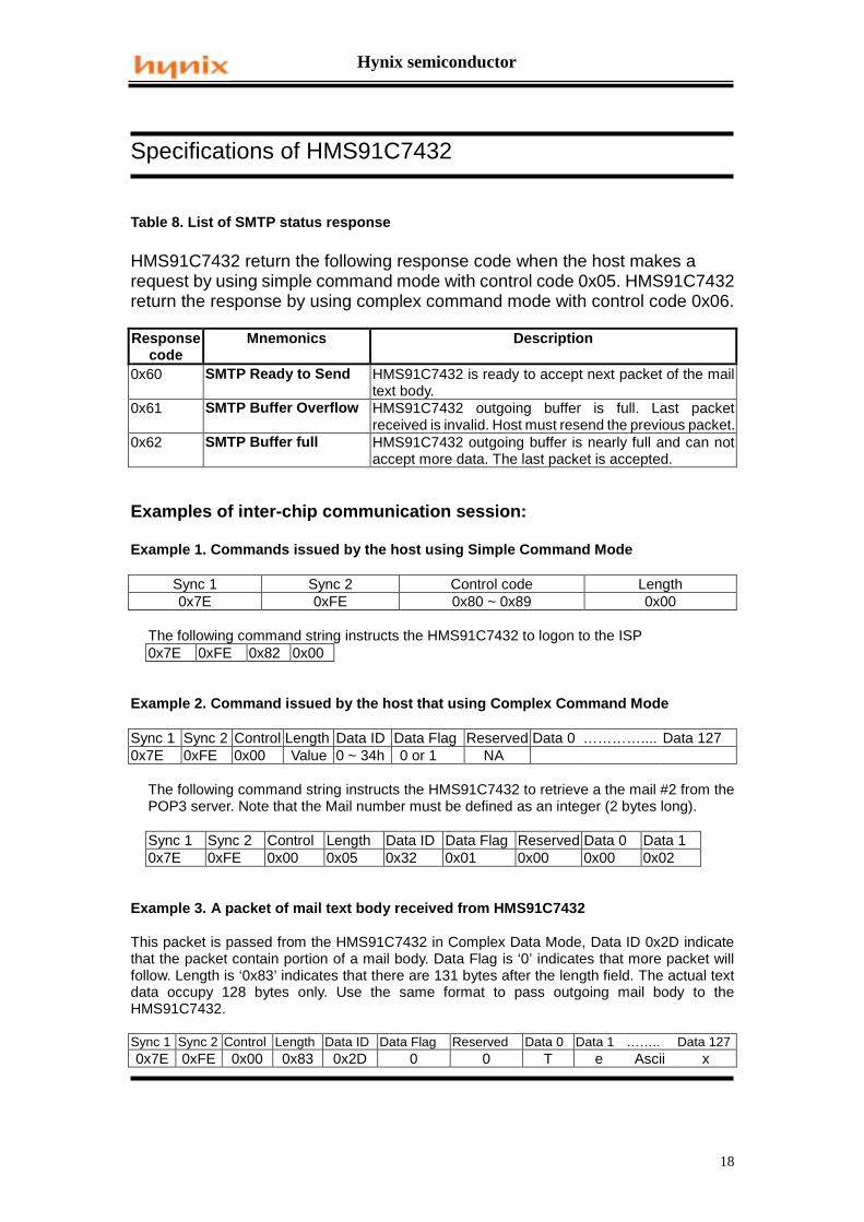
Table 8. List of SMTP status response
HMS91C7432 return the following response code when the host makes arequest by using simple command mode with control code 0x05. HMS91C7432return the response by using complex command mode with control code 0x06.
Responsecode
Mnemonics Description
0x60 SMTP Ready to Send HMS91C7432 is ready to accept next packet of the mailtext body.
0x61 SMTP Buffer Overflow HMS91C7432 outgoing buffer is full. Last packetreceived is invalid. Host must resend the previous packet.
0x62 SMTP Buffer full HMS91C7432 outgoing buffer is nearly full and can notaccept more data. The last packet is accepted.
Examples of inter-chip communication session:
Example 1. Commands issued by the host using Simple Command Mode
The following command string instructs the HMS91C7432 to logon to the ISP0x7E 0xFE 0x82 0x00
Example 2. Command issued by the host that using Complex Command Mode
Sync 1 Sync 2 Control Length Data ID Data Flag Reserved Data 0 ………….... Data 1270x7E 0xFE 0x00 Value 0 ~ 34h 0 or 1 NA
The following command string instructs the HMS91C7432 to retrieve a the mail #2 from thePOP3 server. Note that the Mail number must be defined as an integer (2 bytes long).
Sync 1 Sync 2 Control Length Data ID Data Flag Reserved Data 0 Data 10x7E 0xFE 0x00 0x05 0x32 0x01 0x00 0x00 0x02
Example 3. A packet of mail text body received from HMS91C7432
This packet is passed from the HMS91C7432 in Complex Data Mode, Data ID 0x2D indicatethat the packet contain portion of a mail body. Data Flag is ‘0’ indicates that more packet willfollow. Length is ‘0x83’ indicates that there are 131 bytes after the length field. The actual textdata occupy 128 bytes only. Use the same format to pass outgoing mail body to theHMS91C7432.
Sync 1 Sync 2 Control Length Data ID Data Flag Reserved Data 0 Data 1 …….. Data 1270x7E 0xFE 0x00 0x83 0x2D 0 0 T e Ascii x
Hynix semiconductor
19
Specifications of HMS91C7432
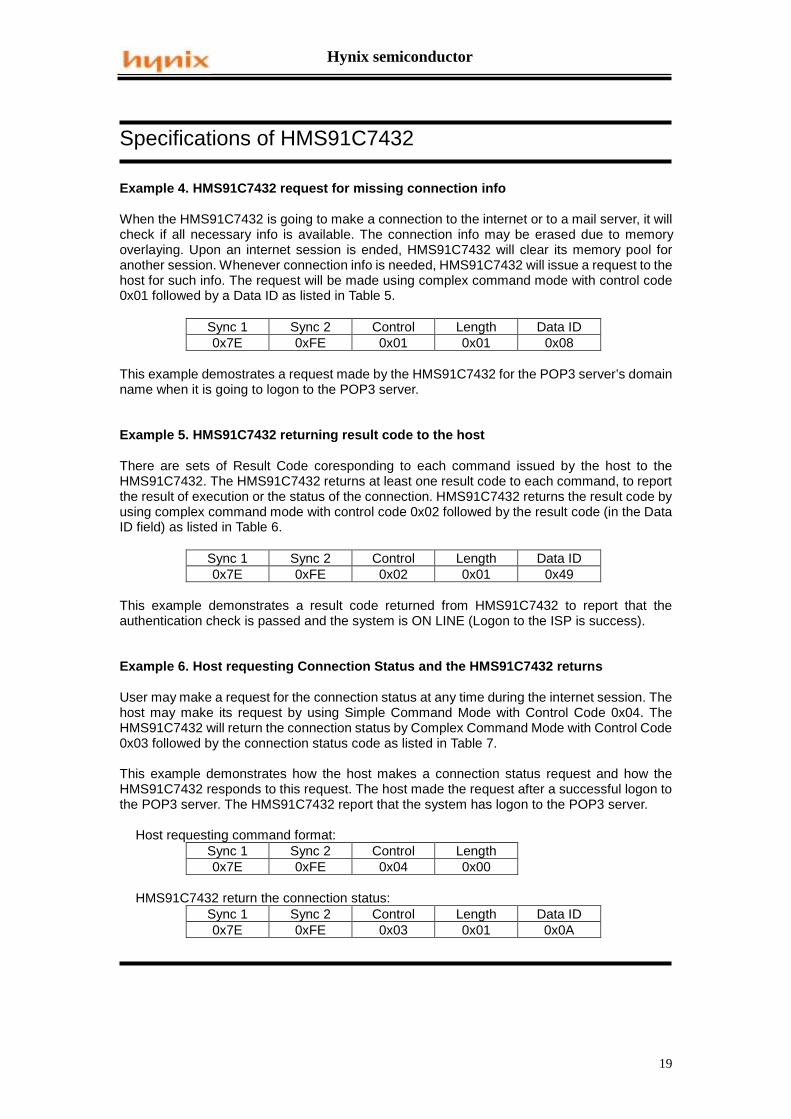
Example 4. HMS91C7432 request for missing connection info
When the HMS91C7432 is going to make a connection to the internet or to a mail server, it willcheck if all necessary info is available. The connection info may be erased due to memoryoverlaying. Upon an internet session is ended, HMS91C7432 will clear its memory pool foranother session. Whenever connection info is needed, HMS91C7432 will issue a request to thehost for such info. The request will be made using complex command mode with control code0x01 followed by a Data ID as listed in Table 5.
Sync 1 Sync 2 Control Length Data ID0x7E 0xFE 0x01 0x01 0x08
This example demostrates a request made by the HMS91C7432 for the POP3 server’s domainname when it is going to logon to the POP3 server.
Example 5. HMS91C7432 returning result code to the host
There are sets of Result Code coresponding to each command issued by the host to theHMS91C7432. The HMS91C7432 returns at least one result code to each command, to reportthe result of execution or the status of the connection. HMS91C7432 returns the result code byusing complex command mode with control code 0x02 followed by the result code (in the DataID field) as listed in Table 6.
Sync 1 Sync 2 Control Length Data ID0x7E 0xFE 0x02 0x01 0x49
This example demonstrates a result code returned from HMS91C7432 to report that theauthentication check is passed and the system is ON LINE (Logon to the ISP is success).
Example 6. Host requesting Connection Status and the HMS91C7432 returns
User may make a request for the connection status at any time during the internet session. Thehost may make its request by using Simple Command Mode with Control Code 0x04. TheHMS91C7432 will return the connection status by Complex Command Mode with Control Code0x03 followed by the connection status code as listed in Table 7.
This example demonstrates how the host makes a connection status request and how theHMS91C7432 responds to this request. The host made the request after a successful logon tothe POP3 server. The HMS91C7432 report that the system has logon to the POP3 server.
HMS91C7432 return the connection status:Sync 1 Sync 2 Control Length Data ID0x7E 0xFE 0x03 0x01 0x0A
Hynix semiconductor
20
Specifications of HMS91C7432
Example 7. Host requesting SMTP Connection Status and the HMS91C7432 returns
When sending out an email during SMTP session, the host should know when can it pass themail header and when can it pass the mail body to the HMS91C7432. Usually, depending on thetraffic of the network, it takes a longer time to be successfully logon to the SMTP server. Thehost should frequently check the connection status to determine the time to pass the mailheader or to determine when to terminate the logon process if a time out is up. The host maymake such a report by using Simple Command Mode with Control Code 0x05. TheHMS91C7432 will return the SMTP connection status by Complex Command Mode with ControlCode 0x06 followed with the SMTP status code as listed in Table 8.
This example demonstrates how the host makes a SMTP connection status request and howthe HMS91C7432 responds to this request. The host made the request after a successful logonto the SMTP server. The HMS91C7432 report that it is ready to accept the mail body. If therequest is made during the mail sending session, the following connection status indicates theHMS91C7432 is ready to accept more packets (Outgoing buffer is not full).
HMS91C7432 return the connection status:Sync 1 Sync 2 Control Length Data ID0x7E 0xFE 0x06 0x01 0x60
Hynix semiconductor
21
Specifications of HMS91C7432
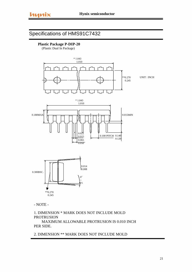
Plastic Package P-DIP-20 (Plastic Dual In Package)
UNIT : INCH
* 1.043 1.010
* 1.043 1.010
0.180MAX
0.100 PITCH 0.1400.120
0.0210.015
**0.270 0.245
0.0650.050
0.015MIN
0.0140.008
0�~15
0.300BSC.
**0.270 0.245
- NOTE -
1. DIMENSION * MARK DOES NOT INCLUDE MOLDPROTRUSION MAXIMUM ALLOWABLE PROTRUSION IS 0.010 INCHPER SIDE.
2. DIMENSION ** MARK DOES NOT INCLUDE MOLD
Hynix semiconductor
22
Specifications of HMS91C7432
Plastic Package P-SOP-20 (Plastic Small Outline Package)
UNIT : INCH
0.4190.398
* 0.5118 0.4961
0.0200.0130.050 PITCH
0.1040.093
0.01180.004
* 0.5118 0.4961
0.01250.0091
0.0420.016
**0.299 0.291
* *0.299 0.291
- NOTE -1. DIMENSION * MARK DOES NOT INCLUDE MOLD PROTRUSION MAXIMUM ALLOWABLE PROTRUSION IS 0.006 INCH PER SIDE.2. DIMENSION ** MARK DOES NOT INCLUDE MOLD PROTRUSION MAXIMUM ALLOWABLE PROTRUSION IS 0.010 INCH PER SIDE.3. DIMENSIONING AND TOLERANCING PER ANSI Y14.5M-1982
Hynix semiconductor
23
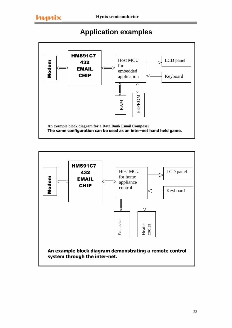
Application examples
0RGHP
+06<4&:765(0$,/&+,3
Host MCUforembeddedapplication
LCD panel
Keyboard
RA
M
EE
PR
OM
An example block diagram for a Data Bank Email Composer������������ ��������������������������������������� ����