MOTHER THERESSA ENGINEERING COLLEGE Paper presentation On the topic Hyper-Threading Team members:-M.Rohit Reddy Pankesh kumarContact Email id: - [email protected][email protected]PHONE NUMBERS:-9989191318
ways to improve performance at a greater rate than transistor counts and power
dissipation. Intel’s Hyper-Threading Technology is one solution.
Processor Microarchitecture
Traditional approaches to processor design have focused on higher clock speeds,
instruction-level parallelism (ILP), and caches. Techniques to achieve higher clock
speeds involve pipelining the microarchitecture to finer granularities, also called super-
pipelining. Higher clock frequencies can greatly improve performance by increasing the
number of instructions that can be executed each second. Because there will be far more
instructions in-flight in a superpipelined microarchitecture, handling of events that
disrupt the pipeline, e.g., cache misses, interrupts and branch mispredictions, can be
costly.
ILP refers to techniques to increase the number of instructions executed each
clock cycle. For example, a super-scalar processor has multiple parallel execution units
that can process instructions simultaneously. With super-scalar execution, several
instructions can be executed each clock cycle. However, with simple inorder execution, itis not enough to simply have multiple execution units. The challenge is to find enough
instructions to execute. One technique is out-of-order execution where a large window of
instructions is simultaneously evaluated and sent to execution units, based on instruction
dependencies rather than program order.
The vast majority of techniques to improve processor performance from one
generation to the next is complex and often adds significant die-size and power costs.
These techniques increase performance but not with 100% efficiency; i.e., doubling the
number of execution units in a processor does not double the performance of the
processor, due to limited parallelism in instruction flows. Similarly, simply doubling the
processing and Web services have an abundance of software threads that can be executed
simultaneously for faster performance. Even desktop applications are becoming
increasingly parallel. Intel architects have been trying to leverage this so-called thread-
level parallelism (TLP) to gain a better performance vs. transistor count and power ratio.
Finally, there is simultaneous multi-threading, where multiple threads can execute
on a single processor without switching. The threads execute simultaneously and make
much better use of the resources. This approach makes the most effective use of
processor resources: it maximizes the performance vs. transistor count and power
consumption. Hyper-Threading Technology brings the simultaneous multi-threading
approach to the Intel architecture. In this paper we discuss the architecture and the first
implementation of Hyper-Threading Technology on the Intel Xeon processor family.
HYPER-THREADING TECHNOLOGY
ARCHITECTURE
Hyper-Threading Technology makes a single physical processor appear as multiple
logical processors [11, 12]. To do this, there is one copy of the architecture state for each
logical processor, and the logical processors share a single set of physical execution
resources. From a software or architecture perspective, this means operating systems anduser programs can schedule processes or threads to logical processors as they would on
conventional physical processors in a multiprocessor system. From a microarchitecture
perspective, this means that instructions from logical processors will persist and executesimultaneously on shared execution resources.
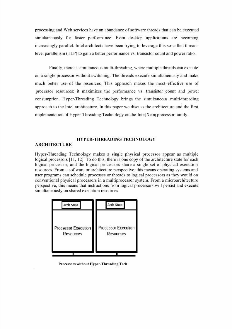
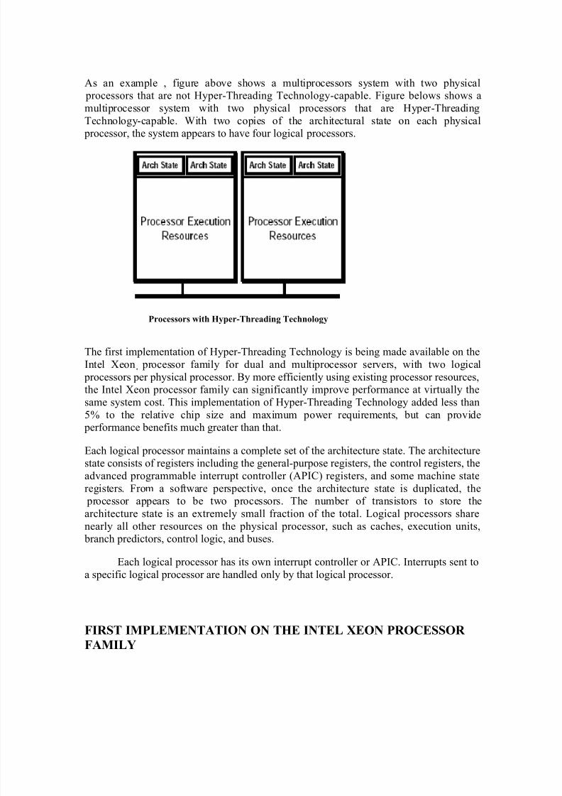
As an example , figure above shows a multiprocessors system with two physical processors that are not Hyper-Threading Technology-capable. Figure belows shows a
multiprocessor system with two physical processors that are Hyper-Threading
Technology-capable. With two copies of the architectural state on each physical processor, the system appears to have four logical processors.
Processors with Hyper-Threading Technology
The first implementation of Hyper-Threading Technology is being made available on the
Intel Xeon processor family for dual and multiprocessor servers, with two logical
processors per physical processor. By more efficiently using existing processor resources,the Intel Xeon processor family can significantly improve performance at virtually the
same system cost. This implementation of Hyper-Threading Technology added less than
5% to the relative chip size and maximum power requirements, but can provide performance benefits much greater than that.
Each logical processor maintains a complete set of the architecture state. The architecturestate consists of registers including the general-purpose registers, the control registers, the
advanced programmable interrupt controller (APIC) registers, and some machine state
registers. From a software perspective, once the architecture state is duplicated, the processor appears to be two processors. The number of transistors to store the
architecture state is an extremely small fraction of the total. Logical processors share
nearly all other resources on the physical processor, such as caches, execution units, branch predictors, control logic, and buses.
Each logical processor has its own interrupt controller or APIC. Interrupts sent toa specific logical processor are handled only by that logical processor.
Several goals were at the heart of the microarchitecture design choices made for
the Intel Xeon processor MP implementation of Hyper-Threading Technology. Onegoal was to minimize the die area cost of implementing Hyper-Threading Technology.
Since the logical processors share the vast majority of microarchitecture resources and
only a few small structures were replicated, the die area cost of the first implementationwas less than 5% of the total die area.
A second goal was to ensure that when one logical processor is stalled the other
logical processor could continue to make forward progress. A logical processor may betemporarily stalled for a variety of reasons, including servicing cache misses, handling
branch mispredictions, or waiting for the results of previous instructions. Independent
forward progress was ensured by managing buffering queues such that no logical processor can use all the entries when two active software threads2 were executing. This
is accomplished by either partitioning or limiting the number of active entries each thread
can have.
A third goal was to allow a processor running only one active software thread to
run at the same speed on a processor with Hyper-Threading Technology as on a processor without this capability. This means that partitioned resources should be recombined when
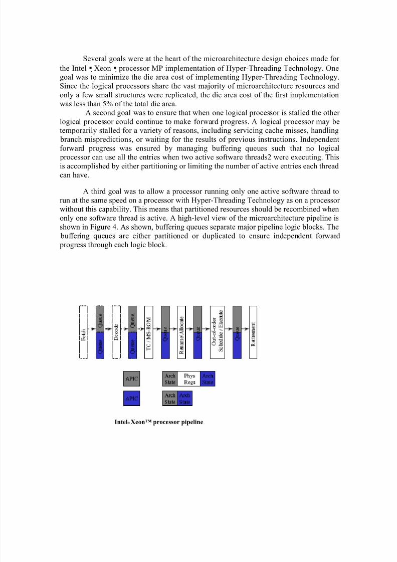
only one software thread is active. A high-level view of the microarchitecture pipeline is
shown in Figure 4. As shown, buffering queues separate major pipeline logic blocks. The
buffering queues are either partitioned or duplicated to ensure independent forward progress through each logic block.
In the following sections we will walk through the pipeline, discuss the implementation
of major functions, and detail several ways resources are shared or replicated.
FRONT END
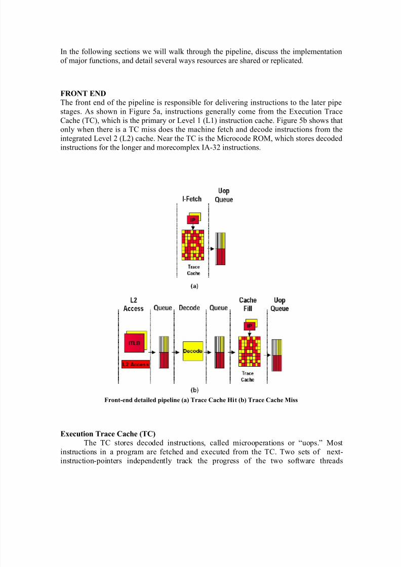
The front end of the pipeline is responsible for delivering instructions to the later pipe
stages. As shown in Figure 5a, instructions generally come from the Execution Trace
Cache (TC), which is the primary or Level 1 (L1) instruction cache. Figure 5b shows thatonly when there is a TC miss does the machine fetch and decode instructions from the
integrated Level 2 (L2) cache. Near the TC is the Microcode ROM, which stores decoded
instructions for the longer and morecomplex IA-32 instructions.
Front-end detailed pipeline (a) Trace Cache Hit (b) Trace Cache Miss
Execution Trace Cache (TC)
The TC stores decoded instructions, called microoperations or “uops.” Most
instructions in a program are fetched and executed from the TC. Two sets of next-instruction-pointers independently track the progress of the two software threads
executing. The two logical processors arbitrate access to the TC every clock cycle. If both
logical processors want access to
the TC at the same time, access is granted to one then the other in alternating clock cycles. For example, if one cycle is used to fetch a line for one logical processor, the next
cycle would be used to fetch a line for the other logical processor, provided that both
logical processors requested access to the trace cache. If one logical processor is stalledor is unable to use the TC, the other logical processor can use the full bandwidth of the
trace cache, every cycle.
The TC entries are tagged with thread information and are dynamically allocated
as needed. The TC is 8-way set associative, and entries are replaced based on a
leastrecently- used (LRU) algorithm that is based on the full 8 ways. The shared nature of the TC allows one logicalprocessor to have more entries than the other if needed.
Microcode ROM
When a complex instruction is encountered, the TC sends a microcode-instruction pointer to the Microcode ROM. The Microcode ROM controller then fetches the uops needed
and returns control to the TC. Two microcode instruction pointers are used to control the
flows independently if both logical processors are executing complex IA-32 instructions.Both logical processors share the Microcode ROM entries. Access to the Microcode
ROM alternates between logical processors just as in the TC.
ITLB and Branch Prediction
If there is a TC miss, then instruction bytes need to be fetched from the L2 cacheand decoded into uops to be placed in the TC. The Instruction Translation Lookaside
Buffer (ITLB) receives the request from the TC to deliver new instructions, and ittranslates the next-instruction pointer address to a physical address. A request is sent to
the L2 cache, and instruction bytes are returned. These bytes are placed into streaming
buffers, which hold the bytes until they can be decoded.
The ITLBs are duplicated. Each logical processor has its own ITLB and its ownset of instruction pointers to track the progress of instruction fetch for the two logical
processors. The instruction fetch logic in charge of sending requests to the L2 cache
arbitrates on a first-come first-served basis, while always reserving at least one request
slot for each logical processor. In this way, both logical processors can have fetches pending simultaneously.
The branch prediction structures are either duplicated or shared. The return stack buffer, which predicts the target of return instructions, is duplicated because it is a very
small structure and the call/return pairs are better predicted for software threads
independently. The branch history buffer used to look up the global history array is also
tracked independently for each logical processor. However, the large global history array
is a shared structure with entries that are tagged with a logical processor ID.
HYPER-THREADING EXECUTION .
The out-of-order execution engine consists of the allocation, register renaming,scheduling, and execution functions, as shown in Figure 6. This part of the machine re-
orders instructions and executes them as quickly as their inputs are ready, without regard
to the original program order.
Register Rename
The register rename logic renames the architectural IA- 32 registers onto the
machine’s physical registers. This allows the 8 general-use IA-32 integer registers to bedynamically expanded to use the available 128 physical registers. The renaming logic
uses a Register Alias Table (RAT) to track the latest version of each architectural register
to tell the next instruction(s) here to get its input operands.Since each logical processor must maintain and track its own omplete
architecture state, there are two RATs, one for each logical processor. The register
renaming process is done in parallel to the allocator logic described above, so the register
rename logic works onthe same uops to which the allocator is assigning resources.
Once uops have completed the allocation and register rename processes, they are placed
into two sets of queues, one for memory operations (loads and stores) and another for all
other operations. The two sets of queues are called the memory instruction queue and thegeneral instruction queue, respectively. The two sets of queues are also partitioned such
that uops from each logical processor can use at most half the entries.
Instruction Scheduling
The schedulers are at the heart of the out-of-order execution engine. Five uop
schedulers are used to schedule different types of uops for the various execution units.Collectively, they can dispatch up to six uops each clock cycle. The schedulers determine
when uops are ready to execute based on the readiness of their dependent input register
operands and the availability of the execution unit resources.The memory instruction queue and general instruction queues send uops to thefive scheduler queues as fast as they can, alternating between uops for the two logical
processors every clock cycle, as needed.
Each scheduler has its own scheduler queue of eight to twelve entries from whichit selects uops to send to the execution units. The schedulers choose uops regardless of
whether they belong to one logical processor or the other. The schedulers are effectively
oblivious to logical processor distinctions. The uops are simply evaluated based on
dependent inputs and availability of execution resources. For example, the schedulers
could dispatch two uops from one logical processor and two uops from the other logical
processor in the same clock cycle. To avoid deadlock and ensure fairness, there is a limiton the number of active entries that a logical processor can have in each scheduler’s
queue. This limit is dependent on the size of the scheduler queue.
Execution Units
The execution core and memory hierarchy are also largely oblivious to logical processors. Since the source and destination registers were renamed earlier to physical
registers in a shared physical register pool, uops merely access the physical register file to
get their destinations, and they write results back to the physical register file. Comparing
physical register numbers enables the forwarding logic to forward results to other executing uops without having to understand logical processors.
After execution, the uops are placed in the re-order buffer. The re-order buffer
decouples the execution stage from the retirement stage. The re-order buffer is partitioned
such that each logical processor can use half the entries.
Retirement
Uop retirement logic commits the architecture state in program order. Theretirement logic tracks when uops from the two logical processors are ready to be retired,
then retires the uops in program order for each logical processor by alternating between
the two logical processors. Retirement logic will retire uops for one logical processor,then the other, alternating back and forth. If one logical processor is not ready to retire
any uops then all retirement bandwidth is dedicated to the other logical processor.
Once stores have retired, the store data needs to be written into the level-one datacache. Selection logic alternates between the two logical processors to commit store data
to the cache.
MEMORY SUBSYSTEM
The memory subsystem includes the DTLB, the lowlatency Level 1 (L1) data
cache, the Level 2 (L2) unified cache, and the Level 3 unified cache (the Level 3 cache is
only available on the Intel Xeon processor MP). Access to the memory subsystem isalso largely oblivious to logical processors. The schedulers send load or store uops
without regard to logical processors and the memory subsystem handles them as theycome.
SINGLE-TASK AND MULTI-TASK MODES
To optimize performance when there is one software thread to execute, there aretwo modes of operation referred to as single-task (ST) or multi-task (MT). In MT-mode,
there are two active logical processors and some of the resources are partitioned as
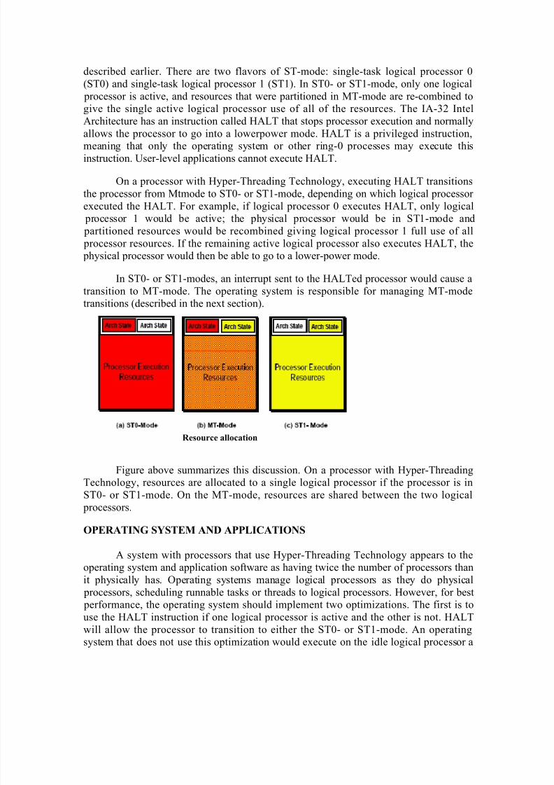
described earlier. There are two flavors of ST-mode: single-task logical processor 0
(ST0) and single-task logical processor 1 (ST1). In ST0- or ST1-mode, only one logical
processor is active, and resources that were partitioned in MT-mode are re-combined togive the single active logical processor use of all of the resources. The IA-32 Intel
Architecture has an instruction called HALT that stops processor execution and normally
allows the processor to go into a lowerpower mode. HALT is a privileged instruction,meaning that only the operating system or other ring-0 processes may execute this
On a processor with Hyper-Threading Technology, executing HALT transitions
the processor from Mtmode to ST0- or ST1-mode, depending on which logical processor
executed the HALT. For example, if logical processor 0 executes HALT, only logical processor 1 would be active; the physical processor would be in ST1-mode and
partitioned resources would be recombined giving logical processor 1 full use of all
processor resources. If the remaining active logical processor also executes HALT, the physical processor would then be able to go to a lower-power mode.
In ST0- or ST1-modes, an interrupt sent to the HALTed processor would cause atransition to MT-mode. The operating system is responsible for managing MT-modetransitions (described in the next section).
Resource allocation
Figure above summarizes this discussion. On a processor with Hyper-ThreadingTechnology, resources are allocated to a single logical processor if the processor is in
ST0- or ST1-mode. On the MT-mode, resources are shared between the two logical
processors.
OPERATING SYSTEM AND APPLICATIONS
A system with processors that use Hyper-Threading Technology appears to theoperating system and application software as having twice the number of processors than
it physically has. Operating systems manage logical processors as they do physical
processors, scheduling runnable tasks or threads to logical processors. However, for best performance, the operating system should implement two optimizations. The first is to
use the HALT instruction if one logical processor is active and the other is not. HALT
will allow the processor to transition to either the ST0- or ST1-mode. An operatingsystem that does not use this optimization would execute on the idle logical processor a
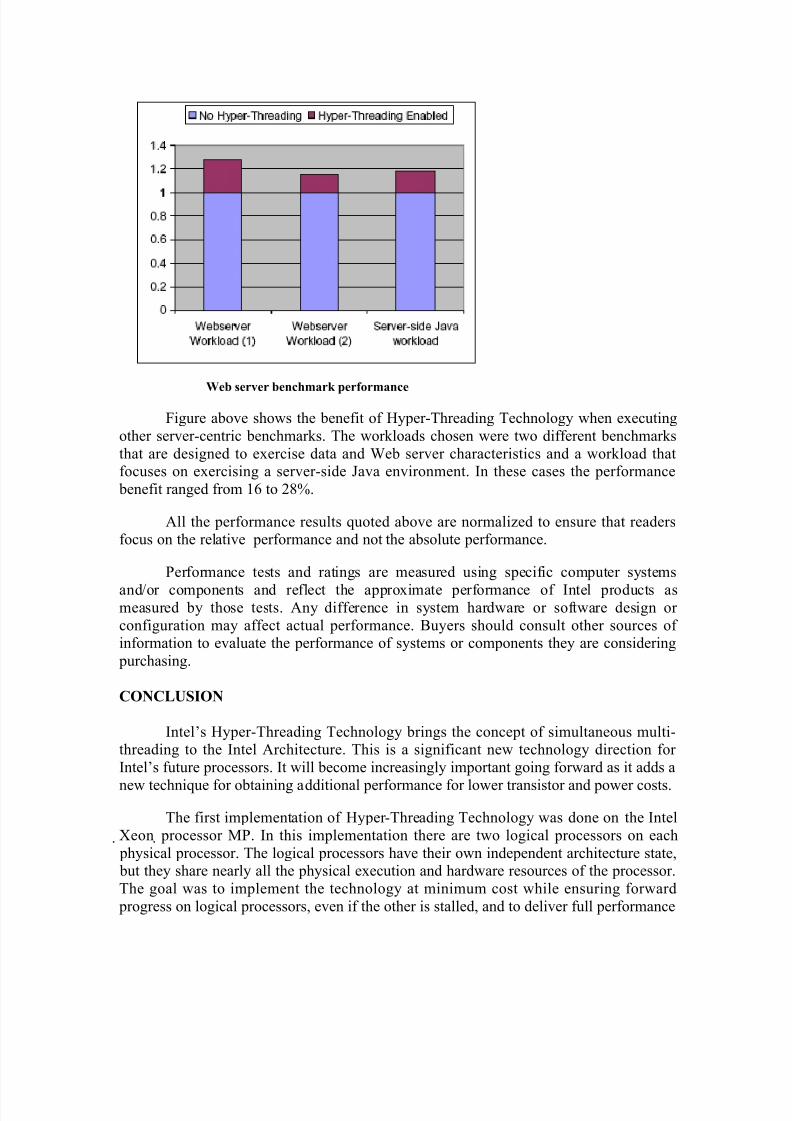
Figure above shows the benefit of Hyper-Threading Technology when executing
other server-centric benchmarks. The workloads chosen were two different benchmarks
that are designed to exercise data and Web server characteristics and a workload thatfocuses on exercising a server-side Java environment. In these cases the performance
benefit ranged from 16 to 28%.
All the performance results quoted above are normalized to ensure that readersfocus on the relative performance and not the absolute performance.
Performance tests and ratings are measured using specific computer systems
and/or components and reflect the approximate performance of Intel products asmeasured by those tests. Any difference in system hardware or software design or
configuration may affect actual performance. Buyers should consult other sources of information to evaluate the performance of systems or components they are considering
purchasing.
CONCLUSION
Intel’s Hyper-Threading Technology brings the concept of simultaneous multi-threading to the Intel Architecture. This is a significant new technology direction for
Intel’s future processors. It will become increasingly important going forward as it adds a
new technique for obtaining additional performance for lower transistor and power costs.
The first implementation of Hyper-Threading Technology was done on the Intel
Xeon processor MP. In this implementation there are two logical processors on each
physical processor. The logical processors have their own independent architecture state, but they share nearly all the physical execution and hardware resources of the processor.
The goal was to implement the technology at minimum cost while ensuring forward
progress on logical processors, even if the other is stalled, and to deliver full performance