HAL Id: hal-01974109 https://hal.archives-ouvertes.fr/hal-01974109 Submitted on 9 Jan 2019 HAL is a multi-disciplinary open access archive for the deposit and dissemination of sci- entific research documents, whether they are pub- lished or not. The documents may come from teaching and research institutions in France or abroad, or from public or private research centers. L’archive ouverte pluridisciplinaire HAL, est destinée au dépôt et à la diffusion de documents scientifiques de niveau recherche, publiés ou non, émanant des établissements d’enseignement et de recherche français ou étrangers, des laboratoires publics ou privés. Hyperelasticity Modeling for Incompressible Passive Biological Tissues Grégory Chagnon, Jacques Ohayon, Jean-Louis Martiel, Denis Favier To cite this version: Grégory Chagnon, Jacques Ohayon, Jean-Louis Martiel, Denis Favier. Hyperelasticity Modeling for Incompressible Passive Biological Tissues. Biomechanics of Living Organs, Elsevier, pp.3-30, 2017, 10.1016/B978-0-12-804009-6.00001-8. hal-01974109
Transcript
HAL Id: hal-01974109https://hal.archives-ouvertes.fr/hal-01974109
Submitted on 9 Jan 2019
HAL is a multi-disciplinary open accessarchive for the deposit and dissemination of sci-entific research documents, whether they are pub-lished or not. The documents may come fromteaching and research institutions in France orabroad, or from public or private research centers.
L’archive ouverte pluridisciplinaire HAL, estdestinée au dépôt et à la diffusion de documentsscientifiques de niveau recherche, publiés ou non,émanant des établissements d’enseignement et derecherche français ou étrangers, des laboratoirespublics ou privés.
Hyperelasticity Modeling for Incompressible PassiveBiological Tissues
Grégory Chagnon, Jacques Ohayon, Jean-Louis Martiel, Denis Favier
To cite this version:Grégory Chagnon, Jacques Ohayon, Jean-Louis Martiel, Denis Favier. Hyperelasticity Modeling forIncompressible Passive Biological Tissues. Biomechanics of Living Organs, Elsevier, pp.3-30, 2017,�10.1016/B978-0-12-804009-6.00001-8�. �hal-01974109�
Hyperelasticity Modeling for Incompressible Passive Biological Tissues
G. Chagnon, J. Ohayon, J. L. Martiel, D. Favier
Universite Grenoble-Alpes, TIMC-IMAG, F-38000 Grenoble, France.
CNRS, TIMC-IMAG, F-38000Grenoble, France
Abstract
Soft tissues are mainly composed of organised biological media giving them an anisotropic me-chanical behavior. Soft tissues also have the ability to undergo large elastic reversible deformations.Many constitutive models were developed to describe these phenomena. In this chapter, we dis-cuss several varying models and their constitutive equations which are defined by means of straincomponents or strain invariants. The notion of tangent moduli will be plotted for two well-knownconstitutive equations, and, we will illustrate how to implement explicitly a structural kinematicsconstraint in a constitutive law to derive the resulting Cauchy stress tensor.
Keywords: Hyperelasticity, Anisotropy, Kinematics constraint, Lagrange multiplier,Strain-Energy density functions
1. Introduction
In the last decades there has been a significant growth in interest to characterize the pas-sive anisotropic mechanical properties of soft incompressible biological tissues based on nonlinearcontinuum theory. Such constitutive approach is suitable to describe a wide variety of physicalmaterial behaviors in which the strain may be large [1, 2, 3, 4, 5]
Biological tissues are heterogeneous composite materials made of different media as epithelial,connective, muscular, neuronal... [6]. In these composite materials, the distributions of the internalconstituents are assumed to be locally uniform on the continuum scale. These tissues are oftenregarded as oriented cells surrounded by an extra cellular matrix, the whole behaving as anisotropiccontinuum media reinforced by different families of fibres of distinct orientations. The proportionof matrix and fibres, as their orientations, depend on the type of soft tissues (artery, skin, cornea,muscle ). All these materials present a complex mechanical behavior [7, 8],and can often supportlarge reversible deformations and strains. They can also present some other physical phenomenaas viscoelasticity [9, 10], stress softening [11, 12], strain hardening [13].
It is the aim of constitutive theories to develop mathematical models reproducing the realbehavior of biological tissues. Based on the nonlinear continuum mechanics theory, the anisotropicconstitutive law of the soft tissue can be derived from a strain-energy density function (SEDF)W, which is defined per unit of reference volume. Such SEDF is expressed as a function of thedeformation gradient (F) or the Green-Lagrange strain tensors (E)) (i.e. W “ W pFqq “ W pEqq).
Preprint submitted to Elsevier Book January 22, 2017
Two main formulations are used in the literature to express a SEDF. The first is based on the useof the Green-Lagrange strain tensor components, while in the second is expressed in term of straininvariants. For these two approaches, many constitutive models have been proposed in literature[14]. And although a thorough review and classification of all models is beyond the scope of thischapter, we will present and highlight some specific and pioneer models.
In this chapter, we will first introduce the notion of hyperelasticity. We will then present severalwell-known pioneer constitutive models using the two SEDF formulations. Additionally, we willexemplify how a constitutive stress-strain law can account for a kinematics constraint. And finally,by using two well-known SEDFs we will discuss the changes of the tangent elasticity moduli duringuniaxial extension tests. The relationships between the parameter of these two SEDFs and thelinear elasticity constant in small deformations will also be provided. Such relationships could beused to improve the identification method that needs to be conducted to quantify the materialconstants.
2. Mechanical formulation
2.1. Description of the deformation
The deformation of soft tissues is often described by means of the right and left Cauchy-Green tensors defined as: C “ FTF and B “ FFT , where F is the deformation gradient. Theprinciple components of the right or left Cauchy-Green tensors are λ2
i with i “ 1..3; λi are calledthe stretches. The logarithmic strains are simply expressed as εi “ lnpλiq in the principal basis.The Green-Lagrange strain tensor is directly defined in function of the right strain tensor byE “ pC ´ Iq{2, where I is the identity tensor, and its components are noted Eij with i, j “ 1...3.As the strain tensor components values depend on the basis in which they are written, some usethe stain invariants to express them. These invariant are defined for isotropic media as:
I1 “ trpCq, I2 “1
2
“
trpCq2 ´ trpC2q‰
, and I3 “ detpCq (1)
where ”tr” is the trace operator, and ”det” the determinant operator. It is to note that forincompressible materials I3 “ 1.
To describe the mechanical properties of a reinforced fibrous material, it is necessary to definefibre orientations. The fibres families are numbered i from 1 to q. An unit vector Npiq is introducedto describe the initial orientation of the ith fibre. An initial orientation tensor is defined as Apiq “
NpiqbNpiq. During deformation process, each material direction is transformed into npiq “ FNpiq,it represents the orientation of the fibre in the current state but npiq is not a unit vector.
The introduction of such directions leads to the definition of additional invariants relied to eachdirection. The invariant formulation of anisotropic constitutive equations is based on the conceptof structural tensors [15, 16, 17]. The invariants I4 and I5 can be defined for one direction i as:
Ipiq4 “ trpCApiqq “ Npiq ¨CNpiq, and I
piq5 “ trpC2Apiqq “ Npiq ¨C2Npiq. (2)
In the literature, in the case of two fibre directions p1q and p2q, a notation I4 and I6 is often used
for soft tissues [18] instead of Ip1q4 and I
p2q4 (or I5 and I7 instead of I
p1q5 and I
p2q5 ).
These invariants depend only on one direction but it is possible to take into account the inter-action between the different directions, by introducing a coupling between directions piq and pjqby means of two other invariants:
Ipi,jq8 “ pNpiq ¨NpjqqpNpiq ¨CNpjqq, and I
pi,jq9 “ pNpiq ¨Npjqq2. (3)
2
Ipi,jq9 does not depend on C and therefore does not affects the stress tensor components. Its values
corresponds to the value of Ipi,jq8 for C “ I, i.e. for no deformation. It is to note that other invariants
were also proposed in the literature [19, 20, 21] even if they are few used for the description of softtissue mechanical behaviour.
2.2. Strain-stress relationships
Living tissues are often considered as incompressible, thus the equations are written in a pureincompressible framework, i.e. I3 “ 1. The second Piola-Kirchhoff stress tensor can be directlycalculated by derivation of the strain energy function written in function of the whole invariants:
W pI1, I2, Ipiq4 , I
piq5 , I
pi,jq8 , I
pi,jq9 q, with i, j “ 1..q:
S “ 2
«
pW,1 ` I1W,2qI´W,2C`
qÿ
i
Wpiq,4 Npiq bNpiq `
qÿ
i
Wpiq,5
´
Npiq bCNpiq `NpiqCbNpiq¯
`ÿ
i‰j
Wpi,jq,8 pNpiq ¨NpjqqpNpiq bNpjq `Npjq bNpiqq
ff
` pC´1 (4)
where W,k “BWBIk
, and p is the hydrostatic pressure. The Eulerian stresses, i.e., the Cauchy stressesare directly obtained by the Push-forward operation [3]. To ensure that the stress is identicallyzero in the non-deformed configuration, it is required that for each fibre orientation:
@i Wpiq,4 ` 2W
piq,5 “ 0, (5)
for zero deformation [22].The use of these equations in a finite element codes imposes to use a quasi-incompressible
framework with a decomposition into volumetric and isochoric parts of the energy density. Detailsabout the elasticity tensors are given in [23, 24, 25, 26]. A particular attention should be focusedon the choice of the volumetric function in order to avoid any non-physical response [27, 28, 29].
2.3. Stability
The strain energy density cannot be chosen without restriction, the strong ellipticity conditionmust be verified. For three-dimensional problems [30], the strong ellipticity was characterised forcompressible isotropic materials [31], and for incompressible ones [32]. The generic condition toverify for the strain energy in the absence of body forces [33, 34, 35] can be written as:
1
JFprFqs
B2W
BFirFjsnpnqmimj ą 0 with m ‰ 0 and n ‰ 0, (6)
where m and n are arbitrary two non-zero vectors. Nevertheless, this condition is always difficultto verify. Thus, some proposed another way to tackle the strong ellipticity condition. It is knownthat polyconvexity implies ellipticity [36, 37, 38]. As a consequence, the polyconvexity in the senseof Ball [39, 40] is used, even if it is more restrictive than strong ellipticity.
3
3. Constitutive equations for soft biological tissues
Even if soft tissues are made of cells and fibres, when the quantity of fibres is weak or when theirmechanical influence can be neglected, an isotropic modelling can be efficient. Most of isotropicconstitutive equations were not developed for soft tissues but for rubber like materials and usedfor soft tissues, they are listed in [41, 42]. Nevertheless, soft tissues often present a larger strainhardening than rubber like materials. This implies to the development of specific constitutiveequations, the clue for the constitutive equations is to present an important change of slope in thestrain-stress curve for moderate deformations. This leads to the development of many constitutiveequations with exponential form. In an isotropic point of view, Demiray et al [43] proposed:
W “c1
c2
!
exp”c2
2pI1 ´ 3q2
ı
´ 1)
(7)
where c1, c2 are material parameters. Similar exponential forms can be proposed for the secondinvariant [44] but this invariant is very rarely used for soft tissues. Nevertheless, the use of isotropicapproach is very limited, anisotropic modelling are necessary to capture the real behaviour of manysoft tissues.
3.1. Introduction to anisotropy
The anisotropy of the tissues depends on the characteristics of its components i.e. fibres,matrix and the interaction between them. It exists some modelling that tend to describe thesoft tissues from a statistical point of view. It relies on the study of the collagen network andit uses an upscaling method [45, 46]. A collagen molecule is defined by its length, its stiffnessand its helical structure. Some studies come from approaches developed for rubber like material[47, 48, 49]. Unlike polymer chains in rubber which are uncorrelated nature, collagen chains inbiological tissues have to be classified as correlated chains for a statistical point of view. It thisway, different theories are considered to represent the chains, as for example wormlike chains witha slight varying curvature [50], or sinusoidal, zig-zag or circular helix representations [51, 52, 53].This leads to the development of constitutive equations that need numerical tool for integration inspace. A good use of these models necessitates specific experimental measures of the physiologicalproperties of the soft tissues.
In this chapter, it is decided to focus more on phenomenological equations that are directlyexpressed by means of strain components or strain invariants. But the choice of the number of fibredirections depends on the morphology of the tissue. The easiest formulation is with one directionto represent transverse isotropic behaviour but in other cases, more directions are needed. Forexample, in the first modelling of arteries mechanical behaviour, two fibre directions were used[54], before being extended to four directions [55, 56] and to n directions [57] and used for examplewith eight directions for cerebral aneurysms [58]. The reinforced directions can also be used asequivalent mechanical behaviour without any physical meaning, this means that model directionsdo not correspond to real fibre directions. Even if it is possible to describe the mechanical behaviourwith this representation, the physical meaning is lost.
3.2. Green-Lagrange tensor components to describe anisotropy
An easy way to create an anisotropic constitutive equation is to write it as a sum of thecontribution of the components of the strain tensor. Finally a weight is chosen for each component.As previously explained, soft tissues present an important strain hardening so an exponential form
Table 1: Some infinite I4, I5 series developments proposed to model transverse isotropic soft tissues where ak, bk,ck, dk, ckm and cklmn are material parameters (It is to note that c0010=0, c0001=0 for [78, 79]).
is often chosen. Fung and co-authors conducted several studies [59, 60, 61] using the followingglobal form of SEDF W “ c
2pexpQ ´ 1q. Q is here a function of the strain components that canbe written as Q “ AijklEijEkl where Aijkl are material parameters. Different formulations werewritten in two and three dimensions. A review about the different equations can be found in [62].These constitutive equations were often used for cardiovascular soft tissues (i.e. heart, arteries...)and are often written in cylindrical coordinates. Different constitutive equations have proved theirefficiency for different biomedical applications. In this chapter, the example of Guccione et al [63]is selected. The constitutive equation for one fibre reinforcement is written as:
Q “ bfE211 ` btpE
222 ` E
233 ` E
223 ` E
232q ` bfspE
212 ` E
221 ` E
213 ` E
231q (8)
where bf , bt and bfs are material parameters. It is to note that the exponential form is not theonly that is used even if it is largely spread. Some other forms as polynomial [64, 65, 66] or inversefunction [67] have also been proposed. For all these models, the main difficulty is that the materialparameters have no physical meaning and their fit needs to be perform carefully [68, 69, 54].
3.3. Strain invariants formulation
3.3.1. Classical formulation
The idea is here to express the constitutive equation by means of all the invariants whichare more numerous in an anisotropic context. A good way to describe any function is to use aseries development. It represents a generalisation to anisotropy of Rivlin series [70]. Nevertheless,it is to note that different authors proposed to write the series developments in different ways.Some expressions are detailed in table 1. The term k “ 2 of Kaliske model [71] corresponds tothe standard reinforcing model [72, 73, 74, 75], not initially proposed for soft tissues but whichrepresents the most simple function in I4 that can be used. It is to note that the use of
?I4 permits
to obtain a model that represents the behaviour of a linear spring with the quadratic formulation[76, 77]. As for isotropy, the series cannot be used in a infinite version and a main point to discussis the choice of the terms that must be kept. Some discussions about particular cases are reportedin [72, 82, 22, 80]. Let us mention that few SEDFs involving the I5 invariant have been proposed.In most of the cases, expressions limited to I4 are preferred. But the use of only I4 or I5, insteadof the both invariants is a still questionable as it leads to the same shear modulus in direction andorthogonal to the reinforced direction [22]. Moreover today, no series development using I8 wasproposed.
5
The description of a behavior with strong strain hardening using polynomial SEDFs needs toomany terms. To avoid this, other forms based on exponential functions were proposed. It consistsin increasing largely the strain energy for the material when stretched in fibre direction. A firstexponential constitutive equation was proposed by Humphrey and Yin [83]:
W “ c1pexppc2pa
I4 ´ 1q2q ´ 1q (9)
This expression was later expressed by means of I4 instead of?I4 by Holzapfel et al [54]:
W “ µpI1 ´ 3q `c1
2c2
“
exppc2pI4 ´ 1q2q ´ 1‰
(10)
This model was widely used for different soft tissues. Later, it has been extended to take intoaccount the isotropic and anisotropic parts ratio by introducing a weighting factor between thecontributions of I1 and I4 [84]. This factor κ represents a measure of dispersion in the fibreorientation (it is noted HGO model in the rest of the paper):
W “ µpI1 ´ 3q `c1
2c2
exp`
c2
`
p1´ κqpI1 ´ 3q2 ` κpI4 ´ 1q2˘
´ 1˘(
(11)
In the three previous SEDFs (9,10,11), µ, c1, c2 and κ are material parameters. The form of theterm/s in the exponential function has/have largely evolved and many other expressions have beenproposed. The reader can refer to [85, 86, 87, 88, 89, 90, 91] for example. Recently, a general formfor the SEDF was proposed by Pena et al [92]:
W “γ
aηrexppηpI1 ´ 3qaq ´ f1pI1, aqs `
cibdirexppdipI
piq4 ´ I0
4 qbq ´ gpI
piq4 , I0
4 , bqs. (12)
The choice of the functions f1 and g permits to generalise many different models. γ, η, a, b, ci,di and I0
4 are material parameters, I04 represents the threshold to reach for the fibre to become
loaded. To our knowledge, only few SEDF involving also I5 was proposed for soft tissue [93]:
W “ apI1 ´ 3q ` bpI2 ´ 3q `c1
2c2
`
exp
c2pI4 ´ 1q2(
´ 1˘
`c3
2c4
`
exp
c4pI5 ´ 1q2(
´ 1˘
(13)
where a, b, c1, c2, c3 and c4 are material parameters. Even if this constitutive equation was initiallydeveloped for arteries [94, 95, 96], it was also used for different biological tissues, as for examplehuman cornea [97], erythrocytes [98], the mitral valve [99], trachea [100, 101], cornea [102, 103],collagen [104], abdominal muscle [105].
Nevertheless, the constitutive equations for soft tissues could be written using other mathe-matical functions instead the exponential one. As for rubber like materials, several mathematicalfunctions have been proposed. Using an exponential function supposes a strong strain hardeningeffect. To overcome such limitation several different constitutive equations can also be used for softtissues as they present similar abilities. Some equations are detailed in table 2. It is to note thatthese equations developed for composite materials are also written with I5. The first equationswere proposed for soft tissues and use ln or tanh functions. The second part of the table listsa series of SEDFs that were proposed to describe the mechanical behaviour for fibres reinforcedmaterials but not soft tissues. But as explained previously, many soft tissues are fibres reinforcedmaterials as a consequence all these SEDFs could also be used for soft tissues and can bring newabilities for teh modelling.
6
Non classical constitutive equations with square root, tanh and ln functions.
Dorfmann et al. [106] W “ c2
”
1´ c3 tanh´
I4´1c4
¯ı
“
exppc5pI4 ´ 1q2q ´ 1‰
Limbert and Middleton [107] W “ 2c5
?I4 ` c6 lnpI4q
Calvo et al. [108] W “ 2c5
?I4 ` c6 lnpI4q ` c7
Constitutive equation initially developped for reinforced materials
Horgan and Saccomandi [79] W,4 “ ´c1`c2pI4´1q
c3`c4pI4´1q`c5pI4´1q2`c6pI5´2I4`1q
Horgan and Saccomandi [79] W,4 “ ´c1`c2pI4´1qc3`c4pI4´1q
Horgan and Saccomandi [79] W “ ´c2c3
´
I4 ´ 1` c3 ln´
1´ I4´1c3
¯¯
Horgan and Saccomandi [79] W “ ´ c2n c3 ln
´
1´ pI4´1qn
c3
¯
Horgan and Saccomandi [79] W “ ´c1c2 log´
1´ pI5´1q2
c2
¯
Ruter and Stein [78] W “ c2 pcoshpI4 ´ 1q ´ 1q
Ogden and Saccomandi [109] W “ ´ c22 c3 ln
´
1´ pI4´1q2
c3
¯
Markert et al. [110] W “ c1c2pIc2{24 ´ 1q ´ c1 lnpI
1{24 q
Demirkoparan et al [111, 112] W “ 23
´
I4c21` 2 c1?
I4´ 3
¯
Lurding et al. [113] W “ c1pI1 ´ 3q ` c2pI1 ´ 3qpI4 ´ 1q ` c3pI24 ´ I5q
`c4p?I4 ´ 1q2 ` c5 lnpI4q
Chui et al. [113] W “ c1 lnp1´T q`c5pI1´3q2`c6pI4´1q2`c7pI1´3qpI4´1q
with T “ c2pI1 ´ 3q2 ` c3pI4 ´ 1q2 ` c4pI1 ´ 3qpI4 ´ 1q
Table 2: Some original forms of constitutive equations using I4 and I5, where ci with i “ 1...7 are material parameters.
7
3.3.2. Coupling influence
The detailed SEDFs of the previous paragraphs do not take into account the coupling thatcan exist between the different fibre families. The additive decomposition that is used impliesa superposition principle. A first way to create a coupling is to propose constitutive equationspresenting multiplicative terms between the different directions. In this spirit, an anisotropicSEDF W with two fibre families was proposed for pneumatic membranes [114]:
W “ cp1q1
´
Ip1q4 ´ 1
¯β1` c
p1q2
´
Ip1q5 ´ 1
¯β2` c
p2q1
´
Ip2q4 ´ 1
¯γ1` c
p2q2
´
Ip2q5 ´ 1
¯γ2
`cp1qc pI1 ´ 3qδ1´
Ip1q4 ´ 1
¯δ1` cp2qc pI1 ´ 3qδ2
´
Ip2q4 ´ 1
¯δ2` cp1,2qc
´
Ip1q4 ´ 1
¯η ´
Ip2q4 ´ 1
¯η. (14)
This strain energy allows coupling between the different directions, but the additive decomposition
of the constitutive equation permits to fit separately the different parameters cpjqi , δi and βi. The
coupling between the two directions is given by the parameter cp1,2qc . This series development can
be imagined with any terms and any powers to change the coupling. More recently and in the samespirit, Holzapfel and Ogden [115] develop an interesting structurally based orthotropic model ofthe passive myocardium that accounts for muscle fibre direction and the myocyte sheet structure.
Another method consists in coupling invariants from different directions [37], a new quantityis created taking into account the contribution of the different directions, the following invariantexpression was proposed:
α2Ip1q24 ` 2λp1´ αqI
p1q4 I
p2q4 ` p1´ αq2I
p2q24 with α P r0, 1s. (15)
α represents a material parameter. This expression permits to measure the deformation in two di-rections with only one invariant. Nevertheless, this has not yet been used in constitutive equations.A simple additive decomposition of the invariants in a same function can create the coupling [116]and can be used [117] as in the exponential form:
W “c1
c2
”
exp´
c2
´
Ip1q4 ` I
p2q4 ´ 2
¯¯
´ c2
´
Ip1q4 ` I
p2q4
¯
` 2c2 ´ 1ı
. (16)
A generalised weighted expression of the constitutive equation was also developed [118, 119]:
W “1
4
ÿ
r
µr
«
1
αr
˜
exp
˜
αr
˜
ÿ
i
γiIpiq4 ´ 1
¸¸
´ 1
¸
`1
βr
˜
exp
˜
βr
˜
ÿ
i
γiPpiq5 ´ 1
¸¸
´ 1
¸ff
.
(17)
with P5 “ trpCofpCqApiqq where Cof is the cofactor operator, µr, βr, γi and αr are materialparameters.
These models are coupling the stretches of the different fibres but do not take into accountthe shear in the matrix due to the presence of fibres. To handle such limitation we need to
account for Ipi,jq8 and I
pi,jq9 . The idea is thus to add terms in the strain energy taking into account
these invariants. Few constitutive equations were proposed in the literature, but one example wasproposed for oesophageal tissues where a quadratic function was added [120]:
W “ c1c3
exprc3pI1 ´ 3qs ` c2c5
exprc5pI2 ´ 3qs
` c4c27
!
exprc7pIp1q4 ´ 1qs ´ c7pI
p1q4 ´ 1q ´ 1
)
` c6c28
!
exprc8pIp2q4 ´ 1qs ´ c8pI
p2q4 ´ 1q ´ 1
)
` c9
”
Ip1,2q8 ´ I
p1,2q9
ı2,
(18)
8
where ci with i “ 1...9 are material parameters. For annulus fibrous tissues, the influence of the
interaction between the layers was modelled [121] with a term taking into account Ip1q4 , I
p2q4 and
Ip1,2q8 :
W “c1
2c2
¨
˚
˝
exp
¨
˚
˝
c2
¨
˚
˝
Ip1,2q8
´
Ip1q4 I
p2q4 I
p1,2q9
¯1{2´
b
Ip1,2q9
˛
‹
‚
2˛
‹
‚
´ 1
˛
‹
‚
. (19)
A similar form from exponential model was proposed also for I8 [122]:
W “c1
c2
»
—
–
exp
¨
˚
˝
c2
´
Ip1,2q8
¯2
Ip1,2q9
˛
‹
‚
´ 1
fi
ffi
fl
. (20)
In the two previous models c1 and c2 are material parameters. Few invariant-coupling models wereused for biological tissues, but they are proposed for composite material [123, 124]. In comparisonwith other models, these approaches take into account the shear strain in the material whereas thefirst models couple the deformations of the different fibres.
In a classical approach, as in plasticity or viscoelasticity, one proposes to decompose the strainenergy into three parts W “Wm `W f `W fm [125], where the three terms are the strain energyof the matrix, of the fibres and of the interactions between fibres and matrix, respectively. Thedecomposition of the strain energy function into different parts permits to analyse the loading statesand to propose constitutive equations reproducing the strain endured by the fibre, the matrix andthe interface. This leads to the construction of different function families [126]:
$
’
’
&
’
’
%
Wm “ 12c1fpI4qpI1 ´ 3q,
W f “ c1g1pI4q
´
I5´I24I4
¯
,
W fm “ c1g2pI4q
´
I1 ´I5`2
?I4
I4
¯
.
(21)
Another basic form was also proposed for the interaction between the fibres and the matrix [125]:
W fm “ g2pI4q
„
I4
I3pI5 ´ I1I4 ` I2q ´ 1
2
, (22)
where f , g1 and g2 are functions to define and c1 is a material parameter. The first functioncorresponds a generalisation of the neo-Hookean model [127]. Few functions for f , g1 and g2
have been proposed for the moment, the first propositions are based on exponential functions[126, 128, 129].
4. About some specific constitutive equations
In this section, two well known constitutive equations, one expressed in term of strain compo-nents [63] and the other in term of strain invariants [84] are detailed on classical uniaxial mechanicaltests.
9
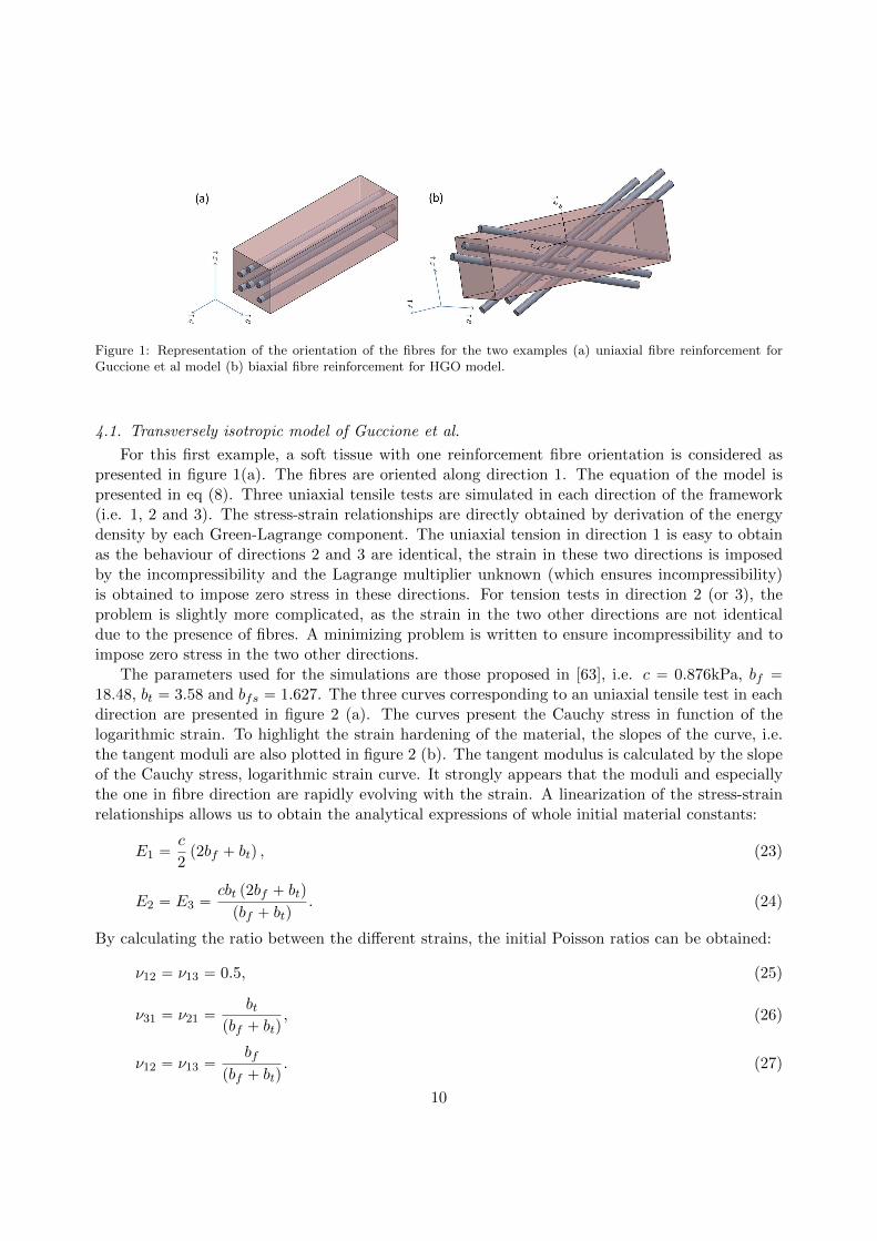
Figure 1: Representation of the orientation of the fibres for the two examples (a) uniaxial fibre reinforcement forGuccione et al model (b) biaxial fibre reinforcement for HGO model.
4.1. Transversely isotropic model of Guccione et al.
For this first example, a soft tissue with one reinforcement fibre orientation is considered aspresented in figure 1(a). The fibres are oriented along direction 1. The equation of the model ispresented in eq (8). Three uniaxial tensile tests are simulated in each direction of the framework(i.e. 1, 2 and 3). The stress-strain relationships are directly obtained by derivation of the energydensity by each Green-Lagrange component. The uniaxial tension in direction 1 is easy to obtainas the behaviour of directions 2 and 3 are identical, the strain in these two directions is imposedby the incompressibility and the Lagrange multiplier unknown (which ensures incompressibility)is obtained to impose zero stress in these directions. For tension tests in direction 2 (or 3), theproblem is slightly more complicated, as the strain in the two other directions are not identicaldue to the presence of fibres. A minimizing problem is written to ensure incompressibility and toimpose zero stress in the two other directions.
The parameters used for the simulations are those proposed in [63], i.e. c “ 0.876kPa, bf “18.48, bt “ 3.58 and bfs “ 1.627. The three curves corresponding to an uniaxial tensile test in eachdirection are presented in figure 2 (a). The curves present the Cauchy stress in function of thelogarithmic strain. To highlight the strain hardening of the material, the slopes of the curve, i.e.the tangent moduli are also plotted in figure 2 (b). The tangent modulus is calculated by the slopeof the Cauchy stress, logarithmic strain curve. It strongly appears that the moduli and especiallythe one in fibre direction are rapidly evolving with the strain. A linearization of the stress-strainrelationships allows us to obtain the analytical expressions of whole initial material constants:
E1 “c
2p2bf ` btq , (23)
E2 “ E3 “cbt p2bf ` btq
pbf ` btq. (24)
By calculating the ratio between the different strains, the initial Poisson ratios can be obtained:
ν12 “ ν13 “ 0.5, (25)
ν31 “ ν21 “bt
pbf ` btq, (26)
ν12 “ ν13 “bf
pbf ` btq. (27)
10
ε
σ
0 0.05 0.1 0.15 0.2 0.250
10
20
30
40
50
σ33
σ11
σ22
(a)
(kP
a)
εM
od
uli
(kP
a)
0 0.05 0.1 0.15 0.2 0.250
20
40
60
80
100
E3
E
E
1
2
(b)
Figure 2: Guccione et al model (a) representation of the strain-stress curves for three different tensile tests, (b)representation of the tangent moduli for the same tests (ε is the Green-Lagrange strain and σ the Cauchy stress).
By simulating shear tests, the initial shear moduli can also be obtained:
µ12 “ µ13 “cbf2
(28)
µ23 “cbt2
(29)
It is important to notice that these initial material parameters are no longer constant values inlarge strains and thsee relationships (cf. Eq 23-29) are only valid for strain amplitudes lower thanapproximately 2%. However, one can take advantage of such relationships, to improve the perfor-mance of the identification method that needs to be conducted to obtain the material parametersfrom experimental data. Two steps are necessary to obtain the material constants. In a firststep, one can use these linear relationships to quantify some material constants based on the smallstrain experimental responses. In the second step, the previous determined set of initial mate-rial constants can be used to partially initiate the optimization process conducted on the entireexperimental responses including in the large strain domains.
4.2. HGO orthotropic model
In this section, a material presenting two reinforced directions is used. A representation ofthe material is presented in figure 1(b). The two fibre families are in the plane (1-3), they aresymmetric with respect to the plane (2-3) and present an angle φ relative to axe 1. The equationof the HGO model was presented previously (eq 11). The parameters identified for media arteryare used, µ “ 1.27kPa, k1 “ 21.6kPa, k2 “ 8.21, φ “ 20.61, ρ “ 0.25 [84]. Different hypothesesexist in the literature about the contribution of the fibres in compression; some consider thatthey act whereas some consider that they do not contribute to the stress. In this example, it isconsidered that the fibres can be compressed and have the same parameters as in tension. The
11
same simulations as in the previous section are performed, i.e. three uniaxial tensile tests in thethree axis 1, 2 and 3. Due to the orientation of the fibres, a minimizing scheme is necessary foreach test (the transverse strains should verify the incompressibility hypothesis and the stress nullin the transverse directions). A simulation of the three tensile tests is presented in figure 3 (a).Moreover, the tangent moduli are also presented in figure 3 (b). The conclusions are similar to the
ε
σ
0 0.05 0.1 0.15 0.2 0.250
10
20
30
40
(kP
a)
σ
σ
σ33
11
22
(a) ε
Mo
du
li(k
Pa)
0 0.05 0.1 0.15 0.2 0.250
100
200
300
400
500
600
700
800
E
E
E3
1
2
(b)
Figure 3: HGO model (a) representation of the strain-stress curves for three different tensile tests, (b) representationof the tangent moduli for the same tests (ε is the Green-Lagrange strain and σ the Cauchy stress).
previous model with tangent moduli that are increasing exponentially with strain. As previously,the linearization permits to determine the initial moduli and Poisson ratio, and the following valuescan be obtained:
E1 “ 2µ3µ` 4k1ρ
`
sin4 φ` cos4 φ´ sin2 φ cos2 φ˘
µ` k1ρ`
sin2 φ´ cos2 φ˘2 , (30)
E2 “ 2µ3µ` 4k1ρ
`
sin4 φ` cos4 φ´ sin2 φ cos2 φ˘
µ` k1ρ sin4 φ, (31)
E3 “ 2µ3µ` 4k1ρ
`
sin4 φ` cos4 φ´ sin2 φ cos2 φ˘
µ` k1ρ cos4 φ, (32)
ν12 “µ´ 2k1ρ sin2 φ
`
cos2 φ´ sin2 φ˘
2´
µ` k1ρ`
sin2 φ´ cos2 φ˘2¯ , (33)
ν23 “µ` 2k1ρ sin2 φ cos2 φ
2`
µ` k1ρ sin4 φ˘ , (34)
ν32 “µ` 2k1ρ sin2 φ cos2 φ
2 pµ` k1ρ cos4 φq. (35)
In the same way as tangent moduli, the Poisson ratios are evolving with the strain and areaffected by the energy to compress the fibres. As previously pointed out at the end of the section4.1, the performance of the identification method that needs to be conducted to obtain the materialparameters from experimental data could be improved by taking advantage of such relationships.
12
4.3. About the two models
These two constitutive equations, even if they are not written in the same formalism, presentvery similar tendencies. It is to note that these models are elaborated to present an importantstrain hardening leading to a large increase of the tangent moduli when the material is stretched.Even if links with the initial moduli exists, these links should be used very carefully. They cannotbe used to fit the model, these values are not constant for the models. They represent a linearizationat the starting point. Moreover, it is often very difficult to obtain the experimental data near zerodeformation due to experimental errors and due to the difficulty to identify the zero configuration ofthe samples. Nevertheless, the values of these linearized parameters highlight that the parametersof the models act on every components of the elasticity tensor and thus on the tangent elastictensor.
A key point in the modelling is to define when the fibres start to resist when stretched. Manyauthors considered that the fibres must reach a threshold before opposing a stress. In this way, athreshold parameter can be introduced in all the constitutive equations presented in this review. Itconsist in replacing pI4´1q by pI4´I
04 q, or p
?I4´1q by p
?I4´
a
I04 q into the constitutive equations.
I04 corresponds to the needed deformation to generate stress, see for example [84, 92, 108, 130]. This
new parameter permits to control easily the beginning of the strain hardening. Its value stronglydepends on the choice of the reference on the zero state of the experimental data. This zero stateis always difficult to identify and vary between post-mortem and in-vivo states and can dependon the person who performs the test. The addition of such parameter can strongly influence thefigures presented in this paragraph.
According to the hypothesis that is used with the fibres in compression (they generate or notstresses), some strong changes of slopes can also be observed when the fibres change of loading (ten-sion to compression or compression to tension). This phenomenon can appear even in monotonicloadings due to the rotation of the fibres during the deformation process.
5. How to account for a kinematics constraint in a constitutive law?
In this example, we illustrate how a kinematics constraint may be explicitly included in a passivestress-strain constitutive law. Extrapolations from cardiac muscle fibre arrangement to myocardialstress are realistic when we also account for the effects of the connective tissue. It is hypothesizedthat a part of that connective tissue, surrounding group of myocytes, affects the stress in theperpendicular direction of the muscle fibres running on the tangential plane of the ventricular wall.Based on the previous scanning electron microscope observations [131], we proposed a connectivetissue organization illustrated in Fig. 4. We assumed that the myocytes are roughly cylindricaland that two oriented groups of myocytes (idealized as two cardiac fibres) are surrounded byinextensible collagen networks. So, during the passive compression in the fibre direction of anincompressible myocardial sample, the myocyte diameters increase and because the surrounding”belts” of collagen are inextensible, the adjacent muscle cells become closer. Such kinematic relationbetween the muscle fibre and cross-fibre extension ratios (named λf0 and λfK0
, respectively) is givenby:
h´
λf0 , λfK0
¯
“ 1´ λfK0`a
Dpπ ´ 2q
´
1´ λ´1{2
fK0
¯
“ 0 (36)
with D “ 4a ` d where a is the initial myocyte radius and d is the initial distance between thetwo cells (Fig. 4). Notice that this kinematics constraint exists only if the cardiac fibre is under
13
Figure 4: Schematic illustrations of a myocardial sample and the kinematic constraint induced by the collagennetwork surrounding the muscle fibres. A) Before compression (reference state). B) After or during the uniaxialcompression in the fibre direction (deformed state). fi: fibre direction define by the unit vector f0 ; c´ fi: cross-fibredirection in the tangential plane define by the unit vector fK0 ); c´ fi˚: cross-fibre direction perpendicular to thetangential plane (adapted from [133]).
compression (i.e. if λf0 ă 1). In terms of strain invariants, this kinematics constraint becomes:
h´
I4f0 , I4fK0
¯
“ 1´ I1{2
4fK0`a
Dpπ ´ 2q
´
1´ I´1{4
4fK0
¯
“ 0 if I4f0 ă 1 (37)
with
I4f0 “ f0 ¨ pCf0q and I4fK0“ fK0 ¨
`
CfK0˘
(38)
where f0 and fK0 are two unit vectors given in the reference configuration. These vectors areparallel and perpendicular to the muscle fibres, respectively. Both vectors are running on thetangential plane of the ventricular wall. To satisfy this kinematic constraint the SEDF of thepassive incompressible tissue needs to be split into a material term Wmat pEq and a kinematicscontribution Wkin pEq :
W pEq “Wmat pEq `Wkin pEq (39)
with :
Wkin pEq “ ´1
2qh
´
I4f0 , I4fK0
¯
(40)
The scalar function q introduced in Eq. 40 serves as an additional indeterminate Lagrange multi-plier to insure the kinematics condition given by Eq. 37. As a result, the expression of the Cauchystress tensor σ, is given by (see Chapter 2 of this book):
σ “ FBWmat pEq
BEFT ` σkin ´ pI (41)
14
with
σkin “ FBWkin pEq
BEFT “ ´q
»
–
Bh´
I4f0 , I4fK0
¯
BI4f0
f b f `Bh
´
I4f0 , I4fK0
¯
BIK4f0fK b fK
fi
fl (42)
and
Bh´
I4f0 , I4fK0
¯
BI4f0
“a
4Dpπ ´ 2qI
´5{44f0
(43)
Bh´
I4f0 , I4fK0
¯
BIK4f0“ ´
1
2I´1{2
4fK0(44)
where f “ Ff0, fK “ FfK0 , p is a second Lagrange multiplier associated with the kinematicsincompressibility constraint detpFq “ 1, and I is the identity matrix. An extended active versionof this model has been proposed to explain the observed left ventricular wall thickening during theejection phase of the cardiac cycle [132, 133].
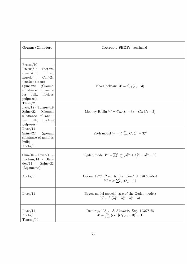
6. Passive hyperelastic SEDFs used in the book chapters
In this book, several strain energy density functions (SEDFs) were used to model biologicaltissues. For compressible and quasi-incompressible media the SEDF can be given in decoupledform as:
W pCq “Wiso
`
C˘
`Wvol pJq
where Wvol and Wiso are SEDFs describing the volumetric and isochoric response of the material,respectively, J is the volume ratio (J “ detF , where F is the deformation gradient), C “ F T ¨F isthe right Cauchy-Green strain tensor and C “ J´2{3C is the modified right Cauchy-Green straintensor. Once we know the form of the SEDF, the 2nd Piola-Kirchhoff stress tensor can be derived[134] as:
S “ Siso ` Svol,
with Svol “ 2BWvolBJ
BJBC and Siso “ 2BWiso
BC: BCBC . For purely incompressible material (J “ 1), the
2nd Piola-Kirchhoff stress tensor adopts the following form:
S “ 2BWiso
BC´ pC´1
where p is the Lagrange multiplier introduced to enforce incompressibility. In the Table 3 onelists the main passive hyperelastic SEDFs WisopCq, used in this book to model the biomechanicalbehavior of living organs, when assuming purely incompressible biological tissues. The SEDFs forquasi-incompressible biological tissues are, in general, given as function of the invariants referredto C (here denoted Ik, k “ 1, ..., 5 and k “ 8). However, in literature some SEDFs are given withthe help of the invariants referred to E (here denoted I˚k , k “ 1, ..., 5 and k “ 8). The relationshipbetween these two families of invariants is:
15
I˚1 “ Tr pEq “1
2pI1 ´ 3q
I˚2 “1
2
´
Tr pEq2 ´ Tr`
E2˘
¯
“1
4p´2I1 ` I2 ` 3q
I˚3 “ detE “1
8pI1 ´ I2 ` I3 ´ 1q
I˚4 “ E : f b f “1
2pI4 ´ 1q with f ¨ f “ 1
I˚5 “ E2 : f b f “1
4pI5 ´ 2I4 ` 1q
I˚8 “ E : f b s “1
2I8, with f ¨ s “ 0
16
Organs/Chapters Orthotropic SEDFs
Coronary /2, 9 Holzapfel et al., 2005,Am J Physiol, 289:H2048-2058
Aorta/8 W “ µ pI1 ´ 3q `ř2i“1
k12k2
!
exp”
k2
´
p1´ ρq pI1 ´ 3q2 ` ρ pI4i ´ 1q2¯ı
´ 1)
Skin/16 Holzapfel et al., 2001, J. Elasticity 61:1-48
W “µ2 pI1 ´ 3q ` µ
ř2i“1
ki12ki2
exp“
ki2ptrpHi ¨Cq ´ 1q2‰
´ 1(
with Hi “ κiI ` p1´ 3κiqe1 b e2
Esophagus/7 Fung et al.,1979. Am J of Physiology, 237:H620-H631
Skin/16 Gambarotta et al., 2005. J. Biomech. 38:2237-2247W “ a1I
˚21 ` a2I
˚2 ` a3 exp
“
a4I˚21 ` a5I
˚2
‰
Table 3: Non exhaustive list of passive hyperelastic SEDFs presented in this book to model thebiomechanics of living organs. Ii pCq , i “ 1, 2, 3 are the invariants of the right Cauchy-Green tensor; I4i “C : pfi b fiq is the 4th invariant given by the contraction of C and the structural tensor fi b fi where fi isthe direction of the ith family of fibers in the reference configuration; similarly, we define the 5th invariant asI5i “ C2 : pfi b fiq; finaly, we also define I8ij “ C : pfi b fjq with i ‰ j. λi, i “ 1, 2, 3 are the principal stretches;Eij denote the components of the Green-Lagrange strain tensor E. Subscript used in the expression of the Eij refereither (i) to the cylindrical coordinate system pr, θ, zq, (ii) to the global coordinate frame p1, 2, 3q or (iii) to the locallyorthogonal frame pf, s, nq where f is the fiber direction and s is the direction orthogonal to f but in the fiber plane.I˚k , k “ 1, 2, 3 are the invariants of the Green-Lagrange tensor E. I˚4f and I˚5f are, respectively, E : pfi b fiq and
E2 : pfi b fiq .
21
7. Discussion
The number of constitutive equations is quite large, some interesting equations were listed inthis chapter. A more exhaustive review can be found in [14]. Moreover, it exists other modellingapproaches with a new class of elastic solids with implicit elasticity [135] that can also describe thestrain limiting characteristics of soft tissues [136]. These theories are also elastic as they do notdissipate energies even if they are written in terms of strain rate and stress rate.
The question of the choice of the constitutive equation is a key point as it has large consequenceson the simulations that can be performed. The links betwwen the initial material constants withthe hyperelastic SEDF parameters are presented in this chapter for two classical models, but it isimportant to keep in mind that these relationship can only be used to initiate the identificationoptimization process.
Even today, for some applications, isotropic constitutive equations are abusely used to describethe mechanical behaviour of different soft tissues. In most of the cases, this simplifed models aremisleading and inappropriate as most of soft tissues present a fibre structure that must be takeninto account.
The use of anisotropic strain energy necessitates introducing fibre directions to model themechanical properties of the soft tissue. Two ways of thinking exist, some consider that the fibreorientation should be physically motivated, i.e. that it represents the real orientation of fibres inthe material, whereas some consider that the orientation of the fibre is one material parametermore. In this case the angle is just a mathematical parameter in a phenomenological model andthe best fit is not necessarily obtained for the angle having a physical meaning.
In practise, the invariants I2 and I5 are often neglected. Their role in the strain energy is alwaysdifficult to identify [80]. Nevertheless, in some cases, their role can be very important [137]. A maindifficulty relies on the fact that with only one mechanical test (for example only uniaxial test, oronly equibiaxial test...), these invariants are linked to I1 and I4. That means that it is impossibleto separate the contribution of each invariant. An important problem of the different constitutiveequations is that it is difficult (or impossible) to separate the contribution of the matrix, the fibresand the interactions. The form of the equations does not present those parameters. Nevertheless,some authors try to separate the contribution of the isotropic and anisotropic parts [138]. To avoidsuch representations, physical approaches try to represent the repartition of fibres in space, buttwo difficulties must be considered, the knowledge of the distribution function of the fibres in spaceand the mechanical properties of a single fibre.
Nevertheless, the main difficulty is maybe not to have the best constitutive equation but to haveexperimental data in which one can be confident. One important problem is that the dispersionis often very large due to different patients, because of the age, the illness or other parameters.Another difficulty is that the definition of the boundary conditions is always very complicated andgenerates important errors on experimental data. As a consequence, one can wonder if the keypoint is to obtain the best fit for a very specific experimental database, or if the most importantis to represent globally the mechanical behaviour keeping in mind the physics of the soft tissues.Anyway to correctly fit experimental data, it is crucial to have the maximum of different load-ing conditions to analyse the role of the different parameters of the constitutive equation. Theequations are often implemented in finite element codes to describe any loading conditions. Theseconditions can be very far from uniaxial or biaxial loadings. In this case, it is important to choosea constitutive equation that can be fitted with few experimental data that do not simulate non-physical response for any loading. Generally, it is better to limit the number of invariants and
22
of material parameters. Moreover, the simplest functions are often the less risky as they cannotcreate non-physical responses even if their fitting is not the best. Another limitation is that, veryfew in vivo experimental data are available, they would be a benefit to the experimental fit [139].
8. Conclusion
It is difficult to compare two constitutive equations, the comparison depends on the studied softtissues and the conclusions will strongly depend on the chosen experimental data. Nevertheless,some comparisons between anisotropic strain energies were realised in particular cases, see forexample [54, 62, 66, 140, 141, 142].
This chapter presents only the basis of the hyperelasticity modelling, but soft tissues presenta lot of other phenomena, that should be taken into account in the modelling according to themedical problem that is simulated, one can quote the activation of muscle (see chapter II of thisbook) or the viscoelasticity of the tissues (see chapter III of this book) [143, 9, 144, 145, 146] orthe stress softening [12, 26] for example. Nevertheless, the hyperelasticity representation remainsthe starting point in a modelling and should be described as well as possible before introducingother phenomena.
23
References
[1] R.W. Ogden, Non-Linear elastic deformation, Dover, 1984[2] S.C. Cowin, J.D. Humphrey, Cardiovascular soft tissue mechanics, Kluwer Academic Publisher, 2000[3] G. A. Holzapfel, Nonlinear solid mechanics. A continuum approach for engineering, 2000. West Sussex, England:
John Wiley & Sons, Ltd[4] L.A. Taber, Nonlinear theory of elasticity, Word Scientific, 2004[5] G.A. Holzapfel, R.W. Ogden, Mechanics of biological tissue, Springer, 2006.[6] E. Marieb, K. Hoehn, Human Anatomy & Physiology., Pearson Education., 2010.[7] J. D. Humphrey, Continuum biomechanics of soft biological tissues, Proc. R. Soc. Lond. A 459 (2003) 3–46.[8] P. Kalita, R. Schaefer, Mechanical models of artery walls, Arch Comput Methods Eng 15 (2008) 1–36.[9] J. E. Bischoff, E. M. Arruda, K. Grosh, A rheological network model for the continuum anisotropic and
viscoelastic behavior of soft tissue, Biomech Model Mechanobiol 3 (2004) 56–65.[10] T. P. Prevost, A. Balakrishnan, S. Suresh, S. Socrate, Biomechanics of brain tissue, Acta Biomater. 7 (2011)
83–95.[11] E. Pena, P. Martins, T. Mascarenhasd, R. M. Natal Jorge, A. Ferreira, M. Doblare, B. Calvo, Mechanical
characterization of the softening behavior of human vaginal tissue, J. Mech. Behav. Biomed. 4 (2011) 275–283.[12] E. Maher, A. Creane, C. Lally, D. J. Kelly, An anisotropic inelastic constitutive model to describe stress
softening and permanent deformation in arterial tissue, J. Mech. Behav. Biomed. (2012) 9–19.[13] J. Ohayon, A. M. Gharib, A. Garcia, J. Heroux, S. K. Yazdani, M. Malve, P. Tracqui, M.-A. Martinez,
M. Doblare, G. Finet, R. I. Pettigrew, Is arterial wall-strain stiffening an additional process responsible foratherosclerosis in coronary bifurcations?: an in vivo study based on dynamic CT and MRI, Am J Physiol HeartCirc Physiol. 301, (2011) H1097–106.
[14] G. Chagnon, M. Rebouah, D. Favier, Hyperelastic energy densities for soft biological tissues: a review., J.Elast. 120 (2015) 129–160.
[15] G. F. Smith, R. S. Rivlin, The anisotropic tensors, Quarterly of Applied Mathematics 15 (1957) 309–314.[16] J. Boehler, A simple derivation of representations for non-polynomial constitutive equations in some cases of
anisotropy, ZAMM - J. Appl. Math. Mech. 59 (1979) 157–167.[17] A. J. M. Spencer, Theory of Invariants, Continuum Physics, C. Eringen Academic Press, 1971.[18] G. A. Holzapfel, M. Stadler, T. C. Gasser, Changes in the mechanical environment of stenotic arteries during
interactionwith stents: computational assessment of parametric stent design, J. Biomech Eng. 127 (2005)166–180.
[19] J. L. Ericksen, R. S. Rivlin, Large elastic deformations of homogeneous anisotropic materials, Arch. Rational.Mech. Anal. 3 (1954) 281301.
[20] J. C. Criscione, A. S. Douglas, W. C. Hunter, Physically based strain invariants set for materials exhibitingtransversely isotropic behavior, J. Mech. Phys. Solids 49 (2001) 871–891.
[21] M. Itskov, N. Aksel, A class of orthotropic and transversely isotropic hyperelastic constitutive models basedon a polyconvex strain energy function, Int. J. Solids Struct. 41 (2004) 3833–3848.
[22] J. Murphy, Transversely isotropic biological, soft tissue must be modelled using both anisotropic invariants,Eur. J. Mech. A Solids 42 (2013) 90–96.
[23] G. Limbert, M. Taylor, On the constitutive modeling of biological soft connective tissues. a general theoreticalframework and explicit forms of the tensors of elasticity for strongly anisotropic continuum fiber-reinforcedcomposites at finite strain, Int. J. Solids Struct. 39 (2002) 2343–2358.
[24] J. Lu, X. Zhou, M. L. Raghavan, Computational method of inverse elastostatics for anisotropic hyperelasticsolids, Int. J. Numer. Meth. Engng 69 (2007) 1239–1261.
[25] M. Kroon, G. A. Holzapfel, A new constitutive model for multilayered collagenous tissues, J. Biomech. 41(2008) 2766–2771.
[26] E. Pena, J. A. Pena, M. Doblare, On the Mullins effect and hysteresis of fibered biological materials: Acomparison between continuous and discontinuous damage models, Int. J. Solids Struct. 46 (2009) 1727–1735.
[27] C. Sansour, On the physical assumptions underlying the volumetric-isochoric split and the case of anisotropy,Eur. J. Mech. A/Solids 27 (2008) 2839.
[28] J. Helfenstein, M. Jabareen, E. Mazza, S. Govindjee, On non-physical response in models for fiber-reinforcedhyperelastic materials, Int. J. Solids Struct. 47 (2010) 2056–2061.
[29] M. Toungara, G. Chagnon, C. Geindreau, Numerical analysis of the wall stress in abdominal aortic aneurysm:influence of the material model near-incompressibility, J. Mech. Med. Biol. 12 (2012) 1–19.
[30] J. R. Walton, J. P. Wilber, Sufficient conditions for strong ellipticity for a class of anisotropic materials, Int.J. Non-linear Mech. 38 (2003) 441–455.
24
[31] H. C. Simpson, S. J. Spector, On copositive matrices and strong ellipticity for isotropic elastic materials, Arch.Rational Mech. Anal. 84 (1983) 55–68.
[32] L. Zee, E. Sternberg, Ordinary and strong ellipticity in the equilibrium theory of incompressible hyperelasticsolids, Arch. Ration. Mech. Anal. 83 (1983) 53–90.
[33] J. Merodio, R. W. Ogden, Material instabilities in fiber-reinforced nonlinearly elastic solids under plane defor-mation., Arch. Mech. 54 (2002) 525–552.
[34] J. Merodio, R. W. Ogden, Instabilities and loss of ellipticity in fiber-reinforced compressible non-linearly elasticsolids under plane deformation, Int. J. Solids Struct. 30 (2003) 4707–4727.
[35] O. Lopez-Pamies, M. I. Idiart, Fiber-reinforced hyperelastic solids: a realizable homogenization constitutivetheory, J Eng Math 68 (2010) 57–83.
[36] A. Mielke, Necessary and sufficient conditions for polyconvexity of isotropic functions, J. Complex Analysis 12(2005) 291–314.
[37] J. Schroder, P. Neff, Invariant formulation of hyperelastic transverse isotropy based on polyconvex free energyfunctions, Int. J. Solids Struct. 40 (2003) 401–445.
[38] J. Schroder, P. Neff, Poly-, quasi- and rank-one convexity in applied mechanics, CISM International Centre forMechanical Sciences 516.
[39] J. M. Ball, Convexity conditions and existence theorems in non-linear elasticity, Archives for rational Mechanicsand Analysis 63 (1977) 557–611.
[40] J. M. Ball, Constitutive equalities and existence theorems in elasticity, R.J. Knops (Ed.) Springer, LectureNotes in Math. 316, 1977, Ch. Symposium on Non-well posed problems and logarithmic convexity.
[41] M. C. Boyce, E. M. Arruda, Constitutive models of rubber elasticity: a review, Rubber Chem. Technol. 73(2000) 504–523.
[42] V. Vahapoglu, S. Karadeniz, Constitutive equations for isotropic rubber-like materials using phenomenologicalapproach: a bibliography (1930-2003), Rubber Chem. Technol. 79 (2006) 489–499.
[43] H. Demiray, H. W. Weizsacker, K. Pascale, H. Erbay, A stress strain relation for a rat abdominal aorta, J.Biomech. 21 (1988) 369–374.
[44] M. Holmes, V. C. Mow, The non-linear characteristics of soft gels and hydrated connective tissues in ultrafil-tration., J. Biomech. 23 (1990) 1145–1156.
[45] M. Nierenberger, Y. Remond , S. Ahzi, A new multiscale model for the mechanical behavior of vein walls, J.Mech. Behav. Biomed. 23 (2013) 32–43.
[46] H. Chen, X. Zhao, X. Lu, G. Kassab, Nonlinear micromechanics of soft tissues, Int J. Non-Linear Mech. 56(2013) 79–85.
[47] P. J. Flory, Statistical mechanics of chain molecules, New York, NY, 1969.[48] A. Kloczkowski, Application of statistical mechanics to the analysis of various physicalproperties of elastomeric
networks - a review, Polymer 43 (2002) 1503–1525.[49] M. F. Beatty, An average-stretch full-network model for rubber elasticity., J. Elas. 70, (2004) 65–86.[50] O. Kratky, G. Porod, Rontgenuntersuchungen geloster fadenmolekule, Recueil Trav. Chim. 68 (1949) 1106–
1122.[51] A. D. Freed, D. R. Einstein, I. Vesely, Invariant formulation for dispersed transverse isotropy in aortic heart
valves, Biomechan. Model. Mechanobiol. 4 (2005) 100–117.[52] Y. Lanir, Structure-strength relations in mammalian tendon, Biophys. 24 (1978) 541–554.[53] J. Kastelic, I. Palley, E. Baer, A structural mechanical model for tendon crimping, J. Biomech. 13 (1980) 887.[54] G. A. Holzapfel, T. C. Gasser, R. W. Ogden, A new constitutive framework for arterial wall mechanics and a
comparative study of material models, J. Elast. 61 (2000) 1–48.[55] S. Baek, R. L. Gleason, K. R. Rajagopal, J. D. Humphrey, Theory of small on large: potential utility in
computations of fluid-solid interactions in arteries, Comput. Methods Appl. Mech. Engrg. 196 (2007) 3070–3078.
[56] I. Masson, P. Boutouyrie, S. Laurent, J. D. Humphrey, M. Zidi, Characterization of arterial wall mechanicalbehavior and stresses from human clinical data, J. Biomech. 41 (2008) 2618–2627.
[57] T. C. Gasser, G. A. Holzapfel, A rate-independent elastoplastic constitutive model for biological fiber-reinforcedcomposites at finite strains: continuum basis, algorithmic formulationand finite element implemen-tation, Comput. Mech. 29 (2002) 340–360.
[58] X. Zhao, M. L. Raghavan, J. Lu, Identifying heterogeneous anisotropic properties in cerebral aneurysms: apoint wise approach, Biomech. Model. Mechanobiol. 10 (2011) 177–189.
[59] P. Tong, Y. C. Fung, The stress-strain relationship for the skin, J. Biomech. 9 (1976) 649–657.[60] Y. C. Fung, K. Fronek, P. Patitucci, Pseudoelasticity of arteries and the choice of its mathematical expression,
25
Am. Phys/ Soc. 237 (1979) H620–H631.[61] C. J. Chuong, Y. C. Fung, Three-dimensional stress distribution in arteries, J. Biomech. Engrg 105 (3) (1983)
268–274.[62] J. D. Humphrey, Mechanics of arterial wall: Review and directions, Critical Reviews in Biomed. Engr. 23
(1995) 1–162.[63] J. M. Guccione, A. Salahieh, S. M. Moonly, J. Kortsmit, A. Wallace, M. B. Ratcliffe, Myosplint decreases wall
stress without depressing function in the failing heart: a finite element model study, Ann. Thorac. Surg. 76(2003) 1171–1180.
[64] R. N. Vaishnav, J. T. Young, D. J. Patel, Distribution of stresses and of strain-energy density through the wallthickness in a canine aortic segment., Circ. Res. 32 (1973) 577–583.
[65] K. Rajagopal, C. Bridges, K. R. Rajagopal, Towards an understanding of the mechanics underlying aorticdissection, Biomechan Model Mechanobiol 6 (2007) 345–359.
[66] J. D. Humphrey, Cardiovascular solid mechanics. Cells, Tissues and Organs, Springer, New York, 2002.[67] M. P. Nash, P. J. Hunter, Computational mechanics of the heart: from tissue structure to ventricular function,
J Elasticity 61 (2000) 113–141.[68] J. P. Wilber, J. R. Walton, The convexity properties of a class of constitutive models for biological soft tissues,
Math. Mech. Solids 7 (2002) 217–235.[69] S. Federico, A. Grillo, S. Imatani, G. Giaquinta, W. Herzog, An energetic approach to the analysis of anisotropic
hyperelastic materials, Int. J. Eng. Sci. 46 (2008) 164–181.[70] R. S. Rivlin, D. W. Saunders, Large elastic deformations of isotropic materials - VII. Experiments on the
deformation of rubber, Philos. Trans. R. Soc. A243 (1951) 251–288.[71] M. Kaliske, A formulation of elasticity and viscoelasticity for fibre reinforced material at small and finite
strains, Comput. Methods Appl. Mech. Engrg 185 (2000) 225–243.[72] N. Triantafyllidis, R. C. Abeyaratne, Instability of a finitely deformed fiber-reinforced elastic material, J. Appl.
Mech. 50 (1983) 149–156.[73] M. Destrade, M. D. Gilchrist, D. A. Prikazchikov, G. Saccomandi, Surface instability of sheared soft tissues.,
J. Biomech. Eng. 130.[74] X. Ning, Q. Zhu, Y. Lanir, S. S. Margulies, A transversely isotropic viscoelastic constitutive equation for
brainstem undergoing finite deformation., J. Biomech. Eng. 128 (2006) 925–933.[75] O. Rohrle, A. J. Pullan, Three-dimensional finite element modelling of muscle forces during mastication., J.
Biomech. 40 (2007) 3363–3372.[76] V. Alastrue, M. A. Martinez, M. Doblare, A. Menzel, On the use of the bingham statistical distribution in
microsphere-based constitutive models for arterial tissue, Mech. Res. Comm. 37 (2010) 700–706.[77] L. W. Brown, L. M. Smith, A simple transversely isotropic hyperelastic constitutive model suitable for finite
element analysis of fiber reinforced elastomers, J. Eng. Mater. Technol. 133 (2011) 1–13.[78] M. Ruter, E. Stein, Analysis, finite element computation and error estimation in transversely isotropic nearly
incompressible finite elasticity, Comput. Methods Appl. Mech. Engrg. 190 (2000) 519–541.[79] C. O. Horgan, G. Saccomandi, A new constitutive theory for fiber-reinforced incompressible nonlinearly elastic
solids, J. Mech. Phys. Solids 53 (2005) 1985–2015.[80] J. D. Humphrey, R. K. Strumph, F. C. P. Yin, Determination of a constitutive relation for passive myocardium.
I. a new functional form, ASME J. Biomech. Engrg. 15 (1990) 1413–1418.[81] S. Jemiolo, J. J. Telega, Transversely isotropic materials undergoing large deformations and application to
modelling soft tissues, Mech. Res. Commun. 28 (2001) 397–404.[82] C. A. Basciano, C. Kleinstreuer, Invariant-based anisotropic constitutive models of the healthy and aneurysmal
abdominal aortic wall, J. Biomech. Eng. ASME 131 (2009) 1–11.[83] J. D. Humphrey, F. C. P. Yin, On constitutive relations and finite deformations of passive cardiac tissue: I. a
pseudo strain-energy approach, ASME J. Biomech. Engrg. 109 (1987) 298–304.[84] G. A. Holzapfel, G. Sommer, C. T. Gasser, P. Regitnig, Determination of the layer-specific mechanical proper-
ties of human coronary arteries with non-atherosclerotic intimal thickening, and related constitutive modelling.,Am. J. Physiol. Heart Circ. Physiol. 289 (2005) H2048–2058.
[85] J. A. Weiss, B. N. Maker, S. Govindjee, Finite implementation of incompressible, transversely isotropic hyper-elasticity, Comput. Methods Appl. Mech. Engrg. 135 (1996) 107–128.
[86] P. Ciarletta, I. Izzo, S. Micera, F. Tendick, Stiffening by fiber reinforcement in soft materials: A hyperelastictheory at large strains and its application, J. Mech. Biomed. Mater. 4 (2011) 1359–1368.
[87] P. M. Pinsky, D. van der Heide, D. Chernyak, Computational modeling of mechanical anisotropy in the corneaand sclera, J Cataract Refract Surg 31 (2005) 136–145.
26
[88] A. N. Natali, P. G. Pavan, E. L. Carniel, C. Dorow, A transversally isotropic elasto-damage constitutive modelfor the periodontal ligament, Comput. Method Biomech 6 (2003) 329–336.
[89] E. Pena, B. Calvo, M. A. Martinez, P. Martins, T. Mascarenhas, R. M. N. Jorge, A. Ferreira, M. Doblare,Experimental study and constitutive modeling of the viscoelastic mechanical properties of the human prolapsedvaginal tissue, Biomech. Model. Mechanobiol. 9 (2010) 35–44.
[90] T. C. Gasser, R. W. Ogden, G. A. Holzapfel, Hyperelastic modelling of arterial layers with distributed collagenfibre orientations, J. R. Soc. Interface 3 (2006) 15–35.
[91] K. May-Newman, C. Lam, F. C. P. Yin, A hyperelastic constitutive law for aortic valve tissue, J. Biomech.Eng. 131 (2009) 1–7.
[92] E. Pena, Prediction of the softening and damage effects with permanent set in fibrous biological materials, J.Mech. Phys. Solids 59 (2011) 1808–1822.
[93] I. Masson, C. Fassot, M. Zidi, Finite dynamic deformations of a hyperelastic, anisotropic, incompressible andprestressed tube. Applications to in vivo arteries, Eur. J. Mech. A/Solids 29 (2010) 523–529.
[94] A. Valencia, F. Baeza, Numerical simulation of fluidstructure interaction in stenotic arteries considering twolayer nonlinear anisotropic structural model, Int. Com. Heat Mass Transf. 36 (2009) 137–142.
[95] M. Qian, D. M. Wells, A. Jones, A. Becker, Finite element modelling of cell wall properties for onion epidermisusing a fibre-reinforced hyperelastic model, J. Struct. Biol. 172 (2010) 300–304.
[96] G. Chagnon, V. Gaudin, D. Favier, L. Orgeas, P. Cinquin, An osmotically inflatable seal to treat endoleaks oftype 1, J. Mech. Med. Biol. 12 (2012) 1250070.
[97] A. Pandolfi, F. Maganiello, A model for the human cornea: constitutive formulation and numerical analysis.,Biomechan. Model. Mechanobiol. 5 (2006) 237–246.
[98] T. Kloppel, W. A. Wall, A novel two-layer, coupled finite element approach for modeling the nonlinear elasticand viscoelastic behavior of human erythrocytes, Biomech Model Mechanobiol 10 (2011) 445–459.
[99] V. Prot, R. Haaverstad, B. Skallerud, Finite element analysis of the mitral apparatus: annulus shape effectand chordal force distribution, Biomech. Model. Mechanobiol. 8 (2009) 43–55.
[100] O. Trabelsi, A. Perez del Palomar, J. L. Lopez-Villalobos, A. Ginel, M. Doblare, Experimental characterizationand constitutive modeling of the mechanical behavior of the human trachea, Med. Eng. Phys. 32 (2010) 76–82.
[101] M. Malve, A. Perez del Palomar, O. Trabelsi, J. L. Lopez-Villalobos, A. Ginel, M. Doblare, Modeling of thefluid structure interaction of a human trachea under different ventilation conditions, Int. Comm. Heat MassTransf. 38 (2011) 10–15.
[102] E. Lanchares, B. Calvo, J. A. Cristobal, M. Doblare, Finite element simulation of arcuates for astigmatismcorrection, J. Biomech. 41 (2008) 797–805.
[103] T. D. Nguyen, B. L. Boyce, An inverse finite element method for determining the anisotropic properties of thecornea, Biomech. Model. Mechanobiol. 10 (2011) 323–337.
[104] I. Karsaj, C. Sansour, J. Soric, The modelling of fibre reorientation in soft tissue, Biomech. Model. Mechanobiol.8 (2009) 359–370.
[105] B. Hernandez, E. Pena, G. Pascual, M. Rodriguez, B. Calvo, M. Doblare, J. M. Bellon, Mechanical andhistological characterization of the abdominal muscle. a previous step to modelling hernia surgery, J. Mech.Biomed. Mater. 4 (2011) 392–404.
[106] A. L. Dorfmann, W. A. Woods Jr., B. A. Trimmer, Muscle performance in a soft-bodied terrestrial crawler:constitutive modeling of strain-rate dependency, J. R. Soc., Interface 5 (2008) 349–362.
[107] G. Limbert, J. Middleton, A transversely isotropic viscohyperelastic material application to the modeling ofbiolgical soft connective tissues, Int. J. Solids Struct. 41 (2004) 4237–4260.
[108] B. Calvo, E. Pena, P. Martins, T. Mascarenhas, M. Doblare, R. M. Natal Jorge, A. Ferreira, On modellingdamage process in vaginal tissue, J. Biomech. 42 (2009) 642–651.
[109] R. W. Ogden, G. Saccomandi, Introducing mesoscopic information into constitutive equations for arterial walls,Biomechan Model Mechanobiol 6 (2007) 333344.
[110] B. Markert, W. Ehlers, N. Karajan, A general polyconvex strain-energy function for fiber-reinforced materials,Proc. Appl. Math. Mech. 5 (2005) 245–246.
[111] H. Demirkoparan, T. Pence, Swelling of an internally pressurized nonlinearly elastic tube with fiber reinforcing,Int. J. Solids Struct. 44 (2007) 4009–4029.
[112] H. Demirkoparan, T. J. P. ans A. Wineman, On dissolution and reassembly of filamentary reinforcing networksin hyperelastic materials, Proc. R. Soc. A 465 (2009) 867–894.
[113] D. Lurding, Y. Basar, U. Hanskotter, Application of transversely isotropic materials to multi-layer shell ele-ments undergoing finite rotations and large strains, Int. J. Solids Struct. 38 (2001) 9493–9503.
[114] S. Reese, T. Raible, P. Wriggers, Finite element modelling of orthotropic material behaviour in pneumatic
27
membranes, Int. J. Solids Struct. 38 (2001) 9525–9544.[115] G.A. Holzapfel and R.W. Ogden, Constitutive modelling of passive myocardium: a structurally based frame-
work for material characterization. Phil. Trans. R. Soc. A. 367 (2009) 3445–75.[116] N. T. Hollingsworth, D. R. Wagner, Modeling shear behavior of the annulus fibrosus, J. Mech. Biomed. Mater.
4 (2011) 1103–1114.[117] A. J. M. Spencer, Continuum theory of the mechanics of fibre-reinforced composites, Springer, New-York, 1984.[118] M. Itskov, A. E. Ehret, D. Mavrilas, A polyconvex anisotropic strain energy function for soft collagenous
tissues, Biomech Model Mechanbiol 5 (2006) 1726.[119] A. E. Ehret, M. Itskov, A polyconvex hyperelastic model for fiber-reinforced materials in application to soft
tissues, J. Mater. Sci. 42 (2007) 8853–8863.[120] A. N. Natali, E. L. Carniel, H. Gregersen, Biomechanical behaviour of oesophageal tissues: Material and
structural configuration, experimental data and constitutive analysis, Med. Eng. & Phys. 31 (2009) 1056–1062.[121] N. L. Nerurkar, R. L. Mauck, D. M. Elliott, Modeling interlamellar interactions in angle-ply biologic laminates
for annulus fibrosus tissue engineering, Biomech Model Mechan 10 (2011) 973–984.[122] S. Goktepe, S. N. S. Acharya, J. Wong, E. Kuhl, Computational modeling of passive myocardium, Int. J.
Numer. Meth. Biomed. Engng. 27 (2011) 112.[123] X. Peng, Z. Guo, T. Du, W. R. Yu, A simple anisotropic hyperelastic constitutive model for textile fabrics
with application to forming simulation, Composites: Part B 52 (2013) 275–281.[124] M. Rebouah, G. Chagnon, Permanent set and stress softening constitutive equation applied to rubber like
materials and soft tissues, Acta Mech. 225, (2014) 1685–1698.[125] X. Q. Peng, Z. Y. Guo, B. Roman, An anisotropic hyperelastic constitutive model with fiber-matrix shear
interaction for the human annulus fibrosus, J. Appl. Mech. Trans ASME 73 (2006) 815–824.[126] Z. Y. Guo, X. Q. Peng, B. Moran, Large deformation response of a hyperelastic fibre reinforced composite:
Theoretical model and numerical validation, Composites Part A 38 (2007) 18421851.[127] Z. Y. Guo, X. Q. Peng, B. Moran, Mechanical response of neo-hookean fiber reinforced incompressible nonlin-
early elastic solids, Int. J. Solids Struct. 44 (2007) 1949–1969.[128] Z. Y. Guo, X. Q. Peng, B. Moran, A composites-based hyperelastic constitutive model for soft tissue with
application to the human annulus fibrosus, J. Mech. Phys. Solids 54 (2006) 1952–1971.[129] F. C. Caner, Z. Guo, B. Moran, Z. P. Bazant, I. Carol, Hyperelastic anisotropic microplane constitutive model
for annulus fibrosus, Transactions of the ASME 129 (2007) 1–10.[130] J. F. Rodriguez, C. Ruiz, M. Doblare, G. A. Holzapfel, Mechanical stresses in abdominal aortic aneurysms:
influence of diameter, asymmetry, and material anisotropy., ASME J. Biomech. Eng. 130.[131] J. B. Caulfield, J. S. Janicki, Structure and function of myocardial fibrillar collagen. Technology and Health
Care., IOS Press, 5 (1997) 95–113.[132] C. Bourdarias, S. Gerbi, J. Ohayon, A pseudo active kinematic constraint for a biological living soft tissue: An
effect of the collagen network. Math. Comput. Model., 49 (2009) 2170–2181.[133] C. Bourdarias, S. Gerbi, J. Ohayon, A three dimensional finite element method for biological active soft tissue
-Formulation in cylindrical polar coordinates. Mathematical Modelling and Numerical Analysis. M2AN, 37(2003) :725–739.
[134] G. A. Holzapfel, Nonlinear Solid Mechanics, A Continuum Approach For Engineering (2001), John Wiley &Sons Ltd.
[135] K. Rajagopal, On implicit constitutive theories, Appl. Math. 48 (2003) 279–319.[136] A. D. Freed, D. R. Einstein, An implicit elastic theory for lung parenchyma, Int. J. Eng. Sci. 62 (2013) 31–47.[137] Y. Feng, R. J. Okamoto, R. Namani, G. M. Genin, P. V. Bayly, Measurements of mechanical anisotropy in
brain tissue and implications for transversely isotropic material models of white matter, J. Mech. Beh. Biomed.Mater. 23 (2013) 117–132.
[138] N. Harb, N. Labed, M. Domaszewski, F. Peyraut, A new parameter identification method of soft biologicaltissue combining genetic algorithm with analytical optimization, Comput. Methods Appl. Mech. Engrg. 200(2011) 208–215.
[139] C. A. J. Schulze-Bauer, G. A. Holzapfel, Determination of constitutive equations for human arteries fromclinicaldata, J. Biomechanics 36 (2003) 165–169.
[140] M. Carboni, G. W. Desch, H. W. Weizsacker, Passive mechanical properties of porcine left circumflex arteryand its mathematical description, Med. Eng. Phys. 29 (2007) 8–16.
[141] R. P. Vito, S. A. Dixon, Blood vessel constitutive models 1995-2002, Annu. Rev. Biomed. Eng. 5 (2003)413–439.
[142] B. Galle, H. Ouyang, R. Shi, E. Nauman, A transversely isotropic constitutive model of excised guinea pig
28
spinal cord white matter, J. Biomech. 43 (2010) 2839–2843.[143] G. A. Holzapfel, T. C. Gasser, M. Stadler, A structural model for the viscoelastic behavior of arterial walls:
continuum formulation and finite element analysis, Eur. J. Mech. A/Solids 21 (2002) 441–463.[144] V. Quaglini, P. Vena, R. Contro, A discrete-time approach to the formulation of constitutive models for
viscoelastic soft tissues, Biomech Model Mechan 3 (2004) 85–97.[145] H. W. Haslach, Nonlinear viscoelastic, thermodynamically consistent, models for biological soft tissue, Biomech.
Model. Mechanobio. 3 (2005) 172–189.[146] G. Limbert, J. Middleton, A constitutive model of the posterior cruciate ligament, Med. Eng. Phys. 28 (2006)