National Aeronautics and Space Administration www.nasa.gov A Turbine Based Combined Cycle Engine Inlet Model and Mode Transition Simulation Based on HiTECC Tool An inlet system is being tested to evaluate methodologies for a turbine based combined cycle propulsion system to perform a controlled inlet mode transition. Prior to wind tunnel based hardware testing of controlled mode transitions, simulation models are used to test, debug, and validate potential control algorithms. One candidate simulation package for this purpose is the High Mach Transient Engine Cycle Code (HiTECC). The HiTECC simulation package models the inlet system, propulsion systems, thermal energy, geometry, nozzle, and fuel systems. This paper discusses the modification and redesign of the simulation package and control system to represent the NASA large-scale inlet model for Combined Cycle Engine mode transition studies, mounted in NASA Glenn’s 10-foot by 10-foot Supersonic Wind Tunnel. This model will be used for designing and testing candidate control algorithms before implementation. 1
Transcript
National Aeronautics and Space Administration
www.nasa.gov
A Turbine Based Combined Cycle Engine
Inlet Model and Mode Transition
Simulation Based on HiTECC Tool
An inlet system is being tested to evaluate methodologies for a turbine based
combined cycle propulsion system to perform a controlled inlet mode
transition. Prior to wind tunnel based hardware testing of controlled mode
transitions, simulation models are used to test, debug, and validate potential
control algorithms. One candidate simulation package for this purpose is the
High Mach Transient Engine Cycle Code (HiTECC). The HiTECC simulation
package models the inlet system, propulsion systems, thermal energy,
geometry, nozzle, and fuel systems. This paper discusses the modification
and redesign of the simulation package and control system to represent the
NASA large-scale inlet model for Combined Cycle Engine mode transition
studies, mounted in NASA Glenn’s 10-foot by 10-foot Supersonic Wind
Tunnel. This model will be used for designing and testing candidate control
algorithms before implementation.
1
National Aeronautics and Space Administration
www.nasa.gov
National Aeronautics and Space Administration
A Turbine Based Combined Cycle Engine Inlet
Model and Mode Transition Simulation Based
on HiTECC Tool
Jeffrey Csank and Thomas Stueber
NASA Glenn Research Center
Cleveland, Ohio
2012 Joint Propulsion Conference
Atlanta, GA
July 29 – August 1, 2012
National Aeronautics and Space Administration
www.nasa.gov
Outline
• Introduction
– NASA Hypersonics Project
– Combined Cycle Engine Large-scale Inlet for Mode transition
eXperiments (CCE-LIMX)
• High Mach Transient Engine Cycle Code (HiTECC)
Simulation
– Updating HiTECC to match CCE-LIMX specifications
– New model to support CCE-LIMX Experiments
• Conclusions and Future Work
3
National Aeronautics and Space Administration
www.nasa.gov
NASA Hypersonics Project
• Hypersonics Research
– Develop tools and technologies to design and control
Reusable Airbreathing Launch Vehicles (RALVs) to provide
hypersonic flight through the Earth’s atmosphere and create
routine, airline-type access to space
– Two-stage-to-orbit (TSTO) vehicles
• One vehicle responsible for horizontal takeoff and acceleration
to staging point.
• Horizontal takeoff and landing enhances launch, flight and
ground operability
– Launch pad not needed
– Flexible operations and quick turnaround time (Aircraft like
operations)
4
National Aeronautics and Space Administration
www.nasa.gov
NASA Hypersonics Project
• Turbine Based Combined Cycle (TBCC) propulsion
system
– Turbine Engine and Dual-Mode Scramjet
• Combined Cycle Engine Large-scale Inlet for Mode
transition eXperiments (CCE-LIMX)
• Hardware designed and built in the NASA Glenn
Research Center 10ft x 10ft Supersonic Wind Tunnel
5
National Aeronautics and Space Administration
www.nasa.gov
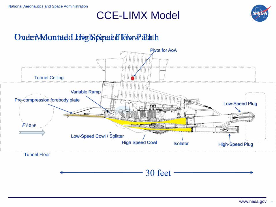
CCE-LIMX Model
Low-Speed Flow Path
(turbine engine)
High-Speed Flow Path
(DMSJ engine)
6
National Aeronautics and Space Administration
www.nasa.gov
CCE-LIMX Model
Pre-compression forebody plate
Isolator High-Speed Plug
Variable Ramp
High Speed Cowl
Low-Speed Cowl / Splitter
Tunnel Floor
Tunnel Ceiling
Pivot for AoA
F l o w
Low-Speed Plug
30 feet
7
Over Mounted Low-Speed Flow Path Under Mounted High-Speed Flow Path
National Aeronautics and Space Administration
www.nasa.gov
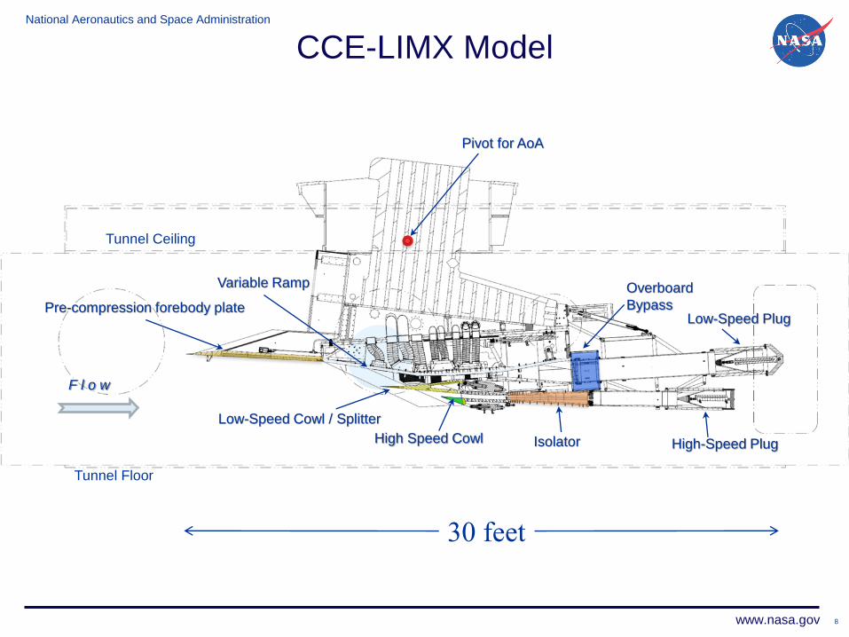
CCE-LIMX Model
Pre-compression forebody plate
Isolator High-Speed Plug
Variable Ramp
High Speed Cowl
Low-Speed Cowl / Splitter
Tunnel Floor
Tunnel Ceiling
Pivot for AoA
Overboard
Bypass
F l o w
Low-Speed Plug
30 feet
8
National Aeronautics and Space Administration
www.nasa.gov
Inlet Unstart Region Inlet Start Region
Throat
Normal Shock
Increased Stability Margin
Increased Performance
Diffuser
CCE-LIMX LSFP Terminology
High mass recovery
High pressure recovery
Low distortion
Low drag
Started Inlet Un
Compressor stall
Combustor flame-out
Causes of Inlet Unstart: Compressor stall
Free stream changes
Airflow Direction
9
National Aeronautics and Space Administration
www.nasa.gov
CCE-LIMX Test Plan
• Phase 1 – Inlet characterization and performance testing
– Static inlet operating points
– Mode transition schedule
• Phase 2 – System identification
– Step response
– Sinusoidal sweep response
• Phase 3 – Controls testing
– Disturbance rejection testing
– Controlled mode transition
• Phase 4 – Propulsion system testing
– Turbine engine for LSFP
– Dual-mode combustor for HSFP
10
National Aeronautics and Space Administration
www.nasa.gov
Guidance Navigation and Control Team
• Develop tools and procedures to streamline:
– Experimental data analysis
– Inlet mode transition controls design
– Controls evaluation
• Simulation models:
– LArge Perturbation INlet (LAPIN)
– Aerosim interactive simulation
– High Mach Transient Engine Cycle Code (HiTECC)
11
National Aeronautics and Space Administration
www.nasa.gov
HiTECC Simulation
• High Mach Transient Engine Cycle Code (HiTECC)
• Simulation package originally developed by
SPIRITECH Advanced Products Inc.
• Demonstrate all modes of operation of a TBCC
propulsion system
– Afterburner, turbine engine, and dual-mode scramjet
– Simulate mode transition sequence of events
• Designed to be generic and modular
– Inlet geometry described using the Mathworks® SimscapeTM
– Fast prototyping of inlet designs
12
National Aeronautics and Space Administration
www.nasa.gov
Thermal Management /Fuel System Models
Control System Hydraulics Model
Turbo Jet Engine Model
Dual Mode Scramjet Model
High Mach Transient Engine Cycle Code (HiTECC)
Propulsion Models
13
National Aeronautics and Space Administration
www.nasa.gov
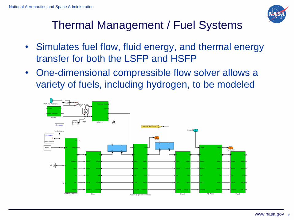
Thermal Management / Fuel Systems
• Simulates fuel flow, fluid energy, and thermal energy
transfer for both the LSFP and HSFP
• One-dimensional compressible flow solver allows a
variety of fuels, including hydrogen, to be modeled
14
2
Pfuel
1
T_ABLiner
V+
-
PS
+-
Tt
VolumeRef
Pt
A
B
Area Out
dens
cp
v isc
v sonic
Tank With Return1
ht
m
A B
ht
m
A B
f(x)=0
PSS
PSS
PsBS
A
AreaA
densA
cpA
v iscA
v sonicA
B
AreaB
densB
cpB
v iscB
v sonicB
Positive Displacement Pump
A
AreaA
densA
cpA
v iscA
v sonicA
B
AreaB
densB
cpB
v iscB
v sonicB
Pipe7
A
AreaA
densA
cpA
v iscA
v sonicA
B
AreaB
densB
cpB
v iscB
v sonicB
Pipe2
A
AreaA
densA
cpA
v iscA
v sonicA
B
AreaB
densB
cpB
v iscB
v sonicB
Pipe
PSS
Res_TF_Pump_wSimscape
FluidReference
Simscape
FluidProperties
G
Rotational Speed
Torque
+
-
R
C
DC Motor
Current
Power Remaing
+
-
Battery
Qpanel Tpanel
A
Area A
dens A
cpA
v iscA
v sonicA
B
Area B
dens B
cpB
v isc B
v sonicB
AB Panel
2
DC Motor Resistance
1Qpanel
National Aeronautics and Space Administration
www.nasa.gov
Hydraulics Model
15
• Simulates the kinematic features of the variable inlet
and nozzle for both flow paths
• Models the dynamic response of the hydraulic fluid
• Models for the power storage and generation for
pumping the hydraulic fluid
3
Relief Valve
2
Tank Supply
1
Tank Return
f(x)=0
Solver
Configuration1
PSS
V P R
Reservoir
PS S
PS SPS S
PS S
PSS
QA
B
Ideal Hydraulic Flow
Rate Sensor2
QA
B
QA
B
Ideal Hydraulic Flow
Rate Sensor
AB
P
Ideal Hydraulic
Pressure Sensor
S A
B
2-Way Directional
Valve
1
Shut Off Valve
National Aeronautics and Space Administration
www.nasa.gov
Propulsion System
• Variable Inlet (P,T,W)
• Gas Turbine (with afterburner)
• Dual Mode Scramjet
• Assume Started Low-Speed and High-Speed Inlets
(No external normal shocks)
16
National Aeronautics and Space Administration
www.nasa.gov
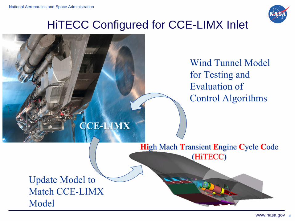
HiTECC Configured for CCE-LIMX Inlet
17
High Mach Transient Engine Cycle Code
(HiTECC)
CCE-LIMX
Update Model to
Match CCE-LIMX
Model
Wind Tunnel Model
for Testing and
Evaluation of
Control Algorithms
National Aeronautics and Space Administration
www.nasa.gov
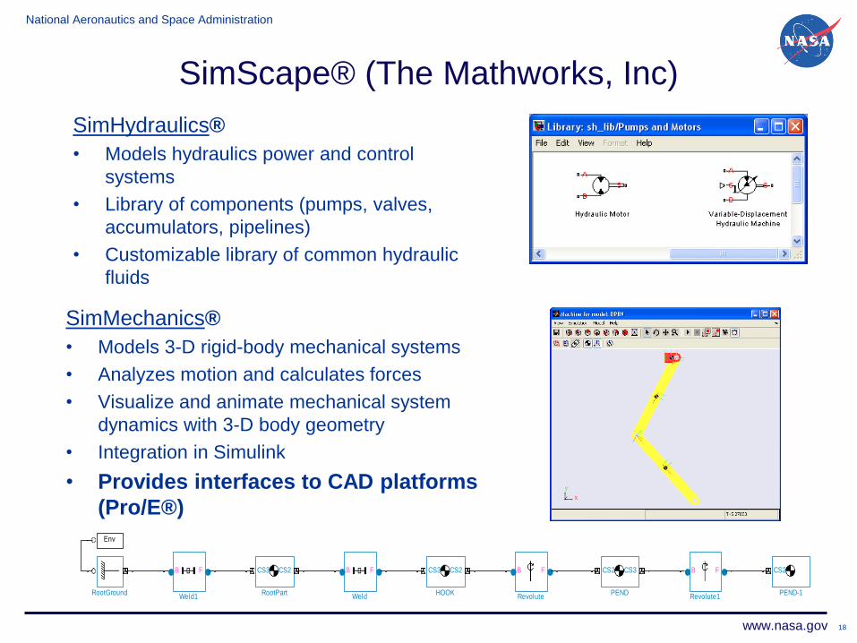
SimScape® (The Mathworks, Inc)
SimMechanics®
• Models 3-D rigid-body mechanical systems
• Analyzes motion and calculates forces
• Visualize and animate mechanical system
dynamics with 3-D body geometry
• Integration in Simulink
• Provides interfaces to CAD platforms
(Pro/E®)
SimHydraulics®
• Models hydraulics power and control
systems
• Library of components (pumps, valves,
accumulators, pipelines)
• Customizable library of common hydraulic
fluids
18
B F
Weld1
B F
Weld
CS3 CS2
RootPartRootGround
B F
Revolute1
B F
Revolute
CS2
PEND-1
CS2 CS3
PEND
Env
CS3 CS2
HOOK
National Aeronautics and Space Administration
www.nasa.gov
CAD Drawing (Pro/E®)
Simulink Model
HiTECC Simulink Model
SimMechanics Link
19
National Aeronautics and Space Administration
www.nasa.gov 20
National Aeronautics and Space Administration
www.nasa.gov
Redesign Geometry, Actuators, and Control
Systems
21
100 150 200
-30
-20
-10
X Position, in
Y P
ositio
n,
inMach 4.0
100 150 200-2
0
2
X Position, in
Are
a E
rror,
%
Mach 4.0
100 150 200
-30
-20
-10
X Position, in
Y P
ositio
n,
in
Mach 3.1
100 150 200-2
0
2
X Position, in
Are
a E
rror,
%
Mach 3.1
100 150 200
-30
-20
-10
X Position, in
Y P
ositio
n,
in
Mach 2.5
100 150 200-2
0
2
X Position, in
Are
a E
rror,
%Mach 2.5
CCE-LIMX HiTECC
National Aeronautics and Space Administration
www.nasa.gov
HiTECC Subsonic Volume Initial Conditions
22
Supersonic
Flow
Subsonic
Flow
No
rmal
Sh
ock
W16 P15
T15 P17
T17 P19
T19 W18
dxdt
National Aeronautics and Space Administration
www.nasa.gov
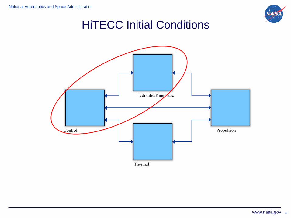
HiTECC Initial Conditions
23
Propulsion
Hydraulic/Kinematic
Control
Thermal
National Aeronautics and Space Administration
www.nasa.gov
HiTECC Initial Conditions
24
Propulsion
Hydraulic/Kinematic
Control
Thermal Control
Switch
Hydraulic/Kinematic
Sw
itch
National Aeronautics and Space Administration
www.nasa.gov
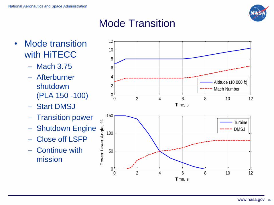
Mode Transition
• Mode transition
with HiTECC
– Mach 3.75
– Afterburner
shutdown
(PLA 150 -100)
– Start DMSJ
– Transition power
– Shutdown Engine
– Close off LSFP
– Continue with
mission
25
0 2 4 6 8 10 120
2
4
6
8
10
12
Time, s
Altitude (10,000 ft)
Mach Number
0 2 4 6 8 10 120
50
100
150
Time, s
Pow
er
Lever
Angle
, %
Turbine
DMSJ
National Aeronautics and Space Administration
www.nasa.gov
Mode Transition
• During mode
transition,
propulsion system
must produce
enough thrust to
keep vehicle at
Flight Condition.
• TBCC produces
thrust between the
min/max bounds
26
0 2 4 6 8 10 120
2000
4000
6000
Time, sT
hru
st,
lbf
Turbine
DMSJ
0 2 4 6 8 10 120
2000
4000
6000
Time, s
Tota
l T
hru
st,
lbf
National Aeronautics and Space Administration
www.nasa.gov
Mode Transition Plots
27
0 2 4 6 8 10 120
0.2
0.4
0.6
0.8
Time, s
Pre
ssure
Ratio
0 2 4 6 8 10 12182
184
186
188
190
Time, s
Shock P
ositio
n,
in
National Aeronautics and Space Administration
www.nasa.gov
CCE-LIMX Model
Pre-compression forebody plate
Isolator High-Speed Plug
Variable Ramp
High Speed Cowl
Low-Speed Cowl / Splitter
Tunnel Floor
Tunnel Ceiling
Pivot for AoA
Overboard
Bypass
F l o w
Low-Speed Plug
28
• Testing candidate mode transition and shock position
control algorithms before implementation
• Compare performance of HiTECC to wind tunnel data
model validation
National Aeronautics and Space Administration
www.nasa.gov
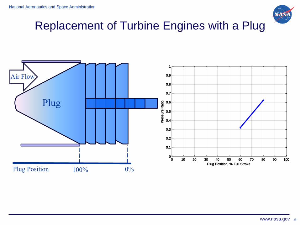
Replacement of Turbine Engines with a Plug
29
100% 0%
Plug
Air Flow
Plug Plug Plug Plug
Plug Position
0 10 20 30 40 50 60 70 80 90 1000
0.1
0.2
0.3
0.4
0.5
0.6
0.7
0.8
0.9
1
Plug Position, % Full StrokeP
ressure
Ratio
0 10 20 30 40 50 60 70 80 90 1000
0.1
0.2
0.3
0.4
0.5
0.6
0.7
0.8
0.9
1
Plug Position, % Full StrokeP
ressure
Ratio
0 10 20 30 40 50 60 70 80 90 1000
0.1
0.2
0.3
0.4
0.5
0.6
0.7
0.8
0.9
1
Plug Position, % Full StrokeP
ressure
Ratio
National Aeronautics and Space Administration
www.nasa.gov
Addition of the Cold Pipe Volume
W16
P15
T15 P17
T17 P19
T19
W18
Supersonic Flow
30
National Aeronautics and Space Administration
www.nasa.gov
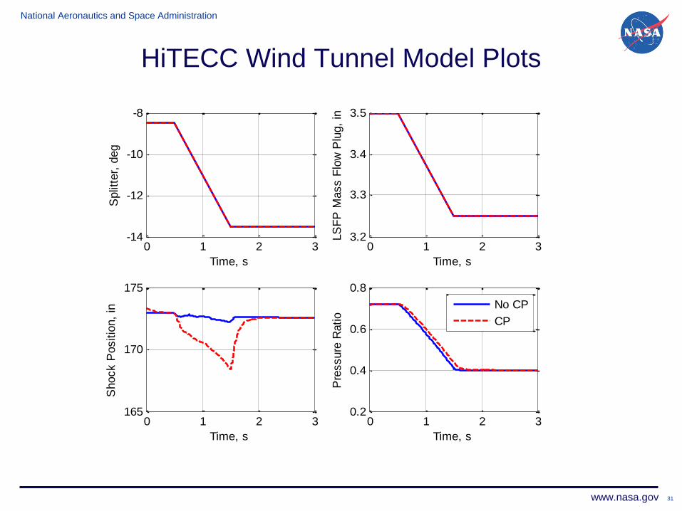
HiTECC Wind Tunnel Model Plots
31
0 1 2 3-14
-12
-10
-8
Time, s
Split
ter,
deg
0 1 2 33.2
3.3
3.4
3.5
Time, s
LS
FP
Mass F
low
Plu
g,
in
0 1 2 3165
170
175
Time, s
Shock P
ositio
n,
in
0 1 2 30.2
0.4
0.6
0.8
Time, s
Pre
ssure
Ratio
No CP
CP
National Aeronautics and Space Administration
www.nasa.gov
HiTECC Wind Tunnel Model Plots
32
0 0.5 1 1.5 2 2.5-14
-12
-10
-8
Time, s
Split
ter,
deg
0 0.5 1 1.5 2 2.50
2
4
6
Time, s
Bypass G
ate
, sq in
0 0.5 1 1.5 2 2.5165
170
175
180
Time, s
Shock P
ositio
n,
in
0 0.5 1 1.5 2 2.5
0.4
0.5
0.6
0.7
Time, s
Pre
ssure
Ratio
No CP
CP
National Aeronautics and Space Administration
www.nasa.gov
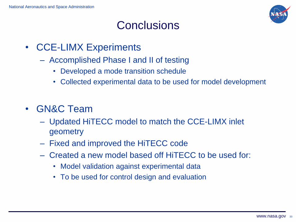
Conclusions
• CCE-LIMX Experiments
– Accomplished Phase I and II of testing
• Developed a mode transition schedule
• Collected experimental data to be used for model development
• GN&C Team
– Updated HiTECC model to match the CCE-LIMX inlet
geometry
– Fixed and improved the HiTECC code
– Created a new model based off HiTECC to be used for:
• Model validation against experimental data
• To be used for control design and evaluation
33
National Aeronautics and Space Administration
www.nasa.gov
Future/Ongoing work
• Compare HiTECC to captured wind tunnel data.
Results will be published and presented at the 2012
JANNAF Conference in Monterey, CA, 12/2012.
• Use HiTECC to design shock position control
algorithms. Results will be published and presented