NASA CR 132 454 June 14, 1974 HYPERSONIC RAMJET EXPERIMENT PROJECT PHASE I COMPUTER PROGRAM DESCRIPTION RAMJET AND SCRAMJET CYCLE PERFORMANCE By: Robert J. Jackson Tennyson T. Wang (NASA-CR-13245 4 ) HYPERSONIC RAHJET N74-2921 4 EXPERIMENT PROJECT. PHASE 1: COMPUTER PROGRAM DESCRIPTION, RAMJET AND SCRAMJET CYCLE (AiResearch Mfg. Co., Los Angeles, Unclas Calif.) p HC $3.25 . CSCL2-lA . G3/28 43356 A I' Prepared under Contract No. NASI-5116 AiResearch Manufacturing Company, Division of The Garrett Corporation for NATIONAL AERONAUTICS AND SPACE ADMINISTRATION -4 https://ntrs.nasa.gov/search.jsp?R=19740021101 2018-07-05T15:34:17+00:00Z
Inlet calculations.- Flight conditions are specified in terms of flight
Mach number, ambient pressure, and ambient temperature.
As shown above, station 2 is the interface between the engine inlet and
the combustor. The program calculates the one-dimensional, equilibrium prop-
erties of the inlet air at station 2 corresponding to (I) assigned flow area
or Mach number, (2) inlet losses, and (3) inlet spillage (mass-flow ratio).
Note that station 2 is primarily the combustor inlet, not necessarily the
engine-inlet throat (minimum flow area).
The inlet losses are stipulated in terms of the kinetic energy effi-
ciency, 1KE' or the rise in enthalpy, AH', from conditions corresponding to
free-stream pressure and entropy to conditions corresponding to free-stream
pressure and combustor-inlet entropy.
The inlet spillage is given as the ratio of capture area to cowl area.
Data printed out at station 2 include pressure, temperature, enthalpy,
entropy, molecular weight, c , y, Mach number, ratio of flow area to inlet
capture area, velocity, tota pressure recovery, vacuum specific impulse, and
fuel port area. Also, the equilibrium Mol fractions of the working-fluid
constituents are printed.
2
Combustor calculations.- The combustor calculations yield the one-
dimensional, equilibrium properties of the combustor-exit flow, engine
.station 3. The following conditions and data must be input:
a. Mode of combustion, supersonic or subsonic.
b. Fuel equivalence ratio.
c. Fuel storage temperature and fuel temperature at injection ports.
d. Fuel injection velocity.
e. Ratio of combustor wall area to inlet flow area.
f. Combustor wall-friction drag coefficient.
g. Assigned combustor exit condition (pressure, Mach number,or area).
h. Combustion chemical efficiency, the ratio of reacted fuel to fuel
supplied.
The input provision for two valties of fuel temperature is necessary for
analysis of regenerative ly-cooled combustors. For energy calculations, the
fuel enthalpy must be based on the temperature of the fuel prior to its
introduction into the cooling circuits; however, sizing of fuel injection
ports must be based on the actual fuel injection temperature and velocity.
The equilibrium thermodynamic properties of the combustion products are
calculated by the procedure described in ref. I.
Calculation of combustor exit momentum requires, for cases other than
constant-area or constant-pressure combustion, evaluation of combustor-wall
pressure forces. In general, this is done by assuming that the effective
combustor static pressure is the average of the combustor inlet and discharge
static pressures. However, where appropriate, the effective combustor static
pressure can be taken to be:
- P2 + KP3 (I)
s K+ I
By formula (I), the effective combustor static pressure can be made to
approach the combustor exit pressure, P3 , as K is allowed to increase. Use
of this procedure would be based on detailed investigation of the combustor
pressure distribution.
The combustor wall-friction drag coefficient, CD, is defined by:
FD = C A w (2)
where FD is the wall-friction drag force, Aw the wall area, and q the average
of combustor inlet and discharge dynamic pressures.
The flow properties printed out at station 3 include the parameters
printed for station 2, the area ratio, A3/A 2, plus engine performance param-
eters: Net internal thrust, thrust per unit of capture area, fuel specific
impulse, and thrust coefficient.
Nozzle calculations.- An isentropic, equilibrium, real-gas expansion
from the combustor exit to the nozzle exit is calculated. For subsonic com-
bustion, the first line of output subsequent to the combustor exit refers to
the nozzle sonic throat (this is omitted for supersonic combustion). Subse-
quent lines of output correspond to assigned values of combustor-exit-to-
nozzle pressure ratio, to full expansion to ambient pressure, and finally, to
the assigned nozzle exit condition (assigned area or pressure). For super-
sonic combustion, the ratio of nozzle area to combustor exit area is printed;
for subsonic combustion, the ratio of nozzle area to nozzle sonit throat is
printed out.
Nozzle losses are accounted for by a velocity or stream-thrust coeffi-
cient, CS :
V RT
Iva c q 4 V (3)
CS- Ivac, ID V + )ID
where the ideal values are calculated for isentropic, equilibrium nozzle
expansion. The coefficient, CS, is evaluated from detailed nozzle investi-
gations to account for kinetic, friction, and divergence losses.
To calculate the net thrust for flight conditions where inlet spillage
must be considered, an additive drag coefficient, CDA, is employed. This
drag coefficient is defined as follows:
FDA = CDA q AC (4)
where FDA is the drag force caused by inlet spillage, qo is the free-stream
dynamic pressure, and AC is the cowl area. Values of CDA have been
correlated with flight Mach number and inlet mass-flow ratio.
OPERATING INSTRUCTIONS
Hardware requirements.-
a. IBM 7090 or 7094 computer with 32K core.
b. Data Channels and tape units for the software.
4
c. No on-line printer and punch.
d. Peripheral equipment for card-to-tape, tape-to-printer, and tape-to-
punch as required by standard IBM system.
e. It is assumed that standard keypunch and verifier machines, cardreaders, and printers are used; therefore, these have not beenspecified.
Software requirements.-
a. IBSYS Operal.inl System Tape Version 12
(I) 'Basic Monitor (IBSYS) Version 4
(2) Processor (IBJ0B) Version 4
(3) Assembly Language (MAP) Version 4
(4) Assembly Language (FTC) Version 4
(5) Loader (IBLDR) Version 4
b. The Fortran IV I/0 Library Subroutines
Tape usage.- The standard Fortran input/output configuration, asdescribed in IBM 7090/7094 IBSYS Operating System: IBJOB Processor, FormC28-6275, is used for the logical tape unit designation and the file specifi-cations are as follows.
The logical tape unit 5 and 6 are used as input and output, respectively.No intermediate storage tape is used.
5
Deck set-up.-
a. $JOB
b. $EXECUTE IBJbB
$IBJbB (Options)
Program
decks
End of File (7,8 Punch in Col. I)tData (Thermodynamic data anddecks \program input data )
4End of File (Same as above)
For a description of these control cards see:
(IBM 7090/7094 Operation Systems Basic Monitor (IBSYS),
Form C28-6248)
(IBM 7090/7094 IBSYS Operating System IBJh B Processor,Form C28-6275)
STOP
c. $IBSYS $IBSYS
d. $STOPEND-0F-FILEd. $ST P "
PROGRAM INPUT DATA
THERMODYNAM IC DATA
END-O F FIL E
S- * PROGRAM DECK CONSISTSPROGRAM DECK OF MAIN PROGRAM MAIN
IBJB AND FIVE SUBROUTINES:
$SEXECUTE IBJOB CRE2,, MATRIX
-8JOB GAUSSALEO A-I 71-
Deck Set-up A- 712
6
Timing.- The computer time for each case depends upon the number of
iterations. It takes approximately one minute per case.
Multiple cases.- The cases may be stacked for one computer run.
Input Description
Format.-
Card I Field Description
I I Reference case number (usually "I")
914 2 "O" means subsonic combustion; "I".meanssupersonic combustion.
3 Blank
4 Blank
5 Number of nozzle stations for which data are
printed out.
6 Number (0 to 25) of nozzle pressure ratios for
schedule of assigned nozzle pressure ratios.
7 Blank
8 "0" means normal printout. "I" means"debug printout".
9 Number of cases (I to 15).
2 I "0." means specified combustor pressure ratio."-I." means specified combustor exit Mach
8FIO.0 number. "I." means specified combustor arearatio.
2 Ae/AC, ratio of nozzle exit area to cowl area.
Blank if nozzle pressure ratio is specified.
3 A2/AC, ratio of combustor inlet area to cowl
area. Blank if combustor inlet Mach number is
specif led.
7
Card Field Description
2 4 M2, combustor inlet Mach number. Blank if
A2/AC is specified.8FIO.0
5 Pe/PO, ratio of nozzle exit pressure to
ambient pressure. Blank if A /AC is
specified.
3 I cos of fuel injection angle
8F10.O 2 AC, cowl area, sq ft
4 I Aw/A2, ratio of combustor wall area to com-
bustor inlet area.
5 I Ambient pressure, atm.
8FIO.0 2 Ambient temperature, OK
3 Flight Mach number
4 Blank
5 Additive drag coefficient
6 I TIKE., inlet kinetic energy efficiency, or
(by pre-fixing a minus sign) the enthalpy8F10.0 rise between free-stream pressure, entropy
conditions and conditions corresponding to
free-stream pressure and combustor-inlet
entropy.
2 A0/AC, ratio of inlet capture area to cowl
area (i.e., mass-flow ratio).
3 Ae, e m/AC, eff ratio of geometric nozzle
exi aorea to effective nozzle exit area (toaccount for boundary-layer growth).
4 CS, nozzle velocity coefficient, ratio of Ivacto Ivac calculated with no nozzle losses.
8
Card Field Description
6 5 Temperature of fuel at fuel-injectionnozzles, OK.
7 I , equivalence ratio
8FIO.O 2 c, combustor chemical efficiency, ratio (byweight) of reacted fuel to fuel supplied.
3 Vf, fuel inlet velocity, ft per sec.
4 Temperature of fuel corresponding to storageconditions.
5 Assigned combustor pressure ratio, area ratio,or exit Mach number, as applicable.
6 Combustor wall-friction drag coefficient.
Cards 8-10 Up to 25 values of nozzle pressure ratio, PN/P3.(Optional) Used when sixth field of card I is non-zero.
8FIO.O
The "reference case" comprises a complete set of the above seven datacards. Up to 14 additional cases, representing changes in any or all of thevariables entered on Cards 5, 6, and 7, can be handled for constant values ofthe data on cards I to 4. For each of these additional cases, a set of cards5, 6., and 7 is added to the input-card deck. However, only the values whichdiffer from those of the reference case are punched. For example, to run arange of M3, two blank cards and a card punched with the appropriate value inthe fifth field are added to the input-card deck for each new value of M3.
Any number of.the above input-data-card decks can be stacked for a com-puter run.
Table I presents a computer input data format with program internal
symbols.
Definitions.-
Additive Drag = CDA (1/2 p0 Vo02 ) AC
Combustor Wall-Friction Drag = Cd q A
where q = 1/2 [(1/2 p2 V22 )+ (1/2 p3 V3
2 )]
A = Combustor internal wetted areaw
9
TABLE I
IBM COMPUTER PROGRAM INPUT FORM
IBM MACHINE PAGE NO.
DATE PROGRAM NO.
PREPARED BY PERM. NO. EXT.
EST. RUN TIME CHARGE NO.
COMMENTS INPUT DATA FORMAT WITH PROGRAM INTERNAL SYMBOLS
I 10 II 20 21 30 31 40 4I 50 51 60 6! 70 71 80
FORMAT 914
CIONST 2EIAR A2AC VMACH2 2PAM
COSTH AC _WL
AW2
(PCC , (TCC) (VMACHO), (CDO),
(ANKE) (AOAC), (AEA4), (CVN) (TTFUEL),
(PHI), (DELTAH), (VF), (TFUEL), (P3P2), (CD),
FORMAT 8F0O.O
(rc)N (TCC)N (VMACH0)N (CDO)N
(ANKE)N (A0AC)N (AEA4)N (CVN)N (ITFUEL)N
(PHI)N (DELTAH)N (VF)N (TFUEL)N (P3P2)N (CD)N
WHERE N-ICASES
SAIRESIARCH MANIfACIURIN6 WVISION
I0
Output Description
Input data.- The input data values for a run are printed out prior to
and separate from the calculated results.
Inlet calculations.- First line (below headings):
PO - Free stream pressure, atm
TO - Free stream temperature, OK
ETA KE - KE
MACHO - Flight Mach number
MACH2 - Assigned combustor inlet Mach number (if applicable)
PHI - Equivalence ratio
A2/AC - Assigned ratio of combustor inlet area to cowl area (if
applicable)
VO - Flight velocity
HOI - Enthalpy (cal per gm) corresponding to free stream pres-
sure and combustor inlet entropy.
AO/AC - Ratio of capture area to cowl area.
AO - Capture area, sq ft
The second and subsequent lines of printout (excluding the composition
data) are the values calculated for each iteration to the applicable com-
bustor inlet condition. The converged values are presented in the last such
line of data. Units of enthalpy and entropy are cal per gm and cal ger gm-K,
respectively, where enthalpy is assigned the value of zero at 298.15 K.
PO/P -Ratio of free-stream pressure to combustor inlet pressure.
P ATM - Combustor inlet pressure, atm
MACHNO - Combustor inlet Mach number
A/AO - Ratio of combustor inlet area to capture area
The composition data are the mol fractions of each constituent.
II
Finally, the inlet total pressure recovery is the calculated ratio ofcombustor inlet total pressure to the free-stream total pressure; fuel inletport area is given in sq ft; and IVAC is the momentum parameter, vacuum
V PAspecific impulse, + -P-, sec.
Combustor exit calculations.- The heading stipulates the type of nozzlecalculation; the second line gives the amount of fuel in terms of threeparameters: (I) the air-to-fuel mass ratio, (2) the equivalence ratio, and(3) the fuel-to-mixture mass ratio.
Combustor exit data are printed in two lines. Parameters not already
identified are the following:
A/A2 - Ratio of combustor exit area to combustor inlet area.
T/AO - Net thrust per unit of capture area, lb per sq ft.
SP IMP - Net thrust per unit of fuel flow, sec
THRUST - Net thrusty lb
IVAC - Vacuum specific impulse, sec
THRUSTCT - Thrust coefficient, qAc
qo0AC
The second line of output (following composition data), in the case ofsubsonic combustion, is the nozzle throat calculation. Subsequent lines ofoutput comprise (1) stipulated nozzle pressure ratios (per word 5 on card I)and (2) results of each iteration to the specified nozzle exit condition.For subsonic combustion, the area ratios, A/A3, are actually ratios of nozzlearea to throat area. In the case of supersonic combustion, there is no nozzlethroat calculation, and A/A3 is actually the ratio of nozzle area to com-bustor exit area.
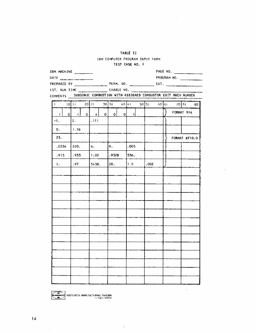
Test Case
The following test cases are used to illustrate the input and the outputof the program:
a. Subsonic combustion with assigned combustor exit Mach number.
b. Supersonic combustion with assigned combustor exit Mach number.
c. Supersonic combustion with assigned combustor area ratio.
12
The IBM input forms for these cases are presented in tables II, III, and
IV.
The outputs of the test cases are forwarded under separate cover.
REFERENCE
I. Zeleznik, Frank J., and Fordon, Sanford, "A General IBM 704 or 7090
Computer Program for Computation of Chemical Equilibrium Composition,
Rocket Performance, and Chapman-Jouget Detonations", NASA TN D-1454
(1962).
December, 1965AiResearch Manufacturing Company
/Division bf the Garrett Corporation
Los Angeles,. California
13
TABLE II
IBM COMPUTER PROGRAM INPUT FORM
TEST CASE NO. I
IBM MACHINE PAGE NO.
DATE PROGRAM NO.
PREPARED BY PERM. NO. EXT.
EST. RUN TIME CHARGE NO.
COMMENTS SUBSONIC COMBUSTION WITH ASSIGNED COMBUSTOR EXIT MACH NUMBER
I 10 11 20 21 30 31 40 4I 50 51 60 61 70 71 80
0JI0j4 07 _FORMAT 914-I. 2. .I1
0. I.76
35. FORMAT BFIO.O
.0334 220. 6. 0. .005
.915 .955 1.00 .9528 556.
I. .97 5450. 20. I1.0 .002
SAIRES[ARCH MANUiFACIURING DIVISION
14
TABLE III
IBM COMPUTER PROGRAM INPUT FORM
TEST CASE NO. 2
IBM MACHINE PAGE NO.
DATE PROGRAM NO.
PREPARED BY PERM. NO. EXT.
EST. RUN TIME CHARGE NO.
COMMENTS SUPERSONIC COMBUSTION WITH ASSIGNED COMBUSTION EXIT MACH NUMBER
1 10 II 20 21 30 31 40 1I 50 51 60 61 70 71 80
II I II 0 4l 0 O0 0 21FRA 1_ _ } FORMAT 914
-I. 2.0 .11I
0. 1.76
35.0
.0334 220. 6.0 0. .025 FORMAT 8FIO.O
.96 .82 1.0 .9696 556.
.6 .97 5450. 20. 1.2 .002
BLANK CARD
BLANK CARD
I.
I AIRESEARCHI MANUFACIIJRING DIVISION
15
TABLE IV
IBM COMPUTER PROGRAM INPUT FORM
TEST CASE NO. 3
IBM MACHINE PAGE NO.
DATE PROGRAM NO.
PREPARED BY PERM. NO. EXT.
EST. RUN TIME CHARGE NO.
COMMENTS SUPERSONIC COMBUSTION WITH ASSIGNED COMBUSTOR AREA RATIO
I 10 II 20 21 30 31 40 A1 50 51 60 61 70 71 80
4 0 FORMAT 914
1.0 2.0 .111
0. 1.76
2.
.024 222. 7.0 0. 0.
.955 1.0 1.0 .93 500.
1.0 I. 2000.0 20.0 2.0 .08 FORMAT 8FIO.0
BLANK CARD
BLANK CARD
2.2
BLANK CARD
BLANK CARD
5.0
SAIRESEARCH MANUFACTtRING ('IVISION
16
Reference: (i Aipscarch npoort AP-1O01-1, Computcrprogjra; Description, Ramjet pnd Scrarmjot
Cycle Performanco conducted under t.SA
Contract NiASl-5116
Revised Cycle Performance Program (from Referonco one) including:
0) Computer tapeb Program listingc) Sample calculationd Input for at/instructionsa SampiG input cards
The revised cycle pcrformanco from the referenced report incorporates
the following modfications:
l,. -The progrrm was modified in order to morc accurately accou0:
for the pressure distribution along the ,ul$i-stascd coibustor
walls. This can n.., be cco~apl.ished by sto',cinj the input
data for each stage, spcify.ing the co.,iutor area rctiO and
equivale't pro;sure, z.)-.e. WojiInq consant . r c.-ch .s.t,:e.
Th prog rm V1 1c octo thc c nsi-zta~o prc?51=1 Cs a
stage problem by using the results froin previous stacs.
2. The monntumf-continulty equation in this program was
modified to a third otder algcbralc equation in order
to more accurately solvo for tho velocity at the com-
bustor exit.
3. Because the dynamic pressure distribution Is not linear
along the multi-stage combustor, the -viscous drag cal-
culation was modified by using the averaged value of q
.o.cah.stago rather than using the avaragccl value of
q for the overall combustor as done previously.
.Reproduced from
bsatalable copY.
... . .A r.DI\'t OJN OF IM: GAr A fi, - c - -r c r, /TiON
.. . A-. 1 45 0 1 SL PULVF; CIA FioUL.EVA *C) LF " C. L , F ; ALIr nI NIA c9r000
T E E PLEPHDNE: 12131 77t-101U. 670*0131 * CtAILF UARHIETTAIf LOS ANtGELES
In reply refer to:SfJD-S267-05l0
10 1may 1968
National Aeronoutics and Space AdministrationLangley Research CenterilTHmnpton, Virginia 23365
Attention: 1,'r. K. D. AlbertContrect Admninistrator
Subj ect; Hlyper son Ic Research Enr in;e ProjectNASA Contract NASIl-666Subriittal of Computer Tape
Reference: (1) AIP.esearch Report AP-1001-1, Co; p uterPro0 gram Description, i, mj e: andr Scra:mjetCycle Performance conducted under .ASAContract NASl-5116
Gentlemen:
The following information is submitted as rcquested in telocon ofMay 35, 1968 between H.F. Potthest and K.D. Albort.
Revised Cycle Performance Program (from Reference one) Includiagj:
a) Computer tapeb) Program listing
c Samnple calculaitiond Input foriat/instructions
S Samiple input cards
The revised cycle performance from the refireniced report incorporatesthe following modf!catons:
I The prograrm was modifiud i; order to more accurately accountfor the pressure ditr ... on along thG r-,ul i-staed comustorwalls. This can nW be. accooplished by stockin, the inpu*.data for eich sta$e, specifying thic combu,;tor area r-Ai aindequivalent pressurc., ahd weiohing coiistant iK for onch sta;e-.The program will executiu the iu I Li- .ao prWl I z;a a i nrl e-stage problem by using the results froi previous staSes.
NASA Langley Research Center SRJD-C267-05O0Attention: tr. K. D. Albert Page .2-
2. The rnomentum-continulty equation in this program wasmodified to a third order algebralc equation in orderto more accurately solve for the velocity at the corn-bustor exit.
3. Because the dynamic pressure distribution is not linearalong the multi-stage combustor, the viscous drag cal-culation was modified by using the averaged value of q.Ot ecach .s.tage rather than usirng the averaged value ofq for the overall combustor as dorine previously.
Very truly yours,
AIRESEARCH L'ANUFACTURI NG CO.PANYA Division of The Garrett Corporation
R. J. DunnProgram AdministratorAdvanced ProPulsicn Engines Sales
RJD/lkErnclosure
CC: D. Arganbrlght - DCASOM. Craig - Garrett Sales lHampton
INPUT DESCRIPTION
Card Field Description
SI Reference case number "I" for first, stage"15" for subsequent stages
(914) 2 "0" means subsonic combustion; "I" means
supersonic combustion
3 Blank
4 Blank
5 Number of nozzle stations for which dataare printed out
6 Number (0 to 25) of nozzle pressure ratiosfor schedule of assigned nozzle pressurerat los
7 Blank
- 8 "0" or "I" means normal printout
"2" chemical equilibrium calculation
"3" thermodynamic data for species
"4" iteration for combustor exit velocityand skin friction'coefficient
"5" means both "3" and "4"
"6" means all "2", "3" and "4"
9 Number of cases (I to 15)
2 I "0" means specified combustor pressure ratio
(8FIO.0) "-I" means specified combustor exit Mach No.
"I" means specified combustor area ratio
2 Ae/Ac, ratio of nozzle exit area to cowl
area. Blank if norzle pressure ratio isspecified
3 A2/Ac, ratio of combustor inlet area to
cowl area. Blank if combustor inlet Machnumber is specified - D0
INPUT DESCRIPTION (Coit inued)
Card Field Description
Z 4 M2 , combustor inlet Mach number. Blank
(FI.O0') if A2/Ac is specified
5 Pe/Po, ratio of nozzle exit pressure to
amnbient pressure. Blank if A2/Ac isspecified t. ? .^ e 1
* 3 I CosO, 0 is the fuel injection angle withrespect to the horizontal axis.
(8FI0.0) (e.g., "0." for normal injection)
2 Ac, cowl area, sq.ft
.4 I A/vIA 2, ratio of combustor wetted area to
(8FI0.0) combustor inlet area
2 K1, constant for evaluating the average
pressure acting on the first stagecombustor walls. P = (P2 + Ki P3 )/(i + KI)
5 I Ambient pressure, atm
(SFIO.0) 2 Ambient temperature, OK
3 Flight Mach number
4. Blank
5 Additive drag coefficient
6 I 'KE' inlet kinetic energy efficiency, or
(8FIO.0) (by pre-fixing a minus sign) the enthalpyrise between freestream pressure, entropyconditions and conditions corresponding tofreestream pressure and combuqtor-inletentropy
2 Ao/Ac; ratio of inlet capture area to
cowl area (i.e., mass flow ratio)
3 Ae, geom/Ac, eff., ratio of geometric nozzle
exit area to effective nozzle exit area (toaccount for boundary layer growth) p1
INPUT DESCRIPTION (Continued)
Card Field Description
4 Cs, nozzle velocity coefficient, ratio
(6rFo, O) of Ivac to the Ivac calculated with nonozzle losses
5 Temperature of the fuel at fuel-injectionnozzle, OK
7 I q, equivalence ratio
(8F10.0) 2 77c , combustor chemical efficiency, ratio
(byweight) of reacted fuel to fuel
supplied
3 Vf, fuel inlet velocity, ft per sec.
4 Temperature of fuel corresponding tostorage conditions , .
5 Assigned combustor area ratio, pressure( ratig,, or exit Mlach number, as applicable
6 Combustor skin-friction coefficient.(a guessed value for multi-stage run)
8 1 K2, constant determining the effective
(8FIO.0) pressure acting on the second stagecombustor wall
2 The ratio of the first stage exit area /to the first stage combustor entrance area
3 The ratio of the first stage exit pressureto the first stage combustor entrance pressure
4 Skin-f'riction drag force acting on thefirst stage, lbf
5 Ratio of the first stage combustor wetted,rea to the first stage combustor entrancea rea
(Blank for third stage run)
6 Second stage combustor skin-frictioncoefficient "
(Blank for third stage run)
INPUT DESCRIPTION (Continued)
Card Field Description
7 The dynamic head of the flow at the exitof the first stage, psia
(Blank for third stage run)
9 K3, constant determining the effective
(8FIO.O0) pressure acting on the third stagecombustor wall
2 The ratio of the second stage exit areato the first stage combustor entrance area
3 The ratio of the second stage exit pressureto the first stage combustor entrance pressure
4 Skin-friction drag force acting on thesecond stage combustor, lbf
5 Ratio of the firs.t and second stagecombustor wetted area to the first stage
.combistor entrance area
6 Third stage combustor skin-frictioncoefficient
7 The dynamic head of the flow at the exitof the second stage, psia