HyperWorks Solvers 12.0.210 Release Notes HyperWorks Solvers is a collection of finite element and multi-body dynamics solvers for structural, fluid- dynamics and systems simulation. These solvers can be employed for simulation driven design as well as design optimization. OptiStruct Design and optimization software using finite elements and multi-body dynamics RADIOSS Finite element solver for linear and nonlinear problems MotionSolve Multi-body dynamics solver AcuSolve General purpose finite element computational fluid dynamics (CFD) solver HyperForge Solver New solver targeted for extrusion related open die forging applications HyperXtrude-RTM Solver Finite element based solver for analysis and design of resin infusion processes With the 12.0.210 release, a renaming of our structural solver products has taken place in order to accommodate the growing trend of applying optimization technologies more intensively in the product development process, instead of just single run analysis. Moving forward, our structural and thermal analysis and optimization product for linear and non-linear events will be called OptiStruct; this includes analysis disciplines such as linear and non-linear statics, noise and vibrations and thermal analysis. Our product for highly-nonlinear, typically transient events such as crash, impact, forming or blast analysis will be RADIOSS. Both codes are developed with a strong focus on the above mentioned disciplines, and will continue to leverage technology mutually. OptiStruct will continue to leverage the widely used bulk data input format, and RADIOSS will continue to use the well suited block format. Moving forward, OptiStruct will also serve as the general framework for optimization involving multiple physics including CFD and FSI with AcuSolve and multi-body dynamics with MotionSolve, and will also offer API to integrate additional solvers and solutions within a general multi-model framework.
Transcript
HyperWorks Solvers 12.0.210 Release NotesHyperWorks Solvers is a collection of finite element and multi-body dynamics solvers for structural, fluid-dynamics and systems simulation. These solvers can be employed for simulation driven design as well as design optimization.
OptiStruct Design and optimization software using finite elements and multi-body dynamicsRADIOSS Finite element solver for linear and nonlinear problemsMotionSolve Multi-body dynamics solverAcuSolve General purpose finite element computational fluid dynamics (CFD) solverHyperForge Solver New solver targeted for extrusion related open die forging applicationsHyperXtrude-RTM Solver
Finite element based solver for analysis and design of resin infusion processes
With the 12.0.210 release, a renaming of our structural solver products has taken place in order to accommodate the growing trend of applying optimization technologies more intensively in the product development process, instead of just single run analysis. Moving forward, our structural and thermal analysis and optimization product for linear and non-linear events will be called OptiStruct; this includes analysis disciplines such as linear and non-linear statics, noise and vibrations and thermal analysis. Our product for highly-nonlinear, typically transient events such as crash, impact, forming or blast analysis will be RADIOSS. Both codes are developed with a strong focus on the above mentioned disciplines, and will continue to leverage technology mutually. OptiStruct will continue to leverage the widely used bulk data input format, and RADIOSS will continue to use the well suited block format.
Moving forward, OptiStruct will also serve as the general framework for optimization involving multiple physics including CFD and FSI with AcuSolve and multi-body dynamics with MotionSolve, and will also offer API to integrate additional solvers and solutions within a general multi-model framework.
OptiStruct 12.0.210 ReleaseThe 12.0.210 release of OptiStruct is yet another functionality-rich release. This release features the support of frequency dependent material properties. Additionally, the ADJUST capability has been added to the contact formulation to remove initial penetrations. Some key highlights of the 12.0.210 release are listed below.
• The ADJUST option is available to remove initial penetration in contact
• Fast Parallel Solver for Large Modal Frequency Response Problems
• Frequency Dependent Material Properties can be used for Direct Frequency Response Analysis (Beta)
• Gasket Material Properties can Now be Temperature Dependent
• Thermal Conduction Based on Contact Surface Opening Distance and Closed Pressure
• Thin Bending Shell Elements can Now be Automatically Converted to Membrane Elements
• SPCFORCE and GPFORCE can Now be Used as an Optimization Responses
Contents
Stiffness, Strength and Stability
The ADJUST Option is Available to Remove Initial Penetration in Contact
Bolt Pretension Forces are Now Written to the ASCII .pret File
Gasket Material Properties can Now be Temperature Dependent
Gasket Transverse Shear Modulus can be Specified as Stress/Displacement or Force/Area Data
Gasket Tension Stiffness can be Specified as a Stabilization Coefficient or the Direct Tension Modulus
The Thermal Field From the Last Time Step of a Transient Heat Transfer Analysis can be Used for the Thermal Load
Solid Element Properties Expanded to Support Navier Stokes Viscosity and an Advanced Tangent Matrix Estimation
Composite Element Material MATX25 Enhanced to Support Failure Based on the Ratio of the Number of Failed Layers to the Total Number of Layers
Force-Deflection Curve Output from Snap Through Analysis
OTIME can be Used in Transient Heat Transfer Analysis
Thermal Conduction Based on Gap Opening Distance
Thermal Conduction Based on Contact Surface Opening Distance and Closed Pressure
New Parameters
Enhanced Subcase Information Entries
New Bulk Data Entries
Enhanced Bulk Data Entries
Highlights of the
Noise and Vibrations
Material Properties can be Frequency Dependent in Direct Frequency Response Analysis (Beta)
Fast Parallel Solver for Large Modal Frequency Response Problems
EIGRA (AMSES) Eigenvalue Calculation Time Reduced
A File to Allow Optimization of CMS Super Elements can be Generated
Sets of RIGID Elements can now be Specified with the Bulk Data SET Data
EIGRA can Handle Much Larger Problems
Run Time and Disk Space Usage Decreased When GPFORCE and MPCFORCE Output is Requested for Frequency Response and Transient Analysis
The Output From Complex Eigenvalue Analysis can be Reduced by Only Outputting the Unstable Modes
The Creation Time of CDS Super Elements Has Been Dramatically Reduced
Modal Super Elements can be Created for Use in RecurDyn by FunctionBay
Interior GRID Results Recovery for CDS Super Elements
New Parameter Data
Enhanced Subcase Information Entries
New Bulk Data Entries
Enhanced Bulk Data Entries
Kinematics and Dynamics
Preload can be Taken into Account During Flexbody Generation
Residual Vectors can be Used to Increase the Accuracy of Flexbodies
Analysis Results can be Generated Using the Results from SIMPACK Analysis
Enhanced Solution Control Data
Enhanced Bulk Data Entries
General
Gap Element Forces can Now be Plotted in HyperView
Printing of Inertia Relief Rigid Body Force and Acceleration Controlled by PARAM,PRINFACC
Rigid Elements with Double Dependency Issues
THICKNESS Output to the .h3d File for Analysis Runs
The GEOM3, DPDT and GPL Data Blocks have Been Added to .op2 File for PARAM,POST,-2
PARAM,PRGPST can Now Control the Amount of AUTOSPC Output
1D Element Forces are Now Written to the .h3d File
CFAST Element Forces are Now Written to the .op2 File
Thin Bending Shell Elements can Now be Automatically Converted to Membrane Elements
Overly Stiff Bushings and Springs can be Automatically Set to a Reasonable Value
CBAR and CBEAM can Optionally Reference PBEAM and PBAR Data, respectively
Von Mises Stress and Strain results for Random Response Analysis based on the Segalman Method
PARAM,RECOVER can be used to Output the Full-structure Modes During Component Mode Synthesis
New Parameter Data
Enhanced Parameter Data
Topology Optimization
DTPL Data MAXDIM Automatically Set if the Input Value is Too Low
Internal Responses (DRESP1)
SPCFORCE can Now be Used as an Optimization Response
GPFORCE can Now be Used as an Optimization Response
Optimization Output
Design Sensitivity Analysis for Frequency Response in H3D
Design Variable File for the Control of CMS Super Element Modal Information
Enhanced Bulk Data Entries
Optimization General Enhancements
PARAM,TRAKMTX Added to Control the Output of the Mode Tracking Matrix
PARAM,TRAKMETH Added to Control the Method Used for Mode Tracking
PARAM,MFILTER Added to Specify the Threshold Value for Mode Tracking
New Parameter Data
Introduction
Altair OptiStruct is the state-of-the-art finite element solver for the solution of a wide variety of engineering problems such as linear and non-linear statics, frequency response and transient analysis, complex eigenvalue analysis, and mechanical systems. This robust, multidisciplinary solver enables designers to optimize performance related to durability, NVH, crash, safety, manufacturability, and fluid-structure interaction, in order to bring innovative products to market faster.
Stiffness, Strength and Stability
The ADJUST Option is Available to Remove Initial Penetration in Contact
The ADJUST option has been added to the CONTACT and TIE data to remove any initial penetration during contact.
Bolt Pretension Forces are Now Written to the ASCII .pret File
Use the command PRETBOLT(OPTI)=YES to create the ASCII .pret file that contains the pretension force for each bolt.
Gasket Material Properties can Now be Temperature Dependent
The MGASK data now accepts TABLES1 data to specify temperature dependent material properties.
Gasket Transverse Shear Modulus can be Specified as Stress/Displacement or Force/Area Data
The MGASK data GPLTYPE is used to specify if the GPL data is the stress per unit displacement (default), or force per unit area.
Gasket Tension Stiffness can be Specified as a Stabilization Coefficient or the Direct Tension Modulus
The MGASK data EPLTYPE is used to specify if the EPL data is the tension stabilization coefficient (default), or the direct tensile modulus.
The Thermal Field From the Last Time Step of a Transient Heat Transfer Analysis can be Used for the Thermal Load
The thermal field from the last time step of a transient heat transfer analysis can be used as a static thermal load for structural stress analysis. This is done by specifying the load set ID with the TSTRU data.
Solid Element Properties Expanded to Support Navier Stokes Viscosity and an Advanced Tangent Matrix Estimation
The PSOLIDX data has been enhanced with the items LAMBDAV, MUV, and IHKT to support Navier Stokes viscosity and an advanced tangent matrix estimation.
Composite Element Material MATX25 Enhanced to Support Failure Based on the Ratio of the Number of Failed Layers to the Total Number of Layers
The MATX25 data has been enhanced with the item RATIO, which can be used to specify the ratio of the number of failed layers to the total number of layers that signifies failure of the element.
Force-Deflection Curve Output from Snap Through Analysis
For NLGEOM analysis, the Force-Deflection Curve from Snap Through simulation can be generated using PARAM,SNAPTHRU,YES.
OTIME can be Used in Transient Heat Transfer Analysis
In Transient Heat Transfer Analysis, OTIME can be used to specify time steps for which analysis results should be output.
Thermal Conduction Based on Gap Opening Distance
In Heat Transfer Analysis, there can be conduction across open CGAP elements based on the open gap distance. TABLEDi data is used to specify the relationship between the open gap distance and the thermal conduction coefficient. This is specified on the PGAPHT data. The solution of this contact based heat transfer analysis is performed using an iterative solution of heat transfer and non-linear structural analysis (to determine the gap status).
Thermal Conduction Based on Contact Surface Opening Distance and Closed Pressure
In Heat Transfer Analysis, there can be conduction across open contact surfaces based on the distance between the surfaces. Also, the conduction across surfaces in contact can be specified to be a function of the contact pressure. TABLEDi data is used to specify the relationship between the open surface distance and the thermal conduction coefficient as well as the contact pressure and thermal conduction coefficient. This is specified on the PCONTHT data. The solution of this contact based heat transfer analysis is performed using an iterative solution of heat transfer and non-linear structural analysis (to determine the contact status).
New Parameters
• PARAM,SNAPTHRU: PARAM,SNAPTHRU,YES is used to control the generation of a Force-Deflection curve from Snap Through analysis. The default is NO.
Enhanced Subcase Information Entries
• TSTRU: In addition to using the resulting thermal field from a steady state heat transfer analysis for a thermal load on a structural analysis, the thermal field from the last time step of a transient heat transfer analysis can be used for the thermal load.
• PRETBOLT: The OPTI option has been added to generate an ASCII file containing the bolt pretension forces.
New Bulk Data Entries
• PGAPHT: Used to specify the conduction coefficients for the open and closed gap as well as a tabled relationship between the gap opening distance and the thermal conduction coefficient.
• PCONTHT: Used to specify the conduction coefficients for the open and closed contact as well as a tabled relationship between the contact opening distance and the thermal conduction coefficient. Also, a tabled relationship between the contact pressure and the thermal conduction coefficient can be specified.
Enhanced Bulk Data Entries
• CONTACT and TIE: The ADJUST option has been added to ignore initial penetrations.
• MGASK: The MGASK data now accepts TABLES1 data to specify temperature dependent material properties.
• MGASK: The GPLTYPE option can be used to specify if the GPL data is the stress per unit displacement (default), or force per unit area.
• MGASK: The EPLTYPE option can be used to specify if the EPL data is the tension stabilization coefficient (default), or the direct tensile modulus.
• PSOLIDX: The PSOLIDX data has been enhanced with the items LAMBDAV, MUV, and IHKT to support Navier Stokes viscosity and an advanced tangent matrix estimation.
• MATX25: The MATX25 data has been enhanced with the item RATIO, which can be used to specify the ratio of the number of failed layers to the total number of layers that signifies failure of the element.
Noise and Vibrations
Material Properties can be Frequency Dependent in Direct Frequency Response Analysis (Beta)
The new MATFx data can be used to specify tables that contain the dependence of stiffness and damping materials properties on frequency (In Beta, currently restricted to Direct Frequency Response Analysis). At each loading frequency, the appropriate material properties are obtained from these tables.
Fast Parallel Solver for Large Modal Frequency Response Problems
A new parallel algorithm has been developed to quickly solve the modal frequency response equations when thousands of modes are used to define the modal space. With nearly linear parallel speed up the solver can handle problems with any combination of modal damping, viscous damping, low and medium rank structural damping in both the fluid and structure. In addition, SPCD enforced motion can be used and modal energy calculation is available. The use of this new method is controlled by PARAM FASTFR.
EIGRA (AMSES) Eigenvalue Calculation Time Reduced
The calculation time for eigenvalue analysis with the AMSES solver has been reduced. This is especially apparent when a large number of eigenvector DOF must be calculated.
A File to Allow Optimization of CMS Super Elements can be Generated
Using the DMIGDV continuation of the CMSMETH data, the contents of an include file used for optimization of the Super Element modal frequencies and their corresponding structural viscous damping values are specified.
Sets of RIGID Elements can now be Specified with the Bulk Data SET Data
The set TYPE can now be specified as RIGID in the Bulk Data SET data. This is required when specifying the set of RIGID elements attached to the connection points in the PFPATH data.
EIGRA can Handle Much Larger Problems
In the past, the EIGRA eigenvalue solution could not handle certain very large problems (millions of DOF and over 10,000 modes). This limitation has been greatly reduced.
Run Time and Disk Space Usage Decreased When GPFORCE and MPCFORCE Output is Requested for Frequency Response and Transient Analysis
The run time and disk space usage has been decreased when GPFORCE and MPCFORCE output is requested for Frequency Response and Transient Analysis. The reduction is quite dramatic for large problems.
The Output From Complex Eigenvalue Analysis can be Reduced by Only Outputting the Unstable Modes
Instead of outputting all modes from a complex eigenvalue analysis, the command DISP(UNSTABLE)=ALL can be use to specify only the output of the unstable modes.
The Creation Time of CDS Super Elements Has Been Dramatically Reduced
A new algorithm for CDSMETH Super Element generation dramatically reduces the calculation time.
Modal Super Elements can be Created for Use in RecurDyn by FunctionBay
The new parameter PARAM,RFIOUT is used to turn on creation of the .rfi file that contains modal super elements for use in multibody dynamics with the RecurDyn software from FunctionBay.
Interior GRID Results Recovery for CDS Super Elements
Use the OSET field on the CDSMETH data to specify the set of interior GRID for the super element in which results will be recovered in the residual run.
New Parameter Data
• PARAM,FASTFR: The parameter FASTFR is used to turn on or off the use of the new parallel fast equation solver for large modal frequency response analysis. The default value is AUTO. When set to AUTO, OptiStruct automatically determines if this solution algorithm will reduce the run time.
• PARAM,RFIOUT: When this PARAM is set to YES during a CMSMETH run using the CBN method, a file is created with the extension .rfi. This file contains the modal super element to be used with the RecurDyn Multibody Dynamics Software from FunctionBay.
Enhanced Subcase Information Entries
• DISP: The UNSTABLE option specifies that only the unstable mode shapes are output from Complex Eigenvalue Analysis.
New Bulk Data Entries
• MATF1, MATF2, MATF3, MATF8, MATF9, and MATF10: Material properties can now be made frequency dependent using the MATFx data that reference TABELDx that contains the material property vs. frequency data.
Enhanced Bulk Data Entries
• CMSMETH: Using the DMIGDV continuation of the CMSMETH data, the contents of an include file used for optimization of the Super Element modal frequencies and their corresponding structural viscous damping values is specified.
• SET: The SET data can now be used to specify a SET of Rigid Elements. This is used for one-step Transfer Path Analysis by specifying this SET on the PFPATH data.
• CDSMETH: The OSET field can be used to specify the set of interior GRID for the super element in which results will be recovered in the residual run.
Kinematics and Dynamics
Preload can be Taken into Account During Flexbody Generation
The effect of preload on the flexbody is taken into account as the flexbody matrices are calculated when the LOAD LID and SPC SID are specified on the CMSMETH data.
Residual Vectors can be Used to Increase the Accuracy of Flexbodies
Residual Vectors based on the LOAD LID specified on the LOADSET continuation of the CMSMETH data are used to increase the accuracy of results for the Flexbody.
Analysis Results can be Generated Using the Results from SIMPACK Analysis
After running a multibody dynamic analysis in SIMPACK, the resulting modal participation coefficients in the .unv file can be used by OptiStruct to recover the dynamic displacements, velocities, accelerations, stresses, and strains. The ASSIGN statement keyword SIMINP is used to specify the .unv file.
Enhanced Solution Control Data
• ASSIGN,SIMPINP: Used to specify the .unv file that contains the CMS flexbody modal participation coefficients generated from a SIMPACK multibody dynamic analysis.
Enhanced Bulk Data Entries
• CMSMETH: A LOAD LID and SPC SID can be specified on the PRELOAD continuation to preload the flexbody. The effect of the preload on the flexbody is taken into account when the flexbody matrices are calculated.
• CMSMETH: A LOAD LID can be specified on the LOADSET continuation to generate residual vectors that can increase the accuracy of the flexbody results. The degrees of freedom of the loads are used to create residual vectors.
General
Gap Element Forces can Now be Plotted in HyperView
Note that the model file must the .fem file and not the .h3d file, because the h3d file does not contain information about the gap coordinate system.
Printing of Inertia Relief Rigid Body Force and Acceleration Controlled by PARAM,PRINFACC
By default, the inertia relief rigid body forces and accelerations are no longer printed to the .out file. To turn on this printing, set PARAM,PRINFACC to 1.
Rigid Elements with Double Dependency Issues
To avoid double dependency issues with rigid elements, their dependent degrees-of-freedom may now be converted to independent degrees-of-freedom when conversion is necessary for the model to run. This conversion can be used if the dependent degree-of-freedom of a rigid element is SPC’ed, part of the interface degrees-of-freedom (specified using ASET, CSET, BNDFREE, etc.), or if it is a dependent degree-of-freedom of another constraint equation (may come from an MPC equation or another rigid element). This conversion from dependent to independent degrees-of-freedom is done automatically when PARAM,AUTOMSET,YES is specified in the input data.
THICKNESS Output to the .h3d File for Analysis Runs
In the past, THICKNESS could only be output to the .h3d file for optimization. Now it is available for analysis also.
The GEOM3, DPDT and GPL Data Blocks have Been Added to .op2 File for PARAM,POST,-2
When PARAM,POST,-2 is used, the GEOM3, GPDT and GPL data blocks are now included in the .op2 file. These data blocks are required by some in-house post-processors.
PARAM,PRGPST can Now Control the Amount of AUTOSPC Output
Valid options for PARAM,PRGPST are now YES, NO, ALL, and N, where N is the number of AUTOSPC DOF to be output. In the past, only the first 100 DOF could be printed.
1D Element Forces are Now Written to the .h3d File
Element forces for CBAR, CBEAM, CROD, CBUSH, CGAP, CWELD, CFAST, CVISC, CDAMP, and CELAS are now written to the .h3d file as vector and tensor quantities as appropriate. All analysis types are covered. There are two limitations currently; HyperView 12.0.110 must be used and the .fem file must be used as the model file.
CFAST Element Forces are Now Written to the .op2 File
CFAST element forces are now included in the .op2 file.
Thin Bending Shell Elements can Now be Automatically Converted to Membrane Elements
Thin shell elements (thickness 0.001 or less) can cause numerical issues such as singularities when bending material properties are specified using MID2 and MID3. These elements are generally used to skin solid elements for surface stress recovery purposes. They should be converted to membrane elements by removing MID2 and MID3. This can now be done automatically using PARAM,SHL2MEM,value, where value is the upper bound thickness at which the bending elements will automatically be converted to membrane elements.
Overly Stiff Bushings and Springs can be Automatically Set to a Reasonable Value
The parameters BUSHSTIF and ELASSTIF are used to specify upper bounds of stiffness for CBUSH and CELAS elements. Any stiffness value above the value specified by the parameter will automatically be reset to the value of the parameter.
CBAR and CBEAM can Optionally Reference PBEAM and PBAR Data, Respectively
In the past, CBAR data could reference PBEAM data and CBEAM could reference PBAR data. Whether or not this is allowed is now controlled by the SYSSETTING command BARPROP. If BARPROP is set to STRICT (the default), then, CBAR and CBEAM cannot reference PBEAM and PBAR data, respectively. If BARPROP is set to MIXED, then CBAR and CBEAM can reference PBEAM and PBAR data, respectively.
Von Mises Stress and Strain results for Random Response Analysis based on the Segalman Method
The von Mises stresses and strains can now be output for Random Response Analysis based on the Segalman Method. The existing PSDF and RMS options on the STRESS I/O options entry now includes von Mises stresses and strains for Random Response Analysis subcases.
PARAM,RECOVER can be used to Output the Full-structure Modes During Component Mode Synthesis
The new parameter RECOVER can be used to output the full-structure modes, within a range of frequencies specified by LB (Lower Bound) and UB (Upper Bound), during Component Mode Synthesis (CMS) instead of the modes of the condensed system.
New Parameter Data
• PARAM,PRINFACC: The new parameter PRINFACC controls the printing of the inertia relief rigid body forces and accelerations to the .out file. By default, the inertia relief rigid body forces and accelerations are no longer printed to the .out file.
• PARAM,AUTOMSET: When the new parameter AUTOMSET is set to YES, any rigid elements with double dependency issues are fixed by the conversion of dependent degrees-of-freedom to independent degrees-of-freedom.
• PARAM,SHL2MEM: The new parameter SHL2MEM controls conversion of thin shell bending elements to pure membrane elements. All bending shells with thickness equal or less than the value of this parameter are automatically converted to membrane elements by the removal of the MID2 and MID3 data from the corresponding PSHELL data.
• PARAM,BUSHSTIF: The new parameter BUSHSTIF controls the upper bound of stiffness for CBUSH elements. Stiffness values greater than BUSHSTIF are reduced to the value of BUSHSTIF.
• PARAM,ELASSTIF: The new parameter ELASSTIF controls the upper bound of stiffness for CELAS elements. Stiffness values greater than ELASSTIF are reduced to the value of ELASSTIF.
• PARAM,RECOVER: The new parameter RECOVER can be used to output the full-structure modes, within a specified frequency range, during Component Mode Synthesis (CMS) instead of the modes of the condensed system.
Enhanced Parameter Data
• PARAM,PRGPST: The parameter PRTPST can now be used to control the amount of AUTOSPC information printed to the .out file.
Topology Optimization
DTPL Data MAXDIM Automatically Set if the Input Value is Too Low
If the input value of MAXDIM is too small, it will automatically be reset and an INFORMATION message issued.
Internal Responses (DRESP1)
SPCFORCE can Now be Used as an Optimization Response
The DRESP1 data now supports the specification of SPCFORCE as a response with the ATTA keyword of SPCFORCE.
GPFORCE can Now be Used as an Optimization Response
The DRESP1 data now supports the specification of GPFORCE as a response with the ATTA keyword of GPFORCE.
Optimization Output
Design Sensitivity Analysis for Frequency Response in H3D
The sensitivities for displacement, velocity, and acceleration from frequency response analysis are now output to the .h3d file. These sensitivities can be plotted vs. frequency in HyperGraph and are used by the Design Sensitivity Analysis utility.
Design Variable File for the Control of CMS Super Element Modal Information
For CMS Super Elements generated using the General Method, a design variable file can be generated with the DMIGDV continuation data of the CMSMETH Bulk Data. This ASCII design variable file can be included in an optimization run to design the modal (stiffness, mass, and damping) characteristics of the Super Element.
Enhanced Bulk Data Entries
CMSMETH: The DMIGDV continuation has been added to control the generation of an ASCII design variable file that can be included in an optimization run to design the modal (stiffness, mass, and damping) characteristics of the Super Element.
Optimization General Enhancements
PARAM,TRAKMTX Added to Control the Output of the Mode Tracking Matrix
The printing of the mode tracking matrix is now controlled by PARAM,TRAKMTX.
PARAM,TRAKMETH Added to Control the Method Used for Mode Tracking
The three methods that are available are the Mass Cross-Orthogonality Check (CORC), Modal Assurance Criterion (MAC), and Modal Assurance Criterion Square Root (MACSR).
PARAM,MFILTER Added to Specify the Threshold Value for Mode Tracking
This parameter defines a threshold for the mode tracking matrix to check eigenvector correspondence. If an entry of the mode tracking matrix is greater than the specified threshold, the eigenvectors of previous and current iterations (corresponding to the row number and column number of the entry) are assumed to have correspondence.
New Parameter Data
• PARAM,TRAKMTX: The new parameter TRAKMTX controls the printing of the mode tracking matrix to the .out file.
• PARAM,TRAKMETH: The new parameter TRACKMETH is used to specify the Mode Tracking Method.
• PARAM,MFILTER: The new parameter MFILTER is used to specify the threshold for the mode tracking eigenvector correspondence.
Resolved Issues
• The accuracy of the PENTA element has been improved through a new element formulation.
• In certain situations, discrete design optimization was not activated when TMANUF is specified on the PLY entry. This issue has been fixed and discrete design optimization is now activated upon specification of TMANUF.
• A possible internal programming error during modal transient analysis runs with static loads, using the Lanczos solver, has now been fixed.
• A possible programming error during flex-body generation (Craig-Chang formulation) when SPC’s are used has now been fixed.
• When a transient thermal analysis was run with very small time steps, negative temperatures at some grid points were observed. This issue has now been resolved.
• The compliance of SUBCOM subcases that linearly combine static subcases (with SPCD/non-zero SPC loading) was incorrect. This issue has now been resolved by triggering element-wise compliance calculations.
• An improved error message is now output when IDENT is specified on the ACMODL entry and the fluid-structure interface grid points are controlled by shape design variables with non-zero initial perturbations.
• OptiStruct has now been enhanced with long integer support, allowing for the use of memory sizes above 16 GB. This resolves an issue where memory overflow error occurs if AMPFFACT is set to a high value.
• An issue where OptiStruct automatically resets the user-defined negative value of GE on the CELAS entry to -1 has now been fixed.
• ESLM-MBD topology optimization runs weren’t converging due to incorrect ESL calculations when penalties change over iterations. This issue has now been resolved.
• von Mises ply stresses and strains are now output to the H3D format when CSTRESS/CSTRAIN output is requested to H3D.
• During ESL (NLGEOM) optimization runs, the incorrect time step was picked. This issue has now been resolved.
• In a B2B run, ply stresses/strains are now converted from elemental coordinate system to ply coordinate system and output to the H3D file. These ply stresses/strains in the ply coordinate system can be used to calculate the composite ply failure indices.
• The function of INTOL on the ACMODL entry has been improved to fix incorrect peak amplitudes at certain frequencies in an acoustic cavity.
• The SURF entry definition has been updated to resolve an issue when nodes on the section surface for PRETENS definition (3D Pretension) are the same as the nodes used to define the contact between the bolt surface and the wall of the hole.
• MODALSE output is now available regardless of whether any standard output is requested.
• Residual vector output was not output if a DLOAD bulk data entry is referenced by a DLOAD subcase information entry using AMSES or AMLS. This issue has now been resolved.
• A possible internal programming error during frequency response analysis runs with panels defined using ERPPNL and PFPANEL output request, has now been fixed.
• Resolved an issue where the entire model was exported to the SIMPACK (.fbi) file regardless of the specifications on the MODEL card.
• The PROPERTY label is now supported on field 3 of the DSA entry.
• An issue where OptiStruct incorrectly output an error when the M2GG was specified within a subcase has now been resolved.
• Previously, the solver GUI listed the last used solver options and input file regardless of the selected solver type. This issue has now been fixed and the Solver GUI will start with last used input file/options for the selected solver.
• An error was incorrectly output for stress/strain responses on elements/properties associated with linear materials in NLSTAT loadcases. This issue has now been resolved by improved error checking to verify that such elements/properties are associated with a nonlinear material.
• An error in the SUBSEQ entry while reading a single positive number at the start of a continuation line has now been resolved.
• The number of rigid body modes output from an AMSES run was lower than expected. This issue has now been resolved.
• An issue where the tensor of complex stress results from a frequency response analysis was incorrectly visualized using the H3D file has been resolved by enforcing default systems in the solver.
• An error was incorrectly output when elements different from shells were input using the ELIST entry. This issue has now been resolved by removing the error and allowing non-shell type elements on the ELIST entry and these elements are skipped from the analysis.
• An issue where SPCD unloading effects are not properly accounted for in geometric nonlinear analysis has now been resolved.
• A programming error occurred, for some models, when AMSES was run out-of-core. This issue has now been resolved.
• Incorrect sensitivities were output during free-size optimization runs for ERP responses (on skinned solids), where the design space was modeled with TRIA6 elements. This issue has now been resolved.
• Incorrect sensitivities were output during topology optimization runs for ERP responses, where the design space was modeled with PENTA15 elements. This issue has now been resolved.
RADIOSS 12.0.210 ReleaseMajor enhancements for Stress and Strength, Noise and Vibrations, Powertrain Durability, and Heat Transfer Analysis.
Major enhancements for Crash & Safety, Blast and Forming
Safety: Airbags self-contact (TYPE23), Reference State based on elements, and several other improvements
Crash: General contact TYPE24
Crash: Multidomains MPI performance improved
Crash: XFEM available for multilayered shells
Contents
RADIOSS for Crash and Safety
AIRBAGS – Contact TYPE23
AIRBAGS – Lost Heat Flow
AIRBAGS – UP
AIRBAGS – FVM
Airbags - Reference state based on elements
Airbags
Fabric - MATERIAL LAW19
CONTACT TYPE24
CONTACT TYPE7 – self contact with gap larger than mesh size
CONTACT TYPE11 – friction with stiffness formulation
CONTACTTYPE2 - Flag Ignore=3
Multi-Domain – MPI parallelization of the rad2rad
XFEM
Foams - MATERIAL LAW77
Foams - MATERIAL LAW70
Composites - MATERIAL LAW25
Composites – FAIL RATIO for Hashin, TSAI-WU and CRASURV
Polymers - MATERIAL LAW76
Resolved Issues
RADIOSS for Metal Forming
HOT-FORMING - MATERIAL LAW80
CONTACT TYPE21
Highlights of the
Resolved Issues
RADIOSS for Blast Simulation
P-alpha - MATERIAL LAW75
MATERIAL LAW51
Post-processing: Material Tracking (LAW37 and LAW51)
Grid Velocity Formulation Parameters
Resolved Issues
RADIOSS - General
SENSORS improvements
Single Precision – Solid Elements
TRANSFORM MATRIX
Starter Warnings and Error Messages
Engine Error Messages
/DAMP/INTER
/SURF/GRBRIC/EXT & /SURF/GRBRIC/FREE
Integrated Beams
AMS
Resolved Issues
Introduction
RADIOSS is a state-of-the-art finite element solver uniting implicit and explicit integration schemes for the solution of a wide variety of engineering problems, from linear statics and linear dynamics to complex nonlinear transient dynamics and mechanical systems. This robust, multidisciplinary solver enables designers to maximize performance related to durability, NVH, crash, safety, manufacturability, and fluid-structure interaction, in order to bring innovative products to market faster.
RADIOSS for Crash and Safety
AIRBAGS – Contact TYPE23
Penalty formulation specifically designed for airbags fabric self-contact. Initial penetrations and intersections are allowed and resolved automatically during the airbag inflation.
AIRBAGS – Lost Heat Flow
Heat transfer coefficient allows computing lost heat flow due to convection.
AIRBAGS – UP
• /EREF: Elements based reference state
• /MONVOL/COMMU1: for multi-chamber airbags, injector properties can be defined referring to /PROP/INJECT and gas mixtures referring to /MAT/GAS
• /LEAK/MAT: leakage models (Nporsurf in /MONVOL/AIRBAG1)
AIRBAGS – FVM
• Injection can be defined on volume internal surfaces also
• /DT/FVMBAG time step stability control for FVM to reduce time step drop
• /FVMBAG/MODIF to redefine along the engine phase the merging criteria and parameters originally defined in the starter which is particularly useful for airbags with internal surfaces like dual chamber side airbags
• /LEAK/MAT: leakage models (Nporsurf in /MONVOL/FVMBAG1)
AIRBAGS – Reference state based on elements
• New input for reference state, based on elements IDs
Airbags
Several enhancements to improve results quality and solution robustness:
1. Injectors can be positioned on internal airbag surfaces
2. /MONVOL/COMMU1 is supported; similarly to /MONVOL/COMMU:
• Gas materials can be prescribed in separate /MAT/GAS cards
• Injectors can be prescribed in separate /PROP/ for injectors
In addition to the above, the option ACOM (t) allows you to scale the area between communicating chambers as function of time or relative pressure.
Fabric - MATERIAL LAW19
Possibility to define a porosity for an internal surface in FVM application
CONTACT TYPE24
Penalty formulation contact designed to work with large time-step. Main features are: large time–step (it can’t drop more than a factor 1.4x); zero gap; improved(*) robustness even with models with initial penetrations and intersections.
Known limitations in 12.0.210 patch:
• No advanced treatment of initial penetrations
• MPI parallelization is available but not fully optimized yet: load unbalancing might deteriorate scalability on large number of cores
(*) vs. TYPE7
CONTACT TYPE7 – Self Contact with Gap Larger than Mesh Size
• Resolves self contact when mesh size is smaller than gap value; neighbor’s nodes to a master segment are automatically removed from the list of contact candidates
• Icurve: now available for both concave and convex master surfaces
CONTACT TYPE11 – Friction with Stiffness Formulation
• Incremental (stiffness) formulation allows larger time step and improves stability at the same time
CONTACTTYPE2 - Flag Ignore=3
New flag for search distance computation for tied contact.
Multi-Domain – MPI Parallelization of the rad2rad
• SPMD parallelization of the rad2rad has been achieved showing tremendous speed-up for high number of cores compared to previous SMP rad2rad. It can also run in Hybrid SMP/SPMD mode.
• Kinematic conditions compatibility has been extended to cylindrical joints.
• Several post-processing improvements are also available, especially for TH files to make output consistent between main and subdomain T01 files. Sections are now available for output.
XFEM (beta)
12.0.210 includes a brand new and more powerful X-FEM formulation; nevertheless actual implementation has not been fully tested yet. Therefore it should be considered a beta option.
• XFEM technology is available for multilayered 3 and single layer (PID1) shells but not mixed together, yet.
• The format was changed and simplified for a new XFEM formulation compatible with failure criteria /FAIL: Teuler-Butcher /TBUTC ; Johnson-Cook /JOHNS ; Forming Limit Diagram FLD and tabulated /TAB.
• HMPP parallelization is available
• Known limitations:
– PARITH/ON is not ensured for SPMD parallel mode
– LEVSET is not plugged yet with the new XFEM formulation
Foams - MATERIAL LAW77 (beta)
This is an advanced material law for foams which takes into account the behavior of the air inside the foam cells. The air flow thru the cells affects the foam properties, stiffness, viscosity, etc. Special boundary conditions are provided to limit the cells porosity in case of contact with non-porous parts.
Although comparisons with experiments show good correlation, the implementation in version 12.0.210 shall be considered as a beta: so far, only academic and basic tests have been considered, like porosity tests and simple drop tests.
Foams - MATERIAL LAW70
Itens: tension curve can be prescribed.
Composites - MATERIAL LAW25
Viscosity has been identified as a critical property for results accuracy of numerical models with composite materials in crash applications. Viscosity is now available in LAW25. Prony viscosity (/VISC/PRONY) is now compatible with LAW25.
Composites – FAIL RATIO for Hashin, TSAI-WU and CRASURV
To improve stability, a shell element can be deleted if a user defined proportion of layers are failed.
Polymers - MATERIAL LAW76
This is a semi-analytical material model for polymers; strain-rate dependency has been implemented.
Resolved Issues
• Geometrical contact surfaces definition Icurve.
• Wrong direction for alpha values output in .sta files (LAW58 + PROP16).
• /LAW59: nodes belonging to deleted elements still set the time step
• /GRNOD/BOX not supported in //SUBMODEL
• /ANIM/SHELL/PHI returns wrong layer with RADIOSS 12 and 12.0.2
• Moving frame didn’t work with nonlinear implicit solution
• TYPE2 + Spotflag=25: possible instability when distance between slave node and master segment is large
• /INTER/TYPE2 : slave nodes ignored whatever the Ignore flag.
• /INTER/TYPE7: kinematic time step was computed using always Gapmin, ignoring variable gap options
• Improved stability of elastic material laws 1and 19 for shells
• /LAW68: strain output in the time history was null
• Improved stability for solid elements with Isolid=17 + Icpre=1 + Ismstr=10
• /ANIM/BRICK/TENS/STRESS/0j0 + Isolid=15: Stress values were not computed when j = 1, 2 and 4
RADIOSS for Metal Forming
HOT-FORMING - MATERIAL LAW80
• Material law to predict microstructure and hardness after quenching.
CONTACT TYPE21
• Improved performance
• Non-uniform nodal temperature can be prescribed
• Thickness defined at /PART level is taken into account
Resolved Issues
• LAW78: improved stability
• LAW73: engine stop when extrapolation from tables was giving yield < 0; now Radioss always consider yield >= 0
RADIOSS for Blast Simulation
P-alpha - MATERIAL LAW75
• Porous material law to take into account the effect of porosity on the equation of states
MATERIAL LAW51
• Improved silent boundaries formulation for blast applications
Post-processing: Material Tracking (LAW37 and LAW51)
• /ANIM/BRIC/VFRAC - allows to track material evolution; it’s targeted to replace global density contour which was not always adequate.
Grid Velocity Formulation Parameters
ALE parameters standardization; the following keywords are available both in Starter and Engine:
• /ALE/DONEA
• /ALE/DISP
• /ALE/SPRING
• /ALE/ZERO
• /ALE/STANDARD
Resolved Issues
• LAW51: multimaterial outlet doesn’t work when detonation occurs in air
RADIOSS - General
SENSORS Improvements
• Activation/deactivation of CONTACTS
• Possibility to stop a job - Allows tool positioning
Single Precision – Solid Elements
Improved accuracy of single precision with solid elements.
TRANSFORM MATRIX
Compatible with transformations actually available in CAD systems and or multi-body models.
Starter Warnings and Error Messages
Title of the option is printed in the out file.
Starter errors out in case:
• an empty group is detected
• a vent hole surface is not defined
Engine Error Messages
• The list of nodes with highest velocity is output in case of mass or energy error. Scope is an easier identification of the nodes (parts) responsible for the divergence.
• Also an ANIM file is automatically written in case of mass or energy error.
/DAMP/INTER
Sensitivity analysis
/SURF/GRBRIC/EXT & /SURF/GRBRIC/FREE
Extracts the external (or free) surface of a group of solid elements
Integrated Beams
In /PROP/TYPE18 it is possible to refer to predefined sections (rectangular or circular)
AMS
Performance improvement for /DT/INTER/AMS
Compatibility between /DT/AMS and /DT/NODA/CST allowing the application of AMS only to a group of parts and a classical time step control to the remaining parts of a model for optimized global performances.
Resolved Issues
• Domain decomposition fails if NUMSPH*KVOISPH > 2exp31 for large SPH models
• Running in SPMD a first job with /DT/NODA/CST and then switching to AMS caused engine failure
• AMS and Penta6 elements caused Engine failure
• Incorrect orthotropy results using /INIBRI/ORTHO
• /INISHE/ORTH_LOC : values in degrees were not available
• /INIVEL/AXIS and /INIVEL/TRA incompatibility
• RBE3 with many independent nodes crashes
• RBE3 brings added mass from independent nodes to dependent ones
• /NLIMPL+ moving skew caused an error for the implicit solution
MotionSolve 12.0.210 ReleaseThe 12.0.210 release of MotionSolve contains a number of solver enhancements and resolved issues.
Contents
Solver Enhancements
Improved Workflow for Co-simulation Using Simulink CoderTM
Faster Simulation Times While Using SI1, SI2
Enhancements to Assembly Analysis
Kinetic Energy Distribution for Linear Analyses
Enhancements to Point to Deformable Surface (PTdSF) Model Element
Enhancements to Animation .h3d
Enhanced Gravity Modeling
Python User Subroutine Library
Improved Error Messages
Modeling Check for Spring Damper, Bushing, Beam and Field Elements
Visualizing Rigid Body Contact
Automotive Extensions to the Solver
MBD – Vehicle Dynamics Tools
ADAMS Compatibility
Additional Support for Model Units
Modal Force Translation
Joint Friction Model Definition
Resolved Issues
Contact Force Visualization
Python User Subroutines
User Defined Graphics
Deactivating Joints
TIMGET Utility Function
Forced Assembly Analysis and Initial Velocity Calculation
Documentation
Highlights of the
Introduction
MotionSolve is a state-of-the-art multi-body solver available in HyperWorks. It has a complete set of modeling elements and powerful numerical methods to support a full set of analysis methods. The accuracy, speed and robustness of MotionSolve have been validated through extensive testing with customer models and test data. MotionSolve also offers unmatched compatibility with ADAMS/Solver input.
This document describes changes that have occurred to MotionSolve since version 12.0. All of these improvements are available as a StandAlone (SA) 12.0.210.
Solver Enhancements
Improved Workflow for Co-simulation Using Simulink CoderTM
The workflow for co-simulation between MotionSolve and Simulink® via the Simulink CoderTM has been revised for ease of use. In the current version, the user can make use of a script to compile their Simulink Coder model into a dynamic linked library.
The new workflow is illustrated below:
This script compiles and links the code generated by Simulink Coder automatically, making it ready to use with MotionSolve for co-simulation.
Faster Simulation Times While Using SI1, SI2
The solver has been enhanced to provide faster simulation times when using the DSTIFF integrator with DAE index 1 or 2 (Stabilized Index 1 and 2). The scaling of the Jacobian terms corresponding to constraint equations has been modified. This has resulted in faster simulation times for SI1 and SI2. Speed improvements between 10-15% are seen on average.
Enhancements to Assembly Analysis
The criteria for automatically triggering an Assembly Analysis between simulations have been updated for cases when the model has flexible bodies. The new criteria detect changes to the model configuration (including flex bodies) and accordingly trigger an Assembly Analysis when required.
This resolves the issue of unrealistic acceleration results when there are multiple simulates in models that contain flex bodies.
Kinetic Energy Distribution for Linear Analyses
MotionSolve now writes out the modal kinetic energy distribution for Linear Analyses. This information is available both in the solver log file as well as in the *_linz.mrf output file that is generated at the end of the analysis. You can set the write_energy_dist attribute to TRUE in Param_Linear to enable this feature.
This feature can benefit users in DOE/Optimization studies. For example, within the MotionView – HyperStudy framework, you can now perform optimization studies on powertrain mounts accounting for modal purity and mode spacing.
Enhancements to Point to Deformable Surface (PTdSF) Model Element
Two key enhancements have been made to the current implementation of the PTdSF modeling element.
• The first change improves the robustness of models containing PTdSF elements. It was observed that in the corrector iterations, the surface parameters U and/or V could go out of the range defined for the surface and the simulation would stop. In the enhanced implementation, if the U or V parameters begin to go out of range, MotionSolve prints out a warning and continues with the simulation. The U or V parameters are held fixed at the start or end limits until they come back into range. If the model is well defined, the U or V parameters will come back into range.
• The second change increases the generality of PTdSF. PTdSFSUB – the user subroutine definition for the PTdSF model element has been enhanced to accept SYSFNC and SYSARY calls. This means that the force in a PTdSF element may now be a function of other model states. This is particularly useful for defining complex force models inside the PTdSFSUB. For instance, the coefficient of friction may be calculated using a differential equation. This state dependent value may be subsequently accessed in the PTdSFSUB.
Enhancements to Animation .h3d
This release also contains several enhancements to the animation h3d written out by MotionSolve:
• RIGID elements in the flex h3d are now written out in the animation h3d for better visualization
• Shell thickness information in the flex h3d is transferred to the animation h3d for better visualization
Enhanced Gravity Modeling
The Force_Gravity modeling element can now be specified as a function expression as well as a real number. This allows you to model gravity as a function of time in your model.
Python User Subroutine Library
In this release, MotionSolve provides a library of user subroutines written in Python for your reference. These can be accessed at <altair_root>\hwsolvers\motionsolve\usersub\py_src.
Improved Error Messages
The solver error messaging has been improved in some areas. This enables you to better understand what the solver is doing and it allows you to more easily debug your model. Some of these include:
• Improved error messages if non-matching parenthesis are detected in any function expression
• More understandable messages when redundant constraints are detected in the model
• More understandable messages when a U or V parameter goes out of range in a PTCV, PTdCV, PTSF, PTdSF etc. modeling element
• More understandable messages when a negative stiffness or damping value is specified for a spring damper or bushing modeling element
Modeling Check for Spring Damper, Bushing, Beam and Field Elements
Previously, if you specified I and J markers belonging to the same body for the above model elements, MotionSolve would fail during the analysis with little information about the cause. This made debugging the model difficult. Within this release, a mechanism that checks this condition has been implemented. If the I and J markers for the above elements belong to the same body, a relevant error message is printed out and the simulation is stopped.
Visualizing Rigid Body Contact
With this release, the default setting for visualizing rigid body contact forces in HyperView has changed. Now, if rigid body contact is modeled, MotionSolve will always write out rigid body contact information allowing you to visualize the contact force vectors in HyperView. To turn this feature off, you may modify the contact_gra_output attribute within the ResOutput command.
Automotive Extensions to the Solver
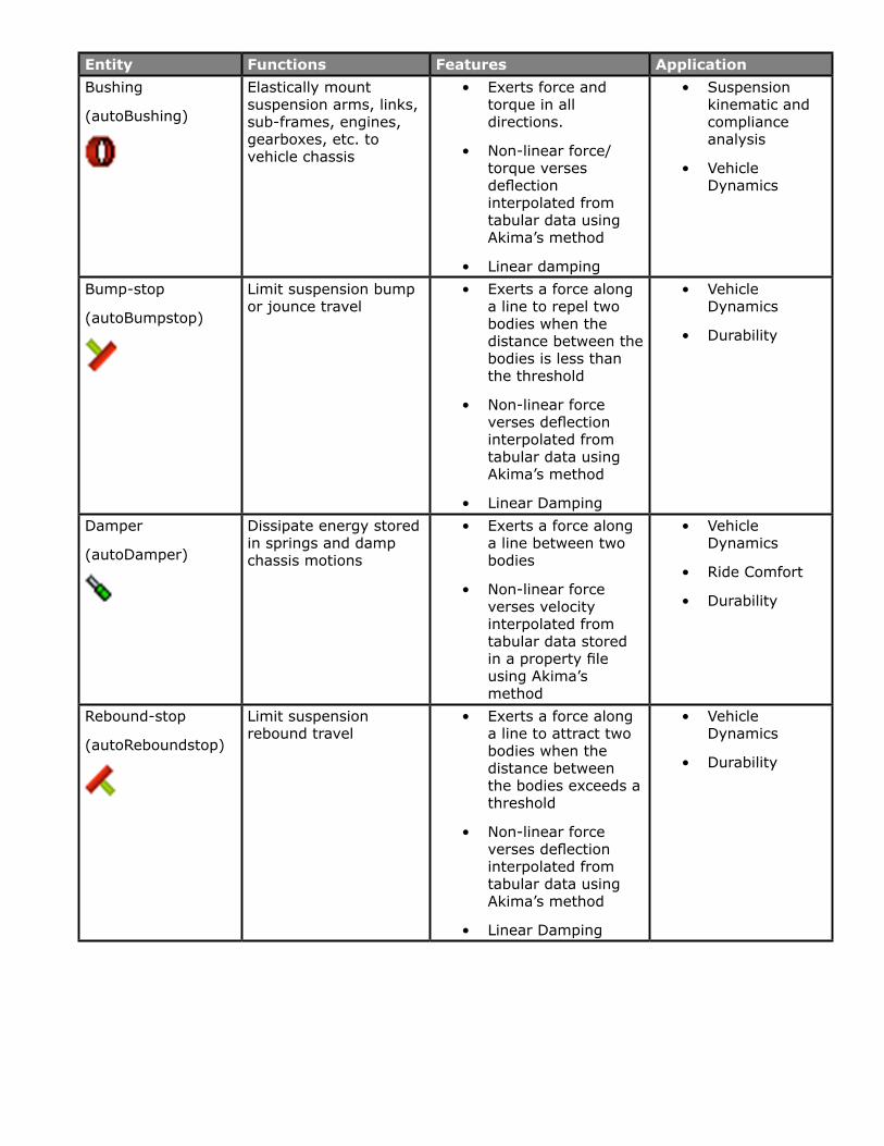
MBD – Vehicle Dynamics Tools
The MBD – Vehicle Dynamics Tools in MotionSolve and MotionView are a set of modeling entities for bushings, bump-stops, dampers, rebound-stops, springs and tires that extend the capabilities of MotionSolve.
Common to all of these are the following:
• An equal but opposite force is applied on two bodies that these entities are defined between
• The force applied depends on the displacement and velocity of one body relative to the other
• Outputs specific to each entity are supported, for example tire lateral slip angle for the tire entity
• The parameters (for example stiffness), used to compute the force are stored in a property file that is independent of the MotionView MDL file and the MotionSolve input deck. The property files are
– Text files and may be viewed and edited using any common text editor
– Compatible with Adams/CarTM – property files from Adams/CarTM may be reused with the Auto Entities in MotionView
– Read by MotionSolve just prior to analysis.
The table below gives more information about these entities.
Entity Functions Features ApplicationBushing
(autoBushing)
Elastically mount suspension arms, links, sub-frames, engines, gearboxes, etc. to vehicle chassis
• Exerts force and torque in all directions.
• Non-linear force/torque verses deflection interpolated from tabular data using Akima’s method
• Linear damping
• Suspension kinematic and compliance analysis
• Vehicle Dynamics
Bump-stop
(autoBumpstop)
Limit suspension bump or jounce travel
• Exerts a force along a line to repel two bodies when the distance between the bodies is less than the threshold
• Non-linear force verses deflection interpolated from tabular data using Akima’s method
• Linear Damping
• Vehicle Dynamics
• Durability
Damper
(autoDamper)
Dissipate energy stored in springs and damp chassis motions
• Exerts a force along a line between two bodies
• Non-linear force verses velocity interpolated from tabular data stored in a property file using Akima’s method
• Vehicle Dynamics
• Ride Comfort
• Durability
Rebound-stop
(autoReboundstop)
Limit suspension rebound travel
• Exerts a force along a line to attract two bodies when the distance between the bodies exceeds a threshold
• Non-linear force verses deflection interpolated from tabular data using Akima’s method
• Linear Damping
• Vehicle Dynamics
• Durability
Spring
(autoSpring)
Limit forces in suspension components and isolate chassis by absorbing energy from vertical road inputs
• Exerts a force along a line between two bodies.
• Non-linear force verses deflection interpolated from tabular data using Akima’s methods
• Optionally set the initial load or length of the spring at vehicle input position
• Suspension Kinematics and Compliance
• Vehicle Dynamics
• Ride Comfort
• Durability
Tire – CTI
(autoTireCTI)
Generate forces for steering, accelerating, and braking. Isolate the vehicle from small road irregularities
• COSIN FTIRE (flexible ring), FIALA, and Pacejka 2000 Magic Formula tire models
• 3D and 2D Road Models including Curved Gridded Road (CRG) and COSIN RGR.
• FTIRE: Ride Comfort & Durability
• Pacejka 2000: – Vehicle Dynamics
Tire – CD
(autoTireCD)
Generate forces for steering, accelerating, and braking. Isolate the vehicle from small road irregularities
• Supports family of CD-Tire models (flexible ring)
• 2D and 3D Road Models including CRG
• Vehicle Dynamics
• Ride Comfort
• Durability
Tire – TNO
(autoTireTNO)
Generate forces for steering, accelerating, and braking. Isolate the vehicle from small road irregularities
• MF-TYRE
• SWIFT-TYRE (rigid-ring)
• 2D and 3D Road Models, including CRG
• MF-Tyre: Vehicle Dynamics
• SWIFT-Tyre: Vehicle Dynamics & Ride Comfort
ADAMS Compatibility
Additional Support for Model Units
More options for choosing the model units are now available. Some of these include MegaNewton, Poundal, US Ton, Yard, Nanosecond, Day etc.
Modal Force Translation
This release contains a fix for translating the MFORCE element from an adm/acf deck when the SCALE attribute is defined as a function expression.
Joint Friction Model Definition
Some attributes within the FRICTION definition in an adm/acf deck were wrongly translated to the MotionSolve XML input deck. This has been resolved.
Resolved Issues
Contact Force Visualization
While visualizing contact force vectors in HyperView, the force vectors are now correctly drawn to originate from the point(s) of contact instead of the body CG.
Python User Subroutines
Previously, the user was unable to run a simulation from the MotionSolve GUI if their model contained a Python user-subroutine. This has been fixed within this release.
User Defined Graphics
With this release, an issue with MotionSolve post when using User Defined Graphics has been resolved allowing the user to visualize their custom graphics.
Deactivating Joints
Previously, if you deactivated a joint between simulations, any motions associated with that joint would still be active which could lead to erroneous results. Now, in such a situation, any motions associated with a deactivated joint are deactivated automatically and a warning message is printed out to alert the user of the same.
TIMGET Utility Function
The TIMGET function always returned “0” as the current time when it was called from a user-subroutine during a static or quasi-static simulation. This has been fixed.
Forced Assembly Analysis and Initial Velocity Calculation
Previously, the initial velocity calculations were reset if you forced an assembly analysis before a transient simulation. This led to incorrect initial velocities in the subsequent transient analysis. The correct behavior is to re-calculate initial velocities after a forced assembly analysis. This is implemented in the current release.
Documentation
A number of errors in the documentation have been resolved for both model and command elements.
HyperXtrude Solver 12.0.210 ReleaseThere have been major performance enhancements for all HyperXtrude solvers in this release.
Solvers can now handle large problems (up to 4 million nodes).
Contents
All Solvers
Performance Enhancements
Metal Extrusion
Improvements to Solver Accuracy
Changes to Bearing Optimization Module
Mandrel Offset
Grain Size Computations
Resolved Issues
Billet Forging
Grain Size Computations
Material Models
Resin Transfer Molding
Local Coordinate System Enhancements
Automatic Time Step Determination
Resolved Issues
Highlights of the
All Solvers
Performance Enhancements
HyperXtrude Solvers can now handle large models on both Windows and LINUX 64-bit platforms. In the previous release, size was limited to 450,000 nodes on Windows machines. Now the solver can handle up to 4 million nodes on both the platforms. In addition to this, there is a significant speed improvement.
Metal Extrusion
Improvements to Solver Accuracy
Accuracy of the nose cone prediction of profiles, especially those with large variation in thicknesses, is improved.
Changes to Bearing Optimization Module
Bearing optimization will determine the imbalance in material flow at the end of bearing region instead of the exit. This improves the accuracy of the bearing optimization.
Mandrel Offset
The recommended procedure is to flush the mandrel offset before creating the mesh. This is accurate and also will result in good quality mesh in the welding chamber region. In this release, if desired, user can also mesh the model with the mandrel offset and solver will account for this step in the computation and the computed solution will be equally accurate. The advantage of including mandrel offset is savings in time spent in CAD correction; however, there may be a disadvantage in creating good quality mesh in this region.
Grain Size Computations
In this release, the default sub-grain size model has been replaced by a more accurate dynamic recrystallization (DRX) grain size model. This new model takes into account of dependence of grain size on strain and temperature corrected strain rate. Additional recrystalization and grain size calculation models can be included using User Defined Functions or a TCL command.
Resolved Issues
Error in the units printed for the surface area of boundary faces in the output balance tables in now corrected.
Billet Forging
Grain Size Computations
Solver now supports computation of grain size using static, dynamic, and metadynamic recrystallization models.
Material Models
Flow stress of the workpiece can now be computed using the following constitutive models.
• Johnson-Cook
• Norton-Hoff
• Hensel-Spittel
• Flow stress data in 3D table format (as function of strain rate, strain, temperature)
In addition, users have the choice of using the existing Sellars-Tegart and metal forming power law models.
HyperXtrude for Resin Transfer Molding
Local Coordinate System Enhancements
Solver now supports local coordinate system (cylindrical coordinates) for permeability and thermal conductivity tensors. In addition, exported H3D results now include the permeability and conductivity tensors to help visualize the local coordinate system data used in the model. The axis of the local cylindrical coordinate system can be X, Y or Z axis.
Automatic Time Step Determination
Simulation can start with a small value for time step and the solver will automatically adjusts this as filling progresses.